JP7210960B2 - Vacuum processing apparatus and substrate transfer method - Google Patents
Vacuum processing apparatus and substrate transfer methodDownload PDFInfo
- Publication number
- JP7210960B2 JP7210960B2JP2018177838AJP2018177838AJP7210960B2JP 7210960 B2JP7210960 B2JP 7210960B2JP 2018177838 AJP2018177838 AJP 2018177838AJP 2018177838 AJP2018177838 AJP 2018177838AJP 7210960 B2JP7210960 B2JP 7210960B2
- Authority
- JP
- Japan
- Prior art keywords
- substrate
- normal
- vacuum
- transfer
- normal pressure
- Prior art date
- Legal status (The legal status is an assumption and is not a legal conclusion. Google has not performed a legal analysis and makes no representation as to the accuracy of the status listed.)
- Active
Links
- 238000012545processingMethods0.000titleclaimsdescription87
- 239000000758substrateSubstances0.000titleclaimsdescription82
- 238000000034methodMethods0.000titleclaimsdescription10
- 230000007246mechanismEffects0.000claimsdescription133
- 230000007723transport mechanismEffects0.000claimsdescription26
- 238000012805post-processingMethods0.000claimsdescription14
- 230000002093peripheral effectEffects0.000claimsdescription9
- 238000007781pre-processingMethods0.000claimsdescription7
- 239000011159matrix materialSubstances0.000claimsdescription4
- 238000002203pretreatmentMethods0.000claims1
- 235000012431wafersNutrition0.000description252
- 238000001816coolingMethods0.000description32
- 239000007789gasSubstances0.000description32
- 230000000875corresponding effectEffects0.000description7
- 239000000969carrierSubstances0.000description6
- 238000010586diagramMethods0.000description6
- 230000003028elevating effectEffects0.000description5
- IJGRMHOSHXDMSA-UHFFFAOYSA-NAtomic nitrogenChemical compoundN#NIJGRMHOSHXDMSA-UHFFFAOYSA-N0.000description4
- 239000010936titaniumSubstances0.000description4
- 229910001873dinitrogenInorganic materials0.000description3
- QGZKDVFQNNGYKY-UHFFFAOYSA-NAmmoniaChemical compoundNQGZKDVFQNNGYKY-UHFFFAOYSA-N0.000description2
- XKRFYHLGVUSROY-UHFFFAOYSA-NArgonChemical compound[Ar]XKRFYHLGVUSROY-UHFFFAOYSA-N0.000description2
- 238000000231atomic layer depositionMethods0.000description2
- 230000015572biosynthetic processEffects0.000description2
- 238000006243chemical reactionMethods0.000description2
- 239000002826coolantSubstances0.000description2
- 238000004519manufacturing processMethods0.000description2
- 230000003287optical effectEffects0.000description2
- 239000002245particleSubstances0.000description2
- 239000012495reaction gasSubstances0.000description2
- 239000004065semiconductorSubstances0.000description2
- 238000003860storageMethods0.000description2
- RTAQQCXQSZGOHL-UHFFFAOYSA-NTitaniumChemical compound[Ti]RTAQQCXQSZGOHL-UHFFFAOYSA-N0.000description1
- 229910021529ammoniaInorganic materials0.000description1
- 238000000137annealingMethods0.000description1
- 229910052786argonInorganic materials0.000description1
- 230000008602contractionEffects0.000description1
- 230000001276controlling effectEffects0.000description1
- 239000000498cooling waterSubstances0.000description1
- 230000002079cooperative effectEffects0.000description1
- 230000008878couplingEffects0.000description1
- 238000010168coupling processMethods0.000description1
- 238000005859coupling reactionMethods0.000description1
- 238000001514detection methodMethods0.000description1
- 238000005530etchingMethods0.000description1
- 239000001257hydrogenSubstances0.000description1
- 229910052739hydrogenInorganic materials0.000description1
- 125000004435hydrogen atomChemical class[H]*0.000description1
- 238000009434installationMethods0.000description1
- NJPPVKZQTLUDBO-UHFFFAOYSA-NnovaluronChemical compoundC1=C(Cl)C(OC(F)(F)C(OC(F)(F)F)F)=CC=C1NC(=O)NC(=O)C1=C(F)C=CC=C1FNJPPVKZQTLUDBO-UHFFFAOYSA-N0.000description1
- 238000003825pressingMethods0.000description1
- 238000007789sealingMethods0.000description1
- 238000001179sorption measurementMethods0.000description1
- 229910052719titaniumInorganic materials0.000description1
- XJDNKRIXUMDJCW-UHFFFAOYSA-Jtitanium tetrachlorideChemical compoundCl[Ti](Cl)(Cl)ClXJDNKRIXUMDJCW-UHFFFAOYSA-J0.000description1
Images


Classifications
- H—ELECTRICITY
- H01—ELECTRIC ELEMENTS
- H01L—SEMICONDUCTOR DEVICES NOT COVERED BY CLASS H10
- H01L21/00—Processes or apparatus adapted for the manufacture or treatment of semiconductor or solid state devices or of parts thereof
- H01L21/67—Apparatus specially adapted for handling semiconductor or electric solid state devices during manufacture or treatment thereof; Apparatus specially adapted for handling wafers during manufacture or treatment of semiconductor or electric solid state devices or components ; Apparatus not specifically provided for elsewhere
- H01L21/67005—Apparatus not specifically provided for elsewhere
- H01L21/67011—Apparatus for manufacture or treatment
- H01L21/67155—Apparatus for manufacturing or treating in a plurality of work-stations
- H01L21/67196—Apparatus for manufacturing or treating in a plurality of work-stations characterized by the construction of the transfer chamber
- C—CHEMISTRY; METALLURGY
- C23—COATING METALLIC MATERIAL; COATING MATERIAL WITH METALLIC MATERIAL; CHEMICAL SURFACE TREATMENT; DIFFUSION TREATMENT OF METALLIC MATERIAL; COATING BY VACUUM EVAPORATION, BY SPUTTERING, BY ION IMPLANTATION OR BY CHEMICAL VAPOUR DEPOSITION, IN GENERAL; INHIBITING CORROSION OF METALLIC MATERIAL OR INCRUSTATION IN GENERAL
- C23C—COATING METALLIC MATERIAL; COATING MATERIAL WITH METALLIC MATERIAL; SURFACE TREATMENT OF METALLIC MATERIAL BY DIFFUSION INTO THE SURFACE, BY CHEMICAL CONVERSION OR SUBSTITUTION; COATING BY VACUUM EVAPORATION, BY SPUTTERING, BY ION IMPLANTATION OR BY CHEMICAL VAPOUR DEPOSITION, IN GENERAL
- C23C14/00—Coating by vacuum evaporation, by sputtering or by ion implantation of the coating forming material
- C23C14/22—Coating by vacuum evaporation, by sputtering or by ion implantation of the coating forming material characterised by the process of coating
- C23C14/56—Apparatus specially adapted for continuous coating; Arrangements for maintaining the vacuum, e.g. vacuum locks
- C—CHEMISTRY; METALLURGY
- C23—COATING METALLIC MATERIAL; COATING MATERIAL WITH METALLIC MATERIAL; CHEMICAL SURFACE TREATMENT; DIFFUSION TREATMENT OF METALLIC MATERIAL; COATING BY VACUUM EVAPORATION, BY SPUTTERING, BY ION IMPLANTATION OR BY CHEMICAL VAPOUR DEPOSITION, IN GENERAL; INHIBITING CORROSION OF METALLIC MATERIAL OR INCRUSTATION IN GENERAL
- C23C—COATING METALLIC MATERIAL; COATING MATERIAL WITH METALLIC MATERIAL; SURFACE TREATMENT OF METALLIC MATERIAL BY DIFFUSION INTO THE SURFACE, BY CHEMICAL CONVERSION OR SUBSTITUTION; COATING BY VACUUM EVAPORATION, BY SPUTTERING, BY ION IMPLANTATION OR BY CHEMICAL VAPOUR DEPOSITION, IN GENERAL
- C23C16/00—Chemical coating by decomposition of gaseous compounds, without leaving reaction products of surface material in the coating, i.e. chemical vapour deposition [CVD] processes
- C23C16/44—Chemical coating by decomposition of gaseous compounds, without leaving reaction products of surface material in the coating, i.e. chemical vapour deposition [CVD] processes characterised by the method of coating
- C23C16/4401—Means for minimising impurities, e.g. dust, moisture or residual gas, in the reaction chamber
- C—CHEMISTRY; METALLURGY
- C23—COATING METALLIC MATERIAL; COATING MATERIAL WITH METALLIC MATERIAL; CHEMICAL SURFACE TREATMENT; DIFFUSION TREATMENT OF METALLIC MATERIAL; COATING BY VACUUM EVAPORATION, BY SPUTTERING, BY ION IMPLANTATION OR BY CHEMICAL VAPOUR DEPOSITION, IN GENERAL; INHIBITING CORROSION OF METALLIC MATERIAL OR INCRUSTATION IN GENERAL
- C23C—COATING METALLIC MATERIAL; COATING MATERIAL WITH METALLIC MATERIAL; SURFACE TREATMENT OF METALLIC MATERIAL BY DIFFUSION INTO THE SURFACE, BY CHEMICAL CONVERSION OR SUBSTITUTION; COATING BY VACUUM EVAPORATION, BY SPUTTERING, BY ION IMPLANTATION OR BY CHEMICAL VAPOUR DEPOSITION, IN GENERAL
- C23C16/00—Chemical coating by decomposition of gaseous compounds, without leaving reaction products of surface material in the coating, i.e. chemical vapour deposition [CVD] processes
- C23C16/44—Chemical coating by decomposition of gaseous compounds, without leaving reaction products of surface material in the coating, i.e. chemical vapour deposition [CVD] processes characterised by the method of coating
- C23C16/54—Apparatus specially adapted for continuous coating
- H—ELECTRICITY
- H01—ELECTRIC ELEMENTS
- H01L—SEMICONDUCTOR DEVICES NOT COVERED BY CLASS H10
- H01L21/00—Processes or apparatus adapted for the manufacture or treatment of semiconductor or solid state devices or of parts thereof
- H01L21/02—Manufacture or treatment of semiconductor devices or of parts thereof
- H01L21/04—Manufacture or treatment of semiconductor devices or of parts thereof the devices having potential barriers, e.g. a PN junction, depletion layer or carrier concentration layer
- H01L21/18—Manufacture or treatment of semiconductor devices or of parts thereof the devices having potential barriers, e.g. a PN junction, depletion layer or carrier concentration layer the devices having semiconductor bodies comprising elements of Group IV of the Periodic Table or AIIIBV compounds with or without impurities, e.g. doping materials
- H01L21/30—Treatment of semiconductor bodies using processes or apparatus not provided for in groups H01L21/20 - H01L21/26
- H01L21/302—Treatment of semiconductor bodies using processes or apparatus not provided for in groups H01L21/20 - H01L21/26 to change their surface-physical characteristics or shape, e.g. etching, polishing, cutting
- H01L21/306—Chemical or electrical treatment, e.g. electrolytic etching
- H01L21/3065—Plasma etching; Reactive-ion etching
- H—ELECTRICITY
- H01—ELECTRIC ELEMENTS
- H01L—SEMICONDUCTOR DEVICES NOT COVERED BY CLASS H10
- H01L21/00—Processes or apparatus adapted for the manufacture or treatment of semiconductor or solid state devices or of parts thereof
- H01L21/67—Apparatus specially adapted for handling semiconductor or electric solid state devices during manufacture or treatment thereof; Apparatus specially adapted for handling wafers during manufacture or treatment of semiconductor or electric solid state devices or components ; Apparatus not specifically provided for elsewhere
- H01L21/67005—Apparatus not specifically provided for elsewhere
- H01L21/67011—Apparatus for manufacture or treatment
- H01L21/67155—Apparatus for manufacturing or treating in a plurality of work-stations
- H01L21/67161—Apparatus for manufacturing or treating in a plurality of work-stations characterized by the layout of the process chambers
- H01L21/67173—Apparatus for manufacturing or treating in a plurality of work-stations characterized by the layout of the process chambers in-line arrangement
- H—ELECTRICITY
- H01—ELECTRIC ELEMENTS
- H01L—SEMICONDUCTOR DEVICES NOT COVERED BY CLASS H10
- H01L21/00—Processes or apparatus adapted for the manufacture or treatment of semiconductor or solid state devices or of parts thereof
- H01L21/67—Apparatus specially adapted for handling semiconductor or electric solid state devices during manufacture or treatment thereof; Apparatus specially adapted for handling wafers during manufacture or treatment of semiconductor or electric solid state devices or components ; Apparatus not specifically provided for elsewhere
- H01L21/67005—Apparatus not specifically provided for elsewhere
- H01L21/67011—Apparatus for manufacture or treatment
- H01L21/67155—Apparatus for manufacturing or treating in a plurality of work-stations
- H01L21/67201—Apparatus for manufacturing or treating in a plurality of work-stations characterized by the construction of the load-lock chamber
- H—ELECTRICITY
- H01—ELECTRIC ELEMENTS
- H01L—SEMICONDUCTOR DEVICES NOT COVERED BY CLASS H10
- H01L21/00—Processes or apparatus adapted for the manufacture or treatment of semiconductor or solid state devices or of parts thereof
- H01L21/67—Apparatus specially adapted for handling semiconductor or electric solid state devices during manufacture or treatment thereof; Apparatus specially adapted for handling wafers during manufacture or treatment of semiconductor or electric solid state devices or components ; Apparatus not specifically provided for elsewhere
- H01L21/677—Apparatus specially adapted for handling semiconductor or electric solid state devices during manufacture or treatment thereof; Apparatus specially adapted for handling wafers during manufacture or treatment of semiconductor or electric solid state devices or components ; Apparatus not specifically provided for elsewhere for conveying, e.g. between different workstations
- H01L21/67739—Apparatus specially adapted for handling semiconductor or electric solid state devices during manufacture or treatment thereof; Apparatus specially adapted for handling wafers during manufacture or treatment of semiconductor or electric solid state devices or components ; Apparatus not specifically provided for elsewhere for conveying, e.g. between different workstations into and out of processing chamber
- H01L21/67742—Mechanical parts of transfer devices
- H—ELECTRICITY
- H01—ELECTRIC ELEMENTS
- H01L—SEMICONDUCTOR DEVICES NOT COVERED BY CLASS H10
- H01L21/00—Processes or apparatus adapted for the manufacture or treatment of semiconductor or solid state devices or of parts thereof
- H01L21/67—Apparatus specially adapted for handling semiconductor or electric solid state devices during manufacture or treatment thereof; Apparatus specially adapted for handling wafers during manufacture or treatment of semiconductor or electric solid state devices or components ; Apparatus not specifically provided for elsewhere
- H01L21/677—Apparatus specially adapted for handling semiconductor or electric solid state devices during manufacture or treatment thereof; Apparatus specially adapted for handling wafers during manufacture or treatment of semiconductor or electric solid state devices or components ; Apparatus not specifically provided for elsewhere for conveying, e.g. between different workstations
- H01L21/67739—Apparatus specially adapted for handling semiconductor or electric solid state devices during manufacture or treatment thereof; Apparatus specially adapted for handling wafers during manufacture or treatment of semiconductor or electric solid state devices or components ; Apparatus not specifically provided for elsewhere for conveying, e.g. between different workstations into and out of processing chamber
- H01L21/67754—Apparatus specially adapted for handling semiconductor or electric solid state devices during manufacture or treatment thereof; Apparatus specially adapted for handling wafers during manufacture or treatment of semiconductor or electric solid state devices or components ; Apparatus not specifically provided for elsewhere for conveying, e.g. between different workstations into and out of processing chamber horizontal transfer of a batch of workpieces
- H—ELECTRICITY
- H01—ELECTRIC ELEMENTS
- H01L—SEMICONDUCTOR DEVICES NOT COVERED BY CLASS H10
- H01L21/00—Processes or apparatus adapted for the manufacture or treatment of semiconductor or solid state devices or of parts thereof
- H01L21/67—Apparatus specially adapted for handling semiconductor or electric solid state devices during manufacture or treatment thereof; Apparatus specially adapted for handling wafers during manufacture or treatment of semiconductor or electric solid state devices or components ; Apparatus not specifically provided for elsewhere
- H01L21/677—Apparatus specially adapted for handling semiconductor or electric solid state devices during manufacture or treatment thereof; Apparatus specially adapted for handling wafers during manufacture or treatment of semiconductor or electric solid state devices or components ; Apparatus not specifically provided for elsewhere for conveying, e.g. between different workstations
- H01L21/67763—Apparatus specially adapted for handling semiconductor or electric solid state devices during manufacture or treatment thereof; Apparatus specially adapted for handling wafers during manufacture or treatment of semiconductor or electric solid state devices or components ; Apparatus not specifically provided for elsewhere for conveying, e.g. between different workstations the wafers being stored in a carrier, involving loading and unloading
- H01L21/67766—Mechanical parts of transfer devices
- H—ELECTRICITY
- H01—ELECTRIC ELEMENTS
- H01L—SEMICONDUCTOR DEVICES NOT COVERED BY CLASS H10
- H01L21/00—Processes or apparatus adapted for the manufacture or treatment of semiconductor or solid state devices or of parts thereof
- H01L21/67—Apparatus specially adapted for handling semiconductor or electric solid state devices during manufacture or treatment thereof; Apparatus specially adapted for handling wafers during manufacture or treatment of semiconductor or electric solid state devices or components ; Apparatus not specifically provided for elsewhere
- H01L21/677—Apparatus specially adapted for handling semiconductor or electric solid state devices during manufacture or treatment thereof; Apparatus specially adapted for handling wafers during manufacture or treatment of semiconductor or electric solid state devices or components ; Apparatus not specifically provided for elsewhere for conveying, e.g. between different workstations
- H01L21/67763—Apparatus specially adapted for handling semiconductor or electric solid state devices during manufacture or treatment thereof; Apparatus specially adapted for handling wafers during manufacture or treatment of semiconductor or electric solid state devices or components ; Apparatus not specifically provided for elsewhere for conveying, e.g. between different workstations the wafers being stored in a carrier, involving loading and unloading
- H01L21/67775—Docking arrangements
- H—ELECTRICITY
- H01—ELECTRIC ELEMENTS
- H01L—SEMICONDUCTOR DEVICES NOT COVERED BY CLASS H10
- H01L21/00—Processes or apparatus adapted for the manufacture or treatment of semiconductor or solid state devices or of parts thereof
- H01L21/67—Apparatus specially adapted for handling semiconductor or electric solid state devices during manufacture or treatment thereof; Apparatus specially adapted for handling wafers during manufacture or treatment of semiconductor or electric solid state devices or components ; Apparatus not specifically provided for elsewhere
- H01L21/68—Apparatus specially adapted for handling semiconductor or electric solid state devices during manufacture or treatment thereof; Apparatus specially adapted for handling wafers during manufacture or treatment of semiconductor or electric solid state devices or components ; Apparatus not specifically provided for elsewhere for positioning, orientation or alignment
- H01L21/681—Apparatus specially adapted for handling semiconductor or electric solid state devices during manufacture or treatment thereof; Apparatus specially adapted for handling wafers during manufacture or treatment of semiconductor or electric solid state devices or components ; Apparatus not specifically provided for elsewhere for positioning, orientation or alignment using optical controlling means
- H—ELECTRICITY
- H01—ELECTRIC ELEMENTS
- H01L—SEMICONDUCTOR DEVICES NOT COVERED BY CLASS H10
- H01L21/00—Processes or apparatus adapted for the manufacture or treatment of semiconductor or solid state devices or of parts thereof
- H01L21/67—Apparatus specially adapted for handling semiconductor or electric solid state devices during manufacture or treatment thereof; Apparatus specially adapted for handling wafers during manufacture or treatment of semiconductor or electric solid state devices or components ; Apparatus not specifically provided for elsewhere
- H01L21/683—Apparatus specially adapted for handling semiconductor or electric solid state devices during manufacture or treatment thereof; Apparatus specially adapted for handling wafers during manufacture or treatment of semiconductor or electric solid state devices or components ; Apparatus not specifically provided for elsewhere for supporting or gripping
- H01L21/687—Apparatus specially adapted for handling semiconductor or electric solid state devices during manufacture or treatment thereof; Apparatus specially adapted for handling wafers during manufacture or treatment of semiconductor or electric solid state devices or components ; Apparatus not specifically provided for elsewhere for supporting or gripping using mechanical means, e.g. chucks, clamps or pinches
- H01L21/68707—Apparatus specially adapted for handling semiconductor or electric solid state devices during manufacture or treatment thereof; Apparatus specially adapted for handling wafers during manufacture or treatment of semiconductor or electric solid state devices or components ; Apparatus not specifically provided for elsewhere for supporting or gripping using mechanical means, e.g. chucks, clamps or pinches the wafers being placed on a robot blade, or gripped by a gripper for conveyance
- H—ELECTRICITY
- H01—ELECTRIC ELEMENTS
- H01L—SEMICONDUCTOR DEVICES NOT COVERED BY CLASS H10
- H01L21/00—Processes or apparatus adapted for the manufacture or treatment of semiconductor or solid state devices or of parts thereof
- H01L21/67—Apparatus specially adapted for handling semiconductor or electric solid state devices during manufacture or treatment thereof; Apparatus specially adapted for handling wafers during manufacture or treatment of semiconductor or electric solid state devices or components ; Apparatus not specifically provided for elsewhere
- H01L21/683—Apparatus specially adapted for handling semiconductor or electric solid state devices during manufacture or treatment thereof; Apparatus specially adapted for handling wafers during manufacture or treatment of semiconductor or electric solid state devices or components ; Apparatus not specifically provided for elsewhere for supporting or gripping
- H01L21/687—Apparatus specially adapted for handling semiconductor or electric solid state devices during manufacture or treatment thereof; Apparatus specially adapted for handling wafers during manufacture or treatment of semiconductor or electric solid state devices or components ; Apparatus not specifically provided for elsewhere for supporting or gripping using mechanical means, e.g. chucks, clamps or pinches
- H01L21/68714—Apparatus specially adapted for handling semiconductor or electric solid state devices during manufacture or treatment thereof; Apparatus specially adapted for handling wafers during manufacture or treatment of semiconductor or electric solid state devices or components ; Apparatus not specifically provided for elsewhere for supporting or gripping using mechanical means, e.g. chucks, clamps or pinches the wafers being placed on a susceptor, stage or support
- H01L21/6875—Apparatus specially adapted for handling semiconductor or electric solid state devices during manufacture or treatment thereof; Apparatus specially adapted for handling wafers during manufacture or treatment of semiconductor or electric solid state devices or components ; Apparatus not specifically provided for elsewhere for supporting or gripping using mechanical means, e.g. chucks, clamps or pinches the wafers being placed on a susceptor, stage or support characterised by a plurality of individual support members, e.g. support posts or protrusions
Landscapes
- Engineering & Computer Science (AREA)
- Physics & Mathematics (AREA)
- Condensed Matter Physics & Semiconductors (AREA)
- General Physics & Mathematics (AREA)
- Manufacturing & Machinery (AREA)
- Computer Hardware Design (AREA)
- Microelectronics & Electronic Packaging (AREA)
- Power Engineering (AREA)
- Chemical & Material Sciences (AREA)
- Robotics (AREA)
- Chemical Kinetics & Catalysis (AREA)
- Materials Engineering (AREA)
- Mechanical Engineering (AREA)
- Metallurgy (AREA)
- Organic Chemistry (AREA)
- General Chemical & Material Sciences (AREA)
- Plasma & Fusion (AREA)
- Container, Conveyance, Adherence, Positioning, Of Wafer (AREA)
- Physical Vapour Deposition (AREA)
- Chemical Vapour Deposition (AREA)
- Drying Of Semiconductors (AREA)
Description
Translated fromJapanese本開示は、真空処理装置及び基板を搬送する技術に関する。 TECHNICAL FIELD The present disclosure relates to a technique for transporting a vacuum processing apparatus and a substrate.
半導体デバイスの製造工程における真空処理を行う真空処理装置は、常圧雰囲気と真空雰囲気とを切り替えるロードロックモジュールを備え、搬送容器に収納されて搬送された半導体ウエハ(以下「ウエハ」という。)を常圧搬送室を介してロードロックモジュールに搬送する。そしてロードロックモジュール内を常圧雰囲気から真空雰囲気に切り替えた後、真空搬送室を介して例えば複数の真空処理部に夫々ウエハを搬送する。
例えば特許文献1には、水平に並べた2枚のウエハWを処理する処理モジュールを備えた真空処理装置において、常圧雰囲気と真空雰囲気とを切り替えるロードロックモジュールに基板を左右に2枚並べて配置した構成が記載されている。この真空処理装置では、搬送アームによりロードロックモジュール及び処理モジュールの間で2枚のウエハを一括して受け渡しができるように構成している。A vacuum processing apparatus that performs vacuum processing in a semiconductor device manufacturing process includes a load lock module that switches between a normal pressure atmosphere and a vacuum atmosphere, and stores semiconductor wafers (hereinafter referred to as "wafers") transported in a transport container. Transfer to the load lock module via the normal pressure transfer chamber. After the normal pressure atmosphere in the load lock module is switched to the vacuum atmosphere, the wafers are transferred to, for example, a plurality of vacuum processing units through the vacuum transfer chamber.
For example, in
本開示はこのような事情の下になされたものであり、真空雰囲気下で基板に処理を行う真空処理装置において、装置のフットプリントの増加を防ぐ技術を提供することにある。 The present disclosure has been made under such circumstances, and it is an object of the present disclosure to provide a technique for preventing an increase in the footprint of a vacuum processing apparatus that processes substrates in a vacuum atmosphere.
本開示の真空処理装置は、内部が常圧雰囲気と真空雰囲気とで切り替え自在で、左右の各々に形成された開閉自在な第1の基板搬送口と後方に形成された開閉自在な第2の基板搬送口とを備えた筐体と、前記筐体内にて基板を左右に各々保持する複数の基板保持部と、を備えたロードロックモジュールと、
前記筐体の後方に接続され、前記第2の基板搬送口が開口する真空雰囲気の真空搬送室と、
前記真空搬送室に接続され、前記基板を真空処理するための処理モジュールと、
前記ロードロックモジュールと前記搬送室と前記処理モジュールとの間で前記基板を搬送する真空搬送機構と、
前記各第1の基板搬送口が開口するように前記筐体の上方または下方を跨いで当該筐体の左右の一方から他方へ亘って形成され、当該筐体に重なる前記基板の搬送領域である積層搬送領域を備える常圧雰囲気の常圧搬送室と、
前記常圧搬送室の外側の左右に各々設けられた、前記基板を格納する搬送容器を搬入出する複数の搬入出ポートと、
前記積層搬送領域を経由して前記各搬入出ポートに搬入された前記搬送容器と前記各基板保持部との間で前記基板を搬送する常圧搬送機構と、
を備えている。The vacuum processing apparatus of the present disclosure is capable of switching between a normal pressure atmosphere and a vacuum atmosphere inside, and has a freely openable and closable first substrate transport port formed on each of the left and right sides and a freely openable and closable second substrate transport port formed at the rear. a load lock module comprising: a housing having a board transfer port; and a plurality of board holding parts for holding left and right boards in the housing;
a vacuum transfer chamber connected to the rear of the housing and having a vacuum atmosphere in which the second substrate transfer port is open;
a processing module connected to the vacuum transfer chamber for vacuum processing the substrate;
a vacuum transfer mechanism that transfers the substrate between the load lock module, the transfer chamber, and the processing module;
A transfer area for the substrate that is formed from one to the other of the left and right sides of the housing so as to straddle the upper side or the lower side of the housing so that each of the first substrate transfer ports is open, and that overlaps with the housing. a normal-pressure transfer chamber with a normal-pressure atmosphere having a stacking transfer area;
a plurality of loading/unloading ports for loading/unloading the transfer containers for storing the substrates, respectively provided on the left and right sides of the normal pressure transfer chamber;
a normal-pressure transport mechanism for transporting the substrate between the transport container loaded into each of the loading/unloading ports via the stacking transport area and each of the substrate holding units;
It has
本開示によれば、真空雰囲気下で基板に処理を行う真空処理装置において、装置のフットプリントの増加を防ぐことができる。 According to the present disclosure, it is possible to prevent an increase in the footprint of a vacuum processing apparatus that processes a substrate in a vacuum atmosphere.
[第1の実施の形態]
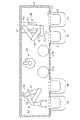
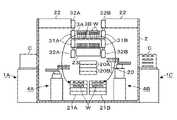
一実施の形態に係る真空処理装置について説明する。図1~図3に示すように、この真空処理装置は、その内部雰囲気がクリーンエア、一例として乾燥ガスにより常圧雰囲気(空気の場合には大気雰囲気ということもできる)とされる左右方向に伸びる矩形の常圧搬送室2を備えている。[First embodiment]
A vacuum processing apparatus according to one embodiment will be described. As shown in FIGS. 1 to 3, this vacuum processing apparatus has an internal atmosphere of clean air, for example dry gas, which is a normal pressure atmosphere (in the case of air, it can be called an atmospheric atmosphere). It has an elongated rectangular normal
また真空処理装置は、上下に積層された2台のロードロックモジュール3A、3Bを備え、常圧搬送室2は、ロードロックモジュール3A、3Bの下方を跨いで当該ロードロックモジュール3A、3Bの左右の一方から他方へ亘って形成されている。
また常圧搬送室2内におけるロードロックモジュール3A、3Bの下方の領域は、基板であるウエハWを搬送する搬送領域となっている。当該ロードロックモジュール3A、3Bと積層される搬送領域は、積層搬送領域に相当する。ロードロックモジュール3A、3Bの下方の領域には、載置部に相当する冷却モジュール21A、21Bと、アライメントモジュール20と、が設けられている。
常圧搬送室2の前方側には、ウエハWの搬送容器であるキャリアCを載置するため4台の搬入出ポート1A~1Dが設けられている。以後搬入出ポート1A~1D側を前方、常圧搬送室2側を後方として説明する。搬入出ポート1A~1Dは、前方から見たときにロードロックモジュール3A、3Bの左右に外れた位置に、左右に各々2台ずつ配置されており、左側から右側に向けて1A、1B、1C、1Dの順に搬送されているものとする。また搬入出ポート1A~1Dは、図3に示すように搬入出ポート1A~1Dに載置されたキャリアCがロードロックモジュール3A、3Bと、冷却モジュール21A、21B及びアライメントモジュール20と、の間の高さ位置になるように設置されている。なお図1、2中の符号11は、キャリアCの蓋部と共に開放されるドアである。The vacuum processing apparatus also includes two vertically stacked load-
A region below the
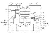
Four loading/
また図3に示すように常圧搬送室2における冷却モジュール21A、21B、アライメントモジュール20及びロードロックモジュール3A、3Bを挟む左右の領域の底部には、夫々第1の常圧搬送機構4A、第2の常圧搬送機構4Bが設けられている。前方から見て、左側に第1の常圧搬送機構4Aが、右側に第2の常圧搬送機構4Bが夫々配置されている。第1の常圧搬送機構4Aは、搬入出ポート1A~1Dのうち、搬入出ポート1A、1Bに搬送されたキャリアCのウエハWの受け渡しに専用される。第2の常圧搬送機構4Bは、搬入出ポート1A~1Dのうち、搬入出ポート1C、1Dに搬送されたキャリアCのウエハWの受け渡しに専用される。 As shown in FIG. 3, at the bottom of left and right regions sandwiching the
第1の常圧搬送機構4A及び第2の常圧搬送機構4Bは略同じ構成であることから、第1の常圧搬送機構4Aを例に説明する。第1の常圧搬送機構4Aは、不図示の回転軸を介して接続された下段アーム部41、上段アーム部42を連結した関節アームとして構成されている。さらに各々ウエハWを保持するフォーク状の2本の支持フォーク部43が上段アーム部42の先端に回転軸を介して接続されている。2本の支持フォーク部43は、互いに独立して回動するように構成され、各々先端側に1枚のウエハWを保持することができる。 Since the first normal-
図3に示すように第1の常圧搬送機構4Aは、常圧搬送室2の底面に固定された基台40を備えている。基台40は、下段部材40Aと、下段部材40Aの上面から突没するように設けられた中段部材と40Bと、中段部材40Bの上面から突没するように設けられた上段部材40Cとを備え、上段部材40Cの上面に下段アーム部41の基端側が回動自在に接続されている。そして中段部材40B及び上段部材40Cが夫々下段部材40A及び中段部材40Bから突没することにより基台40の高さが変わり、支持フォーク部43の高さ位置を変更することができる。なお基台40の伸縮により支持フォーク部43の高さ位置は、後述するアライメントモジュール20及び冷却モジュール21A、21BにウエハWを受け渡すことができる高さ位置よりも低い高さ位置から、上側のロードロックモジュール3AにウエハWを受け渡すことができる高さ位置まで可変となっている。 As shown in FIG. 3, the first normal-
続いてロードロックモジュール3A、3Bについて説明する。ロードロックモジュール3A、3Bは、ほぼ同様に構成されることから、上側のロードロックモジュール3Aを例に説明する。ロードロックモジュール3Aは、内部が常圧雰囲気と真空雰囲気とで切り替え自在な筐体30を備えている。図1、図4に示すように筐体30は、扁平な矩形状に形成され、筐体30の前方壁、後方壁は、常圧搬送室2の前方壁、後方壁に夫々概ね揃うように形成されている。 Next,
筐体30内には、左右2列、前後2行に並び各々2枚のウエハWを保持するように構成された4つの棚部38が設けられている。各棚部38は、図5に示すように筐体30の底面から上方に突出する3本の支持ピン35によりウエハWの周縁を下方から支持する下段側のウエハ保持部38Bを備えている。また棚部38は、筐体30の底面に設けられた台座部36の上面から水平に伸びる3本の支持梁37によって下段側のウエハ保持部38Bに保持されたウエハWの上方にて、ウエハWの周縁の下部を支持する上段側のウエハ保持部38Aを備えている。各支持梁37は、その先端でウエハWの周縁を支持し、支持梁37の先端部が支持ピン35の上方に揃うように配置されている。 In the
筐体30の左側面には、前方から見て左側の棚部38に保持されるウエハWに対応する位置に、夫々第1の常圧搬送機構4Aが進入する左側搬送路31Aが形成されている。また筐体30の右側面には、前方から見て右側の棚部38に保持されるウエハWに対応する位置に、第2の常圧搬送機構4Bが進入する右側搬送路31Bが形成されている。左側搬送路31A及び右側搬送路31Bには夫々ゲートバルブ32A及び32Bが設けられている。従って、ゲートバルブ32A、32Bにより、左側搬送路31A、右側搬送路31Bの開閉が夫々行われる。左側搬送路31A及び右側搬送路31Bは、第1の基板搬送口に相当する。また筐体30の後方側の側面には、後述する真空搬送室9と連結し、真空搬送室9に設けられた真空搬送機構51が進入する後方側搬送路33が形成されている。後方側搬送路33には、ゲートバルブ34が設けられている。後方側搬送路33は、第2の基板搬送口に相当する。従って、ゲートバルブ34により、後方側搬送路33の開閉が行われる。 On the left side surface of the
以下、特に記載無い場合、左側、右側については前方から見たときの左側、右側であるものとする。上記のウエハ保持部38A、38Bのうち、左側のウエハ保持部38A、38Bについては第1の常圧搬送機構4Aにより、右側のウエハ保持部38A、38Bについては第2の常圧搬送機構4Bにより夫々ウエハWの受け渡しが行われる。第1の常圧搬送機構4A及び第2の常圧搬送機構4Bの支持フォーク部43をウエハ保持部38A、ウエハ保持部38Bに対して昇降させることで、支持フォーク部43と、ウエハ保持部38A及びウエハ保持部38Bと、の間で各々ウエハWが受け渡される。そのように筐体30内にてウエハ保持部38A、38Bに各々ウエハWを受け渡すために支持フォーク部43が昇降する位置をウエハWの受け渡し位置とする。図4に示すように3本の支持梁37は、支持フォーク部43をウエハWの受け渡し位置に進入させて、昇降させたときに支持梁37と、支持フォーク部43と、が互いに干渉しないように設けられている。また支持ピン35は、夫々支持梁37の先端部の下方に揃うように配置されていることから、ウエハWの受け渡し位置にて支持フォーク部43を昇降させたときに支持ピン35と、支持フォーク部43と、が互いに干渉しない。なお、真空搬送室9から搬送されるウエハWは、成膜処理が行われておりパーティクル発生源となるおそれがあることから、上段側のウエハ保持部38Aが常圧搬送室2から搬送されたウエハWを保持し、下段側のウエハW保持部38Bが後述の真空搬送室9から搬送されたウエハWを保持する。 Hereinafter, unless otherwise specified, the left and right sides are assumed to be the left and right sides when viewed from the front. Of the
さらに各ロードロックモジュール3Aは、前方側の側面に排気口300及びガス供給口301を備えている。排気口300には、常圧搬送室2の前方側から排気管302の一端が接続され、排気管302の他端には、筐体30内を真空雰囲気に切り替えるための真空排気機構303が接続されている。またガス供給口301には、筐体30の前方側からガス供給管304の一端が接続され、ガス供給管304の他端には、筐体30内に窒素ガスを供給し、筐体30内を常圧雰囲気に切り替えるための窒素ガス供給部305が接続されている。 Further, each
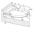
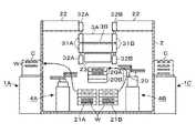
続いてアライメントモジュール20について説明する。アライメントモジュール20は、図2に示すようにロードロックモジュール3Bの下方後方寄りの位置に設けられている。図6に示すようにアライメントモジュール20は、各々2枚のウエハWを上下に保持して位置決めするアライメント機構20A、20Bが2つ、上下に設けられている。以降は上方側のアライメント機構を20A、下方側のアライメント機構を20Bとして記載する。アライメント機構20A、20Bは互いに同様に構成されており、代表してアライメント機構20Aについて説明する。アライメント機構20Aは、上下に間隔を空けて、平面視互いに重なり合うように設けられたウエハWの載置部111、112を備えている。 Next, the
図6に示すように、載置部111、112は各々図示しない回転軸を介して、筐体119に支持されている。筐体119は垂直部119Aと、垂直部119Aから上下2段に水平に延出された水平部119Bと、を備え、載置部111、112は夫々水平部119Bの下段、上段に支持されている。筐体119内には、図示しないプーリ、タイミングベルト、モータが設けられ、載置部111、112を回転軸を介して鉛直軸周りに回転させるように構成されている。 As shown in FIG. 6, the
図6中121は光検出部であり、当該光検出部121を構成する側方へ突出する2つの突片は、載置部111、112に各々載置されるウエハWの周縁部を上下方向に挟むように形成されている。この2つの突片が互いに対となる透過型の光センサとして構成されており、上側の突片は投光部、下側の突片は受光部をなし、投光部から受光部へ垂直下方に光を照射する。 In FIG. 6,
載置部111、112によるウエハWの回転中にこの光照射が行われウエハWの位置を検出する。当該検出を位置決めするという場合が有る。このように検出されるウエハWの位置には例えば、ウエハWの周縁部に形成された切り欠き(ノッチ)の位置及びウエハWの周縁部の位置が含まれる。このアライメント機構20A、20Bの載置部111、112は、いずれも第1の常圧搬送機構4A、第2の常圧搬送機構4Bの両方からウエハWが受け渡せるように常圧搬送室2の左右の中心部に配置されている。上記のように位置検出されたウエハWについて、第1の常圧搬送機構4A、第2の常圧搬送機構4Bが、支持フォーク部43上で所定の向きを向き、且つ所定の位置に位置するようにウエハWを受け取る(位置合せされる)。 This light irradiation is performed while the wafer W is being rotated by the mounting
また常圧搬送室2内におけるアライメントモジュール20の前方側には、冷却モジュール21A、21Bが左右に並んで設けられている。冷却モジュール21Aは常圧搬送室2の左右の中心よりも左側に、冷却モジュール21Bは常圧搬送室2の左右の中心よりも右側に夫々設けられている。冷却モジュール21A、21Bは、複数のウエハWを上下方向に載置する図示しない棚状の載置部を備え、載置部に載置されたウエハWは、後述のFFU23によって形成される気流に曝されて冷却される。左側の冷却モジュール21Aは、第1の常圧搬送機構4AによりウエハWの受け渡しが行われ、右側の冷却モジュール21Bは、第2の常圧搬送機構4BによりウエハWの受け渡しが行われる。
常圧搬送室2におけるロードロックモジュール3A、3Bを挟んだ左右の天井面には、常圧搬送室2内に下降気流を形成するためのファンフィルターユニット(FFU)22が設けられている。ロードロックモジュール3Bの下方領域は、常圧搬送室2の天井面に設けたFFU22によるダウンフローがロードロックモジュール3A、3Bに遮られるおそれがある。そのためロードロックモジュール3Bの下方の常圧搬送室2の天井部には、下方に当該常圧搬送室2の雰囲気を構成する気体を供給してダウンフローを形成するFFU23が設けられている。 Fan filter units (FFU) 22 for forming downward air currents in the normal
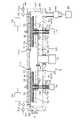
図1に示すようにロードロックモジュール3A、3Bの後方側には、内部を真空雰囲気とした真空搬送室9が接続されている。真空搬送室9は前後方向に伸びる概略矩形に構成され、前方側から見て真空搬送室9の左右に処理モジュール6が各々3台前後方向に並べて設けられている。 As shown in FIG. 1, a
また、図1に示すように真空搬送室9内には、多関節アームであるウエハWの真空搬送機構51が設けられている。真空搬送機構51は、基台52、水平に伸びる第1アーム53、水平に伸びる第2アーム54、ウエハ支持部55により構成されている。基台52は筐体41内の床において前後の中央において左寄りに設けられ、昇降自在に構成されている。第1アーム53は基部側が基台52上に設けられ、当該基台52上の垂直な旋回軸回りに旋回し、第2アーム54は基部側が第1アーム53の先端部上に設けられ、当該第1アーム53の先端部上の垂直な旋回軸回りに旋回する。ウエハ支持部55は、互いに平行に水平に伸びる2つの細長のへら状の支持部本体56と、支持部本体56の伸長方向に対して直交するように水平方向に伸び、2つの支持部本体56の基端を互いに接続する接続部57とを備えている。接続部57の長さ方向の中央部は第2アーム54の先端部上に設けられ、当該第2アーム54の先端部上の垂直な旋回軸回りに旋回する。 Further, as shown in FIG. 1, the
1つの支持部本体56の先端側と基端側とに互いに間隔を空けてウエハWの裏面が支持される。従って、真空搬送機構51のウエハ支持部55は、4枚のウエハWを一括して搬送することができる。そして図4に示すようにロードロックモジュール3A、3B内にウエハ支持部55を進入させ、ウエハWの受け渡し位置にてウエハ支持部55を昇降させたときに支持梁37とウエハ支持部55とが互いに干渉しないように配置されている。既述のように支持ピン35は、支持梁37の先端の下方に配置されることからウエハ支持部55と支持ピン35とも互いに干渉しないように配置されている。 The rear surface of the wafer W is supported on the distal end side and the proximal end side of one supporting portion
従ってウエハ支持部55に4枚のウエハWを支持させた状態で、ウエハ支持部55をウエハ受け渡し位置にて支持梁37よりも上方の位置から下方の位置に下降させることで、ウエハ支持部55が保持した4枚のウエハWが上段側のウエハ保持部38Aに一括して受け渡される。また4か所の上段側のウエハ保持部38Aにウエハを保持させた状態で、ウエハ支持部55をウエハ受け渡し位置にて支持梁37よりも下方の位置から上方の位置に上昇させることで、上段側のウエハ保持部38Aが保持した4枚のウエハWがウエハ支持部55に一括して受け渡される。また下段側のウエハ保持部38Bにおいても同様にウエハ支持部55と間で4枚のウエハWが一括して受け渡される。 Therefore, in a state in which four wafers W are supported by the
続いて処理モジュール6について、図7の縦断側面図を参照しながら説明する。6つの処理モジュール6は、ウエハWにプラズマALD(Atomic Layer Deposition)により成膜する成膜モジュールであり、6つとも同様に構成され、処理モジュール6間で互いに並行してウエハWの処理を行うことができる。処理モジュール6は、平面視、矩形の真空容器(処理容器)61を備えており(図1参照)、真空容器61の側壁にはゲートバルブGによって開閉されるウエハWの搬送口62が開口している。図7中の符号63は真空容器61の底面に開口した排気口であり、排気管64を介して真空ポンプ65に接続されている。図7中の符号66は排気管64に介設された圧力調整部である。 Next, the
真空容器61内には、搬送口62から見て、手前から奥に向けてウエハWを載置する載置部67A、67Bが列をなしてこの順に設けられ、この載置部67A、67Bの列は搬送口62から見て左右に並べられて設けられている。平面で見てウエハWは真空容器61内に2×2の行列状に、合計4枚載置され、この載置部67A、67Bの間隔に合わせて、ウエハ支持部55に支持される4枚のウエハWの間隔が設定されている。図7中の符号70は載置部67A、67Bに各々埋設されたヒーターであり、載置部67A、67Bに載置された各ウエハWを300℃~450℃に加熱する。
図7中の符号68は真空容器61の底面の中央部を貫通する支柱であり、当該支柱68の上端からは4つの支持アーム69が水平に放射状に伸びて、載置部67A、67Bを下方側から支持している。支柱68の下端側は、真空容器61の下方外側で昇降機構71に接続されており、当該昇降機構71により支柱68及び支持アーム69を介して載置部67A、67Bが、図7中に実線で示すウエハWの処理位置と鎖線で示すウエハWの受け渡し位置との間で昇降する。なお、図7中の72は、真空容器61内を気密に保つためのシール部材である。
各載置部67A、67Bには、3つの貫通孔73が形成されており、各貫通孔73には真空搬送機構51との間でウエハWを受け渡すために昇降する昇降ピン75が設けられ昇降機構74により昇降できるように構成されている。昇降ピン75は、各載置部67A、67BにウエハWを受け渡すときのウエハ支持部55と干渉しないように配置されている。既述のように各載置部67A、67Bは、ウエハ支持部55が保持する4枚のウエハWの位置に合わせて配置されている。従ってウエハ支持部55をウエハWの受け渡し位置に進入させて、ウエハ支持部55と昇降ピンとの協働作用にウエハWのウエハの受け渡しを行った時に4枚のウエハWをウエハ支持部55と、各載置部67A、67Bとの間で一括して受け渡すことができる。なお図7中の76は、真空容器61内の気密性を確保するためのベローズである。 Three through-
真空容器61の天井において載置部67A及び67Bの上方には、ガスシャワーヘッド77が絶縁部材77Aを介して各々設けられている。ガスシャワーヘッド77の下面は載置部67A、67Bに対向し、当該下面にはガス吐出孔78が多数、分散して配設されている。ガスシャワーヘッド7には整合器701を介して高周波電源702が接続される。また載置台67A、67B内には、図示しない下部電極が埋設されており、下部電極は、接地電位に接続されている。図7中の符号79はガス供給部であり、ガスシャワーヘッド77に四塩化チタン(TiCl4)、水素(H2)ガス、アンモニア(NH3)ガス、アルゴン(Ar)ガス、窒素(N2)ガスを夫々独立して供給し、これらのガスがガス吐出口78から各々吐出される。A
処理モジュール6によるウエハWの成膜処理について説明すると、受け渡し位置に位置する2つの載置部67A、2つの載置部67BにウエハWが載置された後、ヒーター70によりウエハWが加熱されると共に載置部67A、67Bが上昇して処理位置に移動する。次いで、ガスシャワーヘッド77から成膜用のガスとしてTiCl4ガスを供給し、ウエハWの表面に吸着させる。またウエハWに反応ガスとしてArガス及びH2ガスを供給する。さらに高周波電源702からガスシャワーヘッド7と載置台67A、67Bと内の下部電極との間に高周波電力を印加することにより供給された反応ガスを容量結合によりプラズマ化する。これによりTiCl4ガスとH2ガスとが活性化されて反応し、ウエハW表面にTi(チタン)の層が成膜される。各載置部67A、67B及び載置部67A、67Bに対応するガスシャワーヘッド77は、基板処理部を構成する。
このようにTiCl4ガスの吸着、Arガス及びH2ガスの供給と共に反応ガスのプラズマ化を順番に複数回繰り返す。これにより上記のTi層の形成が繰り返し行われて、所望の膜厚を有するTi膜が成膜される。The film forming process of the wafer W by the
In this way, the adsorption of TiCl4 gas, the supply of Ar gas and H2 gas, and the conversion of reaction gas into plasma are sequentially repeated several times. As a result, the formation of the Ti layer is repeated to form a Ti film having a desired film thickness.
真空処理装置は、図1に示すように真空処理装置内におけるウエハWの搬送、処理モジュール6における成膜処理のプロセス、ロードロックモジュール3A、3Bにおける雰囲気の切り替えを制御する制御部100を備えている。制御部100は例えば図示しないCPUと記憶部とを備えたコンピュータからなり、この記憶部には処理モジュール6における成膜処理のレシピや、当該真空処理装置において、常圧搬送機構4A、4B及び真空搬送機構51によるウエハWの搬送行うためのステップ(命令)群が組まれたプログラムが記録されている。このプログラムは、例えばハードディスク、コンパクトディスク、マグネットオプティカルディスク、メモリカードなどの記憶媒体に格納され、そこからコンピュータにインストールされる。 The vacuum processing apparatus, as shown in FIG. 1, includes a
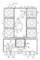
続いて上述の実施の形態の作用について説明する。図8~図13は、便宜上搬入出ポート1A~1Dのうちの搬入出ポート1A、1Cを夫々常圧搬送室2の左右に示すと共に、アライメントモジュール20及び冷却モジュール21A、21Bを上下に配置して示している。搬入出ポート1B、1Dの図示は、便宜上省略している。さらにこれらの図8~図13ではロードロックモジュール3A、3Bに最大4段にウエハWを示す。この4段のウエハWについて、上2段のウエハWはウエハ保持部38AのウエハW、つまりモジュールの上側に保持されたウエハWを示し、下2段のウエハWはウエハ保持部38BのウエハW、つまりモジュールの下側に保持されたウエハWを示している。また図10~13では、処理モジュール6にて処理を行った後のウエハWに斜線を付している。 Next, the operation of the above embodiment will be described. 8 to 13 show the loading/
図8に示すように未処理のウエハWを収容したキャリアCが搬入出ポート1A~1D上に載置されると、例えば前方から見て左側の搬入出ポート1A、1Bに載置されたキャリアC内の4枚の未処理ウエハWが、第1の常圧搬送機構4Aによって取り出され、アライメントモジュール20に搬送される。アライメントモジュール20は、このようにロードロックモジュール3A、3Bに搬送される処理前のウエハWが載置されることから処理前載置部に相当する。 As shown in FIG. 8, when the carrier C containing the unprocessed wafers W is placed on the loading/
そしてアライメントモジュール20にて4枚のウエハWの位置決めが行われる。次いで図9に示すようにアライメントモジュール20に載置されている4枚のウエハWのうち、例えば第2の常圧搬送機構4Bにより上方側のアライメント機構20Aに載置された2枚のウエハWを受け取る。また第1の常圧搬送機構4Aにより下方側のアライメント機構20Bの2枚のウエハWを受け取る。 Then, the four wafers W are positioned by the
さらに上側のロードロックモジュール3Aの左右のゲートバルブ32A、32Bが開かれる。そして第1の常圧搬送機構4Aが左側搬送路31Aからロードロックモジュール3Aに進入し、左側の列の2つの棚部38の上段側のウエハ保持部38Aに2枚のウエハWを受け渡す。また第2の常圧搬送機構4Bが右側搬送路31Bからロードロックモジュール3Aに進入し、右側の列の2つの棚部38の上段側のウエハ保持部38Aに2枚のウエハWを受け渡す。このように位置合わせを行った4枚のウエハWを第1の常圧搬送機構4Aと、第2の常圧搬送機構4Bと、で並行して夫々2枚づつ搬送することができるため、搬送にかかる時間が短くなる。 Furthermore, the left and
4枚のウエハWが上側のロードロックモジュール3Aに搬入されると、第1の常圧搬送機構4A及び第2の常圧搬送機構4Bがロードロックモジュール3Aから退出する。さらにロードロックモジュール3Aの左右のゲートバルブ32A、32Bを閉じ、ロードロックモジュール3A内を真空雰囲気に切り替える。そして真空雰囲気に切り替わったのち、上側のロードロックモジュール3Aの真空搬送室9側のゲートバルブ34を開き、真空搬送機構51をロードロックモジュール3Aに進入させる。この時ロードロックモジュール3Aの各棚部38の上段側のウエハ保持部38Aに載置されたウエハWの下方に真空搬送機構51のウエハ支持部55が進入する。さらにウエハ支持部55を上昇させることで各ウエハ保持部38Aに載置された、合わせて4枚のウエハWが一括してウエハ支持部55に掬い上げられる。 When the four wafers W are loaded into the upper load-
真空搬送室9の左右に接続された処理モジュール6を前方側から前段、中段、後段とすると、真空搬送機構51は、ウエハWを受け取ると、ウエハWを保持した状態で、処理モジュール6、例えば前方から見て右側の後段の処理モジュール6に進入する。真空搬送機構51に保持された各ウエハWは、夫々対応する載置部67A、67Bの上方に位置し、各載置部67A、67Bの昇降ピン75と真空搬送機構51と、の協働作用により4枚のウエハWが一括して対応する載置部67A、67Bに受け渡される。 Assuming that the
また常圧搬送室2側では、同様に後続のウエハWがアライメントモジュール20に搬送され、さらに下側のロードロックモジュール3Bに搬送される。そして同様にロードロックモジュール3B内を真空雰囲気に切り替え、真空搬送機構51によりロードロックモジュール3B内の4枚のウエハWが処理モジュール6に搬送される。
このようにウエハWを順次上側及び下側のロードロックモジュール3A、3Bに搬入し、真空搬送室9を介して、各処理モジュール6にウエハWを搬送する。そして各処理モジュール6にて、既述のようにウエハWの処理が行われる。Similarly, on the normal
In this manner, the wafers W are successively loaded into the upper and lower
各処理モジュール6にてウエハWの処理が行われた後、例えば前方側から見て右側後段の処理モジュール6のゲートバルブGが開かれる。そして真空搬送機構51により4つの載置部67A、67Bに載置されている処理済みのウエハWが一括して受け取られる。そして例えば上側のロードロックモジュール3Aのゲートバルブ34を開き、ウエハ支持部55をロードロックモジュール3Aに進入させ下段側のウエハ保持部38Bに4枚のウエハWを一括して受け渡す。その後ウエハ支持部55を真空搬送室9に退避させ、ゲートバルブ34を閉じ、ロードロックモジュール3A内の雰囲気を常圧雰囲気に切り替える。同様に例えば前方から見て左側後段の処理モジュール6の4枚のウエハWを下側のロードロックモジュール3Bの下段側のウエハ保持部38Bに受け渡す。さらにロードロックモジュール3B内の雰囲気を常圧雰囲気に切り替える。 After the wafer W is processed in each
この時常圧搬送室2においては、続いて処理を行うウエハWがキャリアCより取り出され、例えばアライメントモジュール20にて位置決めを行い待機した状態になっている。 At this time, in the normal
そして図10に示すように最初の未処理のウエハWをロードロックモジュール3Aに搬送したときと同様に、上側のロードロックモジュール3Aの左右のゲートバルブ32A、32Bを各々開く。さらに第1の常圧搬送機構4Aと、第2の常圧搬送機構4Bと、によりアライメントモジュール20の4枚の未処理のウエハWをロードロックモジュール3Aの上段側のウエハ保持部38Aに受け渡す。その後、図11に示すように第1の常圧搬送機構4Aは、ロードロックモジュール3Aの左側の列の下段側のウエハ保持部38Bに載置された2枚の処理済みウエハWを受け取る。また第2の常圧搬送機構4Bは、ロードロックモジュール3Aの右側の列の下段側のウエハ保持部38Bの2枚の処理済みウエハWを受け取る。 Then, as shown in FIG. 10, the left and
そして第1の常圧搬送機構4Aは、保持した処理済みウエハWを左側の冷却モジュール21Aに搬送し、第2の常圧搬送機構4Bは、保持した処理済みウエハWを右側の冷却モジュール21Bに搬送する。上側のロードロックモジュール3Aから4枚の処理済みウエハWが搬出された後、上側のロードロックモジュール3Aは、左右のゲートバルブ32A、32Bが閉じられ、真空雰囲気に切り替えられる。その後ロードロックモジュール3Aの4枚の未処理のウエハWは、既述のように真空搬送機構51により取り出され、所定の処理モジュール6に搬送される。 The first normal-
また冷却モジュール21A、21BにてウエハWを冷却している間に未処理ウエハWがアライメントモジュール20を介して、ロードロックモジュール3Bに搬送され、同様に第1の常圧搬送機構4A、及び第2の常圧搬送機構4Bによりロードロックモジュール3Bに収納されている処理済みウエハWが冷却モジュール21A、21Bに搬送される。このように冷却モジュール21A、21Bは、ロードロックモジュール3A、3Bから搬出されたウエハWを待機させることから処理後待機部といえ、冷却モジュール21A、21Bは、夫々第1の処理後待機部、第2の処理後待機部に相当する。 Further, while the wafer W is being cooled by the
その後ウエハWが十分に冷却されると、図12に示すように第1の常圧搬送機構4Aは、左側の冷却モジュール21Aから、冷却されたウエハWを受け取り、搬入出ポート1A、1BのキャリアCに戻す。また第2の常圧搬送機構4Bは、右側の冷却モジュール21Bから、冷却されたウエハWを受け取り、アライメントモジュール20に受け渡す。その後図13に示すようにアライメントモジュール20に載置された処理済みウエハWが第1の常圧搬送機構4Aにより搬入出ポート1A、1BのキャリアCに戻される。この時第2の常圧搬送機構4Bは、例えば冷却モジュール21Bにて冷却されたウエハWを順次アライメントモジュール20に搬送する。アライメントモジュール20は、処理後のウエハWが載置されることから処理後載置部に相当する。この例では、アライメントモジュール20は処理前載置部と、処理後載置部と、を兼用する。なお処理前載置部と、処理後載置部と、を各々個別に設けてもよい。 After that, when the wafer W is sufficiently cooled, the first normal
このように第1の常圧搬送機構4Aと、第2の常圧搬送機構4Bとにより、ロードロックモジュール3A、3Bに未処理ウエハWを搬送すると共に、ロードロックモジュール3A、3Bに搬送された処理済みウエハWを取り出しキャリアCに搬送する。 Thus, the unprocessed wafer W is transferred to the
また前方から見て右側の搬入出ポート1C、1Dに載置されたキャリアCに収納されたウエハWを取り出す場合には、第2の常圧搬送機構4BによりキャリアCからウエハWを取り出し、アライメントモジュール20に受け渡す。その後第1の常圧搬送機構4Aと、第2の常圧搬送機構4Bとにより、アライメントモジュール20から各ロードロックモジュール3A、3BにウエハWが搬送される。また処理済みウエハWをキャリアCに戻すにあたっては、第1の常圧搬送機構4A及び第2の常圧搬送機構4Bによりロードロックモジュール3Aから左側及び右側の冷却モジュール21A、21Bに夫々処理済みウエハWを搬送する。その後第1の常圧搬送機構4Aにより左側の冷却モジュール21Aにて冷却されたウエハWをアライメントモジュール20に搬送する。また第2の常圧搬送機構4Bは、右側の冷却モジュール21Bから右側の搬入出ポート1C、1Dに載置されたキャリアCにウエハWを戻すと共にアライメントモジュール20に搬送されたウエハWを右側の搬入出ポート1C、1Dに載置されたキャリアCに戻す。 When the wafer W stored in the carrier C mounted on the loading/
このように第1の常圧搬送機構4A及び第2の常圧搬送機構4BによりキャリアC、各ロードロックモジュール3A、3B、アライメントモジュール20及び冷却モジュール21A,21Bの間でウエハWを搬送し、順番にウエハWの処理を行う。
ところで、既述したように真空雰囲気としたロードロックモジュール3Aにおける真空搬送室9側のゲートバルブ34を開き、未処理のウエハWを搬出する際に、処理モジュール6にてウエハWの処理が終了している場合には、このロードロックモジュール3Aにおける未処理のウエハWが処理済みのウエハWに入れ替えられるように搬送が行われる。具体的にこの搬送動作を述べると、一の処理モジュール6で処理済みのウエハWを真空搬送機構51のウエハ支持部55が受け取り、既述のように当該ウエハWをロードロックモジュール3Aのウエハ保持部38Aに載置する。ロードロックモジュール3Aからウエハ支持部55が一旦退避し、ロードロックモジュール3Aが真空搬送室9に解放された状態のまま、真空搬送室9でウエハ支持部55の高さが変更される。さらに再度ロードロックモジュール3Aに進入して、ウエハ保持部38Bから未処理のウエハWを受け取り、一の処理モジュール6あるいは他の処理モジュール6へ当該ウエハWを搬送する。この処理モジュール6への搬送中に、ロードロックモジュール3Aは真空搬送室9から隔離され、大気雰囲気に変更される。ロードロックモジュール3Aを例にして説明したが、ロードロックモジュール3Bについても同様の搬送が行われる。Thus, the wafer W is transferred between the carrier C, the
By the way, as described above, when the
上述の真空処理装置によれば、処理モジュール6にてウエハWを平面視2×2の行列状に配置して一括処理して高スループット化を図るにあたり、ロードロックモジュール3A、3Bについても処理モジュール6と同様にウエハWを平面視行列状に配置するように構成している。そして、常圧搬送室2を、このロードロックモジュール3A、3Bの左右の一方側からロードロックモジュール3A、3Bの下方側を伸び左右の他方側に跨るように設け、常圧搬送室2におけるウエハWの搬送領域とロードロックモジュール3A、3Bとを上下にオーバーラップさせている。さらに、第1の常圧搬送機構4A、第2の常圧搬送機構4Bにより、ロードロックモジュール3A、3Bの左右で、搬入出ポート1A~1DのキャリアCに対してのウエハWの受け渡しが行えるようにしている。 According to the above-described vacuum processing apparatus, in order to achieve high throughput by arranging the wafers W in a matrix of 2×2 in plan view in the
このような構成によって、ロードロックモジュール3A、3Bに対して常圧搬送室2を前方向から接続するような場合に比べて平面で見たときに常圧搬送室2がロードロック3A、3Bの設けられた領域から前後方向に突出する突出量を小さく抑えることができる。それにより、装置全体の前後の幅が大きくなることを抑制し、装置のフットプリントを抑えることができる。さらにこのように装置を小型化しながら常圧搬送室2においてウエハWの搬送に必要なスペース及びアライメントモジュール20などの各モジュールの設置スペースを確保することができる。 With such a configuration, compared to the case where the normal
また、上記のように真空搬送装置には、第1の常圧搬送機構4A、第2の常圧搬送機構4Bが設けられる。それにより、搬入出ポート1A、1BのキャリアCとロードロックモジュール3A、3Bとの間でのウエハWの搬送と、搬入出ポート1A、1BのキャリアCとロードロックモジュール3A、3Bとの間でのウエハWの搬送とを並行して行うことができるため、より高いスループットを得ることができる。 Further, as described above, the vacuum transfer device is provided with the first normal
ところで上記の真空搬送装置では、常圧搬送室2におけるロードロックモジュール3A、3Bの下方の搬送路に各種モジュールが設けられるので、常圧搬送室2のロードロックモジュール3A、3Bからの左右の突出量がより確実に抑制されている。また、このモジュールを介してロードロックモジュール3A、3Bの右側(左側)と、常圧搬送室2の左側(右側)の搬入出ポート1のキャリアCとの間でウエハWの受け渡しが行われる。従って、各搬入出ポート1A~1Dとロードロックモジュール3A、3Bとの間でウエハWを受け渡すにあたり、第1の常圧搬送機構4A、第2の常圧搬送機構4Bはロードロックモジュール3A、3Bの下側を横断して移動する必要がない。また第1の常圧搬送機構4A、第2の常圧搬送機構4Bは、各々対応する左側搬送路31A、右側搬送路31Bから見て奥側の棚部38までアームを伸ばす必要がない。
従って、第1の常圧搬送機構4A及び第2の常圧搬送機構4Bの支持フォーク部43及び上段アーム部42、下段アーム部41を短くすることができる。そのため、第1の常圧搬送機構4A及び第2の常圧搬送機構4Bの旋回半径を小さくすることができ、常圧搬送室2のフットプリントを小さくし、従って装置全体のフットプリントの増加をより確実に抑制することができる。By the way, in the above vacuum transfer apparatus, since various modules are provided in the transfer path below the
Therefore, the
また本実施の形態に係る真空処理装置は、搬入出ポート1を常圧搬送室2の前方におけるロードロックモジュール3A、3Bの左右方向に外れた位置に設けている。それによりロードロックモジュール3A、3Bを構成する筐体30の前方側の側壁が露出している。この側壁に図4で説明したように、筐体30に給気及び排気を行う配管302、304を接続し、搬送ポート1A、1Bと、1C、1Dとの間のスペースを利用してこれらの配管を引き回すことができる。従って、装置のフットプリントの増大をより確実に防ぐことができるし、例えば常圧搬送室2内にて配管を引き回すような必要が無いので、装置構成を簡素にすることができる。 Further, in the vacuum processing apparatus according to the present embodiment, the loading/unloading
またアライメントモジュール20を設けることは必須ではない。さらには、アライメントモジュール20に代えて、第1の常圧搬送機構4A及び第2の常圧搬送機構4BのいずれからもウエハWを受け渡すことができるウエハWの載置部を設けてもよい。つまり、ウエハWの位置決めを行わず、単にウエハWの載置のみを行うモジュールを設けてもよい。そのように位置決めを行わない場合、例えば第1の常圧搬送機構4A及び第2の常圧搬送機構4Bの支持フォーク部43について、保持したウエハWの周縁を周縁側から中心側に向けて押圧する機構を備えるように構成する。その押圧機構によって、ウエハWの中心位置がウエハW保持部43の所定の位置に位置するようにしてもよい。
また冷却モジュール21A、21Bも必須ではない。その場合には例えば、ロードロックモジュール3A、3Bにて載置されたウエハWを冷却できるように構成してもよい。具体的には、例えばロードロックモジュール3A、3BにウエハW保持棚38の代わりに冷媒が流通するステージを設けて、当該ステージに載置されたウエハWが冷却されるようにしてもよい。Also, providing the
Also, the
なお、上記の真空搬送装置では、前後に見たときに処理モジュール6が常圧搬送室2と重なるように設けられているため、装置の左右の幅が抑えられている。また搬入出ポート1A~1Dが、常圧搬送室2の前方に設けられているため、装置の左右方向の幅がより抑えられ、それにより装置全体のフットプリントがより抑えられている。ただし、搬入出ポート1A~1Dを常圧搬送室2の左右に設けてもよい。また搬入出ポート1A~1Dは、常圧搬送室2の左右に各々2台設けた構成に限定されず、例えば各々3台以上設けられていてもよい。
また第1及び第2の常圧搬送機構4A、4Bは、鉛直方向に伸びるガイドレールに沿って昇降するように構成してもよい。その場合例えば第1の常圧搬送機構4Aを支持するガイドレールを常圧搬送室2における後方側の左端に設け、第2の常圧搬送機構4Bを支持するガイドレールを常圧搬送室2における後方側の右端に設けるようにすればよい。そして基台40をガイドレールに沿って昇降するように構成し基台40に下段アーム部41を回動自在に設ければよい。In the above-described vacuum transfer apparatus, since the
Also, the first and second normal-
また冷却モジュール21A、21Bは、例えばウエハWが載置される載置台に冷却水などの冷媒が通流されることで当該ウエハWを冷却する構成であってもよい。また例えば冷却モジュールを1台とし第1の常圧搬送機構4A及び第2の常圧搬送機構4BのどちらからもウエハWを受け渡せるように構成してもよい。このように冷却モジュールを第1の常圧搬送機構4A及び第2の常圧搬送機構4BのどちらからもウエハWを受け渡せるように構成する場合には、冷却モジュールにて冷却したウエハWをアライメントモジュール20を通過させずにキャリアCに戻すことができ、ウエハWの搬送時間を短くすることができる。 Further, the
またロードロックモジュール3A、3Bは2枚のウエハWを左右に並べて配置する構成でも良い。さらに常圧搬送室2をロードロックモジュール3A、3Bの左右一方側からロードロックモジュール3A、3Bの上方側を伸び左右他方側に跨るように設けてもよい。 Also, the
また前方から見て左側の棚部38には、搬入出ポート1A、1BのキャリアCから取り出したウエハWを受け渡し、前方から見て右側の棚部38には、搬入出ポート1C、1DのキャリアCから取り出したウエハWを受け渡すようにしてもよい。
例えば第1の常圧搬送機構4Aにより搬入出ポート1A、1BのキャリアCから取り出し、アライメントモジュール20に搬送する。さらに当該アライメントモジュール20に搬送したウエハWを第1の常圧搬送機構4Aにより受け取り、ロードロックモジュール3Aの前方から見て左側の棚部38に受け渡す。そして第2の常圧搬送機構4Bにより搬入出ポート1C、1DのキャリアCから取り出し、アライメントモジュール20に搬送する。さらに当該アライメントモジュール20に搬送したウエハWを第2の常圧搬送機構4Bにより受け取り、ロードロックモジュール3Aの前方から見て右側の棚部38に受け渡す。このような例も本開示の範囲に含まれる。Wafers W unloaded from the carriers C of the loading/
For example, it is taken out from the carriers C of the loading/
同様に、ロードロックモジュール3A、3Bの左側の棚部38から受け取られたウエハWが、左側の冷却モジュール21Aに搬送された後、左側の搬入出ポート1A、1BのキャリアCに戻されても良い。そして、ロードロックモジュール3A、3Bの右側の棚部38から受け取られたウエハWが、右側の冷却モジュール21Bに搬送された後、右側の搬入出ポート1C、1DのキャリアCに戻されても良い。つまり、常圧搬送室2において、ロードロックモジュール3A、3Bの右側(左側)の搬送路からロードロックモジュール3A、3Bの下方の搬送領域を跨いで左側(右側)の搬送路にウエハWが移動するという搬送が行われることには限られない。 Similarly, even if the wafer W received from the
さらに一つの筐体30の左右にゲートバルブ32A、32Bを設けたときに、左右のゲートバルブ32A、32Bを開けるタイミングが同時でない場合には、筐体30内に気流が生じパーティクルが発生するおそれがある。そのためロードロックモジュール3A、3Bは、前記筐体30の内部が左側のウエハ保持部38A、Bが配置される空間と、右側のウエハ保持部38A、Bが配置される空間と、が仕切られていてもよい。そして各々仕切られた空間毎に常圧雰囲気と真空雰囲気とに切り替えることができるように構成してもよい。なお前記仕切られた空間が互いに左右に離間して配置される場合も筐体30の内部が左右の空間に仕切られているに含まれる。 Furthermore, when the
また本開示の真空搬送機構51は、ウエハ支持部55を互いに平行に水平に伸びる2つの細長のへら状の支持部本体56と、支持部本体56の伸長方向に対して直交するように水平方向に伸び、2つの支持部本体56の基端を互いに接続する接続部57とで構成している。そのため筐体30の内部を左右に仕切るように構成したときにも、2つの支持部本体56を夫々筐体30内にて仕切られた右側の空間と左側の空間とに同時に進入させることができる。従って左側のウエハ保持部38A、B及び右側のウエハ保持部38A、Bと、の間で一括してウエハWの受け渡しを行うことができる。
また常圧搬送室2は、内部雰囲気として窒素ガスが充填されていてもよい。さらに真空搬送室9に接続する処理モジュール6は、成膜装置に限らず、エッチング装置やアニール装置、あるいは、これらの組み合わせでも良い。In addition, the
Further, the normal
[第2の実施の形態]
また常圧搬送室2に常圧搬送機構を1台設けた構成でも良い。図14、15に示す例では、ロードロックモジュール3A、3Bを常圧搬送室2の後方寄りに設けている。この例では、常圧搬送機構4Cを常圧搬送室におけるロードロックモジュール3A、3Bの前方側に設けている。さらに詳しく説明すると、常圧搬送室2を構成する筐体200の前方壁が、ロードロックモジュール3A、3Bの前方壁よりも前方に位置している。そして、これらの前方壁と前方壁との間のスペースは、常圧搬送機構4Cが移動する移動路として構成されている。
常圧搬送機構4Cは、第1及び第2の常圧搬送機構4A、4Bと同様に下段部材400A、中段部材400B及び上段部材400Cを含み、伸縮自在に構成された基台400を備えている。基台400の上段部材400Cには、下段アーム部401、中段アーム部402、上段アーム部403、ウエハWを保持する支持フォーク404の順に連結された多関節アームが回動自在に設けられている。[Second embodiment]
Alternatively, the normal
The normal-
またこの例では、ロードロックモジュール3A、3Bの下方にアライメントモジュール20、冷却モジュール21A、21Bを設けていないが、図1~3に示す真空処理装置と同様にアライメントモジュール20及び冷却モジュール21A、21Bを備えた構成でも良い。
この真空処理装置においては、左側に配置されたキャリアCからから取り出したウエハWをロードロックモジュール3A、3Bに搬送するにあたって、ロードロックモジュール3A、3Bの左側の棚部38にウエハWを受け渡すときには、常圧搬送機構4Cを左側の搬送路31Aからロードロックモジュール3A、3Bに進入させて受け渡す。また左側に配置されたキャリアCから、ロードロックモジュール3A、3Bにおける前方側から見て右側の棚部38にウエハWを受け渡すときには、キャリアCからウエハWを受け取った常圧搬送機構4Cをロードロックモジュール3A、3Bの下方側を通過させロードロックモジュール3A、3Bの右側に移動させる。さらに常圧搬送機構4Cを右側の搬送路31Bからロードロックモジュール3A、3Bに進入させて右側の棚部38に受け渡す。In this example, the
In this vacuum processing apparatus, when the wafer W is taken out from the carrier C arranged on the left side and transferred to the
このような真空処理装置においても、ウエハWを左右2列、前後2行に配置するロードロックモジュール3A、3Bが常圧搬送室2のウエハWの搬送領域と上下に重なるように配置されるため、装置のフットプリントを抑制することができる。また、常圧搬送室2の搬送機構としては常圧搬送機構4Cのみが設けられるため、装置の製造コストを抑えることができる。 In such a vacuum processing apparatus as well, the
以上に検討したように、今回開示された実施形態はすべての点で例示であって制限的なものではないと考えられるべきである。上記の実施形態は、添付の請求の範囲及びその主旨を逸脱することなく、様々な形態で省略、置換、変更されてもよい。 As discussed above, the embodiments disclosed this time should be considered illustrative and not restrictive in all respects. The embodiments described above may be omitted, substituted, or modified in various ways without departing from the scope and spirit of the appended claims.
1 搬入出ポート
2 常圧搬送室
3A、3B ロードロックモジュール
6 処理モジュール
4A 第1の常圧搬送機構
4B 第2の常圧搬送機構
38A、38B ウエハ保持部
9 真空搬送室
51 真空搬送機構
20 アライメントモジュール
21A、21B 冷却モジュール
W ウエハ1 loading/unloading
Claims (19)
Translated fromJapanese前記筐体の後方に接続され、前記第2の基板搬送口が開口する真空雰囲気の真空搬送室と、
前記真空搬送室に接続され、前記基板を真空処理するための処理モジュールと、
前記ロードロックモジュールと前記搬送室と前記処理モジュールとの間で前記基板を搬送する真空搬送機構と、
前記各第1の基板搬送口が開口するように前記筐体の上方または下方を跨いで当該筐体の左右の一方から他方へ亘って形成され、当該筐体に重なる前記基板の搬送領域である積層搬送領域を備える常圧雰囲気の常圧搬送室と、
前記常圧搬送室の外側の左右に各々設けられた、前記基板を格納する搬送容器を搬入出する複数の搬入出ポートと、
前記積層搬送領域を経由して前記各搬入出ポートに搬入された前記搬送容器と前記各基板保持部との間で前記基板を搬送する常圧搬送機構と、
を備えた真空処理装置。A housing whose interior is switchable between a normal pressure atmosphere and a vacuum atmosphere, and is provided with freely openable and closable first substrate transfer ports formed on the left and right sides and a freely openable and closable second substrate transfer port formed at the rear. a load lock module comprising a body, and a plurality of substrate holding portions each holding left and right substrates in the housing;
a vacuum transfer chamber connected to the rear of the housing and having a vacuum atmosphere in which the second substrate transfer port is open;
a processing module connected to the vacuum transfer chamber for vacuum processing the substrate;
a vacuum transfer mechanism that transfers the substrate between the load lock module, the transfer chamber, and the processing module;
A transfer area for the substrate that is formed from one to the other of the left and right sides of the housing so as to straddle the upper side or the lower side of the housing so that each of the first substrate transfer ports is open, and that overlaps with the housing. a normal-pressure transfer chamber with a normal-pressure atmosphere having a stacking transfer area;
a plurality of loading/unloading ports for loading/unloading the transfer containers for storing the substrates, respectively provided on the left and right sides of the normal pressure transfer chamber;
a normal-pressure transport mechanism for transporting the substrate between the transport container loaded into each of the loading/unloading ports via the stacking transport area and each of the substrate holding units;
Vacuum processing equipment with
左右の一方の前記搬入出ポートと、左右の他方の前記基板保持部との間で前記積層搬送領域を経由して、前記基板の受け渡しを行う請求項1記載の真空処理装置。The normal pressure transfer mechanism is
2. The vacuum processing apparatus according to claim 1, wherein the substrates are transferred between the loading/unloading port on one of the left and right sides and the substrate holding portion on the other of the left and right sides via the stacking transfer area.
前記筐体に対して左右の一方に設けられ、前記複数の基板保持部のうち左右の一方の基板保持部に対する前記基板の受け渡しのみを行うと共に前記積層搬送領域に設けられて前記基板を載置する載置部に対して前記基板を受け渡す第1の常圧搬送機構と、
前記筐体に対して左右の他方に設けられ、前記複数の基板保持部のうち左右の他方の基板保持部に対する前記基板の受け渡しのみを行うと共に前記載置部に対して前記基板を受け渡す第2の常圧搬送機構と、
を備える請求項1ないし11のいずれか一つに記載の真空処理装置。The normal pressure transfer mechanism is
provided on one of the left and right sides of the housing for only transferring the substrate to one of the left and right substrate holding portions among the plurality of substrate holding portions;a first normal-pressure transfer mechanism for transferring the substrate to the mounting portion;
A second substrate that is provided on the other of the left and right sides of the housing and that only transfers the substrate to the other left and right substrate holding portions among the plurality of substrate holding portions and that transfers the substrate to the mounting portion. 2 normal pressure transport mechanism;
The vacuum processing apparatus according to any one of claims 1 to 11, comprising:
当該処理前載置部に対して、前記第1の常圧搬送機構及び前記第2の常圧搬送機構が前記基板を受け渡し可能であり、
前記第1の常圧搬送機構または第2の常圧搬送機構により当該処理前載置部に順次搬送された基板は、前記第1の常圧搬送機構、第2の常圧搬送機構の各々により前記ロードロックモジュールに搬送される請求項12記載の真空処理装置。The mounting section includes a pre-processing mounting section for mounting the unprocessed substrate to be transported to the load lock module,
The first normal-pressure transport mechanism and the second normal-pressure transport mechanism can transfer the substrate to the pre-processing placement unit,
The substrates sequentially transported to the pre-processing platform by the first normal-pressure transport mechanism or the second normal-pressure transport mechanism are transferred by the first normal-pressure transport mechanism and the second normal-pressure transport mechanism respectively. 13. The vacuum processing apparatus of claim 12, which is transported to the load lock module.
前記第1の常圧搬送機構及び第2の常圧搬送機構から受け渡された処理済みの前記基板を載置する処理後載置部と、を含み、
前記処理後待機部は、前記第1の常圧搬送機構及び前記第2の常圧搬送機構のうち第1の常圧搬送機構のみから前記基板が受け渡される第1の処理後待機部と、
前記第1の常圧搬送機構及び前記第2の常圧搬送機構のうち前記第2の常圧搬送機構のみから前記基板が受け渡される第2の処理後待機部と、を含み、
前記第1の処理後待機部及び前記第2の処理後待機部のうちの一方から前記処理後載置部に前記基板が搬送され、前記第1の常圧搬送機構及び第2の常圧搬送機構のうち当該処理後載置部への搬送に用いた常圧搬送機構とは別の常圧搬送機構により、当該基板を前記搬送容器に搬送する請求項12または13記載の真空処理装置。The mounting unit includesa post-processing waiting unit for waiting the substrate unloaded from the load lock module ;
a post-processing placement unit for placing the processed substrates transferred from the first normal-pressure transport mechanism and the second normal-pressure transport mechanism;
The post-processing standby section includes a first post-processing standby section in which the substrate is transferred only from the first normal-pressure transport mechanism out of the first normal-pressure transport mechanism and the second normal-pressure transport mechanism;
a second post-processing standby section in which the substrate is transferred only from the second normal-pressure transport mechanism out of the first normal-pressure transport mechanism and the second normal-pressure transport mechanism;
The substrate is transported from one of the first post-processing waiting section and the second post-processing waiting section to the post-processing placement section, and is transported by the first normal pressure transport mechanism and the second normal pressure transport mechanism. 14. The vacuum processing apparatus according to claim 12 or 13, wherein the substrate is transferred to the transfer container by a normal pressure transfer mechanism different from the normal pressure transfer mechanism used for transfer to the post-treatment receiver .
前記常圧搬送機構は、前記各搬入出ポートに共用される請求項1ないし11のいずれか一つに記載の真空処理装置。The plurality of loading/unloading ports are provided on the left and right sides of the left and right central portions of the housing,
12. The vacuum processing apparatus according to any one of claims 1 to 11, wherein the normal pressure transfer mechanism is shared by each of the loading/unloading ports.
上側及び下側の前記基板保持部のうちの他方の基板保持部には、前記真空搬送室から前記ロードロックモジュールに搬送された基板が保持される請求項17記載の真空処理装置。one of the upper and lower substrate holders holds a substrate transferred from the normal pressure transfer chamber to the load lock module;
18. The vacuum processing apparatus according to claim 17, wherein the substrate transferred from the vacuum transfer chamber to the load lock module is held by the other substrate holding part of the upper and lower substrate holding parts.
前記各第1の基板搬送口が開口するように前記筐体の上方または下方を跨いで当該筐体の左右の一方から他方へ亘って形成される常圧雰囲気の常圧搬送室の外側の左右に各々設けられた複数の搬入出ポートに、前記基板を格納する搬送容器を搬入出する工程と、
常圧搬送機構により、前記常圧搬送室において筐体に重なる前記基板の搬送領域である積層搬送領域を経由して前記各搬入出ポートに搬入された前記搬送容器と前記各基板保持部との間で前記基板を搬送する工程と、
真空搬送機構により、前記筐体の後方に接続され、前記第2の基板搬送口が開口する真空雰囲気の真空搬送室と、前記真空搬送室に接続され、前記基板を真空処理するための処理モジュールと、前記ロードロックモジュールとの間で前記基板を搬送する工程と、
を備えた基板搬送方法。A housing whose interior is switchable between a normal pressure atmosphere and a vacuum atmosphere, and is provided with freely openable and closable first substrate transfer ports formed on the left and right sides and a freely openable and closable second substrate transfer port formed at the rear. A substrate transport method for transporting the substrate in a vacuum processing apparatus equipped with a load lock module having a body and a plurality of substrate holding parts each holding the substrate on the left and right sides in the housing,
Left and right sides of the outside of a normal pressure transfer chamber with a normal pressure atmosphere formed from one to the other of the left and right sides of the case straddling the upper or lower part of the case so that each of the first substrate transfer ports opens loading and unloading transport containers for storing the substrates into and out of a plurality of loading and unloading ports respectively provided in the
By the normal pressure transfer mechanism, the transport container and the substrate holders are transported into the load/unload ports via the stacked transport area, which is the transport area of the substrates overlapping the housing in the normal pressure transport chamber. transporting the substrate between;
A vacuum transfer chamber connected to the rear of the housing by a vacuum transfer mechanism and having a vacuum atmosphere in which the second substrate transfer port is open; and a processing module connected to the vacuum transfer chamber for performing vacuum processing on the substrate. and transferring the substrate to and from the load lock module;
A substrate transfer method comprising:
Priority Applications (6)
| Application Number | Priority Date | Filing Date | Title |
|---|---|---|---|
| JP2018177838AJP7210960B2 (en) | 2018-09-21 | 2018-09-21 | Vacuum processing apparatus and substrate transfer method |
| US17/276,391US11688619B2 (en) | 2018-09-21 | 2019-09-10 | Vacuum processing apparatus and substrate transfer method |
| CN201980059827.0ACN112689891B (en) | 2018-09-21 | 2019-09-10 | Vacuum processing apparatus and substrate conveying method |
| KR1020217010580AKR102491212B1 (en) | 2018-09-21 | 2019-09-10 | Vacuum processing device and substrate transfer method |
| PCT/JP2019/035548WO2020059574A1 (en) | 2018-09-21 | 2019-09-10 | Vacuum process device and substrate transporting method |
| TW108133751ATWI844566B (en) | 2018-09-21 | 2019-09-19 | Vacuum processing device and substrate transport method |
Applications Claiming Priority (1)
| Application Number | Priority Date | Filing Date | Title |
|---|---|---|---|
| JP2018177838AJP7210960B2 (en) | 2018-09-21 | 2018-09-21 | Vacuum processing apparatus and substrate transfer method |
Publications (2)
| Publication Number | Publication Date |
|---|---|
| JP2020053418A JP2020053418A (en) | 2020-04-02 |
| JP7210960B2true JP7210960B2 (en) | 2023-01-24 |
Family
ID=69887451
Family Applications (1)
| Application Number | Title | Priority Date | Filing Date |
|---|---|---|---|
| JP2018177838AActiveJP7210960B2 (en) | 2018-09-21 | 2018-09-21 | Vacuum processing apparatus and substrate transfer method |
Country Status (6)
| Country | Link |
|---|---|
| US (1) | US11688619B2 (en) |
| JP (1) | JP7210960B2 (en) |
| KR (1) | KR102491212B1 (en) |
| CN (1) | CN112689891B (en) |
| TW (1) | TWI844566B (en) |
| WO (1) | WO2020059574A1 (en) |
Families Citing this family (9)
| Publication number | Priority date | Publication date | Assignee | Title |
|---|---|---|---|---|
| KR102833850B1 (en)* | 2020-03-24 | 2025-07-14 | 주식회사 원익아이피에스 | Transfer Robot and Substrate Processing apparatus having the same |
| JP7445509B2 (en)* | 2020-04-27 | 2024-03-07 | 東京エレクトロン株式会社 | Substrate processing equipment and substrate transport method |
| US11581203B2 (en)* | 2020-09-02 | 2023-02-14 | Applied Materials, Inc. | Systems for integrating load locks into a factory interface footprint space |
| US12159802B2 (en) | 2021-03-04 | 2024-12-03 | Applied Materials, Inc. | Shortened load port for factory interface |
| KR20230037990A (en) | 2021-09-10 | 2023-03-17 | 삼성전자주식회사 | Wafer processing device comprising efem and method for processing wafer |
| US12142508B2 (en)* | 2021-10-12 | 2024-11-12 | Applied Materials, Inc. | Factory interface robots usable with integrated load locks |
| CN116180022B (en)* | 2021-11-19 | 2025-05-23 | 芝浦机械电子装置株式会社 | Supply device and film forming device |
| TWI848544B (en)* | 2023-02-04 | 2024-07-11 | 矽品精密工業股份有限公司 | Working system for semiconductor packaging process and running method thereof |
| WO2025105234A1 (en)* | 2023-11-17 | 2025-05-22 | 東京エレクトロン株式会社 | Transport system and transport method |
Citations (3)
| Publication number | Priority date | Publication date | Assignee | Title |
|---|---|---|---|---|
| JP2000012647A (en) | 1998-06-19 | 2000-01-14 | Sumitomo Eaton Noba Kk | Device and method for carrying wafer |
| JP2007533167A (en) | 2004-04-16 | 2007-11-15 | アクセリス テクノロジーズ インコーポレーテッド | Workpiece processing system |
| JP2018014427A (en) | 2016-07-21 | 2018-01-25 | 株式会社日立国際電気 | Substrate processing device, method for manufacturing semiconductor device, and program |
Family Cites Families (38)
| Publication number | Priority date | Publication date | Assignee | Title |
|---|---|---|---|---|
| JP4048387B2 (en)* | 1997-09-10 | 2008-02-20 | 東京エレクトロン株式会社 | Load lock mechanism and processing device |
| JP2007273620A (en)* | 2006-03-30 | 2007-10-18 | Tokyo Electron Ltd | Substrate transport apparatus and substrate processing apparatus |
| US20080105201A1 (en)* | 2006-11-03 | 2008-05-08 | Applied Materials, Inc. | Substrate support components having quartz contact tips |
| US7949425B2 (en)* | 2006-12-06 | 2011-05-24 | Axcelis Technologies, Inc. | High throughput wafer notch aligner |
| US20090179366A1 (en)* | 2008-01-16 | 2009-07-16 | Sokudo Co., Ltd. | Apparatus for supporting a substrate during semiconductor processing operations |
| JP4983745B2 (en)* | 2008-08-01 | 2012-07-25 | 東京エレクトロン株式会社 | Pressure adjusting device, treatment system using the same, and pressure adjusting method |
| JP5548430B2 (en)* | 2008-11-26 | 2014-07-16 | 株式会社日立国際電気 | Substrate processing apparatus and semiconductor device manufacturing method |
| JP2010141000A (en)* | 2008-12-10 | 2010-06-24 | Hitachi Kokusai Electric Inc | Substrate processing apparatus |
| JP2011049507A (en)* | 2009-08-29 | 2011-03-10 | Tokyo Electron Ltd | Load lock device, and processing system |
| JP5549441B2 (en)* | 2010-01-14 | 2014-07-16 | 東京エレクトロン株式会社 | Holder mechanism, load lock device, processing device, and transport mechanism |
| JP5526988B2 (en)* | 2010-04-28 | 2014-06-18 | 東京エレクトロン株式会社 | Substrate processing apparatus and substrate processing system |
| JP2012039075A (en)* | 2010-07-13 | 2012-02-23 | Tokyo Electron Ltd | Vacuum processing apparatus |
| JP5503006B2 (en)* | 2010-08-06 | 2014-05-28 | 東京エレクトロン株式会社 | Substrate processing system, transfer module, substrate processing method, and semiconductor device manufacturing method |
| WO2012099064A1 (en)* | 2011-01-18 | 2012-07-26 | 株式会社日立国際電気 | Substrate processing apparatus, substrate supporting tool, and semiconductor device manufacturing method |
| US9443749B2 (en)* | 2011-01-20 | 2016-09-13 | Tokyo Electron Limited | Vacuum processing apparatus |
| JP5883232B2 (en)* | 2011-03-26 | 2016-03-09 | 東京エレクトロン株式会社 | Substrate processing equipment |
| JP6003011B2 (en)* | 2011-03-31 | 2016-10-05 | 東京エレクトロン株式会社 | Substrate processing equipment |
| JP5686261B2 (en)* | 2011-07-29 | 2015-03-18 | セメス株式会社SEMES CO., Ltd | Substrate processing apparatus and substrate processing method |
| EP2791034B1 (en)* | 2011-12-16 | 2021-01-27 | Brooks Automation, Inc. | Transport apparatus |
| KR102359364B1 (en)* | 2012-02-10 | 2022-02-07 | 브룩스 오토메이션 인코퍼레이티드 | Substrate Processing Apparatus |
| JP2013171872A (en) | 2012-02-17 | 2013-09-02 | Tokyo Electron Ltd | Substrate processing device and substrate processing method |
| JP2013251416A (en)* | 2012-05-31 | 2013-12-12 | Tokyo Electron Ltd | Production method of lamination film and vacuum processing apparatus |
| JP6358856B2 (en)* | 2014-05-29 | 2018-07-18 | 東京エレクトロン株式会社 | Electrostatic adsorption device and cooling processing device |
| JP2016004834A (en)* | 2014-06-13 | 2016-01-12 | 東京エレクトロン株式会社 | Vacuum processing device |
| US10332769B2 (en)* | 2016-01-15 | 2019-06-25 | Taiwan Semiconductor Manufacturing Co., Ltd. | Semiconductor processing station, semiconductor process and method of operating semiconductor processing station |
| JP2018006534A (en)* | 2016-06-30 | 2018-01-11 | 東京エレクトロン株式会社 | Deposition device, deposition method and storage medium |
| JP6747136B2 (en)* | 2016-07-22 | 2020-08-26 | 東京エレクトロン株式会社 | Substrate processing equipment |
| JP6739285B2 (en)* | 2016-08-24 | 2020-08-12 | 東京エレクトロン株式会社 | Substrate processing equipment |
| JP6863780B2 (en)* | 2017-03-10 | 2021-04-21 | 株式会社Screenホールディングス | Heat treatment method and heat treatment equipment |
| JP2018174186A (en)* | 2017-03-31 | 2018-11-08 | 東京エレクトロン株式会社 | Substrate processing apparatus |
| JP6881010B2 (en)* | 2017-05-11 | 2021-06-02 | 東京エレクトロン株式会社 | Vacuum processing equipment |
| KR102030068B1 (en)* | 2017-10-12 | 2019-10-08 | 세메스 주식회사 | Substrate treating apparatus and substrate treating method |
| JP7032955B2 (en)* | 2018-02-28 | 2022-03-09 | 株式会社Screenホールディングス | Heat treatment method |
| US11043403B2 (en)* | 2018-04-06 | 2021-06-22 | Semes Co., Ltd. | Substrate support unit and substrate processing apparatus having the same including reflective member configured to reflect light toward substrate |
| JP7014055B2 (en)* | 2018-06-15 | 2022-02-01 | 東京エレクトロン株式会社 | Vacuum processing equipment, vacuum processing system, and vacuum processing method |
| JP7183635B2 (en)* | 2018-08-31 | 2022-12-06 | 東京エレクトロン株式会社 | SUBSTRATE TRANSFER MECHANISM, SUBSTRATE PROCESSING APPARATUS AND SUBSTRATE TRANSFER METHOD |
| KR20200078116A (en)* | 2018-12-21 | 2020-07-01 | 세메스 주식회사 | Apparatus for treating substrate and method for treating apparatus |
| US11501993B2 (en)* | 2019-07-29 | 2022-11-15 | Applied Materials, Inc. | Semiconductor substrate supports with improved high temperature chucking |
- 2018
- 2018-09-21JPJP2018177838Apatent/JP7210960B2/enactiveActive
- 2019
- 2019-09-10KRKR1020217010580Apatent/KR102491212B1/enactiveActive
- 2019-09-10WOPCT/JP2019/035548patent/WO2020059574A1/ennot_activeCeased
- 2019-09-10USUS17/276,391patent/US11688619B2/enactiveActive
- 2019-09-10CNCN201980059827.0Apatent/CN112689891B/enactiveActive
- 2019-09-19TWTW108133751Apatent/TWI844566B/enactive
Patent Citations (3)
| Publication number | Priority date | Publication date | Assignee | Title |
|---|---|---|---|---|
| JP2000012647A (en) | 1998-06-19 | 2000-01-14 | Sumitomo Eaton Noba Kk | Device and method for carrying wafer |
| JP2007533167A (en) | 2004-04-16 | 2007-11-15 | アクセリス テクノロジーズ インコーポレーテッド | Workpiece processing system |
| JP2018014427A (en) | 2016-07-21 | 2018-01-25 | 株式会社日立国際電気 | Substrate processing device, method for manufacturing semiconductor device, and program |
Also Published As
| Publication number | Publication date |
|---|---|
| TWI844566B (en) | 2024-06-11 |
| CN112689891B (en) | 2024-07-26 |
| TW202029390A (en) | 2020-08-01 |
| KR20210055082A (en) | 2021-05-14 |
| US11688619B2 (en) | 2023-06-27 |
| WO2020059574A1 (en) | 2020-03-26 |
| JP2020053418A (en) | 2020-04-02 |
| CN112689891A (en) | 2021-04-20 |
| KR102491212B1 (en) | 2023-01-20 |
| US20220044952A1 (en) | 2022-02-10 |
Similar Documents
| Publication | Publication Date | Title |
|---|---|---|
| JP7210960B2 (en) | Vacuum processing apparatus and substrate transfer method | |
| CN108933097B (en) | Vacuum conveying assembly and substrate processing device | |
| JP4860167B2 (en) | Load lock device, processing system, and processing method | |
| KR102355575B1 (en) | vacuum processing unit | |
| TWI508217B (en) | Substrate processing apparatus | |
| JP6972852B2 (en) | Vacuum transfer module and substrate processing equipment | |
| JP7225613B2 (en) | SUBSTRATE TRANSFER MECHANISM, SUBSTRATE PROCESSING APPARATUS AND SUBSTRATE TRANSFER METHOD | |
| US20070065581A1 (en) | Substrate processing system and method | |
| KR20020019414A (en) | Substrate processing apparatus and method for manufacturing a semiconductor device by using the substrate processing apparatus | |
| US10872798B2 (en) | Substrate transfer mechanism, substrate processing apparatus, and substrate transfer method | |
| JP2014093489A (en) | Substrate processing device | |
| JP2017199735A (en) | Substrate exchange system, substrate exchange method and memorizing medium | |
| TW201230233A (en) | Vacuum processing apparatus | |
| KR20190020042A (en) | Substrate processing apparatus | |
| KR100688948B1 (en) | Cluster type plasma processing system and method | |
| KR100688951B1 (en) | Plasma Treatment System and Method | |
| JP2002043389A (en) | Substrate processing equipment |
Legal Events
| Date | Code | Title | Description |
|---|---|---|---|
| A621 | Written request for application examination | Free format text:JAPANESE INTERMEDIATE CODE: A621 Effective date:20210603 | |
| A131 | Notification of reasons for refusal | Free format text:JAPANESE INTERMEDIATE CODE: A131 Effective date:20220628 | |
| A521 | Request for written amendment filed | Free format text:JAPANESE INTERMEDIATE CODE: A523 Effective date:20220817 | |
| TRDD | Decision of grant or rejection written | ||
| A01 | Written decision to grant a patent or to grant a registration (utility model) | Free format text:JAPANESE INTERMEDIATE CODE: A01 Effective date:20221213 | |
| A61 | First payment of annual fees (during grant procedure) | Free format text:JAPANESE INTERMEDIATE CODE: A61 Effective date:20221226 | |
| R150 | Certificate of patent or registration of utility model | Ref document number:7210960 Country of ref document:JP Free format text:JAPANESE INTERMEDIATE CODE: R150 |