JP7210855B2 - slide device - Google Patents
slide deviceDownload PDFInfo
- Publication number
- JP7210855B2 JP7210855B2JP2019174286AJP2019174286AJP7210855B2JP 7210855 B2JP7210855 B2JP 7210855B2JP 2019174286 AJP2019174286 AJP 2019174286AJP 2019174286 AJP2019174286 AJP 2019174286AJP 7210855 B2JP7210855 B2JP 7210855B2
- Authority
- JP
- Japan
- Prior art keywords
- door
- holder
- rail
- opening
- cable
- Prior art date
- Legal status (The legal status is an assumption and is not a legal conclusion. Google has not performed a legal analysis and makes no representation as to the accuracy of the status listed.)
- Active
Links
Images


Landscapes
- Power-Operated Mechanisms For Wings (AREA)
- Vehicle Step Arrangements And Article Storage (AREA)
Description
Translated fromJapanese本発明は、スライドドアを移動させるスライド装置に関する。 The present invention relates to a slide device for moving a slide door.
車体に設けたガイドレールにスライド自在に取り付けられているスライドドアを、モータ動力によって開扉方向及び閉扉方向に移動させるスライド装置が知られている。スライド装置には、車体の乗降口の床下空間に設置されるステップ配置型、車体のクオータパネルの車内側空間に設置されるクオータパネル配置型、スライドドアの内部空間に設置されるドア内部配置型がある。 2. Description of the Related Art A sliding device is known that moves a sliding door, which is slidably attached to a guide rail provided on a vehicle body, in a door opening direction and a door closing direction by motor power. The sliding device includes a step type that is installed in the space under the floor of the vehicle entrance and exit, a quarter panel type that is installed in the space inside the vehicle quarter panel, and a door internal type that is installed in the inner space of the sliding door. There is
特許文献1に記載されたスライド装置は、ステップ配置型のスライド装置である。このスライド装置は、スライドドアに連結された環状の歯付無端ベルトを、歯付駆動プーリーによって循環回転させることにより、スライドドアを開扉方向及び閉扉方向にスライド移動させる。スライドドアにはガイドローラユニットが固定されており、車体の乗降口に配置されるステップパネルの下面には、ガイドローラユニットを開扉方向及び閉扉方向にガイドするロワーレールが形成されている。スライドドアと歯付無端ベルトとは、スライドドアに固定されるガイドローラユニットと、歯付無端ベルトに固定されるベルト側ブラケットとを介して連結されており、ガイドローラユニットとベルト側ブラケットとは、ボルト等の締結具によって締結されている。 The slide device described in Patent Document 1 is a step arrangement type slide device. This slide device slides the slide door in the door opening direction and the door closing direction by circulating and rotating an annular toothed endless belt connected to the slide door by a toothed driving pulley. A guide roller unit is fixed to the slide door, and a lower rail that guides the guide roller unit in the door opening direction and the door closing direction is formed on the lower surface of the step panel arranged at the entrance/exit of the vehicle body. The slide door and the toothed endless belt are connected via a guide roller unit fixed to the slide door and a belt side bracket fixed to the toothed endless belt. , are fastened by fasteners such as bolts.
特許文献1に記載されたスライド装置では、ベルト側ブラケットはステップパネルから車外側に突出する結合片を有し、ステップパネルの車外側の縁部には、ベルト側ブラケットの結合片を収容可能なスリット状の溝部が設けられている。結合片が溝部に挿入されることにより、ベルト側ブラケットは保持位置に保持されている。ガイドローラユニットとベルト側ブラケットとが締結される際には、結合片が溝部から外され、ベルト側ブラケットがロワーレールに沿って保持位置から組付位置に移動される。ベルト側ブラケットが組付位置に配置されている状態で、ロワーレールに係合したガイドローラユニットとベルト側ブラケットとが重ねられ、そして、ステップパネルに形成された作業用孔に挿通されたボルト等の締結具によってガイドローラユニットとベルト側ブラケットとが締結される。 In the slide device described in Patent Document 1, the belt-side bracket has a connecting piece projecting from the step panel to the outside of the vehicle. A slit-shaped groove is provided. The belt-side bracket is held at the holding position by inserting the coupling piece into the groove. When the guide roller unit and the belt-side bracket are fastened together, the coupling piece is removed from the groove, and the belt-side bracket is moved from the holding position to the assembly position along the lower rail. With the belt-side bracket positioned at the assembly position, the guide roller unit engaged with the lower rail and the belt-side bracket are overlapped, and bolts and the like are inserted through working holes formed in the step panel. A fastener fastens the guide roller unit and the belt-side bracket.
しかし、結合片を収容するスリット状の溝部の欠損、又は結合片と溝部との不十分な嵌合等に起因して、結合片が溝部から誤って外れてしまう場合があり、保持位置におけるベルト側ブラケットの保持が不確実である。保持位置にあるべきベルト側ブラケットが保持位置から移動していると、組付作業に支障をきたす虞がある。また、ガイドローラユニットとベルト側ブラケットとが締結される際には、ベルト側ブラケットが保持位置から組付位置に移動する必要があり、組付作業に手間を要する。 However, there are cases where the connecting piece is accidentally detached from the groove due to a defect in the slit-shaped groove that accommodates the connecting piece or insufficient fitting between the connecting piece and the groove. Unreliable retention of side brackets. If the belt-side bracket, which should be in the holding position, is moved from the holding position, there is a risk of interfering with the assembly work. Moreover, when the guide roller unit and the belt-side bracket are fastened together, the belt-side bracket needs to be moved from the holding position to the assembling position, which requires time and effort for the assembling work.
本発明の目的は、スライドドアとスライド装置との組付を確実に且つ効率的に行い得るスライド装置を提供することにある。 SUMMARY OF THE INVENTION It is an object of the present invention to provide a slide device that enables reliable and efficient assembly of the slide door and the slide device.
本発明の一態様のスライド装置は、車体の乗降口のステップ部に設けられ、当該乗降口を閉じるスライドドアを開扉方向及び閉扉方向に移動させるスライド装置であって、前記ステップ部に配置されるステップパネルと、前記ステップパネルの下面に形成されており、前記スライドドアに固定されるローラユニットを開扉方向及び閉扉方向にガイドするレールと、前記ステップパネルの下面側に配置されており、前記レールに係合した前記ローラユニットと締結される被締結部を有するホルダと、前記ステップパネルに取り付けられており、前記ホルダを前記レールに沿って開扉方向及び前記閉扉方向に移動させる動力ユニットと、前記ホルダを前記レールに沿った所定位置に保持しており、前記ホルダの保持を解除可能な保持部材と、を備え、前記ステップパネルは、前記保持部材によって前記所定位置に保持されている状態の前記ホルダの前記被締結部と重なる位置に、締結具を挿通可能な開口部を有し、前記締結具が前記開口部を通して前記被締結部に挿通されて前記所定位置において前記ローラユニットと前記ホルダとが締結され、前記ローラユニットと前記ホルダとが締結された後に、前記保持部材による前記ホルダの保持が解除される。A slide device according to one aspect of the present invention is a slide device provided at a step portion of an entrance/exit of a vehicle body to move a slide door closing the entrance/exit in a door opening direction and a door closing direction, wherein the slide device is arranged at the step portion. a step panel formed on the lower surface of the step panel, a rail for guiding the roller unit fixed to the sliding door in the door opening direction and the door closing direction, and arranged on the lower surface side of the step panel, A holder having a fastened portion to be fastened with the roller unit engaged with the rail, and a power unit attached to the step panel for moving the holder along the rail in the door opening direction and the door closing direction. and a holding member that holds the holder at a predetermined position along the rail and can release the holding of the holder, wherein the step panel is held at the predetermined positionby the holding member . An opening through which a fastener can be inserted is provided at a position overlapping the fastened portion of the holder in astate, and the fastener is inserted intothe fastened portion through the opening and connected to the roller unit at the predetermined position. After the holder is fastened and the roller unit and the holder are fastened together, the holding of the holder by the holding member is released .
本発明によれば、スライドドアとスライド装置との組付を確実に且つ効率的に行い得るスライド装置を提供することができる。 ADVANTAGE OF THE INVENTION According to this invention, the slide apparatus which can perform assembly|attachment with a slide door and a slide apparatus reliably and efficiently can be provided.
図1は、車体10と、車体10にスライド自在に取り付けられたスライドドア11と、スライドドア11によって閉塞されうる乗降口12とを示している。 FIG. 1 shows a
車体10の上部側にはアッパーレール13が設けられ、車体10の下部側にはロワーレール14が設けられ、車体10の上下の略中央にはセンターレール15が設けられている。センターレール15は、車体10のクオータパネル16の外面側に配置されている。アッパーレール13、ロワーレール14、及びセンターレール15は、車両前後方向に延びている。 An
スライドドア11は、アッパーローラユニット17と、ロワーローラユニット18と、センタローラユニット19とを有する。アッパーローラユニット17がアッパーレール13に係合し、ロワーローラユニット18がロワーレール14に係合し、センタローラユニット19がセンターレール15に係合することによって、スライドドア11は、スライド自在に車体10に取り付けられている。 The sliding
図2に示すように、乗降口12のステップ部分21は、上下に重ねられる複数のパネルによって構成され、最下部の車体パネル21Aと、車体パネル21Aの上に配置されるステップパネル21Bと、ステップパネル21Bの上に配置される化粧パネル21Cとを有する。車体パネル21Aは、車両のフロアプレート又はフロアプレートと同等の床下保護パネルが兼ねてもよい。ステップパネル21Bは樹脂製の強度パネルである。ステップパネル21Bと車体パネル21Aとの間にはスペーサ等を用いて適宜な間隔がおかれている。乗降時に乗員の足が乗る化粧パネル21C、及び化粧パネル21Cを支持するステップパネル21Bの上面は、乗降に支障をきたさないよう、平坦であることが好ましい。 As shown in FIG. 2, the
スライドドア11を開扉方向及び閉扉方向に移動させるスライド装置20は、乗降口12のステップ部分21に設置されている。スライド装置20は、ステップパネル21Bを含み、車体パネル21Aと化粧パネル21Cとの間に配置される。スライド装置20は動力ユニット20Aを備え、動力ユニット20Aは、ステップパネル21Bの下面側に配置され、ステップパネル21Bに取り付けられている。 A
図3に示すように、動力ユニット20Aは、モータ22と、モータ22によって回転される開扉ワイヤードラム23A及び閉扉ワイヤードラム23Bとを有する。開扉ワイヤードラム23Aには開扉ケーブル24Aの一端が接続されている。開扉ケーブル24Aの他端は、後側反転プーリー25Aを回ってケーブルホルダ34に接続されている。また、閉扉ワイヤードラム23Bには閉扉ケーブル24Bの一端が接続されている。閉扉ケーブル24Bの他端は前側反転プーリー25Bを回ってケーブルホルダ34に接続されている。そして、ケーブルホルダ34はロワーローラユニット18と締結されており、ロワーローラユニット18はロワーブラケット18Aを介してスライドドア11に固定されている。 As shown in FIG. 3, the
ロワーローラユニット18は、ロワーレール14によって開扉方向及び閉扉方向にガイドされる。ロワーレール14は、ステップパネル21Bの下面に一体的に形成されている。ロワーレール14は左右のガイド壁14Aを有し、下方に開放されている。後側反転プーリー25Aはロワーレール14の開扉方向端部に配置されており、前側反転プーリー25Bはロワーレール14の閉扉方向端部に配置されている。 The
モータ22が開扉回転されると、開扉ケーブル24Aが開扉ワイヤードラム23Aによって巻き取られ、閉扉ケーブル24Bが閉扉ワイヤードラム23Bによって繰り出される。これにより、ケーブルホルダ34及びロワーローラユニット18が開扉方向に移動され、スライドドア11がロワーローラユニット18と共に開扉方向に移動される。逆に、モータ22が閉扉回転されると、開扉ケーブル24Aが開扉ワイヤードラム23Aによって繰り出され、閉扉ケーブル24Bが閉扉ワイヤードラム23Bによって巻き取られる。これにより、ケーブルホルダ34及びロワーローラユニット18が閉扉方向に移動され、スライドドア11がロワーローラユニット18と共に閉扉方向に移動される。 When the
図4に示すように、ロワーローラユニット18はローラベース32を有し、ローラベース32の軸穴32Aに挿通される軸33(図3参照)によってロワーブラケット18Aに連結される。ローラベース32は金属製が好ましい。 As shown in FIG. 4, the
ローラベース32の軸穴32Aの反対側には、一対の水平突部32Bが設けられており、水平突部32Bには、上下方向に延びる縦軸26が設けられている。縦軸26はガイドローラ27を軸支している。ガイドローラ27は、ロワーレール14の左右のガイド壁14Aの間に収容され、ガイド壁14Aを摺動する。ガイド壁14Aとガイドローラ27との摺接によってロワーローラユニット18の車体幅方向の揺れが抑制される。 A pair of
またローラベース32には、左右方向に延びる横軸28が設けられており、横軸28は転動ローラ29を軸支している。転動ローラ29は、車体パネル21Aの上面31(図2参照)を走行する。スライドドア11の重量は、車体パネル21Aの上面31を転動する転動ローラ29によって支持される。転動ローラ29は、好適には、一対のガイドローラ27の間に配置され、移動軌跡31Aに沿って上面31を転動する。 Further, the
ケーブルホルダ34は、ケーブル連結具35Aと、ケーブルブラケット35Bとを有する。ケーブル連結具35Aは、開扉ケーブル24Aの他端のケーブルヘッド24Cを保持し、閉扉ケーブル24Bの他端のケーブルヘッド24Dを保持している。ケーブル連結具35Aによって他端側が連結された開扉ケーブル24A及び閉扉ケーブル24Bは、全体として環状を呈する。ケーブルブラケット35Bは、リベット36によってケーブル連結具35Aに締結されている。そして、ケーブルブラケット35Bとロワーローラユニット18のローラベース32とは、ボルト等の締結具37によって互いに締結される。 The
ケーブルホルダ34とロワーローラユニット18とが締結されている状態で、モータ22が開扉回転又は閉扉回転されると、開扉ケーブル24A及び閉扉ケーブル24Bが環状に回転し、ケーブルホルダ34及びロワーローラユニット18が、開扉方向又は閉扉方向に一体に移動される。 When the
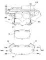
図5及び図6に示すように、ロワーローラユニット18は、ロワーブラケット18Aを介してスライドドア11に予め固定されている状態で、スライド装置20に組み付けられる。ロワーローラユニット18が組み付けられる際に、スライド装置20は、車体10のステップ部分に予め設置されている。なお、図5及び図6において、スライド装置20の動力ユニット20Aは省略されている。 As shown in FIGS. 5 and 6, the
ロワーレール14の左右のガイド壁14Aのうち車外側のガイド壁14Aには切欠挿入口38が形成されており、ロワーローラユニット18のガイドローラ27は、切欠挿入口38をから左右のガイド壁14Aの間に差し込まれる。ガイドローラ27が差し込まれた後、切欠挿入口38は別体のカバー39によって閉塞される。一方、ケーブルホルダ34は、ロワーレール14に沿った所定位置に配置されており、保持部材40によって所定位置に保持されている。保持部材40は、ケーブルホルダ34の保持を解除可能に構成されている。 Of the left and
ガイドローラ27が左右のガイド壁14Aの間に差し込まれたロワーローラユニット18は、ロワーレール14に沿って上記所定位置まで移動される。そして、上記所定位置において、ロワーローラユニット18のローラベース32とケーブルホルダ34のケーブルブラケット35Bとが一対の締結具37によって締結される。 The
ケーブルブラケット35Bは一対の被締結部41A,41Bを有し、一方の被締結部41Aは、ステップパネル21Bの下側に配置されており、他方の被締結部41Bは、ステップパネル21Bの車外側に突出して配置されている。ステップパネル21Bには、上記所定位置に保持されているケーブルホルダ34の被締結部41Aと重なる位置に開口部42が設けられており、一方の締結具37は、開口部42を通して被締結部41Aに挿通される。これにより、ケーブルホルダ34が保持されている所定位置においてロワーローラユニット18とケーブルホルダ34とを締結でき、組付作業に要する手間を軽減できる。 The
なお、保持部材40によるケーブルホルダ34の保持は、締結前又は締結後に解除される。解除可能な保持を提供する保持部材40は、帯状の部材であり、上記所定位置を通過してステップパネル21Bに環状に巻き付けられている。ケーブルホルダ34は、保持部材40によってステップパネル21Bに結束されることにより、ロワーレール14に沿った所定位置に保持されている。保持部材40としては、紐、ワイヤ、結束バンド等が用いられ、この種の保持部材40では、例えば保持部材40が切断されることによってケーブルホルダ34の保持が解除される。このように、ステップパネル21Bに環状に巻き付けられた保持部材40によってケーブルホルダ34を保持することにより、ケーブルホルダ34を上記所定位置に確実に保持できる。 The holding of the
好ましくは、保持部材40は、ロワーレール14を横断する方向に巻き付けられており、ケーブルホルダ34は、保持部材40をロワーレール14の延在方向に挟み込む係合部43を有する。図5及び図6に示す例では、係合部43は、ケーブル連結具35Aのケーブルヘッド24C及びケーブルヘッド24Dによって構成されているが、ケーブルヘッド24C及びケーブルヘッド24Dに限定されるものではない。ロワーレール14を横断する方向に巻き付けられた保持部材40を、係合部43によってロワーレール14の延在方向に挟み込むことにより、ケーブルホルダ34が保持部材40から脱落することを抑制でき、ケーブルホルダ34を上記所定位置に一層確実に保持できる。 Preferably, the holding
また、好ましくは、ステップパネル21Bは、保持部材40が嵌まり込む凹部44を、ロワーレール14に沿って延びる外縁部45に有し、保持部材40が挿通される貫通孔46を、ロワーレール14を挟んで外縁部45側とは反対側に有する。これにより、ステップパネル21Bに環状に巻き付けられた保持部材40のずれを抑制でき、ケーブルホルダ34を上記所定位置に一層確実に保持できる。なお、凹部44及び貫通孔46のうち、少なくとも一方が設けられていればよい。 Further, preferably, the
図7に示すように、動力ユニット20Aにおいて、モータ22のモータ軸22A、開扉ワイヤードラム23Aのドラム軸23C、及び閉扉ワイヤードラム23Bのドラム軸23Dの各軸芯は、互いに平行に設定されており、モータ22、開扉ワイヤードラム23A、及び閉扉ワイヤードラム23Bは、軸芯方向において互いに重合しないように配置されている。これにより、動力ユニット20Aの厚みが有意に抑制され得る。モータ22は、開扉ワイヤードラム23A及び閉扉ワイヤードラム23Bと同じ回転平面に配置されるのが望ましい。これにより、動力ユニット20Aの厚みがさらに抑制される。 As shown in FIG. 7, in the
モータ22のモータ軸22Aには、モータ歯車22Bが固定されている。モータ歯車22Bは好適にはヘリカルギヤである。モータ歯車22Bには、2段ギヤ30の大径ギヤ30Aが噛み合っており、2段ギヤ30のギヤ軸30Bは、モータ軸22A、ドラム軸23C、及びドラム軸23Dと平行に配置されている。2段ギヤ30の小径ギヤ30Cは、開扉ワイヤードラム23Aの外周ギヤ及び閉扉ワイヤードラム23Bの外周ギヤに噛み合っている。 A
モータ22の回転は、2段ギヤ30を介して開扉ワイヤードラム23A及び閉扉ワイヤードラム23Bに伝達され、開扉ワイヤードラム23A及び閉扉ワイヤードラム23Bは等速で同一方向に回転される。ワイヤーケーブルの巻き取り及び繰り出しを行うワイヤードラムが、開扉ワイヤードラム23Aと閉扉ワイヤードラム23Bとに分割されており、且つ開扉ワイヤードラム23Aと閉扉ワイヤードラム23Bとが、別軸により互いに重合しない位置に軸支されているので、単一のワイヤードラムに比べて、ワイヤードラムの軸方向の厚さが有意に短縮され得る。 Rotation of the
モータ22は、特に限定されるものではないが、例えばインナーロータ型のブラシレスモータが用いられる。ブラシレスモータは、ブラシを用いないため薄型であり、また、高寿命であり、さらに機械的効率も高くなる。ブラシレスモータは、通電時の摺接がないことから摺動音が生じずに静音性に優れ、ブラシによるスパークの発生がないためEMCノイズ問題も回避できる。また、インナーロータ型のブラシレスモータは、コイルを外周側に配置できるので放熱性に優れ、回転イナーシャを低減できる。ブラシレスモータは多極化が容易であり、多極化することによりコギングの低減を図れる。 Although the
モータ22がブラシレスモータであるものとして、モータ22は、ブラシレスの特性として停止状態においても保持トルクを発生させる停止保持制御を行うことができる。停止保持制御とは、別途クラッチなしでモータ22をプレーキとして使用するもので、このため、スライドドア11を停止状態で保持することができ、また、所定角度の傾斜地においてもスライドドア11を停止状態で保持することができる。クラッチのないモータ22は動力ユニット20Aの小型化、薄型化に貢献する。 Assuming that the
モータ22は、ステッピングモータのようなステップ制御を行うことができて制御性や回転精度に優れる。また、モータ22は正弦波駆動することも可能であり、トルク変動を低減させることができる。 The
モータ22の停止保持制御は、スライドドア11のスライド移動を急制動させることもできる。モータ22ではベクトル制御により永久磁石の磁力を変化させることができ、スライドドア11の種類やその他の仕様により、高トルク低回転運転や低トルク高回転運転を行うことができる。さらに、高電圧低回転制御によりステッピングモータのような動作が得られる。低電圧高回転制御では、スライドドア11の手動開閉モードにおいて人手による開閉操作のアシストをすることができる。 The stop holding control of the
モータ22にブラシレスモータを採用することにより、上記の特徴を生かしてスライドドア11の挙動を安定化できる。制御性の向上により低電流動作が可能となり、ハーネス径及びヒューズ容量を低減化し、コストダウンを図ることができる。 By adopting a brushless motor as the
このように、モータ22のモータ軸22A方向の小型化、ワイヤードラムを一対の開扉ワイヤードラム23Aと閉扉ワイヤードラム23Bとに分割することによるドラム軸23C,23D方向の小型化、モータ22、開扉ワイヤードラム23A、及び閉扉ワイヤードラム23Bを互いに軸方向に重合させない配置とすることによる軸方向の小型化に基づいて、動力ユニット20Aの厚さを有意に減少させることができる。これにより、車体パネル21Aと化粧パネル21Cとの間の上下方向の狭い空間内に、ステップパネル21B及び動力ユニット20Aを円滑に収納でき、ステップパネル21Bの上面及び化粧パネル21Cをより平坦にすることができる。 In this way, the size of the
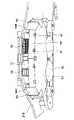
図8から図10に示すように、動力ユニット20Aは、第1収容体50と、第2収容体51と、防水カバー52とを有する。第1収容体50は、開扉ワイヤードラム23A(図7参照)及び閉扉ワイヤードラム23B(図7参照)をステップパネル21Bの下面との間に収容している。第2収容体51は、モータ22(図7参照)及びモータ22の回転を制御する制御装置53をステップパネル21Bの下面との間に収容している。なお、2段ギヤ30(図7参照)は、第1収容体50と、第2収容体51とに跨って収容されている。第2収容体51の車内側の後壁には切り欠き部が設けられており、切り欠き部にはモータ22や制御装置53に接続されているコネクタ54が配置されている。 As shown in FIGS. 8 to 10, the
モータ22、開扉ワイヤードラム23A、及び閉扉ワイヤードラム23Bは、軸芯方向において互いに重合しないように配置されており、モータ22は、開扉ワイヤードラム23A及び閉扉ワイヤードラム23Bの車内側に配置されている。したがって、モータ22及び制御装置53を収容している第2収容体51は、開扉ワイヤードラム23A及び閉扉ワイヤードラム23Bを収容している第1収容体50の車内側に隣設されている。 The
ステップパネル21Bの下面に沿って車内外方向と交差する前後方向において、第2収容体51の幅は第1収容体50の幅と略同じに形成されており、車外側から車内外方向にみた場合に、第2収容体51は第1収容体50の背後に隠れる。これに対し、第2収容体51を覆う防水カバー52は、前後方向に第1収容体50の外側に突出している一対の側壁55A,55Bを有し、側壁55A,55Bとステップパネル21Bとの間にはシール材56が設けられている。 The width of the second containing
側壁55Aは、車外側(スライドドア11側)に位置する前部側壁57Aと、車内側に位置する後部側壁58Aとを有し、側壁55Bもまた、前部側壁57Bと、後部側壁58Bとを有する。一対の前部側壁57A,57Bは、車内側に向けて互いに離間するように傾斜しており、一対の後部側壁58A,58Bは、車内側に向けて互いに接近するように傾斜している。シール材56は、前部側壁57A,57Bとステップパネル21Bの下面との間に介在している。なお、シール材56は、さらに後部側壁58A,58Bとステップパネル21Bの下面との間に介在してもよい。 The
後部側壁58A,58Bには、止水壁59が設けられおり、止水壁59は、ステップパネル21Bの下面に沿って車内外方向と交差する前後方向に、防水カバー52の外側に突出している。 A
車外側から車体パネル21Aと化粧パネル21Cとの間に進入する水は、第1収容体50の外側に突出している防水カバー52の側壁55A,55Bによって、防水カバー52の内部の第2収容体51から遠ざけられる。これにより、防水カバー52に収容されているモータ22や制御装置53の被水が抑制される。 Water entering between the
特に、側壁55A,55Bの車外側の前部側壁57A,57Bが、車内側に向けて互いに離間するように傾斜していることにより、車外側から車体パネル21Aと化粧パネル21Cとの間に進入する水を、効果的に第2収容体51から遠ざけることができる。そして、側壁55A,55Bの車内側の後部側壁58A,58Bが、前部側壁57A,57Bとは逆に車内側に向けて互いに接近するように傾斜していることにより、水が側壁55A,55Bを伝って防水カバー52の後壁60に到達することを抑制できる。 In particular,
好ましくは、後部側壁58A,58Bに止水壁59が設けられ、止水壁59により、水が側壁55A,55Bを伝って防水カバー52の後壁60に到達することを一層抑制できる。また、好ましくは、後壁60に一つ以上の排水孔61が形成される。これにより、万一、防水カバー52の内部に水が浸入したとしても、防水カバー52の内部に水が溜まることを防止でき、モータ22や制御装置53の被水を一層抑制できる。 Preferably, a
以上、説明したとおり、本明細書に開示されたスライド装置は、車体の乗降口のステップ部に設けられ、当該乗降口を閉じるスライドドアを開扉方向及び閉扉方向に移動させるスライド装置であって、前記ステップ部に配置されるステップパネルと、前記ステップパネルの下面に形成されており、前記スライドドアに固定されるローラユニットを開扉方向及び閉扉方向にガイドするレールと、前記ステップパネルの下面側に配置されており、前記レールに係合した前記ローラユニットと締結される被締結部を有するホルダと、前記ステップパネルに取り付けられており、前記ホルダを前記レールに沿って開扉方向及び前記閉扉方向に移動させる動力ユニットと、前記ホルダを前記レールに沿った所定位置に保持しており、前記ホルダの保持を解除可能な保持部材と、を備え、前記ステップパネルは、前記所定位置に保持されている前記ホルダの前記被締結部と重なる位置に、締結具を挿通可能な開口部を有する。 As described above, the slide device disclosed in the present specification is a slide device that is provided at a step portion of an entrance/exit of a vehicle body and moves a slide door that closes the entrance/exit in the opening direction and the closing direction. a step panel disposed on the step portion; a rail formed on the lower surface of the step panel for guiding the roller unit fixed to the sliding door in the door opening direction and the door closing direction; and the lower surface of the step panel. a holder having a fastened portion fastened to the roller unit engaged with the rail; and a holder attached to the step panel. a power unit for moving the door in a closing direction; and a holding member that holds the holder at a predetermined position along the rail and can release the holding of the holder, and the step panel is held at the predetermined position. An opening through which a fastener can be inserted is provided at a position overlapping the portion to be fastened of the holder.
また、本明細書に開示されたスライド装置は、前記保持部材が、帯状の部材であり、前記所定位置を通過して前記ステップパネルに環状に巻き付けられ、前記ホルダは、前記保持部材によって前記ステップパネルに結束される。 Further, in the slide device disclosed in this specification, the holding member is a strip-shaped member that passes through the predetermined position and is looped around the step panel, and the holder is attached to the step panel by the holding member. bound to the panel.
また、本明細書に開示されたスライド装置は、前記保持部材が、前記レールを横断する方向に巻き付けられており、前記ホルダは、前記保持部材を前記レールの延在方向に挟み込む係合部を有する。 Further, in the slide device disclosed in this specification, the holding member is wound in a direction transverse to the rail, and the holder has engaging portions that sandwich the holding member in the extending direction of the rail. have.
また、本明細書に開示されたスライド装置は、前記ステップパネルが、前記保持部材が嵌まり込む凹部を、前記レールに沿って延びる外縁部に有し、及び/又は、前記保持部材が挿通される貫通孔を、前記レールを挟んで前記外縁部側とは反対側に有する。 Further, in the slide device disclosed in this specification, the step panel has a recess in which the holding member is fitted in an outer edge portion extending along the rail, and/or a recess through which the holding member is inserted. and a through hole on the side opposite to the outer edge side with the rail interposed therebetween.
また、本明細書に開示されたスライド装置は、前記動力ユニットが、開扉ケーブルと、閉扉ケーブルと、前記開扉ケーブルの第1端部側を巻き取る開扉ドラムと、前記閉扉ケーブルの第1端部側を巻き取る閉扉ドラムと、前記開扉ドラム及び前記閉扉ドラムを回転させるモータと、を備え、前記開扉ケーブルの第2端部は、前記レールの開扉方向端部を回って前記ホルダに接続されており、前記閉扉ケーブルの第2端部は、前記レールの閉扉方向端部を回って前記ホルダに接続されている。 Further, in the slide device disclosed in this specification, the power unit includes a door opening cable, a door closing cable, a door opening drum for winding a first end side of the door opening cable, and a first end portion of the door closing cable. A door-opening drum for winding one end side, and a motor for rotating the door-opening drum and the door-closing drum, wherein the second end of the door-opening cable rotates around the end of the rail in the door-opening direction. The second end of the door closing cable is connected to the holder around the end of the rail in the door closing direction.
また、本明細書に開示されたスライド装置は、前記動力ユニットが、前記ステップパネルの下面側に配置されている。 Further, in the slide device disclosed in this specification, the power unit is arranged on the lower surface side of the step panel.
10 車体
11 スライドドア
12 乗降口
13 アッパーレール
14 ロワーレール
14A ガイド壁
15 センターレール
16 クオータパネル
17 アッパーローラユニット
18 ロワーローラユニット
18A ロワーブラケット
19 センタローラユニット
20 スライド装置
20A 動力ユニット
21 ステップ部分
21A 車体パネル
21B ステップパネル
21C 化粧パネル
22 モータ
22A モータ軸
22B モータ歯車
23A 開扉ワイヤードラム
23B 閉扉ワイヤードラム
23C ドラム軸
23D ドラム軸
24A 開扉ケーブル
24B 閉扉ケーブル
24C ケーブルヘッド
24D ケーブルヘッド
25A 後側反転プーリー
25B 前側反転プーリー
26 縦軸
27 ガイドローラ
28 横軸
29 転動ローラ
30A 大径ギヤ
30B ギヤ軸
30C 小径ギヤ
31 上面
31A 移動軌跡
32 ローラベース
32A 軸穴
32B 水平突部
33 軸
34 ホルダ
34 ケーブルホルダ
35A ケーブル連結具
35B ケーブルブラケット
36 リベット
37 締結具
38 切欠挿入口
39 カバー
40 保持部材
41A 被締結部
41B 被締結部
42 開口部
43 係合部
44 凹部
45 外縁部
46 貫通孔
50 第1収容体
51 第2収容体
52 防水カバー
53 制御装置
54 コネクタ
55A 側壁
55B 側壁
56 シール材
57A 前部側壁
57B 前部側壁
58A 後部側壁
58B 後部側壁
59 止水壁
60 後壁
61 排水孔10
Claims (6)
Translated fromJapanese前記ステップ部に配置されるステップパネルと、
前記ステップパネルの下面に形成されており、前記スライドドアに固定されるローラユニットを開扉方向及び閉扉方向にガイドするレールと、
前記ステップパネルの下面側に配置されており、前記レールに係合した前記ローラユニットと締結される被締結部を有するホルダと、
前記ステップパネルに取り付けられており、前記ホルダを前記レールに沿って開扉方向及び前記閉扉方向に移動させる動力ユニットと、
前記ホルダを前記レールに沿った所定位置に保持しており、前記ホルダの保持を解除可能な保持部材と、
を備え、
前記ステップパネルは、前記保持部材によって前記所定位置に保持されている状態の前記ホルダの前記被締結部と重なる位置に、締結具を挿通可能な開口部を有し、
前記締結具が前記開口部を通して前記被締結部に挿通されて前記所定位置において前記ローラユニットと前記ホルダとが締結され、前記ローラユニットと前記ホルダとが締結された後に、前記保持部材による前記ホルダの保持が解除されるスライド装置。A slide device provided at a step portion of an entrance of a vehicle body for moving a slide door closing the entrance/exit in a door opening direction and a door closing direction,
a step panel arranged on the step portion;
a rail that is formed on the lower surface of the step panel and guides a roller unit fixed to the sliding door in a door opening direction and a door closing direction;
a holder disposed on the lower surface side of the step panel and having a fastened portion to be fastened with the roller unit engaged with the rail;
a power unit attached to the step panel for moving the holder along the rail in the door opening direction and the door closing direction;
a holding member that holds the holder at a predetermined position along the rail and can release the holding of the holder;
with
The step panel has an opening through which a fastener can be inserted, at a position overlapping the fastened portionof the holder held at the predetermined positionby the holding member,
The fastener is inserted into the fastened portion through the opening, the roller unit and the holder are fastened at the predetermined position, and after the roller unit and the holder are fastened, the holder is held by the holding member. A sliding device in which the holding of the is released .
前記保持部材は、帯状の部材であり、前記所定位置を通過して前記ステップパネルに環状に巻き付けられ、
前記ホルダは、前記保持部材によって前記ステップパネルに結束されるスライド装置。The slide device according to claim 1,
The holding member is a strip-shaped member, passes through the predetermined position, and is looped around the step panel,
The holder is a slide device bound to the step panel by the holding member.
前記保持部材は、前記レールを横断する方向に巻き付けられており、
前記ホルダは、前記保持部材を前記レールの延在方向に挟み込む係合部を有するスライド装置。The slide device according to claim 2,
The holding member is wound in a direction transverse to the rail,
The slide device, wherein the holder has an engaging portion that sandwiches the holding member in the extending direction of the rail.
前記ステップパネルは、
前記保持部材が嵌まり込む凹部を、前記レールに沿って延びる外縁部に有し、
及び/又は、
前記保持部材が挿通される貫通孔を、前記レールを挟んで前記外縁部側とは反対側に有するスライド装置。A slide device according to claim 3,
The step panel is
An outer edge portion extending along the rail has a recess into which the holding member is fitted,
and/or
A slide device having a through hole through which the holding member is inserted, on the side opposite to the outer edge side with the rail interposed therebetween.
前記動力ユニットは、
開扉ケーブルと、
閉扉ケーブルと、
前記開扉ケーブルの第1端部側を巻き取る開扉ドラムと、
前記閉扉ケーブルの第1端部側を巻き取る閉扉ドラムと、
前記開扉ドラム及び前記閉扉ドラムを回転させるモータと、
を備え、
前記開扉ケーブルの第2端部は、前記レールの開扉方向端部を回って前記ホルダに接続されており、
前記閉扉ケーブルの第2端部は、前記レールの閉扉方向端部を回って前記ホルダに接続されているスライド装置。The slide device according to any one of claims 1 to 4,
The power unit is
a door opening cable;
a closing cable;
a door-opening drum for winding the first end side of the door-opening cable;
a door-closing drum for winding the first end side of the door-closing cable;
a motor that rotates the door opening drum and the door closing drum;
with
a second end of the door-opening cable is connected to the holder around an end of the rail in the door-opening direction;
A sliding device in which a second end of the door-closing cable is connected to the holder around an end of the rail in the door-closing direction.
前記動力ユニットは、前記ステップパネルの下面側に配置されているスライド装置。A sliding device according to claim 5,
The power unit is a slide device arranged on the lower surface side of the step panel.
Priority Applications (2)
| Application Number | Priority Date | Filing Date | Title |
|---|---|---|---|
| JP2019174286AJP7210855B2 (en) | 2019-09-25 | 2019-09-25 | slide device |
| CN202022070713.9UCN213619288U (en) | 2019-09-25 | 2020-09-21 | Sliding device |
Applications Claiming Priority (1)
| Application Number | Priority Date | Filing Date | Title |
|---|---|---|---|
| JP2019174286AJP7210855B2 (en) | 2019-09-25 | 2019-09-25 | slide device |
Publications (2)
| Publication Number | Publication Date |
|---|---|
| JP2021049877A JP2021049877A (en) | 2021-04-01 |
| JP7210855B2true JP7210855B2 (en) | 2023-01-24 |
Family
ID=75156813
Family Applications (1)
| Application Number | Title | Priority Date | Filing Date |
|---|---|---|---|
| JP2019174286AActiveJP7210855B2 (en) | 2019-09-25 | 2019-09-25 | slide device |
Country Status (2)
| Country | Link |
|---|---|
| JP (1) | JP7210855B2 (en) |
| CN (1) | CN213619288U (en) |
Families Citing this family (1)
| Publication number | Priority date | Publication date | Assignee | Title |
|---|---|---|---|---|
| CN113276642B (en)* | 2021-06-29 | 2022-07-22 | 东风柳州汽车有限公司 | Inhaul cable installation structure, automobile and installation method of automobile sliding door inhaul cable |
Citations (5)
| Publication number | Priority date | Publication date | Assignee | Title |
|---|---|---|---|---|
| JP2003227965A (en) | 2002-02-05 | 2003-08-15 | Auto Network Gijutsu Kenkyusho:Kk | Optical connector and optical fiber cord fixing part structure |
| JP2014199069A (en) | 2013-03-29 | 2014-10-23 | 住友電装株式会社 | Wiring unit for automatic transmission |
| JP2015123792A (en) | 2013-12-25 | 2015-07-06 | アイシン精機株式会社 | Door opening and closing device |
| JP2015171743A (en) | 2014-03-12 | 2015-10-01 | 株式会社マキタ | tool storage case |
| JP2018076024A (en) | 2016-11-11 | 2018-05-17 | 日野自動車株式会社 | Hybrid truck and construction method for installing PCU in hybrid truck |
- 2019
- 2019-09-25JPJP2019174286Apatent/JP7210855B2/enactiveActive
- 2020
- 2020-09-21CNCN202022070713.9Upatent/CN213619288U/enactiveActive
Patent Citations (5)
| Publication number | Priority date | Publication date | Assignee | Title |
|---|---|---|---|---|
| JP2003227965A (en) | 2002-02-05 | 2003-08-15 | Auto Network Gijutsu Kenkyusho:Kk | Optical connector and optical fiber cord fixing part structure |
| JP2014199069A (en) | 2013-03-29 | 2014-10-23 | 住友電装株式会社 | Wiring unit for automatic transmission |
| JP2015123792A (en) | 2013-12-25 | 2015-07-06 | アイシン精機株式会社 | Door opening and closing device |
| JP2015171743A (en) | 2014-03-12 | 2015-10-01 | 株式会社マキタ | tool storage case |
| JP2018076024A (en) | 2016-11-11 | 2018-05-17 | 日野自動車株式会社 | Hybrid truck and construction method for installing PCU in hybrid truck |
Also Published As
| Publication number | Publication date |
|---|---|
| CN213619288U (en) | 2021-07-06 |
| JP2021049877A (en) | 2021-04-01 |
Similar Documents
| Publication | Publication Date | Title |
|---|---|---|
| US7770961B2 (en) | Compact cable drive power sliding door mechanism | |
| US7866732B2 (en) | Compact cable drive power sliding door mechanism | |
| US8857104B2 (en) | Vehicle door opening device | |
| JP5125234B2 (en) | Sliding door device for vehicle | |
| JP5796238B2 (en) | Opening and closing device for vehicle door | |
| US7854093B2 (en) | Automatic opening/closing apparatus for vehicle | |
| EP1953324B1 (en) | Automatic opening/closing apparatus for vehicle | |
| JP7210855B2 (en) | slide device | |
| JP5578067B2 (en) | SLIDE DOOR OPENING / CLOSING DEVICE AND METHOD OF INSTALLING THE SAME | |
| US20060042168A1 (en) | Vehicle door opening and closing device | |
| JP2007223402A (en) | Sliding door opening and closing device | |
| JP4746400B2 (en) | Wire winding device | |
| JP7081750B2 (en) | Slide device | |
| JP7294597B2 (en) | slide device | |
| JP6854309B2 (en) | Power slide device for vehicle slide door | |
| JP2012131457A (en) | Device for opening and closing slide door | |
| JP4960111B2 (en) | Automatic switchgear for vehicles | |
| JP2006132255A (en) | Vehicle sliding door opening and closing device | |
| JP4769140B2 (en) | Automatic door device | |
| JPH11245666A (en) | Slide door opening and closing device for automobile | |
| JP6854310B2 (en) | Power slide device for vehicle slide door | |
| JP2020197093A (en) | Power sliding device of vehicle sliding door | |
| JP5589332B2 (en) | Vehicle door opening and closing device | |
| JP2020148083A (en) | Power slide device of vehicle slide door | |
| JP2012219592A (en) | Driving device of opening/closing body for vehicle |
Legal Events
| Date | Code | Title | Description |
|---|---|---|---|
| A625 | Written request for application examination (by other person) | Free format text:JAPANESE INTERMEDIATE CODE: A625 Effective date:20210709 | |
| A977 | Report on retrieval | Free format text:JAPANESE INTERMEDIATE CODE: A971007 Effective date:20220616 | |
| A131 | Notification of reasons for refusal | Free format text:JAPANESE INTERMEDIATE CODE: A131 Effective date:20220621 | |
| A521 | Request for written amendment filed | Free format text:JAPANESE INTERMEDIATE CODE: A523 Effective date:20220817 | |
| TRDD | Decision of grant or rejection written | ||
| A01 | Written decision to grant a patent or to grant a registration (utility model) | Free format text:JAPANESE INTERMEDIATE CODE: A01 Effective date:20221213 | |
| A61 | First payment of annual fees (during grant procedure) | Free format text:JAPANESE INTERMEDIATE CODE: A61 Effective date:20221221 | |
| R150 | Certificate of patent or registration of utility model | Ref document number:7210855 Country of ref document:JP Free format text:JAPANESE INTERMEDIATE CODE: R150 |