JP7207916B2 - In-vehicle device - Google Patents
In-vehicle deviceDownload PDFInfo
- Publication number
- JP7207916B2 JP7207916B2JP2018172511AJP2018172511AJP7207916B2JP 7207916 B2JP7207916 B2JP 7207916B2JP 2018172511 AJP2018172511 AJP 2018172511AJP 2018172511 AJP2018172511 AJP 2018172511AJP 7207916 B2JP7207916 B2JP 7207916B2
- Authority
- JP
- Japan
- Prior art keywords
- vehicle
- event
- inter
- distance
- stopped
- Prior art date
- Legal status (The legal status is an assumption and is not a legal conclusion. Google has not performed a legal analysis and makes no representation as to the accuracy of the status listed.)
- Active
Links
- 238000001514detection methodMethods0.000claimsdescription20
- 230000007423decreaseEffects0.000claimsdescription7
- 230000007704transitionEffects0.000claimsdescription6
- 238000011156evaluationMethods0.000description23
- 238000012545processingMethods0.000description22
- 230000006870functionEffects0.000description19
- 238000004891communicationMethods0.000description14
- 238000000034methodMethods0.000description14
- 238000004458analytical methodMethods0.000description9
- 230000001133accelerationEffects0.000description8
- 238000003909pattern recognitionMethods0.000description8
- 238000004364calculation methodMethods0.000description4
- 239000000446fuelSubstances0.000description2
- 238000010295mobile communicationMethods0.000description2
- 230000005540biological transmissionEffects0.000description1
- 238000004422calculation algorithmMethods0.000description1
- 230000001413cellular effectEffects0.000description1
- 230000000295complement effectEffects0.000description1
- 239000000498cooling waterSubstances0.000description1
- 238000007405data analysisMethods0.000description1
- 230000001934delayEffects0.000description1
- 238000010586diagramMethods0.000description1
- 239000006185dispersionSubstances0.000description1
- 238000006073displacement reactionMethods0.000description1
- 239000000284extractSubstances0.000description1
- 230000008571general functionEffects0.000description1
- 238000003384imaging methodMethods0.000description1
- 239000004973liquid crystal related substanceSubstances0.000description1
- 230000007774longtermEffects0.000description1
- 238000000691measurement methodMethods0.000description1
- 229910044991metal oxideInorganic materials0.000description1
- 150000004706metal oxidesChemical class0.000description1
- 239000004065semiconductorSubstances0.000description1
Images


Landscapes
- Time Recorders, Dirve Recorders, Access Control (AREA)
- Traffic Control Systems (AREA)
Description
Translated fromJapanese本発明は、運転の評価に利用可能な情報を生成する車載器に関する。 TECHNICAL FIELD The present invention relates to a vehicle-mounted device that generates information that can be used for driving evaluation.
例えばトラックなどの業務用車両は、乗務員の労務管理や安全運転管理などに利用可能な運行データを自動的に記録するための車載器として、デジタルタコグラフやドライブレコーダを搭載している場合が多い。また、このような車載器は、近年では乗務員の危険運転を評価するための機能を有する場合もある。 For example, commercial vehicles such as trucks are often equipped with digital tachographs and drive recorders as in-vehicle devices for automatically recording operational data that can be used for crew management and safe driving management. Moreover, in recent years, such an on-vehicle device may have a function for evaluating dangerous driving by a crew member.
例えば、特許文献1に記載の車両用運行記録評価装置は、運転者以外の管理者等が各運転者の走行中における危険運転状態を客観的にかつ容易に把握でき、運転評価の際の労力が低減される技術を示している。具体的には、運転中に運転状況情報が時系列にデジタルタコグラフにより保存されると共に、この運転状況情報に基づいて運転状態評価部により危険運転状態と判定されるときにトリガー信号が出力される。そして、このトリガー信号に基づいてデジタルタコグラフにより、危険運転状態が発生じた時点の運転状況情報に印(フラグ)が付されて記録される。また、段落「0053」において、車間距離状況に基づき危険運転状態を検出する具体例として、車速/車間距離の平均値が閾値以上かどうかを判断することを示している。 For example, the vehicle operation record evaluation device described in
また、特許文献2に記載の運転状況推定装置は、ドライバに応じた運転支援をより的確に行うための技術を示している。具体的には、運転環境を推定し、目標値設定部では、その運転環境毎に用意された推定モデルを用いて、現在の運転環境やドライバ,天気,時間帯に適した車間距離及び衝突余裕時間の目標値を設定し、運転状況推定部は、その目標値に対する実際の検出値の逸脱度を、ドライバの運転状況を示す推定値として出力する。 Further, the driving situation estimation device described in Patent Document 2 shows a technique for more accurately performing driving assistance according to the driver. Specifically, the driving environment is estimated, and the target value setting section uses an estimation model prepared for each driving environment to determine the following distance and collision margin suitable for the current driving environment, driver, weather, and time of day. A target value of time is set, and the driving condition estimation unit outputs the degree of deviation of the actual detected value from the target value as an estimated value indicating the driving condition of the driver.
また、特許文献3は、車間距離に対する運転評価を実現するための技術を開示している。具体的には、記憶部と選択部と取得部と判断部とを有する。記憶部は、車両の速度と、サイズの異なるテンプレートとを対応づけたデータテーブルを記憶する。選択部は、記憶部に記憶されたデータテーブルに基づき、運転中の車両の速度に対応したサイズのテンプレートを選択する。取得部は、運転中の車両の前方を走行中の車両のナンバープレートの画像を取得する。判断部は、選択部により選択されたテンプレートと、取得部により取得されたナンバープレートの画像とに基づき、運転中の車両と、運転中の車両の前方を走行中の車両との車間距離の適否を判断する。 Further, Patent Literature 3 discloses a technique for realizing driving evaluation with respect to inter-vehicle distance. Specifically, it has a storage unit, a selection unit, an acquisition unit, and a determination unit. The storage unit stores a data table that associates vehicle speeds with templates of different sizes. The selection unit selects a template having a size corresponding to the speed of the vehicle being driven based on the data table stored in the storage unit. The acquisition unit acquires an image of a license plate of a vehicle running in front of the vehicle being driven. The judging unit judges whether the inter-vehicle distance between the vehicle being driven and the vehicle running in front of the vehicle being driven is appropriate based on the template selected by the selecting unit and the license plate image acquired by the acquiring unit. to judge.
デジタルタコグラフなどの車載器において、運転評価の対象車両とその前方の他車両との間の車間距離を評価する場合には、特許文献2に示されているように車間距離及び衝突余裕時間が重要になる。 In vehicle-mounted devices such as digital tachographs, when evaluating the inter-vehicle distance between the target vehicle for driving evaluation and another vehicle in front of it, the inter-vehicle distance and collision margin time are important as shown in Patent Document 2. become.
つまり、車両が高速で走行している場合には、衝突までの余裕時間が小さいので、車載器は、十分に大きい車間距離を確保していない場合は危険性が高いと評価できる。一方、車両が低速で走行している場合には、衝突までの余裕時間が十分大きいので、車間距離の大きさはあまり重要ではない。したがって、例えば特許文献1の段落「0053」に示されているように、車載器は、車速/車間距離の平均値を閾値と比較して評価することになる。 In other words, when the vehicle is traveling at high speed, the margin of time until collision is short, so the vehicle-mounted device can be evaluated as having a high risk unless a sufficiently large inter-vehicle distance is secured. On the other hand, when the vehicle is traveling at a low speed, the time to collision is sufficiently long, so the size of the inter-vehicle distance is not so important. Therefore, for example, as described in paragraph "0053" of
そのため、従来の評価方法では、赤信号の交差点において低速で走行しながら停止するような場合には、対象車両と前方の他車両との車間距離が異常に小さくなったとしても問題なしと評価される可能性が高い。 Therefore, in the conventional evaluation method, in the case of stopping while traveling at a low speed at an intersection with a red light, even if the inter-vehicle distance between the subject vehicle and the other vehicle ahead becomes abnormally small, it is evaluated as no problem. likely to
しかしながら、例えば煽り運転のような状況においては、対象車両の運転者は、赤信号の交差点で故意に前方車両との車間距離を詰めて車両を停止させる可能性がある。 However, for example, in situations such as leaning, the driver of the target vehicle may intentionally close the distance to the preceding vehicle at an intersection with a red light and stop the vehicle.
また、例えばトラックやバスを運転する場合には、運転者の目線の位置は、一般の乗用車と比較して高く、しかも車体のボンネットのように前方に張り出している部位がほとんどない場合が多いので、交差点などで停車する場合に、運転者は、故意でないにもかかわらず、一般の乗用車と比べて前方車両との車間距離を詰めた状態で停車する傾向がある。 Also, when driving a truck or bus, for example, the position of the driver's line of sight is higher than that of an ordinary passenger car, and in many cases, there is almost no part that protrudes forward like the hood of the vehicle body. When stopping at an intersection or the like, the driver tends to stop the vehicle in a state where the distance between the vehicle and the preceding vehicle is shortened compared to a general passenger vehicle, although it is not intentional.
また、赤信号の交差点などにおいて、例えば普通乗用車の後方に、大型のトラックやバスが車間距離を詰めて停車したような場合には、前方の車両の運転者は、後方の車両の存在により圧迫感や恐怖感を覚える場合がある。そして、後方の車両の運転者が故意に車間距離を詰めたのではないにもかかわらず、前方の車両の運転者は、後方車両の運転者マナーが悪いと感じてしまう。更に、後方の車両を管理している運送会社やバス会社に対して、マナーの悪い運転に関する身に覚えのない苦情が届く可能性がある。 Also, at an intersection with a red light, for example, when a large truck or bus stops behind a passenger car with a close distance between them, the driver of the vehicle in front is put under pressure by the presence of the vehicle behind. You may feel a sense of dread and fear. Then, even though the driver of the vehicle behind does not intentionally reduce the inter-vehicle distance, the driver of the vehicle ahead feels that the manner of the driver of the vehicle behind is bad. Furthermore, there is a possibility that unfamiliar complaints about bad manners will reach the transport company or bus company that manages the vehicles behind.
したがって、大型のトラックやバスなどを運転する場合には、運転者は、赤信号の交差点などにおいて、低速の状態から停止するような状況であっても、運転者の感覚のみに頼らず、十分な車間距離を確保して停止することが重要である。 Therefore, when driving a large truck or bus, the driver should not rely solely on the driver's senses, and should be able to stop at a low speed at an intersection with a red light. It is important to secure a sufficient inter-vehicle distance before stopping.
本発明は、上述した事情に鑑みてなされたものであり、その目的は、評価対象の車両が停止したときの車間距離を含む運転操作の傾向を適切に評価するために役立つ車載器を提供することにある。 SUMMARY OF THE INVENTION The present invention has been made in view of the circumstances described above, and its object is to provide an on-vehicle device that is useful for appropriately evaluating trends in driving operations, including the inter-vehicle distance when a vehicle to be evaluated has stopped. That's what it is.
前述した目的を達成するために、本発明に係る車載器は、下記(1)~(5)を特徴としている。
(1) 車両に搭載され、前記車両の運行時の状態を監視する車載器であって、
前記車両と、前記車両の前方の他車両との車間距離を計測する車間距離計測部と、
前記車両が走行状態から停車状態に遷移するときに発生した状況を停車時イベントとして検知するイベント検知部と、
前記停車時イベントで、少なくとも停車時の車間距離を出力に反映するイベント出力部と、
を備え、
前記イベント検知部は、前記車間距離の変化及び前記車両の車速の変化を監視し、前記車間距離が減少し且つ前記車速が減少する状態の継続中に前記車両が走行状態から停車状態に遷移する場合にのみ、その場合に発生した状況を前記停車時イベントとして検知する、
ことを特徴とする車載器。In order to achieve the above object, a vehicle-mounted device according to the present invention is characterized by the following (1) to (5).
(1) An on-vehicle device that is mounted on a vehicle and monitors the state of the vehicle during operation,
an inter-vehicle distance measuring unit that measures an inter-vehicle distance between the vehicle and another vehicle in front of the vehicle;
an event detection unit that detects a situation that occurs when the vehicle transitions from a running state to a stopped state as a stop event;
an event output unit that reflects at least the inter-vehicle distance when the vehicle is stopped in the output at the event when the vehicle is stopped;
with
The event detection unit monitors a change in the inter-vehicle distance and a change in the vehicle speed of the vehicle, and the vehicle transitions from a running state to a stop state while the inter-vehicle distance decreases and the vehicle speed decreases. Only when the vehicle is stopped, the situation that occurred in that case is detected as the event when the vehicle is stopped;
An in-vehicle device characterized by:
(2) 前記イベント出力部は、停車時の車間距離が閾値以下の場合に、前記車両の運転者に対して警報を通知する、
ことを特徴とする上記(1)に記載の車載器。(2) The event output unit notifies the driver of the vehicle of an alarm when the inter-vehicle distance when the vehicle is stopped is equal to or less than a threshold.
The vehicle-mounted device according to the above (1), characterized by:
(3) 前記イベント検知部は、前記車両が停車状態に遷移した時点から一定時間前の時刻の範囲について、減速度の統計量として平均値および分散値の少なくとも一方を算出する、
ことを特徴とする上記(1)に記載の車載器。(3) The event detection unit calculates at least one of an average value and a variance value as a statistic of deceleration for a range of times before a certain period of time from when the vehicle transitioned to a stopped state.
The vehicle-mounted device according to the above (1), characterized by:
(4) 前記イベント出力部は、前記イベント検知部が検知した停車時イベントに関連する情報を、自車両上で、又は遠隔地のサーバもしくは端末により記録する、
ことを特徴とする上記(1)乃至(3)のいずれかに記載の車載器。(4) The event output unit records information related to the stopping event detected by the event detection unit on the own vehicle or by a remote server or terminal.
The vehicle-mounted device according to any one of the above (1) to (3), characterized by:
(5) 前記停車時イベントの情報は、時刻、位置、停車時点近傍の減速度の統計量、および車間距離を含む、
ことを特徴とする上記(4)に記載の車載器。(5) The information of the stop event includes time, position, statistics of deceleration near the stop time, and inter-vehicle distance,
The vehicle-mounted device according to the above (4), characterized by:
上記(1)の構成の車載器によれば、停車時イベントの運転操作の傾向を正しく評価するためのデータを得ることができる。すなわち、トラックやバスなどが停止するときの運転操作について、前の車両との車間距離を必要以上に詰めた状態かどうかを評価することが容易になる。 According to the vehicle-mounted device having the configuration (1) above, it is possible to obtain data for correctly evaluating the tendency of the driving operation in the stop event. In other words, it becomes easy to evaluate whether or not the vehicle-to-vehicle distance to the preceding vehicle is narrowed more than necessary for the driving operation when the truck, bus, or the like stops.
上記(2)の構成の車載器によれば、トラックやバスなどが停止するときの運転操作について、前の車両との車間距離を必要以上に詰めた状態の場合に警報を出力し、十分な車間距離を確保するようにリアルタイムで運転者を指導することが可能になる。 According to the vehicle-mounted device having the above configuration (2), when the vehicle-to-vehicle distance between the vehicle and the preceding vehicle is narrowed more than necessary, the vehicle-mounted device outputs an alarm when the truck or bus stops. It becomes possible to guide the driver in real time so as to secure the following distance.
上記(3)の構成の車載器によれば、赤信号の交差点などで車両が停止するときの減速操作の運転傾向を正しく評価するために必要なデータが得られる。しかも、減速度の統計量を出力するので、車速の瞬時値データを細かく記録する必要がなく、記録するデータの容量を削減できる。更に、記録したデータを解析する際のデータ処理が容易になる。 According to the vehicle-mounted device having the above configuration (3), data necessary for correctly evaluating the driving tendency of the deceleration operation when the vehicle stops at an intersection with a red light can be obtained. Moreover, since the deceleration statistic is output, there is no need to record the instantaneous value data of the vehicle speed in detail, and the volume of data to be recorded can be reduced. Furthermore, data processing becomes easier when analyzing the recorded data.
上記(4)の構成の車載器によれば、前記停車時イベントに関連する情報を記録するので、記録した情報を車両の運行が終了した後で必要に応じて分析し、運転者毎の運転操作の傾向を把握することが可能になる。 According to the vehicle-mounted device having the above configuration (4), since the information related to the event at the time of stopping the vehicle is recorded, the recorded information is analyzed as necessary after the operation of the vehicle is completed, and the driving information for each driver is analyzed. It becomes possible to grasp the tendency of operation.
上記(5)の構成の車載器によれば、停車時イベントに関連する運転者毎の運転操作の傾向を正しく分析するために必要なデータが得られる。すなわち、時刻の違い、場所の違いに応じた運転操作の傾向や、停車前の減速操作の傾向、停車時の車間距離の傾向を把握できる。 According to the vehicle-mounted device having the configuration (5) above, data necessary for correctly analyzing the tendency of each driver's driving operation related to the stop event can be obtained. That is, it is possible to grasp the tendency of driving operation according to the difference in time and the difference in location, the tendency of deceleration operation before stopping, and the tendency of inter-vehicle distance when the vehicle is stopped.
本発明の車載器によれば、評価対象の車両が停止したときの車間距離などの運転操作の傾向を適切に評価するために役立つ停車時イベントの情報が得られる。 According to the vehicle-mounted device of the present invention, it is possible to obtain event information useful for appropriately evaluating driving operation tendencies such as inter-vehicle distance when the vehicle to be evaluated has stopped.
以上、本発明について簡潔に説明した。更に、以下に説明される発明を実施するための形態(以下、「実施形態」という。)を添付の図面を参照して通読することにより、本発明の詳細は更に明確化されるであろう。 The present invention has been briefly described above. Furthermore, the details of the present invention will be further clarified by reading the following detailed description of the invention (hereinafter referred to as "embodiment") with reference to the accompanying drawings. .
本発明に関する具体的な実施形態について、各図を参照しながら以下に説明する。
<運行評価システムの構成および動作の概要>
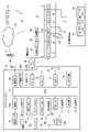
本発明の実施形態における車載器を含む運転評価システムの構成例を図1に示す。Specific embodiments relating to the present invention will be described below with reference to each drawing.
<Outline of operation evaluation system configuration and operation>
FIG. 1 shows a configuration example of a driving evaluation system including a vehicle-mounted device according to an embodiment of the present invention.
図1に示した運転評価システム5は、例えばトラックを管理している運送会社やバス会社等の事業者の設備として導入される。この運転評価システム5は、トラックやバス等の各車両における運転者の運転状況を評価する機能を備え、各車両に車載器として搭載された運行記録装置(以下、デジタルタコグラフという)10と、各事業者の事務所等に設置される事務所PC30とで構成されている。デジタルタコグラフ10と、事務所PC30との間は、インターネット70を介して通信できるように接続される。 The driving evaluation system 5 shown in FIG. 1 is introduced as equipment of an operator such as a transportation company or a bus company that manages trucks, for example. This driving evaluation system 5 has a function of evaluating the driving situation of a driver in each vehicle such as a truck or a bus, and includes a driving recorder (hereinafter referred to as a digital tachograph) 10 mounted as an on-vehicle device in each vehicle, and each It is configured with an
また、インターネット70に接続されているデータセンタ75のサービスを利用することも可能である。すなわち、各車両に搭載されたデジタルタコグラフ10が無線通信により送信するデータをインターネット70上のデータセンタ75のサーバで中継して事務所PC30に送信することができる。その場合、データセンタ75のサーバは、デジタルタコグラフ10や事務所PC30の代わりに様々なデータ処理を行ったり、運転評価を行ったり、該当するデジタルタコグラフ10や事務所PC30に対して警報を出力するようなサービスを実施することもできる。 It is also possible to use services of a
事務所PC30は、事務所に設置された汎用のコンピュータ装置で構成され、車両の運行状況や運転状況を管理する。インターネット70は、デジタルタコグラフ10と広域通信を行う無線基地局8や事務所PC30が接続されるパケット通信網であり、デジタルタコグラフ10と事務所PC30と間で行われるデータ通信を中継する。デジタルタコグラフ10と無線基地局8との間の通信は、LTE(Long Term Evolution)/4G(4th Generation)等のモバイル通信網(携帯回線網)で行われてもよいし、無線LAN(Local Area Network)で行われてもよい。 The
デジタルタコグラフ10は、各車両に搭載され、一般的な機能として、出入庫時刻、走行距離、走行時間、走行速度、速度オーバー、エンジン回転数オーバー、急発進、急加速、急減速等の運行データを記録する。 The
また、本実施形態のデジタルタコグラフ10は、上記の機能以外に、ドライブレコーダの機能および運転評価機能も搭載することができる。特徴的な機能としては、自車両が赤信号の交差点などで停車するような場合に、その前方を走行または停止している他車両、すなわち前方車両との間の車間距離を測定する。また、停車時の車間距離や停車する直前における減速状況の統計量も算出する。そして、このような停車時イベントにおける運転の傾向をリアルタイムで自動的に評価し、必要に応じて運転者に警報を報知したり、停車時イベントの運行データを記録する。 In addition to the functions described above, the
ここで、デジタルタコグラフ10が警報を出力する状況は、自車両の運転者が意図的なあおり運転により停車時に車間距離を詰めている状況や、運転者の無意識のうちに、単なる運転傾向として車間距離が詰まった状況が想定される。特に、トラックやバスのような車両の場合には、運転者の目線の位置が高く、しかもボンネットのように前方に張り出している領域が小さいので、後者の状況が発生しやすい。また、後者の状況では、自車両の運転者が故意に車間距離を詰めていないにもかかわらず、他車両の運転者等から運転のマナーが悪いと評価される可能性が高い。したがって、トラックやバスのような比較的大型の車両の場合には、自車両の運転者が意識的に十分な車間距離を確保するように、運転者に対して運転の指導を行うことが望まれる。 Here, the situation in which the
なお、上記のような運転評価の機能は、事務所PC30側に搭載することもできる。事務所PC30は、各車両に搭載されたデジタルタコグラフ10が記録した運行データを車両の運行後に解析することにより、必要に応じて前記停車時イベントに関する運転評価を行い、各乗務員の安全運転の教育や指導に役立てることができる。また、データセンタ75を利用する場合には、データセンタ75におけるデータ処理サービスにおいて、前記停車時イベントに関する運転評価を行うことができる。 It should be noted that the function of driving evaluation as described above can also be installed on the
図1に示したデジタルタコグラフ10は、ハードウェアとして、CPU(マイクロコンピュータ)11、速度I/F(インタフェース)12A、エンジン回転I/F12B、外部入力I/F13、センサ入力I/F14、GPS受信部15、カメラI/F16、不揮発メモリ26A、揮発メモリ26B、記録部17、カードI/F18、音声I/F19、RTC(時計IC)21、SW入力部22、通信部24、表示部27、およびアナログ入力I/F29を内蔵している。 The
CPU11は、予め組み込まれたプログラムに従い、デジタルタコグラフ10の各部を統括的に制御する。不揮発メモリ26Aは、CPU11によって実行される動作プログラムや、CPU11が参照する定数データやテーブルなどを予め保持している。不揮発メモリ26Aは、データの書き換えが可能なメモリであり、保持しているデータは必要に応じて更新できる。 The
記録部17は、運行データや映像等のデータを記録する。カードI/F18には、乗務員が所持するメモリカード65が挿抜自在に接続される。CPU11は、カードI/F18に接続されたメモリカード65に対し運行データ、映像等のデータを書き込む。音声I/F19には、内蔵のスピーカ20が接続される。スピーカ20は、警報等の音声を発する。 The
RTC21(計時部)は、現在時刻を計時する。SW入力部22には、出庫ボタン、入庫ボタン等の各種ボタンのON/OFF信号が入力される。表示部27は、LCD(liquid crystal display)で構成され、通信や動作の状態の他、警報等を表示する。 The RTC 21 (timekeeping unit) measures the current time. The
速度I/F12Aには、車両の速度を検出する車速センサ51が接続され、車速センサ51からの速度パルスが入力される。車速センサ51は、デジタルタコグラフ10にオプションとして設けられてもよいし、デジタルタコグラフ10とは別の装置として設けられてもよい。エンジン回転I/F12Bには、エンジン回転数センサ(図示せず)からの回転パルスが入力される。 A
外部入力I/F13の入力には、自車両のブレーキのオンオフを表すブレーキ信号、左右の方向指示器(ウインカー)の動作状態を表すウインカー信号、自動変速機の変速状態(前進/後退の区別を含む)を表す変速信号等が外部機器(図示せず)から印加される。 Inputs to the external input I/
センサ入力I/F14には、加速度(G値)を検知する(衝撃を感知する)加速度センサ(Gセンサ)28が接続され、Gセンサ28からの信号が入力される。Gセンサとしては、加速度による機械的な変位を、振動として読み取る方式や光学的に読み取る方式を有するものが挙げられるが、特に限定されない。また、Gセンサは、車両前方からの衝撃を感知する(減速Gを検知する)他、左右方向からの衝撃を感知しても(横Gを検知しても)よいし、車両後方からの衝撃を感知しても(加速Gを検知しても)よい。Gセンサは、これらの加速度を検知可能なように、1つもしくは複数のセンサで構成される。 The sensor input I/
アナログ入力I/F29には、エンジン温度(冷却水温)を検知する温度センサ(図示せず)、燃料量を検知する燃料量センサ(図示せず)等の信号が入力される。CPU11は、これらのI/Fを介して入力される情報を基に、各種の運転状態を検出する。 Analog input I/
GPS受信部15は、GPSアンテナ15aに接続され、GPS(Global Positioning System)衛星から送信される信号の電波を受信し、現在位置(GPS位置情報)の情報を計算して取得する。 The
カメラI/F16の入力には、複数の車載カメラ23、23Bが接続されている。本実施形態では、一方の車載カメラ23は自車両の進行方向前方の道路等の情景を撮影できる向きで固定した状態で車室内に設置されている。したがって、車載カメラ23が撮影する映像の中には、自車両の前方に存在する先行車両、走行中の走行レーン境界を表す白線、路面上の交通規制の標示(制限速度など)が現れる。また、他方の車載カメラ23Bは、自車両の後方の道路等の情景を撮影できる向きで固定した状態で車室内に設置されている。 A plurality of in-
車載カメラ23、23Bは、例えば魚眼レンズを通して撮像される撮像面に例えば30万画素、100万画素、200万画素が配置されたイメージセンサを有する。イメージセンサは、CMOS(相補性金属酸化膜半導体)センサやCCD(電荷結合素子)センサなど公知のセンサで構成されている。 The vehicle-mounted
車載カメラ23、23Bがそれぞれ出力する映像の信号は、カメラI/F16の内部回路によって画素毎の階調や色を表すデジタル信号に変換され、フレーム毎の画像データとしてカメラI/F16から出力される。 Video signals respectively output by the in-
各車載カメラ23、23Bで撮影された映像(画像データ)は、記録部17の動作により時系列データとして記録されるが、所定時間分だけ記録されるように繰り返し上書きされる。この所定時間は、例えば事故発生時、事故の状況が分かるように、事故発生前後の数秒間(例えば、2秒、4秒、10秒等)に相当する時間である。カメラ23、23Bで撮像される画像は、静止画データの集合として記録してもよいし、動画のデータとして記録してもよい。事故発生前後の映像は、メモリカード65に保存され、更に事務所PC30の表示部33に表示される。 The video (image data) captured by each vehicle-mounted
また、本実施形態のデジタルタコグラフ10は、例えば以下に示す(1)~(6)のような運転支援機能を搭載している。
(1)走行中における自車両と先行車両との車間距離が近すぎる(衝突までの余裕時間が短い)場合に警報を出力する機能。
(2)自車両が走行中の走行レーンの範囲を逸脱した場合に警報を出力する機能。
(3)自車両の走行速度が路面標示の制限速度を超えた場合に速度超過の警報を出力する機能。
(4)自車両の前進時に後方から接近する他車両の存在を運転者に知らせる機能。
(5)自車両の後退時などの状況で周囲の障害物等の存在を運転者に知らせる機能。
(6)自車両が停車するときに停車時イベントを検知し、停車時の運転傾向を評価して警報を出力する機能。Further, the
(1) A function of outputting an alarm when the distance between the vehicle and the preceding vehicle is too close while the vehicle is running (the margin time before the collision is short).
(2) A function of outputting an alarm when the own vehicle deviates from the range of the lane in which it is traveling.
(3) A function of outputting an overspeed warning when the speed of the own vehicle exceeds the speed limit of the road marking.
(4) A function to inform the driver of the presence of another vehicle approaching from behind when the own vehicle is moving forward.
(5) A function to notify the driver of the existence of surrounding obstacles when the vehicle is backing up.
(6) A function of detecting a stop event when the own vehicle is stopped, evaluating the driving tendency when the vehicle is stopped, and outputting an alarm.
上記(1)~(6)の各機能を実現するためには、各車載カメラ23、23Bで撮影された映像の画像データを処理して、所定のパターン認識を行う必要がある。すなわち、パターン認識により先行車両の位置及び距離を特定したり、走行レーン境界の白線と自車両との相対位置を検出したり、路面標示の制限速度を検出したり、後方の車両や様々な障害物を検出することが必要になる。勿論、車載カメラの映像以外の情報から車間距離を特定することも可能である。 In order to realize the above functions (1) to (6), it is necessary to process the image data of the images captured by the vehicle-mounted
上記のようなパターン認識は、CPU11が組み込まれたプログラムに従って所定の認識アルゴリズムを実行することにより実現できる。しかし、処理対象の画像のデータ量が多い場合には、パターン認識に要するCPU11の負荷が非常に大きくなるので、リアルタイムでの処理が困難になり、検出の遅延が発生する可能性がある。特に、複数の車載カメラ23、23Bの映像を同時に処理したり、複数のパターンを同時に検出するような場合には、遅延の発生が懸念される。そこで、本実施形態においては、画像のパターン認識を実行する際に、後述するように検知枠を設けて処理対象のデータ範囲を限定する。 Pattern recognition as described above can be realized by executing a predetermined recognition algorithm according to a program in which the
通信部24は、広域通信を行い、携帯回線網(モバイル通信網)を介して無線基地局8に接続されると、無線基地局8と繋がるインターネット等のネットワーク70を介して、事務所PC30と通信を行う。電源部25は、イグニッションスイッチのオン等によりデジタルタコグラフ10の各部に電力を供給する。 The
一方、事務所PC30は、汎用のオペレーティングシステムで動作するPC(パーソナルコンピュータ)により構成されている。事務所PC30は、運行管理装置として機能し、CPU31、通信部32、表示部33、記憶部34、カードI/F35、操作部36、出力部37、音声I/F38及び外部I/F48を有する。 On the other hand, the
CPU31は、事務所PC30の各部を統括的に制御する。通信部32は、インターネット70を介してデジタルタコグラフ10と通信可能である。また、通信部32は、インターネット70に接続された各種のデータベース(図示せず)とも接続可能であり、必要なデータを取得可能である。 The
表示部33は、運行管理画面の他、事故映像やハザードマップ等を表示する。記憶部34は、デジタルタコグラフ10から受信した映像を表示したり車両の位置情報を地図上に表示するためのシステム解析ソフトウェア等、各種プログラムを保持している。 The
カードI/F35には、メモリカード65が挿抜自在に装着される。カードI/F35は、デジタルタコグラフ10によって計測され、メモリカード65に記憶された運行データを入力する。操作部36は、キーボードやマウス等を有し、事務所の管理者の操作を受け付ける。出力部37は、各種データを出力する。音声I/F38には、マイク41及びスピーカ42が接続される。事務所の管理者は、マイク41及びスピーカ42を用いて音声通話を行うことも可能であり、車両の事故が発生した場合、救急や警察等への連絡を行う。 A
外部I/F48には、外部記憶装置(ストレージメモリ)54が接続される。外部記憶装置54は、運行データDB56およびハザードマップDB57を保持する。運行データDB56には、運行データとして、出入庫時刻、速度、走行距離等の他、急加減速、急ハンドル、速度オーバー、エンジン回転数オーバー、停車時の車間距離などの各種イベント情報が記録される。ハザードマップDB57には、過去に事故が発生した地点(事故地点)を表すマークが地図に重畳して記述された地図データが登録される。なお、このハザードマップには、天災等の災害が想定される地域や避難場所等が記述されてもよい。 An external storage device (storage memory) 54 is connected to the external I/
事務所PC30は、メモリカード65に記憶された運行データを入力して該当車両の実際の運行状態を解析する機能を有している。また、この解析機能の中には、あおり運転のような危険な運転状況や、他人からマナーが悪いと評価される運転状況(停車時に車間距離を詰めすぎるなど)を自動的に検出する機能も含まれている。すなわち、メモリカード65に記録される運行データの中には、車間距離、車速、自車両と左右白線との左右方向の距離、左右ウインカーの操作状態、車載カメラ23、23Bの画像や、各種のイベントの情報が時系列データとして含まれているので、運行データを解析することにより様々な状況における運転の傾向を評価することが可能である。 The
<車載カメラで撮影される前方映像の例>
自車両の車載カメラで撮影される前方映像と画像フレーム中に割り当てられる複数の検知枠の例を図2に示す。<Example of forward image captured by an in-vehicle camera>
FIG. 2 shows an example of a forward image captured by an onboard camera of the own vehicle and a plurality of detection frames assigned to the image frame.
例えば自車両が赤信号の交差点などで停車する場合、自車両の前方に他車両Cbが先行車両として存在する場合がある。その場合、他車両Cbが停車し、続いて自車両も停車することになるので、車載カメラ23が撮影する前方映像の画像フレーム100Aの中には、図2に示すように他車両Cbや道路の路面、路面上の白線212、213などの映像が含まれる。 For example, when the own vehicle stops at an intersection with a red light, another vehicle Cb may exist in front of the own vehicle as a preceding vehicle. In that case, the other vehicle Cb stops, and then the own vehicle also stops. road surface and
図2に示した画像フレーム100A中の各検知枠F11~F17は、映像のパターン認識の際に効率的なデータ処理を可能にするためにそれぞれ割り当てた領域である。例えば、図2中の各検知枠F11、F12内でパターン認識することにより、白線212、213や他車両Cbを効率よく検知することが可能である。また、各検知枠F13、F17内でパターン認識することにより、自車両の走行中のレーンの左右に存在する隣接レーンにおける他車両などを効率よく検知できる。 Each detection frame F11 to F17 in the
図2に示したような状況において、この映像から自車両と他車両Cbとの車間距離を測定することが可能である。すなわち、画像フレーム100A内の各画素位置を表すXY座標において、他車両CbのY方向の位置は車間距離が大きくなるにつれて上方に移動する。また、例えば他車両CbのナンバープレートNPの大きさは、車間距離が大きくなるにつれて小さくなる。 In the situation shown in FIG. 2, it is possible to measure the inter-vehicle distance between the own vehicle and the other vehicle Cb from this image. That is, in the XY coordinates representing each pixel position in the
したがって、車載カメラ23の撮影方向や撮影する範囲(画角)が予め固定され、各種パラメータが校正されている場合には、前方車両下端位置Y1の座標に基づいて、あるいはナンバープレートNPのX方向の大きさに基づいて車間距離を計算で求めることができる。なお、自車両とその前方の他車両との間の車間距離については、車載カメラ23の撮影した映像に限らず、様々な方法を用いて計測可能である。したがって、図1に示した運転評価システムは、必要に応じて適切な計測方法を選択することが想定される。 Therefore, when the photographing direction and photographing range (angle of view) of the vehicle-mounted
<停車時イベント処理の説明>
図1に示したデジタルタコグラフ10における停車時イベント処理の例を図3に示す。すなわち自車両が赤信号の交差点などで停車する際の「停車時イベント」を検知し評価するために、CPU11が図3の停車時イベント処理を実行する。図3の処理について以下に説明する。<Description of event processing at stop>
FIG. 3 shows an example of stop event processing in the
CPU11は、例えば図2に示した画像フレーム100Aのような映像に基づいて、自車両と前方の他車両Cbとの間の車間距離Labを短い周期で繰り返し計測し、車間距離の変化および最新の車間距離を把握する(S11)。 The
また、CPU11は次のS12で車速センサ51の出力信号に基づいて自車両の車速情報[km/h]の取得を繰り返し、車速の変化と最新の車速とを把握する(S12)。 In the next step S12, the
CPU11は、S11で検出した車間距離Labの変化、およびS12で検出した車速の変化を次のS13で監視する。そして、車間距離が減少傾向(前方の他車両Cbに接近している)であり、且つ自車両の車速が減速傾向である場合にはS13からS14に進む。 The
CPU11は、S14で自車両の前後方向の減速度(減速G[km/h/s])を短い周期(例えば1秒以内の周期)で繰り返し算出する。この減速度は、車速センサ51から取得した車速[km/h]の1秒あたりの変化として計算で求めることもできるし、Gセンサ28の出力から把握することもできる。 In S14, the
CPU11は、S14で取得した減速度を時系列データとして減速G用バッファBF1に一時的に記憶する。この減速G用バッファBF1は例えば揮発メモリ26B上に配置され、10秒間程度の減速度の時系列データを保持可能な容量を有する。 The
CPU11は、S16で最新の車速を把握し、自車両の車速が0[km/h]になったことを検知すると次のS17に進む。自車両が動いている間は、上記S11~S16の処理を繰り返す。 The
CPU11は、S17で最新の車間距離Labを計測する。すなわち、自車両が停車して動かなくなった直後の車間距離Labを把握する。 The
また、CPU11は停車した時点から数秒間(例えば5秒)前までの間の減速度の時系列データを減速G用バッファBF1から取得し、この区間の時系列データを統計処理して、減速度の平均値、および減速度の分散値を算出する(S18)。 In addition, the
また、CPU11は現在の自車両の位置情報をGPS受信部15から取得し、現在時刻の情報をRTC21から取得する(S19)。 Further, the
CPU11は、次のS20で今回の停車時イベントデータをイベントデータテーブルTB1に記録する。記録する停車時イベントデータは、S19で取得した位置、時刻と、S18で算出した減速度の平均値および分散値と、S17で計測した車間距離Labとを含む。イベントデータテーブルTB1は、例えばメモリカード65上に確保される。 In next S20, the
CPU11は、S17で計測した停車時の車間距離Labを、事前に定めた停車時の車間距離下限値Lminと比較する(S21)。そして、車間距離Labが車間距離下限値Lmin以下の場合は、次のS22で車間距離の警報を運転者に報知する。例えば、スピーカ20を利用した疑似音声のメッセージとして、「十分な車間距離を確保して停車しましょう」のような警報を出力するか、あるいはブザー音などで警告する。 The
なお、図3の例では停車時の車間距離Labだけを評価しているが、S18で算出した減速度の平均値や分散値から減速操作の運転傾向を評価して、S22の警報内容に反映することも可能である。 In the example of FIG. 3, only the inter-vehicle distance Lab when the vehicle is stopped is evaluated. It is also possible to
<車速変化と停車時イベントとの関係>
赤信号の交差点などで、自車両が減速して停車するときの車速変化と停車時イベントとの関係の例を図4に示す。<Relationship between vehicle speed change and stop event>
FIG. 4 shows an example of the relationship between the vehicle speed change and the stop event when the own vehicle decelerates and stops at an intersection with a red light or the like.
図4に示したように、自車両が停止する際には、時間経過に伴って徐々に車速が低下し、任意の時刻t0で車速が0[km/h]になる。また、デジタルタコグラフ10が図3の停車時イベント処理を実行する場合には、時刻t-1~t0の間の一定時間(統計算出区間T0)における減速度の時系列データが減速G用バッファBF1に保持される。 As shown in FIG. 4, when the own vehicle stops, the vehicle speed gradually decreases with the passage of time, and reaches 0 [km/h] at an arbitrary time t0. Further, when the
したがって、デジタルタコグラフ10が時刻t0で停車時イベントを検出した時に、減速G用バッファBF1に保持されている時系列データを用いて、時刻t-1~t0の範囲の減速度に関する平均値および分散値を統計量として算出できる。また、デジタルタコグラフ10は時刻t0で停車時の車間距離を検出する(S17)。 Therefore, when the
統計量として算出される減速度の平均値および分散値は、停車する際の運転者の減速操作の運転傾向の違い(癖など)を反映するので、運転者毎の運転傾向を正しく評価するために利用できる。また、停車時の車間距離の大きさは、トラックやバスのような車両において、前方車両の運転者等からマナー違反とみなされないような十分な車間距離を確保しているかどうかを正しく評価するために利用できる。 In order to correctly evaluate the driving tendency of each driver, the average value and variance value of deceleration calculated as statistics reflect differences in the driving tendency (habits, etc.) of the driver's deceleration operation when stopping the vehicle. available for In addition, the size of the inter-vehicle distance when stopping is to correctly evaluate whether a sufficient inter-vehicle distance is secured so that the driver of the vehicle ahead does not consider it to be a violation of manners in vehicles such as trucks and buses. available for
<事務所PC30の動作例>
デジタルタコグラフ10により記録された停車時イベントのデータを事務所PC30が処理する場合の動作例を図5に示す。<Example of operation of
FIG. 5 shows an operation example in which the
事務所PC30を操作する管理者は、事務所PC30の電源を投入して使用可能な状態にした後、データ解析のための専用のアプリケーションソフトウェア(簡略化して「アプリ」と呼称する)を起動する(S31)。 The administrator who operates the
管理者の入力操作に従い、事務所PC30上で動作している解析用のアプリは、各乗務員のメモリカード65から、それに記録されている運行データやイベントデータを読み込む(S32)。運行データおよびイベントデータは、各車両のデジタルタコグラフ10が記録した内容である。 According to the input operation of the manager, the analysis application running on the
管理者が解析用のアプリに対して「停車時イベント」を解析するモードを選択するための操作を行うと、アプリの動作はS33からS34の処理に進む。 When the administrator operates the analysis application to select a mode for analyzing the "event when the vehicle is stopped", the operation of the application proceeds from S33 to S34.
ステップS34では、解析用のアプリは評価対象の期間を特定するための期間指定入力を受け付ける。ここで、管理者は例えば1日の特定の時間帯を期間として指定することもできるし、1週間や1ヶ月の期間を指定することもできる。 In step S34, the analysis application receives a period designation input for specifying the evaluation target period. Here, the administrator can specify, for example, a specific time slot of one day as a period, or can specify a period of one week or one month.
解析用のアプリは、S32で読み込んだデータの中から、S34で指定された期間について「停車時イベント」の全てのイベントデータを抽出する(S35)。 The analysis application extracts all the event data of the "stop event" for the period specified in S34 from the data read in S32 (S35).
解析用のアプリは、S35で抽出した「停車時イベント」のイベントデータを処理することにより、車間距離、減速度の平均値および分散値のヒストグラムを作成し事務所PC30の画面に表示する(S36)。この画面表示により、管理者は評価対象の運転者に関する停車時の運転傾向を正しく評価し、安全運転や運転マナーの教育に役立てることが容易になる。 The analysis application processes the event data of the "stop event" extracted in S35 to create a histogram of inter-vehicle distance, deceleration average value and variance value, and displays it on the screen of the office PC 30 (S36 ). This screen display makes it easy for the manager to correctly evaluate the driving tendency of the driver to be evaluated when the vehicle is stopped, and to make use of it for safe driving and driving etiquette education.
解析用のアプリに対して、管理者が「乗務員比較モード」を選択する操作を行った場合には、アプリの処理はS37からS38に進む。そして、解析用のアプリは複数の乗務員のイベントデータに基づいて、複数の乗務員のそれぞれのヒストグラムを画面上に並べて表示する(S38)。この画面表示により、管理者は、乗務員毎の運転傾向の違いを比較して状況を正しく把握できる。 When the administrator performs an operation to select the "crew comparison mode" for the analysis application, the processing of the application proceeds from S37 to S38. Then, the analysis application displays the histograms of the plurality of crew members side by side on the screen based on the event data of the plurality of crew members (S38). This screen display enables the manager to correctly understand the situation by comparing the differences in driving tendencies among crew members.
「停車時イベント」以外のイベントデータについても、この解析用のアプリにより「停車時イベント」と同じように評価することが可能である(S39)。 Event data other than the "event when the vehicle is stopped" can also be evaluated in the same way as the "event when the vehicle is stopped" by this analysis application (S39).
<データセンタの処理サービスの例>
データセンタ75における処理の例を図6に示す。すなわち、インターネット70上に配置されたデータセンタ75のサーバが、各車両のデジタルタコグラフ10と事務所PC30との間のデータ通信を中継する際に、様々なデータ処理のサービスを実行することができる。図6に示した例では、停車時イベントの検出と、運転傾向の評価のためのデータ処理サービスをデータセンタ75のサーバが実行する場合を想定している。図6の処理について以下に説明する。<Example of data center processing service>
An example of processing in the
データセンタ75のサーバは、各車両のデジタルタコグラフ10からデジタルタコグラフ10の収集した運行データを受信する(S41)。この運行データの中には、当該車両における位置情報、時刻情報、車速情報、前後方向の減速Gを含む加速度情報、車間距離情報、ブレーキのオンオフ、ウインカー操作情報、走行距離情報などが含まれる。 The server of the
データセンタ75のサーバは、次のS42で当該車両における停車時イベントを検出する。すなわち、図3に示したデジタルタコグラフ10の処理と同じような動作により、同様の停車時イベントを検出し、検出した停車時イベントの内容を表す停車時イベントデータをS43で生成しこれを記録する。この停車時イベントデータの中には、停車時の位置、時刻、減速度の平均値、減速度の分散値、および車間距離が含まれる。 The server of the
データセンタ75のサーバは、S43で生成した停車時イベントデータに基づいて該当する乗務員(運転者)の個人的な運転傾向(停車時の車間距離、減速時の運転傾向)を統計的に分析する(S44)。例えば、過去所定時間内に検出された複数の停車時イベントデータにおける平均的な傾向やばらつきなどを総合的に分析して、運転傾向を表す情報を算出する。 The server of the
データセンタ75のサーバは、S43で生成した今回の停車時イベントデータにおける運転傾向、すなわち停車時の車間距離などを事前に定めた閾値とS45で比較する。そして、警報条件に該当する場合にはS46からS47に進み、該当するデジタルタコグラフ10に対して警報のメッセージを送信する。 In S45, the server of the
なお、データセンタ75のサーバが取得した運行データや、このサーバのデータ処理により生成した各種イベントなどのデータについては、定期的に事務所PC30へ送信することもできるし、事務所PC30の操作により一括してダウンロードすることもできる。 Operation data acquired by the server of the
上述のように、図1に示した運転評価システムにおいては、デジタルタコグラフ10、データセンタ75、および事務所PC30のいずれにおいても、運転者毎に「停車時イベント」を検出し、その運転操作に関する運転傾向を容易に把握することができる。また、それぞれの「停車時イベント」において車間距離が不足するような不適切な運転操作に対しては、デジタルタコグラフ10又はデータセンタ75の制御により、ほぼリアルタイムで警報を出力し、該当する運転者が適切な運転操作をするように指導することができる。また、事務所PC30においては、複数回のあるいは一定期間の「停車時イベント」を統計的に処理した結果を画面表示などに反映できるので、管理者は各乗務員の運転傾向を正しく把握し、安全運転の教育や指導を行う際に役立てることができる。 As described above, in the driving evaluation system shown in FIG. 1, all of the
また、運転の評価を正確に行うためには、通常はデジタルタコグラフ10、データセンタ75、又は事務所PC30が大量の運行データを取得及び蓄積して、膨大な量のデータ処理を行う必要がある。しかし、図1に示した運転評価システムの場合には、デジタルタコグラフ10、データセンタ75、又は事務所PC30が重要な運転傾向の情報を含む「停車時イベント」を検出できるので、大量の運行データを取得する必要がなく、データ処理に伴う負担を大幅に低減できる。 In addition, in order to accurately evaluate driving, it is usually necessary for the
ここで、上述した本発明の実施形態に係る車載器の特徴をそれぞれ以下[1]~[5]に簡潔に纏めて列記する。
[1] 車両に搭載され、前記車両の運行時の状態を監視する車載器(デジタルタコグラフ10)であって、
前記車両と、前記車両の前方の他車両(Cb)との車間距離を計測する車間距離計測部(S11,S17)と、
前記車両が走行状態から停車状態に遷移するときに発生した状況を停車時イベントとして検知するイベント検知部(S11~S16)と、
前記停車時イベントで、少なくとも停車時の車間距離を出力に反映するイベント出力部(S20,S22,S36,S38,S43,S47)と、
を備えたことを特徴とする車載器。Here, the features of the vehicle-mounted device according to the embodiment of the present invention described above are summarized and listed briefly in [1] to [5] below.
[1] A vehicle-mounted device (digital tachograph 10) that is mounted on a vehicle and monitors the state of the vehicle during operation,
an inter-vehicle distance measuring unit (S11, S17) for measuring an inter-vehicle distance between the vehicle and another vehicle (Cb) in front of the vehicle;
an event detection unit (S11 to S16) that detects a situation that occurs when the vehicle transitions from a running state to a stopped state as a stop event;
an event output unit (S20, S22, S36, S38, S43, S47) that reflects in the output at least the inter-vehicle distance when the vehicle is stopped, in the event when the vehicle is stopped;
An in-vehicle device comprising:
[2] 前記イベント出力部は、停車時の車間距離が閾値(Lmin)以下の場合に、前記車両の運転者に対して警報を通知する(S21,S22,S46,S47)、
ことを特徴とする上記[1]に記載の車載器。[2] The event output unit notifies the driver of the vehicle of an alarm when the inter-vehicle distance when the vehicle is stopped is equal to or less than a threshold value (Lmin) (S21, S22, S46, S47);
The vehicle-mounted device according to the above [1], characterized by:
[3] 前記イベント検知部は、前記車両が停車状態に遷移した時点(t0)から一定時間(統計算出区間T0)前の時刻(t-1)の範囲について、減速度の統計量として平均値および分散値の少なくとも一方を算出する(S18)、
ことを特徴とする上記[1]に記載の車載器。[3] The event detection unit calculates an average deceleration statistic for a range of time (t−1) before a certain time (statistical calculation interval T0) from the time (t0) when the vehicle transitions to a stop state. and calculating at least one of the variance values (S18),
The vehicle-mounted device according to the above [1], characterized by:
[4] 前記イベント出力部は、前記イベント検知部が検知した停車時イベントに関連する情報を、自車両上で、又は遠隔地のサーバ(データセンタ75)もしくは端末(事務所PC30)により記録する、
ことを特徴とする上記[1]乃至[3]のいずれかに記載の車載器。[4] The event output unit records information related to the stopping event detected by the event detection unit on the own vehicle or by a remote server (data center 75) or terminal (office PC 30). ,
The vehicle-mounted device according to any one of [1] to [3], characterized in that:
[5] 前記停車時イベントの情報は、時刻、位置、停車時点近傍の減速度の統計量、および車間距離を含む(S20)、
ことを特徴とする上記[4]に記載の車載器。[5] The information of the stopping event includes time, position, statistics of deceleration near the time of stopping, and inter-vehicle distance (S20);
The vehicle-mounted device according to the above [4], characterized by:
5 運転評価システム
8 無線基地局
10 デジタルタコグラフ(車載器)
11,31 CPU
12A 速度I/F
12B エンジン回転I/F
13 外部入力I/F
14 センサ入力I/F
15 GPS受信部
15a GPSアンテナ
16 カメラI/F
17 記録部
18 カードI/F
19 音声I/F
20,42 スピーカ
21 RTC
22 SW入力部
23,23B 車載カメラ
24,32 通信部
25 電源部
26A 不揮発メモリ
26B 揮発メモリ
27 表示部
28 Gセンサ
29 アナログ入力I/F
30 事務所PC
33 表示部
34 記憶部
35 カードI/F
36 操作部
37 出力部
38 音声I/F
41 マイク
48 外部I/F
51 車速センサ
54 外部記憶装置
55 事故地点DB
56 運行データDB
57 ハザードマップDB
65 メモリカード
70 インターネット
75 データセンタ
100A 画像フレーム
212,213 白線
F11,F12,F13,F14,F15,F16,F17 検知枠
Cb 他車両
NP ナンバープレート
Y1 前方車両下端位置
BF1 減速G用バッファ
TB1 イベントデータテーブル
Lmin 停車時の車間距離下限値
T0 統計算出区間
t0 停車時刻5 driving evaluation system 8
11, 31 CPU
12A Speed I/F
12B Engine rotation I/F
13 External input I/F
14 Sensor input I/F
15
17
19 Audio I/F
20, 42
22
30 office PCs
33
36
41
51
56 Operation data DB
57 Hazard Map DB
65
Claims (5)
Translated fromJapanese前記車両と、前記車両の前方の他車両との車間距離を計測する車間距離計測部と、
前記車両が走行状態から停車状態に遷移するときに発生した状況を停車時イベントとして検知するイベント検知部と、
前記停車時イベントで、少なくとも停車時の車間距離を出力に反映するイベント出力部と、
を備え、
前記イベント検知部は、前記車間距離の変化及び前記車両の車速の変化を監視し、前記車間距離が減少し且つ前記車速が減少する状態の継続中に前記車両が走行状態から停車状態に遷移する場合にのみ、その場合に発生した状況を前記停車時イベントとして検知する、
ことを特徴とする車載器。An on-vehicle device that is mounted on a vehicle and monitors the state of the vehicle during operation,
an inter-vehicle distance measuring unit that measures an inter-vehicle distance between the vehicle and another vehicle in front of the vehicle;
an event detection unit that detects a situation that occurs when the vehicle transitions from a running state to a stopped state as a stop event;
an event output unit that reflects at least the inter-vehicle distance when the vehicle is stopped in the output at the event when the vehicle is stopped;
with
The event detection unit monitors a change in the inter-vehicle distance and a change in the vehicle speed of the vehicle, and the vehicle transitions from a running state to a stop state while the inter-vehicle distance decreases and the vehicle speed decreases. Only when the vehicle is stopped, the situation that occurred in that case is detected as the event when the vehicle is stopped;
An in-vehicle device characterized by:
ことを特徴とする請求項1に記載の車載器。The event output unit notifies the driver of the vehicle of an alarm when the inter-vehicle distance when the vehicle is stopped is equal to or less than a threshold.
The vehicle-mounted device according to claim 1, characterized in that:
ことを特徴とする請求項1に記載の車載器。The event detection unit calculates at least one of an average value and a variance value as a deceleration statistic for a range of times before a certain time from the time when the vehicle transitioned to a stopped state,
The vehicle-mounted device according to claim 1, characterized in that:
ことを特徴とする請求項1乃至請求項3のいずれか1項に記載の車載器。The event output unit records information related to the stopping event detected by the event detection unit on the own vehicle or by a remote server or terminal.
The vehicle-mounted device according to any one of claims 1 to 3, characterized in that:
ことを特徴とする請求項4に記載の車載器。The information of the stop event includes time, position, statistics of deceleration near the stop time, and inter-vehicle distance,
The vehicle-mounted device according to claim 4, characterized in that:
Priority Applications (1)
| Application Number | Priority Date | Filing Date | Title |
|---|---|---|---|
| JP2018172511AJP7207916B2 (en) | 2018-09-14 | 2018-09-14 | In-vehicle device |
Applications Claiming Priority (1)
| Application Number | Priority Date | Filing Date | Title |
|---|---|---|---|
| JP2018172511AJP7207916B2 (en) | 2018-09-14 | 2018-09-14 | In-vehicle device |
Publications (2)
| Publication Number | Publication Date |
|---|---|
| JP2020046728A JP2020046728A (en) | 2020-03-26 |
| JP7207916B2true JP7207916B2 (en) | 2023-01-18 |
Family
ID=69901293
Family Applications (1)
| Application Number | Title | Priority Date | Filing Date |
|---|---|---|---|
| JP2018172511AActiveJP7207916B2 (en) | 2018-09-14 | 2018-09-14 | In-vehicle device |
Country Status (1)
| Country | Link |
|---|---|
| JP (1) | JP7207916B2 (en) |
Families Citing this family (5)
| Publication number | Priority date | Publication date | Assignee | Title |
|---|---|---|---|---|
| JP7402753B2 (en)* | 2020-06-12 | 2023-12-21 | 日立Astemo株式会社 | Safety support system and in-vehicle camera image analysis method |
| JP7437761B2 (en)* | 2020-06-24 | 2024-02-26 | 有限会社Tedix | Aggressive driving detection program, aggressive driving detection device, aggressive driving detection system |
| JP7186749B2 (en)* | 2020-08-12 | 2022-12-09 | ソフトバンク株式会社 | Management system, management method, management device, program and communication terminal |
| JP7488010B2 (en)* | 2020-10-15 | 2024-05-21 | 矢崎総業株式会社 | Distance calculation device and distance calculation method |
| JP2025010830A (en) | 2023-07-10 | 2025-01-23 | トヨタ自動車株式会社 | Autonomous Driving System |
Citations (7)
| Publication number | Priority date | Publication date | Assignee | Title |
|---|---|---|---|---|
| JP2008097376A (en) | 2006-10-12 | 2008-04-24 | Nissan Diesel Motor Co Ltd | Safe driving diagnostic device and safe driving diagnostic system |
| JP2010262403A (en) | 2009-04-30 | 2010-11-18 | Aisin Aw Co Ltd | Drive-support system, drive-support method, and drive-support program |
| JP2013088888A (en) | 2011-10-14 | 2013-05-13 | Sumitomo Electric Ind Ltd | Information processor, traffic index estimation device and computer program |
| JP2015011538A (en) | 2013-06-28 | 2015-01-19 | 矢崎エナジーシステム株式会社 | On-vehicle device |
| JP2016004495A (en) | 2014-06-18 | 2016-01-12 | 矢崎エナジーシステム株式会社 | In-vehicle device and safe driving system |
| JP2017068821A (en) | 2015-09-30 | 2017-04-06 | 株式会社デンソー | Drive support device |
| JP2017102741A (en) | 2015-12-02 | 2017-06-08 | 富士通株式会社 | Information output program, information output method and on-vehicle device |
Family Cites Families (1)
| Publication number | Priority date | Publication date | Assignee | Title |
|---|---|---|---|---|
| JP3391925B2 (en)* | 1995-02-03 | 2003-03-31 | 日野自動車株式会社 | Inter-vehicle distance alarm |
- 2018
- 2018-09-14JPJP2018172511Apatent/JP7207916B2/enactiveActive
Patent Citations (7)
| Publication number | Priority date | Publication date | Assignee | Title |
|---|---|---|---|---|
| JP2008097376A (en) | 2006-10-12 | 2008-04-24 | Nissan Diesel Motor Co Ltd | Safe driving diagnostic device and safe driving diagnostic system |
| JP2010262403A (en) | 2009-04-30 | 2010-11-18 | Aisin Aw Co Ltd | Drive-support system, drive-support method, and drive-support program |
| JP2013088888A (en) | 2011-10-14 | 2013-05-13 | Sumitomo Electric Ind Ltd | Information processor, traffic index estimation device and computer program |
| JP2015011538A (en) | 2013-06-28 | 2015-01-19 | 矢崎エナジーシステム株式会社 | On-vehicle device |
| JP2016004495A (en) | 2014-06-18 | 2016-01-12 | 矢崎エナジーシステム株式会社 | In-vehicle device and safe driving system |
| JP2017068821A (en) | 2015-09-30 | 2017-04-06 | 株式会社デンソー | Drive support device |
| JP2017102741A (en) | 2015-12-02 | 2017-06-08 | 富士通株式会社 | Information output program, information output method and on-vehicle device |
Also Published As
| Publication number | Publication date |
|---|---|
| JP2020046728A (en) | 2020-03-26 |
Similar Documents
| Publication | Publication Date | Title |
|---|---|---|
| JP7207916B2 (en) | In-vehicle device | |
| JP7146516B2 (en) | Driving evaluation device and in-vehicle device | |
| US20230103670A1 (en) | Video analysis for efficient sorting of event data | |
| EP2943884B1 (en) | Server determined bandwidth saving in transmission of events | |
| JP6342858B2 (en) | Driving evaluation device | |
| JP6339537B2 (en) | Driving evaluation device | |
| US20220048502A1 (en) | Event detection system for analyzing and storing real-time other-user vehicle speed and distance | |
| KR102319383B1 (en) | Method and apparatus for automatically reporting traffic rule violation vehicles using black box images | |
| CN111818160A (en) | Vehicle-mounted machine equipment | |
| CN101655374A (en) | GPS device with motion sensor control and image taking device and control method thereof | |
| US10977882B1 (en) | Driver health profile | |
| JP6959025B2 (en) | Driving evaluation system | |
| JP2022056153A (en) | Temporary stop detection device, temporary stop detection system, and temporary stop detection program | |
| JP6974059B2 (en) | On-board unit and driving support device | |
| JP7057074B2 (en) | On-board unit and driving support device | |
| JP7207912B2 (en) | Driving evaluation system | |
| JP6431261B2 (en) | Operation information management system | |
| JP6927787B2 (en) | On-board unit and driving support device | |
| JP7280051B2 (en) | Driving evaluation system and in-vehicle device | |
| US11565696B1 (en) | Systems and methods for vehicle reversing detection using machine learning | |
| CN117315933A (en) | Method and device for defining responsibility of vehicle collision accident, vehicle and storage medium | |
| JP6940337B2 (en) | On-board unit and sudden deceleration event detection method | |
| JP7267760B2 (en) | Driving evaluation system and in-vehicle device | |
| JP7572158B2 (en) | Driving evaluation device and driving evaluation program | |
| JP2022137798A (en) | Information processing device and display method |
Legal Events
| Date | Code | Title | Description |
|---|---|---|---|
| A621 | Written request for application examination | Free format text:JAPANESE INTERMEDIATE CODE: A621 Effective date:20210818 | |
| A977 | Report on retrieval | Free format text:JAPANESE INTERMEDIATE CODE: A971007 Effective date:20220630 | |
| A131 | Notification of reasons for refusal | Free format text:JAPANESE INTERMEDIATE CODE: A131 Effective date:20220705 | |
| A521 | Request for written amendment filed | Free format text:JAPANESE INTERMEDIATE CODE: A523 Effective date:20220819 | |
| TRDD | Decision of grant or rejection written | ||
| A01 | Written decision to grant a patent or to grant a registration (utility model) | Free format text:JAPANESE INTERMEDIATE CODE: A01 Effective date:20230104 | |
| A61 | First payment of annual fees (during grant procedure) | Free format text:JAPANESE INTERMEDIATE CODE: A61 Effective date:20230105 | |
| R150 | Certificate of patent or registration of utility model | Ref document number:7207916 Country of ref document:JP Free format text:JAPANESE INTERMEDIATE CODE: R150 | |
| S531 | Written request for registration of change of domicile | Free format text:JAPANESE INTERMEDIATE CODE: R313531 | |
| R350 | Written notification of registration of transfer | Free format text:JAPANESE INTERMEDIATE CODE: R350 |