JP7207197B2 - Method for manufacturing resin products for vehicles - Google Patents
Method for manufacturing resin products for vehiclesDownload PDFInfo
- Publication number
- JP7207197B2 JP7207197B2JP2019118221AJP2019118221AJP7207197B2JP 7207197 B2JP7207197 B2JP 7207197B2JP 2019118221 AJP2019118221 AJP 2019118221AJP 2019118221 AJP2019118221 AJP 2019118221AJP 7207197 B2JP7207197 B2JP 7207197B2
- Authority
- JP
- Japan
- Prior art keywords
- base portion
- additional
- base
- resin
- vehicle
- Prior art date
- Legal status (The legal status is an assumption and is not a legal conclusion. Google has not performed a legal analysis and makes no representation as to the accuracy of the status listed.)
- Active
Links
- 239000011347resinSubstances0.000titleclaimsdescription109
- 229920005989resinPolymers0.000titleclaimsdescription109
- 238000004519manufacturing processMethods0.000titleclaimsdescription29
- 238000000034methodMethods0.000titleclaimsdescription28
- 238000000465mouldingMethods0.000claimsdescription41
- 230000003014reinforcing effectEffects0.000claimsdescription39
- 239000000463materialSubstances0.000claimsdescription31
- 238000001746injection mouldingMethods0.000claimsdescription11
- 238000010030laminatingMethods0.000claimsdescription6
- 238000007493shaping processMethods0.000claimsdescription3
- 238000003475laminationMethods0.000description19
- 238000001125extrusionMethods0.000description5
- 230000002787reinforcementEffects0.000description5
- XECAHXYUAAWDEL-UHFFFAOYSA-Nacrylonitrile butadiene styreneChemical compoundC=CC=C.C=CC#N.C=CC1=CC=CC=C1XECAHXYUAAWDEL-UHFFFAOYSA-N0.000description4
- 229920000122acrylonitrile butadiene styrenePolymers0.000description4
- 239000004676acrylonitrile butadiene styreneSubstances0.000description4
- 230000006866deteriorationEffects0.000description4
- 230000000694effectsEffects0.000description4
- 230000002093peripheral effectEffects0.000description4
- 239000000654additiveSubstances0.000description3
- 230000000996additive effectEffects0.000description3
- 239000004743PolypropyleneSubstances0.000description2
- 238000010586diagramMethods0.000description2
- 238000012986modificationMethods0.000description2
- 230000004048modificationEffects0.000description2
- 239000000843powderSubstances0.000description2
- 210000000078clawAnatomy0.000description1
- 238000007796conventional methodMethods0.000description1
- 238000002347injectionMethods0.000description1
- 239000007924injectionSubstances0.000description1
- 239000012778molding materialSubstances0.000description1
- 238000007500overflow downdraw methodMethods0.000description1
- -1polypropylenePolymers0.000description1
- 229920001155polypropylenePolymers0.000description1
- 239000000758substrateSubstances0.000description1
Images


Description
Translated fromJapanese本発明は、樹脂材料によって形成され、車両の内装品、外装品等として好適な車両用樹脂製品の製造方法に関する。TECHNICAL FIELD The present invention relates to a method for manufacturing a resinproduct for a vehicle, which is made of a resin material and is suitable as an interior part or an exterior part of a vehicle.
立体物を製造する方法の1つとして、3次元プリンタを用いて行なう積層造形法がある。積層造形法では、3次元CAD等で作成された立体物の3次元データが準備される。立体物の3次元データを積層ピッチの薄い層に分けた積層データが作成される。積層データが、3次元プリンタを制御するためのプリンタ制御コードに変換された後、そのプリンタ制御コードが3次元プリンタに送られる。3次元プリンタでは、上記プリンタ制御コードに基づき積層造形が行なわれる。上記積層ピッチの厚みを有する樹脂層が形成されるとともに、その樹脂層が積層されることにより、積層造形部が形成されて、目的とする立体物が得られる。 As one of the methods for manufacturing a three-dimensional object, there is an additive manufacturing method using a three-dimensional printer. In the layered manufacturing method, three-dimensional data of a three-dimensional object created by three-dimensional CAD or the like is prepared. Lamination data is created by dividing the three-dimensional data of the three-dimensional object into thin layers with a lamination pitch. After the layered data is converted into a printer control code for controlling the 3D printer, the printer control code is sent to the 3D printer. In the three-dimensional printer, layered molding is performed based on the printer control code. A resin layer having a thickness corresponding to the lamination pitch is formed, and by laminating the resin layers, a laminate-molded part is formed, and a desired three-dimensional object is obtained.
積層造形法には、造形の速度が速くないため大量生産に適さない反面、複雑な形状を有する製品でも生産することができる特徴がある。
上記積層造形部によって構成される立体物として、例えば、特許文献1及び特許文献2に記載された車両用樹脂製品がある。いずれの特許文献においても、図7に示すように、車両用樹脂製品51の全体が積層造形部によって構成されている。The additive manufacturing method is not suitable for mass production because the molding speed is not fast, but it has the feature of being able to produce even products having complicated shapes.
As a three-dimensional object configured by the above-described laminate molding unit, for example, there are resin products for vehicles described in Patent Document 1 and Patent Document 2. In any of the patent documents, as shown in FIG. 7, the entire
積層造形法が、例えば溶融樹脂積層法である場合、3次元プリンタによる積層造形は、次のように行なわれる。造形ステージ52の原点を基準として、同造形ステージ52上にノズル53の作動開始位置P1が設定される。上記作動開始位置P1にノズル53が移動させられた後、同ノズル53から溶融状態の樹脂材料が押出される。その後もノズル53が水平方向へ移動しながら上記樹脂材料を押出すことで、樹脂層51aが造形ステージ52上に形成される。造形ステージ52が上記積層ピッチだけ降下させられた後に、ノズル53が水平方向へ移動しながら上記樹脂材料を押出すことで、上記樹脂層51a上に溶融状態の樹脂材料が積み重ねられて新たな樹脂層51aが形成される。造形ステージ52の降下と、ノズル53の移動とが繰り返されることによって、樹脂層51aが積層されて積層造形部が形成され、目的とする車両用樹脂製品51が得られる。 When the lamination manufacturing method is, for example, a molten resin lamination method, lamination molding by a three-dimensional printer is performed as follows. With the origin of the
ところで、図8に示すように、上記車両用樹脂製品51の形状が部分的に変更された別の車両用樹脂製品55を製造する場合がある。この場合、変更前の車両用樹脂製品51とは無関係に、変更後の車両用樹脂製品55の全体を積層造形法によって製造すると、次の問題が生ずる。すなわち、造形ステージ52上に設定された作動開始位置P1を始点としたノズル53の移動によって樹脂層55aが積層されると、変更されていない部分も造形されることになるため、工数が不要に多くなる。これに伴い車両用樹脂製品55の製造時間が長くなり、生産性の点で問題がある。 By the way, as shown in FIG. 8, there is a case where another
本発明は、このような実情に鑑みてなされたものであって、その目的は、全体が積層造形部によって構成される場合よりも生産性を高めることのできる車両用樹脂製品及びその製造方法を提供することにある。 The present invention has been made in view of such circumstances, and its object is to provide a resin product for vehicles and a method for manufacturing the same, which can increase productivity compared to the case where the entirety is configured by a laminate molding section. to provide.
上記課題を解決する車両用樹脂製品は、自身の外表面の一部を意匠面として有する樹脂製の基体部と、前記基体部の前記外表面の前記意匠面とは異なる箇所に接続された樹脂製の付加部とを備える車両用樹脂製品であって、前記基体部は、樹脂材料が成形されてなる樹脂成形部により構成され、前記付加部は、樹脂層が積層されてなる積層造形部により構成されている。 A resin product for a vehicle that solves the above problems includes a base portion made of resin having a part of its outer surface as a design surface, and a resin connected to a portion of the outer surface of the base portion that is different from the design surface. a resin product for a vehicle comprising an additional part made from It is configured.
上記の構成によれば、樹脂層が積層されてなる積層造形部によって構成される付加部は、3次元プリンタを用いた積層造形法によって形成される。そのため、付加部が、射出成形法等の一般的な樹脂成形法では成形が難しい複雑な形状を有していても、積層造形法では造形が可能である。 According to the above configuration, the additional portion configured by the laminate-molding portion formed by laminating the resin layers is formed by the laminate-molding method using a three-dimensional printer. Therefore, even if the additional portion has a complicated shape that is difficult to mold by a general resin molding method such as an injection molding method, it can be modeled by the additive manufacturing method.
また、樹脂材料が成形されてなる樹脂成形部によって構成される基体部は、例えば、射出成形法等の樹脂成形法によって形成される。そのため、基体部が、付加部と同様、3次元プリンタを用いて形成された積層造形部によって構成される場合に比べ、短時間で同基体部を形成することが可能である。 Moreover, the base portion configured by the resin molded portion formed by molding a resin material is formed by, for example, a resin molding method such as an injection molding method. Therefore, it is possible to form the base portion in a short period of time as compared with the case where the base portion is configured by the layered molding portion formed using a three-dimensional printer, similarly to the addition portion.
また、車種間で基体部が共通していて、付加部の形状、大きさ等が異なっている場合には、基体部に対し接続される付加部の種類を変更することで、車種毎に対応する車両用樹脂製品を製造することが可能である。 In addition, when the base part is common among vehicle models and the shape, size, etc. of the additional part is different, by changing the type of the additional part connected to the base part, it is possible to correspond to each vehicle type. It is possible to manufacture resin products for vehicles that
なお、車両に取付けられた状態の車両用樹脂製品を見た場合、基体部の外表面のうちの意匠面が見えるが、基体部の外表面の意匠面とは異なる箇所に接続された付加部は見えないか、又は見えにくい。そのため、付加部が見えることによる車両用樹脂製品の見栄えの低下が抑制される。 When viewing the vehicle resin product attached to the vehicle, the design surface of the outer surface of the base portion can be seen, but the additional portion connected to a location different from the design surface of the outer surface of the base portion. is invisible or difficult to see. Therefore, deterioration in the appearance of the vehicle resin product due to the visible addition portion is suppressed.
上記車両用樹脂製品において、前記基体部は、前記外表面の前記意匠面とは異なる箇所に、前記付加部の接続を補助する接続補助部を有しており、前記付加部は、前記接続補助部において前記基体部に接続されていることが好ましい。 In the vehicle resin product, the base portion has a connection auxiliary portion that assists connection of the additional portion at a location different from the design surface of the outer surface, and the additional portion includes the connection auxiliary portion. It is preferably connected to the base portion at the portion.
上記の構成によれば、付加部が接続補助部において基体部に接続されることにより、付加部の基体部に対する接続が接続補助部によって補助される。そのため、接続補助部がない場合に比べ、付加部の基体部に対する接続が強固に行なわれる。 According to the above configuration, the connection auxiliary portion assists the connection of the additional portion to the base portion by connecting the additional portion to the base portion at the connection auxiliary portion. Therefore, the connection of the additional portion to the base portion can be performed more firmly than in the case where there is no auxiliary connection portion.
なお、車両に取付けられた状態の車両用樹脂製品を見た場合、基体部の外表面のうち意匠面とは異なる箇所に設けられた接続補助部は、見えないか、又は見えにくい。そのため、接続補助部が見えることによる車両用樹脂製品の見栄えの低下が抑制される。 When viewing the vehicle resin product attached to the vehicle, the auxiliary connection portion provided on the outer surface of the base portion at a location different from the design surface is invisible or difficult to see. Therefore, deterioration in the appearance of the vehicle resin product due to the connection auxiliary portion being visible is suppressed.
上記車両用樹脂製品において、前記接続補助部は嵌合部を有しており、前記付加部は、前記嵌合部に嵌合し得る被嵌合部を有しており、前記付加部は、前記被嵌合部が前記嵌合部に対し嵌合された状態で前記接続補助部に接続されていることが好ましい。 In the vehicle resin product, the auxiliary connection portion has a fitting portion, the additional portion has a fitted portion that can be fitted into the fitting portion, and the additional portion includes: It is preferable that the to-be-fitted portion is connected to the auxiliary connection portion while being fitted to the fitting portion.
上記の構成によれば、付加部の接続補助部に対する接続は、付加部の被嵌合部が接続補助部の嵌合部に嵌合された状態でなされる。そのため、被嵌合部の動きが嵌合部によって規制される。また、こうした嵌合がなされない状態で付加部が接続補助部に接続される場合に比べ、付加部の接続補助部に対する接触面積が増大し、付加部の基体部に対する接続がより強固に行なわれる。 According to the above configuration, the additional portion is connected to the connection auxiliary portion in a state in which the fitted portion of the additional portion is fitted to the fitting portion of the connection auxiliary portion. Therefore, the movement of the fitted portion is restricted by the fitted portion. In addition, compared to the case where the additional portion is connected to the connection auxiliary portion without such fitting, the contact area of the additional portion with respect to the connection auxiliary portion is increased, and the connection of the additional portion to the base portion is performed more firmly. .
上記車両用樹脂製品において、前記嵌合部のうち、前記嵌合により前記被嵌合部が接触される面の少なくとも一部は、前記基体部のうち、前記外表面の少なくとも前記嵌合部の周りの部分よりも粗い粗面により構成されていることが好ましい。 In the above resin product for vehicles, at least a part of the surface of the fitting portion that is brought into contact with the fitted portion by the fitting is at least part of the fitting portion of the outer surface of the base portion. It is preferably configured with a rough surface that is rougher than the surrounding portions.
上記の構成によれば、嵌合部のうち、嵌合により被嵌合部が接触される面が全て滑らかな面によって構成される場合に比べ、被嵌合部が嵌合部に対し、より広い面に接触した状態で接続されることとなる。また、被嵌合部はアンカー効果によって粗面に対し機械的に結合された状態となる。そのため、付加部の基体部に対する接続がより一層強固に行なわれる。 According to the above configuration, compared to the case where the surfaces of the fitting portion that come into contact with the fitted portion due to fitting are all smooth surfaces, the fitted portion is more likely to move with respect to the fitting portion. They are connected while in contact with a wide surface. Also, the fitted portion is mechanically coupled to the rough surface by the anchor effect. Therefore, the connection of the additional portion to the base portion is made more firmly.
上記車両用樹脂製品において、前記付加部は、前記基体部を補強する補強部、及び前記基体部を車両に取付けるための取付部の少なくとも一方であることが好ましい。
上記の構成によるように、付加部が補強部である場合には、同補強部が基体部に接続されることで、同基体部が補強部によって補強されて変形しにくくなる。また、付加部が取付部である場合には、車両用樹脂製品が取付部において車両に取付けられる。In the vehicle resin product, it is preferable that the additional portion is at least one of a reinforcing portion that reinforces the base portion and an attachment portion that attaches the base portion to a vehicle.
As in the above configuration, when the additional portion is the reinforcing portion, the reinforcing portion is connected to the base portion, whereby the base portion is reinforced by the reinforcing portion and is less likely to be deformed. Further, when the additional portion is the attachment portion, the vehicle resin product is attached to the vehicle at the attachment portion.
上記課題を解決する車両用樹脂製品の製造方法は、請求項1~5のいずれか1項に記載の車両用樹脂製品を製造する車両用樹脂製品の製造方法であって、前記基体部を射出成形法により成形する基体部成形工程と、前記基体部成形工程により成形された前記基体部の外表面における前記意匠面とは異なる箇所に対し、3次元プリンタを用いて前記樹脂層を積層することにより、前記箇所に接続された状態の前記付加部を造形する付加部造形工程とを備える。 A method for producing a vehicle resin product for solving the above problems is a method for producing a vehicle resin product according to any one of claims 1 to 5, wherein the base portion is injected. A base portion molding step of molding by a molding method, and a three-dimensional printer is used to laminate the resin layer on a portion different from the design surface on the outer surface of the base portion molded by the base portion molding step. and an additional portion forming step of forming the additional portion connected to the portion.
上記の方法によれば、車両用樹脂製品の製造に際し、基体部成形工程において基体部が射出成形法によって成形される。この基体部成形工程では、型閉じ及び型開きされる金型が用いられる。型閉じされたときに金型に形成されるキャビティに溶融状態の樹脂材料が充填され、同樹脂材料が硬化されることで、基体部が形成される。 According to the above method, the base portion is molded by injection molding in the base portion molding step in manufacturing the vehicle resin product. In this base portion molding step, a mold that is closed and opened is used. A cavity formed in the mold when the mold is closed is filled with a molten resin material, and the resin material is cured to form the base portion.
付加部造形工程では、基体部の外表面における意匠面とは異なる箇所に対し、3次元プリンタを用いて樹脂層が積層される。基体部の上記箇所に接続された状態の付加部が造形される。 In the additional portion forming process, a resin layer is laminated using a three-dimensional printer on a portion of the outer surface of the base portion that is different from the design surface. An additional portion is formed in a state of being connected to the portion of the base portion.
従って、基体部が、付加部と同様、3次元プリンタを用いて形成された積層造形部によって構成される場合に比べ、基体部ひいては車両用樹脂製品の全体の製造時間を短くすることが可能である。 Therefore, compared to the case where the base portion is configured by a laminate-molding portion formed using a three-dimensional printer, as with the additional portion, it is possible to shorten the overall manufacturing time of the base portion and, in turn, the vehicle resin product. be.
上記車両用樹脂製品の製造方法において、前記付加部造形工程は、前記基体部が載置された造形ステージと、溶融状態の樹脂材料を押出すノズルとを相対移動させることで、前記基体部上に前記樹脂層を形成するとともに、同樹脂層を積層して前記付加部を造形するものであり、前記付加部造形工程に先立ち、前記基体部成形工程で成形された前記基体部をスキャンすることにより、同基体部の3次元データを作成するスキャン工程をさらに備え、前記付加部造形工程では、前記スキャン工程で作成された前記基体部の前記3次元データから前記付加部の前記基体部に対する接続位置を決定し、前記接続位置に基づき前記ノズルの作動開始位置を設定し、前記ノズルを前記作動開始位置へ移動させて前記樹脂材料の押出しを開始させることが好ましい。 In the method for manufacturing a resin product for a vehicle, the additional portion forming step includes relatively moving a forming stage on which the base portion is placed and a nozzle for extruding a resin material in a molten state, so that the The resin layer is formed on the base portion, and the resin layer is laminated to form the additional portion, and the base portion formed in the base portion forming step is scanned prior to the additional portion forming step. further comprising a scanning step of creating three-dimensional data of the base portion, and in the additional portion shaping step, connecting the additional portion to the base portion from the three-dimensional data of the base portion created in the scanning step. It is preferable to determine a position, set an operation start position of the nozzle based on the connection position, move the nozzle to the operation start position, and start extruding the resin material.
ここで、3次元プリンタの初期状態では、造形ステージの原点を基準として、同造形ステージ上にノズルの作動開始位置が設定される。仮に、ノズルがこの作動開始位置へ移動させられ、溶融状態の樹脂材料の押出しが開始されると、車両用樹脂製品の全体が積層造形法によって造形されることになる。 Here, in the initial state of the three-dimensional printer, the operation start position of the nozzle is set on the modeling stage with the origin of the modeling stage as a reference. If the nozzle is moved to this operation start position and extrusion of the resin material in a molten state is started, the entire resin product for vehicles will be modeled by the layered manufacturing method.
しかし、上記の方法によれば、基体部成形工程と付加部造形工程との間に行なわれるスキャン工程で基体部がスキャンされて、3次元データが作成される。付加部造形工程では、スキャン工程で作成された3次元データから、付加部の基体部に対する接続位置が決定される。そして、上記接続位置に基づき、ノズルの作動開始位置が設定され、ノズルが上記作動開始位置へ移動させられる。溶融状態の樹脂材料のノズルからの押出しが上記作動開始位置から開始される。ノズルから樹脂材料が、上記接続位置において基体部上に押出されると、その基体部に接合される。一方で、造形ステージとノズルとが相対移動される。この相対移動により、基体部上に樹脂層が形成される。この樹脂層が積層されることで、基体部に対し接続した状態の付加部が造形されて、目的とする車両用樹脂製品が得られる。 However, according to the above method, the base portion is scanned in the scanning step performed between the base portion forming step and the additional portion forming step, and three-dimensional data is created. In the additional portion forming step, the connecting position of the additional portion to the base portion is determined from the three-dimensional data created in the scanning step. Then, based on the connection position, the operation start position of the nozzle is set, and the nozzle is moved to the operation start position. Extrusion of the molten resin material from the nozzle is started from the operation start position. When the resin material is extruded from the nozzle onto the base portion at the connecting position, it is bonded to the base portion. On the other hand, the modeling stage and the nozzle are relatively moved. This relative movement forms a resin layer on the base portion. By stacking the resin layers, the additional portion connected to the base portion is formed, thereby obtaining the intended vehicle resin product.
上記車両用樹脂製品及びその製造方法によれば、全体が積層造形部によって構成される場合よりも生産性を高めることができる。 According to the vehicle resin product and the method for manufacturing the same, productivity can be improved as compared with the case where the entire product is configured by the laminate molding section.
以下、車両用樹脂製品をエンブレムに具体化した一実施形態について、図1~図5を参照して説明する。
なお、以下の記載に関し、車両の前進方向を前方とし、後進方向を後方として説明する。また、上下方向は車両の上下方向を意味し、左右方向は車幅方向であって車両の前進時の左右方向と一致するものとする。An embodiment in which a vehicle resin product is embodied in an emblem will be described below with reference to FIGS. 1 to 5. FIG.
In the description below, the forward direction of the vehicle is defined as the front, and the backward direction is defined as the rear. The vertical direction means the vertical direction of the vehicle, and the horizontal direction is the width direction of the vehicle, which coincides with the horizontal direction when the vehicle moves forward.
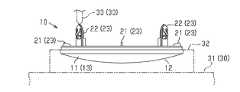
図1及び図2に示すように、エンブレム10は、車両の図示しないフロントグリルであって、左右方向の中央部分に設けられた開口部に取付けられて、フロントグリル、ひいては車両の前部を装飾するものである。 As shown in FIGS. 1 and 2, the
エンブレム10は、基体部11及び複数の付加部を備えている。基体部11は、エンブレム10の骨格をなす部分であり、上下方向よりも左右方向に寸法の大きな略楕円形の板状をなしている。基体部11は、車両前方へ膨らむように湾曲している。基体部11は、自身の外表面のうちの表面を、意匠面12として有している。図4に示すように、基体部11は、樹脂材料を成形してなる樹脂成形部13によって構成されている。基体部11は、ABS(アクリロニトリル-ブタジエン-スチレン共重合体)等の硬質樹脂材料を用い、一般的な樹脂成形法、本実施形態では射出成形法によって形成されている。 The
図1及び図2に示すように、複数の付加部は、複数の補強部21と複数の取付部22とを備えている。これらの補強部21及び取付部22は、ABSによって上記基体部11とは別に形成されており、基体部11の外表面のうち意匠面12とは異なる箇所である裏面16に接続されている。 As shown in FIGS. 1 and 2 , the plurality of additional portions includes a plurality of
図4に示すように、各補強部21は、樹脂層21aが積層されてなる積層造形部23によって構成されている。なお、図示はしないが、各取付部22も、上記補強部21と同様に、樹脂層が積層されてなる積層造形部23によって構成されている。補強部21及び取付部22のいずれの積層造形部23も、3次元プリンタを用いた積層造形法によって造形されている。 As shown in FIG. 4, each reinforcing
各補強部21は、基体部11を補強するためのものであり、リブ等によって構成されている。図1及び図4に示すように、各補強部21は、基体部11の裏面16における外周部分であって、周方向に互いに離間した複数箇所に接続されている。 Each reinforcing
図1及び図2に示すように、各取付部22は、エンブレム10をフロントグリルに取付けるためのものであり、クリップ、ビス、係合爪等によって構成されている。複数の取付部22は、基体部11の裏面16における外周部分であって、周方向に互いに離間した複数箇所に接続されている。 As shown in FIGS. 1 and 2, each
複数の補強部21及び複数の取付部22は、互いに同様の態様で基体部11に接続されている。そのため、ここでは、補強部21の基体部11に対する接続態様について説明し、取付部22の基体部11に対する接続態様については説明を省略する。 The plurality of reinforcing
図4及び図5に示すように、基体部11は、その裏面16における外周部分であって、周方向に互いに離間した複数箇所に、各補強部21の接続を補助する接続補助部14を有している。そして、各補強部21は、対応する接続補助部14において基体部11に接続されている。 As shown in FIGS. 4 and 5, the
より詳しくは、各接続補助部14は嵌合部15を有している。接続補助部14毎の嵌合部15は、基体部11の裏面16において開口し、かつ意匠面12側へ凹む凹部によって構成されている。各補強部21は、上記嵌合部15に嵌合し得る被嵌合部24を一端部に有している。各補強部21は、自身の被嵌合部24が、対応する嵌合部15に対し嵌合された状態で基体部11に接続されている。各被嵌合部24の外面は嵌合部15の内面に対し、隙間のない、又は少ない状態で密着している。 More specifically, each
次に、上記のように構成された本実施形態の作用について説明する。また、作用に伴い生ずる効果についても併せて説明する。
最初に、エンブレム10の製造方法について、図3を参照して説明する。この製造方法では、少なくとも基体部成形工程、スキャン工程及び付加部造形工程が行なわれる。Next, the operation of this embodiment configured as described above will be described. In addition, effects caused by the action will also be described.
First, a method of manufacturing the
基体部成形工程では、図示しない金型が用いられて、射出成形が行なわれる。型閉じされた金型に形成される成形空間であるキャビティに溶融状態の樹脂材料が充填される。この樹脂材料が硬化されることで、表面を意匠面12とするとともに、裏面16の外周部分の複数箇所に、凹部からなる嵌合部15を有する基体部11が成形される。ここで、仮に、積層造形法によって基体部11を造形すると、隣り合う樹脂層間に積層段差と呼ばれる段差が少なからず生ずる。しかし、射出成形法によって基体部11を成形することで、積層段差が発生せず、凸凹の少ない滑らかな外表面を有する基体部11を成形することができる。 In the base portion molding step, injection molding is performed using a mold (not shown). A cavity, which is a molding space formed in the closed mold, is filled with a molten resin material. By curing the resin material, the
スキャン工程では、上記のように成形された基体部11が、図示しない3次元スキャナによってスキャンされて、同基体部11の3次元データが作成される。すなわち、3次元スキャナから上記基体部11に対しレーザ光等が照射されて、同基体部11がスキャンされ、3次元の座標が取得される。この作業が繰り返されることで、基体部11から座標値を持つ点の集まりとして3次元データが得られる。 In the scanning step, the
付加部造形工程では、図3に示す3次元プリンタ30が用いられて、基体部11の嵌合部15に対し積層造形法が行なわれる。この積層造形法の実施に際し、基体部11の形状に関する上記3次元データから、補強部21及び取付部22の基体部11に対する接続位置が決定され、その接続位置に基づきノズル33の作動開始位置P1が設定される。 In the additional portion forming process, the three-
また、付加部造形工程では、補強部21及び取付部22のそれぞれの3次元形状を表す3次元データが準備される。この3次元データは、例えば、3次元CADによって作成されたものであってもよいし、3次元スキャナによって作成されたものであってもよい。 In addition, in the additional portion forming process, three-dimensional data representing the three-dimensional shapes of the reinforcing
3次元データを積層ピッチの薄い層に分けた積層データが作成される。積層データが、3次元プリンタ30を制御するためのプリンタ制御コードに変換された後、そのプリンタ制御コードが3次元プリンタ30に送られる。 Lamination data is created by dividing the three-dimensional data into thin layers with a lamination pitch. After the layered data is converted into a printer control code for controlling the three-
一方、3次元プリンタ30の造形ステージ31上に支持部材32が組付けられ、さらに上記支持部材32上に基体部11が載置される。この載置は、意匠面12を下側に位置させ、裏面16を上側に位置させた状態で行なわれる。このようにして、基体部11が、造形ステージ31上の予め定められた箇所に位置決めされた状態で配置される。 On the other hand, a
その後、3次元プリンタ30では、上記プリンタ制御コードに基づき、各部の作動が制御される。
ここで、3次元プリンタ30の初期状態では、造形ステージ31の原点を基準として、同造形ステージ31上にノズル33の作動開始位置P1が設定される。仮に、ノズル33がこの作動開始位置P1へ移動させられ、溶融状態の樹脂材料の押出しが開始されると、エンブレム10の全体、すなわち、基体部11、補強部21及び取付部22の全部が積層造形法によって造形されることになる。After that, in the three-
Here, in the initial state of the three-
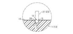
しかし、本実施形態では、図5に示すように、補強部21等の基体部11に対する上記接続位置、この場合、嵌合部15の内底面17の角部にノズル33の作動開始位置P1が設定される。設定された作動開始位置P1は、造形ステージ31の上面から上方へ離れている。そして、ノズル33が、上記のように設定された作動開始位置P1へ移動させられる。その移動後にノズル33からの樹脂材料の押出しが上記作動開始位置P1にて開始される。その後も、ノズル33が水平方向へ移動させられながら、すなわち、造形ステージ31とノズル33とが樹脂層21aに沿う方向へ相対移動させられながら、溶融状態の樹脂材料がノズル33から押出される。押出された樹脂材料は、嵌合部15の内底面17に対し接合する。この樹脂材料が硬化することで、図4に示すように、上記積層ピッチの厚みを有する樹脂層21aが内底面17上に形成される。樹脂層21aの形成後に、造形ステージ31が上記積層ピッチだけ降下させられる、又は、ノズル33が上記積層ピッチだけ上昇させられる。すなわち、造形ステージ31及びノズル33が樹脂層21aの厚み方向へ相対移動させられる。上記樹脂層21a上に溶融状態の樹脂材料が積み重ねられて別の樹脂層21aが形成される。このように、造形ステージ31を降下させて、又はノズル33を上昇させて、ノズル33を水平方向へ移動させることで、樹脂層21aが積層される。基体部11に対し接続した状態の補強部21及び取付部22が造形されて、目的とするエンブレム10が得られる。 However, in the present embodiment, as shown in FIG. 5, the operation start position P1 of the
補強部21及び取付部22は、上記のように積層造形法によって形成される。そのため、補強部21及び取付部22が、射出成形法等の一般的な樹脂成形法では成形が難しい複雑な形状を有していても、積層造形法では造形が可能である。 The reinforcing
また、基体部11は、上述したように射出成形法によって形成される。そのため、基体部11が、補強部21及び取付部22と同様、3次元プリンタ30を用いて造形された積層造形部23によって構成される場合に比べ、短時間で同基体部11を形成することができる。 Also, the
このように、本実施形態によると、エンブレム10の全体が積層造形部23によって構成される場合に比べ、同エンブレム10の生産性を高めることができる。
また、車種間で基体部11が共通していて、車種間で補強部21及び取付部22の形状や大きさが異なっている場合には、補強部21及び取付部22の種類を変更することで、車種毎に、対応するエンブレム10を製造することができる。As described above, according to the present embodiment, the productivity of the
Further, when the
得られたエンブレム10では、図4及び図5に示すように、補強部21及び取付部22が接続補助部14において基体部11に接続されることにより、補強部21及び取付部22の基体部11に対する接続が補助される。そのため、接続補助部14が設けられることなく基体部11の裏面16に直接接続される場合に比べ、補強部21及び取付部22の基体部11に対する接続を強固に行なうことができる。 In the obtained
特に、本実施形態では、補強部21及び取付部22の接続補助部14に対する接続は、被嵌合部24が嵌合部15に対し嵌合された状態でなされている。そのため、嵌合部15の内面が被嵌合部24の外面に接触することで、同被嵌合部24の動きが嵌合部15によって規制される。また、上記嵌合がなされない状態で補強部21及び取付部22が接続補助部14に接続される場合に比べ、補強部21及び取付部22の接続補助部14に対する接触面積が増大し、同基体部11に対する接続をより強固に行なうことができる。 In particular, in the present embodiment, the reinforcing
得られたエンブレム10では、基体部11が複数の補強部21によって補強され、同基体部11、ひいてはエンブレム10の厚み方向の強度が高められる。そのため、エンブレム10が厚み方向へ変形しにくい。 In the obtained
そして、上記エンブレム10は、車両のフロントグリルにおける開口部に配置され、複数の取付部22において、フロントグリルに取付けられる。
このようにして、フロントグリルに取付けられたエンブレム10を車両前方から見た場合、基体部11の外表面のうちの意匠面12が見えるが、裏面16に接続された補強部21及び取付部22は見えない、又は見えにくい。そのため、補強部21及び取付部22が見えることによるエンブレム10の見栄えの低下を抑制することができる。The
Thus, when the
また、基体部11の裏面16に設けられている接続補助部14もまた車両前方から見えない。そのため、接続補助部14が見えることによるエンブレム10の見栄えの低下を抑制することができる。 Also, the
本実施形態によると、上記以外にも、次の効果が得られる。
・基体部11が共通していて、付加部(補強部21、取付部22)の形状、大きさ等が互いに異なる複数種類のエンブレム10の全体を射出成形法によって成形する場合、金型がエンブレム10の種類と同じ数必要となる。それらの金型を検討したり製造したりする分、工数が増え、金型の製造費用が嵩む。According to this embodiment, the following effects are obtained in addition to the above.
・When a plurality of types of
この点、本実施形態では、エンブレム10のうち、形状及び大きさが共通している基体部11のみを射出成形で成形するようにしている。そのため、金型としては、基体部11を成形するための金型を1種類準備するだけですみ、金型の検討のための工数と、製作のための費用とを削減することができる。 In this regard, in the present embodiment, only the
・エンブレム10のうち補強部21及び取付部22のみを積層造形しているため、造形材料の使用量が少なくてすみ、材料のコストを低減することができる。
なお、上記実施形態は、これを以下のように変更した変形例として実施することもできる。上記実施形態及び以下の変形例は、技術的に矛盾しない範囲で互いに組み合わせて実施することができる。・Since only the reinforcing
It should be noted that the above-described embodiment can also be implemented as a modified example in which this is changed as follows. The above embodiments and the following modifications can be combined with each other within a technically consistent range.
・嵌合部15において、被嵌合部24との嵌合により、同被嵌合部24が接触される面の少なくとも一部が、基体部11のうち、少なくとも嵌合部15の周りの部分よりも粗い粗面18によって構成されてもよい。図6は、嵌合部15の内底面17が粗面18に形成されている変形例を示している。このようにすることで、内底面17が凹凸の少ない滑らかな面に形成される場合に比べ、同内底面17の表面積が増える。 At least a portion of the surface of the
そのため、嵌合部15において、内底面17を含む全ての内面が滑らかな面によって構成される場合に比べ、被嵌合部24が嵌合部15に対し、より広い面に対し接触した状態で接続されることとなる。また、被嵌合部24はアンカー効果によって、粗面18に対し機械的に結合された状態となって、基体部11に接続される。そのため、補強部21及び取付部22の基体部11に対する接続をより一層強固に行なうことができる。 Therefore, in the
・上記3次元スキャナを、3次元プリンタ30を有する積層造形装置内に組込み、造形ステージ31上に配置された基体部11を3次元スキャナによってスキャンして、基体部11の3次元データを作成してもよい。この場合には、基体部11を造形ステージ31から取り外すことなく、3次元プリンタ30による積層造形を行なうことができる。そのため、造形ステージ31とは異なる箇所で3次元スキャナによるスキャンを行ない、その後に、基体部11を造形ステージ31に配置する場合よりも高い精度で、補強部21及び取付部22を造形することが可能となる。 - The three-dimensional scanner is incorporated in a layered modeling apparatus having a three-
・基体部11は単一の部材によって構成されてもよいし、複数の部材によって構成されてもよい。
・上記図6の変形例において、嵌合部15の内面のうち、粗面18により構成される箇所は、被嵌合部24との嵌合により同被嵌合部24に接触する面の少なくとも一部であればよい。この条件を満たす範囲で、粗面18が形成される箇所が上記実施形態とは異なる箇所に変更されてもよい。- The
- In the modified example of FIG. Part of it is fine. As long as this condition is satisfied, the location where the
・嵌合部15が突部によって構成され、被嵌合部24が凹部によって構成されて、被嵌合部24が嵌合部15に外嵌された状態で接続されてもよい。
・補強部21及び取付部22のうちの一方のみが付加部とされて、積層造形部23によって構成されてもよい。The
- Only one of the
・基体部11及び付加部が、ABSとは異なる樹脂材料、例えばPP(ポリプロピレン)によって形成されてもよい。
・基体部11及び付加部は、同一の樹脂材料によって形成されるのが接合性の点で好ましいが、接合できる材料であることを条件に、異なる種類の樹脂材料によって形成されてもよい。- The
The
・付加部の基体部11に対する接続箇所が、基体部11の外表面のうち、意匠面12とは異なる箇所であることを条件に、上記実施形態(裏面16)とは異なる箇所に変更されてもよい。 ・On the condition that the connecting portion of the additional portion to the
・上記車両用樹脂製品は、車両の外装品であることを条件に、上記エンブレム10とは異なる樹脂製品に適用されてもよい。
また、上記車両用樹脂製品は、車両の内装品に適用されてもよい。例えば、ドアのアームレストの上部カバー、シフトパネル等がこれに該当する。- The vehicle resin product may be applied to a resin product different from the
Moreover, the resin product for vehicles may be applied to the interior parts of a vehicle. For example, the upper cover of the armrest of the door, the shift panel, etc. correspond to this.
・上記付加部の積層造形法としては、上記実施形態の溶融樹脂積層法(材料押出法)に限らず、他の積層造形法を適宜採用可能である。例えば、光硬化性樹脂をヘッドから吹付け、紫外線で硬化させながら積層する材料噴射法、敷き詰められた粉末にレーザ光を当てて焼結させ積層する粉末床溶融結合法等がこれに該当する。 The lamination molding method for the additional portion is not limited to the molten resin lamination method (material extrusion method) of the above embodiment, and other lamination molding methods can be appropriately employed. For example, this includes a material injection method in which a photocurable resin is sprayed from a head and laminated while being cured with ultraviolet rays, and a powder bed fusion method in which a laser beam is applied to the spread powder to sinter and laminate.
10…エンブレム(車両用樹脂製品)、11…基体部、12…意匠面、13…樹脂成形部、14…接続補助部、15…嵌合部、18…粗面、21…補強部、21a…樹脂層、22…取付部、23…積層造形部、24…被嵌合部、30…3次元プリンタ、31…造形ステージ、33…ノズル、P1…作動開始位置。 DESCRIPTION OF
Claims (3)
Translated fromJapanese前記基体部の前記外表面の前記意匠面とは異なる箇所に接続された樹脂製の付加部と
を備える車両用樹脂製品の製造方法であって、
前記基体部を射出成形法により成形する基体部成形工程と、
前記基体部成形工程により成形された前記基体部の外表面における前記意匠面とは異なる箇所に対し、3次元プリンタを用いて樹脂層を積層することにより、前記箇所に接続された状態の前記付加部を造形する付加部造形工程とを備え、
前記付加部は、前記基体部を補強する補強部、及び前記基体部を車両に取付けるための取付部の少なくとも一方であり、
前記基体部成形工程は、前記箇所に前記付加部の接続を補助する接続補助部を有する前記基体部を成形し、
前記接続補助部は、前記意匠面とは異なる外表面である前記基体部の裏面において開口し、かつ前記意匠面側へ凹む嵌合部であり、
前記付加部造形工程は、前記嵌合部に対し嵌合された状態で前記接続補助部に接続される被嵌合部を有する前記付加部を造形する車両用樹脂製品の製造方法。a base portion made of resin having a part of its outer surface as a design surface;
A method for manufacturing a resin product for a vehicle, comprising: an additional portion made of resin connected to a portion different from the design surface of the outer surface of the base portion;
a base portion molding step of molding the base portion by an injection molding method;
By laminating a resin layer using a three-dimensional printer on a portion different from the design surface on the outer surface of the base body molded in the base body molding step, the addition in a state of being connected to the said portion and an additional part forming process for forming the part,
the additional portion is at least one of a reinforcing portion that reinforces the base portion and a mounting portion for mounting the base portion to a vehicle;
The base portion forming step includes forming the base portion having a connection auxiliary portion for assisting connection of the additional portion at the location,
The auxiliary connection portion is a fitting portion that is open on the back surface of the base portion, which is an outer surface different from the design surface, and is recessed toward the design surface,
The additional portion shaping step includes shaping the additional portion having a fitted portion connected to the connection auxiliary portion in a state of being fitted to the fitting portion .
前記付加部造形工程に先立ち、前記基体部成形工程で成形された前記基体部をスキャンすることにより、同基体部の3次元データを作成するスキャン工程をさらに備え、
前記付加部造形工程では、前記スキャン工程で作成された前記基体部の前記3次元データから前記付加部の前記基体部に対する接続位置を決定し、前記接続位置に基づき前記ノズルの作動開始位置を設定し、前記ノズルを前記作動開始位置へ移動させて前記樹脂材料の押出しを開始させる請求項1又は2に記載の車両用樹脂製品の製造方法。In the additional portion forming step, a forming stage on which the base portion is placed and a nozzle for extruding a resin material in a molten state are relatively moved to form the resin layer on the base portion. The additional portion is formed by laminating resin layers,
Further comprising a scanning step of creating three-dimensional data of the base portion formed in the base portion forming step, prior to the additional portion forming step, by scanning the base portion formed in the base portion forming step;
In the additional portion forming step, a connection position of the additional portion with respect to the base portion is determined from the three-dimensional data of the base portion created in the scanning step, and an operation start position of the nozzle is set based on the connection position. and moving the nozzle tothe operation start position to start extruding the resin material.
Priority Applications (1)
| Application Number | Priority Date | Filing Date | Title |
|---|---|---|---|
| JP2019118221AJP7207197B2 (en) | 2019-06-26 | 2019-06-26 | Method for manufacturing resin products for vehicles |
Applications Claiming Priority (1)
| Application Number | Priority Date | Filing Date | Title |
|---|---|---|---|
| JP2019118221AJP7207197B2 (en) | 2019-06-26 | 2019-06-26 | Method for manufacturing resin products for vehicles |
Publications (2)
| Publication Number | Publication Date |
|---|---|
| JP2021003829A JP2021003829A (en) | 2021-01-14 |
| JP7207197B2true JP7207197B2 (en) | 2023-01-18 |
Family
ID=74098064
Family Applications (1)
| Application Number | Title | Priority Date | Filing Date |
|---|---|---|---|
| JP2019118221AActiveJP7207197B2 (en) | 2019-06-26 | 2019-06-26 | Method for manufacturing resin products for vehicles |
Country Status (1)
| Country | Link |
|---|---|
| JP (1) | JP7207197B2 (en) |
Citations (4)
| Publication number | Priority date | Publication date | Assignee | Title |
|---|---|---|---|---|
| JP2015526315A (en) | 2012-07-04 | 2015-09-10 | レゴ エー/エス | Method used for the manufacture of plastic products and products produced by the method |
| JP2018069570A (en) | 2016-10-28 | 2018-05-10 | 株式会社リコー | 3D modeling apparatus, mounting member, and manufacturing method of 3D model |
| JP2018524215A (en) | 2015-07-13 | 2018-08-30 | ストラタシス リミテッド | Operation of printing nozzles in additive manufacturing and equipment |
| JP2018138358A (en) | 2017-02-24 | 2018-09-06 | セイコーエプソン株式会社 | Three-dimensional structure manufacturing apparatus and three-dimensional structure manufacturing method |
- 2019
- 2019-06-26JPJP2019118221Apatent/JP7207197B2/enactiveActive
Patent Citations (4)
| Publication number | Priority date | Publication date | Assignee | Title |
|---|---|---|---|---|
| JP2015526315A (en) | 2012-07-04 | 2015-09-10 | レゴ エー/エス | Method used for the manufacture of plastic products and products produced by the method |
| JP2018524215A (en) | 2015-07-13 | 2018-08-30 | ストラタシス リミテッド | Operation of printing nozzles in additive manufacturing and equipment |
| JP2018069570A (en) | 2016-10-28 | 2018-05-10 | 株式会社リコー | 3D modeling apparatus, mounting member, and manufacturing method of 3D model |
| JP2018138358A (en) | 2017-02-24 | 2018-09-06 | セイコーエプソン株式会社 | Three-dimensional structure manufacturing apparatus and three-dimensional structure manufacturing method |
Also Published As
| Publication number | Publication date |
|---|---|
| JP2021003829A (en) | 2021-01-14 |
Similar Documents
| Publication | Publication Date | Title |
|---|---|---|
| CN103635336B (en) | External module, manufacturing method thereof, and modular housing part | |
| CN101119833B (en) | Vehicle component and method for making a vehicle component | |
| JP2022133446A (en) | Sound absorbing panel material for vehicle | |
| JP2008037026A (en) | Interior panel and injection molding method | |
| US20190255747A1 (en) | Trim component for covering an interior space of a means for transporting passengers as well as method for producing such a trim component | |
| JP5738610B2 (en) | Composite and production method thereof | |
| JP7207197B2 (en) | Method for manufacturing resin products for vehicles | |
| JP6844766B2 (en) | Manufacturing method of decorative resin products | |
| CN101262993B (en) | Composite part having a multicoloured surface and its production method | |
| JP2019166652A (en) | Manufacturing method of formed structure | |
| JP5814788B2 (en) | Manufacturing method of resin skin material | |
| JP2013189074A (en) | Vehicle seat | |
| JP2010227302A (en) | Seat pad and production method thereof | |
| JP2015098141A (en) | Method of producing resin-made skin material | |
| JP3137778U (en) | Mold for molding | |
| JP2011195080A (en) | Vehicular exterior resin panel | |
| JP3693790B2 (en) | Manufacturing method of resin molded body and manufacturing apparatus therefor | |
| JP2021000742A (en) | Interior material for vehicle and manufacturing method of interior material for vehicle | |
| JP2021142703A (en) | Molded structure | |
| JP5205138B2 (en) | Interior parts for vehicles and manufacturing method thereof | |
| JP6188559B2 (en) | Manufacturing method of vehicle ceiling material and heating press mold used therefor | |
| JP2005305917A (en) | Foam molded part and method for manufacturing the same | |
| JP2009078459A (en) | Molding method for molding and its master model | |
| JP4900595B2 (en) | Manufacturing method of foamed resin products | |
| JP5697241B2 (en) | Manufacturing method of resin molded products |
Legal Events
| Date | Code | Title | Description |
|---|---|---|---|
| A621 | Written request for application examination | Free format text:JAPANESE INTERMEDIATE CODE: A621 Effective date:20210630 | |
| A977 | Report on retrieval | Free format text:JAPANESE INTERMEDIATE CODE: A971007 Effective date:20220425 | |
| A131 | Notification of reasons for refusal | Free format text:JAPANESE INTERMEDIATE CODE: A131 Effective date:20220510 | |
| A521 | Request for written amendment filed | Free format text:JAPANESE INTERMEDIATE CODE: A523 Effective date:20220617 | |
| A02 | Decision of refusal | Free format text:JAPANESE INTERMEDIATE CODE: A02 Effective date:20220719 | |
| A521 | Request for written amendment filed | Free format text:JAPANESE INTERMEDIATE CODE: A523 Effective date:20221019 | |
| C60 | Trial request (containing other claim documents, opposition documents) | Free format text:JAPANESE INTERMEDIATE CODE: C60 Effective date:20221019 | |
| A911 | Transfer to examiner for re-examination before appeal (zenchi) | Free format text:JAPANESE INTERMEDIATE CODE: A911 Effective date:20221027 | |
| C21 | Notice of transfer of a case for reconsideration by examiners before appeal proceedings | Free format text:JAPANESE INTERMEDIATE CODE: C21 Effective date:20221101 | |
| TRDD | Decision of grant or rejection written | ||
| A01 | Written decision to grant a patent or to grant a registration (utility model) | Free format text:JAPANESE INTERMEDIATE CODE: A01 Effective date:20221206 | |
| A61 | First payment of annual fees (during grant procedure) | Free format text:JAPANESE INTERMEDIATE CODE: A61 Effective date:20221219 | |
| R151 | Written notification of patent or utility model registration | Ref document number:7207197 Country of ref document:JP Free format text:JAPANESE INTERMEDIATE CODE: R151 |