JP7207165B2 - Packet processor and network system - Google Patents
Packet processor and network systemDownload PDFInfo
- Publication number
- JP7207165B2 JP7207165B2JP2019098260AJP2019098260AJP7207165B2JP 7207165 B2JP7207165 B2JP 7207165B2JP 2019098260 AJP2019098260 AJP 2019098260AJP 2019098260 AJP2019098260 AJP 2019098260AJP 7207165 B2JP7207165 B2JP 7207165B2
- Authority
- JP
- Japan
- Prior art keywords
- priority
- packet
- mfh
- packets
- priority packet
- Prior art date
- Legal status (The legal status is an assumption and is not a legal conclusion. Google has not performed a legal analysis and makes no representation as to the accuracy of the status listed.)
- Active
Links
Images


Classifications
- H—ELECTRICITY
- H04—ELECTRIC COMMUNICATION TECHNIQUE
- H04L—TRANSMISSION OF DIGITAL INFORMATION, e.g. TELEGRAPHIC COMMUNICATION
- H04L45/00—Routing or path finding of packets in data switching networks
- H04L45/74—Address processing for routing
- H—ELECTRICITY
- H04—ELECTRIC COMMUNICATION TECHNIQUE
- H04L—TRANSMISSION OF DIGITAL INFORMATION, e.g. TELEGRAPHIC COMMUNICATION
- H04L49/00—Packet switching elements
- H04L49/25—Routing or path finding in a switch fabric
- H—ELECTRICITY
- H04—ELECTRIC COMMUNICATION TECHNIQUE
- H04L—TRANSMISSION OF DIGITAL INFORMATION, e.g. TELEGRAPHIC COMMUNICATION
- H04L45/00—Routing or path finding of packets in data switching networks
- H04L45/42—Centralised routing
- H—ELECTRICITY
- H04—ELECTRIC COMMUNICATION TECHNIQUE
- H04L—TRANSMISSION OF DIGITAL INFORMATION, e.g. TELEGRAPHIC COMMUNICATION
- H04L47/00—Traffic control in data switching networks
- H04L47/10—Flow control; Congestion control
- H04L47/24—Traffic characterised by specific attributes, e.g. priority or QoS
- H04L47/2466—Traffic characterised by specific attributes, e.g. priority or QoS using signalling traffic
- H—ELECTRICITY
- H04—ELECTRIC COMMUNICATION TECHNIQUE
- H04L—TRANSMISSION OF DIGITAL INFORMATION, e.g. TELEGRAPHIC COMMUNICATION
- H04L47/00—Traffic control in data switching networks
- H04L47/10—Flow control; Congestion control
- H04L47/28—Flow control; Congestion control in relation to timing considerations
- H—ELECTRICITY
- H04—ELECTRIC COMMUNICATION TECHNIQUE
- H04L—TRANSMISSION OF DIGITAL INFORMATION, e.g. TELEGRAPHIC COMMUNICATION
- H04L47/00—Traffic control in data switching networks
- H04L47/50—Queue scheduling
- H04L47/62—Queue scheduling characterised by scheduling criteria
- H04L47/6215—Individual queue per QOS, rate or priority
- H—ELECTRICITY
- H04—ELECTRIC COMMUNICATION TECHNIQUE
- H04L—TRANSMISSION OF DIGITAL INFORMATION, e.g. TELEGRAPHIC COMMUNICATION
- H04L49/00—Packet switching elements
- H04L49/30—Peripheral units, e.g. input or output ports
- H04L49/3018—Input queuing
- H—ELECTRICITY
- H04—ELECTRIC COMMUNICATION TECHNIQUE
- H04L—TRANSMISSION OF DIGITAL INFORMATION, e.g. TELEGRAPHIC COMMUNICATION
- H04L69/00—Network arrangements, protocols or services independent of the application payload and not provided for in the other groups of this subclass
- H04L69/22—Parsing or analysis of headers
Landscapes
- Engineering & Computer Science (AREA)
- Computer Networks & Wireless Communication (AREA)
- Signal Processing (AREA)
- Computer Security & Cryptography (AREA)
- Data Exchanges In Wide-Area Networks (AREA)
Description
Translated fromJapanese本発明は、パケットを処理する装置およびパケットを伝送するネットワークシステムに係わる。 The present invention relates to an apparatus for processing packets and a network system for transmitting packets.
近年、第5世代移動通信システム(5G)を実現するための技術の1つとして、無線基地局(CU:Centralized Unit)および無線アンテナ局(DU:Distributed Unit)を含むMFH(Mobile Front Haul)ネットワークが検討されている。MFHネットワークは、無線基地局と無線アンテナ局との間で、無線通信のための信号を伝送する。なお、この無線基地局は、BBU(Base Band Unit)と呼ばれることがある。また、この無線アンテナ局は、RRH(Remote Radio Head)と呼ばれることがある。 In recent years, MFH (Mobile Front Haul) network including radio base stations (CU: Centralized Unit) and radio antenna stations (DU: Distributed Unit) is one of the technologies for realizing the fifth generation mobile communication system (5G). is being considered. The MFH network transmits signals for radio communication between radio base stations and radio antenna stations. Note that this radio base station is sometimes called a BBU (Base Band Unit). Also, this radio antenna station is sometimes called an RRH (Remote Radio Head).
MFHネットワークは、レイヤ2のパケットを伝送する。このため、MFHネットワークのためのパスおよび他のネットワーク(MBH(Mobile Back Haul)ネットワークまたは有線ネットワーク等)のパスが通信リソースを共有することがある。これにより、通信リソースの効率的な利用が実現される。 The MFH network carries
ただし、MFHネットワークは、他のネットワークと比較して、遅延に係わる要求が厳しい。このため、他のネットワーク上で伝送されるパケットと比較して、MFHネットワーク上で伝送されるパケットを優先的に処理する優先制御が提案されている。なお、以下の記載では、MFHネットワーク上で伝送されるパケットを「MFHパケット」又は「優先パケット(高優先パケット)」と呼ぶことがある。また、他のネットワーク上で伝送されるパケットを「非MFHパケット」又は「非優先パケット(低優先パケット)」と呼ぶことがある。 However, MFH networks have stricter delay requirements than other networks. For this reason, priority control has been proposed for preferentially processing packets transmitted over the MFH network compared to packets transmitted over other networks. In the following description, packets transmitted on the MFH network may be called "MFH packets" or "priority packets (high priority packets)". Packets transmitted over other networks are sometimes called “non-MFH packets” or “non-priority packets (low-priority packets)”.
例えば、TAS(Time Aware Shaper)は、非MFHパケットに対してゲート制御を行う。具体的には、TASは、ネットワーク内の各ノードに実装され、ゲートおよびゲートを制御する機能を含む。そして、TASは、MFHパケットを転送するときに、ゲートを閉じることにより非MFHパケットの出力(或いは、転送)を停止する。このとき、非MFHパケットは、バッファに保存される。そして、MFHパケットの転送が終了すると、ゲートが開かれ、バッファに保存されていた非MFHパケットが出力される。この機能により、MFHパケットの遅延が抑制される。なお、TASは、IEEE802.1QBvに規定されている。 For example, a TAS (Time Aware Shaper) gates non-MFH packets. Specifically, the TAS is implemented in each node in the network and includes gates and functions to control the gates. Then, when transferring MFH packets, the TAS stops outputting (or transferring) non-MFH packets by closing the gate. At this time, non-MFH packets are stored in the buffer. When the transfer of the MFH packet is completed, the gate is opened and the non-MFH packet stored in the buffer is output. This function reduces the delay of MFH packets. Note that TAS is defined in IEEE802.1QBv.
なお、特許文献1には、高優先パケットの出力遅延を抑制するパケット処理装置が記載されている。また、特許文献2~5にも関連する技術が記載されている。 Note that
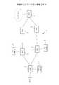
TASは、上述したように、MFHパケットがノードを通過するときにゲートを閉じることで、非MFHパケットの出力を停止する。このとき、図1(a)に示すように、ゲートを閉じる期間の前後にそれぞれマージン期間が設定される。ここで、マージン期間においても、非MFHパケットの出力は停止される。すなわち、各MHFパケットに対して、非MFHパケットの出力を停止するマージン期間が設定される。このため、TASを通過するMFHパケットの頻度が高くなると、マージン期間により非MFHパケットを出力できない期間も長くなり、非MFH通信の帯域が減少する。 The TAS stops outputting non-MFH packets by closing the gate as the MFH packets pass through the node, as described above. At this time, as shown in FIG. 1A, margin periods are set before and after the gate closing period. Here, the output of non-MFH packets is stopped even during the margin period. That is, a margin period for stopping output of non-MFH packets is set for each MHF packet. Therefore, when the frequency of MFH packets passing through the TAS increases, the period during which non-MFH packets cannot be output increases due to the margin period, and the band for non-MFH communication decreases.
また、MFHパケット間の間隔が短いときは、TASのゲート制御が追従できないことがある。このため、MFHパケット間の間隔が所定の閾値より短いときは、図1(b)に示すように、TASは、2つのMFHパケットの間の期間(すなわち、ギャップ期間)においてゲートを閉じたまま保持する。よって、このことによっても、非MFH通信の帯域が減少することがある。 Also, when the interval between MFH packets is short, TAS gate control may not be able to follow. Therefore, when the interval between MFH packets is less than a predetermined threshold, the TAS keeps the gate closed in the period between two MFH packets (i.e., the gap period), as shown in FIG. 1(b). Hold. Therefore, this may also reduce the bandwidth for non-MFH communication.
本発明の1つの側面に係わる目的は、優先度の異なるパケットを伝送するネットワークにおいて、優先度の低いパケットを伝送するための通信帯域を増加させることである。 An object according to one aspect of the present invention is to increase the communication bandwidth for transmitting low priority packets in a network that transmits packets with different priorities.
本発明の1つの態様のパケット処理装置は、優先パケットおよび前記優先パケットより優先度の低い非優先パケットを伝送するネットワークにおいて、前記優先パケットおよび前記非優先パケットを処理する。このパケット処理装置は、非優先パケットを格納する非優先パケット格納部と、前記非優先パケット格納部の出力側に設けられるゲートと、優先パケットを格納する複数の優先パケット格納部と、前記パケット処理装置が優先パケットを受信したときに、前記受信優先パケットを、前記受信優先パケットが伝送される経路の送信元と宛先との間の遅延時間に対応する優先パケット格納部に格納する振分け部と、各優先パケット格納部に対して異なる読出し間隔を設定するタイミング設定部と、前記タイミング設定部により設定される読出し間隔に従って前記複数の優先パケット格納部から優先パケットを読み出して出力する転送タイミング制御部と、前記転送タイミング制御部により優先パケットが出力されるタイミングに応じて前記ゲートを制御するゲート制御部とを備える。前記転送タイミング制御部は、前記複数の優先パケット格納部の中の1つの優先パケット格納部から優先パケットを読み出して出力するときに、他の優先パケット格納部からも優先パケットを読み出して出力する。 A packet processing device according to one aspect of the present invention processes a priority packet and a non-priority packet in a network that transmits a priority packet and a non-priority packet having a lower priority than the priority packet. This packet processing device comprises: a non-priority packet storage section for storing non-priority packets; a gate provided on the output side of the non-priority packet storage section; a plurality of priority packet storage sections for storing priority packets; a sorting unit that, when a device receives a priority packet, stores the reception priority packet in a priority packet storage unit that corresponds to a delay time between a source and a destination of a route along which the reception priority packet is transmitted; a timing setting unit for setting different read intervals for each priority packet storage unit; and a transfer timing control unit for reading and outputting priority packets from the plurality of priority packet storage units according to the read intervals set by the timing setting unit. and a gate control unit for controlling the gate according to the timing at which the priority packet is output by the transfer timing control unit. The transfer timing control unit, when reading and outputting a priority packet from one of the plurality of priority packet storage units, also reads and outputs the priority packet from other priority packet storage units.
上述の態様によれば、優先度の異なるパケットを伝送するネットワークにおいて、優先度の低いパケットを伝送するための通信帯域が増加する。 According to the above aspect, in a network that transmits packets with different priorities, the communication band for transmitting packets with low priority is increased.
図2は、本発明の実施形態に係わる中継ネットワークの一例を示す。中継ネットワーク1は、複数のパケットスイッチ装置2を含み、レイヤ2パケットを伝送する。すなわち、各パケットスイッチ装置2は、レイヤ2パケットを中継する。 FIG. 2 shows an example of a relay network according to an embodiment of the invention. A
中継ネットワーク1は、レイヤ2パケットを伝送する任意の回線を収容し得る。この例では、中継ネットワーク1は、無線アンテナ局(DUまたはRRH)3と基地局装置(CUまたはBBU)4との間に設定されるMFH回線を収容する。無線アンテナ局3は、1または複数の無線端末を収容し得る。基地局装置4は、無線アンテナ局3と各無線端末との間の無線リソースのスケジューリングを行う。なお、無線アンテナ局3と基地局装置4との間では、情報またはデータは、MFHパケットに格納されて伝送される。また、以下の記載では、無線アンテナ局3と基地局装置4との間に設定されるパスを「MFH回線」と呼ぶことがある。 The
中継ネットワーク1は、MFH回線以外の回線も収容する。例えば、MBH回線および他の有線ネットワークの情報またはデータを伝送する回線などが中継ネットワーク1に収容される。以下の記載では、MFH回線以外の回線を介して伝送されるパケットを「非MFHパケット」と呼ぶことがある。 The
ここで、非MFHパケットと比較して、MFHパケットの遅延に係わる要求は厳しい。このため、パケットスイッチ装置2は、非MFHパケットと比較して、MFHパケットを優先的に処理する優先制御機能を備える。 Here, compared to non-MFH packets, the delay requirements for MFH packets are strict. Therefore, the
図3は、パケットスイッチ装置2の一例を示す。パケットスイッチ装置2は、図3に示すように、スケジューリング部11、非MFHキュー12、TAS機能13を備える。そして、パケットスイッチ装置2は、MFHフローおよび非MFHフローを処理する。MFHフローは、この実施例では、各無線アンテナ局(DU)から基地局装置(CU)に向かうMFHパケットを表す。また、非MFHフローは、非MFHパケットを伝送する。 FIG. 3 shows an example of the
スケジューリング部11は、各MFHパケットの転送タイミングを制御する。この実施例では、スケジューリング部11は、DU毎に、各MFHパケットの転送タイミングを制御する。非MFHキュー12は、非MFHパケットを一時的に格納する。 The
TAS機能13は、ゲート制御部13aおよびゲート13bを備える。ゲート制御部13aは、MFHパケットの転送に応じてゲート13bを制御する。たとえば、スケジューリング部11によりMFHパケットが出力されるときは、ゲート制御部13aは、ゲート13bを閉じる。この場合、非MFHキュー12に格納されている非MFHパケットは、ゲート13bを通過することは出来ない。すなわち、スケジューリング部11によりMFHパケットが出力されるときは、パケットスイッチ装置2は、非MFHパケットを出力しない。これにより、MFHパケットの優先制御が実現される。 The
図4は、MFHパケットの遅延時間について説明する図である。MFHにおいては、エンド・エンド間での遅延時間が規定されている。一例としては、図4(a)に示すように、DUとCUとの間の伝送において許容される遅延時間は100μ秒である。すなわち、DUから送信されるMFHパケットは、100μ秒以内に、1または複数のパケットスイッチ装置2によりCUまで転送されることが要求される。このため、各パケットスイッチ装置2は、図3を参照して説明した優先制御を行う。 FIG. 4 is a diagram for explaining delay times of MFH packets. In MFH, an end-to-end delay time is defined. As an example, as shown in FIG. 4(a), the allowable delay time in transmission between DU and CU is 100 μs. That is, the MFH packet transmitted from the DU is required to be transferred to the CU by one or more
MFHパケットの遅延時間は、MFHパケットが通過する経路毎に異なる。図4(b)に示す例では、DU1とCUとの間の遅延時間は40μ秒であり、DU2とCUとの間の遅延時間は25μ秒である。なお、DUとCUとの間の遅延時間は、各DUの位置および各DUの性能などに依存する。 The delay time of the MFH packet differs for each route through which the MFH packet passes. In the example shown in FIG. 4(b), the delay time between DU1 and CU is 40 μs, and the delay time between DU2 and CU is 25 μs. Note that the delay time between the DU and the CU depends on the position of each DU, the performance of each DU, and the like.
このように、MFHパケットの遅延時間は、経路毎に異なる。換言すれば、経路毎に、許容される最大遅延時間に対する余裕度(或いは、マージン)が異なる。例えば、最大遅延時間が100μ秒である場合、DU1からCUに送信されるMFHパケットは60μ秒のマージンを有し、DU2からCUに送信されるMFHパケットは75μ秒のマージンを有する。この場合、パケットスイッチ装置2は、DU1からCUに送信されるMFHパケットを60μ秒まで遅延させることができ、DU2からCUに送信されるMFHパケットを75μ秒まで遅延させることができる。 Thus, the delay time of the MFH packet differs from route to route. In other words, the allowance (or margin) for the maximum allowable delay time differs for each path. For example, if the maximum delay time is 100 μs, MFH packets sent from DU1 to CU have a margin of 60 μs, and MFH packets sent from DU2 to CU have a margin of 75 μs. In this case, the
そこで、パケットスイッチ装置2は、この特徴を利用して、MFHパケットの転送タイミングを制御する。具体的には、パケットスイッチ装置2は、図3に示すゲート13bを閉じる時間が短くなるように、MFHパケットの転送タイミングを制御する。このとき、各MFHパケットの転送タイミングは、各DUとCUとの間の遅延時間が最大遅延時間を越えない範囲で制御される。 Therefore, the
図5は、MFHパケットの転送タイミングの制御の概要を示す。この例では、図3に示す非MFHキュー12に非MFHパケットが格納されているものとする。非MFHパケットは、ゲート13bが開いているときに、非MFHキュー12から読み出されて出力される。 FIG. 5 shows an overview of control of transfer timing of MFH packets. In this example, it is assumed that non-MFH packets are stored in the
パケットスイッチ装置2は、MFHパケット1~3を受信する。図5では、MFHパケット1~3は、MFH1~MFH3と表記されている。MFHパケット1~3は、それぞれ、経路R1~R3を介してDUからCUに伝送される。なお、経路R1、R2、R3の遅延時間は、それぞれ、A、B、Cであるものとする。 The
パケットスイッチ装置2が受信したMFHパケットをCUに向けて転送するときは、図3に示すTAS機能13は、ゲート13bを閉じる。このとき、各MFHパケットが転送される期間の前後にそれぞれマージン期間Mが設定される。そして、マージン期間Mにおいても、ゲート13bは閉じられる。 When forwarding the received MFH packet to the CU, the
ここで、パケットスイッチ装置2が本発明の実施形態に係わるスケジューリングを行わないものとする。この場合、各MFHパケット1~3に対してそれぞれマージン期間Mが設定される。このため、ゲート13bが閉状態に制御される時間が長くなり、非MFHパケットを転送するための時間が削減される。 Here, it is assumed that the
これに対して、スケジューリング部11は、ゲート13bを閉じる時間が短くなるように、MFHパケットの転送タイミングを制御する。この実施例では、スケジューリング部11は、MFHパケット1の転送タイミングを「D」だけ遅延させ、MFHパケット2の転送タイミングを「E」だけ遅延させている。このとき、MFHパケット1~3が連続して出力されるようにMFHパケット1、2を遅延させることが好ましい。ただし、遅延量Dは、経路R1の遅延時間Aと遅延量Dとの和がMFHパケットに対して規定されている最大遅延時間を越えない範囲で決定される。同様に、遅延量Eは、経路R2の遅延時間Bと遅延量Eとの和が最大遅延時間を越えない範囲で決定される。 In response to this, the
このようにしてMFHパケットの転送タイミングが調整されると、図5に示す例では、MFHパケット1の直後に設けられるマージン期間M、MFHパケット2の直前に設けられるマージン期間、MFHパケット2、3間に設けられるマージン期間M(または、ギャップ期間)が不要となる。これにより、スケジューリングを行わないケースと比較して、ゲート13bが閉じている期間の合計時間が短くなる。すなわち、非MFHパケットを転送するための通信帯域が増加する。具体的には、スケジューリングを行わないケースでは4個の非MFHパケットが転送されるが、スケジューリング部11がスケジューリングを行うケースでは5個の非MFHパケットが転送される。 When the transfer timing of the MFH packets is adjusted in this way, in the example shown in FIG. A margin period M (or a gap period) provided in between becomes unnecessary. As a result, the total time period during which the
なお、ゲート13bが閉じている期間の合計時間を短くするためには、マージン期間またはギャップ期間を削減することが好ましい。そして、マージン期間またはギャップ期間を削減するためには、MFHパケットが連続して転送されることが好ましい。よって、パケットスイッチ装置2は、各MFHパケットの遅延時間が最大遅延時間を越えない範囲で、受信したMFHパケットが可能な限り連続して転送されるように、各MFHパケットの出力タイミングを調整する。これにより、MFHパケットの優先制御および非MFHパケットの通信帯域の増加の双方が実現される。 In order to shorten the total time period during which the
<実施形態>
パケットスイッチ装置2は、MFHパケットの転送タイミングを調整するために、MFHフローの経路ごとに遅延マージン時間を計算する。経路は、図6に示す実施例では、各DCとCUとの間でパケットが転送される経路を表す。そして、遅延マージン時間は、経路の遅延時間に基づいて計算される。<Embodiment>
The
図6は、遅延マージン時間について説明する図である。図6に示す例では、中継ネットワークは、パケットスイッチ装置A~Cを備える。基地局装置(CU)は、パケットスイッチ装置Aに接続されている。各パケットスイッチ装置A~Cには、1または複数の無線アンテナ局(DU)が接続されている。すなわち、パケットスイッチ装置AにはDU1が接続され、パケットスイッチ装置B(SW_B)にはDU2、5、6が接続され、パケットスイッチ装置CにはDU3、4が接続されている。 FIG. 6 is a diagram explaining the delay margin time. In the example shown in FIG. 6, the relay network comprises packet switching devices AC. A base station unit (CU) is connected to the packet switching device A. FIG. One or more radio antenna stations (DU) are connected to each of the packet switching devices AC. That is, the packet switching device A is connected to DU1, the packet switching device B (SW_B) is connected to DU2, 5 and 6, and the packet switching device C is connected to DU3 and 4.
各DUとCUとの間の遅延時間は、予め測定されている。例えば、DU1とCUとの間の経路の遅延時間は10μ秒であり、DU2とCUとの間の経路の遅延時間は25μ秒である。なお、DU1とCUとの間の遅延時間は、公知の記述により測定される。また、この実施例では、各DUとCUとの間の経路は、DUにより一意に対応する。よって、以下の記載では、DUi(i=1~6)とCUとの間の経路を「経路DUi」と呼ぶことがある。 The delay time between each DU and CU is pre-measured. For example, the delay time of the path between DU1 and CU is 10 μs, and the delay time of the path between DU2 and CU is 25 μs. Note that the delay time between DU1 and CU is measured according to known descriptions. Also, in this example, the path between each DU and CU is uniquely associated with the DU. Therefore, in the following description, the path between DUi (i=1 to 6) and CU may be referred to as "path DUi".
パケットスイッチ装置2は、各経路について遅延マージン時間を計算する。ここで、経路DUiの遅延マージン時間は、下式で表される。
遅延マージン時間=最大遅延時間-経路DUiの遅延時間-調整係数
最大遅延時間は、通信規格などにより予め決められており、この実施例では100μ秒である。経路DUiの遅延時間は、予め測定されている。調整係数は、測定誤差、製造ばらつき、スケジューリング部11による遅延制御のための制御時間などを考慮して決定される定数であり、この実施例では10μ秒である。The
Delay margin time=maximum delay time−delay time of path DUi−adjustment coefficient The maximum delay time is predetermined according to communication standards and the like, and is 100 μsec in this embodiment. The delay time of the route DUi is measured in advance. The adjustment coefficient is a constant determined in consideration of measurement error, manufacturing variation, control time for delay control by the
例えば、DU1とCUとの間の経路の遅延時間は10μ秒である。したがって、この経路(すなわち、経路DU1)の遅延マージン時間は、80(=100-10-10)μ秒である。同様に、各経路の遅延マージン時間が計算される。各経路DU1~DU6の遅延マージン時間は、図6(b)に示す通りである。 For example, the path delay between DU1 and CU is 10 μs. Therefore, the delay margin time of this path (that is, path DU1) is 80 (=100-10-10) μs. Similarly, the delay margin time for each path is calculated. The delay margin times of the paths DU1 to DU6 are as shown in FIG. 6(b).
なお、遅延マージン時間は、例えば、各パケットスイッチ装置2により計算される。この場合、各パケットスイッチ装置2は、自分に接続されているDUとCUとの間の経路の遅延マージンを計算する。例えば、パケットスイッチ装置Aは、DU1とCUとの間の経路の遅延マージンを計算し、パケットスイッチ装置Bは、DU2、5、6とCUとの間の経路の遅延マージンをそれぞれ計算する。ただし、他の装置(例えば、基地局装置CU)が各経路の遅延マージン時間を計算し、その計算結果をそれぞれ対応する無線アンテナ局DUに配布してもよい。 The delay margin time is calculated by each
図7は、MFHパケットの転送タイミングの調整を実現する構成の一例を示す。パケットスイッチ装置2は、MFHパケットの転送タイミングを調整するために、図7に示すように、スケジューリング部11、遅延時間測定部21、およびマージン算出部22を備える。また、パケットスイッチ装置2は、図3を参照して説明したように、非MFHキュー12およびTAS機能13を備える。 FIG. 7 shows an example of a configuration for adjusting the transfer timing of MFH packets. The
遅延時間測定部21は、各DUとCUとの間でMFHパケットを伝送する経路の遅延時間を測定することができる。ただし、各経路の遅延時間は、他の測定装置により測定されてもよい。この場合、他の測定装置により測定された遅延時間が遅延マージン時間算出部22に与えられる。また、この場合、パケットスイッチ装置2は、遅延時間測定部21を備えていなくてもよい。 The delay
遅延マージン時間算出部22は、各経路について遅延マージン時間を算出する。遅延マージン時間は、図6を参照して説明したように、各経路の遅延時間の測定値、最大遅延時間、調整係数から算出される。 The delay
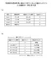
この実施例では、パケットスイッチ装置2に3個の無線アンテナ局(DUa1~DUa3)が接続されている。よって、パケットスイッチ装置2は、DUa1~DUa3と基地局(CU)との間の経路について、遅延時間をそれぞれ測定し、遅延マージン時間をそれぞれ算出する。各経路についての遅延時間および遅延マージン時間は、図8(a)に示す通りである。なお、以下の記載では、DUai(i=1~3)とCUとの間の経路を「経路DUai」と呼ぶことがある。 In this embodiment, the
また、パケットスイッチ装置2は、他のパケットスイッチ装置からMFHパケットを受信することがある。以下の記載では、DUxから他のパケットスイッチ装置を経由してCUに達する経路を「経路xSW」と呼ぶことがある。なお、パケットスイッチ装置2は、経路xSWの遅延時間および遅延マージン時間を有している必要はない。 Also, the
スケジューリング部11は、優先キュー設定部11a、キュー振分け部11b、優先キュー11c、転送タイミング制御部11dを備える。但し、スケジューリング部11は、図7に示していない他の機能を備えていてもよい。なお、優先キュー11cは、複数のキューバッファを含む。この実施例では、スケジューリング部11は、優先キュー0~4を備える。各優先キュー0~4は、受信MFHパケットを格納し得る。 The
優先キュー設定部11aは、MFHパケットを伝送する経路と優先キュー0~4との対応関係を表す振分けルールを作成する。そして、優先キュー設定部11aは、作成した振分けルールをキュー振分け部11bに与える。 The priority
ここで、MFHパケットを伝送する経路の遅延マージン時間と、その経路を介して伝送されるMFHパケットを格納すべき優先キューとの対応関係は、予め決められているものとする。例えば、図8(b)に示す振分けポリシにおいては、遅延マージン時間が9μ秒以下の経路を介して受信するMFHパケットは、優先キュー1に格納される。同様に、遅延マージン時間が10~29μ秒の経路を介して受信するMFHパケットは、優先キュー2に格納される。遅延マージン時間が30~59μ秒の経路を介して受信するMFHパケットは、優先キュー3に格納される。遅延マージン時間が60μ秒以上の経路を介して受信するMFHパケットは、優先キュー4に格納される。 Here, it is assumed that the correspondence relationship between the delay margin time of the route for transmitting the MFH packet and the priority queue in which the MFH packet transmitted via that route is to be stored is determined in advance. For example, according to the distribution policy shown in FIG. Similarly, MFH packets received via paths with delay margin times of 10 to 29 μs are stored in
そして、この振分けポリシに従って振分けルールが作成される。この実施例では、経路DUa1の遅延マージン時間は53μ秒なので、図8(a)に示すように、経路DUa1に対して優先キュー3が割り当てられる。同様に、経路DUa2の遅延マージン時間は76μ秒なので、経路DUa2に対して優先キュー4が割り当てられる。また、経路DUa3の遅延マージン時間は23μ秒なので、経路DUa3に対して優先キュー2が割り当てられる。 Then, a sorting rule is created according to this sorting policy. In this embodiment, the delay margin time of the route DUa1 is 53 μs, so
キュー振分け部11bは、優先キュー設定部11aから与えられる振分けルールに従って、受信MFHパケットを優先キュー0~4に格納する。ここで、各MFHパケットが通過する経路は、例えば、パケットヘッダに記録されているVLANIDにより識別されるものとする。なお、この実施例では、各DUとCUとの間のパスは、1つの仮想LANにより実現されるものとする。 The
したがって、キュー振分け部11bは、受信MFHパケットのVLANIDを参照することにより、各受信MFHパケットを対応する優先キューに格納する。この実施例では、図8(a)に示すように、経路DUa1を介して受信するMFHパケットは優先キュー3に格納される。また、経路DUa2を介して受信するMFHパケットは優先キュー4に格納され、経路DUa3を介して受信するMFHパケットは優先キュー2に格納される。なお、他のパケットスイッチ装置を経由して受信するMFHパケットは、優先キュー0に格納される。 Therefore, the
転送タイミング制御部11dは、予め決められた読出しポリシに従って、優先キュー0~4からMFHパケットを読み出す。優先キュー0~4から読み出されたMFHパケットは、TAS機能13を介してネットワークに出力される。ただし、TAS機能13は、MFHパケットに対してゲート制御を行わない。 The transfer
読出しポリシは、図8(b)に示すように、各優先キューの転送タイミングを表す。この例では、優先キュー1は、2μ秒間隔で読み出される。同様に、優先キュー2は10μ秒間隔で読み出され、優先キュー3は30μ秒間隔で読み出され、優先キュー4は60μ秒間隔で読み出される。優先キュー0の待ち時間はゼロである。なお、優先キュー2の読出し間隔は、優先キュー1の読出し間隔の整数倍であることが好ましい。同様に、優先キュー3の読出し間隔は、優先キュー2の読出し間隔の整数倍であることが好ましく、優先キュー4の読出し間隔は、優先キュー3の読出し間隔の整数倍であることが好ましい。 The read policy represents the transfer timing of each priority queue, as shown in FIG. 8(b). In this example,
TAS機能13は、図7に示すように、ゲート制御部13aおよびゲート13bを備える。ゲート制御部13aは、MFHパケットの転送に応じてゲート13bを制御する。例えば、スケジューリング部11によりMFHパケットが出力されるときは、ゲート制御部13aはゲート13bを閉じる。この場合、非MFHキュー12に格納されている非MFHパケットは、ゲート13bを通過することは出来ない。即ち、スケジューリング部11によりMFHパケットが出力されるときは、パケットスイッチ装置2は、非MFHパケットを出力しない。これにより、MFHパケットの優先制御が実現される。 The
このように、パケットスイッチ装置2は、読出し間隔の異なる複数の優先キュー1~4を備える。ここで、パケットスイッチ装置2は、エンド・エンド間の最大遅延時間を越えないように各MFHパケットを処理することが要求される。よって、遅延時間が大きい経路に対して高い優先度が与えられる。そして、遅延時間が大きい経路を介して受信するMFHパケットは、パケットスイッチ装置2内でのキュー待ち時間が長くならないように、読出し間隔が短い優先キューに格納される。図7~図8に示す例では、経路DUa3を介して受信するMFHパケットは、優先キュー2に格納される。なお、各優先キューの読出し間隔は、パケットスイッチ装置2内でのキュー待ち時間の最大値に相当する。 Thus, the
一方、遅延時間が短い経路を介して受信するMFHパケットは、遅延時間が長い経路を介して受信するMFHパケットと比べて、パケットスイッチ装置2内でのキュー待ち時間を長くできる。よって、遅延時間が短い経路を介して受信するMFHパケットは、読出し間隔が長い優先キューに格納される。図7~図8に示す例では、経路DUa2を介して受信するMFHパケットは、優先キュー4に格納される。 On the other hand, an MFH packet received via a route with a short delay time can have a longer queue waiting time in the
他のパケットスイッチ装置を経由して受信するMFHパケットは、他のパケットスイッチ装置において既にキュー待ち時間が発生している可能性がある。すなわち、他のパケットスイッチ装置を経由して受信するMFHパケットの遅延時間は、すでに最大遅延時間に近い状態となっている可能性がある。このため、パケットスイッチ装置2において、他のパケットスイッチ装置を経由して受信するMFHパケットは、キュー待ち時間がゼロである優先キュー0に格納される。すなわち、他のパケットスイッチ装置を経由して受信するMFHパケットは、最も優先度の高い優先キューに格納される。なお、読出し間隔が短い優先キューは、優先度の高い優先キューの一例であり、読出し間隔が長い優先キューは、優先度の低い優先キューの一例である。 MFH packets received via other packet switching devices may already experience queue waiting time in other packet switching devices. That is, there is a possibility that the delay time of the MFH packet received via another packet switch device is already close to the maximum delay time. Therefore, in the
そして、スケジューリング部11は、下記の読出しルールに従って優先キュー0~4からMFHパケットを読み出して出力する。 Then, the
(1)優先キュー0にMFHパケットが格納されているときは、スケジューリング部11は、即座に、そのMFHパケットを読み出す。この後、スケジューリング部11は、優先キュー1~4に格納されているMFHパケットを読み出す。このとき、優先キュー0~4に格納されているMFHパケットが連続して読み出されることが好ましい。 (1) When an MFH packet is stored in the
(2)優先キューi(i=1~4)の読出しタイミングにおいて、優先キューiにMFHパケットが格納されているときは、スケジューリング部11は、そのMFHパケットを読み出す。この後、スケジューリング部11は、優先キューiよりも優先度の低い各優先キューに格納されているMFHパケットを読み出す。例えば、優先キュー1の読出しタイミングにおいて優先キューからMFHパケットを読み出したときは、スケジューリング部11は、優先キュー2~4に格納されているMFHパケットを読み出す。このとき、優先キューi~4に格納されているMFHパケットが連続して読み出されることが好ましい。 (2) When an MFH packet is stored in the priority queue i (i=1 to 4) at the timing of reading the priority queue i, the
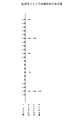
上述の読出しルールに従って優先キュー0~4からMFHパケットを読み出すことにより、パケットスイッチ装置2は、MFHパケットを可能な限り連続して出力することができる。ここで、MFHパケットが連続して出力されるときは、図5を参照して説明したように、連続するMFHパケット間にマージン期間Mを設ける必要はない。すなわち、TAS機能13において、マージン期間Mが削減される。よって、ゲート13bが閉じている期間が短くなり、非MFHパケットのための通信帯域が増加する。なお、優先キュー1~4の読出しタイミングは、図9に示すように、互いに同期していることが好ましい。この場合、優先キュー1~4に格納されているMFHパケットは、より連続して出力されやすくなる。なお、図9に示す「矢印」は、それぞれ読出しタイミングを表す。 By reading the MFH packets from the
加えて、パケットスイッチ装置2内での各MFHパケットのキュー待ち時間は、そのMFHパケットを伝送する経路の遅延時間と標準化等において規定されている最大遅延時間との差分より小さくなるように決定される。すなわち、各経路の遅延時間の余裕度に応じてキュー待ち時間が設定される。したがって、中継ネットワーク1は、MFHにおいて規定されている遅延条件を満足しながら、非MFHパケットのための通信帯域を増加させることができる。 In addition, the queue waiting time of each MFH packet in the
図10は、パケットスイッチ装置2の構成の一例を示す。パケットスイッチ装置2は、入出力IF31、スイッチ処理部32、パケット処理部33、保守端末IF41、CPU42、記憶装置43、メモリ44を備える。なお、パケットスイッチ装置2は、図10に示していない他の構成を備えていてもよい。 FIG. 10 shows an example of the configuration of the
入出力IF31は、中継ネットワーク1と接続するためのインタフェースを提供する。なお、入出力IF31は、光ファイバを接続するための入力ポートおよび出力ポートを備えていてもよい。また、入出力IF31は、レイヤ2の信号を終端する機能を備えていてもよい。 The input/output IF 31 provides an interface for connecting with the
スイッチ処理部32は、入出力IF31を介して受信するパケットを、宛先に対応するパケット処理部33に導く。一例としては、スイッチ処理部32は、受信パケットのヘッダに設定されているVLANID及び/又は宛先アドレスに基づいて、そのパケットを対応する出力ポートに接続されるパケット処理部33に導く。尚、スイッチ処理部32は、CUP42から与えられる指示および情報に基づいてスイッチ処理を実行する。 The
パケット処理部33は、CUP42から与えられる指示および情報に基づいて、MFHパケットの優先制御を実行する。したがって、パケット処理部33は、スケジューリング部11、非MFHキュー12、TAS機能13を含む。パケット処理部33の機能については後で詳しく説明する。 The
保守端末IF41は、保守端末100に接続するためのインタフェースを提供する。保守端末100は、ユーザまたはネットワーク管理者により使用される。そして、保守端末100は、パケットスイッチ装置2の設定に係わる指示および情報を生成する。保守端末100により生成される指示および情報は、保守端末IF41を介してCPU42に与えられる。 The maintenance terminal IF 41 provides an interface for connecting to the
CPU42は、記憶装置43に格納されているプログラムを実行することによりパケットスイッチ装置2の動作を制御する。このとき、CPU42は、保守端末100から与えられる指示および情報を利用してプログラムを実行してもよい。 The
記憶装置43は、不揮発メモリを含み、CPU42により実行されるプログラムを格納する。また、記憶装置43は、CPU42が使用する情報およびデータを保存する。尚、記憶装置43は、パケットスイッチ装置2の外部に設けられてもよい。メモリ44は、揮発メモリであり、CPU42の作業領域として使用される。 The
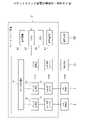
図11は、パケットスイッチ装置2の機能ブロック図である。パケットスイッチ装置2は、上述したように、入出力IF31、スイッチ処理部32、パケット処理部33を備える。そして、パケット処理部33は、図11に示すように、MFH/非MFH振分け部51、非MFHキュー12、TAS機能13、キュー振分け部11b、優先キュー11c、転送タイミング制御部11d、タイミング設定部52を備える。 FIG. 11 is a functional block diagram of the
上記構成のパケットスイッチ装置2にパケット(MFHパケット及び非MFHパケットを含む)が到着すると、入出力IF31は、そのパケットをスイッチ処理部32に導く。そうすると、スイッチ処理部32は、その受信パケットを、宛先に対応するパケット処理部33に導く。 When a packet (including MFH packets and non-MFH packets) arrives at the
MFH/非MFH振分け部51は、受信パケットがMFHパケットであるか否かを判定する。パケットの種別は、例えば、ヘッダ情報中のVLANIDにより識別される。MFHパケットは、キュー振分け部11bに導かれる。一方、非MFHパケットは、非MFHキュー12に格納される。非MFHキュー12は、バッファメモリであり、非MFHパケットを格納する。そして、TAS機能13のゲートが閉じているときは、非MFHキュー12は、非MFHパケットを保持する。 The MFH/
TAS機能13は、MFHパケットの受信タイミングに応じて、非MFHキュー12の出力側に設けられるゲートの開閉を制御する。パケットスイッチ装置2がMFHパケットを転送するときは、TAS機能13は、ゲートを閉じることで非MFHパケットの出力を停止する。 The
キュー振分け部11bは、受信MFHパケットを伝送する経路の優先度(又は、受信MFHパケットの送信元DUの優先度)に応じて、その受信MFHパケットを対応する優先キュー0~4に格納する。受信MFHパケットを伝送する経路または受信MFHパケットの送信元DUは、例えば、ヘッダ情報中のVLANIDにより識別される。たとえば、他のパケットスイッチ装置を経由して受信するMFHパケットは、優先キュー0に格納される。なお、受信MFHパケットを伝送する経路または受信MFHパケットの送信元DUと優先キュー0~4との対応関係を表す振分けルールは、優先キュー設定部11aから与えられる。 The
優先キュー11cは、複数の優先キューを備える。この実施例では、優先キュー11cは、5個の優先キュー0~4を含む。優先キュー0~4は、それぞれバッファメモリにより実現される。 The
転送タイミング制御部11dは、各優先キュー0~4に対して設定されている読出し間隔(または、読出しタイミング)に基づいて、優先キュー0~4からMFHパケットを読み出して出力する。なお、転送タイミング制御部11dは、ある優先度の優先キューからMFHパケットを読み出したときは、それよりも低い優先度の優先キューからもMFHパケットを読み出して出力する。すなわち、2以上の優先キューからMFHパケットが連続して読み出される。また、優先キュー0~4のうちのいずれかの優先キューが満杯状態となったときは、転送タイミング制御部11dは、指定された読出し間隔にかかわらず、その優先キューからMFHパケットを読み出す。この場合も、転送タイミング制御部11dは、満杯状態となった優先キューより低い優先度の優先キューからもMFHパケットを読み出して出力する。 The transfer
タイミング設定部52は、後述する優先キュー管理部65からの指示に応じて、転送タイミング制御部11dによる転送タイミングを変更することができる。 The
パケットスイッチ装置2は、上述したパケット処理部33を制御するためのソフトウェア処理部60を備える。ソフトウェア処理部60は、遅延時間管理部61、マージン算出部22、中継経路管理部63、優先キュー設定部11a、優先キュー管理部65、データベース66を備える。なお、遅延時間管理部61、マージン算出部22、中継経路管理部63、優先キュー設定部11a、優先キュー管理部65は、例えば、図10に示すCPU42が記憶装置43に格納されているソフトウェアプログラムを実行することにより実現される。 The
なお、以下の記載では、パケットスイッチ装置2に接続されるDUとCUとの間の経路を「MFH経路」と呼ぶことがある。また、他のパケットスイッチ装置を介してパケットスイッチ装置2に接続されるDUとCUとの間の経路を「中継経路」と呼ぶことがある。 In the following description, the route between the DU and CU connected to the
遅延時間管理部61は、自装置(即ち、パケットスイッチ装置2)が遅延マージン時間を設定すべき各MFH経路について、保守端末100から遅延時間の測定値を取得する。なお、遅延時間管理部61は、例えば、自装置に接続する各DUとCUとの間の経路について、それぞれ遅延マージン時間を設定する。また、遅延時間管理部61は、保守端末100から調整係数を取得する。遅延時間の測定値および調整係数は、データベース66に保存される。保守端末100から遅延時間の測定値および/または調整係数を取得できないときは、予め用意されているデフォルト値が使用される。 The delay
マージン算出部22は、データベース66に保存されている遅延時間の測定値および調整係数に基づいて、各経路について遅延マージン時間を算出する。遅延マージン時間は、例えば、下式で算出される。
遅延マージン時間=最大遅延時間-経路DUiの遅延時間-調整係数The
Delay margin time = maximum delay time - delay time of path DUi - adjustment factor
中継経路管理部63は、他のパケットスイッチ装置を経由して受信するMFHパケットを識別するための識別情報(例えば、VLANID)を保守端末100から取得する。この識別情報は、実質的に、中継経路を識別する。そして、中継経路管理部63は、この識別情報を優先キュー0に対応づけてもよい。なお、保守端末100から取得した識別情報は、データベース66に保存される。 The relay
優先キュー設定部11aは、各MFH経路についてマージン算出部22により算出された遅延マージン時間に基づいて、各MFH経路と優先キュー1~4との対応関係を表す振分けルールを作成する。各MFH経路は、たとえば、VLANIDにより識別される。また、振分けルールにおいては、他のパケットスイッチ装置を経由して受信するMFHパケットは、優先キュー0に対応づけられる。なお、図8(a)は、振分けルールの一例を示す。そして、作成した振分けルールは、キュー振分け部11bに与えられる。 Based on the delay margin time calculated by the
優先キュー管理部65は、保守端末100から与えられる指示に基づいて、各優先キューの転送タイミングに係わる情報を設定する。例えば、図8(b)に示す遅延マージン時間の範囲および転送タイミング(或いは、読出し間隔)を表す情報が保守端末100から与えられる。これらの情報は、データベース66に保存される。転送タイミングに係わる情報を保守端末100から取得できないときは、予め用意されているデフォルト値が使用される。 The priority
尚、ソフトウェア処理部60は、複数のパケット処理部33を制御してもよい。また、図7に示すスケジューリング部11は、ソフトウェアおよびハードウェア回路により実現してもよい。例えば、優先キュー設定部11aは、ソフトウェアで実現してもよい。 Note that the
<フローチャート>
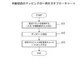
図12は、優先キューのマッピングの一例を示すフローチャートである。このフローチャートの処理は、パケットスイッチ装置2が動作を開始する前の初期設定において実行される。以下では、図11の機能ブロック図の構成を用いて説明する。<Flowchart>
FIG. 12 is a flowchart illustrating an example of priority queue mapping. The processing of this flowchart is executed in the initial setting before the
S1において、遅延時間管理部61は、保守端末100から設定コマンドを取得する。この設定コマンドは、MFHパケットを伝送する経路毎に、VLANIDと遅延時間の測定値との対応関係を含む。そして、遅延時間管理部61は、S2において、この設定コマンドをデータベース66に保存する。 In S<b>1 , the delay
S3において、マージン算出部22は、各経路の遅延マージン時間を算出する。遅延マージンは、最大遅延時間と遅延時間の測定値との差分に依存する。S4において、優先キュー設定部11aは、遅延マージン時間に基づいて、各経路に対応する優先キュー1~4を特定する。このとき、優先キュー設定部11aは、例えば、図8(b)に示す振分けポリシに基づいて各経路に対応する優先キュー1~4を特定する。例えば、ある経路の遅延マージン時間が40μ秒であれば、その経路に対して優先キュー3が特定される。経路と優先キューとの対応関係を表す振分けルールは、優先キュー設定部11aからキュー振分け部11bに与えられる。 In S3, the
S5において、キュー振分け部11bは、振分けルールに従って、各経路を識別するVLANIDを優先キュー1~4にマッピングする。図8(a)に示す例では、例えば、経路DUa1が優先キュー3にマッピングされ、経路DUa2が優先キュー4にマッピングされている。「マッピング」は、指定されたVLANIDが付与されたMFHパケットが対応する優先キューに導かれるように、ハードウェア回路を設定することで実現される。 In S5, the
図13は、中継経路のマッピングの一例を示すフローチャートである。このフローチャートの処理は、パケットスイッチ装置2が動作を開始する前の初期設定において実行される。なお、中継経路は、他のパケットスイッチ装置を経由して受信するMFHパケットが伝送される経路を表す。以下では、図11の機能ブロック図の構成を用いて説明する。 FIG. 13 is a flowchart illustrating an example of relay path mapping. The processing of this flowchart is executed in the initial setting before the
S11において、中継経路管理部63は、保守端末100から設定コマンドを取得する。この設定コマンドは、中継経路毎のVLANIDを表す情報を含む。そして、中継経路管理部63は、S12において、この設定コマンドをデータベース66に保存する。そして、S13において、キュー振分け部11b(または、中継経路管理部63)は、各中継経路を識別するVLANIDを優先キュー0にマッピングする。 In S<b>11 , the relay
図14は、調整係数を変更する処理の一例を示すフローチャートである。このフローチャートの処理は、調整係数を変更する指示が保守端末100からパケットスイッチ装置2に与えられたときに実行される。以下では、図11の機能ブロック図の構成を用いて説明する。 FIG. 14 is a flowchart illustrating an example of processing for changing adjustment coefficients. The processing of this flowchart is executed when an instruction to change the adjustment coefficient is given from the
S21において、遅延時間管理部61は、保守端末100から設定コマンドを取得する。この設定コマンドは、新たな調整係数を表す情報を含む。そして、遅延時間管理部61は、S22において、この設定コマンドをデータベース66に保存する。 In S<b>21 , the delay
S23~S27は、各MFH経路に対して実行される。すなわち、パケットスイッチ装置2は、新たな調整係数が与えられると、MFH経路を1つずつ順番に選択してS23~S26の処理を実行する。 S23-S27 are executed for each MFH path. That is, when the
S23において、マージン算出部22は、新たな調整係数を使用して、選択された経路の遅延マージン時間を算出する。S24において、優先キュー設定部11aは、新たに算出した遅延マージン時間に基づいて、選択された経路に対応する優先キュー1~4を特定する。S25において、新たに特定された優先キューが現在の優先キューと同じか否かを判定する。そして、新たに特定された優先キューが現在の優先キューと異なるときは、キュー振分け部11bは、S26において、選択された経路を識別するVLANIDを、新たに特定された優先キューにマッピングする。 In S23, the
図15は、転送タイミングを変更する処理の一例を示すフローチャートである。このフローチャートの処理は、転送タイミングを変更する指示が保守端末100からパケットスイッチ装置2に与えられたときに実行される。 FIG. 15 is a flowchart illustrating an example of processing for changing transfer timing. The processing of this flowchart is executed when an instruction to change the transfer timing is given from the
S31において、優先キュー管理部65は、保守端末100から設定コマンドを取得する。この設定コマンドは、新たな転送タイミングを表す情報を含む。この実施例では、転送タイミングは、優先キューの読出し間隔で表される。すなわち、この設定コマンドは、各優先キュー1~4の読出し間隔を表す情報を含む。そして、優先キュー管理部65は、S32において、この設定コマンドをデータベース66に保存する。 In S<b>31 , the priority
S33において、優先キュー管理部65は、各優先キュー1~4に対応する遅延マージン範囲を更新する。すなわち、図8(a)に示す振分けポリシが更新される。この実施例では、各優先キュー1~4に対応する遅延マージン範囲は、下記のように表される。ここでは、優先キュー1、2、3、4の読出し間隔がそれぞれP1、P2、P3、P4で表されるものとする。
優先キュー1:「P2」以下
優先キュー2:「P2」~「P3-1」
優先キュー3:「P3」~「P4-1」
優先キュー4:「P4」以上In S33, the
Priority queue 1: "P2" and below Priority queue 2: "P2" to "P3-1"
Priority queue 3: "P3" to "P4-1"
Priority queue 4: "P4" or higher
S34~S36は、各MFH経路に対して実行される。すなわち、パケットスイッチ装置2は、新たな転送タイミングが与えられると、MFH経路を1つずつ順番に選択してS34~S35の処理を実行する。 S34-S36 are performed for each MFH path. That is, when a new transfer timing is given, the
S34において、優先キュー管理部65は、選択されたMFH経路の遅延マージン時間がどの遅延マージン範囲に属するのかを特定する。続いて、新たに特定された遅延マージン範囲に対応する優先キューが現在の優先キューと同じか否かを判定する。そして、新たに特定された優先キューが現在の優先キューと異なるときは、キュー振分け部11bは、S35において、選択された経路を識別するVLANIDを、新たに特定された優先キューにマッピングする。 In S34, the priority
S37において、転送タイミング制御部11bは、優先キュー11c(すなわち、優先キュー0~4)に格納されているMFHパケットをすべて読み出して出力する。S38~S39において、タイミング設定部52は、各優先キュー1~4の転送タイミング(すなわち、読出しタイミング)を再設定する。このとき、優先キュー1~4の転送タイミングは、図9に示すように、互いに同期するように再設定される。また、転送タイミングをカウントするためのタイマが再設定される。 In S37, the transfer
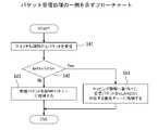
図16は、パケット受信処理の一例を示すフローチャートである。このフローチャートの処理は、パケットスイッチ装置2にパケットが到着したときに実行される。 FIG. 16 is a flowchart illustrating an example of packet reception processing. The processing of this flowchart is executed when a packet arrives at the
S41において、パケット処理部33は、スイッチ処理部32を介してパケットを受信する。S42において、MFH/非MFH振分け部51は、受信パケットのヘッダ情報に基づいて、受信パケットがMFHパケットであるか否かを判定する。受信パケットがMFHパケットであるか否かは、この実施例では、その受信パケットに付与されているVLANIDにより判定される。 In S<b>41 , the
受信パケットがMFHパケットでないときは、その受信パケットは、S43において、非MFHキュー12に格納される。一方、受信パケットがMFHパケットであるときは、その受信パケットは、キュー振分け部11bに導かれる。そして、S44において、キュー振分け部11bは、受信パケットのヘッダ情報に基づいて、そのパケットのMFH経路を特定する。MFHパケットを伝送するMFH経路は、この実施例では、VLANIDにより判定される。そして、キュー振分け部11bは、マッピング情報に基づいて、受信パケットをVLANIDに対応する優先キューに格納する。マッピング情報は、図12および図13に示すフローチャートの処理により作成されている。 If the received packet is not an MFH packet, the received packet is stored in the
このように、受信パケットがMFHパケットでないときは、そのパケットは、非MFHキュー12に格納される。一方、受信パケットがMFHパケットであるときは、そのパケットは、MFH経路に対応する優先キュー0~4に格納される。 Thus, when a received packet is not an MFH packet, the packet is stored in
図17は、パケット転送処理の一例を示すフローチャートである。このフローチャートの処理は、MFHパケットが他のパケットスイッチ装置を経由してパケットスイッチ装置2に到着したときに実行される。なお、他のパケットスイッチ装置を経由してパケットスイッチ装置2に到着したMFHパケットは、キュー振分け部11bにより優先キュー0に格納される。 FIG. 17 is a flowchart illustrating an example of packet transfer processing. The processing of this flowchart is executed when an MFH packet arrives at the
S51において、転送タイミング制御部11dは、優先キュー0のパケットキューイングを検出する。即ち、転送タイミング制御部11dは、優先キュー0にパケットが格納されたことを検出する。そうすると、転送タイミング制御部11dは、S52において、優先キュー0に格納されているすべてのパケットを読み出して出力する。すなわち、パケットスイッチ装置2に到着したMFHパケットは、いったん優先キュー0に格納された後、即座に読み出されて出力される。 In S51, the transfer
S53~S56は、優先キュー0以外の各優先キュー1~4に対してそれぞれ実行される。すなわち、S53において、転送タイミング制御部11dは、優先キュー1~4のうちの1つを選択する。S54において、選択した優先キューにパケットが格納されているか否かを検出する。そして、選択した優先キューにパケットが格納されているときは、転送タイミング制御部11dは、S55において、選択した優先キューに格納されているすべてのパケットを読み出して出力する。 S53-S56 are executed for each of priority queues 1-4 other than
このように、他のパケットスイッチ装置を経由してMFHパケットがパケットスイッチ装置2に到着すると、そのMFHパケットは即座に転送される。続いて、優先キュー1~4に格納されているMFHパケットも連続して転送される。 Thus, when an MFH packet arrives at the
図18は、パケット転送処理の他の例を示すフローチャートである。このフローチャートの処理は、優先キュー1~4のいずれかにおいて転送タイミングが検知されたときに実行される。なお、各優先キュー1~4の転送タイミングは、タイミング設定部52により予め設定されているものとする。また、転送タイミングは、例えば、不図示のタイマにより検知される。 FIG. 18 is a flowchart illustrating another example of packet transfer processing. The processing of this flowchart is executed when the transfer timing is detected in any of the priority queues 1-4. It is assumed that the transfer timings of the
S61において、転送タイミング制御部11dは、転送タイミングが検知された優先キューを特定する。以下の記載では、転送タイミングが検知された優先キューを優先キューXと呼ぶことがある。S62において、転送タイミング制御部11dは、優先キューXに格納されているすべてのパケットを読み出して出力する。 In S61, the transfer
S63~S66の処理は、図17に示すS53~S56と実質的に同じである。但し、S63~S66の処理は、優先キューXよりも読出し間隔の長い各優先キューに対して実行される。すなわち、優先キューXよりも読出し間隔の長い各優先キューに格納されているMFHパケットが出力される。 The processing of S63-S66 is substantially the same as that of S53-S56 shown in FIG. However, the processing of S63 to S66 is executed for each priority queue having a longer read interval than the priority queue X. That is, the MFH packets stored in each priority queue having a longer read interval than the priority queue X are output.
このように、いずれかの優先キューの転送タイミングが検知されると、その優先キューに格納されているMFHパケットが転送される。続いて、他の優先キューに格納されているMFHパケットも連続して転送される。 In this way, when the transfer timing of any priority queue is detected, the MFH packets stored in that priority queue are transferred. Subsequently, MFH packets stored in other priority queues are also transferred continuously.
なお、各優先キュー1~4の転送タイミングが図9に示すように互いに同期しているときには、優先キュー2~4の転送タイミングは、優先キュー1の転送タイミングに含まれる。よって、この場合、優先キュー1の転送タイミングが発生する毎に、図18に示すフローチャートの処理が実行されることになる。 When the transfer timings of priority queues 1-4 are synchronized with each other as shown in FIG. 9, the transfer timings of priority queues 2-4 are included in the transfer timing of
1 中継ネットワーク
2 パケットスイッチ装置
3 無線アンテナ局(DUまたはRRH)
4 基地局装置(CUまたはBBU)
11 スケジューリング部
11a 優先キュー設定部
11b キュー振分け部
11c 優先キュー(0~4)
11d 転送タイミング制御部
12 非MFHキュー
13 TAS機能
13a ゲート制御部
13b ゲート
21 遅延時間測定部
22 マージン算出部
33 パケット処理部
42 CPU
51 MFH/非MFH振分け部
52 タイミング設定部1
4 Base station equipment (CU or BBU)
11
11d transfer
51 MFH/
Claims (6)
Translated fromJapanese非優先パケットを格納する非優先パケット格納部と、
前記非優先パケット格納部の出力側に設けられるゲートと、
優先パケットを格納する複数の優先パケット格納部と、
前記パケット処理装置が優先パケットを受信したときに、前記受信優先パケットを、前記受信優先パケットが伝送される経路の送信元と宛先との間の遅延時間に対応する優先パケット格納部に格納する振分け部と、
各優先パケット格納部に対して異なる読出し間隔を設定するタイミング設定部と、
前記タイミング設定部により設定される読出し間隔に従って前記複数の優先パケット格納部から優先パケットを読み出して出力する転送タイミング制御部と、
前記転送タイミング制御部により優先パケットが出力されるタイミングに応じて前記ゲートを制御するゲート制御部と、を備え、
前記転送タイミング制御部は、前記複数の優先パケット格納部の中の1つの優先パケット格納部から優先パケットを読み出して出力するときに、他の優先パケット格納部からも優先パケットを読み出して出力する
ことを特徴とするパケット処理装置。A packet processing device for processing a priority packet and a non-priority packet in a network that transmits a priority packet and a non-priority packet having a lower priority than the priority packet,
a non-priority packet storage unit for storing non-priority packets;
a gate provided on the output side of the non-prioritized packet storage unit;
a plurality of priority packet storage units for storing priority packets;
Distributing, when the packet processing device receives a priority packet, storing the reception priority packet in a priority packet storage section corresponding to a delay time between a source and a destination of a route along which the reception priority packet is transmitted. Department and
a timing setting unit that sets a different readout interval for each priority packet storage unit;
a transfer timing control unit that reads and outputs priority packets from the plurality of priority packet storage units according to the read interval set by the timing setting unit;
a gate control unit that controls the gate according to the timing at which the priority packet is output by the transfer timing control unit;
When reading and outputting priority packets from one priority packet storage section among the plurality of priority packet storage sections, the transfer timing control section also reads and outputs priority packets from other priority packet storage sections. A packet processing device characterized by:
前記振分け部は、優先パケットが伝送される経路の遅延マージン時間に基づいて優先パケットを対応する優先パケット格納部に格納する
ことを特徴とする請求項1に記載のパケット処理装置。further comprising a margin calculation unit for calculating the delay margin time of each route based on the difference between the maximum delay time of the priority packet and the delay time of each route;
2. The packet processing device according to claim 1, wherein the sorting unit stores the priority packet in the corresponding priority packet storage unit based on the delay margin time of the route through which the priority packet is transmitted.
ことを特徴とする請求項2に記載のパケット処理装置。3. The packet processing device according to claim 2, wherein the shorter the delay margin time corresponding to the priority packet storage section, the shorter the read interval set for the priority packet storage section.
前記転送タイミング制御部は、前記予め指定された優先パケット格納部に優先パケットが格納されると、即座に、前記予め指定された優先パケット格納部から優先パケットを読み出して出力する
ことを特徴とする請求項1に記載のパケット処理装置。when the packet processing device receives a priority packet via another packet processing device, the distribution unit stores the priority packet in a predesignated priority packet storage unit;
The transfer timing control unit is characterized in that, when a priority packet is stored in the predesignated priority packet storage unit, the transfer timing control unit immediately reads the priority packet from the predesignated priority packet storage unit and outputs the read priority packet. The packet processing device according to claim 1.
ことを特徴とする請求項4に記載のパケット処理装置。5. The transfer timing control unit reads and outputs priority packets from other priority packet storage units when reading and outputting the priority packets from the predetermined priority packet storage unit. The packet processing device according to .
前記ネットワークシステム内に実装される各パケット処理装置は、
非優先パケットを格納する非優先パケット格納部と、
前記非優先パケット格納部の出力側に設けられるゲートと、
優先パケットを格納する複数の優先パケット格納部と、
前記パケット処理装置が優先パケットを受信したときに、前記受信優先パケットを、前記受信優先パケットが伝送される経路の送信元と宛先との間の遅延時間に対応する優先パケット格納部に格納する振分け部と、
各優先パケット格納部に対して異なる読出し間隔を設定するタイミング設定部と、
前記タイミング設定部により設定される読出し間隔に従って前記複数の優先パケット格納部から優先パケットを読み出して出力する転送タイミング制御部と、
前記転送タイミング制御部により優先パケットが出力されるタイミングに応じて前記ゲートを制御するゲート制御部と、を備え、
前記転送タイミング制御部は、前記複数の優先パケット格納部の中の1つの優先パケット格納部から優先パケットを読み出して出力するときに、他の優先パケット格納部からも優先パケットを読み出して出力する
ことを特徴とするネットワークシステム。A network system that transmits a priority packet and a non-priority packet having a lower priority than the priority packet,
Each packetprocessing device implemented in the network system,
a non-priority packet storage unit for storing non-priority packets;
a gate provided on the output side of the non-prioritized packet storage unit;
a plurality of priority packet storage units for storing priority packets;
Distributing, when the packet processing device receives a priority packet, storing the reception priority packet in a priority packet storage section corresponding to a delay time between a source and a destination of a route along which the reception priority packet is transmitted. Department and
a timing setting unit that sets a different readout interval for each priority packet storage unit;
a transfer timing control unit that reads and outputs priority packets from the plurality of priority packet storage units according to the read interval set by the timing setting unit;
a gate control unit that controls the gate according to the timing at which the priority packet is output by the transfer timing control unit;
When reading and outputting priority packets from one priority packet storage section among the plurality of priority packet storage sections, the transfer timing control section also reads and outputs priority packets from other priority packet storage sections. A network system characterized by
Priority Applications (2)
| Application Number | Priority Date | Filing Date | Title |
|---|---|---|---|
| JP2019098260AJP7207165B2 (en) | 2019-05-27 | 2019-05-27 | Packet processor and network system |
| US16/847,234US11159426B2 (en) | 2019-05-27 | 2020-04-13 | Packet processing device and network system |
Applications Claiming Priority (1)
| Application Number | Priority Date | Filing Date | Title |
|---|---|---|---|
| JP2019098260AJP7207165B2 (en) | 2019-05-27 | 2019-05-27 | Packet processor and network system |
Publications (2)
| Publication Number | Publication Date |
|---|---|
| JP2020195020A JP2020195020A (en) | 2020-12-03 |
| JP7207165B2true JP7207165B2 (en) | 2023-01-18 |
Family
ID=73546521
Family Applications (1)
| Application Number | Title | Priority Date | Filing Date |
|---|---|---|---|
| JP2019098260AActiveJP7207165B2 (en) | 2019-05-27 | 2019-05-27 | Packet processor and network system |
Country Status (2)
| Country | Link |
|---|---|
| US (1) | US11159426B2 (en) |
| JP (1) | JP7207165B2 (en) |
Families Citing this family (4)
| Publication number | Priority date | Publication date | Assignee | Title |
|---|---|---|---|---|
| EP4252395A2 (en)* | 2020-12-16 | 2023-10-04 | Huawei Technologies Co., Ltd. | Cyclic queuing and forwarding (cqf) segmentation |
| WO2022264194A1 (en)* | 2021-06-14 | 2022-12-22 | 日本電信電話株式会社 | Signal forwarding device, signal forwarding method, signal forwarding system, and program |
| JP7582479B2 (en) | 2021-07-19 | 2024-11-13 | 日本電信電話株式会社 | Signal transfer control device, signal transfer control method, signal transfer control program, and signal transfer system |
| US20240372812A1 (en) | 2021-07-19 | 2024-11-07 | Nippon Telegraph And Telephone Corporation | Signal transfer control device, signal transfer control method, signal transfer control program, and signal transfer system |
Citations (5)
| Publication number | Priority date | Publication date | Assignee | Title |
|---|---|---|---|---|
| JP2006050360A (en) | 2004-08-06 | 2006-02-16 | Yokogawa Electric Corp | Communication apparatus |
| US20120213075A1 (en) | 2011-02-18 | 2012-08-23 | Alaxala Networks Corporation | Packet transfer device and power supply control method for qos control circuit |
| CN103262452A (en) | 2011-07-15 | 2013-08-21 | 三菱电机株式会社 | Transmission apparatus, reception apparatus, communication apparatus, communication system, and transmission method |
| JP2015207814A (en) | 2014-04-17 | 2015-11-19 | 株式会社デンソー | Gateway device and frame data relay control method |
| JP2018125597A (en) | 2017-01-30 | 2018-08-09 | 富士通株式会社 | Packet processing device and packet processing method |
Family Cites Families (14)
| Publication number | Priority date | Publication date | Assignee | Title |
|---|---|---|---|---|
| US5121383A (en)* | 1990-11-16 | 1992-06-09 | Bell Communications Research, Inc. | Duration limited statistical multiplexing in packet networks |
| US5859835A (en)* | 1996-04-15 | 1999-01-12 | The Regents Of The University Of California | Traffic scheduling system and method for packet-switched networks |
| JP2001144709A (en) | 1999-11-18 | 2001-05-25 | Sony Corp | Device and method for transmission and recording medium |
| JP2002164916A (en)* | 2000-11-22 | 2002-06-07 | Fujitsu Ltd | Relay device |
| JP2003338837A (en)* | 2002-05-22 | 2003-11-28 | Fujitsu Ltd | Communication quality assurance method in packet communication system and packet communication device with transfer delay assurance function |
| US7535900B2 (en)* | 2003-01-21 | 2009-05-19 | Symmetricom, Inc. | Multiple transmission bandwidth streams with defferentiated quality of service |
| US7792118B2 (en)* | 2003-06-19 | 2010-09-07 | Polytechnic University | Switch module memory structure and per-destination queue flow control for use in a switch |
| JP4335619B2 (en)* | 2003-09-04 | 2009-09-30 | 株式会社エヌ・ティ・ティ・ドコモ | Packet priority control apparatus and method |
| US7936770B1 (en)* | 2005-03-08 | 2011-05-03 | Enterasys Networks, Inc. | Method and apparatus of virtual class of service and logical queue representation through network traffic distribution over multiple port interfaces |
| JP4851362B2 (en) | 2006-04-12 | 2012-01-11 | 三菱電機株式会社 | Ring network system |
| US7826469B1 (en)* | 2009-03-09 | 2010-11-02 | Juniper Networks, Inc. | Memory utilization in a priority queuing system of a network device |
| US20110090805A1 (en)* | 2009-10-21 | 2011-04-21 | Hong Kong Applied Science And Technology Research Institute Co., Ltd. | Systems and methods providing a decoupled quality of service architecture for communications |
| WO2015129167A1 (en) | 2014-02-26 | 2015-09-03 | 三菱電機株式会社 | Light transport system and delay measurement method |
| JP6867240B2 (en) | 2017-06-16 | 2021-04-28 | 日本電信電話株式会社 | Communication device and frame transfer method |
- 2019
- 2019-05-27JPJP2019098260Apatent/JP7207165B2/enactiveActive
- 2020
- 2020-04-13USUS16/847,234patent/US11159426B2/enactiveActive
Patent Citations (5)
| Publication number | Priority date | Publication date | Assignee | Title |
|---|---|---|---|---|
| JP2006050360A (en) | 2004-08-06 | 2006-02-16 | Yokogawa Electric Corp | Communication apparatus |
| US20120213075A1 (en) | 2011-02-18 | 2012-08-23 | Alaxala Networks Corporation | Packet transfer device and power supply control method for qos control circuit |
| CN103262452A (en) | 2011-07-15 | 2013-08-21 | 三菱电机株式会社 | Transmission apparatus, reception apparatus, communication apparatus, communication system, and transmission method |
| JP2015207814A (en) | 2014-04-17 | 2015-11-19 | 株式会社デンソー | Gateway device and frame data relay control method |
| JP2018125597A (en) | 2017-01-30 | 2018-08-09 | 富士通株式会社 | Packet processing device and packet processing method |
Also Published As
| Publication number | Publication date |
|---|---|
| US11159426B2 (en) | 2021-10-26 |
| JP2020195020A (en) | 2020-12-03 |
| US20200382422A1 (en) | 2020-12-03 |
Similar Documents
| Publication | Publication Date | Title |
|---|---|---|
| JP7207165B2 (en) | Packet processor and network system | |
| CN110024339B (en) | Packet forwarding method, forwarding device and network device | |
| US20190014053A1 (en) | Network Flow Control Method And Network Device | |
| US8213454B2 (en) | Self-adapting mechanism for managing data streams in a multiple access shared network | |
| US8787163B1 (en) | Method and apparatus for adjusting the size of a buffer in a network node based on latency | |
| WO2021147368A1 (en) | Method and apparatus for adjusting service level, device, system and storage medium | |
| WO2021057447A1 (en) | Method for determining required bandwidth for data stream transmission, and devices and system | |
| US11463370B2 (en) | Scalable deterministic services in packet networks | |
| US10361962B2 (en) | Packet processing technique for a communication network | |
| US11303578B2 (en) | Packet processing device and network system | |
| EP3395023B1 (en) | Dynamically optimized queue in data routing | |
| US12028265B2 (en) | Software-defined guaranteed-latency networking | |
| US20250133033A1 (en) | Message scheduling method, network device, storage medium, and computer program product | |
| CN117597908A (en) | Deterministic stream transmission method, system and electronic device | |
| WO2022237415A1 (en) | Packet forwarding method and related apparatus | |
| KR100772189B1 (en) | Method for transferring data frame end-to-end using virtual synchronization on local area network and Network Devices appling the same | |
| US20090147765A1 (en) | Air-time fair transmission regulation without explicit traffic specifications for wireless networks | |
| CN112751776A (en) | Congestion control method and related device | |
| JP7193787B2 (en) | Communication system, bridge device, communication method, and program | |
| CN117714368A (en) | A deterministic delay routing scheduling method and system based on segment routing | |
| KR101681613B1 (en) | Apparatus and method for scheduling resources in distributed parallel data transmission system | |
| JP7351405B2 (en) | Signal transfer system, signal transfer device, signal transfer management device, signal transfer method, and signal transfer program | |
| WO2022259540A1 (en) | Signal transferring device, signal transfer method, and program | |
| US20240080263A1 (en) | Packet processing apparatus and communication system | |
| JP7698223B2 (en) | Signal transfer system, signal transfer control device, signal transfer control method and program |
Legal Events
| Date | Code | Title | Description |
|---|---|---|---|
| A521 | Request for written amendment filed | Free format text:JAPANESE INTERMEDIATE CODE: A523 Effective date:20200608 | |
| A621 | Written request for application examination | Free format text:JAPANESE INTERMEDIATE CODE: A621 Effective date:20220208 | |
| A977 | Report on retrieval | Free format text:JAPANESE INTERMEDIATE CODE: A971007 Effective date:20221124 | |
| TRDD | Decision of grant or rejection written | ||
| A01 | Written decision to grant a patent or to grant a registration (utility model) | Free format text:JAPANESE INTERMEDIATE CODE: A01 Effective date:20221206 | |
| A61 | First payment of annual fees (during grant procedure) | Free format text:JAPANESE INTERMEDIATE CODE: A61 Effective date:20221219 | |
| R150 | Certificate of patent or registration of utility model | Ref document number:7207165 Country of ref document:JP Free format text:JAPANESE INTERMEDIATE CODE: R150 | |
| S111 | Request for change of ownership or part of ownership | Free format text:JAPANESE INTERMEDIATE CODE: R313111 |