JP7204722B2 - Combined toy, control subject toy body and companion toy - Google Patents
Combined toy, control subject toy body and companion toyDownload PDFInfo
- Publication number
- JP7204722B2 JP7204722B2JP2020198898AJP2020198898AJP7204722B2JP 7204722 B2JP7204722 B2JP 7204722B2JP 2020198898 AJP2020198898 AJP 2020198898AJP 2020198898 AJP2020198898 AJP 2020198898AJP 7204722 B2JP7204722 B2JP 7204722B2
- Authority
- JP
- Japan
- Prior art keywords
- control
- toy
- combination
- toy body
- detection unit
- Prior art date
- Legal status (The legal status is an assumption and is not a legal conclusion. Google has not performed a legal analysis and makes no representation as to the accuracy of the status listed.)
- Active
Links
Images


Classifications
- A—HUMAN NECESSITIES
- A63—SPORTS; GAMES; AMUSEMENTS
- A63H—TOYS, e.g. TOPS, DOLLS, HOOPS OR BUILDING BLOCKS
- A63H3/00—Dolls
- A63H3/16—Dolls made of parts that can be put together
- A—HUMAN NECESSITIES
- A63—SPORTS; GAMES; AMUSEMENTS
- A63H—TOYS, e.g. TOPS, DOLLS, HOOPS OR BUILDING BLOCKS
- A63H13/00—Toy figures with self-moving parts, with or without movement of the toy as a whole
- A—HUMAN NECESSITIES
- A63—SPORTS; GAMES; AMUSEMENTS
- A63H—TOYS, e.g. TOPS, DOLLS, HOOPS OR BUILDING BLOCKS
- A63H17/00—Toy vehicles, e.g. with self-drive; ; Cranes, winches or the like; Accessories therefor
- A—HUMAN NECESSITIES
- A63—SPORTS; GAMES; AMUSEMENTS
- A63H—TOYS, e.g. TOPS, DOLLS, HOOPS OR BUILDING BLOCKS
- A63H29/00—Drive mechanisms for toys in general
- A63H29/22—Electric drives
- A—HUMAN NECESSITIES
- A63—SPORTS; GAMES; AMUSEMENTS
- A63H—TOYS, e.g. TOPS, DOLLS, HOOPS OR BUILDING BLOCKS
- A63H3/00—Dolls
- A63H3/04—Dolls with deformable framework
- A—HUMAN NECESSITIES
- A63—SPORTS; GAMES; AMUSEMENTS
- A63H—TOYS, e.g. TOPS, DOLLS, HOOPS OR BUILDING BLOCKS
- A63H3/00—Dolls
- A63H3/28—Arrangements of sound-producing means in dolls; Means in dolls for producing sounds
- A—HUMAN NECESSITIES
- A63—SPORTS; GAMES; AMUSEMENTS
- A63H—TOYS, e.g. TOPS, DOLLS, HOOPS OR BUILDING BLOCKS
- A63H3/00—Dolls
- A63H3/36—Details; Accessories
- A—HUMAN NECESSITIES
- A63—SPORTS; GAMES; AMUSEMENTS
- A63H—TOYS, e.g. TOPS, DOLLS, HOOPS OR BUILDING BLOCKS
- A63H3/00—Dolls
- A63H3/36—Details; Accessories
- A63H3/46—Connections for limbs
- A—HUMAN NECESSITIES
- A63—SPORTS; GAMES; AMUSEMENTS
- A63H—TOYS, e.g. TOPS, DOLLS, HOOPS OR BUILDING BLOCKS
- A63H5/00—Musical or noise- producing devices for additional toy effects other than acoustical
Landscapes
- Physics & Mathematics (AREA)
- Engineering & Computer Science (AREA)
- Acoustics & Sound (AREA)
- Multimedia (AREA)
- Toys (AREA)
Description
Translated fromJapanese本発明は、複数の玩具を変形前形態から合体用形態に変形して合体させて遊ぶ合体玩具等に関する。 TECHNICAL FIELD The present invention relates to a united toy or the like that is played by transforming a plurality of toys from a pre-deformation form into a uniting form and uniting them.
男児に人気の玩具に合体玩具がある。合体玩具は、それぞれが1つの玩具として遊べる複数の玩具を、変形前形態から合体用形態へ変形させて結合させ、1つの大型玩具として遊ぶことができる玩具である。 Among toys that are popular among boys, there is a combination toy. A united toy is a toy that can be played as one large-sized toy by combining a plurality of toys that can be played as one toy by transforming them from a pre-deformation form to a united form.
合体玩具のうち特に人気なのは、特撮ヒーロー番組内にヒーロー達の搭乗機として登場する合体ロボットを模した玩具である。典型的な特撮ヒーロー番組の合体シーンでは、勇ましいBGMとともにヒーロー達が搭乗する複数の小型機(例えば、乗り物や、動物型のロボットの姿をしている機械)が次々に変形しながら合体し、最終的には巨大なロボットとなる。ヒーロー達は、その巨大ロボットを操縦して、敵の大怪獣やロボットと戦いこれに勝利する。子供は、その巨大ロボットを模した合体玩具で、あたかも自分が番組内のヒーローになった気分で、玩具を変形及び合体させて「ごっこ遊び」をする。 Among the combined toys, the ones that are particularly popular are the ones that imitate the combined robots that appear in special effects hero programs as machines for the heroes to board. In a typical combination scene of a tokusatsu hero program, multiple small machines (for example, vehicles or machines in the shape of animal robots) piloted by heroes are combined while transforming one after another with brave BGM. It ends up being a giant robot. Heroes pilot the giant robots to fight and defeat enemy giant monsters and robots. Children play "pretend play" by transforming and combining the toys with the united toy that imitates the giant robot as if they were the hero of the program.
従来の合体玩具の中には、効果音(例えば、BGM、機械同士が接触して結合するエフェクト音、ヒーロー達の掛け声、など)を放音させる音源を内蔵し、ユーザが所定のボタンを操作することで、当該効果音を放音させることが可能なものが知られている(例えば、特許文献1を参照)。効果音が流れるなかで合体玩具を変形させて合体させていく作業は、自然と期待感や高揚感が高まり、「なりきり気分」も高まるので、没入感が大きく、多くの子供達に好まれている。 Some conventional combined toys have a built-in sound source that emits sound effects (e.g., BGM, effect sound of machines coming into contact with each other, heroes shouting, etc.), and the user operates a predetermined button. By doing so, it is known that the sound effect can be emitted (see, for example, Patent Document 1). The work of transforming and combining the united toys while the sound effects are playing naturally increases the sense of anticipation and excitement, and the feeling of becoming a person. there is
従来の技術では、変形合体させる前に、ユーザ自らがBGMを放音させるためのスイッチを操作しなければならず、変形合体の作業と、BGMを放音させる操作とは切り離されていた。そのため、変形合体前の玩具で遊んでいて「なりきり気分」が高まったユーザが、いざ変形合体をさせようとして作業を開始したものの、うっかり操作をし忘れてしまってBGMが放音されない事態が生じ得た。せっかくの没入感が途切れてしまう場合があった。するとユーザは、BGMを聞きながら変形合体をしていく課程を楽しみたいが故に、変形合体の前の状態にわざわざ戻して、改めてスイッチを操作し、変形合体の作業を開始する場合があった。従来の技術には、上記のような課題があった。また、変形合体の演出としてBGMの放音について説明したが、音による演出ではなく、LEDの点滅やバイブレータによる振動などの手法を採用した場合も同様の課題があった。 In the conventional technology, the user himself/herself must operate a switch for emitting BGM sound before transforming and combining, and the work of transforming and combining is separated from the operation of emitting BGM sound. As a result, a user who is playing with the toy before transforming and coalescing and has a heightened “feeling of becoming one” may start the task of transforming and combining, but carelessly forgets to perform the operation, resulting in a situation in which the BGM is not emitted. Obtained. There was a case where the immersive feeling was interrupted. Then, because the user wants to enjoy the process of transforming and combining while listening to the BGM, there is a case where the user deliberately returns to the state before transforming and combining, operates the switch again, and starts the work of transforming and combining. The conventional technique has the above problems. In addition, although the BGM sound emission has been described as an effect of transforming and coalescing, the same problem occurs when a technique such as flashing of an LED or vibration by a vibrator is used instead of the sound effect.
本発明の態様は、形態変形可能な複数の玩具体を具備し、変形前形態から合体用形態に変形した前記玩具体同士が合体可能な合体玩具であって、前記複数の玩具体は、一体の制御主体玩具体と、その他の相手玩具体とであり、前記制御主体玩具体は、演出出力部と、前記変形前形態からの形態変形を検出する合体用変形検出部と、合体前状態から変位可能な変位部材と、前記変位部材が変位したことを検出する変位検出部と、前記合体用変形検出部による検出に応じて所与の合体待機演出を前記演出出力部から出力開始させる待機中制御と、前記変形検出部による検出に応じて所与の変位演出を前記演出出力部から出力させる変位時制御と、を実行する制御部と、を備える、合体玩具である。また、本発明の態様は、形態変形可能な複数の玩具体を具備し、変形前形態から合体用形態に変形した前記玩具体同士が合体可能な合体玩具であって、前記複数の玩具体は、一体の制御主体玩具体と、その他の相手玩具体とであり、前記制御主体玩具体は、演出出力部と、前記変形前形態からの形態変形を検出する合体用変形検出部と、前記相手玩具体が合体したことを検出する合体検出部と、合体前状態から変位可能な変位部材と、前記変位部材が変位したことを検出する変位検出部と、前記合体用変形検出部による検出に応じて所与の合体待機演出を前記演出出力部から出力開始させる待機中制御と、前記合体検出部による検出後において前記変位検出部による検出に応じて所与の変位演出を前記演出出力部から出力させる変位時制御と、を実行する制御部と、を備える、合体玩具である。An aspect of the present invention is a united toy comprising a plurality of shape-deformable toy bodies, wherein the toy bodies deformed from a pre-deformation form to a uniting form can be combined with each other, wherein the plurality of toy bodies are integrated into one body. and the other mating toy body, wherein the control subject toy body includes an effect output unit, a transformation detection unit for union that detects form transformation from the pre-deformation form, and a transformation from the pre-union state a displacement member capable of being displaced; a displacement detection unit for detecting that the displacement member has been displaced; A united toy comprising: a control unit that executes control and a displacement time control that outputs a given displacement effect from the effect output unit in response to detection by the deformation detection unit.Further, according to an aspect of the present invention, there is provided a united toy comprising a plurality of shape-deformable toy bodies, wherein the toy bodies deformed from a pre-deformation form to a uniting form can be combined with each other, wherein the plurality of toy bodies are , an integrated control-subject toy body, and another mating toy body, wherein the control-subject toy body includes an effect output section, a union deformation detection section for detecting form deformation from the pre-deformation form, and the mating toy body. a combination detection unit for detecting that the toy bodies are combined; a displacement member that can be displaced from a state before combination; a displacement detection unit for detecting that the displacement member has been displaced; standby control for starting to output a given combination standby effect from the effect output unit, and outputting a given displacement effect from the effect output unit in response to detection by the displacement detection unit after detection by the combination detection unit. A united toy comprising: a displacement time control that causes the movement of the body to move; and a control unit that executes the
また、前記制御主体玩具体は、前記相手玩具体が合体したことを検出する合体検出部、を備え、前記制御部は、前記合体検出部による検出に応じて所与の合体出力を前記演出出力部から出力させる合体時制御を実行する、としてもよい。 Further, the control-subject toy body has a union detection section for detecting that the mating toy bodies have merged, and the control section outputs a given union output in response to detection by the union detection section. It is also possible to execute coalescing time control for output from the unit.
また、前記合体時制御は、前記合体検出部による検出に応じて前記合体待機演出の出力を停止させた後、前記合体演出を出力させる制御である、としてもよい。 Further, the control at the time of union may be control for outputting the union effect after stopping the output of the union standby effect in response to the detection by the union detection section.
また、前記相手玩具体には、前記制御主体玩具体に合体可能な複数種類があり、前記制御主体玩具体は、合体した前記相手玩具体の種類を検出する種類検出部、を更に備え、前記演出出力部は、少なくともスピーカを含み、前記合体時制御は、前記種類検出部により検出された種類に応じた前記相手玩具体の名称を含む音声を前記合体演出として前記スピーカから放音させる制御である、としてもよい。 Further, the mating toy body has a plurality of types that can be combined with the control subject toy body, and the control subject toy body further comprises a type detection unit for detecting the type of the mating mating toy body, The effect output unit includes at least a speaker, and the combination control is a control for emitting a sound including the name of the mating toy corresponding to the type detected by the type detection unit from the speaker as the combination effect. Yes, you can.
また、前記制御部は、前記合体時制御を実行した後に、前記合体検出部による検出が解除された場合に、所与の合体解除演出を前記演出出力部から出力させる合体解除制御を実行する、としてもよい。 In addition, when the detection by the union detection unit is canceled after executing the union control, the control unit executes union cancellation control to output a given union cancellation effect from the effect output unit. may be
また、前記種類検出部が前記合体検出部を兼ねており、前記制御部は、前記種類検出部による合体した前記相手玩具体の種類の検出に応じて前記合体時制御を実行する、としてもよい。 Further, the type detection section may also serve as the combination detection section, and the control section may execute the combination control in accordance with detection of the type of the combined mating toy body by the type detection section. .
また、前記相手玩具体には、前記制御主体玩具体に合体可能な複数種類があり、前記制御主体玩具体は、合体した前記相手玩具体の種類を検出する種類検出部、を更に備え、前記変位時制御は、前記種類検出部により検出された種類に応じて異なる前記変位演出を前記演出出力部から出力させる制御である、としてもよい。 Further, the mating toy body has a plurality of types that can be combined with the controlling subject toy body, and the controlling subject toy body further comprises a type detection section for detecting the type of the mated mating toy body, The control at the time of displacement may be control for outputting a different displacement effect from the effect output unit according to the type detected by the type detection unit.
また、前記相手玩具体は、前記制御主体玩具体に合体する際の前記種類検出部に対向する位置に、当該相手玩具体の種類に応じて、数と配置の組み合わせが異なる凸部、を備え、前記種類検出部は、合体した前記相手玩具体の種類を、前記凸部の数と配置の組み合わせに基づいて検出する、としてもよい。 In addition, the mating toy body is provided with projections having different combinations of number and arrangement depending on the type of the mating toy body at a position facing the type detection section when the mating toy body is combined. The type detection unit may detect the type of the combined mating toy body based on a combination of the number and arrangement of the protrusions.
また、前記変位部材は変位することにより合体前状態から合体完了状態に変位可能であり、前記変位検出部は、前記変位部材が前記合体完了状態にあることを検出する合体完了検出部であり、前記制御部は、前記変位時制御として、前記合体完了検出部による検出に応じて所与の合体完了演出を前記演出出力部から出力される合体完了時制御を、実行する制御部と、を備えるようにしてもよい。 Further, the displacement member can be displaced from a pre-union state to a union completion state by being displaced, and the displacement detection unit is a union completion detection unit for detecting that the displacement member is in the union completion state, The control unit includes, as the control at the time of displacement, a control unit that executes control at the time of completion of combination in which a given combination completion effect is output from the effect output unit in response to detection by the completion detection unit. You may do so.
また、前記合体完了時制御は、前記合体検出部による検出がなされ、且つ、前記合体完了検出部による検出がなされた場合に、前記合体完了演出を出力させる制御である、としてもよい。 Further, the combination completion control may be control for outputting the combination completion effect when detection is made by the combination detection section and detection is made by the combination completion detection section.
本発明の別態様は、変形前形態から合体用形態に変形した制御主体玩具体に、1以上の相手玩具体を合体させることで合体玩具となる前記制御主体玩具体であって、演出出力部と、前記合体用形態に変形したことを検出する合体用変形検出部と、合体前状態とから変位可能な変位部材と、前記変位部材が変位したことを検出する合体完了検出部と、前記合体用変形検出部による検出に応じて所与の合体待機演出を前記演出出力部から出力開始させる待機中制御と、前記変位検出部による検出に応じて所与の変位演出を前記演出出力部から出力させる変位時制御と、を実行する制御部と、を備える制御主体玩具体である。また、本発明の別の態様は、変形前形態から合体用形態に変形した制御主体玩具体に、1以上の相手玩具体を合体させることで合体玩具となる前記制御主体玩具体であって、演出出力部と、前記変形前形態からの形態変形を検出する合体用変形検出部と、前記相手玩具体が合体したことを検出する合体検出部と、合体前状態から変位可能な変位部材と、前記変位部材が変位したことを検出する変位検出部と、前記合体用変形検出部による検出に応じて所与の合体待機演出を前記演出出力部から出力開始させる待機中制御と、前記合体検出部による検出後において前記変位検出部による検出に応じて所与の変位演出を前記演出出力部から出力させる変位時制御と、を実行する制御部と、を備える制御主体玩具体である。
Another aspect of the present invention is a control subject toy body transformed from a pre-deformation form to a combination form, which becomes a combined toy by combining one or more mating toy bodies with the control subject toy body, wherein the effect output unit a uniting deformation detection unit that detects that the unit has been transformed into the uniting form; a displacement member that can be displaced from the state before uniting; a uniting completion detection unit that detects that the displacement member has been displaced; standby control for starting to output a given union standby effect from the effect output unit in response to detection by the transformation detection unit; and outputting a given displacement effect from the effect output unit in response to detection by the displacement detection unit. and a control unit for executing the control.Another aspect of the present invention is a controlling subject toy body that becomes a combined toy by combining one or more mating toy bodies with the controlling subject toy body that has been transformed from a pre-deformation form to a combination form, a rendering output section, a combination deformation detection section for detecting deformation from the pre-deformation form, a combination detection section for detecting that the mating toy body has been combined, a displacement member capable of being displaced from the pre-combination state, a displacement detection unit for detecting that the displacement member has been displaced; standby control for starting output of a given combination standby effect from the effect output unit in response to detection by the combination deformation detection unit; and the combination detection unit. and a controller for executing a displacement time control for outputting a given displacement presentation from the presentation output section in response to detection by the displacement detection section after detection by the displacement detection section.
また、前記変位部材は変位することにより合体前状態から合体完了状態に変位可能であり、前記変位検出部は、前記変位部材が前記合体完了状態にあることを検出する合体完了検出部であり、前記制御部は、前記変位時制御として、前記合体完了検出部による検出に応じて所与の合体完了演出を前記演出出力部から出力される合体完了時制御を、実行する制御部と、を備えるようにしてもよい。 Further, the displacement member can be displaced from a pre-union state to a union completion state by being displaced, and the displacement detection unit is a union completion detection unit for detecting that the displacement member is in the union completion state, The control unit includes, as the control at the time of displacement, a control unit that executes control at the time of completion of combination in which a given combination completion effect is output from the effect output unit in response to detection by the completion detection unit. You may do so.
本発明の別態様は、前記変形前形態から前記合体用形態に変形した第1の別形態における制御主体玩具体に合体可能な相手玩具体である。 Another aspect of the present invention is a mating toy body that can be combined with the controlling subject toy body in the first alternate form that has been transformed from the pre-deformation form to the combination form.
本発明によれば、変形合体操作を盛り上げる演出出力を、合体のための変形操作に連動して出力できる合体玩具を実現できる。 According to the present invention, it is possible to realize a united toy capable of outputting an effect output that enlivens the transforming uniting operation in conjunction with the transforming operation for uniting.
図1は、本発明を適用した実施形態の一例である合体玩具2の構成例を示す図である。
合体玩具2は、ユーザが複数の玩具を変形合体させて楽しむ玩具である。合体玩具2の完成形は、複数の玩具の集合体と言えるため、合体玩具2は玩具群ということもできる。合体玩具2は、形態変形可能な1つ又は複数の制御主体玩具体10と、形態変形可能な複数種類の相手玩具体20(20a,20b,…)と、を有する。合体玩具2は、セット販売されてもよいし、制御主体玩具体10や相手玩具体20をそれぞれ個別に販売して、ユーザが任意に選択して購入できてもよい。FIG. 1 is a diagram showing a configuration example of a
The
なお、1つの合体玩具2を構成する制御主体玩具体10及び相手玩具体20の数は、適宜変更可能である。例えば、制御主体玩具体10を2種類、相手玩具体20を4種類、合計6体で構成することもできる。制御主体玩具体10が複数の場合は、種類毎にデザインを違えると好適である。勿論、制御主体玩具体10及び相手玩具体20のデザインは、図示の例に限らず適宜設定可能である。 The number of control
図2は、合体玩具2の変形合体の一例を説明するための図である。
制御主体玩具体10及び相手玩具体20は、それぞれ変形前形態においては単体としてデザインされている。例えば、図2の制御主体玩具体10は、陸上歩行型の鳥類をモチーフとしてデザインされており、背中に可動式の大型火砲15を搭載している小型陸戦ロボット兵器である。図2の相手玩具体20(20a)は、飛行型鳥類をモチーフとしてデザインされた航空ロボット兵器であって、背中に大きな翼25と、攻撃用の剣26と、を装備している。FIG. 2 is a diagram for explaining an example of deformation and combination of the
The control
ユーザは、制御主体玩具体10及び相手玩具体20それぞれを変形操作して、合体用形態(10h、20h)に変形させる。そして、それらを1体に結合させ、結合後に合体完了の操作を行って、巨大人型ロボット30の姿をした合体完了形態となる。 The user transforms the control-
図2の最下段に示す通り、合体完了操作により、巨大人型ロボット30のロボット頭部33が露出する。大型火砲15は、巨大人型ロボット30の腰部に横付けされた兵装となり、翼25は連結して大型の盾となる。盾には剣26を着脱できる。ユーザは、巨大人型ロボット30を用いて西洋騎士風の人形遊びをすることができる。 As shown in the bottom part of FIG. 2, the
なお、合体完了形態のデザインは人型に限らず適宜設定可能である。例えば、大型陸上四足動物や、巨大戦艦、巨大戦車、龍や鬼などの空想生物、モンスター、などであってもよい。また、合体に要する玩具の数は、制御主体玩具体10が1体と相手玩具体20が1体の合計2体に限らず、制御主体玩具体10が1体に2体以上の相手玩具体20が合体する構成であってもよい。例えば、制御主体玩具体10が巨大ロボットの胴体部に変形し、4つの相手玩具体20が、左右の腕、左右の脚に変形して合体するといった構成も可能である。 It should be noted that the design of the combination completion form is not limited to the human type, and can be set as appropriate. For example, it may be a large terrestrial quadruped, a giant battleship, a giant tank, fantasy creatures such as dragons and demons, monsters, and the like. In addition, the number of toys required for union is not limited to a total of two, one control
図3は制御主体玩具体10の構成例を示す図であって、変形前形態における制御主体玩具体10の側面図に相当する。
制御主体玩具体10は、例えば関節構造やスライド構造等の可動構造によって相互に連結された複数の部位で構成されている。具体的には、制御主体玩具体10は、第1基部11と、第2基部12と、頭部13と、脚部14と、大型火砲15と、装備ラック17と、を有する。脚部14及び装備ラック17は、それぞれ複数の小部位が可動連結した多関節構造を有する。頭部13,脚部14,大型火砲15,装備ラック17は、変形前形態から合体用形態に変位可能な変位部位6である。第1基部11の内部には、制御部50が搭載されている。図示されていないが、制御主体玩具体10は、制御部50の電源スイッチなどその他の要素を適宜備える。また、頭部13は、図3において、下側が開口した中空空間を形成しており、当該空間に巨大人型ロボット30の頭部33の右半体33Rを内蔵している。FIG. 3 is a diagram showing a configuration example of the controlling
The control
制御部50は、いわゆる制御基板として実現される。すなわち、制御部50はプリント基板とそれに実装される各種の電子回路および電気素子によって実現される。具体的には、制御部50は、CPU51と、RAM52と、ROM53と、ICメモリーカード4のリーダ54と、電池55と、演出出力部56と、合体用変形検出部60と、種類検出部70と、合体検出部80と、合体完了検出部(変位検出部)82と、を有する。なお、本実施形態に置いては、ICメモリーカード4のリーダ54を設けているが、これは必須ではない。ICメモリーカード4に記憶されているデータについて、あらかじめROM53に記憶しておくならば、リーダ54は省略可能である。 The
演出出力部56は、変形合体に伴う演出を出力する。具体的には、本実施形態では演出として効果音を放音するので、演出出力部56はスピーカにより実現される。 An
なお、これら以外の電子・電気部品も適宜搭載することができる。例えば、CPU51とその他の回路要素との間の信号入出力を管理するインターフェースIC、デコーダIC、音声・オーディIC、などを搭載する構成も可能である。また、これらの一部はSoC(System on a Chip)で実現されてもよい。 Note that electronic/electric parts other than these can also be mounted as appropriate. For example, it is possible to mount an interface IC, a decoder IC, a sound/audio IC, etc. for managing signal input/output between the
合体用変形検出部60は、変形前形態から合体用形態への変形操作を検出して、検出信号をCPU51へ出力する。具体的には、合体用変形検出部60は、小型のプッシュスイッチで実現され、第1基部11の上面に設けられた凹部内に、外部から押し込み可能に配置されている。変形前形態における制御主体玩具体10では、装備ラック17の下面に設けられた凸部19によって押された状態(ON状態)になっている。 The combination
種類検出部70は、制御主体玩具体10に合体された相手玩具体20の種類を検出するための手段である。具体的には、種類検出部70は3個の小型のプッシュスイッチ(第1検出スイッチ71、第2検出スイッチ72、第3検出スイッチ73)によって実現され、第1基部11の上面から操作可能に配置されている。変形前形態における制御主体玩具体10では未操作状態(OFF状態)になっている。なお、種類検出部70を構成するプッシュスイッチの数は、相手玩具体20の種類数によって、全種類を識別できるように、適宜増減することができる。例えば、相手玩具体20が3種類のみであれば、第1検出スイッチ71、第2検出スイッチ72のみでも全ての種類を識別できる。 The
本実施形態においては、合体用変形検出部60と種類検出部70は、2つ合わせて、合体用形態の制御主体玩具体10と合体用形態の相手玩具体20とが結合されたことを検出する合体検出部80として機能する。なお、合体の検出は、種類検出部70による合体された相手玩具体20の種類の検出とともに行ってもよく、その場合、種類検出部70のみが合体検出部80として機能する。別言すれば、種類検出部70が合体検出部80を兼ねている。 In this embodiment, the union
変位検出部(合体完了検出部)82は、頭部13が変位したこと(合体完了状態になったこと)を検出し、検出信号をCPU51へ出力する。具体的には、変位検出部(合体完了検出部)82は小型のプッシュスイッチにより実現され、頭部13の揺動によって(頭部13の揺動を合体作業の最後に行うべきものとするのであれば合体完了操作によって)、押下される位置に設置されている(詳細後述)。 A displacement detection unit (union completion detection unit) 82 detects displacement of the head 13 (completion of union) and outputs a detection signal to the
CPU51は、ROM53に記憶されている制御プログラムを読み込み実行して、変形合体に係る演出を出力する制御を行う。
具体的には、CPU51は、合体用変形検出部60・種類検出部70・合体検出部80・変位検出部(合体完了検出部)82からの検出信号と、ROM53又はICメモリーカード4に記憶されている状態判定基準データ100及び種類判定基準データ102とに基づいて、制御主体玩具体10の現在の状態と合体された相手玩具体20の種類とを判定する。そして、CPU51は、ROM53又はICメモリーカード4に記憶されている演出パッケージ110から、判定した現在の状態、及び、合体された相手玩具体20の種類に応じた演出のデータを読み出して演出の出力制御を実行する。本実施形態では演出を音とするため、効果音の音声データを再生処理してスピーカである演出出力部56から出力させる制御を実行する。The
Specifically, the
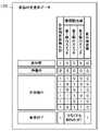
図4は、状態判定基準データ100のデータ構成例を示す図である。なお、以下、本実施形態においては変位部材の変位は合体作業の最後に行うべき合体完了操作であるものとして、説明する。
さて、状態判定基準データ100は、変形前(合体用変形する前;変形前形態の状態)と、待機中(合体前の合体用の変形状態;合体用形態)と、合体検出(合体はされたが変位部材の変位(本実施形態では合体完了)にまでは至っていない途中状態)と、合体完了(変位部材の変位完了)と、の4つの状態のうち何れに該当するかを判定するための定義データである。これら4つの状態は、合体用変形検出部60のON/OFF(図4ではON=1,OFF=0で表記)、種類検出部70の3つのスイッチのON/OFF、変位検出部(合体完了検出部)82のON/OFFの組み合わせで定義されている。FIG. 4 is a diagram showing a data configuration example of the state
Now, the state
図5は、種類判定基準データ102のデータ構成例を示す図である。
種類判定基準データ102は、制御主体玩具体10に合体された相手玩具体20の種類を判定するための定義データであって、種類検出部70の3つのスイッチ(第1検出スイッチ71、第2検出スイッチ72、第3検出スイッチ73)のON/OFF(図5中、ON=1、OFF=0で表記)の組み合わせで定義されている。なお、図5に示された種類判定基準データ102のデータ構成例はあくまで一例に過ぎない。例えば、相手玩具体20が3種類なのであれば、第1検出スイッチ71、第2検出スイッチ72のON/OFFの組み合わせで定義することも可能である。具体的には、第1検出スイッチ71のみがONのときは、図5におけるホーク号(第1種相手玩具体)が合体されたと判定し、第2検出スイッチ72のみがONのときは、ドリル号(第2種相手玩具体)が合体されたと判定し、第1スイッチ71と第2スイッチ72のいずれもONのときは、アーセナル号(第3種相手玩具体)が合体されたと判定するようすればよい。FIG. 5 is a diagram showing a data configuration example of the type
The type
図6は、演出パッケージ110のデータ構成例を示す図である。
演出パッケージ110は、初期状態で1つ又は複数が予め記憶されているが、別途、ユーザがインターネット等を通じて所定のウェブサイトから購入・ダウンロードして追加、或いは、適宜削除することができる。1つの演出パッケージ110は、固有のパッケージID112と、当該パッケージを制御に適用するための条件を定義する適用要件114と、合体待機演出データ116と、合体パターン別データセット120と、合体解除演出データ130と、を含む。FIG. 6 is a diagram showing a data configuration example of the
One or a plurality of
適用要件114は、例えば、標準設定を示す値、特定日、特定時間帯、合体開始から各状態が検出されるまでの所要時間などの、1つ又は複数の組み合わせによって記述される。 The
合体待機演出データ116は、合体待機演出を実現するためのデータである。具体的には、合体待機演出データ116は、合体用の変形操作がなされたことの検出をもって放音が開始され、合体が検出されるまでの間に放音される第1の種類の効果音の音声データである。特撮ヒーロー番組における合体シーンで言えば、当該シーンの開始とともに流れる勇ましいBGMがそれにあたる。合体待機演出データ116には、合体シーケンスに入った事を読み上げるナレーションの音声などを適宜含めることができる。合体待機音の種類はパッケージ別に設定可能であり、全てのパッケージで共通としても良いが、適用要件114の設定違いによって複数種類を用意してもよい。 The union
合体パターン別データセット120は、合体される制御主体玩具体10と相手玩具体20との組み合わせ、すなわち合体パターン毎に用意される。1つの合体パターン別データセット120は、固有のパターンID121と、適用要件123と、合体演出データ125と、合体完了演出データ127と、を含む。なお、本実施形態においては変位部材の変位を合体作業の最後に行うべき合体完了操作としているためデータ127を合体完了演出データと呼称するが、もし変位部材の変位が合体完了操作であない場合は、データ127は変位演出データと呼ぶべきものである。 The uniting pattern data set 120 is prepared for each combination of the controlling
適用要件123は、合体パターンを示す。具体的には、制御主体玩具体10の種類と、相手玩具体20の種類との組み合わせで記述される。なお、制御主体玩具体10の種類と、相手玩具体20の種類とが同じでも、合体する相対位置関係が異なることで複数のパターンが成立する場合(例えば、制御主体玩具体10が上+相手玩具体20が下のパターンと、相手玩具体20が上+制御主体玩具体10が下のパターン、などがある場合)は、適用要件123は、制御主体玩具体10の種類及び相手玩具体20の種類の組み合わせの条件に加えて、相対位置関係についての条件も適宜含めて定義する。
合体演出データ125は、合体を検出した際の演出を実現するためのデータであり、本実施形態では合体音の音声データである。合体音は、合体が検出された場合に再生・放音される効果音である。具体的には、合体音は、機械同士の接触や結合する際に発せられるエフェクト音(例えば、作動音・摺接音・衝突音など。カチッ、シュー、ガチャンなど。)、制御主体玩具体10の呼び名と相手玩具体20の呼び名を読み上げる音声、合体待機音に代わって再生されるBGM、のうちの1つ又は複数を含む。そして、合体音の内容は、データセットの種類別、つまり合体パターン別に異なる。 The
合体完了演出データ127は、合体完了時の演出を実現するためのデータであり、本実施形態では合体完了音の音声データである。合体完了音は、合体完了の検出がなされた場合に再生・放音される効果音である。具体的には、合体完了音は、機械同士の接触や結合する際に発せられるエフェクト音、合体完了形態である巨大人型ロボット30の呼び名を読み上げる音声、合体完了を告げるエフェクト音(例えば、シャキーン、ズキューンなど。)、合体完了を告げるファンファーレなどのBGM、のうちの1つ又は複数を含む。そして、合体完了音の内容は、データセットの種類別、つまり合体パターン別に異なる。なお、本実施形態においては変位部材の変位を合体作業の最後に行うべき合体完了操作としているためデータ127を合体完了時の演出を実現するためのデータとしているが、もし変位部材の変位が合体完了操作でない場合は、データ127は当該変位時の演出を実現するためのデータとなる。具体的には、変形時の演出は、機械同士の摺動時に発せられるエフェクト音などが考えられる。 The combination
合体解除演出データ130は、合体解除の演出を実現させるためのデータであり、本実施形態では合体解除音の音声データである。合体解除音は、合体完了の状態から他の状態へ変化した場合に再生・放音される効果音である。具体的には、機械同士の接触や結合する際に発せられるエフェクト音、解除されたことを述べる音声、などの1つ又は複数を含む。合体解除音の内容は、パッケージで共通としても良いし、データセットの種類別、つまり合体パターン別に異なるとしてもよい。 The union
図7は、制御主体玩具体10の変形前形態から合体用形態への変形と、それに伴う合体用変形検出部60及び種類検出部70の状態の変化を説明するための図である。図7中の引き出し部分は、合体用変形検出部60及び種類検出部70周りの拡大図に相当する。 FIG. 7 is a diagram for explaining the deformation of the control
図7(1)に示すように、変形前形態の制御主体玩具体10では、合体用変形検出部60のスイッチは、装備ラック17に対する第1基部11の対向面に設けられた凹部内に、当該スイッチの作動部が突出するように設置されている。装備ラック17は、第1基部11との対向面に凸部19を有しており、変形前形態では当該凸部19が合体用変形検出部60のスイッチを押すことでONになっている。しかし、装備ラック17には、種類検出部70の3つのスイッチ(第1検出スイッチ71、第2検出スイッチ72、第3検出スイッチ73)に対応する凸部が無いため、これら3つのスイッチはOFFになっている。 As shown in FIG. 7(1), in the control
制御主体玩具体10を、変形前形態から合体用形態に変形するには、ユーザは変形操作を行う。具体的には、図7(2)に示すように、第1基部11の上で折りたたまれていた装備ラック17を後方へ伸ばす。次いで、図7(3)に示すように、ユーザは、大型火砲15を装備ラック17から取り外して第2基部12の下面に装着する。また、頭部13を上下反転させた後に上面側へスライドさせる。脚部14は、それぞれ前方へスライドさせるとともに、前後を反転させる。次いで、図7(4)に示すように、ユーザは、一方の脚部14(図7の手前側)を折りたたまれた状態から伸ばす状態とし、他方の脚部14(図7の奥側)を折りたたまれた状態から更に折りたたんだ状態として背面側(図7の奥側)へスイングさせる。以上により、合体用形態となる。 In order to transform the control
合体用形態の制御主体玩具体10(10h)は、巨大人型ロボット30の右半身となる。すなわち、第1基部11は巨大人型ロボット30の右胸部、第2基部12は右腰部、頭部13は右頭部カバー、脚部14の一方は右腕部、脚部14の他方は背面装備、大型火砲15は腰の位置へ移動、装備ラック17は右脚部となる。制御主体玩具体10の頭部13,脚部14,大型火砲15,装備ラック17は、制御主体玩具体10にとっての変形前形態から合体用形態に変位可能な変位部位6であると言える。 The control subject toy body 10 ( 10 h ) in the union form is the right half of the giant
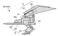
図8は、相手玩具体20(20a)の構成例を示す図であって、変形前形態における相手玩具体20(20a)の側面図に相当する。
相手玩具体20(20a)は、例えば関節構造やスライド構造等の可動構造によって相互に連結された複数の部位で構成されている。具体的には、相手玩具体20は、第1基部21と、第2基部22と、頭部23と、脚部24と、当該種類の固有装備(翼25及び剣26)と、装備ラック27と、を有する。頭部23,脚部24,翼25,剣26,装備ラック27は、相手玩具体20にとっての変形前形態から合体用形態に変位可能な変位部位6である。そして、制御主体玩具体10では第1基部11の内部に制御部50が搭載されていたが、相手玩具体20には搭載されておらず、合体玩具2の全体としてのコスト低減に寄与している。また、頭部23は、図8において、下側が開口した中空空間を形成しており、当該空間に巨大人型ロボット30の頭部33の左半体33Lを内蔵している。FIG. 8 is a diagram showing a configuration example of the mating toy 20 (20a), and corresponds to a side view of the mating toy 20 (20a) in the pre-deformation form.
The mating toy body 20 (20a) is composed of a plurality of parts that are interconnected by a movable structure such as a joint structure or a slide structure. Specifically, the
脚部24及び装備ラック27は、それぞれ複数の部位が可動連結した多関節構造を有する。装備ラック27には、翼25が着脱自在であり、第1基部11には、剣26が着脱自在となっている。 The
相手玩具体20は、変形されることによって巨大人型ロボット30の左半身となる。相手玩具体20の変形は、基本的には制御主体玩具体10と同様である。すなわち、ユーザは、相手玩具体20の固有装備(図8の例では翼25,剣26)を外して、装備ラック27を伸ばし、脚部14を反転させて一方の脚を伸ばし、他方の脚を折り畳んでスイングさせる。そして、ユーザは、頭部23をスライドして反転させ、外した固有装備を所定位置に取り付けて合体用形態に変形させる。 The
図9~図11は、制御主体玩具体10と相手玩具体20(20a)との合体を説明するための図であって、図9~11の順に状態遷移する。なお、図中の引き出し部分は、合体用変形検出部60及び種類検出部70周りの拡大図に相当する。 9 to 11 are diagrams for explaining the combination of the controlling
図9に示すように、合体用形態に変形された制御主体玩具体10(10h)は、巨大人型ロボット30の右半身の形状をなし、合体用形態に変形された相手玩具体20(20h)は、巨大人型ロボット30の左半身の形状をなしている。この時の合体用変形検出部60及び種類検出部70に着目すると、合体用変形検出部60のスイッチと、種類検出部70の3つのスイッチ(第1検出スイッチ71,第2検出スイッチ72,第3検出スイッチ73)はどれもOFFである。 As shown in FIG. 9, the control subject toy body 10 (10h) transformed into the combination form has the shape of the right half of the giant
ユーザは、合体用形態に変形された制御主体玩具体10(10h)の左面と、合体用形態に変形された相手玩具体20(20h)の右面とを対向させて密着・連結させる。この連結操作によって、図10のように、2つの玩具体が連結構造部90によって一体に結合される。 The user causes the left face of the control subject toy body 10 (10h) transformed into the union form to face the right face of the mating toy body 20 (20h) transformed into the union form, and brings them into close contact and connection. By this connecting operation, the two toy bodies are integrally connected by the connecting
具体的には、連結構造部90として、合体用形態に変形された制御主体玩具体10(10h)の左面と、合体用形態に変形された相手玩具体20(20h)の右面には、対向位置に、カギ爪状の第1係合部91或いは第2係合部92を有する(図9参照)。連結操作によってこれらが係合し合って連結する。なお、連結構造部90は、カギ爪式に限らない。例えば、制御主体玩具体10及び相手玩具体20の一方に磁石を内蔵し、他方に鉄片を埋め込んでおいて磁力で連結させるとしてもよい。 Specifically, as the connecting
また、制御主体玩具体10(10h)の頭部13と、相手玩具体20(20h)の頭部23とが密着し、これらの内部空間では右半体33Rと左半体33Lとが密着・結合して、巨大人型ロボット30の頭部33を形作る。 Also, the
なお、頭部33を、右半体33Rと左半体33Lとに分割する場合の分割の仕方は、頭部33のデザイン等に応じて適宜設定可能である。例えば、頭部33がヘルメット状の防具を装備した西洋騎士風のデザインであれば、左半体33Lを顔部分とヘルメット状防具の左半分、右半体33Rをヘルメット状防具の右半分、と言った具合に分割してもよい。この場合、組み合わされる制御主体玩具体10の種類と相手玩具体20の種類とに応じて、顔部分のデザインを変更すると好適である。右半体33Rと左半体33との連結構造は、インロウ構造や磁力による連結などを適宜採用することができる。 The method of dividing the
ここで、合体用変形検出部60及び種類検出部70に着目すると、本実施形態においては、連結・合体によって相手玩具体20(20h)の右面に設けられた合体検出用凸部28gが、合体用変形検出部60を押してスイッチをONにする。なお、後述する種類判定用凸部28sが種類検出部70のスイッチのうちいずれか1つがONにすることによって合体を検出するようにするならば、合体検出用凸部28gについては省略可能である。その場合、種類検出部70が本発明にいう合体検出部を兼ねることになる。 Here, focusing on the union
また、相手玩具体20(20h)の右面には種類判定用凸部28sが設けられている。種類判定用凸部28sは、相手玩具体20の種類に応じて、数と配置の組み合わせが異なるように設定されており、合体にともなって種類検出部70の3つのスイッチのうち少なくとも1つをONにする。種類判定用凸部28sは、突起で実現され、種類検出部70のスイッチと1対1に対応する位置に存在するか否かで、相手玩具体20の種類が特定されるようになっている。図10では、第3検出スイッチ73を押す種類判定用凸部28sを1つだけ備える例が示されている。連結・合体によって、種類検出部70の3つのスイッチは、合体された相手玩具体20の種類に応じたON/OFFの状態となる。 In addition, a
連結操作したならば、図11に示すように、ユーザは合体完了操作をする。合体完了操作として、制御主体玩具体10(10h)の頭部13(本発明にいう「変位部材」)を外側へ揺動させる(変位させる)とともに、相手玩具体20(20h)の頭部23を外側へ揺動させる。すなわち、連結操作直後においては、頭部13と頭部23は巨大人型ロボット30の正中線で向かい合って密着しているが(図10参照)、これらの上端部を互いに離隔するように展開させる。そして、中から巨大人型ロボット30のロボット頭部33が出現する。 After performing the connection operation, the user performs a union completion operation as shown in FIG. As a combination completion operation, the head 13 (the "displacement member" in the present invention) of the control subject toy 10 (10h) is swung (displaced) outward, and the
変位検出部(合体完了検出部)82のスイッチは、頭部13の揺動によって押下される位置に設置されている。よって、合体完了操作(本実施形態においては、頭部13の揺動、つまり、変位部材の変位を合体作業の最後に行うべき合体完了操作としている)によって、変位検出部(合体完了検出部)82はOFFからONになる。 The switch of the displacement detection section (combination completion detection section) 82 is installed at a position where it is pushed down by the swinging of the
次に、合体玩具2の変形合体に伴う効果音の自動放音について説明する。
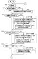
図12は、変形合体に係る制御部50による処理の流れを説明するための図である。電源がONになると、CPU51は自動的に制御プログラムを読み込んで実行し、ここで説明する処理を開始する。Next, the automatic sound emission of sound effects accompanying deformation and combination of the
FIG. 12 is a diagram for explaining the flow of processing by the
まず、CPU51は、合体用変形検出部60・種類検出部70・合体検出部80・変位検出部(合体完了検出部)82からの検出信号の入力状況(ON/OFF)を状態判定基準データ100と照合(図4参照)し、今現在の制御主体玩具体10の状態を判定する(ステップS2)。判定結果は、RAM52にて一時保存される。 First, the
状態判定の結果、ユーザにより合体用変形操作が行われたことで状態が「変形前」から「待機中」へ変化したと判定される場合、言い換えると変形操作が検出された場合(ステップS4のYES)、CPU51は待機中制御として合体待機演出の出力、すなわち合体待機音の再生出力を開始する(ステップS6)。具体的には、演出パッケージ110(図6参照)の中から適用要件114を満たすパッケージを検索し、検索されたパッケージの合体待機演出データ116を読み出して音声の再生出力を開始する。なお、CPU51は、合体待機演出の出力回数或いは出力継続時間をRAM52に一時的に保存し、出力回数が所定の上限回数に達した場合或いは出力継続時間が所定時間長に達した場合は、演出出力を停止させる。 As a result of the state determination, if it is determined that the state has changed from "pre-deformation" to "waiting" due to the user's transforming operation for combining, in other words, if the transforming operation is detected (step S4). YES), the
状態判定の結果、「待機中」から「合体検出」へ状態が変化した場合、言い換えると合体操作が検出された場合(ステップS10のYES)、CPU51は、合体時制御としてステップS12~ステップS16を実行する。 As a result of the state determination, if the state changes from "waiting" to "detected union", in other words, if a union operation is detected (YES in step S10), the
すなわち、CPU51は、種類検出部70の3つのスイッチのON/OFF状況を、種類判定基準データ102(図5参照)と照合して、合体された相手玩具体20の種類を判定する(ステップS12)。次いで、CPU51は、合体された相手玩具体20の種類に対応する合体演出データ125(図6参照)を検索・参照し(ステップS14)、合体待機演出の出力として合体待機音の再生出力を停止して検索されたデータの合体音の再生出力を開始する(ステップS16)。なお、CPU51は、合体演出の出力回数或いは出力継続時間をRAM52に保存し、出力回数が所定の上限回数に達した場合或いは出力継続時間が所定時間長に達した場合は、演出出力を停止させる。 That is, the
状態判定の結果、「合体検出」から「合体完了」へ状態が変化した場合(本実施形態においては、変位部材の変位を合体作業の最後に行うべき合体完了操作としているので「合体完了」へ状態が変化した場合としているが、別言すれば「変位部材が変位した場合」である。)、言い換えると合体完了操作(変位部材を変位させる操作)を検出した場合(ステップS20のYES)、CPU51は、合体完了時制御(変位時制御)としてステップS22~ステップS24を実行する。 As a result of the state determination, if the state changes from "union detected" to "union completed" (in this embodiment, displacement of the displaceable member is the union completion operation that should be performed at the end of the union operation, so the state changes to "union completed"). In other words, when the union completion operation (operation to displace the displacement member) is detected (YES in step S20), The
すなわち、CPU51は、合体された相手玩具体20の種類に対応する合体完了演出データ127(図6参照)を検索・参照し(ステップS22)、合体完了演出の出力として、合体音の再生出力を停止して検索されたデータの合体完了音の再生出力を開始する(ステップS24)。なお、CPU51は、合体完了演出の出力回数或いは出力継続時間をRAM52に一時的に保存し、出力回数が所定の上限回数に達した場合或いは出力継続時間が所定時間長に達した場合は、演出出力を停止させる。 That is, the
状態判定の結果、「合体完了」から他の状態に変化した場合、言い換えると合体解除操作を検出した場合(ステップS30のYES)、CPU51は、合体解除制御として、出力中の演出を中止し、合体解除演出データ130(図6参照)を検索・参照して、合体解除演出の出力として、検索されたデータの合体解除音の再生出力を開始する(ステップS32)。 As a result of the state determination, if the state changes from "completion of union" to another state, in other words, if a union cancellation operation is detected (YES in step S30), the
以上、本実施形態によれば、変形合体操作を盛り上げる演出出力を、合体のための変形操作に連動して自動的に出力できる合体玩具を実現できる。従来のように、変形合体操作をする前に、ユーザ自らがわざわざ効果音を再生出力させるスイッチを操作する必要が無く、変形合体の操作に伴って効果音が再生出力され、また、変形合体の操作の進行に伴って効果音が変化するため、没入感を削がれることなく変形合体の操作をする気分を盛り上げることができる。また、変形合体操作におけるクライマックスであるロボット頭部に係る操作を検出し、当該操作とともに演出が出力されるため興趣性が高く、しかも、当該演出は変形合体に係る演出のクライマックスである合体完了演出であるのでより一層気分を盛り上げることができる。 As described above, according to the present embodiment, it is possible to realize a united toy that can automatically output an effect output that enlivens the transforming uniting operation in conjunction with the transforming operation for uniting. The user does not need to manually operate a switch for reproducing sound effects before performing a transforming/merging operation, as in the conventional art. Since the sound effect changes as the operation progresses, the feeling of transforming and coalescing can be enhanced without sacrificing the sense of immersion. In addition, since an operation related to the robot head, which is the climax of the transforming/merging operation, is detected, and an effect is output along with the operation, it is highly interesting, and the effect is the climax of the effect related to transforming/merging, which is the union completion effect. So it can make you feel even better.
〔変形例〕
本発明を適用可能な実施形態は、上記の例に限らず適宜構成要素の追加・省略・変更が可能である。[Modification]
Embodiments to which the present invention can be applied are not limited to the above examples, and addition, omission, and modification of constituent elements are possible as appropriate.
(変形例その1)
例えば、本発明が適用された合体玩具2の合体完了後の姿の例として、人型ロボット兵器の例を示したが、合体完了後の姿はこれに限たない。例えば、獣型や昆虫型のロボット兵器、多脚の戦車、などであってもよい。そして、合体用変形検出部60と、種類検出部70と、合体検出部80と、変位検出部(合体完了検出部)82の設置位置は、変形の前後や合体の前後で離隔/接合する箇所、或いは相対角度や相対位置が変化する箇所であれば、そのデザインに応じて適宜設定可能である。(Modification 1)
For example, a humanoid robot weapon is shown as an example of the combined
(変形例その2)
また、上記実施形態では、合体用変形検出部60と、種類検出部70と、合体検出部80と、変位検出部(合体完了検出部)82と、を小型のプッシュスイッチで実現する例を示したが、各検出部は、その他のスイッチやセンサ等によって実現してもよい。例えば、プッシュスイッチに代えて2つの電極を用い、合体検出用凸部28gや種類判定用凸部28sの先端に、2つの電極に同時に接触して電気を導通させる導電材を取り付けておくことで実現してもよい。或いは、プッシュスイッチに代えてホールセンサを用い、合体検出用凸部28gや種類判定用凸部28sの先端に小さな磁石を内蔵させて実現してもよい。(Modification 2)
Further, in the above-described embodiment, an example is shown in which the combination
(変形例その3)
また、上記実施形態では、演出出力を効果音の放音により実現する例を示したが、放音に限らず、発光や振動などを演出に用いることもできる。その場合、演出出力部56の出力形態に応じた制御ICを適宜制御部50に加えるとよい。例えば、演出として発光や画像表示を行う場合には、演出出力部56としてLED等の発光素子やLCD等の表示素子を搭載し、適宜、制御部50にそれらの制御ドライバー回路を搭載するとよい。また、演出として振動を用いる場合には、演出出力部56としてバイブレータを搭載し、制御部50に加振制御用のICを搭載するとよい。(Modification 3)
Further, in the above-described embodiment, an example in which the production output is realized by emitting sound effects has been shown, but it is also possible to use not only the emission of sound but also light emission, vibration, etc. for the production. In that case, a control IC corresponding to the output mode of the
2…合体玩具
4…ICメモリーカード
6…変位部位
10…制御主体玩具体
11…第1基部
12…第2基部
13…頭部
14…脚部
15…大型火砲
17…装備ラック
19…凸部
20…相手玩具体
21…第1基部
22…第2基部
23…頭部
24…脚部
25…翼
26…剣
27…装備ラック
28g…合体検出用凸部
28s…種類判定用凸部
30…巨大人型ロボット
33…ロボット頭部
33R…右半体
33L…左半体
50…制御部
51…CPU
52…RAM
53…ROM
54…リーダ
55…電池
56…演出出力部
60…合体用変形検出部
70…種類検出部
71…第1検出スイッチ
72…第2検出スイッチ
73…第3検出スイッチ
80…合体検出部
82…変位検出部(合体完了検出部)
90…連結構造部
91…第1係合部
92…第2係合部
100…状態判定基準データ
102…種類判定基準データ
110…演出パッケージ
112…パッケージID
114…適用要件
116…合体待機演出データ
120…合体パターン別データセット
121…パターンID
123…適用要件
125…合体演出データ
127…合体完了演出データ(変位演出データ)
130…合体解除演出データ2
52 RAM
53 ROM
54...
90 --
114
123
130 … Uncoupling effect data
Claims (13)
Translated fromJapanese前記複数の玩具体は、一体の制御主体玩具体と、その他の相手玩具体とであり、
前記制御主体玩具体は、
演出出力部と、
前記変形前形態からの形態変形を検出する合体用変形検出部と、
前記相手玩具体が合体したことを検出する合体検出部と、
合体前状態から変位可能な変位部材と、
前記変位部材が変位したことを検出する変位検出部と、
前記合体用変形検出部による検出に応じて所与の合体待機演出を前記演出出力部から出力開始させる待機中制御と、前記合体検出部による検出後において前記変位検出部による検出に応じて所与の変位演出を前記演出出力部から出力させる変位時制御と、を実行する制御部と、
を備える、
合体玩具。A combined toy comprising a plurality of shape-deformable toy bodies, wherein the toy bodies transformed from a pre-deformation form to a combination form can be combined with each other,
the plurality of toy bodies are an integrated control subject toy body and other mating toy bodies,
The control subject toy body
a performance output unit;
a merging deformation detection unit that detects a form deformation from the pre-deformation form;
a combination detection unit for detecting that the mating toy bodies are combined;
a displacement member that can be displaced from a pre-union state;
a displacement detection unit that detects that the displacement member has been displaced;
standby control for starting to output a given coalescence standby effect from the effect output unit in response to detection by the deformation detection unit for coalescence; a control unit that executes a displacement time control that outputs a displacement effect of from the effect output unit;
comprising
Combined toy.
請求項1に記載の合体玩具。The control unit executes a combination control that outputs a given combination effect from the effect output unit in response to detection by the combination detection unit.
The united toy according to claim 1.
請求項2に記載の合体玩具。The uniting time control is a control for outputting the uniting effect after stopping the output of the uniting standby effect in response to detection by the uniting detection unit.
The united toy according to claim 2.
前記制御主体玩具体は、
合体した前記相手玩具体の種類を検出する種類検出部、
を更に備え、
前記演出出力部は、少なくともスピーカを含み、
前記合体時制御は、前記種類検出部により検出された種類に応じた前記相手玩具体の名称を含む音声を前記合体演出として前記スピーカから放音させる制御である、
請求項2又は3に記載の合体玩具。The mating toy body has a plurality of types that can be combined with the control subject toy body,
The control subject toy body
a type detection unit for detecting the type of the combined mating toy body;
further comprising
The effect output unit includes at least a speaker,
The merging control is a control for emitting a sound including the name of the mating toy body corresponding to the type detected by the type detecting unit from the speaker as the merging effect.
The united toy according to claim 2 or 3.
前記合体時制御を実行した後に、前記合体検出部による検出が解除された場合に、所与の合体解除演出を前記演出出力部から出力させる合体解除制御を実行する、
請求項2~4の何れか一項に記載の合体玩具。The control unit
After the uniting time control is executed, when the detection by the uniting detecting unit is canceled, uniting cancellation control is executed to output a given uniting cancellation effect from the production output unit.
The united toy according to any one of claims 2-4.
前記制御主体玩具体は、
合体した前記相手玩具体の種類を検出する種類検出部、
を更に備え、
前記種類検出部が前記合体検出部を兼ねており、
前記制御部は、前記種類検出部による合体した前記相手玩具体の種類の検出に応じて前記合体時制御を実行する、
請求項2~5の何れか一項に記載の合体玩具。The mating toy body has a plurality of types that can be combined with the control subject toy body,
The control subject toy body
a type detection unit for detecting the type of the combined mating toy body;
further comprising
The type detection unit also serves as the combination detection unit,
The control unit executes the combination control in response to detection of the type of the combined mating toy body by the type detection unit.
The united toy according to any one of claims 2-5.
前記制御主体玩具体は、
合体した前記相手玩具体の種類を検出する種類検出部、
を更に備え、
前記変位時制御は、前記種類検出部により検出された種類に応じて異なる前記変位演出を前記演出出力部から出力させる制御である、
請求項1~6の何れか一項に記載の合体玩具。The mating toy body has a plurality of types that can be combined with the control subject toy body,
The control subject toy body
a type detection unit for detecting the type of the combined mating toy body;
further comprising
The control at the time of displacement is a control for outputting a different displacement effect from the effect output unit according to the type detected by the type detection unit.
Combined toy according to any one of claims 1-6.
前記制御主体玩具体に合体する際の前記種類検出部に対向する位置に、当該相手玩具体の種類に応じて、数と配置の組み合わせが異なる凸部、
を備え、
前記種類検出部は、合体した前記相手玩具体の種類を、前記凸部の数と配置の組み合わせに基づいて検出する、
請求項4又は7に記載の合体玩具。The mating toy body is
Protrusions having different combinations of number and arrangement according to the type of the mating toy body at a position facing the type detection section when the control subject toy body is combined,
with
The type detection unit detects the type of the combined mating toy body based on a combination of the number and arrangement of the protrusions.
Combined toy according to claim 4 or 7.
前記変位検出部は、前記変位部材が前記合体完了状態にあることを検出する合体完了検出部であり、
前記制御部は、前記変位時制御として、前記合体完了検出部による検出に応じて所与の合体完了演出を前記演出出力部から出力される合体完了時制御を、実行する制御部と、
を備える請求項1~8の何れか一項記載の合体玩具。The displacing member can be displaced from a pre-union state to a state of completion of unification by being displaced,
The displacement detection unit is a combination completion detection unit that detects that the displacement member is in the combination complete state,
The control unit executes, as the displacement control, a combination completion control in which a given combination completion effect is output from the effect output unit in response to detection by the combination completion detection unit;
The united toy according to any one of claims 1 to 8, comprising:
請求項9記載の合体玩具。The merging completion control is a control for outputting the merging completion effect when detection is made by the merging detection unit and detection is made by the merging completion detection unit.
10. The united toy according to claim 9.
演出出力部と、
前記変形前形態からの形態変形を検出する合体用変形検出部と、
前記相手玩具体が合体したことを検出する合体検出部と、
合体前状態から変位可能な変位部材と、
前記変位部材が変位したことを検出する変位検出部と、
前記合体用変形検出部による検出に応じて所与の合体待機演出を前記演出出力部から出力開始させる待機中制御と、前記合体検出部による検出後において前記変位検出部による検出に応じて所与の変位演出を前記演出出力部から出力させる変位時制御と、を実行する制御部と、
を備える制御主体玩具体。The controlling subject toy body transformed from the pre-deformation form to the combining form is combined with one or more mating toy bodies to form a combined toy,
a performance output unit;
a merging deformation detection unit that detects a form deformation from the pre-deformation form;
a combination detection unit for detecting that the mating toy bodies are combined;
a displacement member that can be displaced from a pre-union state;
a displacement detection unit that detects that the displacement member has been displaced;
standby control for starting to output a given coalescence standby effect from the effect output unit in response to detection by the deformation detection unit for coalescence; a control unit that executes a displacement time control that outputs a displacement effect of from the effect output unit;
A controlling subject toy body comprising:
前記変位検出部は、前記変位部材が前記合体完了状態にあることを検出する合体完了検出部であり、
前記制御部は、前記変位時制御として、前記合体完了検出部による検出に応じて所与の合体完了演出を前記演出出力部から出力される合体完了時制御を、実行する制御部と、
を備える請求項11記載の制御主体玩具体。The displacing member can be displaced from a pre-union state to a state of completion of unification by being displaced,
The displacement detection unit is a combination completion detection unit that detects that the displacement member is in the combination complete state,
The control unit executes, as the displacement control, a combination completion control in which a given combination completion effect is output from the effect output unit in response to detection by the combination completion detection unit;
12. The controlling subject toy body according to claim 11, comprising:
13. The mating toy body unitable with the controlling subject toy body according to claim 11 or 12, wherein said mating toy body is transformed from said pre-deformation form to said combination form.
Priority Applications (7)
| Application Number | Priority Date | Filing Date | Title |
|---|---|---|---|
| JP2020198898AJP7204722B2 (en) | 2020-11-30 | 2020-11-30 | Combined toy, control subject toy body and companion toy |
| PCT/JP2021/040222WO2022113660A1 (en) | 2020-11-30 | 2021-11-01 | Combination toy, control subject toy body, and partner toy |
| KR1020210157189AKR102643870B1 (en) | 2020-11-30 | 2021-11-16 | Combined toys, control main toy body and partner toy |
| CN202111399945.1ACN114247155B (en) | 2020-11-30 | 2021-11-19 | Combined toys, controlling the main body to play with the concrete and playing with the concrete |
| CN202310345124.2ACN116328323A (en) | 2020-11-30 | 2021-11-19 | Combined toys, controlling the main body to play with the concrete and playing with the concrete |
| JP2022211481AJP7732967B2 (en) | 2020-11-30 | 2022-12-28 | Combination toy, controlling toy body and partner toy |
| KR1020240029448AKR20240032791A (en) | 2020-11-30 | 2024-02-29 | Combined toys, control main toy body and partner toy |
Applications Claiming Priority (1)
| Application Number | Priority Date | Filing Date | Title |
|---|---|---|---|
| JP2020198898AJP7204722B2 (en) | 2020-11-30 | 2020-11-30 | Combined toy, control subject toy body and companion toy |
Related Child Applications (1)
| Application Number | Title | Priority Date | Filing Date |
|---|---|---|---|
| JP2022211481ADivisionJP7732967B2 (en) | 2020-11-30 | 2022-12-28 | Combination toy, controlling toy body and partner toy |
Publications (2)
| Publication Number | Publication Date |
|---|---|
| JP2022086722A JP2022086722A (en) | 2022-06-09 |
| JP7204722B2true JP7204722B2 (en) | 2023-01-16 |
Family
ID=80793123
Family Applications (2)
| Application Number | Title | Priority Date | Filing Date |
|---|---|---|---|
| JP2020198898AActiveJP7204722B2 (en) | 2020-11-30 | 2020-11-30 | Combined toy, control subject toy body and companion toy |
| JP2022211481AActiveJP7732967B2 (en) | 2020-11-30 | 2022-12-28 | Combination toy, controlling toy body and partner toy |
Family Applications After (1)
| Application Number | Title | Priority Date | Filing Date |
|---|---|---|---|
| JP2022211481AActiveJP7732967B2 (en) | 2020-11-30 | 2022-12-28 | Combination toy, controlling toy body and partner toy |
Country Status (4)
| Country | Link |
|---|---|
| JP (2) | JP7204722B2 (en) |
| KR (2) | KR102643870B1 (en) |
| CN (2) | CN114247155B (en) |
| WO (1) | WO2022113660A1 (en) |
Families Citing this family (2)
| Publication number | Priority date | Publication date | Assignee | Title |
|---|---|---|---|---|
| JP7717882B1 (en)* | 2024-03-21 | 2025-08-04 | 株式会社バンダイ | toy |
| JP7743593B1 (en) | 2024-12-03 | 2025-09-24 | 株式会社バンダイ | Performance output toys |
Citations (6)
| Publication number | Priority date | Publication date | Assignee | Title |
|---|---|---|---|---|
| JP2003210843A (en) | 2002-01-24 | 2003-07-29 | Takara Co Ltd | Video game toys |
| JP3177319U (en) | 2012-05-18 | 2012-07-26 | 有限会社イング二十一 | Shape change toy |
| JP3181339U (en) | 2012-11-20 | 2013-01-31 | 株式会社タカラトミー | Shape change toy |
| JP2014108288A (en) | 2012-12-03 | 2014-06-12 | Bandai Co Ltd | Action toy |
| JP2016185222A (en) | 2015-03-27 | 2016-10-27 | 株式会社バンダイ | toy |
| JP2018086120A (en) | 2016-11-29 | 2018-06-07 | 株式会社バンダイ | toy |
Family Cites Families (10)
| Publication number | Priority date | Publication date | Assignee | Title |
|---|---|---|---|---|
| JPH0538784Y2 (en)* | 1986-11-29 | 1993-09-30 | ||
| JPH0653196B2 (en)* | 1986-12-27 | 1994-07-20 | 株式会社タカラ | Transformable toy |
| JPH0626987U (en)* | 1991-06-05 | 1994-04-12 | 株式会社タカラ | Combined transformation toy |
| KR200207540Y1 (en)* | 2000-07-21 | 2000-12-15 | 이재호 | Plaything having apparatus of moving induction |
| JP5939691B2 (en) | 2014-03-31 | 2016-06-22 | 株式会社バンダイ | Response toy and main toy body |
| JP5802322B1 (en)* | 2014-12-02 | 2015-10-28 | 株式会社バンダイ | Production toy |
| JP6304843B2 (en)* | 2016-11-24 | 2018-04-04 | 株式会社バンダイ | Toy |
| JP6373435B1 (en) | 2017-03-27 | 2018-08-15 | 株式会社バンダイ | Production output toy |
| JP6462099B1 (en)* | 2017-12-01 | 2019-01-30 | 株式会社バンダイ | Production output toy |
| CN109966750B (en)* | 2019-03-29 | 2020-12-22 | 浙江传媒学院 | A voice-activated splicing toy |
- 2020
- 2020-11-30JPJP2020198898Apatent/JP7204722B2/enactiveActive
- 2021
- 2021-11-01WOPCT/JP2021/040222patent/WO2022113660A1/ennot_activeCeased
- 2021-11-16KRKR1020210157189Apatent/KR102643870B1/enactiveActive
- 2021-11-19CNCN202111399945.1Apatent/CN114247155B/enactiveActive
- 2021-11-19CNCN202310345124.2Apatent/CN116328323A/enactivePending
- 2022
- 2022-12-28JPJP2022211481Apatent/JP7732967B2/enactiveActive
- 2024
- 2024-02-29KRKR1020240029448Apatent/KR20240032791A/enactivePending
Patent Citations (6)
| Publication number | Priority date | Publication date | Assignee | Title |
|---|---|---|---|---|
| JP2003210843A (en) | 2002-01-24 | 2003-07-29 | Takara Co Ltd | Video game toys |
| JP3177319U (en) | 2012-05-18 | 2012-07-26 | 有限会社イング二十一 | Shape change toy |
| JP3181339U (en) | 2012-11-20 | 2013-01-31 | 株式会社タカラトミー | Shape change toy |
| JP2014108288A (en) | 2012-12-03 | 2014-06-12 | Bandai Co Ltd | Action toy |
| JP2016185222A (en) | 2015-03-27 | 2016-10-27 | 株式会社バンダイ | toy |
| JP2018086120A (en) | 2016-11-29 | 2018-06-07 | 株式会社バンダイ | toy |
Also Published As
| Publication number | Publication date |
|---|---|
| CN116328323A (en) | 2023-06-27 |
| WO2022113660A1 (en) | 2022-06-02 |
| JP2022086722A (en) | 2022-06-09 |
| KR20240032791A (en) | 2024-03-12 |
| JP7732967B2 (en) | 2025-09-02 |
| KR102643870B1 (en) | 2024-03-07 |
| CN114247155B (en) | 2023-04-21 |
| CN114247155A (en) | 2022-03-29 |
| KR20220076317A (en) | 2022-06-08 |
| JP2023026532A (en) | 2023-02-24 |
Similar Documents
| Publication | Publication Date | Title |
|---|---|---|
| JP2023026532A (en) | Combined toy, control subject toy body and companion toy | |
| US8157611B2 (en) | Interactive toy system | |
| US8419541B2 (en) | Smart shell to a game controller | |
| US20070093172A1 (en) | Interactive toy system | |
| CN108671553B (en) | doll toy | |
| US20160136534A1 (en) | Programmable Interactive Toy | |
| WO1999054016A9 (en) | Light shooting and detecting toy figures | |
| WO2001062359A1 (en) | Sanity system for video game | |
| EP1776990A2 (en) | Interactive toy system | |
| JP6971175B2 (en) | Doll toys | |
| KR20050048648A (en) | Animated multi-persona toy | |
| JP3532898B2 (en) | Video game toys | |
| US20060205318A1 (en) | Modular miniature figures | |
| JP6980078B2 (en) | Humanoid toys | |
| JPS6341025Y2 (en) | ||
| US20010041617A1 (en) | Video game apparatus, character-behavior-instructing method in video game, and machine-readable-recording medium recording character-behavior-instructing program | |
| RU2770761C1 (en) | Interactive doll control system | |
| JP2003210836A (en) | Video game toys | |
| KR200291736Y1 (en) | Block Toys for Increasing Creativity | |
| CN215025966U (en) | Toy | |
| US20190375533A1 (en) | System for action figure entertainment | |
| Kang | A Real-time Strategy Game in the Form of Character Switching: Soul Swapper | |
| KR200308739Y1 (en) | Matrix Block Type Digital Toys using Digital Electronic Circuit | |
| Boehnke | Horror: Where are we? Where do we go? | |
| JP2001054685A (en) | Simulated play toys |
Legal Events
| Date | Code | Title | Description |
|---|---|---|---|
| A621 | Written request for application examination | Free format text:JAPANESE INTERMEDIATE CODE: A621 Effective date:20201201 | |
| A131 | Notification of reasons for refusal | Free format text:JAPANESE INTERMEDIATE CODE: A131 Effective date:20220112 | |
| A521 | Request for written amendment filed | Free format text:JAPANESE INTERMEDIATE CODE: A523 Effective date:20220114 | |
| A131 | Notification of reasons for refusal | Free format text:JAPANESE INTERMEDIATE CODE: A131 Effective date:20220516 | |
| A603 | Late request for extension of time limit during examination | Free format text:JAPANESE INTERMEDIATE CODE: A603 Effective date:20220720 | |
| A521 | Request for written amendment filed | Free format text:JAPANESE INTERMEDIATE CODE: A523 Effective date:20220907 | |
| TRDD | Decision of grant or rejection written | ||
| A01 | Written decision to grant a patent or to grant a registration (utility model) | Free format text:JAPANESE INTERMEDIATE CODE: A01 Effective date:20221207 | |
| A61 | First payment of annual fees (during grant procedure) | Free format text:JAPANESE INTERMEDIATE CODE: A61 Effective date:20221228 | |
| R150 | Certificate of patent or registration of utility model | Ref document number:7204722 Country of ref document:JP Free format text:JAPANESE INTERMEDIATE CODE: R150 |