JP7203588B2 - Heat treatment equipment - Google Patents
Heat treatment equipmentDownload PDFInfo
- Publication number
- JP7203588B2 JP7203588B2JP2018235169AJP2018235169AJP7203588B2JP 7203588 B2JP7203588 B2JP 7203588B2JP 2018235169 AJP2018235169 AJP 2018235169AJP 2018235169 AJP2018235169 AJP 2018235169AJP 7203588 B2JP7203588 B2JP 7203588B2
- Authority
- JP
- Japan
- Prior art keywords
- heat treatment
- partition
- treatment apparatus
- processing container
- partitions
- Prior art date
- Legal status (The legal status is an assumption and is not a legal conclusion. Google has not performed a legal analysis and makes no representation as to the accuracy of the status listed.)
- Active
Links
- 238000010438heat treatmentMethods0.000titleclaimsdescription191
- 238000005192partitionMethods0.000claimsdescription124
- 229910010293ceramic materialInorganic materials0.000claimsdescription4
- 238000010586diagramMethods0.000description25
- 235000012431wafersNutrition0.000description16
- 230000000694effectsEffects0.000description7
- 230000002123temporal effectEffects0.000description7
- PNEYBMLMFCGWSK-UHFFFAOYSA-Naluminium oxideInorganic materials[O-2].[O-2].[O-2].[Al+3].[Al+3]PNEYBMLMFCGWSK-UHFFFAOYSA-N0.000description5
- VYPSYNLAJGMNEJ-UHFFFAOYSA-Nsilicon dioxideInorganic materialsO=[Si]=OVYPSYNLAJGMNEJ-UHFFFAOYSA-N0.000description5
- 239000010453quartzSubstances0.000description4
- 229910001220stainless steelInorganic materials0.000description4
- 239000010935stainless steelSubstances0.000description4
- 230000015572biosynthetic processEffects0.000description3
- 230000001681protective effectEffects0.000description3
- 229910018072Al 2 O 3Inorganic materials0.000description2
- PIGFYZPCRLYGLF-UHFFFAOYSA-NAluminum nitrideChemical compound[Al]#NPIGFYZPCRLYGLF-UHFFFAOYSA-N0.000description2
- 239000004744fabricSubstances0.000description2
- 238000000034methodMethods0.000description2
- 230000002093peripheral effectEffects0.000description2
- MXRIRQGCELJRSN-UHFFFAOYSA-NO.O.O.[Al]Chemical compoundO.O.O.[Al]MXRIRQGCELJRSN-UHFFFAOYSA-N0.000description1
- 238000009529body temperature measurementMethods0.000description1
- 239000000919ceramicSubstances0.000description1
- 230000001276controlling effectEffects0.000description1
- 230000003028elevating effectEffects0.000description1
- 239000003779heat-resistant materialSubstances0.000description1
- 239000011553magnetic fluidSubstances0.000description1
- 239000000463materialSubstances0.000description1
- 239000000203mixtureSubstances0.000description1
- 230000001105regulatory effectEffects0.000description1
- 238000007789sealingMethods0.000description1
- 239000004065semiconductorSubstances0.000description1
- HBMJWWWQQXIZIP-UHFFFAOYSA-Nsilicon carbideChemical compound[Si+]#[C-]HBMJWWWQQXIZIP-UHFFFAOYSA-N0.000description1
- 229910010271silicon carbideInorganic materials0.000description1
- 239000000758substrateSubstances0.000description1
Images


Classifications
- H—ELECTRICITY
- H05—ELECTRIC TECHNIQUES NOT OTHERWISE PROVIDED FOR
- H05B—ELECTRIC HEATING; ELECTRIC LIGHT SOURCES NOT OTHERWISE PROVIDED FOR; CIRCUIT ARRANGEMENTS FOR ELECTRIC LIGHT SOURCES, IN GENERAL
- H05B1/00—Details of electric heating devices
- H05B1/02—Automatic switching arrangements specially adapted to apparatus ; Control of heating devices
- H05B1/0227—Applications
- H05B1/023—Industrial applications
- H05B1/0233—Industrial applications for semiconductors manufacturing
- H—ELECTRICITY
- H01—ELECTRIC ELEMENTS
- H01L—SEMICONDUCTOR DEVICES NOT COVERED BY CLASS H10
- H01L21/00—Processes or apparatus adapted for the manufacture or treatment of semiconductor or solid state devices or of parts thereof
- H01L21/67—Apparatus specially adapted for handling semiconductor or electric solid state devices during manufacture or treatment thereof; Apparatus specially adapted for handling wafers during manufacture or treatment of semiconductor or electric solid state devices or components ; Apparatus not specifically provided for elsewhere
- H01L21/67005—Apparatus not specifically provided for elsewhere
- H01L21/67011—Apparatus for manufacture or treatment
- H01L21/67098—Apparatus for thermal treatment
- H01L21/67109—Apparatus for thermal treatment mainly by convection
- H—ELECTRICITY
- H01—ELECTRIC ELEMENTS
- H01L—SEMICONDUCTOR DEVICES NOT COVERED BY CLASS H10
- H01L21/00—Processes or apparatus adapted for the manufacture or treatment of semiconductor or solid state devices or of parts thereof
- H01L21/02—Manufacture or treatment of semiconductor devices or of parts thereof
- H01L21/04—Manufacture or treatment of semiconductor devices or of parts thereof the devices having potential barriers, e.g. a PN junction, depletion layer or carrier concentration layer
- H01L21/18—Manufacture or treatment of semiconductor devices or of parts thereof the devices having potential barriers, e.g. a PN junction, depletion layer or carrier concentration layer the devices having semiconductor bodies comprising elements of Group IV of the Periodic Table or AIIIBV compounds with or without impurities, e.g. doping materials
- H01L21/30—Treatment of semiconductor bodies using processes or apparatus not provided for in groups H01L21/20 - H01L21/26
- H01L21/324—Thermal treatment for modifying the properties of semiconductor bodies, e.g. annealing, sintering
- H—ELECTRICITY
- H01—ELECTRIC ELEMENTS
- H01L—SEMICONDUCTOR DEVICES NOT COVERED BY CLASS H10
- H01L21/00—Processes or apparatus adapted for the manufacture or treatment of semiconductor or solid state devices or of parts thereof
- H01L21/67—Apparatus specially adapted for handling semiconductor or electric solid state devices during manufacture or treatment thereof; Apparatus specially adapted for handling wafers during manufacture or treatment of semiconductor or electric solid state devices or components ; Apparatus not specifically provided for elsewhere
- H01L21/67005—Apparatus not specifically provided for elsewhere
- H01L21/67242—Apparatus for monitoring, sorting or marking
- H01L21/67248—Temperature monitoring
- H—ELECTRICITY
- H01—ELECTRIC ELEMENTS
- H01L—SEMICONDUCTOR DEVICES NOT COVERED BY CLASS H10
- H01L23/00—Details of semiconductor or other solid state devices
- H01L23/34—Arrangements for cooling, heating, ventilating or temperature compensation ; Temperature sensing arrangements
- H01L23/345—Arrangements for heating
Landscapes
- Engineering & Computer Science (AREA)
- Physics & Mathematics (AREA)
- Condensed Matter Physics & Semiconductors (AREA)
- General Physics & Mathematics (AREA)
- Manufacturing & Machinery (AREA)
- Computer Hardware Design (AREA)
- Microelectronics & Electronic Packaging (AREA)
- Power Engineering (AREA)
- Chemical Vapour Deposition (AREA)
- Heating, Cooling, Or Curing Plastics Or The Like In General (AREA)
- Furnace Details (AREA)
Description
Translated fromJapanese本開示は、熱処理装置に関する。 The present disclosure relates to heat treatment equipment.
処理容器とこの外周に設けた加熱手段との間の加熱空間内に処理容器の周方向に沿って円形の薄板リング状になされたリング板を設けることにより、加熱空間内で対流が発生することを抑制する熱処理装置が知られている(例えば、特許文献1参照)。 Convection is generated in the heating space by providing a circular thin ring-shaped ring plate along the circumferential direction of the processing container in the heating space between the processing container and the heating means provided on the outer periphery of the processing container. is known (see, for example, Patent Document 1).
本開示は、熱処理の際の温度再現性を向上できる技術を提供する。 The present disclosure provides a technique capable of improving temperature reproducibility during heat treatment.
本開示の一態様による熱処理装置は、縦長の処理容器と、前記処理容器の周囲に設けられた加熱手段と、前記処理容器内又は前記処理容器と前記加熱手段との間の空間に前記処理容器の長手方向に沿って設けられた温度センサと、前記空間に、前記処理容器の中心軸から伸びて前記温度センサを通る半直線を挟んで設けられ、前記処理容器の長手方向に沿って伸びる一対の仕切りと、を有し、前記加熱手段は、前記処理容器の外周を覆う断熱部材と、前記断熱部材の内側に設けられるヒータエレメントと、前記断熱部材の内面に取り付けられ、前記ヒータエレメントを保持する保持部材と、を有し、前記仕切りは、前記ヒータエレメント又は前記保持部材に脱着可能に取り付けられている。
A heat treatment apparatus according to an aspect of the present disclosure includes a vertically elongated processing container, heating means provided around the processing container, and the processing container in the processing container or in a space between the processing container and the heating means. a temperature sensor provided along the longitudinal direction; and a pair of temperature sensors provided in the space across a half line extending from the central axis of the processing container and passing through the temperature sensor, and extending along the longitudinal direction of the processing container. Theheating means includes a heat insulating member covering the outer periphery of the processing container, a heater element provided inside the heat insulating member, and a heater element attached to the inner surface of the heat insulating member and holding the heater element. and a retaining member, wherein the partition is detachably attached to the heater element or the retaining member .
本開示によれば、熱処理の際の温度再現性を向上できる。 According to the present disclosure, it is possible to improve temperature reproducibility during heat treatment.
以下、添付の図面を参照しながら、本開示の限定的でない例示の実施形態について説明する。添付の全図面中、同一又は対応する部材又は部品については、同一又は対応する参照符号を付し、重複する説明を省略する。 Non-limiting exemplary embodiments of the present disclosure will now be described with reference to the accompanying drawings. In all the attached drawings, the same or corresponding members or parts are denoted by the same or corresponding reference numerals, and overlapping descriptions are omitted.
〔第1の実施形態〕
(熱処理装置)
第1の実施形態の熱処理装置の構成例について説明する。熱処理装置は、多数枚の基板に対して一括で熱処理を行うバッチ式の縦型熱処理装置である。図1は、第1の実施形態の熱処理装置の構成例を示す縦断面図である。図2は、第1の実施形態の熱処理装置の構成例を示す横断面図である。[First Embodiment]
(heat treatment equipment)
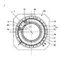
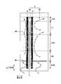
A configuration example of the heat treatment apparatus of the first embodiment will be described. The heat treatment apparatus is a batch-type vertical heat treatment apparatus that performs heat treatment on a large number of substrates at once. FIG. 1 is a vertical cross-sectional view showing a configuration example of a heat treatment apparatus according to a first embodiment. FIG. 2 is a cross-sectional view showing a configuration example of the heat treatment apparatus of the first embodiment.
図1及び図2に示されるように、熱処理装置1は、長手方向が垂直である縦長の処理容器4を有する。処理容器4は、有天井の外管6と、外管6の内側に同心的に配置された円筒体状の内管8と、を有する、二重管構造で構成されている。 As shown in FIGS. 1 and 2, the
外管6及び内管8は、石英、炭化珪素等の耐熱性材料により形成されている。外管6及び内管8は、例えばステンレスにより形成されたマニホールド10によって、下端が保持されている。マニホールド10は、ベースプレート12に固定されている。ただし、マニホールド10を設けることなく、処理容器4全体を、例えば石英によって形成する構成であってもよい。 The
マニホールド10の下端の開口には、例えばステンレス鋼により形成される円盤状のキャップ部14が、シール部材16を介して気密封止可能に取り付けられている。キャップ部14の略中心部には、例えば磁性流体シール18によって気密状態で回転可能な回転軸20が挿通されている。回転軸20の下端は、回転機構22に接続されている。回転軸20の上端には、例えばステンレス鋼により形成されるテーブル24が固定されている。 A disk-
テーブル24上には、例えば石英により形成される保温筒26が設置されている。保温筒26上には、例えば石英により形成されるウエハボート28が載置されている。 A
ウエハボート28には、多数枚(例えば50~150枚)の半導体ウエハ(以下「ウエハW」という。)が、所定の間隔(例えば10mm程度のピッチ)で収容されている。ウエハボート28、保温筒26、テーブル24、及びキャップ部14は、例えばボートエレベータである昇降機構30により、処理容器4内に一体となってロード、アンロードされる。 The
マニホールド10の下部には、処理容器4内に処理ガスを導入するためのガス導入手段32が設けられている。ガス導入手段32は、マニホールド10を気密に貫通するように設けられたガスノズル34を有する。なお、図1では、ガス導入手段32が1つ設けられている場合を示すが、使用するガス種の数等に応じて複数のガス導入手段32が設けられていてもよい。ガスノズル34から処理容器4へと導入されるガスは、流量制御機構(図示せず)により、流量が制御される。 A gas introducing means 32 for introducing a processing gas into the
マニホールド10の上部には、ガス出口36が設けられている。ガス出口36には、排気系38が連結される。排気系38は、ガス出口36に接続された排気通路40と、排気通路40の途中に介設された圧力調整弁42及び真空ポンプ44と、を含む。排気系38により、処理容器4内の圧力を調整しながら排気できる。 A
処理容器4の周囲には、処理容器4を囲むようにしてウエハWを加熱する加熱手段48が設けられている。加熱手段48は、断熱部材50と、保護カバー51と、ヒータエレメント52と、保持部材53と、を有する。 A heating means 48 for heating the wafer W is provided around the
断熱部材50は、天井面を有し、下端が開口した円筒体状に形成されている。断熱部材50の下端は、ベースプレート12に支持されている。断熱部材50は、例えば熱伝導性が低く、柔らかい無定形のシリカ及びアルミナの混合物により形成されている。断熱部材50は、その内周が処理容器4の外面に対して所定の距離だけ離間して配置されている。所定の距離は、例えば62~70mmである。 The
保護カバー51は、断熱部材50の外周の全面を覆うように取り付けられている。保護カバー51は、例えばステンレス鋼により形成されている。 The
ヒータエレメント52は、断熱部材50の内周側に、螺旋状に巻回して配置されている。ヒータエレメント52は、断熱部材50の内面から所定の間隙を隔てた状態で、保持部材53によって、熱膨張及び熱収縮可能に保持されている。ただし、ヒータエレメント52は、保持部材53による保持に代えて、断熱部材50の内周側に螺旋状に溝部を形成し、溝部に嵌めこまれて固定されていてもよい。ヒータエレメント52の材質としては、例えば抵抗発熱体を利用できる。ヒータエレメント52は、電源に接続されており、電力が供給されることで発熱し、ウエハボート28に保持されたウエハWを加熱する。ヒータエレメント52は、上下方向において複数の加熱領域(ゾーン)に区分されている。このようにヒータエレメント52が上下方向において複数の加熱領域に区分されている場合、加熱領域ごとにヒータエレメント52の発熱量を制御することで、処理容器4の上下方向の温度を調節できる。図1の例では、複数の加熱領域は、上方から下方に向かって設けられた、TOP領域、CT領域、CTR領域、CB領域及びBTM領域を含む。なお、ヒータエレメント52は、複数の加熱領域に区分されることなく、単一の加熱領域を形成していてもよい。 The
保持部材53は、断熱部材50の内面に、断熱部材50の軸方向に伸び、かつ、周方向に所定の間隔で設けられている。保持部材53は、ヒータエレメント52を、熱膨張及び熱収縮可能に保持する。 The holding
処理容器4内には、処理容器4の長手方向に沿って温度センサ60が設けられている。温度センサ60は、処理容器4の長手方向に沿って複数の測温部62を有する、例えば熱電対である。図1の例では、CT領域、CTR領域、CB領域及びBTM領域の各々に、測温部62a,62b,62c,62dが配置されている。これにより、CT領域、CTR領域、CB領域及びBTM領域の温度を個別に計測できる。ただし、測温部62の配置はこれに限定されるものではない。また、温度センサ60は、処理容器4と加熱手段48との間の空間Sに設けられていてもよい。 A
処理容器4と加熱手段48との間の空間Sには、図2に示されるように、処理容器4の中心軸Cから外方に伸びて温度センサ60を通る半直線Lを挟み、かつ、処理容器4の長手方向に沿って延びる一対の第1の仕切り70,72が設けられている。第1の仕切り70は、図1に示されるように、上端が温度センサ60の複数の測温部62のうち最上部の測温部62aよりも上方に位置することが好ましい。第1の仕切り72についても、第1の仕切り70と同様に、上端が温度センサ60の複数の測温部62のうち最上部の測温部62aよりも上方に位置することが好ましい。 As shown in FIG. 2, the space S between the
第1の仕切り70,72は、例えばヒータエレメント52又は保持部材53に脱着可能に取り付けられている。ただし、第1の仕切り70,72は、別の部材に取り付けられていてもよい。また、第1の仕切り70,72は、処理容器4の外管6の外面に対して所定の隙間L1を空けて設けられている。所定の隙間L1は、例えば7~15mmである。 The
第1の仕切り70,72は、例えばアルミナ(Al2O3)や窒化アルミニウム(AlN)等のセラミックス材料により形成されている。第1の仕切り70,72は、それぞれブロック状に成形されたセラミックス成形部材であってもよく、アルミナクロス等の繊維状の部材であってもよい。また、これらを組み合わせた部材であってもよい。このように、第1の仕切り70,72は、単一の部材により形成されていてもよく、複数に分割可能な部材により形成されていてもよい。The
処理容器4と加熱手段48との間の空間Sには、図2に示されるように、一方の第1の仕切り70から他方の第1の仕切り72まで処理容器4の周方向に沿って延びる、半円以上の円弧板状の第2の仕切り80が設けられている。すなわち、第2の仕切り80は、処理容器4の中心軸Cから外方に伸びて温度センサ60を通る半直線Lを通らないように設けられている。 In the space S between the
第2の仕切り80は、例えばヒータエレメント52又は保持部材53に脱着可能に取り付けられている。ただし、第2の仕切り80は、別の部材、例えば第1の仕切り70,72に取り付けられていてもよい。また、第2の仕切り80は、処理容器4の外管6の外面に対して所定の隙間L2を空けて設けられている。所定の隙間L2は、例えば7~15mmである。 The
第2の仕切り80は、例えば図1に示されるように、複数の加熱領域のうち最下部の加熱領域であるBTM領域と、BTM領域の上方に隣接するCB領域との境界又は該境界の近傍に設けられている。なお、BTM領域とCB領域との境界の近傍とは、BTM領域の上下方向における中間位置よりもCB領域側の範囲、及びCB領域の上下方向における中間位置よりもBTM領域側の範囲を意味する。 The
また、第2の仕切り80は、複数の加熱領域の各境界又は該境界の近傍に対応させて複数設けられていてもよい。この場合、第2の仕切り80は、隣接する2つの加熱領域の境界又は該境界の近傍のいずれか1箇所に設けられていてもよく、複数箇所に設けられていてもよい。 Also, a plurality of
第2の仕切り80は、例えばアルミナ(Al2O3)や窒化アルミニウム(AlN)等のセラミックス材料により形成されている。第2の仕切り80は、それぞれブロック状に成形された成形部材であってもよく、アルミナクロス等の繊維状の部材であってもよい。また、これらを組み合わせた部材であってもよい。このように、第2の仕切り80は、単一の部材により形成されていてもよく、複数に分割可能な部材により形成されていてもよい。なお、第2の仕切り80は、設けられていなくてもよい。The
(効果)
第1の実施形態の熱処理装置1により奏される効果について説明する。(effect)
Effects achieved by the
まず、従来の熱処理装置について説明する。従来の熱処理装置は、図1の熱処理装置1における、第1の仕切り70,72及び第2の仕切り80が設けられていない装置である。なお、その他の構成については、熱処理装置1と同様である。図3は、従来の熱処理装置の処理容器4と加熱手段48との間の空間Sに生じる対流を説明する図であり、処理容器4の中心軸Cから空間Sの方向を見たときの概略図である。また、図3中、対流を一点鎖線の矢印で示す。 First, a conventional heat treatment apparatus will be described. A conventional heat treatment apparatus is an apparatus in which the
図3に示されるように、従来の熱処理装置では、空間S内に、処理容器4の周方向に沿って蛇行しながら上下方向に流れる対流が発生していた。このため、この対流に起因して処理容器4の断面方向や高さ方向の均熱性が悪化し、熱処理の面内均一性や面間均一性が劣化するという課題があった。また、この対流は、ウエハを熱処理するごと(ランごと)に異なった態様を示すことがあり、ランごとの熱処理の態様が異なり、熱処理の再現性が低下していた。 As shown in FIG. 3 , in the conventional heat treatment apparatus, convection flows in the vertical direction while meandering in the space S along the circumferential direction of the
特に、ウエハボート28の下部を支持する保温筒26近傍の温度が比較的低くなる傾向にあり、また、処理容器4の下方に位置するウエハ移載用の空間であるローディングエリアの雰囲気温度が比較的低い。そのため、均熱性を確保するために処理容器4の下部に位置する加熱領域であるBTM領域のヒータには、他の加熱領域のヒータよりも多くの電力を投入する。その結果、BTM領域のヒータ自体は他の加熱領域のヒータ自体よりも高温になるため、上記の対流は空間SのBTM領域において発生しやすい。 In particular, the temperature in the vicinity of the
次に、熱処理装置1について説明する。図4は、図1の熱処理装置1の処理容器4と加熱手段48との間の空間Sに生じる対流を説明する図であり、処理容器4の中心軸Cから空間Sの方向を見たときの概略図である。また、図4中、対流を一点鎖線の矢印で示す。 Next, the
前述したように、熱処理装置1では、空間Sに、処理容器4の中心軸Cから伸びて温度センサ60を通る半直線Lを挟んで設けられ、処理容器4の長手方向に沿って伸びる一対の第1の仕切り70,72が設けられている。これにより、図4に示されるように、第1の仕切り70,72によって、空間Sが、温度センサ60が設けられている位置と対応する第1の空間S1と、該第1の空間S1を除く第2の空間S2とに区画される。このため、第2の空間S2においてランごとに対流に変化が生じた場合であっても、第1の空間S1には対流の変化の影響が及びにくい。その結果、ランごとの熱処理の態様が略同一となり、熱処理の再現性が向上する。 As described above, in the
また、熱処理装置1では、空間SにおけるBTM領域とCB領域との境界に、一方の第1の仕切り70から他方の第1の仕切り72まで処理容器4の周方向に沿って延びる、半円以上の円弧板状の第2の仕切り80が設けられている。これにより、図4に示されるように、BTM領域で発生する対流がBTM領域よりも上方の領域であるCB領域、CTR領域、CT領域及びTOP領域に伝わることを抑制できる。このため、BTM領域においてラン間で対流に変化が生じた場合であっても、CB領域、CTR領域、CT領域及びTOP領域には対流の変化の影響が及びにくい。その結果、ランごとの熱処理の態様が略同一となり、熱処理の再現性が向上する。 Further, in the
〔第2の実施形態〕
(熱処理装置)
第2の実施形態の熱処理装置の構成例について説明する。図5は、第2の実施形態の熱処理装置の構成例を示す横断面図である。[Second embodiment]
(heat treatment equipment)
A configuration example of the heat treatment apparatus of the second embodiment will be described. FIG. 5 is a cross-sectional view showing a configuration example of a heat treatment apparatus according to the second embodiment.
図5に示されるように、第2の実施形態の熱処理装置1Aは、第2の仕切り80が、第1の部位80aと、第2の部位80bと、を含む。 As shown in FIG. 5, in a
第1の部位80aは、一方の第1の仕切り70から他方の第1の仕切り72まで処理容器4の周方向に沿って延びる、半円以上の円弧板状の部位である。すなわち、第1の部位80aは、処理容器4の中心軸Cから外方に伸びて温度センサ60を通る半直線Lを通らないように設けられている。 The
第2の部位80bは、一方の第1の仕切り70から他方の第1の仕切り72まで処理容器4の周方向に沿って延びる、半円未満の円弧板状の部位である。すなわち、第2の部位80bは、処理容器4の中心軸Cから外方に伸びて温度センサ60を通る半直線Lを通るように設けられている。 The
なお、その他の構成については、第1の実施形態の熱処理装置1と同様の構成である。 Other configurations are the same as those of the
(効果)
第2の実施形態の熱処理装置1Aにより奏される効果について説明する。図6は、図5の熱処理装置1Aの処理容器4と加熱手段48との間の空間Sに生じる対流を説明する図であり、処理容器4の中心軸Cから空間Sの方向を見たときの概略図である。また、図6中、対流を一点鎖線の矢印で示す。(effect)
Effects produced by the
前述したように、熱処理装置1Aでは、空間Sに、処理容器4の中心軸Cから伸びて温度センサ60を通る半直線Lを挟んで設けられ、処理容器4の長手方向に沿って伸びる一対の第1の仕切り70,72が設けられている。これにより、図6に示されるように、第1の仕切り70,72によって、空間Sが、温度センサ60が設けられている位置と対応する第1の空間S1と、該第1の空間S1を除く第2の空間S2とに区画される。このため、第2の空間S2においてランごとに対流に変化が生じた場合であっても、第1の空間S1には対流の変化の影響が及びにくい。その結果、ランごとの熱処理の態様が略同一となり、熱処理の再現性が向上する。 As described above, in the
また、熱処理装置1Aでは、空間SにおけるBTM領域とCB領域との境界に、一方の第1の仕切り70から他方の第1の仕切り72まで処理容器4の周方向に沿って延びる円弧板状の第1の部位80a、第2の部位80bを含む第2の仕切り80が設けられている。これにより、図6に示されるように、BTM領域で発生する対流がBTM領域よりも上方の領域であるCB領域、CTR領域、CT領域及びTOP領域に伝わることを抑制できる。このため、BTM領域においてラン間で対流に変化が生じた場合であっても、CB領域、CTR領域、CT領域及びTOP領域には対流の変化の影響が及びにくい。その結果、ランごとの熱処理の態様が略同一となり、熱処理の再現性が向上する。 Further, in the
〔第3の実施形態〕
(熱処理装置)
第3の実施形態の熱処理装置の構成例について説明する。図7は、第3の実施形態の熱処理装置の構成例を示す横断面図である。[Third Embodiment]
(heat treatment equipment)
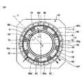
A configuration example of the heat treatment apparatus of the third embodiment will be described. FIG. 7 is a cross-sectional view showing a configuration example of a heat treatment apparatus according to the third embodiment.
図7に示されるように、第3の実施形態の熱処理装置1Bは、一対の第1の仕切り70,72と同一円周上に、一対の第1の仕切り70,72と間隔をおいて設けられ、処理容器4の長手方向に沿って伸びる一又は複数の第3の仕切り90を有する。なお、図7では、一例として第3の仕切り90が6つ設けられている場合を示す。 As shown in FIG. 7, the
第2の仕切り80は、一対の第1の仕切り70,72及び複数の第3の仕切り90を接続するように処理容器4の周方向に沿って延びる複数の円弧板状の部位80c,80d,80e,80f,80g,80h,80i,80jを含む。円弧板状の部位80cは、第1の仕切り70と該第1の仕切り70と隣接する第3の仕切り90とを接続するように設けられている。円弧板状の部位80d,80e,80f,80g,80hは、隣接する第3の仕切り90を接続するように設けられている。円弧板状の部位80iは、第1の仕切り72と該第1の仕切り72と隣接する第3の仕切り90とを接続するように設けられている。円弧板状の部位80jは、第1の仕切り70と第1の仕切り72とを接続するように設けられている。 The
なお、その他の構成については、第1の実施形態の熱処理装置1と同様の構成である。 Other configurations are the same as those of the
(効果)
第3の実施形態の熱処理装置1Bにより奏される効果について説明する。図8は、図7の熱処理装置1Bの処理容器4と加熱手段48との間の空間Sに生じる対流を説明する図であり、処理容器4の中心軸Cから空間Sの方向を見たときの概略図である。また、図8中、対流を一点鎖線の矢印で示す。(effect)
Effects produced by the
前述したように、熱処理装置1Bでは、空間Sに、処理容器4の中心軸Cから伸びて温度センサ60を通る半直線Lを挟んで設けられ、処理容器4の長手方向に沿って伸びる一対の第1の仕切り70,72が設けられている。これにより、図8に示されるように、第1の仕切り70,72によって、空間Sが、温度センサ60が設けられている位置と対応する第1の空間S1と、該第1の空間S1を除く第2の空間S2とに区画される。このため、第2の空間S2においてランごとに対流に変化が生じた場合であっても、第1の空間S1には対流の変化の影響が及びにくい。その結果、ランごとの熱処理の態様が略同一となり、熱処理の再現性が向上する。 As described above, in the
また、熱処理装置1Bは、一対の第1の仕切り70,72と同一円周上に、一対の第1の仕切り70,72と間隔をおいて設けられ、処理容器4の長手方向に沿って伸びる複数の第3の仕切り90を有する。これにより、空間Sにおける処理容器4の周方向に生じる温度分布を選択的に区分けできる。このため、処理容器4の周方向の温度分布の違いにより生じる周方向の対流を抑制することができる。その結果、ランごとの熱処理の態様が略同一となり、熱処理の再現性が向上する。 Further, the
また、熱処理装置1Bでは、空間SにおけるBTM領域とCB領域との境界に、一対の第1の仕切り70,72及び複数の第3の仕切り90を接続する複数の円弧板状の部位80c~80jを含む第2の仕切り80が設けられている。これにより、図8に示されるように、BTM領域で発生する対流がBTM領域よりも上方の領域であるCB領域、CTR領域、CT領域及びTOP領域に伝わることを抑制できる。このため、BTM領域においてラン間で対流に変化が生じた場合であっても、CB領域、CTR領域、CT領域及びTOP領域には対流の変化の影響が及びにくい。その結果、ランごとの熱処理の態様が略同一となり、熱処理の再現性が向上する。 Further, in the
〔実施例〕
次に、熱処理装置1により奏される効果を確認した実施例について説明する。〔Example〕
Next, an example will be described in which the effects of the
(実施例1)
実施例1では、一定温度で実行される第1の熱処理を20ラン繰り返し実行したときの温度変動について評価した。実施例1では、熱処理装置として、第1の仕切り70,72及び第2の仕切り80を有していない熱処理装置、第1の仕切り70,72を有する熱処理装置、及び第1の仕切り70,72及び第2の仕切り80を有する熱処理装置を用いた。(Example 1)
In Example 1, the temperature fluctuation was evaluated when the first heat treatment performed at a constant temperature was repeatedly performed for 20 runs. In Example 1, the heat treatment apparatus includes a heat treatment apparatus without the
図9は、一定温度で実行される第1の熱処理の設定温度の時間変化を示す図である。図9中、時間を横軸に示し、温度[℃]を縦軸に示す。図9に示されるように、実施例1では、処理容器4内にウエハWを搬入する搬入ステップ、ウエハWに成膜を行う第1成膜ステップ、第2成膜ステップ及びウエハWを処理容器4内から搬出する搬出ステップにおいて設定温度を500℃に設定した。 FIG. 9 is a diagram showing temporal changes in the set temperature of the first heat treatment performed at a constant temperature. In FIG. 9, the horizontal axis indicates time, and the vertical axis indicates temperature [°C]. As shown in FIG. 9, in the first embodiment, a carrying-in step of carrying a wafer W into the
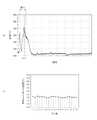
図10は、従来の熱処理装置による第1の熱処理の温度再現性を示す図である。図10(a)は、空間SのCB領域における測定温度の時間変化を示すグラフであり、時間を横軸に示し、温度[℃]を縦軸に示す。図10(b)は、図10(a)の時刻tm1における測定温度のランごとの変化を示すグラフであり、ラン数を横軸に示し、時刻tm1における温度[℃]を縦軸に示す。また、図10(a)中の複数の実線はランごとの結果を示す。 FIG. 10 is a diagram showing temperature reproducibility of the first heat treatment by a conventional heat treatment apparatus. FIG. 10(a) is a graph showing temporal changes in the measured temperature in the CB region of the space S, where the horizontal axis indicates time and the vertical axis indicates temperature [° C.]. FIG. 10(b) is a graph showing changes in the measured temperature at time tm1 in FIG. 10(a) for each run, where the horizontal axis indicates the number of runs and the vertical axis indicates the temperature [° C.] at time tm1. A plurality of solid lines in FIG. 10(a) indicate the results for each run.
図10(a)に示されるように、従来の熱処理装置を用いて第1の熱処理を実行した場合、搬入ステップにおけるランごとの温度に変動が生じていることが分かる。また、図10(b)に示されるように、従来の熱処理装置を用いて第1の熱処理を実行した場合、時刻tm1における温度がランごとに少しずつ変動し、特に第11ランにおける温度が大きく変動していることが分かる。 As shown in FIG. 10(a), when the conventional heat treatment apparatus is used to perform the first heat treatment, it can be seen that the temperature fluctuates for each run in the loading step. Further, as shown in FIG. 10B, when the conventional heat treatment apparatus is used to perform the first heat treatment, the temperature at time tm1 varies little by run, and the temperature in the 11th run is particularly large. I know it's changing.
図11は、第1の仕切り70,72を有する熱処理装置による第1の熱処理の温度再現性を示す図である。図11(a)は、空間SのCB領域における測定温度の時間変化を示すグラフであり、時間を横軸に示し、温度[℃]を縦軸に示す。図11(b)は、図11(a)の時刻tm1における測定温度のランごとの変化を示すグラフであり、ラン数を横軸に示し、時刻tm1における温度[℃]を縦軸に示す。また、図11(a)中の複数の実線はランごとの結果を示す。 FIG. 11 is a diagram showing temperature reproducibility of the first heat treatment by the heat treatment apparatus having the
図11(a)及び図11(b)に示されるように、第1の仕切り70,72を有する熱処理装置を用いて第1の熱処理を実行した場合、搬入ステップにおけるランごとの温度にほとんど変動がないことが分かる。一方、図11(a)に示されるように、搬入工程の後に、ランごとの温度に僅かな変動が生じていることが分かる(破線で示す丸印を参照)。 As shown in FIGS. 11( a ) and 11 ( b ), when the first heat treatment is performed using the heat treatment apparatus having the
図12は、第1の仕切り70,72及び第2の仕切り80を有する熱処理装置による第1の熱処理の温度再現性を示す図である。図12(a)は、空間SのCB領域における測定温度の時間変化を示すグラフであり、時間を横軸、温度[℃]を縦軸に示す。図12(b)は、図12(a)の時刻tm1における測定温度のランごとの変化を示すグラフであり、ラン数を横軸に示し、時刻tm1における温度[℃]を縦軸に示す。また、図12(a)中の複数の実線はランごとの結果を示す。 FIG. 12 is a diagram showing temperature reproducibility of the first heat treatment by the heat treatment apparatus having the
図12(a)及び図12(b)に示されるように、第1の仕切り70,72及び第2の仕切り80を有する熱処理装置を用いて第1の熱処理を実行した場合、全てのステップにおいて、ランごとの温度変動がほとんどないことが分かる。 As shown in FIGS. 12(a) and 12(b), when the first heat treatment is performed using the heat treatment apparatus having the
以上の結果から、空間Sに第1の仕切り70,72を設けることにより、一定温度で実行される第1の熱処理において、搬入ステップでの温度再現性を向上させることができると言える。また、空間Sに第1の仕切り70,72に加えて、第2の仕切り80を設けることにより、一定温度で実行される第1の熱処理において、全てのステップでの温度再現性を向上させることができると言える。 From the above results, it can be said that by providing the
(実施例2)
実施例2では、温度の変更を伴う第2の熱処理を20ラン繰り返し実行したときの温度変動について評価した。実施例2では、熱処理装置として、第1の仕切り70,72及び第2の仕切り80を有していない熱処理装置、第1の仕切り70,72を有する熱処理装置、及び第1の仕切り70,72及び第2の仕切り80を有する熱処理装置を用いた。(Example 2)
In Example 2, the temperature fluctuation was evaluated when the second heat treatment accompanied by the change in temperature was repeatedly performed for 20 runs. In Example 2, the heat treatment apparatus includes a heat treatment apparatus without the
図13は、温度の変更を伴う第2の熱処理の設定温度の時間変化を示す図である。図13中、時間を横軸に示し、温度[℃]を縦軸に示す。図13に示されるように、実施例2では、処理容器4内にウエハWを搬入する搬入ステップにおける設定温度を400℃に設定した。また、ウエハWに成膜を行う第1成膜ステップにおける設定温度を500℃に設定した。また、ウエハWに成膜を行う第2成膜ステップにおける設定温度を630℃に設定した。また、ウエハWを処理容器4内から搬出する搬出ステップにおける設定温度を400℃に設定した。 FIG. 13 is a diagram showing the change over time of the set temperature of the second heat treatment that accompanies temperature changes. In FIG. 13, the horizontal axis indicates time, and the vertical axis indicates temperature [°C]. As shown in FIG. 13, in Example 2, the set temperature in the loading step of loading the wafer W into the
図14は、従来の熱処理装置による第2の熱処理の温度再現性を示す図である。図14(a)は、空間SのCB領域における測定温度の時間変化を示すグラフであり、時間を横軸に示し、温度[℃]を縦軸に示す。図14(b)は、図14(a)の時刻tm2における測定温度のランごとの変化を示すグラフであり、ラン数を横軸に示し、時刻tm2における温度[℃]を縦軸に示す。また、図14(a)中の複数の実線はランごとの結果を示す。 FIG. 14 is a diagram showing temperature reproducibility of the second heat treatment by a conventional heat treatment apparatus. FIG. 14(a) is a graph showing temporal changes in the measured temperature in the CB region of the space S, where the horizontal axis indicates time and the vertical axis indicates temperature [° C.]. FIG. 14(b) is a graph showing changes in the measured temperature at time tm2 in FIG. 14(a) for each run, where the horizontal axis indicates the number of runs and the vertical axis indicates the temperature [° C.] at time tm2. A plurality of solid lines in FIG. 14(a) indicate the results for each run.
図14(a)に示されるように、従来の熱処理装置を用いて第2の熱処理を実行した場合、第1成膜ステップ、第2成膜ステップを含む全てのステップにおいて、ランごとの温度に変動が生じていることが分かる。また、図14(b)に示されるように、従来の熱処理装置を用いて第2の熱処理を実行した場合、第1成膜ステップの前の昇温直後の時刻tm2における温度がランごとに大きく変動し、熱処理の温度再現性が悪いことが分かる。 As shown in FIG. 14(a), when the second heat treatment is performed using the conventional heat treatment apparatus, in all steps including the first film formation step and the second film formation step, the temperature for each run is It can be seen that changes have occurred. Further, as shown in FIG. 14B, when the second heat treatment is performed using the conventional heat treatment apparatus, the temperature at time tm2 immediately after the temperature rise before the first film formation step increases for each run. It can be seen that the temperature reproducibility of the heat treatment is poor.
図15は、第1の仕切り70,72を有する熱処理装置による第2の熱処理の温度再現性を示す図である。図15(a)は、空間SのCB領域における測定温度の時間変化を示すグラフであり、時間を横軸に示し、温度[℃]を縦軸に示す。図15(b)は、図15(a)の時刻tm2における測定温度のランごとの変化を示すグラフであり、ラン数を横軸に示し、時刻tm2における温度[℃]を縦軸に示す。また、図15(a)中の複数の実線はランごとの結果を示す。 FIG. 15 is a diagram showing the temperature reproducibility of the second heat treatment by the heat treatment apparatus having the
図15(a)及び図15(b)に示されるように、第1の仕切り70,72を有する熱処理装置を用いて第2の熱処理を実行した場合、全てのステップにおいて、ランごとの温度変動が従来の熱処理装置を用いた場合よりも小さくなっていることが分かる。 As shown in FIGS. 15( a ) and 15 ( b ), when the second heat treatment is performed using the heat treatment apparatus having the
図16は、第1の仕切り70,72及び第2の仕切り80を有する熱処理装置による第2の熱処理の温度再現性を示す図である。図16(a)は、空間SのCB領域における測定温度の時間変化を示すグラフであり、時間を横軸、温度[℃]を縦軸に示す。図16(b)は、図16(a)の時刻tm2における測定温度のランごとの変化を示すグラフであり、ラン数を横軸に示し、時刻tm2における温度[℃]を縦軸に示す。また、図16(a)中の複数の実線はランごとの結果を示す。 FIG. 16 is a diagram showing temperature reproducibility of the second heat treatment by the heat treatment apparatus having the
図16(a)及び図16(b)に示されるように、第1の仕切り70,72及び第2の仕切り80を有する熱処理装置を用いて第2の熱処理を実行した場合、全てのステップにおいて、ランごとの温度変動がほとんどないことが分かる。 As shown in FIGS. 16(a) and 16(b), when the second heat treatment is performed using the heat treatment apparatus having the
以上の結果から、空間Sに第1の仕切り70,72を設けることにより、温度の変更を伴う第2の熱処理の際の温度再現性を向上させることができると言える。また、空間Sに第1の仕切り70,72に加えて、第2の仕切り80を設けることにより、温度の変更を伴う第2の熱処理の際の温度再現性がより向上させることができると言える。 From the above results, it can be said that the provision of the
今回開示された実施形態はすべての点で例示であって制限的なものではないと考えられるべきである。上記の実施形態は、添付の請求の範囲及びその趣旨を逸脱することなく、様々な形態で省略、置換、変更されてもよい。 It should be considered that the embodiments disclosed this time are illustrative in all respects and not restrictive. The above-described embodiments may be omitted, substituted or modified in various ways without departing from the scope and spirit of the appended claims.
1 熱処理装置
4 処理容器
48 加熱手段
50 断熱部材
52 ヒータエレメント
53 保持部材
60 温度センサ
62 測温部
70,72 第1の仕切り
80 第2の仕切り
90 第3の仕切り
S 空間1
Claims (15)
Translated fromJapanese前記処理容器の周囲に設けられた加熱手段と、
前記処理容器内又は前記処理容器と前記加熱手段との間の空間に前記処理容器の長手方向に沿って設けられた温度センサと、
前記空間に、前記処理容器の中心軸から伸びて前記温度センサを通る半直線を挟んで設けられ、前記処理容器の長手方向に沿って伸びる一対の仕切りと、
を有し、
前記加熱手段は、
前記処理容器の外周を覆う断熱部材と、
前記断熱部材の内側に設けられるヒータエレメントと、
前記断熱部材の内面に取り付けられ、前記ヒータエレメントを保持する保持部材と、
を有し、
前記仕切りは、前記ヒータエレメント又は前記保持部材に脱着可能に取り付けられている、
熱処理装置。a vertically long processing container;
heating means provided around the processing vessel;
a temperature sensor provided along the longitudinal direction of the processing container in the processing container or in the space between the processing container and the heating means;
a pair of partitions provided in the space across a half line extending from the center axis of the processing container and passing through the temperature sensor and extending along the longitudinal direction of the processing container;
has
The heating means
a heat insulating member covering the outer periphery of the processing container;
a heater element provided inside the heat insulating member;
a holding member that is attached to the inner surface of the heat insulating member and holds the heater element;
has
The partition is detachably attached to the heater element or the holding member,
Heat treatment equipment.
前記仕切りは、上端が前記複数の測温部のうち最上部の測温部よりも上方に位置する、
請求項1に記載の熱処理装置。The temperature sensor has a plurality of temperature measuring parts along the longitudinal direction of the processing container,
An upper end of the partition is located above an uppermost temperature measuring portion among the plurality of temperature measuring portions,
The heat treatment apparatus according to claim 1.
請求項1又は2に記載の熱処理装置。The partition can be divided into a plurality of
The heat treatment apparatus according to claim 1 or 2.
請求項1乃至3のいずれか一項に記載の熱処理装置。The partition is provided with a gap from the outer surface of the processing container,
The heat treatment apparatus according to any one of claims 1 to3 .
請求項1乃至4のいずれか一項に記載の熱処理装置。The partition is made of a ceramic material,
The heat treatment apparatus according to any one of claims 1 to4 .
請求項1乃至5のいずれか一項に記載の熱処理装置。A second partition provided in the space and extending along the circumferential direction of the processing container,
The heat treatment apparatus according to any one of claims 1 to5 .
請求項6に記載の熱処理装置。The second partition includes an arc plate-shaped portion of a semicircle or more extending along the circumferential direction of the processing container from one side of the partition to the other side,
The heat treatment apparatus according to claim6 .
請求項7に記載の熱処理装置。The second partition includes an arc plate-shaped portion less than a semicircle extending along the circumferential direction of the processing container from one side of the partition to the other side,
The heat treatment apparatus according to claim7 .
前記第2の仕切りは、前記一対の仕切り及び前記第3の仕切りを接続するように前記処理容器の周方向に沿って延びる複数の円弧板状の部位を含む、
請求項6に記載の熱処理装置。one or more third partitions provided on the same circumference as the pair of partitions and spaced apart from the pair of partitions and extending along the longitudinal direction of the processing container;
The second partition includes a plurality of arc plate-shaped portions extending along the circumferential direction of the processing container so as to connect the pair of partitions and the third partition,
The heat treatment apparatus according to claim6 .
前記第2の仕切りは、前記複数の加熱領域のうち最下部の加熱領域と前記最下部の加熱領域の上方に隣接する加熱領域との境界又は該境界の近傍に設けられている、
請求項6乃至9のいずれか一項に記載の熱処理装置。The heating means is divided into a plurality of individually controllable heating regions in the longitudinal direction of the processing vessel,
The second partition is provided at or near a boundary between a lowermost heating region and a heating region adjacent above the lowermost heating region among the plurality of heating regions,
The heat treatment apparatus according to any one of claims6 to9 .
前記第2の仕切りは、前記複数の加熱領域の各境界又は該境界の近傍に対応させて複数設けられている、
請求項6乃至9のいずれか一項に記載の熱処理装置。The heating means is divided into a plurality of individually controllable heating regions in the longitudinal direction of the processing vessel,
A plurality of the second partitions are provided corresponding to each boundary of the plurality of heating regions or the vicinity of the boundary,
The heat treatment apparatus according to any one of claims6 to9 .
請求項6乃至11のいずれか一項に記載の熱処理装置。The second partition can be divided into a plurality,
The heat treatment apparatus according to any one of claims6 to11 .
請求項6乃至12のいずれか一項に記載の熱処理装置。The second partition is detachably attached to the heater element or the holding member,
The heat treatment apparatus according to any one of claims6 to12 .
請求項6乃至13のいずれか一項に記載の熱処理装置。The second partition is provided with a gap from the outer surface of the processing container,
The heat treatment apparatus according to any one of claims6 to13 .
請求項6乃至14のいずれか一項に記載の熱処理装置。The second partition is made of a ceramic material,
The heat treatment apparatus according to any one of claims6 to14 .
Priority Applications (5)
| Application Number | Priority Date | Filing Date | Title |
|---|---|---|---|
| JP2018235169AJP7203588B2 (en) | 2018-12-17 | 2018-12-17 | Heat treatment equipment |
| TW108144669ATWI784215B (en) | 2018-12-17 | 2019-12-06 | Heat treatment device |
| CN201911248706.9ACN111326446B (en) | 2018-12-17 | 2019-12-09 | Heat treatment device |
| KR1020190164767AKR102581140B1 (en) | 2018-12-17 | 2019-12-11 | Heat treatment apparatus |
| US16/711,527US11234296B2 (en) | 2018-12-17 | 2019-12-12 | Heat treatment apparatus |
Applications Claiming Priority (1)
| Application Number | Priority Date | Filing Date | Title |
|---|---|---|---|
| JP2018235169AJP7203588B2 (en) | 2018-12-17 | 2018-12-17 | Heat treatment equipment |
Publications (2)
| Publication Number | Publication Date |
|---|---|
| JP2020098808A JP2020098808A (en) | 2020-06-25 |
| JP7203588B2true JP7203588B2 (en) | 2023-01-13 |
Family
ID=71072026
Family Applications (1)
| Application Number | Title | Priority Date | Filing Date |
|---|---|---|---|
| JP2018235169AActiveJP7203588B2 (en) | 2018-12-17 | 2018-12-17 | Heat treatment equipment |
Country Status (5)
| Country | Link |
|---|---|
| US (1) | US11234296B2 (en) |
| JP (1) | JP7203588B2 (en) |
| KR (1) | KR102581140B1 (en) |
| CN (1) | CN111326446B (en) |
| TW (1) | TWI784215B (en) |
Families Citing this family (2)
| Publication number | Priority date | Publication date | Assignee | Title |
|---|---|---|---|---|
| US11703229B2 (en)* | 2018-12-05 | 2023-07-18 | Yi-Ming Hung | Temperature adjustment apparatus for high temperature oven |
| JP7658672B2 (en) | 2021-06-08 | 2025-04-08 | 東京エレクトロン株式会社 | Heat Treatment Equipment |
Citations (4)
| Publication number | Priority date | Publication date | Assignee | Title |
|---|---|---|---|---|
| JP2001144023A (en) | 1999-11-18 | 2001-05-25 | Tokyo Electron Ltd | Vertical heat treatment device |
| JP2003282578A (en) | 2002-03-26 | 2003-10-03 | Hitachi Kokusai Electric Inc | Heat treatment apparatus and semiconductor manufacturing method |
| JP2009004715A (en) | 2007-06-25 | 2009-01-08 | Hitachi Kokusai Electric Inc | Substrate processing apparatus and heating apparatus used therefor |
| JP2014096453A (en) | 2012-11-08 | 2014-05-22 | Tokyo Electron Ltd | Heat treatment apparatus |
Family Cites Families (18)
| Publication number | Priority date | Publication date | Assignee | Title |
|---|---|---|---|---|
| JPH0677196A (en)* | 1992-08-24 | 1994-03-18 | Fujitsu Ltd | Divided batch-type heat treatment apparatus |
| JPH0897167A (en)* | 1994-09-28 | 1996-04-12 | Tokyo Electron Ltd | Processing system and heat-treatment system |
| JP3641193B2 (en)* | 2000-06-30 | 2005-04-20 | 東京エレクトロン株式会社 | Vertical heat treatment apparatus, heat treatment method, and heat insulation unit |
| JP3912208B2 (en)* | 2002-02-28 | 2007-05-09 | 東京エレクトロン株式会社 | Heat treatment equipment |
| KR100395662B1 (en)* | 2002-03-21 | 2003-08-25 | 코닉 시스템 주식회사 | Rotation type Rapid Thermal Process Apparatus for enhanced temperature uniformity |
| WO2004007800A1 (en)* | 2002-07-15 | 2004-01-22 | Aviza Technology, Inc. | Thermal processing apparatus and method for evacuating a process chamber |
| JP4683332B2 (en)* | 2005-12-28 | 2011-05-18 | 株式会社Ihi | Heat treatment equipment |
| US8222574B2 (en)* | 2007-01-15 | 2012-07-17 | Applied Materials, Inc. | Temperature measurement and control of wafer support in thermal processing chamber |
| US8023806B2 (en)* | 2007-03-20 | 2011-09-20 | Tokyo Electron Limited | Heat processing furnace and vertical-type heat processing apparatus |
| JP4959733B2 (en)* | 2008-02-01 | 2012-06-27 | 東京エレクトロン株式会社 | Thin film forming method, thin film forming apparatus, and program |
| JP5751549B2 (en)* | 2010-03-15 | 2015-07-22 | 株式会社日立国際電気 | Heat treatment apparatus and semiconductor manufacturing method |
| JP5868619B2 (en)* | 2011-06-21 | 2016-02-24 | ニチアス株式会社 | Heat treatment furnace and heat treatment apparatus |
| KR101390510B1 (en)* | 2012-07-05 | 2014-04-30 | 주식회사 나래나노텍 | Heating Structure for Heat Treatment Chamber of Substrates and Heat Treatment Chamber of Substrates Having the Same |
| JP2014082014A (en) | 2012-10-12 | 2014-05-08 | Tokyo Electron Ltd | Heater device and heat treatment device |
| WO2015037748A1 (en)* | 2013-09-10 | 2015-03-19 | 주식회사 테라세미콘 | Heat treatment device and heat treatment system comprising same |
| JP6255267B2 (en)* | 2014-02-06 | 2017-12-27 | 株式会社日立国際電気 | Substrate processing apparatus, heating apparatus, ceiling insulator, and semiconductor device manufacturing method |
| KR20150145557A (en)* | 2014-06-20 | 2015-12-30 | (주)이노시티 | Vertical type heat treatment apparatus |
| US11043402B2 (en)* | 2017-09-12 | 2021-06-22 | Kokusai Electric Corporation | Cooling unit, heat insulating structure, and substrate processing apparatus |
- 2018
- 2018-12-17JPJP2018235169Apatent/JP7203588B2/enactiveActive
- 2019
- 2019-12-06TWTW108144669Apatent/TWI784215B/enactive
- 2019-12-09CNCN201911248706.9Apatent/CN111326446B/enactiveActive
- 2019-12-11KRKR1020190164767Apatent/KR102581140B1/enactiveActive
- 2019-12-12USUS16/711,527patent/US11234296B2/enactiveActive
Patent Citations (4)
| Publication number | Priority date | Publication date | Assignee | Title |
|---|---|---|---|---|
| JP2001144023A (en) | 1999-11-18 | 2001-05-25 | Tokyo Electron Ltd | Vertical heat treatment device |
| JP2003282578A (en) | 2002-03-26 | 2003-10-03 | Hitachi Kokusai Electric Inc | Heat treatment apparatus and semiconductor manufacturing method |
| JP2009004715A (en) | 2007-06-25 | 2009-01-08 | Hitachi Kokusai Electric Inc | Substrate processing apparatus and heating apparatus used therefor |
| JP2014096453A (en) | 2012-11-08 | 2014-05-22 | Tokyo Electron Ltd | Heat treatment apparatus |
Also Published As
| Publication number | Publication date |
|---|---|
| TW202032668A (en) | 2020-09-01 |
| US11234296B2 (en) | 2022-01-25 |
| TWI784215B (en) | 2022-11-21 |
| CN111326446B (en) | 2024-06-28 |
| JP2020098808A (en) | 2020-06-25 |
| US20200196390A1 (en) | 2020-06-18 |
| KR20200074875A (en) | 2020-06-25 |
| KR102581140B1 (en) | 2023-09-20 |
| CN111326446A (en) | 2020-06-23 |
Similar Documents
| Publication | Publication Date | Title |
|---|---|---|
| CN106469666B (en) | Base and substrate processing equipment | |
| US11021794B2 (en) | Graphite susceptor | |
| EP1182692B1 (en) | Heat-processing apparatus and method for semiconductor processing | |
| US7311520B2 (en) | Heat treatment apparatus | |
| KR101046043B1 (en) | Furnace multi-zone heater | |
| US9194044B2 (en) | Deposition apparatus and method | |
| JP3471100B2 (en) | Vertical heat treatment equipment | |
| US10340151B2 (en) | Substrate processing apparatus, heating apparatus, ceiling heat insulator, and method of manufacturing semiconductor device | |
| JPH0583172B2 (en) | ||
| JP7203588B2 (en) | Heat treatment equipment | |
| US9957616B2 (en) | Substrate processing apparatus and heating unit | |
| US20080197125A1 (en) | Substrate heating method and apparatus | |
| TWI550681B (en) | Heat treatment apparatus and method of controlling the same | |
| TW201944855A (en) | An advanced ceramic lid with embedded heater elements and embedded RF coil for HDP CVD and inductively coupled plasma treatment chambers | |
| JP7122856B2 (en) | Heat treatment equipment | |
| CN112095089A (en) | Apparatus and method for processing substrates | |
| US20120037613A1 (en) | Element wire contact prevention member and method for maintenance of heater device | |
| JP3641193B2 (en) | Vertical heat treatment apparatus, heat treatment method, and heat insulation unit | |
| JP7023172B2 (en) | Temperature monitoring device, heat treatment device and temperature monitoring method | |
| JPH0533524U (en) | Heater for single-wafer CVD equipment | |
| JP7691204B2 (en) | Film forming method and heat treatment device | |
| JP4509360B2 (en) | Heat treatment method | |
| JPH0637025A (en) | Heat treatment equipment | |
| JPH07283159A (en) | Heat treatment device | |
| JPS63213924A (en) | Heat treatment apparatus |
Legal Events
| Date | Code | Title | Description |
|---|---|---|---|
| A621 | Written request for application examination | Free format text:JAPANESE INTERMEDIATE CODE: A621 Effective date:20210811 | |
| A977 | Report on retrieval | Free format text:JAPANESE INTERMEDIATE CODE: A971007 Effective date:20220713 | |
| A131 | Notification of reasons for refusal | Free format text:JAPANESE INTERMEDIATE CODE: A131 Effective date:20220726 | |
| A521 | Request for written amendment filed | Free format text:JAPANESE INTERMEDIATE CODE: A523 Effective date:20220804 | |
| TRDD | Decision of grant or rejection written | ||
| A01 | Written decision to grant a patent or to grant a registration (utility model) | Free format text:JAPANESE INTERMEDIATE CODE: A01 Effective date:20221129 | |
| A61 | First payment of annual fees (during grant procedure) | Free format text:JAPANESE INTERMEDIATE CODE: A61 Effective date:20221227 | |
| R150 | Certificate of patent or registration of utility model | Ref document number:7203588 Country of ref document:JP Free format text:JAPANESE INTERMEDIATE CODE: R150 |