Movatterモバイル変換


[0]ホーム

URL:


JP7200805B2 - cassette - Google Patents

cassette
Download PDF

Info

Publication number
JP7200805B2
JP7200805B2JP2019069564AJP2019069564AJP7200805B2JP 7200805 B2JP7200805 B2JP 7200805B2JP 2019069564 AJP2019069564 AJP 2019069564AJP 2019069564 AJP2019069564 AJP 2019069564AJP 7200805 B2JP7200805 B2JP 7200805B2
Authority
JP
Japan
Prior art keywords
roll
tape
spool
cassette
printing
Prior art date
Legal status (The legal status is an assumption and is not a legal conclusion. Google has not performed a legal analysis and makes no representation as to the accuracy of the status listed.)
Active
Application number
JP2019069564A
Other languages
Japanese (ja)
Other versions
JP2020168728A (en
Inventor
信次 鵜飼
裕也 田上
紘右 東
健太郎 村山
Current Assignee (The listed assignees may be inaccurate. Google has not performed a legal analysis and makes no representation or warranty as to the accuracy of the list.)
Brother Industries Ltd
Original Assignee
Brother Industries Ltd
Priority date (The priority date is an assumption and is not a legal conclusion. Google has not performed a legal analysis and makes no representation as to the accuracy of the date listed.)
Filing date
Publication date
Application filed by Brother Industries LtdfiledCriticalBrother Industries Ltd
Priority to JP2019069564ApriorityCriticalpatent/JP7200805B2/en
Priority to PCT/JP2020/011094prioritypatent/WO2020203179A1/en
Publication of JP2020168728ApublicationCriticalpatent/JP2020168728A/en
Application grantedgrantedCritical
Publication of JP7200805B2publicationCriticalpatent/JP7200805B2/en
Activelegal-statusCriticalCurrent
Anticipated expirationlegal-statusCritical

Links

Images

Classifications

Landscapes

Description

Translated fromJapanese

本発明は、印刷機に脱着可能に装着されるカセットに関するものである。 The present invention relates to a cassette detachably attached to a printing machine.

従来、テープと、テープに印刷を行うためのインクリボンとを備えたカセットが知られている。例えば特許文献1に記載のインクリボンカートリッジは、リボンカートリッジと印刷シートカートリッジとを備える。リボンカートリッジの中には、インクリボンと、インクリボンを巻き取るための巻取軸とが収容される。印刷シートカートリッジの中には、印刷シートが収容される。印刷シートカートリッジは、リボンカートリッジの上方に重ね合わされて、リボンカートリッジと一体化される。リボンカートリッジには、プリンタのヘッドが挿入されるヘッド開口部が設けられる。印刷シートカートリッジのうち印刷シートのロールに対してヘッド開口部とは反対の位置には、印刷シートが通過するシート開口部が設けられる。印刷シートは、ロールから引き出された後、シート開口部を介して印刷シートカートリッジの外に出される。その後、印刷シートは、印刷シートカートリッジの外周壁の周りを通ってヘッド開口部を通過する。ヘッド開口部では、印刷シートとインクリボンとが互いに重ね合されて、プリンタの印刷ヘッドによって印刷が行われる。印刷に用いられたインクリボンは、リボンカートリッジ内において巻取軸によって巻き取られる。 2. Description of the Related Art Conventionally, a cassette is known that includes a tape and an ink ribbon for printing on the tape. For example, an ink ribbon cartridge disclosed in Patent Document 1 includes a ribbon cartridge and a print sheet cartridge. The ribbon cartridge accommodates an ink ribbon and a take-up shaft for taking up the ink ribbon. A print sheet is contained within the print sheet cartridge. The print sheet cartridge is superimposed over and integrated with the ribbon cartridge. The ribbon cartridge is provided with a head opening into which the head of the printer is inserted. A sheet opening through which the print sheet passes is provided in the print sheet cartridge at a position opposite to the head opening with respect to the roll of the print sheet. After the print sheet is pulled from the roll, it exits the print sheet cartridge through the sheet opening. The print sheet then passes around the perimeter wall of the print sheet cartridge and through the head opening. At the head opening, the print sheet and the ink ribbon are superimposed on each other and printed by the print head of the printer. The ink ribbon used for printing is taken up by a take-up shaft inside the ribbon cartridge.

実開昭63-156762号公報Japanese Utility Model Laid-Open No. 63-156762

ところで、印刷ヘッドによって印刷が行われることによりインクが塗布された印刷シートの印刷面は、摩擦によって表示が損なわれる可能性があるため、その表示面に貼り合わせる透明な貼合せテープが巻回された貼合せテープロールをリボンカートリッジ内に収容することが考えられる。この場合、貼合せテープロールを収容したリボンカートリッジが平面方向において大型化するという問題があった。 By the way, since there is a possibility that the printing surface of the printing sheet coated with ink by printing by the print head may damage the display due to friction, a transparent lamination tape is wrapped around the display surface. It is conceivable to house the laminating tape roll in a ribbon cartridge. In this case, there is a problem that the ribbon cartridge containing the lamination tape roll becomes large in the plane direction.

本発明は以上の事情を背景として為されたものであり、その目的とするところは、貼合せテープロールを収容しても大型化を抑制することができるカセットを提供することにある。 SUMMARY OF THE INVENTION The present invention has been made in view of the above circumstances, and an object of the present invention is to provide a cassette capable of suppressing an increase in size even when a laminated tape roll is accommodated therein.

第1発明の要旨とするところは、印刷される第1テープが巻回されて構成される第1ロールと、粘着層を有する第2テープが巻回されて構成される第2ロールと、前記第1テープと前記第2テープとを前記粘着層を介して貼り合わせるための挟圧部材と、を備え、前記第1ロールの少なくとも一部が、前記第1ロールの回転中心線と平行な第1方向に沿う方向にみたときに重なっていることにある。
第2発明の要旨とするところは、第1発明において、前記挟圧部材は、ローラであることにある。
第3発明の要旨とするところは、第2発明において、前記ローラは、前記第2テープと接触可能に配置されていることにある。
第4発明の要旨とするところは、第1発明において、前記カセットは、第1層と第2層とが前記第1方向に積層された構成を有し、前記第1ロールは、前記第1層に配置され、前記第2ロールは、前記第2層に配置され、前記挟圧部材は、前記第2層に配置されることにある。
The gist of the first invention isa first roll configured by winding a first tape to be printed , a second roll configured by winding a second tapehaving an adhesive layer ,a pinching member for bonding the first tape and the second tape together via the adhesive layer, wherein at least partof the first roll is parallel to the rotation center line of the first roll They overlapwhen viewed along the first direction.
The gist of the second invention resides in that, in the first invention, the pressing member is a roller.
The gist of the third invention resides in that, in the second invention, the roller is arranged so as to be able to come into contact with the second tape.
The gist of the fourth invention is that in the first invention, the cassette has a structure in which a first layer and a second layer are laminated in the first direction, and the first roll is the first roll. arranged in layers, the second roll being arranged in the second layer, and the pinching member being arranged in the second layer.

発明の要旨とするところは、第1発明において、前記第1テープの印刷に使用されるインクリボンが巻回された第3ロールを有し、前記第3ロールは、少なくとも一部が、前記第1方向に沿う方向にみたときに前記第1ロールの少なくとも一部と重なる位置に配置されていることにある。The gist of thefifth invention is that in the first invention, there is a third roll around which the ink ribbon used for printingthe first tape is wound, and at least a partofthe third roll isIt is arranged at a position overlapping at least a part of the first roll when viewed inthe first direction.

発明の要旨とするところは、第発明において、前記第2層に配置され、前記第1テープの印刷に使用されるインクリボンが巻き取られる巻取スプールを有し、
前記第1ロールと、前記巻取スプールの少なくとも一部とが、前記第1方向に沿う方向にみたときに重なることにある。
The gist of thesixth invention is that in thefourth invention,a take-up spool is arranged on the second layer and on which the ink ribbon used for printing the first tape is taken up,
The first roll and at least a portion of thewinding spool overlapwhen viewed along the first direction.

発明の要旨とするところは、第1発明において、 前記第1テープの印刷に使用されるインクリボンが巻回された第3スプールと、前記インクリボンが巻き取られる巻取スプールとを備え、前記第1ロールの回転中心は、前記第2ロールの回転中心と前記第3スプールの回転中心あるいは前記巻取スプールの回転中心との間にあることにある。The gist of theseventh invention is that in the first invention, the tape comprises a third spool around which an ink ribbon used for printing the first tape is wound, and a take-up spool around which the ink ribbon is wound. , the center of rotation of the first roll lies between the center of rotation of the second roll and the center of rotation of the third spool or the center of rotation of the take-up spool.

発明の要旨とするところは、第発明において、前記第1ロールの回転中心は、前記第2ロールと前記第3ロールの凸包絡の中にあることにある。The gist of theeighth invention is that in thefifth invention, the center of rotation of the first roll is in the convex envelope of the second roll and the third roll.

発明の要旨とするところは、第発明または第発明において、前記第1テープが巻回された第1スプールの少なくとも一部と、前記第2テープが巻回された第2スプールの少なくとも一部と、前記インクリボンが巻回された第3スプールの少なくとも一部とは、第1直線上に並ぶことにある。The gist of theninth invention is that, in thefifth orsixth invention, at least a portion of the first spool around which the first tape is wound and a second spool around which the second tape is wound. At least a portion and at least a portion of the third spool around which the ink ribbon is wound are arranged on a first straight line.

10発明の要旨とするところは、第発明において、前記インクリボンが巻き取られる巻取スプールと、ヘッド開口が更に設けられ、前記巻取スプールとヘッド開口とは、第1直線を挟む位置に配置されていることにある。The gist of thetenth invention is that in theninth invention, a take-up spool on which the ink ribbon is taken up and a head opening are further provided, and the take-up spool and the head opening are positioned to sandwich the first straight line. It is located in

11発明の要旨とするところは、第発明において、インクリボンが巻き取られる巻取スプールが更に設けられ、前記巻取スプールの少なくとも一部と前記第1ロールの回転中心とを結ぶ第2直線は、第1直線と直交することにある。The gist of theeleventh invention is that, in theninth invention, a winding spool on which the ink ribbon is wound is further provided, and a second roll connecting at least a portion of the winding spool and the rotation center of the first roll is provided. The straight line lies perpendicular to the first straight line.

12発明の要旨とするところは、第5発明において、前記第1ロールの直径は、前記第2ロール及び前記第3ロールの直径より大きいことにある。The gist of thetwelfth invention is that in the fifth invention, the diameter of the first roll is largerthan the diameters of the second roll and the third roll.

13発明の要旨とするところは、第5発明、第8発明、又は第12発明において、前記第1ロールの回転中心線方向と、前記第2ロールの回転中心線方向と、前記第3ロールの回転中心線方向は、前記第1方向と平行であることにある。The gist of thethirteenth invention is that in the fifth, eighth, or twelfth invention, the rotation center line direction of the first roll, the rotation center line direction of the second roll, and the third roll is parallel to the first direction.

14発明の要旨とするところは、第1発明において、前記第2テープが巻回された第2スプールを備え、前記第1ロールの少なくとも一部と前記第2スプールの少なくとも一部とが第1方向に沿う方向にみたときに重なることにある。The gist of thefourteenth invention is that, in the first invention, a second spool around which the second tape is wound is provided, and at least a portion of the first roll and at least a portion of the second spool They overlapwhen viewed along one direction.

15発明の要旨とするところは、第1発明において、前記第1テープが巻回された第1スプールを備え、前記第1スプールの少なくとも一部と前記第2ロールの少なくとも一部とが第1方向に沿う方向にみたときに重なることにある。The gist of thefifteenth invention is that in the first invention, a first spool around which the first tape is wound is provided, and at least a portion of the first spool and at least a portion of the second roll are connected to the first spool. They overlapwhen viewed along one direction.

16発明の要旨とするところは、第1発明において、前記第1テープが巻回された第1スプールと、前記第2テープが巻回された第2スプールとを備え、前記第1スプールの少なくとも一部と前記第2スプールの少なくとも一部とが第1方向に沿う方向にみたときに重なることにある。The gist of thesixteenth invention is that in the first invention, a first spool around which the first tape is wound and a second spool around which the second tape is wound, At least a portion and at least a portion of the second spool overlapwhen viewed along the first direction.

17発明の要旨とするところは、第1発明において、前記第1ロールと前記第2ロールの回転中心とが第1方向に沿う方向にみたときに重なることにある。The gist of theseventeenth invention is that in the first invention, the rotation centers of the first roll and the second roll overlapwhen viewed in the first direction.

18発明の要旨とするところは、第1発明において、前記第1ロールの回転中心と前記第2ロールとが第1方向に沿う方向にみたときに重なることにある。The gist of theeighteenth invention is that in the first invention, the center of rotation of the first roll and the second roll overlapwhen viewed in the first direction.

19発明の要旨とするところは、第1発明において、前記第1ロールと前記カセットの中心とが第1方向に沿う方向にみたときに重なることにある。The gist of thenineteenth invention is that in the first invention, the first roll and the center of the cassette overlapwhen viewed in the first direction.

第1発明のカセットによれば、印刷される第1テープが巻回されて構成される第1ロールと、粘着層を有する第2テープが巻回されて構成される第2ロールと、前記第1テープと前記第2テープとを前記粘着層を介して貼り合わせるための挟圧部材とを備え、前記第1ロールは、その少なくとも一部前記第1ロールの回転中心線と平行な第1方向に沿う方向にみたときに前記第2ロールの少なくとも一部と重なる位置に配置されている。これにより、カセットは、第1ロールの少なくとも一部が、第2ロールの少なくとも一部と第1方向に重なっていない場合よりも、小型化が可能となる。
第2発明によれば、前記挟圧部材はローラであり、第3発明によれば、前記ローラは、前記第2テープと接触可能に配置されているので、前記第1テープと前記第2テープとが前記粘着層を介して連続的に貼り合わせられる。
第4発明によれば、前記カセットは、第1層と第2層とが前記第1方向に積層された構成を有し、前記第1ロールは、前記第1層に配置され、前記第2ロールは、前記第2層に配置され、前記挟圧部材は、前記第2層に配置されるので、カセットの組み立てが容易となる。
According to the cassette of the first invention, a first roll configured by winding a first tape to beprinted , a second roll configured by winding a second tapehaving an adhesive layer,and A pinching member for bonding the first tape and the second tape through the adhesive layer, wherein at least a partofthe first rollis parallel to the rotationcenter line of the first rollIt is arranged at a position overlappingat least a part of the second roll when viewed along the first direction. This allows the cassette to be made smaller than when at least part of the first roll does not overlap at least part of the second roll in the first direction.
According to the second invention, the pinching member is a roller, and according to the third invention, the roller is arranged so as to be able to contact the second tape. are continuously attached via the adhesive layer.
According to the fourth invention, the cassette has a configuration in which a first layer and a second layer are laminated in the first direction, the first roll is arranged on the first layer, and the second roll is arranged on the first layer. Since the rolls are arranged on the second layer and the pressing members are arranged on the second layer, assembly of the cassette is facilitated.

発明のカセットによれば、前記第1テープの印刷に使用されるインクリボンが巻回された第3ロールを有し、前記第3ロールは、少なくとも一部が、前記第1方向に沿う方向にみたときに前記第1ロールの少なくとも一部と重なる位置に配置されている。これにより、カセットは、前記第1ロールと第3ロールの少なくとも一部とが重なっていない場合よりも、小型化が可能となる。According to the cassette of thefifth invention, it has a third roll around which the ink ribbon used for printingthe first tape is wound, and at least a partofthe third roll extendsalong the first direction.It is arranged at a position overlapping at least a portion of the first roll when viewed in the direction. As a result, the cassette can be made smaller than when the first roll and at least part of the third roll do not overlap.

発明のカセットによれば、前記第2層に配置され、前記第1テープの印刷に使用されるインクリボンが巻き取られる巻取スプールを有し、前記第1ロールと、前記巻取スプールの少なくとも一部とが、前記第1方向に沿う方向にみたときに重なっている。これにより、カセットは、前記第1ロールと巻取りスプールの少なくとも一部とが第1方向に重なっていない場合よりも、小型化が可能となる。According to the cassette of thesixth invention,the winding spool is disposed on the second layer and on which the ink ribbon used for printing the first tape is wound, and the first roll and the winding spool are provided. At least part of the spool overlapswhen viewed in the first direction. This allows the cassette to be made smaller than when the first roll and at least part of the take-up spool do not overlap in the first direction.

発明のカセットによれば、前記第1テープの印刷に使用されるインクリボンが巻回された第3スプールと、前記インクリボンが巻き取られる巻取スプールとを備え、前記第1ロールの回転中心は、前記第2ロールの回転中心と前記第3スプールの回転中心あるいは前記巻取スプールの回転中心との間にある。これにより、カセットは、第1ロールの回転中心が、前記第2ロールの回転中心と前記供給スプールの回転中心あるいは前記巻取スプールの回転中心の間にない場合よりも、小型化が可能となる。According to the cassette of theseventh aspect of the invention, the third spool around which the ink ribbon used for printing the first tape is wound, and the take-up spool around which the ink ribbon is taken up are provided. The center of rotation is between the center of rotation of the second roll and the center of rotation of the third spool or the center of rotation of the winding spool. As a result, the cassette can be made smaller than when the center of rotation of the first roll is not between the center of rotation of the second roll and the center of rotation of the supply spool or the center of rotation of the take-up spool. .

発明のカセットによれば、前記第1ロールの回転中心は、前記第2ロールと前記第3ロールの凸包絡の中にある。これにより、カセットは、第1ロールの回転中心が第2ロールと第3ロールの凸包絡の中にない場合よりも、小型化が可能となる。According to the cassette of theeighth invention, the center of rotation of the first roll is within the convex envelope of the second roll and the third roll. As a result, the cassette can be made smaller than when the center of rotation of the first roll is not within the convex envelope of the second roll and the third roll.

発明のカセットによれば、前記第1テープが巻回された第1スプールの少なくとも一部と、前記第2テープが巻回された第2スプールの少なくとも一部と、前記インクリボンが巻回された第3スプールの少なくとも一部とは、第1直線上に並ぶ。これにより、カセットは、第1テープが巻回された第1スプールの少なくとも一部と、第2テープが巻回された第2スプールの少なくとも一部と、インクリボンが巻回された第3スプールの少なくとも一部とが、第1直線上に並んでいない場合よりも、小型化が可能となる。According to the cassette of theninth invention, at least a portion of the first spool around which the first tape is wound, at least a portion of the second spool around which the second tape is wound, and the ink ribbon are wound. At least a portion of the turned third spool is aligned with the first straight line. Thus, the cassette includes at least a portion of the first spool wound with the first tape, at least a portion of the second spool wound with the second tape, and a third spool wound with the ink ribbon. are not arranged on the first straight line, the size can be reduced.

10発明のカセットによれば、前記インクリボンが巻き取られる巻取スプールと、ヘッド開口が更に設けられ、前記巻取スプールとヘッド開口とは、第1直線を挟む位置に配置されている。これにより、カセットは、巻取スプールとヘッド開口とが前記第1直線を挟む位置に配置されていない場合よりも、小型化が可能となる。According to the cassette of thetenth invention, a winding spool on which the ink ribbon is wound and a head opening are further provided, and the winding spool and the head opening are arranged at positions sandwiching the first straight line. As a result, the cassette can be made more compact than when the take-up spool and the head opening are not located on either side of the first straight line.

11発明のカセットによれば、インクリボンが巻き取られる巻取スプールが更に設けられ、前記巻取スプールの少なくとも一部と前記第1ロールの回転中心を結ぶ第2直線は、第1直線と直交する。これにより、カセットは、巻取スプールの少なくとも一部と前記第1ロールの回転中心とを結ぶ第2直線が前記第1直線と直交しない場合よりも、小型化が可能となる。According to the cassette of theeleventh invention, the winding spool on which the ink ribbon is wound is further provided, and the second straight line connecting at least part of the winding spool and the rotation center of the first roll is the first straight line. Orthogonal. As a result, the cassette can be made smaller than when the second straight line connecting at least part of the winding spool and the center of rotation of the first roll is not perpendicular to the first straight line.

12発明のカセットによれば、前記第1ロールの直径は、前記第2ロール及び前記第3ロールの直径より大きい。これにより、カセットは、第1ロールの直径が第2ロール及び前記第3ロールの直径より大きくない場合よりも、小型化が可能となる。According to the cassette of thetwelfth invention, the diameter of the first roll is larger than the diameters of the second roll and the third roll. This allows the cassette to be smaller than if the diameter of the first roll was not greater than the diameter of the second and said third roll.

13発明のカセットによれば、前記第1ロールの回転中心線方向と、前記第2ロールの回転中心線方向と、前記第3ロールの回転中心線方向は、前記第1方向と平行である。これにより、カセットは、第1ロールの回転中心線方向と前記第2ロールの回転中心線方向と前記第3ロールの回転中心線方向とが、第1方向と平行でない場合よりも、小型化が可能となる。According to the cassette of thethirteenth invention, the rotation centerline direction of the first roll, the rotation centerline direction of the second roll, and the rotation centerline direction of the third roll are parallel to the first direction. . As a result, the cassette can be made more compact than when the rotation center line direction of the first roll, the rotation center line direction of the second roll, and the rotation center line direction of the third roll are not parallel to the first direction. It becomes possible.

14発明のカセットによれば、前記第2テープが巻回された第2スプールを備え、前記第1ロールの少なくとも一部と前記第2スプールの少なくとも一部とが第1方向に沿う方向にみたときに重なる。これにより、カセットは、第1ロールの少なくとも一部と第2スプールの少なくとも一部とが第1方向に重ならない場合よりも、小型化が可能となる。According to the cassette of thefourteenth aspect of the invention, the second spool is provided with the second tape wound thereon, and at least a portion of the first roll and at least a portion of the second spool extendalong the first direction. It overlapswhen you look at it. This allows the cassette to be made smaller than when at least part of the first roll and at least part of the second spool do not overlap in the first direction.

15発明のカセットによれば、前記第1テープが巻回された第1スプールを備え、前記第1スプールの少なくとも一部と前記第2ロールの少なくとも一部とが第1方向に沿う方向にみたときに重なる。これにより、カセットは、第1スプールの少なくとも一部と第2ロールの少なくとも一部とが第1方向に重ならない場合よりも、小型化が可能となる。According to the cassette of thefifteenth aspect of the invention, the first spool around which the first tape is wound is provided, and at least a portion of the first spool and at least a portion of the second rollextend along the first direction. It overlapswhen you look at it. This allows the cassette to be made smaller than when at least part of the first spool and at least part of the second roll do not overlap in the first direction.

16発明のカセットによれば、前記第1テープが巻回された第1スプールと、前記第2テープが巻回された第2スプールとを備え、前記第1スプールの少なくとも一部と前記第2スプールの少なくとも一部とが第1方向に沿う方向にみたときに重なる。これにより、カセットは、第1スプールの少なくとも一部と第2スプールの少なくとも一部とが第1方向に重ならない場合よりも、小型化が可能となる。According to the cassette of thesixteenth invention, the first spool around which the first tape is wound and the second spool around which the second tape is wound are provided, and at least part of the first spool and the second spool are provided. At least part of the two spools overlapeach other when viewed along the first direction. This allows the cassette to be made smaller than when at least a portion of the first spool and at least a portion of the second spool do not overlap in the first direction.

17発明のカセットによれば、前記第1ロールと前記第2ロールの回転中心とが第1方向に沿う方向にみたときに重なる。これにより、カセットは、第1ロールと第2ロールの回転中心とが第1方向に重ならない場合よりも、小型化が可能となる。According to the cassette of theseventeenth aspect of the invention, the centers of rotation of the first roll and the second roll overlapwhen viewed along the first direction. As a result, the cassette can be made smaller than when the centers of rotation of the first roll and the second roll do not overlap in the first direction.

18発明のカセットによれば、前記第1ロールの回転中心と前記第2ロールとが第1方向に沿う方向にみたときに重なる。これにより、カセットは、第1ロールの回転中心と第2ロールとが第1方向に重ならない場合よりも、小型化が可能となる。According to the cassette of theeighteenth aspect of the invention, the center of rotation of the first roll and the second roll overlapwhen viewed along the first direction. As a result, the cassette can be made smaller than when the center of rotation of the first roll and the second roll do not overlap in the first direction.

19発明のカセットによれば、前記第1ロールと前記カセットの中心とが第1方向に沿う方向にみたときに重なる。これにより、カセットは、第1ロールとカセットの中心とが第1方向に重ならない場合よりも、小型化が可能となる。According to the cassette of thenineteenth invention, the first roll and the center of the cassette overlapwhen viewed in the first direction. This allows the cassette to be made smaller than when the first roll and the center of the cassette do not overlap in the first direction.

本発明の一実施形態のカセットの上面側を示す斜視図である。It is a perspective view showing the upper surface side of the cassette of one embodiment of the present invention.図1のカセットの下面側を示す斜視図である。2 is a perspective view showing the bottom side of the cassette of FIG. 1; FIG.図1のカセットのケースの構成および内部構成を、ケースを構成する第1ケース部材、第2ケース部材、第3ケース部材、および第4ケース部材を分離して示す斜視図である。FIG. 2 is a perspective view showing the configuration and internal configuration of the case of the cassette of FIG. 1 with the first case member, the second case member, the third case member, and the fourth case member that configure the case separated;図1の第1ケース部材の上面側を示す正面図である。2 is a front view showing the upper surface side of the first case member of FIG. 1; FIG.図1の第1ケース部材の下面側を示す斜視図である。FIG. 2 is a perspective view showing the lower surface side of the first case member of FIG. 1;図1の第2ケース部材の上面側を印刷テープロールとともに示す正面図である。FIG. 2 is a front view showing the upper surface side of the second case member of FIG. 1 together with a printing tape roll;図1のカセットを、第1ケース部材を取り除いて示す斜視図である。2 is a perspective view showing the cassette of FIG. 1 with a first case member removed; FIG.印刷テープがテープケース内からリボンケース内へ架け渡されている状態を示す、図6のVIII-VIII断面図である。FIG. 7 is a cross-sectional view taken along line VIII-VIII in FIG. 6, showing a state in which the printing tape is stretched from the inside of the tape case to the inside of the ribbon case;図1の第2ケース部材の下面側を示す斜視図である。FIG. 3 is a perspective view showing the lower surface side of the second case member of FIG. 1;図1の第3ケース部材の上面側を示す斜視図である。2 is a perspective view showing the upper surface side of the third case member of FIG. 1; FIG.図1の第3ケース部材の下面側を示す斜視図である。2 is a perspective view showing the lower surface side of the third case member of FIG. 1; FIG.図1の第4ケース部材の上面側を示す斜視図である。It is a perspective view which shows the upper surface side of the 4th case member of FIG.図1の第4ケース部材の下面側を示す下面図である。It is a bottom view which shows the lower surface side of the 4th case member of FIG.図11の第3ケース部材の下面を示す図を用いて、印刷テープロールから引き出される印刷テープおよび貼合せテープロールから引き出される貼合せテープの経路と、インクリボンから引き出されるインクリボンの経路とを、それぞれ示す図である。Using the drawing showing the lower surface of the third case member in FIG. 11, the path of the printing tape pulled out from the printing tape roll and the bonding tape pulled out from the bonding tape roll, and the path of the ink ribbon pulled out from the ink ribbon. , respectively.図1のカセットから送り出された印刷テープおよび貼合せテープの積層体を説明する図である。FIG. 2 is a diagram for explaining a laminate of a printing tape and a lamination tape sent out from the cassette of FIG. 1;図1のカセットの平面視であって、印刷テープロール、貼合せテープロール、インクリボン、巻取スプールの相対位置を示す図である。2 is a plan view of the cassette of FIG. 1 showing relative positions of a printing tape roll, lamination tape roll, ink ribbon, and take-up spool; FIG.図6のXVII-XVII視断面図である。FIG. 7 is a sectional view taken along line XVII-XVII of FIG. 6;図1のカセットが装着される、印刷装置のカセット装着部を説明する図である。FIG. 2 is a diagram illustrating a cassette mounting portion of a printing apparatus to which the cassette of FIG. 1 is mounted;上記実施形態とは異なる実施形態のカセットの構成を示す摸式図である。FIG. 4 is a schematic diagram showing a configuration of a cassette in an embodiment different from the above embodiment;本発明の他の実施形態のカセットの上面側を示す斜視図である。FIG. 10 is a perspective view showing the upper surface side of a cassette according to another embodiment of the present invention;図20のカセットの下面側を示す斜視図である。21 is a perspective view showing the bottom side of the cassette of FIG. 20; FIG.図20のカセットのケースの構成および内部構成を、ケースを構成する第1ケース部材、第2ケース部材、第3ケース部材、および第4ケース部材を分離して示す斜視図である。FIG. 21 is a perspective view showing the configuration and internal configuration of the case of the cassette of FIG. 20 with the first case member, the second case member, the third case member, and the fourth case member that configure the case separated;図20の第1ケース部材の上面側を示す正面図である。21 is a front view showing the upper surface side of the first case member of FIG. 20; FIG.図20の第1ケース部材の下面側を示す斜視図である。FIG. 21 is a perspective view showing the lower surface side of the first case member of FIG. 20;図20の第2ケース部材の上面側を印刷テープロールとともに示す正面図である。21 is a front view showing the upper surface side of the second case member of FIG. 20 together with the printing tape roll; FIG.図20の第2ケース部材の下面側を示す斜視図である。FIG. 21 is a perspective view showing the lower surface side of the second case member of FIG. 20;図20の第3ケース部材の上面側を示す斜視図である。FIG. 21 is a perspective view showing the upper surface side of the third case member of FIG. 20;図20の第3ケース部材の下面側を示す斜視図である。FIG. 21 is a perspective view showing the lower surface side of the third case member of FIG. 20;図20の第4ケース部材の上面側を示す斜視図である。FIG. 21 is a perspective view showing the upper surface side of the fourth case member of FIG. 20;図20の第4ケース部材の下面側を示す下面図である。FIG. 21 is a bottom view showing the bottom side of the fourth case member of FIG. 20;図28の第3ケース部材の下面を示す図を用いて、印刷テープロールから引き出される印刷テープおよび貼合せテープロールから引き出される貼合せテープの経路と、インクリボンから引き出されるインクリボンの経路とを、それぞれ示す図である。The path of the printing tape pulled out from the printing tape roll and the lamination tape pulled out from the lamination tape roll, and the path of the ink ribbon pulled out from the ink ribbon are shown using FIG. , respectively.図20のカセットから送り出された印刷テープおよび貼合せテープの積層体を説明する図である。FIG. 21 is a diagram for explaining a laminate of a printing tape and a bonding tape sent out from the cassette of FIG. 20;図20のカセットの平面視であって、印刷テープロール、貼合せテープロール、インクリボン、巻取スプールの相対位置を示す図である。FIG. 21 is a plan view of the cassette of FIG. 20 showing the relative positions of the printing tape roll, lamination tape roll, ink ribbon, and take-up spool;

以下、本発明の一実施形態を図面を参照しつつ詳細に説明する。 An embodiment of the present invention will be described in detail below with reference to the drawings.

[実施形態1]
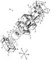
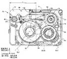
図1は、本発明の一実施形態であるカセット10を正面側すなわち上面から示す斜視図である。本実施形態の説明では、図1の上側をカセット10の前側とし、下側をカセット10の後側とし、右側をカセット10の左側とし、左側をカセット10の右側とし、左上側をカセット10の上側とし、右下側をカセット10の下側とする。図2は、カセット10を裏面側すなわち下面から示す斜視図である。図3は、カセット10の第1ケース部材12、第2ケース部材14、第3ケース部材16、および第4ケース部材18を分離させて、カセット10の内部構成を説明する斜視図である。カセット10は、全体として直方体状を成し、後述の図18に示す印刷装置102のカセット装着部104に着脱可能に装着される。カセット10は、第1ケース部材12および第2ケース部材14から構成される第1ケースすなわちテープケース20と、第3ケース部材16および第4ケース部材18から構成される第2ケースすなわちリボンケース21とを備えている。第1ケース部材12から第4ケース部材18の積重ね方向、すなわち図1に示す上下方向が、本発明における第1方向に対応する。また、図1に示す前後方向が、第1方向と直交する第2方向に対応し、図1に示す左右方向が、第1方向と第2方向とに直交する第3方向に対応する。
[Embodiment 1]
FIG. 1 is a perspective view showing acassette 10 that is an embodiment of the present invention from the front side, that is, from the top. In the description of this embodiment, the upper side of FIG. The upper side is the upper side, and the lower right side is the lower side of thecassette 10 . FIG. 2 is a perspective view showing thecassette 10 from the back side, that is, from the bottom side. FIG. 3 is a perspective view illustrating the internal configuration of thecassette 10 with thefirst case member 12, thesecond case member 14, thethird case member 16, and thefourth case member 18 of thecassette 10 separated. Thecassette 10 has a rectangular parallelepiped shape as a whole and is detachably attached to acassette attachment portion 104 of aprinting apparatus 102 shown in FIG. 18 which will be described later. Thecassette 10 comprises a first case ortape case 20 comprising afirst case member 12 and asecond case member 14, and a second case orribbon case 21 comprising athird case member 16 and afourth case member 18. and The stacking direction of thefirst case member 12 to thefourth case member 18, that is, the vertical direction shown in FIG. 1 corresponds to the first direction in the present invention. Further, the front-rear direction shown in FIG. 1 corresponds to the second direction orthogonal to the first direction, and the left-right direction shown in FIG. 1 corresponds to the third direction orthogonal to the first direction and the second direction.

リボンケース21は、テープケース20に対して上下方向の一方側に位置する。本実施形態では、リボンケース21は、テープケース20に対して上下方向の一方側である下側に位置する。テープケース20は、内部に形成された第1空間S1に、被印刷媒体である印刷テープ22が印刷テープスプール24に巻回された印刷テープロール26を備える。リボンケース21は、内部に形成された第2空間S2に、貼合せテープ60が貼合せスプール62に巻回された貼合せテープロール64と、インクリボン68が供給スプール70に巻回されたインクリボンロール72とを備える。本実施形態では、第1テープに対応する印刷テープ22が第1スプールに対応する印刷テープスプール24に巻回された印刷テープロール26が第1ロールに対応し、第2テープに対応する貼合せテープ60が第2スプールに対応する貼合せスプール62に巻回された貼合せテープロール64が第2ロールに対応し、インクリボン68が第3スプールに対応する供給スプール70に巻回されたインクリボンロール72が第3ロールに対応している。また、本実施形態では、カセット10は、第1空間S1を有するテープケース20が構成する第1層L1と第2空間S2を有するリボンケース21が構成する第2層L2とを含む少なくとも2層で構成されている。なお、上記各ロールたとえば印刷テープロール26の概念は、その印刷テープスプール24内に第1回転中心線C1方向に貫通する空間があったとしても、その空間を含んでいる。 Theribbon case 21 is positioned on one side of thetape case 20 in the vertical direction. In this embodiment, theribbon case 21 is located on the lower side, which is one side of thetape case 20 in the vertical direction. Thetape case 20 includes aprinting tape roll 26 in which aprinting tape 22, which is a medium to be printed, is wound around aprinting tape spool 24 in a first space S1 formed therein. Theribbon case 21 has, in a second space S2 formed therein, abonding tape roll 64 having abonding tape 60 wound around abonding spool 62 and anink ribbon 68 wound around asupply spool 70. and aribbon roll 72 . In the present embodiment, theprinting tape roll 26, in which theprinting tape 22 corresponding to the first tape is wound around theprinting tape spool 24 corresponding to the first spool, corresponds to the first roll, and the bonding corresponding to the second tape.Laminated tape roll 64, in which tape 60 is wound on laminatingspool 62, which corresponds to the second spool, corresponds to the second roll, andink ribbon 68, which is wound onsupply spool 70, which corresponds to the third spool. Aribbon roll 72 corresponds to the third roll. Further, in this embodiment, thecassette 10 has at least two layers including a first layer L1 formed by thetape case 20 having the first space S1 and a second layer L2 formed by theribbon case 21 having the second space S2. consists of Note that the concept of each roll, for example, theprinting tape roll 26 described above includes the space, even if there is a space penetrating theprinting tape spool 24 in the direction of the first rotation center line C1.

インクリボンロール72は、第1テープである帯状の印刷テープ22への印刷に使用される、帯状のインクリボン68が供給スプール70に巻回されている。貼合せテープロール64は、印刷された印刷テープ22に貼り合わされる帯状の貼合せテープ60が、貼合せテープ60の幅方向が第1方向である上下方向となるように貼合せスプール62に巻回されている。すなわち、貼合せテープロール64の径方向は前後方向及び左右方向を含む、上下方向に対して垂直な方向である。換言すると、径方向に直交する直交方向は上下方向である。第1ケース部材12、第2ケース部材14、第3ケース部材16および第4ケース部材18は、上下方向に相互に重ねられた状態で、相互の外周壁間にそれぞれ設けられた複数の係止爪27と固定爪28との係合と位置決め突起29による位置決めとによって相互に固定されている。なお、本実施形態において、各ケース部材12~18の上側の面を上面もしくは正面と称し、下側の面を下面もしくは裏面と称す。 Theink ribbon roll 72 has a belt-shapedink ribbon 68 wound around thesupply spool 70 for printing on the belt-shapedprinting tape 22 that is the first tape. Thebonding tape roll 64 is wound around thebonding spool 62 so that the band-shapedbonding tape 60 to be bonded to the printedprinting tape 22 is aligned with the width direction of thebonding tape 60 in the vertical direction, which is the first direction. being turned. That is, the radial direction of thebonding tape roll 64 is a direction perpendicular to the vertical direction including the front-rear direction and the left-right direction. In other words, the orthogonal direction perpendicular to the radial direction is the vertical direction. Thefirst case member 12, thesecond case member 14, thethird case member 16, and thefourth case member 18 are stacked one on top of the other in the vertical direction, and have a plurality of engagement members provided between their outer peripheral walls. They are fixed to each other by the engagement between theclaws 27 and the fixedclaws 28 and the positioning by thepositioning projections 29 . In this embodiment, the upper surfaces of thecase members 12 to 18 are referred to as upper surfaces or front surfaces, and the lower surfaces are referred to as lower surfaces or rear surfaces.

図2に示すように、カセット10の第4ケース部材18の下面には、上下方向に貫通する巻取スプール支持穴94が設けられている。また、第3ケース部材16および第4ケース部材18の前側の面、すなわち、リボンケース21の前側の面には、カセット10が印刷装置102のカセット装着部104に装着されたとき、カセット装着部104に設けられた後述の印刷ヘッド106が挿入されるヘッド開口として機能する凹溝99が形成されている。 As shown in FIG. 2, the lower surface of thefourth case member 18 of thecassette 10 is provided with a windingspool support hole 94 penetrating vertically. The front surfaces of thethird case member 16 and thefourth case member 18, that is, the front surface of theribbon case 21, are provided with a cassette mounting portion when thecassette 10 is mounted in thecassette mounting portion 104 of theprinting apparatus 102. A recessedgroove 99 functioning as a head opening into which aprint head 106, which will be described later, is provided in 104 is inserted is formed.

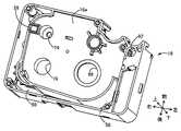
図4は、第1ケース部材12の上面側を示す正面図であり、図5は第1ケース部材12の下面側を示す斜視図である。図6は第2ケース部材14の上面側を示す正面図である。なお、図6では、印刷テープロール26から引き出された印刷テープ22の記載は省略されている。図7は第2ケース部材14の上面側を示す斜視図である。また、図8は印刷テープ22がテープケース20内からリボンケース21内へ架け渡されている状態を示す、図6のVIII-VIII視断面図である。図9は第2ケース部材14の下面側を示す斜視図であり、図10は第3ケース部材16の上(正)面側を示す斜視図であり、図11は第3ケース部材16の下(裏)面側を示す斜視部である。図12は第4ケース部材18の上(正)面側を示す斜視図であり、図13は第4ケース部材18の下(裏)面側を示す下(裏)面図である。 4 is a front view showing the upper surface side of thefirst case member 12, and FIG. 5 is a perspective view showing the lower surface side of thefirst case member 12. FIG. FIG. 6 is a front view showing the upper surface side of thesecond case member 14. FIG. 6, illustration of theprinting tape 22 pulled out from theprinting tape roll 26 is omitted. FIG. 7 is a perspective view showing the upper surface side of thesecond case member 14. FIG. 8 is a cross-sectional view taken along line VIII-VIII in FIG. 6, showing a state in which theprinting tape 22 is stretched from the inside of thetape case 20 to the inside of theribbon case 21. As shown in FIG. 9 is a perspective view showing the bottom side of thesecond case member 14, FIG. 10 is a perspective view showing the top (front) side of thethird case member 16, and FIG. It is a perspective part showing the (back) face side. 12 is a perspective view showing the top (front) side of thefourth case member 18, and FIG. 13 is a bottom (back) side view showing the bottom (back) side of thefourth case member 18. As shown in FIG.

第1ケース部材12と第2ケース部材14との間には、第1空間S1が形成されている。第1空間S1には、印刷テープロール26が上下方向に平行な第1回転中心線C1まわりに回転可能に収容されている。印刷テープロール26は、印刷テープ22が円筒状の軸芯材である印刷テープスプール24に巻回されて構成される。第1ケース部材12および第2ケース部材14は長方形状であって、第1回転中心線C1は、第1ケース部材12および第2ケース部材14における、第2方向である左右方向の中央略右寄り、且つ、第3方向である前後方向の略中央付近に位置している。印刷テープ22は、印刷ヘッド106によって印刷される被印刷媒体である。 A first space S<b>1 is formed between thefirst case member 12 and thesecond case member 14 . Aprinting tape roll 26 is accommodated in the first space S1 so as to be rotatable about a first rotation center line C1 parallel to the vertical direction. Theprinting tape roll 26 is configured by winding theprinting tape 22 around aprinting tape spool 24 that is a cylindrical core member. Thefirst case member 12 and thesecond case member 14 are rectangular, and the first rotation center line C1 is substantially to the right of the center of thefirst case member 12 and thesecond case member 14 in the left-right direction, which is the second direction. , and located near the approximate center in the front-rear direction, which is the third direction. Theprint tape 22 is the print medium that is printed on by theprint head 106 .

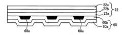
印刷テープ22は、第1テープに対応し、印刷テープロール26は第1ロールに対応し、印刷テープスプール24は第1スプールに対応している。印刷テープ22は、たとえば図15に示すように、剥離テープ22cが被印刷テープ22aの印刷面とは反対側の面に、粘着剤22bを介して積層されることにより構成されたものである。 Theprinting tape 22 corresponds to the first tape, theprinting tape roll 26 corresponds to the first roll, and theprinting tape spool 24 corresponds to the first spool. As shown in FIG. 15, for example, theprinting tape 22 is constructed by laminating a peelingtape 22c on the opposite side of the printing surface of theprinting tape 22a with an adhesive 22b interposed therebetween.

図3、図5、図6に示すように、第1ケース部材12の下面側には、円筒状の第1支持突起30と、第1円周壁34とが設けられる。第1支持突起30は、円筒状の印刷テープスプール24に挿入され印刷テープロール26を回転可能に支持する。第1ケース部材12は、短辺部44aと長辺部44bを有する外周壁44を備える。第1円周壁34は、印刷テープロール26の外径よりも大きい内径を有する。第1支持突起30と第1円周壁34は、第1回転中心線C1と同じ中心線を有する状態で第1ケース部材12の下面側から下向きに突設されている。図6及び図7に示すように、第2ケース部材14の上面側には、円筒状の第2支持突起32と、第2円周壁36とが設けられる。第2支持突起32は、円筒状の印刷テープスプール24に挿入され印刷テープロール26を回転可能に支持する。第2円周壁36は、印刷テープロール26の外径よりも大きい内径を有する。第2支持突起32と第2円周壁36は、第1回転中心線C1と同じ中心線を有する状態で第2ケース部材14の上面側から上向きに突設されている。印刷テープロール26は、印刷テープロール26の外径と略同じ外径を有する円形のスペーサフィルム38を印刷テープロール26の上下にそれぞれ介在させた状態で第1ケース部材12と第2ケース部材14との間に配設されている。 As shown in FIGS. 3, 5 and 6, a cylindricalfirst support projection 30 and a firstcircumferential wall 34 are provided on the lower surface side of thefirst case member 12 . Thefirst support protrusion 30 is inserted into the cylindricalprinting tape spool 24 and rotatably supports theprinting tape roll 26 . Thefirst case member 12 includes an outerperipheral wall 44 havingshort side portions 44a andlong side portions 44b. The firstcircumferential wall 34 has an inner diameter that is greater than the outer diameter of theprinting tape roll 26 . Thefirst support projection 30 and the firstcircumferential wall 34 protrude downward from the lower surface side of thefirst case member 12 while having the same center line as the first rotation center line C1. As shown in FIGS. 6 and 7 , a cylindricalsecond support projection 32 and a secondcircumferential wall 36 are provided on the upper surface side of thesecond case member 14 . Thesecond support protrusions 32 are inserted into the cylindricalprinting tape spool 24 and rotatably support theprinting tape roll 26 . The secondcircumferential wall 36 has an inner diameter that is greater than the outer diameter of theprinting tape roll 26 . Thesecond support projection 32 and the secondcircumferential wall 36 protrude upward from the upper surface side of thesecond case member 14 while having the same center line as the first rotation center line C1. Theprinting tape roll 26 is arranged between thefirst case member 12 and thesecond case member 14 withcircular spacer films 38 having substantially the same outer diameter as theprinting tape roll 26 interposed above and below theprinting tape roll 26, respectively. is placed between.

第1ケース部材12の下面側および第2ケース部材14の上面側には、図5および図6に示すように、印刷テープロール26から印刷テープ22を一定の位置から引き出すために第1円周壁34および第2円周壁36の一部を切り欠いて形成した印刷テープゲート40、42が形成されている。図6および図7に示すように、第2ケース部材14の上面側には、印刷テープロール26から引き出された印刷テープ22を一定の方向に案内するために、印刷テープゲート42の左端から左側へ伸びる案内壁50が形成されている。 5 and 6, on the bottom side of thefirst case member 12 and the top side of thesecond case member 14, there are first circumferential walls for drawing theprinting tape 22 from the printing tape roll 26 from a fixed position. 34 and a portion of the secondcircumferential wall 36 are cut away to form printedtape gates 40,42. As shown in FIGS. 6 and 7, on the upper surface side of thesecond case member 14, a left side from the left end of theprinting tape gate 42 is provided to guide theprinting tape 22 pulled out from theprinting tape roll 26 in a certain direction. Aguide wall 50 is formed extending to.

図6に示すように、印刷テープゲート42の左端から左側へ伸びる案内壁50は、外周壁46の短辺部46aに到達する前に長辺部46b側すなわち後方へ曲がり、第2円周壁36に沿って延設されて長辺部46bへ接続されている。 As shown in FIG. 6, theguide wall 50 extending leftward from the left end of theprinting tape gate 42 bends toward thelong side 46b, i.e. rearward, before reaching theshort side 46a of the outerperipheral wall 46, and the secondperipheral wall 36 and is connected to thelong side portion 46b.

図6に示すように、第2ケース部材14の底板14aには、案内壁50と外周壁46の長辺部46bとに沿って前後方向及び左右方向に延びる正面視略L字状の貫通穴52が形成されている。底板14aには、第2円周壁36のうち案内壁50および長辺部46bに対向する部分と貫通穴52との間において複数の案内リブ54が形成されている。複数の案内リブ54は、印刷テープロール26から巻き出され且つ印刷テープゲート40および42を通して送り出された印刷テープ22を貫通穴52内へ案内する。 As shown in FIG. 6, in thebottom plate 14a of thesecond case member 14, a substantially L-shaped through hole extending in the front-rear direction and the left-right direction along theguide wall 50 and thelong side portion 46b of the outerperipheral wall 46 is formed. 52 are formed. A plurality ofguide ribs 54 are formed on thebottom plate 14 a between the throughhole 52 and the portion of the secondcircumferential wall 36 facing theguide wall 50 and thelong side portion 46 b. A plurality ofguide ribs 54 guide theprinting tape 22 unwound from theprinting tape roll 26 and fed through theprinting tape gates 40 and 42 into the through holes 52 .

図7は、第1ケース部材12を取り除いたカセット10を示す。印刷テープロール26から巻き出された印刷テープ22が、貫通穴52を通して第3ケース部材16と第4ケース部材18との間の第2空間内S2へ導かれている状態を示している。印刷テープ22は、第1空間S1と第2空間内S2とを区画する板材として機能する底板14aに形成された貫通穴52を通して、テープケース20とリボンケース21とに架け渡される。 FIG. 7 shows thecassette 10 with thefirst case member 12 removed. Theprinting tape 22 unwound from theprinting tape roll 26 is shown to be guided into the second space S<b>2 between thethird case member 16 and thefourth case member 18 through the throughhole 52 . Theprinting tape 22 spans thetape case 20 and theribbon case 21 through a throughhole 52 formed in thebottom plate 14a that functions as a plate material that partitions the first space S1 and the second space S2.

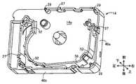
図8は印刷テープ22がテープケース20内からリボンケース21内へ架け渡されている状態を示す、図6のVIII-VIII視断面図である。図8に示すように、印刷テープ22は、貫通穴52を通して、テープケース20内からリボンケース21内へ斜めに架け渡される。より詳細には、後述する図14に示すように、印刷テープ22は、リボンケース21の凹溝99にまで架け渡されている。図9は、第2ケース部材14の下面側を示している。図9に示すように、第2ケース部材14の底板14aの裏面には、貫通穴52が開口しており、貫通穴52に沿って案内壁56が上下方向に立設されている。図10は、第3ケース部材16の上面側を示している。第3ケース部材16の天井板16eには、貫通穴58と、貼合せテープロール支持穴66と、インクリボン支持穴74と、巻取スプール支持穴78と、ローラ支持穴82とが、形成されている。貫通穴58は、印刷テープロール26から引き出された印刷テープ22を第2空間S2へ通すために、第2ケース部材14の貫通穴52に対応する位置に形成されている。つまり、貫通穴52の一部と貫通穴58の一部は上下方向において互いに重複している。 FIG. 8 is a cross-sectional view taken along line VIII-VIII in FIG. 6, showing a state in which theprinting tape 22 is stretched from the inside of thetape case 20 to the inside of theribbon case 21. As shown in FIG. As shown in FIG. 8, theprinting tape 22 is diagonally stretched from the inside of thetape case 20 to the inside of theribbon case 21 through the through holes 52 . More specifically, as shown in FIG. 14 to be described later, theprinting tape 22 is stretched over the recessedgroove 99 of theribbon case 21 . 9 shows the bottom side of thesecond case member 14. FIG. As shown in FIG. 9 , a throughhole 52 is opened in the rear surface of thebottom plate 14 a of thesecond case member 14 , and aguide wall 56 is provided vertically along the throughhole 52 . 10 shows the top side of thethird case member 16. FIG. Theceiling plate 16e of thethird case member 16 is formed with a throughhole 58, a bonding taperoll support hole 66, an inkribbon support hole 74, a take-upspool support hole 78, and aroller support hole 82. ing. A throughhole 58 is formed at a position corresponding to the throughhole 52 of thesecond case member 14 so that theprinting tape 22 pulled out from theprinting tape roll 26 is passed through the second space S2. That is, a portion of the throughhole 52 and a portion of the throughhole 58 overlap each other in the vertical direction.

第2ケース部材14の底板14aおよび第3ケース部材16の天井板16eは、テープケース20内の第1空間S1とリボンケース21内の第2空間S2とを区画する板体に対応している。 Thebottom plate 14a of thesecond case member 14 and theceiling plate 16e of thethird case member 16 correspond to plates that divide the first space S1 in thetape case 20 and the second space S2 in theribbon case 21. .

貼合せテープロール支持穴66は、貼合せテープ60が巻回された貼合せスプール62の一端を嵌め入れて貼合せテープロール64を第1回転中心線C1と平行な第2回転中心線C2まわりに回転可能に支持する。貼合せテープ60は、図15に示すように、印刷テープ22の印刷面を保護するためにたとえばこの印刷面と接触する一面に粘着剤60bが塗布された透明な媒体である透明フィルム60aから成る。貼合せテープ60は第2テープに対応し、貼合せテープロール64は第2ロールに対応し、貼合せスプール62は第2スプールに対応している。インクリボン支持穴74は、インクリボン68が巻回された供給スプール70の一端を嵌め入れてインクリボンロール72を第1回転中心線C1と平行な第3回転中心線C3まわりに回転可能に支持する。供給スプール70は第3スプールに対応している。巻取スプール支持穴78は、インクリボンロール72から巻き出されたインクリボン68を巻き取る巻取スプール76の一端を嵌め入れて巻取スプール76を第1回転中心線C1と平行な第4回転中心線C4まわりに回転可能に支持する。ローラ支持穴82は、印刷テープ22の印刷面と貼合せテープ60の接着面とを圧着するために印刷テープ22と貼合せテープ60とを印刷装置102のローラとの間で挟圧するローラ80の一端を嵌め入れてローラ80を第1回転中心線C1と平行な第5回転中心線C5まわりに回転可能に支持する。 One end of thelamination spool 62 around which thelamination tape 60 is wound is inserted into the lamination taperoll support hole 66 to rotate thelamination tape roll 64 around the second rotation center line C2 parallel to the first rotation center line C1. rotatably supported. As shown in FIG. 15, the laminatingtape 60 is composed of atransparent film 60a which is a transparent medium coated with an adhesive 60b on one side that contacts the printing surface of theprinting tape 22 in order to protect the printing surface. .Laminate tape 60 corresponds to the second tape,lamination tape roll 64 corresponds to the second roll, andlamination spool 62 corresponds to the second spool. One end of thesupply spool 70 around which theink ribbon 68 is wound is inserted into the inkribbon support hole 74 to support theink ribbon roll 72 rotatably around a third rotation center line C3 parallel to the first rotation center line C1. do.Supply spool 70 corresponds to the third spool. One end of a windingspool 76 for winding theink ribbon 68 unwound from theink ribbon roll 72 is fitted into the windingspool support hole 78, and the windingspool 76 is rotated in a fourth rotation parallel to the first rotation center line C1. It is rotatably supported around the center line C4. The roller support holes 82 are formed by therollers 80 that pinch theprinting tape 22 and thebonding tape 60 between the printingtape 22 and thebonding tape 60 and the rollers of theprinting device 102 in order to press the printing surface of theprinting tape 22 and the adhesive surface of thebonding tape 60 together. One end is fitted to support theroller 80 so as to be rotatable about a fifth rotation center line C5 parallel to the first rotation center line C1.

図11に示すように、第3ケース部材16の下面には、貼合せテープロール保持壁84と、インクリボンロール保持壁86と、円筒状突起88と、円弧状壁92とが、形成されている。貼合せテープロール保持壁84および円弧状壁92は、貼合せテープロール64の配置位置を規定するために貼合せテープロール支持穴66の周囲に貼合せテープロール支持穴66を中心とする円弧状に形成されている。インクリボンロール保持壁86は、巻取スプール76に巻き取られたインクリボン68のインクリボンロールの配置位置を規定するために巻取スプール支持穴78の周囲に巻取スプール支持穴78を中心とする円弧状に形成されている。円筒状突起88は、インクリボン支持穴74の周囲から下方に突設され且つ先端面に周方向に並ぶ凹凸が形成されている。第3ケース部材16は、外周壁として短辺部16aと長辺部16bと、凹溝99を囲むように配置されたU字状の凹部壁16cを備える。また、第3ケース部材16の下面には、張合せテープ60の張り付きを防止する張付防止ローラ91の上端部を回動可能に支持する支持突起93が設けられている。また、図12に示すように、第4ケース部材18の上面には、張付防止ローラ91の下端部を連結可能に支持する支持突起95が設けられている。 As shown in FIG. 11, the lower surface of thethird case member 16 is formed with a lamination taperoll holding wall 84, an ink ribbonroll holding wall 86, acylindrical protrusion 88, and anarcuate wall 92. there is Laminating taperoll holding wall 84 andarcuate wall 92 are formed in an arc around laminating taperoll supporting hole 66 to define the placement position of laminatingtape roll 64 . is formed in The ink ribbonroll retaining wall 86 is centered around the take-upspool support hole 78 to define the placement position of the ink ribbon roll of theink ribbon 68 wound on the take-upspool 76 . It is formed in an arc shape. Thecylindrical projection 88 projects downward from the periphery of the inkribbon support hole 74 and has unevenness arranged in the circumferential direction on the tip surface thereof. Thethird case member 16 has ashort side portion 16 a and along side portion 16 b as outer peripheral walls, and aU-shaped recess wall 16 c arranged so as to surround therecess groove 99 . Further, asupport protrusion 93 is provided on the lower surface of thethird case member 16 to rotatably support the upper end of a stickingprevention roller 91 that prevents sticking of the stickingtape 60 . Further, as shown in FIG. 12, the upper surface of thefourth case member 18 is provided with asupport protrusion 95 that supports the lower end of the stickingprevention roller 91 so as to be connectable.

図3に示されるように、インクリボン68が巻回された供給スプール70の他端には、クラッチばねを収容したクラッチばねホルダ90が嵌め付けられており、供給スプール70がクラッチばねホルダ90内のクラッチばねによってインクリボンロール72には適度の回転抵抗が付与されるようになっている。 As shown in FIG. 3, aclutch spring holder 90 containing a clutch spring is fitted to the other end of thesupply spool 70 around which theink ribbon 68 is wound. A suitable rotational resistance is imparted to theink ribbon roll 72 by the clutch spring of .

図12および図13は、第4ケース部材18の上面および下面を示している。第4ケース部材18には、巻取スプール76の他端を嵌め入れて巻取スプール76を回転可能に支持する巻取スプール支持穴94が上下方向に貫通して形成されている。巻取スプール76の他端側の端面に形成された連結穴96が、図2に示すように巻取スプール支持穴94を通して第4ケース部材18の下面に露出させられる。カセット10が印刷装置102に装着されたとき、後述の印刷装置102の巻取スプール駆動軸108が連結穴96内に挿入されて巻取スプール76に連結され、巻取スプール76が巻取スプール駆動軸108により回転駆動される。また、第4ケース部材18には、供給スプール70の他端を嵌め入れて供給スプール70を回転可能に支持する円筒状の支持突起97が形成されている。 12 and 13 show the upper and lower surfaces of thefourth case member 18. FIG. A take-upspool support hole 94 is formed through thefourth case member 18 in the vertical direction to receive the other end of the take-upspool 76 and rotatably support the take-upspool 76 . A connectinghole 96 formed in the end surface of the other end of the take-upspool 76 is exposed to the lower surface of thefourth case member 18 through the take-upspool support hole 94 as shown in FIG. When thecassette 10 is attached to theprinting device 102, the take-upspool driving shaft 108 of theprinting device 102, which will be described later, is inserted into the connectinghole 96 and connected to the take-upspool 76, and the take-upspool 76 is driven by the take-up spool. It is rotationally driven byshaft 108 . Further, thefourth case member 18 is formed with acylindrical support projection 97 that receives the other end of thesupply spool 70 to rotatably support thesupply spool 70 .

第4ケース部材18には、第3ケース部材16に形成されたローラ支持穴82に対応する位置に、ローラ80の軸端を露出させるローラ露出穴98が設けられている。ローラ80の第4ケース部材18側の端部に形成された連結部80aが、図2に示すようにローラ露出穴98を通して第4ケース部材18の下面に露出させられる。カセット10が印刷装置102に装着されたとき、後述の印刷装置102のローラ駆動軸110が連結部80aと連結され、ローラ80がローラ駆動軸110により回転駆動される。 Thefourth case member 18 is provided with aroller exposure hole 98 for exposing the shaft end of theroller 80 at a position corresponding to theroller support hole 82 formed in thethird case member 16 . A connectingportion 80a formed at the end portion of theroller 80 on the side of thefourth case member 18 is exposed to the lower surface of thefourth case member 18 through theroller exposing hole 98 as shown in FIG. When thecassette 10 is attached to theprinting device 102 , theroller driving shaft 110 of theprinting device 102 , which will be described later, is connected to the connectingportion 80 a , and theroller 80 is rotationally driven by theroller driving shaft 110 .

図14は、カセット10が印刷装置102のカセット装着部104に装着されたときの、第3ケース部材16の下面を示す図である。前述の通り、印刷テープ22は、印刷テープロール26から引き出され、貫通穴52および貫通穴58を介してテープケース20内の第1空間S1からリボンケース21内の第2空間S2に斜めに架け渡される。そのため、第3ケース部材16を示す図14において印刷テープ22は、第3ケース部材16の後方の貫通穴58から描画されている。図14に示すように、印刷テープ22および貼合せテープ60は、ローラ80と印刷装置102の押圧ローラ118とに挟圧され、ローラ80の駆動によって、各々印刷テープロール26および貼合せテープロール64から引き出される。インクリボン68は、巻取スプール76の駆動によってインクリボンロール72から引き出され、巻取スプール76に巻き取られる。印刷テープ22は二点鎖線で、貼合せテープ60は破線で、インクリボン68は一点鎖線で示されている。 FIG. 14 is a diagram showing the bottom surface of thethird case member 16 when thecassette 10 is attached to thecassette attachment portion 104 of theprinting apparatus 102. FIG. As described above, theprinting tape 22 is pulled out from theprinting tape roll 26 and diagonally stretched from the first space S1 in thetape case 20 to the second space S2 in theribbon case 21 through the throughholes 52 and 58. Passed. Therefore, in FIG. 14 showing thethird case member 16 , theprinting tape 22 is drawn from the throughhole 58 behind thethird case member 16 . As shown in FIG. 14, theprinting tape 22 and thebonding tape 60 are pressed between theroller 80 and thepressure roller 118 of theprinting device 102, and theroller 80 is driven to drive theprinting tape roll 26 and thebonding tape roll 64, respectively. drawn from. Theink ribbon 68 is pulled out from theink ribbon roll 72 by driving the windingspool 76 and wound on the windingspool 76 . Theprinting tape 22 is shown in dashed lines, thelamination tape 60 is shown in dashed lines, and theink ribbon 68 is shown in dashed lines.

図14に示すように、印刷ヘッド106とプラテンローラ116との間の印刷場所Pにおいて、印刷テープ22はインクリボン68を介して印刷ヘッド106に押しつけられる。この状態で、印刷ヘッド106の表面に配置された複数の発熱素子が選択的に駆動されて局所発熱することで、インクリボン68の一面に設けられたインク68aのうち一部が印刷テープ22に転写されて、印刷テープ22に文字、記号などが印刷される。印刷場所Pを通過した使用済のインクリボン68は巻取スプール76に巻き取られる。印刷場所Pを通過した印刷テープ22の印刷面は、ローラ80と印刷装置102の押圧ローラ118により透明な貼合せテープ60が狭圧されて接着される。これにより、印刷テープ22の印刷面は貼合せテープ60により保護される。 As shown in FIG. 14, theprinting tape 22 is pressed against theprint head 106 via theink ribbon 68 at a print location P between theprint head 106 and theplaten roller 116 . In this state, a plurality of heating elements arranged on the surface of theprint head 106 are selectively driven to locally generate heat, so that part of theink 68 a provided on one surface of theink ribbon 68 is transferred to theprinting tape 22 . Characters, symbols, etc. are printed on theprinting tape 22 by being transferred. The usedink ribbon 68 that has passed through the printing place P is taken up by the take-upspool 76 . The printing surface of theprinting tape 22 that has passed through the printing place P is pressed against thetransparent bonding tape 60 by theroller 80 and thepressing roller 118 of theprinting device 102 and adhered. Thereby, the printing surface of theprinting tape 22 is protected by thebonding tape 60 .

図15は、カセット10から送り出された印刷テープ22および貼合せテープ60の積層体を模式的に示している。印刷テープ22の被印刷テープ22a側すなわち印刷面側に、一面に粘着剤60bが塗布された透明フィルム60aから構成された貼合せテープ60が、貼り着けられている。これにより、印刷テープ22の印刷面に転写されたインク68aが保護される。なお、図15に描かれた積層体の各部材22a~22c,60a,60b,68aの大きさや寸法比等は必ずしも正確ではない。 FIG. 15 schematically shows a laminate of theprinting tape 22 and thebonding tape 60 fed from thecassette 10. As shown in FIG. Alamination tape 60 composed of atransparent film 60a coated with an adhesive 60b on one side is adhered to theprint tape 22a side of theprinting tape 22, that is, the printing surface side. As a result, theink 68a transferred to the printing surface of theprinting tape 22 is protected. Note that the sizes and dimensional ratios of themembers 22a to 22c, 60a, 60b, and 68a of the laminate shown in FIG. 15 are not necessarily accurate.

図16は、第3ケース部材16の下面を示す図である。図16には、テープケース20に対して下方に重ねて配置されているリボンケース21内、すなわち第3ケース部材16と第4ケース部材18との間の第2空間S2内に配置された貼合せテープロール64、インクリボンロール72、巻取スプール76、およびローラ80が示されている。また、図16には、第2空間S2内で上下方向(第1方向)に直交する、前後方向および左右方向に広がる投影面上に投影された、テープケース20内の印刷テープロール26、印刷テープスプール24、およびスペーサフィルム38が、1点鎖線で示されている。なお、スペーサフィルム38は印刷テープロール26と略同じ直径を有するので、図16では印刷テープロール26を表す一点鎖線で示される。 16 is a diagram showing the bottom surface of thethird case member 16. FIG. In FIG. 16, theribbon case 21 is placed under thetape case 20, i.e., in the second space S2 between thethird case member 16 and thefourth case member 18. In FIG. Laminatingtape roll 64,ink ribbon roll 72, take-upspool 76, androller 80 are shown. FIG. 16 also shows theprinting tape roll 26 in thetape case 20 and theprinting tape roll 26 in thetape case 20 projected onto a projection plane extending in the front-rear direction and the left-right direction perpendicular to the up-down direction (first direction) in the second space S2.Tape spool 24 andspacer film 38 are shown in dashed lines. Since thespacer film 38 has approximately the same diameter as theprinting tape roll 26, it is indicated by a dashed line representing theprinting tape roll 26 in FIG.

図16では、印刷テープロール26、貼合せテープロール64、およびインクリボンロール72は、それぞれ未使用の初期状態の大きさを示している。図16において、印刷テープロール26の径は、貼合せテープロール64の径よりも大きく、貼合せテープロール64の径はインクリボンロール72の径よりも大きく、インクリボンロール72の径は巻取スプール76の径よりも大きい。前後方向および左右方向における印刷テープロール26の大きさ(径寸法d)、すなわち印刷テープロール26の直径は、前後方向および左右方向の各方向におけるカセット10の大きさの半分の大きさよりも大きい。換言すると、印刷テープロール26の左右方向の寸法は、カセット10の左右方向の寸法の半分の寸法Lよりも大きく、印刷テープロール26の前後方向の寸法は、カセット10の前後方向の寸法の半分の寸法よりも大きい。 In FIG. 16, theprinting tape roll 26, thelamination tape roll 64, and theink ribbon roll 72 each show the size of an unused initial state. In FIG. 16, the diameter of theprinting tape roll 26 is larger than the diameter of thelamination tape roll 64, the diameter of thelamination tape roll 64 is larger than the diameter of theink ribbon roll 72, and the diameter of theink ribbon roll 72 is larger than the diameter of thespool 76. The size (diameter dimension d) of theprinting tape roll 26 in the front-back direction and the left-right direction, that is, the diameter of theprinting tape roll 26 is larger than half the size of thecassette 10 in each of the front-back direction and the left-right direction. In other words, the lateral dimension of theprinting tape roll 26 is greater than the dimension L, which is half the lateral dimension of thecassette 10 , and the longitudinal dimension of theprinting tape roll 26 is half the longitudinal dimension of thecassette 10 . larger than the dimensions of

図16に示すように、貼合せテープロール64の一部、貼合せスプール62、およびそれらの回転中心である第2回転中心線C2と、インクリボンロール72の一部、供給スプール70の一部、及びそれらの回転中心である第3回転中心線C3と、巻取スプール76の一部およびその回転中心である第4回転中心線C4と、後述のカセット10の中心位置Mとは、印刷テープロール26とそれぞれ上下方向(第1方向)において重なっていて、印刷テープロール26の投影面の中に位置している。また、貼合せテープロール64および貼合せスプール62の一部と、巻取スプール76の一部と、後述のカセット10の中心位置Mとは、それぞれ上下方向(第1方向)において印刷テープスプール24と重なっていて、印刷テープスプール24の投影面の中に位置している。印刷テープロール26の回転中心である第1回転中心線C1は、貼合せテープロール64と上下方向において重なっており、第2回転中心線C2と第3回転中心線C3或いは第4回転中心線C4との間に位置している。また、印刷テープロール26(第1ロール)の回転中心である第1回転中心線C1は、貼合せテープロール(第2ロール)64の外周円およびインクリボンロール(第3ロール)72の外周円とそれら外周円に接する2本の接線とによって定義される閉曲線である凸包絡(線)Hの中に位置している。このような位置関係から明らかなように、印刷テープロール26の少なくとも一部は、貼合せテープロール64の少なくとも一部と、第1回転中心線C1と平行な第1方向において重なっている。なお、第1回転中心線C1は、印刷テープロール26の回転中心であるとともに、印刷テープスプール24の回転中心でもある。また、第2回転中心線C2は、貼合せテープロール64の回転中心であるとともに、貼合せテープスプール62の回転中心でもある。なお、第3回転中心線C3は、インクリボンロール72の回転中心であるとともに、供給スプール70の回転中心でもある。また、第4回転中心線C4は、巻取スプール24の回転中心である As shown in FIG. 16, a portion of thelamination tape roll 64, alamination spool 62, a second rotation center line C2 as their rotation center, a portion of theink ribbon roll 72, and a portion of thesupply spool 70 , and a third rotation center line C3 that is the center of rotation thereof, a fourth rotation center line C4 that is a portion of the take-upspool 76 and its center of rotation, and a center position M of thecassette 10 to be described later. It overlaps theroll 26 in the vertical direction (first direction) and is located in the projection plane of theprinting tape roll 26 . A part of thebonding tape roll 64 and thebonding spool 62, a part of the take-upspool 76, and a center position M of thecassette 10, which will be described later, are arranged in the vertical direction (first direction) of theprinting tape spool 24. and lies in the plane of projection of theprinting tape spool 24 . The first rotation center line C1, which is the rotation center of theprinting tape roll 26, overlaps thebonding tape roll 64 in the vertical direction, and the second rotation center line C2 and the third rotation center line C3 or the fourth rotation center line C4. is located between Also, the first rotation center line C1, which is the rotation center of the printing tape roll 26 (first roll), is the outer circumference of the bonding tape roll (second roll) 64 and the outer circumference of the ink ribbon roll (third roll) 72. and two tangent lines tangent to these outer circles. As is clear from this positional relationship, at least a portion of theprinting tape roll 26 overlaps at least a portion of thelamination tape roll 64 in the first direction parallel to the first rotation centerline C1. The first rotation center line C<b>1 is the rotation center of theprinting tape roll 26 and also the rotation center of theprinting tape spool 24 . Further, the second rotation center line C2 is the rotation center of thebonding tape roll 64 and the rotation center of thebonding tape spool 62 as well. The third rotation center line C3 is the center of rotation of theink ribbon roll 72 and the center of rotation of thesupply spool 70 as well. Further, the fourth rotation center line C4 is the rotation center of the take-upspool 24.

図16に示すように、印刷テープ22が巻回された印刷テープスプール24の少なくとも一部と、貼合せテープ60が巻回された貼合せスプール62の少なくとも一部と、インクリボン68が巻回された供給スプール70の少なくとも一部とは、第1直線SL1上に沿って配置され、第1直線SL1上に並んでいる。また、リボンケース21には、前述のように、カセット10の装着状態において印刷ヘッド106を収容する凹溝99すなわちヘッド開口が形成されており、インクリボン68が巻き取られる巻取スプール76と凹溝99すなわちヘッド開口とは、第1直線SL1を挟む位置に、すなわち第1直線SL1に対して反対側の位置に配置されている。そして、巻取スプール76の少なくとも一部と印刷テープロール(第1ロール)26の回転中心である第1回転中心線C1とを結ぶ第2直線SL2は、第1直線SL1と直交する位置に形成される。すなわち、第1直線SL1と直交する第2直線SL2上に、巻取スプール76の少なくとも一部と印刷テープロール(第1ロール)26の回転中心である第1回転中心線C1とが、位置させられている。 As shown in FIG. 16, at least a portion of theprinting tape spool 24 around which theprinting tape 22 is wound, at least a portion of thebonding spool 62 around which thebonding tape 60 is wound, and anink ribbon 68 are wound. At least a part of the suppliedspool 70 is arranged along the first straight line SL1 and aligned on the first straight line SL1. Further, as described above, theribbon case 21 is formed with the recessedgroove 99, i.e., the head opening, for accommodating theprint head 106 when thecassette 10 is mounted. Thegroove 99, ie, the head opening, is arranged at a position sandwiching the first straight line SL1, that is, at a position opposite to the first straight line SL1. A second straight line SL2 connecting at least a portion of the take-upspool 76 and the first rotation center line C1, which is the center of rotation of the printing tape roll (first roll) 26, is formed at a position orthogonal to the first straight line SL1. be done. That is, at least a portion of the take-upspool 76 and the first rotation center line C1, which is the rotation center of the printing tape roll (first roll) 26, are positioned on a second straight line SL2 orthogonal to the first straight line SL1. It is

図16において、印刷テープロール26の第1回転中心線C1は、貼合せテープロール64の第2回転中心線C2とインクリボンロール72の第3回転中心線C3との間を結ぶ直線の中間点近傍に位置する。第1回転中心線C1は、前後方向及び左右方向において貼合せテープロール64に重なる。すなわち、印刷テープロール26の回転中心は、貼合せテープロール64と上下方向に重なる。巻取スプール76の第4回転中心線C4は第1直線SL1の凹溝99とは反対側に位置している。第4回転中心線C4と第1中心線C1との間の距離は、第3回転中心線C3と第1中心線C1との間の距離よりも短く、第2回転中心線C2と第1中心線C1との間の距離よりも短い。 In FIG. 16, the first rotational center line C1 of theprinting tape roll 26 is the middle point of a straight line connecting the second rotational center line C2 of thelamination tape roll 64 and the third rotational center line C3 of theink ribbon roll 72. located nearby. The first rotation center line C1 overlaps thebonding tape roll 64 in the front-rear direction and the left-right direction. That is, the center of rotation of theprinting tape roll 26 vertically overlaps thebonding tape roll 64 . The fourth rotation center line C4 of the take-upspool 76 is located on the opposite side of the first straight line SL1 from theconcave groove 99. As shown in FIG. The distance between the fourth rotation centerline C4 and the first centerline C1 is shorter than the distance between the third rotation centerline C3 and the first centerline C1, and the distance between the second rotation centerline C2 and the first centerline C1 shorter than the distance between lines C1.

また、図16に示すように、前後方向および左右方向において、カセット10の前後方向の中心であり、且つ、左右方向の中心である中心位置Mと、印刷テープロール26の回転中心である第1回転中心線C1との間の距離は、中心位置Mと貼合せテープロール64の回転中心である第2回転中心線C2との間の距離よりも小さい。また、前後方向および左右方向において、中心位置Mと、印刷テープロール26の第1回転中心線C1との間の距離は、中心位置Mとインクリボンロール72の第3回転中心線C3との間の距離よりも短く、中心位置Mと巻取スプール76の第4回転中心線C4との間の距離よりも短い。つまり、前後方向及び左右方向において、第1回転中心線C1は、第2回転中心線C2乃至第4回転中心線C4のいずれよりもカセット10の中心に近い位置に配置されている。 Further, as shown in FIG. 16, in the front-back direction and the left-right direction, a center position M that is the center of thecassette 10 in the front-rear direction and the center in the left-right direction, and a first position M that is the center of rotation of theprinting tape roll 26 . The distance between the rotation center line C1 is smaller than the distance between the center position M and the second rotation center line C2, which is the rotation center of thelamination tape roll 64. FIG. In addition, in the front-rear direction and the left-right direction, the distance between the center position M and the first rotation center line C1 of theprinting tape roll 26 is the distance between the center position M and the third rotation center line C3 of theink ribbon roll 72. and shorter than the distance between the center position M and the fourth rotation center line C4 of the take-upspool 76. That is, the first rotation center line C1 is located closer to the center of thecassette 10 than any of the second to fourth rotation center lines C2 to C4 in the front-rear direction and the left-right direction.

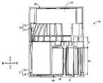
図17は、図6のXVII-XVII視断面図である。上下方向において、印刷テープロール26の上下方向の一方側(下側)端部と、貼合せテープロール64の上下方向の他方側(上側)端部との間の距離Dは、貼合せテープロール64の一方向の長さ(貼合せテープ60の幅寸法W1)よりも小さい。印刷テープ22と貼合せテープ60とは同じ幅寸法であるので、距離Dは、印刷テープロール26の幅寸法よりも小さい。 17 is a cross-sectional view taken along line XVII-XVII of FIG. 6. FIG. In the vertical direction, the distance D between the one (lower) end of theprinting tape roll 26 in the vertical direction and the other (upper) end of thebonding tape roll 64 in the vertical direction is 64 in one direction (the width dimension W1 of the bonding tape 60). Since theprinting tape 22 and thelamination tape 60 have the same width dimension, the distance D is smaller than the width dimension of theprinting tape roll 26 .

そして、上下方向と直交する前後方向、及び、上下方向と前後方向とに直交する左右方向において、カセット10の前後方向の中心及び左右方向の中心である中心位置Mから印刷テープロール26の回転中心である第1回転中心線C1までの距離は、中心位置Mから貼合せテープロール64の回転中心である第2回転中心線C2までの距離よりも小さい。印刷テープロール26の径は貼合せテープロール64の径よりも大きい。この印刷テープロール26、巻取スプール76、インクリボン68が巻回された供給スプール70の外周円を接線で結ぶことにより形成される凸包絡(線)Hの大きさ(面積)は、上下方向と直交する前後方向および左右方向を含む面内において、テープケース20およびリボンケース21の面積の半分よりも大きく設定されている。 In the front-rear direction perpendicular to the vertical direction and in the left-right direction perpendicular to the up-down direction and the front-rear direction, the rotation center of theprinting tape roll 26 is shifted from the center position M, which is the center in the front-rear direction and the center in the left-right direction of thecassette 10. is smaller than the distance from the center position M to the second rotation center line C2, which is the rotation center of thebonding tape roll 64. The diameter of theprinting tape roll 26 is greater than the diameter of thelaminating tape roll 64 . The size (area) of a convex envelope (line) H formed by connecting the outer peripheral circles of theprinting tape roll 26, the take-upspool 76, and thesupply spool 70 around which theink ribbon 68 is wound with tangential lines is is set to be larger than half the area of thetape case 20 and theribbon case 21 in a plane including the front-rear direction and the left-right direction perpendicular to the .

図18は、印刷システム122に含まれる印刷装置102の一部に設けられたカセット装着部104を示している。カセット装着部104には、嵌め入れられたカセット10を位置決めする矩形の位置決め穴112と、位置決め穴112の底面に立設された巻取スプール駆動軸108およびローラ駆動軸110とが設けられている。位置決め穴112は、カセット10の下ケースであるリボンケース21の一部を収容する収容部として機能している。これら巻取スプール駆動軸108およびローラ駆動軸110は、図示しないステップモータによりギヤ機構を介して同じ方向に回転駆動される。また、カセット装着部104の位置決め穴112の底面には、熱式の印刷ヘッド(サーマルプリントヘッド)106が固着されたヘッド保持板114が立設されており、プラテンローラ116および押圧ローラ118が回転可能に先端部に設けられたプラテン保持部材120がその基端部まわりに回動可能に設けられている。ヘッド保持板114は、たとえばアルミニウム製の金属板であって、印刷ヘッドのヒートシンクを兼ねている。 FIG. 18 shows thecassette mounting section 104 provided in a part of theprinting device 102 included in theprinting system 122. As shown in FIG. Thecassette mounting portion 104 is provided with arectangular positioning hole 112 for positioning the fittedcassette 10 , and a take-upspool drive shaft 108 and aroller drive shaft 110 erected on the bottom surface of thepositioning hole 112 . . Thepositioning hole 112 functions as an accommodation portion that accommodates a portion of theribbon case 21 that is the lower case of thecassette 10 . The take-upspool drive shaft 108 androller drive shaft 110 are rotated in the same direction by a step motor (not shown) via a gear mechanism. Ahead holding plate 114 to which athermal print head 106 is fixed is erected on the bottom surface of thepositioning hole 112 of thecassette mounting portion 104. Aplaten roller 116 and apressure roller 118 rotate. Aplaten holding member 120 is provided at its distal end and is rotatable about its proximal end. Thehead holding plate 114 is a metal plate made of aluminum, for example, and also serves as a heat sink for the print head.

カセット10が、印刷装置102のカセット装着部104に装着されると、カセット装着部104に立設された巻取スプール駆動軸108およびローラ駆動軸110が巻取スプール76およびローラ80に連結される。次いで、カセット10がカセット装着部104に装着された状態で印刷装置102の図示しないカバーが閉じられると、プラテン保持部材120がその基端部まわりに回動させられて、プラテンローラ116および押圧ローラ118が印刷ヘッド106およびカセット10のローラ80へ押圧されるようになっている。印刷装置102とカセット10とが、印刷システム122を構成している。 When thecassette 10 is attached to thecassette attachment portion 104 of theprinting apparatus 102 , the take-upspool drive shaft 108 and theroller drive shaft 110 erected on thecassette attachment portion 104 are connected to the take-upspool 76 and theroller 80 . . Next, when the cover (not shown) of theprinting apparatus 102 is closed with thecassette 10 attached to thecassette attachment portion 104, theplaten holding member 120 is rotated around its base end portion, and theplaten roller 116 and the pressure roller are rotated. 118 are adapted to be pressed against theprint head 106 and therollers 80 of thecassette 10 . Theprinting device 102 and thecassette 10 constitute aprinting system 122 .

本実施形態のカセット10によれば、第1層L1に配置され、印刷される印刷テープ(第1テープ)22が巻回されて構成される印刷テープロール(第1ロール)26と、第2層L2に配置され、印刷テープ(第1テープ)22に貼り合わされる貼合せテープ(第2テープ)60が巻回されて構成される貼合せテープロール(第2ロール)64とを備えた2層構造のカセット10であって、印刷テープロール26の少なくとも一部は、貼合せテープロール64の少なくとも一部と、印刷テープロール26の回転中心である第1回転中心線C1と平行な第1方向に重なっている。これにより、カセット10は、テープロール26の少なくとも一部が、貼合せテープロール64の少なくとも一部と第1方向に重なっていない場合よりも、小型化が可能となる。 According to thecassette 10 of the present embodiment, the printing tape roll (first roll) 26 arranged on the first layer L1 and configured by winding a printing tape (first tape) 22 to be printed (first roll) 26; a laminating tape roll (second roll) 64 arranged on the layer L2 and configured by winding a laminating tape (second tape) 60 laminated to the printing tape (first tape) 22; In thelayered cassette 10 , at least a portion of theprinting tape roll 26 is aligned with at least a portion of thelamination tape roll 64 and a first rotation centerline C 1 parallel to the rotation center of theprinting tape roll 26 . direction overlaps. This allows thecassette 10 to be made smaller than when at least a portion of thetape roll 26 does not overlap at least a portion of thelamination tape roll 64 in the first direction.

本実施形態のカセット10によれば、印刷テープロール(第1ロール)26と、第2層L2に配置され、印刷テープロール26の印刷テープ(第1テープ)22の印刷に使用されるインクリボン68が巻回されたインクリボンロール(第3ロール)72の少なくとも一部とが、第1方向に重なっている。これにより、カセット10は、印刷テープロール26とインクリボンロール72の少なくとも一部とが重なっていない場合よりも、小型化が可能となる。 According to thecassette 10 of the present embodiment, the printing tape roll (first roll) 26 and the ink ribbon disposed on the second layer L2 and used for printing on the printing tape (first tape) 22 of theprinting tape roll 26 At least part of the ink ribbon roll (third roll) 72 around which 68 is wound overlaps in the first direction. This allows thecassette 10 to be made smaller than when theprinting tape roll 26 and at least a portion of theink ribbon roll 72 do not overlap.

本実施形態のカセット10によれば、印刷テープロール(第1ロール)26と、第2層L2に配置され、印刷テープ(第1テープ)22の印刷に使用されるインクリボン68が巻き取られる巻取スプール76の少なくとも一部とが、第1方向に重なっている。これにより、カセット10は、印刷テープロール26と巻取スプール76の少なくとも一部とが第1方向に重なっていない場合よりも、小型化が可能となる。 According to thecassette 10 of the present embodiment, the printing tape roll (first roll) 26 and theink ribbon 68 arranged on the second layer L2 and used for printing the printing tape (first tape) 22 are wound up. At least part of the take-upspool 76 overlaps in the first direction. This allows thecassette 10 to be made smaller than when theprinting tape roll 26 and at least a portion of the take-upspool 76 do not overlap in the first direction.

本実施形態のカセット10によれば、印刷テープロール(第1ロール)26の回転中心である第1回転中心線C1は、貼合せテープロール(第2ロール)64の回転中心である第2回転中心線C2と供給スプール70の回転中心である第3回転中心線C3あるいは巻取スプール76の回転中心である第4回転中心線C4との間にある。これにより、カセット10は、第1回転中心線C1が、第2回転中心線C2と第3回転中心線C3あるいは第4回転中心線C4との間にない場合よりも、小型化が可能となる。 According to thecassette 10 of the present embodiment, the first rotation center line C1, which is the rotation center of the printing tape roll (first roll) 26, is the second rotation center line, which is the rotation center of the bonding tape roll (second roll) 64. It is between the center line C2 and the third rotation center line C3 that is the rotation center of thesupply spool 70 or the fourth rotation center line C4 that is the rotation center of the take-upspool 76. As a result, thecassette 10 can be made smaller than when the first rotation center line C1 is not between the second rotation center line C2 and the third rotation center line C3 or the fourth rotation center line C4. .

本実施形態のカセット10によれば、印刷テープロール(第1ロール)26の回転中心である第1回転中心線C1は、貼合せテープロール(第2ロール)64の外周円およびリンクリボンロール(第3ロール)72の外周円とそれら外周円に接する2本の接線とによって定義される閉曲線である凸包絡(線)Hの中にある。これにより、カセット10は、印刷テープロール26の第1回転中心線C1が貼合せテープロール64の外周円およびインクリボンロール72の外周円とそれらの外周円に接する2本の接線とによって定義される凸包絡(線)Hの中にない場合よりも、小型化が可能となる。 According to thecassette 10 of the present embodiment, the first rotation center line C1, which is the rotation center of the printing tape roll (first roll) 26, is aligned with the outer circumference of the bonding tape roll (second roll) 64 and the link ribbon roll ( It lies within a convex envelope (line) H, which is a closed curve defined by the outer circumference of thethird roll 72 and two tangent lines tangent to the outer circumference. Thus, in thecassette 10, the first rotation centerline C1 of theprinting tape roll 26 is defined by the outer circumference circles of thelaminating tape roll 64 and theink ribbon roll 72 and two tangent lines that contact these circumference circles. The size can be reduced more than in the case where it is not in the convex envelope (line) H.

本実施形態のカセット10によれば、印刷テープ(第1テープ)22が巻回された印刷テープスプール(第1スプール)24の少なくとも一部と、貼合せテープ(第2テープ)60が巻回された貼合せスプール(第2スプール)62の少なくとも一部と、インクリボン68が巻回された供給スプール(第3スプール)70の少なくとも一部とは、第1直線SL1上に並ぶ。これにより、カセット10は、印刷テープ22が巻回された印刷テープスプール24の少なくとも一部と、貼合せテープ60が巻回された貼合せスプール62の少なくとも一部と、インクリボン68が巻回された供給スプール70の少なくとも一部とが、第1直線SL1上に並んでいない場合よりも、小型化が可能となる。 According to thecassette 10 of the present embodiment, at least a portion of the printing tape spool (first spool) 24 around which the printing tape (first tape) 22 is wound and the bonding tape (second tape) 60 are wound. At least part of the bonded spool (second spool) 62 and at least part of the supply spool (third spool) 70 around which theink ribbon 68 is wound are aligned on the first straight line SL1. As a result, thecassette 10 includes at least a portion of theprinting tape spool 24 around which theprinting tape 22 is wound, at least a portion of thebonding spool 62 around which thebonding tape 60 is wound, and theink ribbon 68. At least a portion of thesupply spool 70 that is aligned with the first straight line SL1 is not arranged on the first straight line SL1.

本実施形態のカセット10によれば、インクリボン68が巻き取られる巻取スプール76と、カセット10の装着時に印刷ヘッド106が収容される凹溝(ヘッド開口)11が更に設けられ、巻取スプール76と凹溝99とは、第1直線SL1を挟む位置に配置されている。これにより、カセット10は、巻取スプール76と凹溝99とが第1直線SL1を挟む位置に配置されていない場合よりも、小型化が可能となる。 According to thecassette 10 of this embodiment, the windingspool 76 on which theink ribbon 68 is wound, and the concave groove (head opening) 11 in which theprint head 106 is accommodated when thecassette 10 is mounted are further provided. 76 and recessedgroove 99 are arranged at positions sandwiching first straight line SL1. As a result, thecassette 10 can be made smaller than when the take-upspool 76 and the recessedgroove 99 are not positioned to sandwich the first straight line SL1.

本実施形態のカセット10によれば、インクリボン68が巻き取られる巻取スプール76が設けられ、巻取スプール76の少なくとも一部と印刷テープロール(第1ロール)26の回転中心である第1回転中心線C1を結ぶ第2直線SL2は、第1直線SL1と直交する。これにより、カセット10は、巻取スプール76の少なくとも一部と印刷テープロール(第1ロール)26の第1回転中心線C1とを結ぶ第2直線SL2が第1直線SL1と直交しない場合よりも、小型化が可能となる。 According to thecassette 10 of this embodiment, the windingspool 76 on which theink ribbon 68 is wound is provided. A second straight line SL2 connecting the rotation center lines C1 is orthogonal to the first straight line SL1. As a result, thecassette 10 can be arranged more smoothly than when the second straight line SL2 connecting at least a portion of the take-upspool 76 and the first rotation center line C1 of the printing tape roll (first roll) 26 is not perpendicular to the first straight line SL1. , can be made smaller.

本実施形態のカセット10によれば、印刷テープロール(第1ロール)26の直径は、貼合せテープロール(第2ロール)64の直径及びリンクリボンロール(第3ロール)72の直径より大きい。これにより、カセット10は、印刷テープロール26の直径が貼合せテープロール64の直径及びインクリボンロール72の直径より大きくない場合よりも、小型化が可能となる。 According to thecassette 10 of this embodiment, the diameter of the printing tape roll (first roll) 26 is larger than the diameter of the laminating tape roll (second roll) 64 and the diameter of the link ribbon roll (third roll) 72 . This allows thecassette 10 to be smaller than if the diameter of theprinting tape roll 26 was no greater than the diameter of thelaminating tape roll 64 and the diameter of theink ribbon roll 72 .

本実施形態のカセット10によれば、印刷テープロール(第1ロール)26の第1回転中心線C1の方向と、貼合せテープロール(第2ロール)64の第2回転中心線C2方向と、リンクリボンロール(第3ロール)72の第3中心線C3の方向は、第1方向と平行である。これにより、カセット10は、印刷テープロール26の第1回転中心線C1の方向と貼合せテープロール64の第2回転中心線C2の方向とインクリボンロール72の第3回転中心線C3方向とが、第1方向と平行でない場合よりも、小型化が可能となる。 According to thecassette 10 of the present embodiment, the direction of the first rotation center line C1 of the printing tape roll (first roll) 26, the direction of the second rotation center line C2 of the bonding tape roll (second roll) 64, The direction of the third center line C3 of the link ribbon roll (third roll) 72 is parallel to the first direction. Thus, in thecassette 10, the direction of the first rotation center line C1 of theprinting tape roll 26, the direction of the second rotation center line C2 of thebonding tape roll 64, and the direction of the third rotation center line C3 of theink ribbon roll 72 are aligned. , the size can be reduced more than in the case of not being parallel to the first direction.

本実施形態のカセット10によれば、印刷テープロール(第1ロール)26の少なくとも一部と貼合せスプール(第2スプール)62の少なくとも一部とが第1方向に重なる。これにより、カセット10は、印刷テープロール26の少なくとも一部と貼合せスプール62の少なくとも一部とが第1方向に重ならない場合よりも、小型化が可能となる。 According to thecassette 10 of the present embodiment, at least part of the printing tape roll (first roll) 26 and at least part of the bonding spool (second spool) 62 overlap in the first direction. This allows thecassette 10 to be made smaller than when at least a portion of theprinting tape roll 26 and at least a portion of thelaminating spool 62 do not overlap in the first direction.

本実施形態のカセット10によれば、印刷テープスプール(第1スプール)24の少なくとも一部と貼合せテープロール(第2ロール)64の少なくとも一部とが第1方向に重なる。これにより、カセット10は、印刷テープスプール24の少なくとも一部と貼合せテープロール64の少なくとも一部とが第1方向に重ならない場合よりも、小型化が可能となる。 According to thecassette 10 of the present embodiment, at least part of the printing tape spool (first spool) 24 and at least part of the bonding tape roll (second roll) 64 overlap in the first direction. This allows thecassette 10 to be made smaller than when at least a portion of theprinting tape spool 24 and at least a portion of thelamination tape roll 64 do not overlap in the first direction.

本実施形態のカセット10によれば、印刷テープスプール(第1スプール)24の少なくとも一部と貼合せスプール(第2スプール)62の少なくとも一部とが第1方向に重なる。これにより、カセット10は、印刷テープスプール24の少なくとも一部と貼合せスプール62の少なくとも一部とが第1方向に重ならない場合よりも、小型化が可能となる。 According to thecassette 10 of the present embodiment, at least part of the printing tape spool (first spool) 24 and at least part of the bonding spool (second spool) 62 overlap in the first direction. This allows thecassette 10 to be made smaller than when at least a portion of theprinting tape spool 24 and at least a portion of thelaminating spool 62 do not overlap in the first direction.

本実施形態のカセット10によれば、印刷テープロール(第1ロール)26と貼合せテープロール(第2ロール)64の第2回転中心線C2とが第1方向に重なる。これにより、カセット10は、第1ロールと第2ロールの回転中心とが第1方向に重ならない場合よりも、小型化が可能となる。 According to thecassette 10 of the present embodiment, the printing tape roll (first roll) 26 and the bonding tape roll (second roll) 64 overlap the second rotation center line C2 in the first direction. Thereby, thecassette 10 can be made smaller than when the rotation centers of the first roll and the second roll do not overlap in the first direction.

本実施形態のカセット10によれば、印刷テープロール(第1ロール)26の第1回転中心線C1と貼合せテープロール(第2ロール)64とが第1方向に重なる。これにより、カセット10は、印刷テープロール26の第1回転中心線C1と貼合せテープロール64とが第1方向に重ならない場合よりも、小型化が可能となる。 According to thecassette 10 of this embodiment, the first rotation center line C1 of the printing tape roll (first roll) 26 and the bonding tape roll (second roll) 64 overlap in the first direction. As a result, thecassette 10 can be made smaller than when the first rotation center line C1 of theprinting tape roll 26 and thebonding tape roll 64 do not overlap in the first direction.

本実施形態のカセット10によれば、印刷テープロール(第1ロール)26とカセット10の平面視での中心位置Mとが第1方向に重なる。これにより、カセット10は、印刷テープロール26とカセット10の中心位置Mとが第1方向に重ならない場合よりも、小型化が可能となる。 According to thecassette 10 of the present embodiment, the printing tape roll (first roll) 26 and the central position M of thecassette 10 in plan view overlap in the first direction. As a result, thecassette 10 can be made smaller than when theprinting tape roll 26 and the center position M of thecassette 10 do not overlap in the first direction.

ここで、前述した実施形態には種々の変更が加えられ得る。例えば、上記実施形態のカセット10はローラ80を備えていたが、ローラ80を備えていなくてもよい。また、印刷テープロール26、貼合せテープロール64、インクリボンロール72及び巻取スプール76は、前後方向及び左右方向に対して水平に設けられていなくてもよい。例えば貼合せテープロール64が前後方向及び左右方向に対して水平に設けられていない場合、貼合せテープ60の幅方向は、上記実施形態の上下方向とは異なる方向となり、貼合せテープロール64の径方向に直交する方向も上記実施形態の上下方向とは異なる方向となる。この場合、幅方向である第1方向もしくは径方向に直交する直交方向と直交する第2方向、及び、第1方向もしくは直交方向と第2方向とに直交する第3方向は、各々上記実施形態の前後方向及び左右方向とは異なる方向となる。 Various modifications may be made to the above-described embodiments. For example, although thecassette 10 of the above embodiment has therollers 80, therollers 80 may not be provided. Also, theprinting tape roll 26, thebonding tape roll 64, theink ribbon roll 72, and the take-upspool 76 do not have to be provided horizontally in the front-rear direction and the left-right direction. For example, when thelamination tape roll 64 is not provided horizontally with respect to the front-rear direction and the left-right direction, the width direction of thelamination tape 60 is a direction different from the vertical direction in the above embodiment. The direction perpendicular to the radial direction is also different from the vertical direction in the above embodiment. In this case, the first direction which is the width direction or the second direction orthogonal to the orthogonal direction orthogonal to the radial direction, and the third direction orthogonal to the first direction or the orthogonal direction and the second direction are the above-described embodiments. are different from the front-rear direction and the left-right direction.

また、貼合せテープ60及びインクリボン68の搬送経路は図14に示す経路に限らず、適宜様々な経路を採用することができる。また、例えば貼合せテープロール64が巻取スプール76よりも右側に配置されてもよい。また、貼合せテープロール64、インクリボンロール72及び巻取スプール76の配置は上記実施形態に示す位置に限定されるものではない。 Further, the conveying route of thebonding tape 60 and theink ribbon 68 is not limited to the route shown in FIG. 14, and various routes can be adopted as appropriate. Also, for example, thelamination tape roll 64 may be arranged on the right side of the take-upspool 76 . Also, the arrangement of thebonding tape roll 64, theink ribbon roll 72 and the take-upspool 76 is not limited to the positions shown in the above embodiment.

前述の実施形態では、カセット10は、第1ケース部材12、第2ケース部材14、第3ケース部材16および第4ケース部材18の4つのケース部材が上下方向に重ねられて構成されていたが、カセット10はこの構成に限定されるものではない。例えば図19に示すように、カセット10は、第1ケース部材12と第5ケース部材501と第4ケース部材18の3つのケース部材が上下方向に積層されて構成されていてもよい。第5ケース部材501は、上記実施形態の貫通穴52,58に相当する上下に貫通する貫通穴502を有するとともに、第1空間S1と第2空間S2とを区画する。第5ケース部材501は、上面側の構成が第2ケース部材14の上面側と同じ形状に構成され、下面側が第3ケース部材16の下面側と同じ形状に構成されるとよい。この変形例の場合、第1ケース部材12と第5ケース部材501により、内部に第1空間S1を有するテープケース20が構成され、第5ケース部材501と第4ケース部材18により、内部に第2空間S2を有するリボンケース21が構成される。 In the above-described embodiment, thecassette 10 is configured by vertically stacking four case members, namely, thefirst case member 12, thesecond case member 14, thethird case member 16 and thefourth case member 18. , thecassette 10 is not limited to this configuration. For example, as shown in FIG. 19, thecassette 10 may be configured by vertically stacking three case members, afirst case member 12, afifth case member 501, and a fourth case member . Thefifth case member 501 has throughholes 502 penetrating vertically corresponding to the throughholes 52 and 58 of the above embodiment, and partitions the first space S1 and the second space S2. Thefifth case member 501 preferably has the same shape on the upper surface side as the upper surface side of thesecond case member 14 and the same shape on the lower surface side as the lower surface side of thethird case member 16 . In the case of this modification, thefirst case member 12 and thefifth case member 501 constitute thetape case 20 having the first space S1 inside, and thefifth case member 501 and thefourth case member 18 form the second space S1 inside. Aribbon case 21 having two spaces S2 is constructed.

前述の実施形態では、印刷テープロール26は、印刷テープ22が円筒状の軸芯材である印刷テープスプール24に巻回されて構成されていたが、印刷テープ22は印刷テープスプール24に巻回されず、第1支持突起30及び第2支持突起32を中心に巻回されることで印刷テープロール26を構成してもよい。同様に、貼合せテープ60は、貼合せスプール62に巻回されることなく巻回され、貼合せテープロール保持壁84及び円弧状壁92により貼合せテープ60の外周が規定されて配置されてもよい。 In the above-described embodiment, theprinting tape roll 26 is configured by winding theprinting tape 22 around theprinting tape spool 24 which is a cylindrical shaft core member. Alternatively, theprinting tape roll 26 may be configured by being wound around thefirst support protrusions 30 and thesecond support protrusions 32 . Similarly, thelamination tape 60 is wound without being wound around thelamination spool 62, and is arranged with the periphery of thelamination tape 60 defined by the lamination taperoll holding wall 84 and thearcuate wall 92. good too.

また、前述の実施形態では、貼合せテープロール64は、印刷テープスプール24及び印刷テープスプール24に巻回された印刷テープ22の両方に対し上下方向に重なっていたが、貼合せテープロール64は、印刷テープスプール24に巻回された印刷テープ22のみに上下方向に重なっていてもよい。また、印刷テープロール26は、貼合せスプール62及び貼合せスプール62に巻回された貼合せテープ60の両方に対し上下方向に重なっていたが、貼合せスプール62に巻回された貼合せテープ60のみに上下方向に重なっていてもよい。 Further, in the above-described embodiment, thelamination tape roll 64 overlaps both theprinting tape spool 24 and theprinting tape 22 wound around theprinting tape spool 24 in the vertical direction. , it may overlap only theprinting tape 22 wound on theprinting tape spool 24 in the vertical direction. In addition, theprinting tape roll 26 overlapped both thelamination spool 62 and thelamination tape 60 wound around thelamination spool 62 in the vertical direction. It may overlap only with 60 in the vertical direction.

[実施形態2]
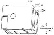
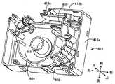
図20は、本発明の他の実施形態である、印刷テープ422自身が熱により発色する感熱(サーマル)タイプのカセット410を正面側すなわち上面から示す斜視図であり、図21は、カセット410を裏面側すなわち下面から示す斜視図である。カセット410は、全体として直方体状を成し、カセット10よりも左右方向の寸法が短く、且つインクリボンロール72および巻取スプール76を備えないが、図18のカセット装着部104と同様に構成されたカセット装着部に着脱可能に装着される。この場合のカセット装着部には、巻取スプール駆動軸108は備えられておらず、ローラ駆動軸110が突設されている。
[Embodiment 2]
FIG. 20 is a perspective view of another embodiment of the present invention, showing athermal type cassette 410 in which theprinting tape 422 itself develops color by heat, from the front side, that is, from the top, and FIG. It is a perspective view showing from the back side, that is, the bottom surface. Thecassette 410 has a rectangular parallelepiped shape as a whole, is shorter in the horizontal direction than thecassette 10, and does not include theink ribbon roll 72 and the take-upspool 76, but is configured in the same manner as thecassette mounting portion 104 in FIG. It is detachably attached to the cassette attachment portion. In this case, the cassette mounting portion is not provided with the take-upspool drive shaft 108, but is provided with theroller drive shaft 110 projecting therefrom.

本実施形態のカセット410は、貼合せテープロール464およびローラ480を備えるが、巻取スプールおよびインクリボンロールは備えられていない。カセット410に備えられた印刷テープ422の被印刷テープ422aは、熱を受けて自己発色する感熱紙から構成されている。カセット410は、カセット10、210と同様に、第1ケース部材412および第2ケース部材414から構成され、内部に形成された第1空間S1に印刷テープロール426を備える第1ケースすなわちテープケース420と、テープケース420の下方側に位置するように装着され、第3ケース部材416および第4ケース部材418から構成され、内部に形成された第2空間S2に貼合せテープロール464を備える第2ケースすなわちケース421とを備えている。第1ケース部材412、第2ケース部材414、第3ケース部材416および第4ケース部材418は、相互に重ねられた状態で、相互の外周壁間にそれぞれ設けられた複数の係止爪427と固定爪428との係合と位置決め突起429による位置決めとによって相互に固定されることにより、カセット410を構成している。Cassette 410 in this embodiment includeslamination tape roll 464 androller 480, but no take-up spool and ink ribbon roll. A print-receivingtape 422a of theprint tape 422 provided in thecassette 410 is composed of heat-sensitive paper that self-colors upon receiving heat. Like thecassettes 10 and 210, thecassette 410 is composed of afirst case member 412 and asecond case member 414. A first case ortape case 420 is provided with aprinting tape roll 426 in a first space S1 formed therein. Asecond tape roll 464 is installed in the lower side of thetape case 420, and is composed of athird case member 416 and afourth case member 418, and is provided with abonding tape roll 464 in a second space S2 formed therein. A case orcase 421 is provided. Thefirst case member 412, thesecond case member 414, thethird case member 416, and thefourth case member 418 are stacked on top of each other, and a plurality of lockingclaws 427 are provided between their outer peripheral walls. Thecassette 410 is configured by being fixed to each other by engagement with the fixing claws 428 and positioning by thepositioning projections 429 .

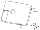
図21において、カセット410の第4ケース部材218の底面には、カセット210が印刷装置102のカセット装着部104に装着されたとき、カセット装着部104に設けられたローラ駆動軸110が差し入れられる、後述のローラ480の軸端がローラ露出穴498を通して、露出させられている。また、第3ケース部材416および第4ケース部材418の側面には、カセット410がカセット装着部104に装着されたとき、カセット装着部104に設けられた後述の印刷ヘッド106が挿入される凹溝411が形成されている。 In FIG. 21, the bottom surface of the fourth case member 218 of thecassette 410 receives theroller drive shaft 110 provided in thecassette mounting portion 104 of theprinting apparatus 102 when the cassette 210 is mounted in thecassette mounting portion 104. A shaft end of aroller 480 to be described later is exposed through aroller exposure hole 498 . Further, on the side surfaces of thethird case member 416 and thefourth case member 418, recessed grooves into which a later-describedprint head 106 provided in thecassette mounting portion 104 is inserted when thecassette 410 is mounted in thecassette mounting portion 104. 411 is formed.

図22は、第1ケース部材412、第2ケース部材414、第3ケース部材416、および第4ケース部材418を分離させて、カセット410の内部構成を説明する斜視図である。図23および図24は、第1ケース部材412の上(正)面側および下(裏)面側を示しており、実施形態2のカセット210の第1ケース部材212と同様に構成されている。図25および図26は、第2ケース部材414の上(正)面側および下(裏)面側を示している。第1ケース部材412の上(正)面側は図4に、第1ケース部材412の下(裏)面側は図5に対応している。図27および図28は、第3ケース部材216の上(正)面側および下(裏)面側を示す図である。図29および図30は第4ケース部材418の上(正)面側および下(裏)面側を示す図である。 FIG. 22 is a perspective view illustrating the internal configuration of thecassette 410 with thefirst case member 412, thesecond case member 414, thethird case member 416, and thefourth case member 418 separated. 23 and 24 show the top (front) side and bottom (back) side of afirst case member 412, which is configured in the same manner as the first case member 212 of the cassette 210 ofEmbodiment 2. . 25 and 26 show the top (front) side and bottom (rear) side of thesecond case member 414. FIG. The upper (front) side of thefirst case member 412 corresponds to FIG. 4, and the lower (rear) side of thefirst case member 412 corresponds to FIG. 27 and 28 are diagrams showing the upper (front) surface side and the lower (rear) surface side of the third case member 216. FIG. 29 and 30 are views showing the top (front) side and the bottom (back) side of thefourth case member 418. FIG.

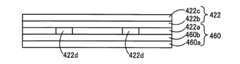
第1ケース部材412と第2ケース部材414との間には、印刷テープ422が円筒状の軸芯材である印刷テープスプール424に巻回された印刷テープロール426を上下方向に平行な第1回転中心線C1まわりに回転可能に収容する第1空間S1が形成されている。上下方向とは、第1ケース部材412から第4ケース部材418の積重ね方向である第1方向に対応し、上方向とは第1ケース部材212側へ向かう方向、下方向とは第4ケース部材218へ向かう方向を示している。第1ケース部材412および第2ケース部材214は長方形状であって、第1回転中心線C1は長手方向の中心からやや下偏心した位置に設けられている。印刷テープ422は印刷ヘッド106によって印刷される第1テープに対応し、印刷テープロール426は第1ロールに対応し、印刷テープスプール424は第1スプールに対応している。印刷テープ422は、たとえば図32に示すように、基材としての被印刷テープ422aの印刷面とは反対側の面に、剥離テープ422cが粘着剤422bを介して積層されることにより構成されたものである。本実施形態では、被印刷テープ422aは、加熱によってたとえば黒色に自己発色する感熱材料から構成されており、図32の被印刷テープ422aの一部には、局所発色領域422dが示されている。 Between thefirst case member 412 and thesecond case member 414, aprinting tape roll 426 wound on aprinting tape spool 424, which is a cylindrical shaft core member, is placed in a vertically parallel firstprinting tape roll 426. A first space S1 rotatably accommodated is formed around the rotation center line C1. The vertical direction corresponds to the first direction in which thefirst case member 412 and thefourth case member 418 are stacked, the upward direction is the direction toward the first case member 212, and the downward direction is the fourth case member. 218 is shown. Thefirst case member 412 and the second case member 214 are rectangular, and the first rotation center line C1 is provided at a position slightly eccentric downward from the center in the longitudinal direction.Printing tape 422 corresponds to the first tape printed byprinthead 106, printingtape roll 426 corresponds to the first roll, andprinting tape spool 424 corresponds to the first spool. Theprinting tape 422, for example, as shown in FIG. 32, is constructed by laminating arelease tape 422c via an adhesive 422b on the surface opposite to the printing surface of aprinting tape 422a as a base material. It is. In this embodiment, the print-receivingtape 422a is composed of a thermosensitive material that self-colors, for example, black when heated, and alocalized coloring region 422d is shown in a portion of the print-receivingtape 422a in FIG.

図24、図25に示すように、第1ケース部材412の下面側および第2ケース部材414の上面側には、印刷テープスプール424の上端および他端に回転可能に嵌合して印刷テープロール426を回転可能に支持する円筒状の第1支持突起430および第2支持突起432と、未使用状態の印刷テープロール426の外径よりも大きい内径を有する第1円周壁434および第2円周壁436とが、第1回転中心線C1と同じ中心線を有する状態で突設されている。印刷テープスプール424は、第1円周壁434および第2円周壁436内に回転可能に保持された状態で、印刷テープロール426の外径と同じ外径を有する円形のスペーサフィルム438をそれぞれ介在させた状態で第1ケース部材412と第2ケース部材414との間に配設されている。 As shown in FIGS. 24 and 25, the lower surface side of thefirst case member 412 and the upper surface side of thesecond case member 414 are rotatably fitted to the upper end and the other end of theprinting tape spool 424 to hold the printing tape rolls. 426 rotatably supporting cylindricalfirst support protrusion 430 and second support protrusion 432 , and first and secondcircumferential walls 434 and 434 having inner diameters larger than the outer diameter of the unusedprinting tape roll 426 . 436 protrudes with the same center line as the first rotation center line C1. Theprinting tape spool 424 is rotatably held within a firstcircumferential wall 434 and a secondcircumferential wall 436 with interveningcircular spacer films 438 each having an outer diameter the same as the outer diameter of theprinting tape roll 426 . It is disposed between thefirst case member 412 and thesecond case member 414 in a folded state.

図25に示すように、第2ケース部材414の底板414aには、第2円周壁436と外周壁446の短辺部446aおよび長辺部446bとの間に沿って長手状に形成された第3開口である貫通穴452と、第2円周壁436のうち短辺部446aおよび長辺部446bの角部と対向する部分と貫通穴452との間においてリブ先端縁454aの外接面がテーパ面となるように形成された複数の案内リブ454とが、形成されている。複数の案内リブ454のリブ先端縁454aの外接面が形成するテーパ面は、印刷テープロール426から巻き出され印刷テープ422を貫通穴452内へ導くためのものである。これにより、印刷テープ422は、第1層L1および第1空間S1と第2層L2および第2空間内S2との間の隔壁として機能する底板414aに形成された貫通穴452を通して、テープケース420と下ケース421とに架け渡されている。 As shown in FIG. 25, abottom plate 414a of thesecond case member 414 has a secondcircumferential wall 436 formed longitudinally between theshort side portion 446a and thelong side portion 446b of the outercircumferential wall 446. The circumscribing surface of therib leading edge 454a is tapered between the throughhole 452 having three openings and the portion of the secondcircumferential wall 436 facing the corners of theshort side portion 446a and thelong side portion 446b and the throughhole 452. A plurality ofguide ribs 454 are formed so as to be formed. A tapered surface formed by the circumscribing surfaces of theleading edges 454 a of the plurality ofguide ribs 454 guides theprinting tape 422 unwound from theprinting tape roll 426 into the throughhole 452 . As a result, theprinting tape 422 passes through the throughhole 452 formed in thebottom plate 414a that functions as a partition wall between the first layer L1 and the first space S1 and the second layer L2 and the second space S2, and thetape case 420. and thelower case 421 .

図26および図27において、第2ケース部材414の底板414aおよび第3ケース部材416の天井板416eは、テープケース420内の第1空間S1と下ケース421内の第2空間S2とを区画する板材或いは隔壁に対応している。 26 and 27, thebottom plate 414a of thesecond case member 414 and theceiling plate 416e of thethird case member 416 separate the first space S1 in thetape case 420 and the second space S2 in thelower case 421. It corresponds to a plate material or a partition wall.

図28は、第3ケース部材416の下面側を示している。第3ケース部材416の下面には、貼合せテープロール464を保持する貼合ロール保持壁484と、貼合せテープロール464の貼合せスプール462を嵌め入れてそれを回転可能に支持する円筒状突起466とが、形成されている。貼合ロール保持壁484は、貼合せスプール462を保持するために円筒状突起466と同心の円弧状に形成されている。 28 shows the bottom side of thethird case member 416. FIG. On the lower surface of thethird case member 416, a bondingroll holding wall 484 that holds thebonding tape roll 464 and a cylindrical projection that fits thebonding spool 462 of thebonding tape roll 464 and rotatably supports it. 466 are formed. The laminatingroll retaining wall 484 is arcuately formed concentrically with thecylindrical projection 466 to retain thelaminating spool 462 .

図29および図30は、第4ケース部材218の上面および下面を示している。図29および図30において、円筒状突起466によって回転可能に支持された貼合せテープロール464の貼合せスプール462の第4ケース部材218側の端部を嵌め入れてそれを回転可能に支持する貼合せスプール支持穴494が第4ケース部材218を貫通して形成されている。また、第4ケース部材218には、ローラ480の第4ケース部材218側の端部を嵌め入れてそれを回転可能に支持するとともに、ローラ480の第4ケース部材218側の軸端を露出させて、ローラ駆動軸110と連結可能とするローラ露出穴498が、貫通状態で設けられている。 29 and 30 show the upper and lower surfaces of the fourth case member 218. FIG. 29 and 30, the end of thelamination spool 462 of thelamination tape roll 464 rotatably supported by thecylindrical protrusion 466 is fitted into thelamination spool 462 to rotatably support it. A matingspool support hole 494 is formed through the fourth case member 218 . Further, the end of theroller 480 on the side of the fourth case member 218 is fitted into the fourth case member 218 to rotatably support it, and the shaft end of theroller 480 on the side of the fourth case member 218 is exposed. Aroller exposing hole 498 is provided in a penetrating state so as to be connectable with theroller drive shaft 110 .

図31は、第3ケース部材416の下面を示す図を用いて、印刷テープロール426から引き出される印刷テープ422、および貼合せテープロール464から引き出される貼合せテープ460の経路を、それぞれ説明している。カセット410がローラ駆動軸110が立設されたカセット装着部104に装着されたとき、ローラ駆動軸110により回転駆動されるローラ480が印刷テープ422および貼合せテープ460を挟圧しつつ送ることにより、印刷ヘッド106とプラテンローラ116との間において印刷テープ422が印刷テープロール426から引き出され、排出口500から排出される。図32では、印刷テープ422の経路と、貼合せテープ460の経路とが、1点鎖線および破線でそれぞれ示されている。 FIG. 31 illustrates the paths of theprinting tape 422 drawn from theprinting tape roll 426 and thelamination tape 460 drawn from thelamination tape roll 464, using a view showing the lower surface of thethird case member 416. there is When thecassette 410 is mounted on thecassette mounting portion 104 on which theroller drive shaft 110 is erected, theroller 480 rotationally driven by theroller drive shaft 110 pinches and feeds theprint tape 422 and thebonding tape 460. Between theprint head 106 and theplaten roller 116 , theprint tape 422 is pulled from theprint tape roll 426 and ejected from theejection port 500 . In FIG. 32, the path of theprinting tape 422 and the path of thelaminating tape 460 are indicated by dashed-dotted lines and dashed lines, respectively.

印刷ヘッド106とプラテンローラ116との間の印刷場所Pでは、印刷テープ422が印刷ヘッド106に押しつけられた状態で、印刷ヘッド106の表面に配置された複数の発熱素子が選択的に駆動されて局所発熱すると、印刷テープ422の被印刷テープ422aが自己発色することで、印刷テープ422に文字、記号などが印刷される。 At a print location P between theprint head 106 and theplaten roller 116, a plurality of heating elements disposed on the surface of theprint head 106 are selectively driven while theprint tape 422 is pressed against theprint head 106. When the local heat is generated, the printedtape 422a of theprinting tape 422 self-colors, and characters, symbols, etc. are printed on theprinting tape 422. FIG.

図32は、カセット410から送り出された印刷テープ422の積層構造体を示している。印刷テープ422は、被印刷テープ422aと、被印刷テープ422aの非印刷面側に粘着剤422bを介して貼り着けられた剥離テープ422cとの積層体である。被印刷テープ422aには、局所発色領域422dが形成されている。印刷テープ422の基材としての被印刷テープ422aには、貼合せテープ460の透明フィルム460aが粘着剤460bを介して積層されている。 FIG. 32 shows a laminated structure ofprint tape 422 fed fromcassette 410 . Theprinting tape 422 is a laminate of aprinting tape 422a and a peelingtape 422c attached to the non-printing surface of theprinting tape 422a via an adhesive 422b. Alocal coloring region 422d is formed on the print-receivingtape 422a. Atransparent film 460a of abonding tape 460 is laminated on a printedtape 422a as a base material of theprinting tape 422 via an adhesive 460b.

図33では、印刷テープロール426、および、貼合せテープロール464は、それぞれ未使用の初期状態の大きさを示している。第3ケース部材416と第4ケース部材418との間の第2空間S2内すなわち下ケース421内に収容された貼合せテープロール464が実線で示され、それに上下方向に重ねて、第1ケース部材412と第2ケース部材414との間の第1空間S1内すなわちテープケース420内に収容された印刷テープロール426およびそれと同径のスペーサフィルム438が、第2空間S2内で上下方向に直交する投影面上に一点鎖線(仮想線)で示されている。図33は未使用すなわち初期状態の印刷テープロール426、貼合せテープロール464を示している。図33に示されるように、未使用すなわち初期状態の印刷テープロール426の径は、貼合せテープロール464の径よりも大きい。 In FIG. 33, theprinting tape roll 426 and thelaminating tape roll 464 each show the size of an unused initial state. Thelamination tape roll 464 accommodated in the second space S2 between thethird case member 416 and thefourth case member 418, i.e., thelower case 421, is indicated by a solid line. Aprinting tape roll 426 and aspacer film 438 having the same diameter accommodated in the first space S1 between themember 412 and thesecond case member 414, that is, thetape case 420, are perpendicular to the vertical direction in the second space S2. It is indicated by a one-dot chain line (virtual line) on the projection plane. FIG. 33 shows theprinting tape roll 426 and thelaminating tape roll 464 in an unused or pristine condition. As shown in FIG. 33, the diameter of the virgin or pristineprinting tape roll 426 is greater than the diameter of thelaminating tape roll 464 .

図33において、印刷テープロール426は、貼合せテープロール464の第2回転中心線C2と上下方向すなわち第1方向において重なっている。換言すれば、印刷テープロール426の投影面の中に、貼合せテープロール464の少なくとも一部および第2回転中心線C2が上下方向すなわち第1方向において重なっている。また、貼合せテープロール464の少なくとも一部および第2回転中心線C2は、印刷テープロール426およびスペーサフィルム438と上下方向すなわち第1方向に重なっている。すなわち、貼合せテープロール464の少なくとも一部および第2回転中心線C2は、印刷テープロール426およびスペーサフィルム438の投影面の中に位置している。 In FIG. 33, theprinting tape roll 426 overlaps the second rotational centerline C2 of thelamination tape roll 464 in the vertical or first direction. In other words, in the projection plane of theprinting tape roll 426, at least a portion of thelamination tape roll 464 and the second rotation centerline C2 overlap in the vertical direction, ie, the first direction. Also, at least a portion of thelamination tape roll 464 and the second rotation centerline C2 overlap theprinting tape roll 426 and thespacer film 438 in the vertical direction, that is, in the first direction. That is, at least a portion of thelamination tape roll 464 and the second centerline of rotation C2 are located in the plane of projection of theprinting tape roll 426 and thespacer film 438 .

図33に示すように、貼合せテープロール464の一部、貼合せスプール462、およびそれらの回転中心である第2回転中心線C2と、カセット410の中心位置Mとは、印刷テープロール426とそれぞれ上下方向(第1方向)において重なっていて、印刷テープロール426の投影面の中に位置している。また、貼合せテープロール464および貼合せスプール62の一部と、後述のカセット410の中心位置Mとは、それぞれ上下方向(第1方向)において印刷テープスプール424と重なっていて、印刷テープスプール424の投影面の中に位置している。このような位置関係から明らかなように、印刷テープロール426の少なくとも一部は、貼合せテープロール464の少なくとも一部と、第1回転中心線C1と平行な第1方向において重なっている。 As shown in FIG. 33, a portion of thelamination tape roll 464, thelamination spool 462, the second rotation center line C2 as their rotation centers, and the center position M of thecassette 410 are aligned with theprinting tape roll 426. They overlap each other in the vertical direction (first direction) and are located in the projection plane of theprinting tape roll 426 . Also, thebonding tape roll 464 and a part of thebonding spool 62 and the center position M of the later-describedcassette 410 overlap theprinting tape spool 424 in the vertical direction (first direction). is located in the projection plane of As is clear from such a positional relationship, at least a portion of theprinting tape roll 426 overlaps at least a portion of thelamination tape roll 464 in the first direction parallel to the first rotation centerline C1.

以上のように構成された本実施態様のカセット410によれば、第1層L1に配置され、印刷される印刷テープ(第1テープ)422が巻回されて構成される印刷テープロール(第1ロール)426と、第2層L2に配置され、印刷テープ(第1テープ)422に貼り合わされる貼合せテープ(第2テープ)460が巻回されて構成される貼合せテープロール(第2ロール)464とを備えた2層構造のカセット410であって、印刷テープロール426の少なくとも一部は、貼合せテープロール464の少なくとも一部と、印刷テープロール426の回転中心である第1回転中心線C1と平行な第1方向に重なっている。これにより、カセット410は、印刷テープロール426の少なくとも一部が、貼合せテープロール464の少なくとも一部と第1方向に重なっていない場合よりも、小型化が可能となる。 According to thecassette 410 of the present embodiment configured as described above, the printing tape roll (first tape) 422 is arranged on the first layer L1 and is wound with the printing tape (first tape) 422 to be printed. roll) 426 and a bonding tape roll (second roll) 460 disposed on the second layer L2 and bonded to the printing tape (first tape) 422 are wound. ) 464, wherein at least a portion of theprinting tape roll 426 includes at least a portion of thelamination tape roll 464 and a first rotation center around which theprinting tape roll 426 rotates. It overlaps in a first direction parallel to line C1. This allows thecassette 410 to be made smaller than when at least a portion of theprinting tape roll 426 does not overlap at least a portion of thelamination tape roll 464 in the first direction.

本実施形態のカセット410によれば、印刷テープロール(第1ロール)426の少なくとも一部と貼合せスプール(第2スプール)462の少なくとも一部とが第1方向に重なる。これにより、カセット410は、印刷テープロール426の少なくとも一部と貼合せスプール462の少なくとも一部とが第1方向に重ならない場合よりも、小型化が可能となる。 According to thecassette 410 of the present embodiment, at least part of the printing tape roll (first roll) 426 and at least part of the bonding spool (second spool) 462 overlap in the first direction. This allows thecassette 410 to be made smaller than if at least a portion of theprinting tape roll 426 and at least a portion of thelamination spool 462 did not overlap in the first direction.

本実施形態のカセット410によれば、印刷テープスプール(第1スプール)424の少なくとも一部と貼合せテープロール(第2ロール)464の少なくとも一部とが第1方向に重なる。これにより、カセット410は、印刷テープスプール424の少なくとも一部と貼合せテープロール464の少なくとも一部とが第1方向に重ならない場合よりも、小型化が可能となる。 According to thecassette 410 of this embodiment, at least a portion of the printing tape spool (first spool) 424 and at least a portion of the bonding tape roll (second roll) 464 overlap in the first direction. This allows thecassette 410 to be made smaller than if at least a portion of theprinting tape spool 424 and at least a portion of thelaminating tape roll 464 do not overlap in the first direction.

本実施形態のカセット410によれば、印刷テープスプール(第1スプール)424の少なくとも一部と貼合せスプール(第2スプール)462の少なくとも一部とが第1方向に重なる。これにより、カセット410は、印刷テープスプール424の少なくとも一部と貼合せスプール462の少なくとも一部とが第1方向に重ならない場合よりも、小型化が可能となる。 According to thecassette 410 of the present embodiment, at least part of the printing tape spool (first spool) 424 and at least part of the bonding spool (second spool) 462 overlap in the first direction. This allows thecassette 410 to be made smaller than when at least a portion of theprinting tape spool 424 and at least a portion of thelamination spool 462 do not overlap in the first direction.

本実施形態のカセット410によれば、印刷テープロール(第1ロール)426と貼合せテープロール(第2ロール)464の第2回転中心線C2とが第1方向に重なる。これにより、カセット410は、第1ロールと第2ロールの回転中心とが第1方向に重ならない場合よりも、小型化が可能となる。 According to thecassette 410 of the present embodiment, the printing tape roll (first roll) 426 and the bonding tape roll (second roll) 464 overlap the second rotation center line C2 in the first direction. Thereby, thecassette 410 can be made smaller than when the rotation centers of the first roll and the second roll do not overlap in the first direction.

本実施形態のカセット410によれば、印刷テープロール(第1ロール)426の第1回転中心線C1と貼合せテープロール(第2ロール)464とが第1方向に重なる。これにより、カセット410は、印刷テープロール426の第1回転中心線C1と貼合せテープロール464とが第1方向に重ならない場合よりも、小型化が可能となる。 According to thecassette 410 of this embodiment, the first rotation center line C1 of the printing tape roll (first roll) 426 and the bonding tape roll (second roll) 464 overlap in the first direction. As a result, thecassette 410 can be made smaller than when the first rotation center line C1 of theprinting tape roll 426 and thebonding tape roll 464 do not overlap in the first direction.

本実施形態のカセット410によれば、印刷テープロール(第1ロール)426とカセット410の平面視での中心位置Mとが第1方向に重なる。これにより、カセット410は、印刷テープロール426とカセット410の中心位置Mとが第1方向に重ならない場合よりも、小型化が可能となる。 According to thecassette 410 of the present embodiment, the printing tape roll (first roll) 426 and the central position M of thecassette 410 in plan view overlap in the first direction. As a result, thecassette 410 can be made smaller than when theprint tape roll 426 and the center position M of thecassette 410 do not overlap in the first direction.

なお、上述したのはあくまでも本発明の一実施態様であり、本発明はその趣旨を逸脱しない範囲において、当業者の知識に基づいて種々の変更が加えられ得る。 It should be noted that what has been described above is merely one embodiment of the present invention, and various modifications can be made to the present invention based on the knowledge of those skilled in the art without departing from the spirit of the present invention.

10、410:カセット
11:凹溝(ヘッド開口)
12、412:第1ケース部材
14、414:第2ケース部材
16、416:第3ケース部材
18、418:第4ケース部材
20、420:テープケース(第1層)
21、421:下ケース(第2層)
22、422:印刷テープ(被印刷媒体、第1テープ)
22a、422a:被印刷テープ
22b、422b:粘着剤
22c、422c:剥離テープ
24、424:印刷テープスプール(第1スプール)
26、426:印刷テープロール(第1ロール)
27、427:係止爪
28、428:固定爪
29、429:位置決め突起
30、430:第1支持突起
32、432:第2支持突起
34、434:第1円周壁
36、436:第2円周壁
38、438:スペーサフィルム
40、440:印刷テープゲート
42、442:印刷テープゲート
44、444:第1ケース部材の外周壁
46、446:第2ケース部材の外周壁
46a、446a:短辺部
46b、446b:長辺部
50、450:案内壁
52、452:貫通穴
54、454:案内リブ
54a、454a:リブ先端縁
56、456:案内壁
58、458:貫通穴
60、460:貼合せテープ(第2テープ)
60a、460a:透明フィルム(透明な媒体)
60b、460b:粘着剤
62、462:貼合せスプール(第2スプール)
64、464:貼合せテープロール(第2ロール)
66:貼合せテープロール支持穴
68:インクリボン(第3テープ)
68a、468a:インク
70:供給スプール(第3スプール)
72:インクリボンロール(第3ロール)
74:インクリボン支持穴
76、476:巻取スプール
78:巻取スプール支持穴
80、480:ローラ
80a:連結部
82、482:ローラ支持穴
84、484:貼合せテープロール保持壁
86:インクリボンロール保持壁
88:円筒状突起
90:クラッチばねホルダ
92:円弧状壁
94:巻取スプール支持穴
96:連結穴
98:ローラ露出穴
102:印刷装置
104:カセット装着部
106:印刷ヘッド
108:巻取スプール駆動軸
110:ローラ駆動軸
112:位置決め穴
114:ヘッド保持板
116:プラテンローラ
118:押圧ローラ
120:プラテン保持部材
122:印刷システム
466:円筒状突起
L1:第1層
L2:第2層
S1:第1空間
S2:第2空間
C1:第1回転中心線(第1ロールの回転中心)
C2:第2回転中心線(第2ロールの回転中心)
C3:第3回転中心線
C4:第4回転中心線
C5:第5回転中心線
SL1:第1直線
SL2:第2直線
10, 410: Cassette 11: Groove (head opening)
12, 412:first case member 14, 414:second case member 16, 416:third case member 18, 418:fourth case member 20, 420: tape case (first layer)
21, 421: lower case (second layer)
22, 422: printing tape (printing medium, first tape)
22a, 422a: printedtapes 22b, 422b: adhesive 22c, 422c:release tapes 24, 424: printing tape spool (first spool)
26, 426: Printing tape roll (first roll)
27, 427: lockingclaws 28, 428: fixingclaws 29, 429: positioningprojections 30, 430: first supportingprojections 32, 432: second supportingprojections 34, 434: firstcircumferential wall 36, 436: second circlePeripheral walls 38, 438:Spacer films 40, 440: Printedtape gates 42, 442: Printedtape gates 44, 444:Peripheral walls 46, 446 of the first case member:Peripheral walls 46a, 446a of the second case member:Short sides 46b, 446b:long sides 50, 450: guidewalls 52, 452: throughholes 54, 454: guideribs 54a, 454a: rib tip edges 56, 456: guidewalls 58, 458: throughholes 60, 460: bonding Tape (second tape)
60a, 460a: transparent film (transparent medium)
60b, 460b: Adhesive 62, 462: Lamination spool (second spool)
64, 464: Lamination tape roll (second roll)
66: Bonding tape roll support hole 68: Ink ribbon (third tape)
68a, 468a: Ink 70: Supply spool (third spool)
72: Ink ribbon roll (third roll)
74: Ink ribbon support holes 76, 476: Winding spool 78: Winding spool support holes 80, 480:Roller 80a: Connectingparts 82, 482: Roller support holes 84, 484: Bonding tape roll holding wall 86: Ink ribbon Roll holding wall 88: Cylindrical protrusion 90: Clutch spring holder 92: Arc wall 94: Winding spool support hole 96: Connection hole 98: Roller exposure hole 102: Printing device 104: Cassette mounting part 106: Print head 108: Roll Take-up spool drive shaft 110: Roller drive shaft 112: Positioning hole 114: Head holding plate 116: Platen roller 118: Pressure roller 120: Platen holding member 122: Printing system 466: Cylindrical protrusion L1: First layer L2: Second layer S1: First space S2: Second space C1: First rotation center line (rotation center of first roll)
C2: Second rotation center line (rotation center of second roll)
C3: Third rotation center line C4: Fourth rotation center line C5: Fifth rotation center line SL1: First straight line SL2: Second straight line

Claims (19)

Translated fromJapanese
刷される第1テープが巻回されて構成される第1ロールと、
粘着層を有する第2テープが巻回されて構成される第2ロールと、
前記第1テープと前記第2テープとを前記粘着層を介して貼り合わせるための挟圧部材と、を備え
前記第1ロールは、その少なくとも一部前記第1ロールの回転中心線と平行な第1方向に沿う方向にみたときに前記第2ロールの少なくとも一部と重なる位置に配置されていることを特徴とするカセット。
a first roll configured by winding a first tape to beprinted ;
a second roll configured by winding a second tapehaving an adhesive layer ;
A pinching member for bonding the first tape and the second tape together via the adhesive layer,
At least partofthe first roll isarranged at a position overlapping at least part ofthesecond roll when viewed in a first direction parallel to the rotation center line of the first roll. A cassette characterized by:
前記挟圧部材は、ローラであることを特徴とする請求項1に記載のカセット。2. A cassette according to claim 1, wherein said pinching member is a roller .前記ローラは、前記第2テープと接触可能に配置されていることを特徴とする請求項2に記載のカセット。3. A cassette according to claim 2, wherein said roller is arranged to be in contact with said second tape. 前記カセットは、第1層と第2層とが前記第1方向に積層された構成を有し、 The cassette has a configuration in which a first layer and a second layer are laminated in the first direction,
前記第1ロールは、前記第1層に配置され、 The first roll is arranged on the first layer,
前記第2ロールは、前記第2層に配置され、 The second roll is arranged on the second layer,
前記挟圧部材は、前記第2層に配置されることを特徴とする請求項1に記載のカセット。 2. The cassette according to claim 1, wherein said pinching member is arranged on said second layer.
前記第1テープの印刷に使用されるインクリボンが巻回された第3ロールを有し、
前記第3ロールは、少なくとも一部が、前記第1方向に沿う方向にみたときに前記第1ロールの少なくとも一部と重なる位置に配置されている
ことを特徴とする請求項1に記載のカセット。
Having a third roll around which an ink ribbon used for printing the first tape is wound,
2. The cassette according to claim1, wherein at least part of said third roll overlaps at least part of said first roll when viewed along said first direction. .
前記第2層に配置され、前記第1テープの印刷に使用されるインクリボンが巻き取られる巻取スプールを有し、
前記第1ロールと、前記巻取スプールの少なくとも一部とが、前記第1方向に沿う方向にみたときに重なる
ことを特徴とする請求項に記載のカセット。
a take-up spool disposed on the second layer and on which an ink ribbon used for printing the first tape is taken up;
5. The cassette according to claim4 , wherein the first roll and at least a portion of the take-up spool overlapwhen viewed along the first direction.
前記第1テープの印刷に使用されるインクリボンが巻回された第3スプールと、前記インクリボンが巻き取られる巻取スプールとを備え、
前記第1ロールの回転中心は、前記第2ロールの回転中心と前記第3スプールの回転中心あるいは前記巻取スプールの回転中心との間にある
ことを特徴とする請求項1に記載のカセット。
A third spool on which an ink ribbon used for printing the first tape is wound, and a winding spool on which the ink ribbon is wound,
2. The cassette according to claim 1, wherein the center of rotation of the first roll is between the center of rotation of the second roll and the center of rotation of the third spool or the center of rotation of the take-up spool.
前記第1ロールの回転中心は、前記第2ロールと前記第3ロールとの凸包絡の中にある
ことを特徴とする請求項に記載のカセット。
6. The cassette according to claim5 , wherein the center of rotation of said first roll is in a convex envelope between said second roll and said third roll.
前記第1テープが巻回された第1スプールの少なくとも一部と、前記第2テープが巻回された第2スプールの少なくとも一部と、前記インクリボンが巻回された第3スプールの少なくとも一部は、第1直線上に並ぶ
ことを特徴とする請求項5又は6に記載のカセット。
At least a portion of a first spool around which the first tape is wound, at least a portion of a second spool around which the second tape is wound, and at least one of a third spool around which the ink ribbon is wound. 7. A cassette according to claim5 or 6 , characterized in that the parts are arranged on the first straight line.
前記インクリボンが巻き取られる巻取スプールと、ヘッド開口が更に設けられ、
前記巻取スプールと前記ヘッド開口とは、前記第1直線を挟む位置に配置されている
ことを特徴とする請求項に記載のカセット。
A winding spool on which the ink ribbon is wound and a head opening are further provided,
10. The cassette according to claim9 , wherein the take-up spool and the head opening are arranged at positions sandwiching the first straight line.
前記インクリボンが巻き取られる巻取スプールが更に設けられ、
前記巻取スプールの少なくとも一部と前記第1ロールの回転中心とを結ぶ第2直線は、前記第1直線と直交する
ことを特徴とする請求項に記載のカセット。
A winding spool on which the ink ribbon is wound is further provided,
10. The cassette according to claim9 , wherein a second straight line connecting at least a portion of the take-up spool and the center of rotation of the first roll is perpendicular to the first straight line.
前記第1ロールの直径は、前記第2ロール及び前記第3ロールの直径より大きい
ことを特徴とする請求項5に記載のカセット。
6. The cassette of claim 5, wherein the diameter of the first roll is greater than the diameters of the second roll and the third roll.
前記第1ロールの回転中心線方向と、前記第2ロールの回転中心線方向と、前記第3ロールの回転中心線方向は、前記第1方向と平行である
ことを特徴とする請求項5、8または12に記載のカセット。
5, wherein the rotation center line direction of the first roll, the rotation center line direction of the second roll, and the rotation center line direction of the third roll are parallel to the first direction, The cassette according to8 or 12 .
前記第2テープが巻回された第2スプールを備え、
前記第1ロールの少なくとも一部と前記第2スプールの少なくとも一部とが前記第1方向に沿う方向にみたときに重なる
ことを特徴とする請求項1のカセット。
A second spool around which the second tape is wound,
2. The cassette according to claim 1, wherein at least a portion of said first roll and at least a portion of said second spool overlapwhen viewed along said first direction.
前記第1テープが巻回された第1スプールを備え、
前記第1スプールの少なくとも一部と前記第2ロールの少なくとも一部とが前記第1方向に沿う方向にみたときに重なる
ことを特徴とする請求項1のカセット。
A first spool on which the first tape is wound,
2. The cassette according to claim 1, wherein at least a portion of said first spool and at least a portion of said second roll overlapwhen viewed along said first direction.
前記第1テープが巻回された第1スプールと、前記第2テープが巻回された第2スプールとを備え、
前記第1スプールの少なくとも一部と前記第2スプールの少なくとも一部とが前記第1方向に沿う方向にみたときに重なる
ことを特徴とする請求項1のカセット。
A first spool around which the first tape is wound and a second spool around which the second tape is wound,
2. The cassette according to claim 1, wherein at least a portion of said first spool and at least a portion of said second spool overlapwhen viewed along said first direction.
前記第1ロールと前記第2ロールの回転中心とが前記第1方向に沿う方向にみたときに重なる
ことを特徴とする請求項1のカセット。
2. The cassette according to claim 1, wherein the centers of rotation of said first roll and said second roll overlap eachother when viewed along said first direction.
前記第1ロールの回転中心と前記第2ロールとが前記第1方向に沿う方向にみたときに重なる
ことを特徴とする請求項1のカセット。
2. The cassette according to claim 1, wherein the center of rotation of said first roll and said second roll overlapwhen viewed along said first direction.
前記第1ロールと前記カセットの中心とが前記第1方向に沿う方向にみたときに重なる
ことを特徴とする請求項1のカセット。
2. The cassette according to claim 1, wherein said first roll and the center of said cassette overlapwhen viewed along said first direction.
JP2019069564A2019-03-312019-03-31 cassetteActiveJP7200805B2 (en)

Priority Applications (2)

Application NumberPriority DateFiling DateTitle
JP2019069564AJP7200805B2 (en)2019-03-312019-03-31 cassette
PCT/JP2020/011094WO2020203179A1 (en)2019-03-312020-03-13Cassette

Applications Claiming Priority (1)

Application NumberPriority DateFiling DateTitle
JP2019069564AJP7200805B2 (en)2019-03-312019-03-31 cassette

Publications (2)

Publication NumberPublication Date
JP2020168728A JP2020168728A (en)2020-10-15
JP7200805B2true JP7200805B2 (en)2023-01-10

Family

ID=72668352

Family Applications (1)

Application NumberTitlePriority DateFiling Date
JP2019069564AActiveJP7200805B2 (en)2019-03-312019-03-31 cassette

Country Status (2)

CountryLink
JP (1)JP7200805B2 (en)
WO (1)WO2020203179A1 (en)

Citations (2)

* Cited by examiner, † Cited by third party
Publication numberPriority datePublication dateAssigneeTitle
JP2004255656A (en)2003-02-252004-09-16Seiko Epson Corp Tape cartridges and tape printers
JP2011037223A (en)2009-08-182011-02-24Seiko Epson CorpTape cartridge

Family Cites Families (3)

* Cited by examiner, † Cited by third party
Publication numberPriority datePublication dateAssigneeTitle
US4279390A (en)*1979-10-181981-07-21Wang Laboratories, Inc.Ribbon cartridge
JPS63156762U (en)*1987-04-021988-10-14
JP3693429B2 (en)*1996-08-202005-09-07株式会社キングジム Tape printer

Patent Citations (2)

* Cited by examiner, † Cited by third party
Publication numberPriority datePublication dateAssigneeTitle
JP2004255656A (en)2003-02-252004-09-16Seiko Epson Corp Tape cartridges and tape printers
JP2011037223A (en)2009-08-182011-02-24Seiko Epson CorpTape cartridge

Also Published As

Publication numberPublication date
WO2020203179A1 (en)2020-10-08
JP2020168728A (en)2020-10-15

Similar Documents

PublicationPublication DateTitle
JP7647956B2 (en) cassette
JP7567995B2 (en) cassette
JP7711733B2 (en) cassette
JP7272063B2 (en) cassette
JP7200805B2 (en) cassette
JP7200806B2 (en) cassette
JP7188238B2 (en) cassette

Legal Events

DateCodeTitleDescription
A621Written request for application examination

Free format text:JAPANESE INTERMEDIATE CODE: A621

Effective date:20220322

A131Notification of reasons for refusal

Free format text:JAPANESE INTERMEDIATE CODE: A131

Effective date:20220906

A521Request for written amendment filed

Free format text:JAPANESE INTERMEDIATE CODE: A523

Effective date:20221104

TRDDDecision of grant or rejection written
A01Written decision to grant a patent or to grant a registration (utility model)

Free format text:JAPANESE INTERMEDIATE CODE: A01

Effective date:20221122

A61First payment of annual fees (during grant procedure)

Free format text:JAPANESE INTERMEDIATE CODE: A61

Effective date:20221205

R150Certificate of patent or registration of utility model

Ref document number:7200805

Country of ref document:JP

Free format text:JAPANESE INTERMEDIATE CODE: R150


[8]ページ先頭

©2009-2025 Movatter.jp