JP7200013B2 - Tunnel Face Forward Exploration System and Tunnel Face Forward Exploration Method - Google Patents
Tunnel Face Forward Exploration System and Tunnel Face Forward Exploration MethodDownload PDFInfo
- Publication number
- JP7200013B2 JP7200013B2JP2019042521AJP2019042521AJP7200013B2JP 7200013 B2JP7200013 B2JP 7200013B2JP 2019042521 AJP2019042521 AJP 2019042521AJP 2019042521 AJP2019042521 AJP 2019042521AJP 7200013 B2JP7200013 B2JP 7200013B2
- Authority
- JP
- Japan
- Prior art keywords
- drilling
- rod
- sensor
- vibration
- bit
- Prior art date
- Legal status (The legal status is an assumption and is not a legal conclusion. Google has not performed a legal analysis and makes no representation as to the accuracy of the status listed.)
- Active
Links
- 238000000034methodMethods0.000titleclaimsdescription24
- 238000005553drillingMethods0.000claimsdescription171
- 238000009412basement excavationMethods0.000claimsdescription37
- 239000002184metalSubstances0.000claimsdescription15
- 230000002093peripheral effectEffects0.000claimsdescription10
- 238000004891communicationMethods0.000claimsdescription5
- XLYOFNOQVPJJNP-UHFFFAOYSA-NwaterSubstancesOXLYOFNOQVPJJNP-UHFFFAOYSA-N0.000description23
- 238000012545processingMethods0.000description15
- 125000006850spacer groupChemical group0.000description15
- 239000012530fluidSubstances0.000description13
- 230000006870functionEffects0.000description8
- 230000010355oscillationEffects0.000description6
- 238000007405data analysisMethods0.000description5
- 238000003825pressingMethods0.000description5
- 238000004458analytical methodMethods0.000description4
- 238000004364calculation methodMethods0.000description4
- 238000010276constructionMethods0.000description4
- 239000004020conductorSubstances0.000description3
- 230000033001locomotionEffects0.000description3
- 238000005259measurementMethods0.000description3
- 239000002245particleSubstances0.000description3
- 238000005422blastingMethods0.000description2
- 238000010586diagramMethods0.000description2
- 239000004519greaseSubstances0.000description2
- 230000005540biological transmissionEffects0.000description1
- 238000013461designMethods0.000description1
- 239000012777electrically insulating materialSubstances0.000description1
- 238000005516engineering processMethods0.000description1
- 238000012905input functionMethods0.000description1
- 238000003780insertionMethods0.000description1
- 230000037431insertionEffects0.000description1
- 238000009434installationMethods0.000description1
- 239000011810insulating materialSubstances0.000description1
- 238000009413insulationMethods0.000description1
- 239000000463materialSubstances0.000description1
- 238000012986modificationMethods0.000description1
- 230000004048modificationEffects0.000description1
- 230000002250progressing effectEffects0.000description1
- 230000001141propulsive effectEffects0.000description1
- 239000011435rockSubstances0.000description1
- 239000004065semiconductorSubstances0.000description1
Images


Landscapes
- Geophysics And Detection Of Objects (AREA)
Description
Translated fromJapanese本発明は、トンネル切羽前方の地山状況を把握する際に用いるトンネル切羽前方探査システムおよびトンネル切羽前方地山の探査方法に関する。 TECHNICAL FIELD The present invention relates to a tunnel face front exploration system and a tunnel face front exploration method used when grasping the ground conditions ahead of a tunnel face.
従来より、山岳トンネルを施工する際には、掘削対象領域を含む周辺地山に対して事前調査を行い、この調査結果に基づいてトンネルの設計及び施工計画を立案する。山岳トンネルの事前調査では、地山の地盤強度や地層境界の位置を把握する手段として弾性波探査技術が採用されるが、弾性波探査を地表から行うため、土被りの大小により探査精度に影響が生じやすい。このため、より正確に地山状況を把握するため、山岳トンネルの施工中においても、切羽前方地山の弾性波探査を実施している。 Conventionally, when constructing a mountain tunnel, a preliminary survey is conducted on the surrounding ground including the area to be excavated, and the tunnel design and construction plan are drafted based on the survey results. In advance surveys for mountain tunnels, seismic survey technology is used as a means of ascertaining the ground strength of the ground and the position of strata boundaries. is likely to occur. Therefore, in order to grasp the ground conditions more accurately, we are conducting seismic surveys of the ground ahead of the face even during construction of the mountain tunnel.
例えば、特許文献1では、トンネル切羽から前方に向けてドリルビットによる削孔を行いつつ、切羽近傍に配置した受振器でドリルビットから地山を直接伝わってきた削孔振動を受振するとともに、ボーリングマシンに取り付けたパイロットセンサで掘削ビットから掘削ロッドを伝ってきた削孔振動を受振する。そして、これら2地点で受振した振動情報に基づいて、ドリルビット先端とトンネル切羽の間の領域における相似的な区間弾性波速度を得ている。 For example, in
特許文献1のような、地山を削孔するドリルビットを利用して切羽前方地山の状況把握を行う削孔検層によれば、ドリルビットによる削孔振動を発振源とするため、切羽近傍で実施する打撃や発破等を発振源とする速度検層と比較して、大掛かりな発振に係る作業を省略できる。 According to the drilling logging that uses a drill bit for drilling the ground to grasp the situation of the ground in front of the face, as in
しかし、ドリルビットによる削孔振動は、上述した切羽近傍で実施する打撃や発破と比較して、その振動が微弱である。また、ドリルビットによる削孔は、掘削ロッドの後端部近傍に配置されたボーリングマシンにドリフター等の打撃装置を装備し、この打撃装置から掘削ロッドを介してドリルビットに打撃を発生させる。このため、ボーリングマシンから大きな機械振動が発振されるとともに、掘削ロッドを継ぎ足しながら削孔作業を行う場合には、掘削ロッドのジョイント部で削孔振動の重複反射が生じる。 However, the drilling vibration by the drill bit is weaker than the impact and blasting performed near the face as described above. For drilling with a drill bit, a boring machine arranged near the rear end of a drilling rod is equipped with a striking device such as a drifter, and the striking device strikes the drill bit through the drilling rod. For this reason, a large mechanical vibration is oscillated from the boring machine, and when the drilling work is performed while adding drilling rods, the drilling vibration is repeatedly reflected at the joint portion of the drilling rod.
すると、ボーリングマシンに取り付けられ、ドリルビットから掘削ロッドを伝ってきた削孔振動を受振するパイロットセンサは、上記の削孔振動の重複反射やボーリングマシンの機械振動等のノイズを、微弱な削孔振動と併せて受振することとなり、解析結果の精度や信頼性に影響を生じやすい。 Then, the pilot sensor, which is attached to the boring machine and receives the drilling vibration transmitted from the drill bit through the drilling rod, converts noise such as repeated reflection of the drilling vibration and the mechanical vibration of the boring machine into weak drilling. The vibration is received together with the vibration, which tends to affect the accuracy and reliability of the analysis results.
本発明は、かかる課題に鑑みなされたものであって、その主な目的は、高精度で信頼性の高いトンネル切羽前方探査を実施することの可能な、トンネル切羽前方探査システムおよびトンネル切羽前方地山の探査方法を提供することである。 The present invention has been made in view of the above problems, and its main object is to provide a tunnel face forward exploration system and a tunnel face forward exploration system capable of performing highly accurate and highly reliable tunnel face forward exploration. It is to provide an exploration method for mountains.
かかる目的を達成するため、本発明のトンネル切羽前方探査システムは、トンネルの切羽前方を掘削ビットにより削孔しながら、掘削ビットから発生するビット振動を、切羽近傍に設置する受振器および前記掘削ビット近傍に配置するパイロットセンサの2地点で連続的に受振し、受振した2地点の情報に基づいて切羽前方の弾性波速度を算出するトンネル切羽前方探査システムであって、前記掘削ビットに打撃を発生させる振動発生機構が、前記掘削ビットの背面側に配置されるとともに、該振動発生機構の背面側に、前記パイロットセンサおよび該パイロットセンサを収納するセンサケースを備えた振動センサ機構が配置され、該振動センサ機構が、掘削ロッドの先端部に設置されることを特徴とする。 In order to achieve such an object, the tunnel face forward exploration system of the present invention includes a geophone installed near the face of the tunnel face to detect bit vibration generated by the drilling bit while the front of the tunnel face is being drilled by the drilling bit, and the drilling bit. A tunnel face front exploration system that continuously receives vibrations at two points of a pilot sensor placed in the vicinity and calculates the elastic wave velocity in front of the face based on the information of the two points that received the vibrations, and generates an impact on the excavation bit. A vibration generating mechanism that causes the drilling bit to generate vibration is disposed on the back side of the drilling bit, and a vibration sensor mechanism including the pilot sensor and a sensor case that houses the pilot sensor is disposed on the back side of the vibration generating mechanism, A vibration sensor mechanism is installed at the tip of the drilling rod.
本発明のトンネル切羽前方探査システムによれば、振動センサ機構を掘削ロッドの先端部に設置することにより、最も掘削ビットに近接した位置にパイロットセンサを配置できる。これにより、地山の削孔時に掘削ビットから発生するビット振動を、実振動に近い状態でパイロットセンサにて受振することが可能となる。 According to the tunnel face forward exploration system of the present invention, by installing the vibration sensor mechanism at the tip of the excavation rod, the pilot sensor can be arranged at the position closest to the excavation bit. This makes it possible for the pilot sensor to receive the bit vibration generated from the excavation bit during drilling of the ground in a state close to the actual vibration.
また、振動発生機構を掘削ビットの背面側に配置した削孔機を掘削ロッドの先端側に配置した、いわゆる先端打撃方式により地山の削孔を行う。これにより、掘削ロッドの後端部近傍にドリフタ等の打撃装置を用いて掘削ビットに打撃を発生させる後端打撃方式と比較して、削孔長を長大化できる。したがって、1回の探査でトンネル切羽前方の広範囲にわたって地山状況を把握することが可能となる。 In addition, the ground is drilled by a so-called tip impact method in which a drilling machine having a vibration generating mechanism arranged on the back side of the excavation bit is arranged on the tip side of the excavation rod. As a result, the drilling length can be increased as compared with the rear-end impact method in which an impact device such as a drifter is used in the vicinity of the rear end of the drilling rod to generate impact on the drilling bit. Therefore, it is possible to grasp the ground conditions over a wide area in front of the tunnel face with a single survey.
さらに、削孔長が長大化し、掘削ロッドに多数のジョイント部が設けられることに伴って、多数のジョイント部で掘削ロッドを伝達するビット振動が重複反射を生じる場合にも、パイロットセンサが掘削ロッドの先端部に設置されるため、これら重複反射に起因するノイズの影響を受けることなく、ビット振動を受振することが可能となる。 Furthermore, when the drilling length is increased and the drilling rod is provided with a large number of joints, the bit vibration transmitted to the drilling rod is reflected repeatedly at the multiple joints. , it is possible to receive bit vibrations without being affected by noise caused by these overlapping reflections.
また、ドリフタ等の打撃装置を使用する場合と異なり、地山の削孔中に打撃装置に起因する大きな機械振動も発生しないため、パイロットセンサは、掘削ビットから発生するビット振動を、最もノイズの少ない環境下で受振することが可能となる。 In addition, unlike the case of using an impact device such as a drifter, there is no large mechanical vibration caused by the impact device during drilling of the ground. It becomes possible to receive vibrations in a small environment.
本発明のトンネル切羽前方探査システムは、前記掘削ロッドが、金属製の中空筒体よりなる掘削ロッド本体と、該掘削ロッド本体の中空部に挿入される導電棒とを備えるとともに、前記振動センサ機構が、前記センサケースに設置した接続端子に一方の端部が接続されるセンサ側導電棒と、該センサ側導電棒及び前記センサケースが挿入される金属製のケースロッドと、を備え、該ケースロッドが、前記掘削ロッド本体及び前記振動発生機構の両者に、中空部を連通させた状態で接続され、前記センサケースが金属製であり、その外周面の少なくとも一部が前記ケースロッドの内周面に接触され、前記センサ側導電棒の他方の端部が、前記掘削ロッドの前記導電棒と接続されることを特徴とする。 In the tunnel face forward exploration system of the present invention, the excavation rod includes an excavation rod main body made of a metal hollow cylinder, a conductive rod inserted into the hollow portion of the excavation rod main body, and the vibration sensor mechanism. is provided with a sensor-side conductive rod having one end connected to a connection terminal installed in the sensor case, and a metal case rod into which the sensor-side conductive rod and the sensor case are inserted, the case A rod is connected to both the excavation rod main body and the vibration generating mechanism in a state in which a hollow portion is communicated, the sensor case is made of metal, and at least a part of the outer peripheral surface of the sensor case is the inner periphery of the case rod. The other end of the sensor-side conductive rod is connected to the conductive rod of the drilling rod.
本発明のトンネル切羽前方探査システムによれば、掘削ロッド本体及び振動センサ機構のケースロッドの中空部を、振動発生機構に作動流体を供給する作動流体流路として機能させることができ、作動流体を供給するための配管を不要としながら、振動発生機構を作動させ、掘削ビットにて地山を削孔することが可能となる。 According to the tunnel face front exploration system of the present invention, the hollow part of the drilling rod body and the case rod of the vibration sensor mechanism can be made to function as a working fluid flow path for supplying the working fluid to the vibration generating mechanism. It is possible to actuate the vibration generating mechanism and drill the ground with the drill bit while eliminating the need for pipes for supply.
また、掘削ロッド本体及びこれと接続される振動センサ機構のケースロッドをマイナス配線と見做し、掘削ロッドの導電棒及びこれと接続される振動センサ機構のセンサ側導電棒をプラス配線と見做して、これらを2芯の電気ケーブルとして機能させることができる。これにより、電気ケーブルを追加配置することなく、パイロットセンサで受振したビット振動に係る情報の伝送やパイロットセンサへの給電を、掘削ロッド及び振動センサ機構を介して行うことが可能となる。 In addition, the drilling rod main body and the case rod of the vibration sensor mechanism connected thereto are regarded as negative wiring, and the conductive rod of the drilling rod and the sensor-side conductive rod of the vibration sensor mechanism connected thereto are regarded as positive wiring. so that they can function as a two-core electrical cable. This makes it possible to transmit information related to bit vibration received by the pilot sensor and to supply power to the pilot sensor via the drilling rod and the vibration sensor mechanism without additionally arranging an electric cable.
本発明のトンネル切羽前方探査システムを用いたトンネル切羽前方地山の探査方法は、トンネルの坑内から切羽前方の地山を前記掘削ビットにより削孔しつつ、前記掘削ビットから発生するビット振動を、切羽近傍に設置した前記受振器及び前記振動センサ機構に備えた前記パイロットセンサの2地点で連続的に受振し、受振した2地点のビット振動情報に基づいて、切羽前方の弾性波速度を算出することを特徴とする。 In the tunnel face front exploration method using the tunnel face front exploration system of the present invention, while drilling the rock ahead of the face from the inside of the tunnel with the excavation bit, the bit vibration generated from the excavation bit is Vibration is continuously received at two points, the geophone installed near the face and the pilot sensor provided in the vibration sensor mechanism, and the elastic wave velocity in front of the face is calculated based on the bit vibration information at the two points received. It is characterized by
本発明のトンネル切羽前方地山の探査方法によれば、トンネル切羽前方探査システムを用いることにより、パイロットセンサは、実振動に近い状態のビット振動を最もノイズの少ない環境下で受振できる。したがって、受振したビット振動情報を用いて算出する弾性波速度の精度を向上することが可能になるとともに、弾性波速度から推定する地山に関する構成や硬軟、含水の程度等の地山状況に高い信頼性を確保することが可能となる。 According to the tunnel face front exploration method of the present invention, by using the tunnel face front exploration system, the pilot sensor can receive bit vibrations in a state close to actual vibrations in an environment with the least noise. Therefore, it is possible to improve the accuracy of the elastic wave velocity calculated using the received bit vibration information. Reliability can be ensured.
また、パイロットセンサで受振したビット振動情報に対するノイズの除去作業を省略できるため、解析システムの簡略化を図ることができるとともに、算定の迅速化及びデータ容量のスリム化を図ることが可能となる。 In addition, since it is possible to omit noise removal work for the bit vibration information received by the pilot sensor, it is possible to simplify the analysis system, speed up the calculation, and reduce the data volume.
本発明によれば、地山を削孔する際に掘削ビットから発生するビット振動を、最もノイズの少ない環境下で実振動に近い状態でパイロットセンサにより受振し、受振した情報に基づいて地山の弾性波速度を算出するため、弾性波速度から推定するトンネル切羽前方の地山状況に、高い信頼性を確保することが可能となる。 According to the present invention, the bit vibration generated from the excavation bit when drilling the ground is received by the pilot sensor in a state close to the actual vibration under the environment with the least noise, and the ground ground is detected based on the received vibration information. Since the elastic wave velocity is calculated, it is possible to ensure high reliability of the ground condition in front of the tunnel face estimated from the elastic wave velocity.
本発明のトンネル切羽前方探査システムおよびトンネル切羽前方地山の探査方法は、トンネルの施工段階において、先端打撃方式の削孔装置を用いて削孔検層を実施する際に好適なシステムおよび方法である。以下に、トンネル切羽前方探査システムと、トンネル切羽前方探査システムを用いたトンネル切羽前方探査方法について、その詳細を説明する。 The tunnel face front exploration system and the tunnel face front exploration method of the present invention are suitable systems and methods for drilling and logging using tip impact drilling equipment in the tunnel construction stage. be. The details of the tunnel face forward exploration system and the tunnel face forward exploration method using the tunnel face forward exploration system will be described below.
≪トンネル切羽前方探査システム≫
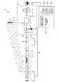
図1で示すように、トンネル切羽前方探査システムSは、トンネルTの切羽近傍に配置される受振器Aと、トンネルTの切羽前方を掘削する削孔装置Mと、削孔装置Mに設置され、パイロットセンサ10を備える振動センサ機構1と、受振器A及びパイロットセンサ10で受振したビット振動に係る情報を処理するデータ処理装置4と、を備えている。≪Tunnel face forward exploration system≫
As shown in FIG. 1, the tunnel face front exploration system S includes a geophone A arranged near the face of the tunnel T, a drilling device M for excavating the front face of the tunnel T, and a drilling device M. , a
削孔装置Mは、いわゆる先端打撃方式の削孔装置であり、削孔機2と、削孔機2の後端部に振動センサ機構1を介して接続される掘削ロッド3と、掘削ロッド3を把持して回転力と推進力を付与するボーリングマシンBとを備えている。 The drilling device M is a so-called tip impact type drilling device, and includes a
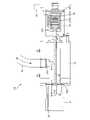
削孔機2は、地山を削孔する掘削ビット21と、掘削ビット21の背面側に位置して打撃を発生させる振動発生機構22とを備える。本実施の形態では、振動発生機構22に水圧ハンマーを採用しており、図1及び図2で示すように、前端部が掘削ビット21の背面側に接続され、後端部に高圧水Wが流入する開口を有する筒体221と、筒体221内で、筒体221内の中間部を塞ぐように配置される逆止弁と、逆止弁の挙動に連動して筒体221の前端側もしくは後端側に移動するピストンと、を備えている(逆止弁及びピストンは図示していない)。 The
筒体221の開口より高圧水Wが流入すると、筒体221内における高圧水Wの流れ方向が前端部方向となって逆止弁が開状態になるとともに、ピストンは筒体221の前端部方向に移動し、その先端が掘削ビット21の背面を打撃して移動が停止する。すると、ピストンと逆止弁の間における高圧水Wの流れ方向が後端側方向となって逆止弁が閉状態になるとともに、ピストンは筒体221の後端部方向に移動して、その先端が掘削ビット21の背面から離間する。 When the high-pressure water W flows in from the opening of the
筒体221に高圧水Wが供給されている間中、上記の動作が繰り返されることにより、振動発生機構22は掘削ビット21に連続的な打撃を発生させて地山を削孔する。このようにして、掘削ビット21によりトンネルTの切羽前方地山を削孔することにより、掘削ビット21から発生するビット振動は、図1で示すように、受振器Aおよび振動センサ機構1に備えたパイロットセンサ10により連続的に受振される。また、これら2地点で受振されたビット振動情報は、トンネルTの坑内もしくは工事事務所等に設置されるデータ処理装置4に伝送される。 While the high-pressure water W is being supplied to the
受振器Aは、弾性波探査で一般に採用される3成分加速度計であって、トンネルTの坑内から地山に向けて削孔される計測孔Hに設置され、地山を伝わるビット振動情報を受振する。振動センサ機構1に備えるパイロットセンサ10は、掘削ビット21から削孔機2を伝わるビット振動を受振するセンサであり、受振器Aと同様に弾性波探査で一般に採用される3成分加速度計を採用できるが、本実施の形態では、パイロットセンサ10に求められる精度や配置スペース等を考慮し、1成分加速度計を採用している。 The geophone A is a three-component accelerometer commonly used in seismic exploration, and is installed in a measurement hole H that is drilled from the inside of the tunnel T toward the ground. Receive vibrations. The
データ処理装置4は、データ収録システム41と、データ解析装置42とを備え、データ収録システム41は、いわゆるデータロガーであり、受振器A及びパイロットセンサ10が受振したビット振動情報を読み取り、データ解析装置42に出力する。 The data processing device 4 includes a
データ解析装置42は、演算処理装置421、入力部422、出力部423及び記憶部424等を備えた、いわゆるノート型パソコンやタブレット端末であり、入力部422は、データ収録システム41で読み取ったビット振動情報を入力する入力機能と、スイッチ、キーボード等の入力装置を備える。 The data analysis device 42 is a so-called notebook computer or tablet terminal equipped with an
また、出力部423は、画面表示を行うディスプレイやプリンタ等の出力装置を備え、記憶部424は、半導体メモリ又はハードディスクドライブ等からなる記憶装置であり、演算処理装置421によって実行可能なプログラムが格納されている。 In addition, the
演算処理装置421は、CPU、GPU、ROM、RAM及びハードウェアインタフェース等を有するコンピュータであり、受振器A及びパイロットセンサ10で受振したビット振動情報に基づいて、地山の弾性波速度を算出する弾性波速度算出部4211を少なくとも備えている。なお、トンネル切羽前方探査システムSで地山状況を把握できる範囲は、トンネルTの切羽位置と掘削ビット21の配置位置の間の領域内に限定される。 The
上述する構成のトンネル切羽前方探査システムSは、振動センサ機構1を削孔機2に備えた振動発生機構22の背面側に配置することで、最も掘削ビット21に近接した位置にパイロットセンサ10を配置する。これにより、地山削孔時に掘削ビット21から発生するビット振動を、実振動に近い状態で受振できる。 The tunnel face forward exploration system S configured as described above arranges the
また、掘削ビット21に打撃を発生させる振動発生機構22を掘削ビット21の背面側に配置した削孔機2を用いて、先端打撃方式の先進ボーリングを行うことで、従来より実施されている掘削ロッド3の後端部近傍にドリフタ等の打撃装置を配置し、掘削ロッド3を介して掘削ビット21に打撃を発生させる後端打撃方式と比較して、削孔長を長大化できる。これにより1回の削孔探査で、トンネルTの切羽前方の地山状況を広範囲にわたって把握できる。 In addition, by using the
さらに、削孔長が長大化し、掘削ロッド3に多数のジョイント部が設けられることに伴い、ジョイント部で掘削ロッド3を伝達するビット振動が重複反射を生じる場合にも、パイロットセンサ10が掘削ロッド3の先端部に配置されるため、これら重複反射に起因するノイズの影響を受けることなく、ビット振動を受振できる。 Furthermore, as the drilling length increases and the
また、削孔機2は、ドリフタ等の打撃装置と異なり、地山の削孔中に打撃装置に起因する大きな機械振動を発生しないため、パイロットセンサ10は、掘削ビット21から発生するビット振動を、最もノイズの少ない環境下で受振できる。 In addition, unlike an impact device such as a drifter, the
≪掘削ロッド及び振動センサ機構≫
ところで、本実施の形態では、削孔機2の振動発生機構22に水圧ハンマーを採用していることから、掘削ロッド3及び振動センサ機構1に、振動発生機構22へ作動流体である高圧水Wを供給する機能を持たせている。また、パイロットセンサ10を備える振動センサ機構1が掘削ロッド3の先端部に設置されることから、掘削ロッド3及び振動センサ機構1を、パイロットセンサ10で受振したビット振動情報をデータ処理装置4に伝送するための二芯の電気ケーブルとして機能させている。≪Drilling rod and vibration sensor mechanism≫
By the way, in the present embodiment, since a hydraulic hammer is adopted as the
そこで、本実施の形態における掘削ロッド3と、パイロットセンサ10を備える振動センサ機構1の構造について、以下に説明する。 Therefore, the structure of the
<掘削ロッド>
掘削ロッド3は、図1で示すように、金属製の中空筒体よりなる掘削ロッド本体5と、導電材料で形成された高導電性金属棒であり、掘削ロッド本体5より十分小さい断面径を有する導電棒7と、掘削ロッド本体5と導電棒7との間に介装されるスペーサ9と、を備えている。<Drilling rod>
As shown in FIG. 1, the
スペーサ9は、図3で示すように、導電棒7を把持する把持部91と、把持部91の外縁より突出し、突出端部が掘削ロッド本体5の内周面に当接する導電棒支持部92と、を有する。また、スペーサ9は、導電棒7を把持した状態で掘削ロッド本体5へ挿入した際に、掘削ロッド本体5の中空部を閉塞することのないよう、切欠きや通し孔等により形成された連通部93を備えている。 As shown in FIG. 3, the
これら、把持部91、導電棒支持部92及び連通部93は、いずれの形状を有するものでもよいが、本実施の形態では、把持部91が導電棒7を包持するようリング形状に形成され、導電棒支持部92は把持部91の外縁より放射方向に3体突出し、隣り合う導電棒支持部92の間に連通部93が設けられている。 The
掘削ロッド3は、このような構成のスペーサ9を長手方向に間隔を設けて複数取り付けた導電棒7を掘削ロッド本体5に挿入することにより、導電棒7と掘削ロッド本体5との間に確保した隙間を、高圧水Wが流下する作動流体流路L1として機能させている。なお、スペーサ9には連通部93が設けられているため、高圧水Wは連通部93を通過でき、掘削ロッド3内をスムーズに流下することが可能となっている。 The
また、掘削ロッド3は、金属製の掘削ロッド本体5をマイナス配線と見做すとともに、導電棒7をプラス配線と見做して2芯の電気ケーブルとして機能させることができる。 Further, the
ところで、掘削ロッド3は、地山削孔が進行するにつれてその長さを伸長させるものである。このため、図2で示すように、複数の掘削ロッド一般部3aにより構成されるとともに、掘削ロッド一般部3aは長手方向に継ぎ足し自在な構成を有している。 By the way, the
掘削ロッド一般部3aは、掘削ロッド本体5の分割体の一部である掘削ロッド本体一般部5aと、導電棒7の分割体の一部である導電棒一般部7aと、掘削ロッド本体一般部5aと導電棒一般部7aとの間に介装されるスペーサ9と、を備えている。 The drilling rod
掘削ロッド本体一般部5aは、一方の端部にメス継手61が設けられるとともに、このメス継手61に嵌合するオス継手62が他方の端部に設けられている。また、掘削ロッド本体一般部5aに収納される導電棒一般部7aは、一方の端部にオス電極部81が設けられるとともに、このオス電極部81に嵌合するメス電極部82が他方の端部に形成されている。 The drilling rod main body
掘削ロッド本体一般部5aにおける導電棒一般部7aのオス電極部81とメス電極部82の配置位置は、隣り合う掘削ロッド一般部3aどうしを接続する際、一方の掘削ロッド本体一般部5aのオス継手62を他方の掘削ロッド本体一般部5aのメス継手61に嵌合させることにより、隣り合う導電棒一般部7aのオス電極部81とメス電極部82が、自動的に差し込まれる位置に配置されている。 The arrangement positions of the
また、スペーサ9は、図3で示した把持部91、導電棒支持部92、連通部93に加えてさらに、導電棒支持部92の各々に押圧部94を設置してもよい。図2で示すように、板バネよりなる押圧部94はその基端部が、導電棒支持部92の導電棒一般部7aの軸線と直交する面に固定され、導電棒一般部7aと離間する方向に向けて延在し、導電棒支持部92の突出端部より導電棒一般部7aの軸線直交方向に張り出したところで、先端部が内巻きに加工処理されている。 Further, the
押圧部94をスペーサ9に備えると、3体の導電棒支持部92各々に設けられた3体の押圧部94が、掘削ロッド本体一般部5aの内周面を押圧することから、着脱自在でありながら導電棒一般部7aを掘削ロッド本体一般部5aに対して強固に固定することができる。 When the
<振動センサ機構>
このような掘削ロッド3の先端部に設置される振動センサ機構1は、図2及び図4で示すように、パイロットセンサ10と、パイロットセンサ10が固定される固定台11と、固定台11に固定された状態のパイロットセンサ10が挿入されるセンサケース12と、センサケース12に一端が接続されるセンサ側導電棒13と、センサ側導電棒13およびセンサケース12が挿入されるケースロッド14とを備える。<Vibration sensor mechanism>
As shown in FIGS. 2 and 4, the
ケースロッド14は、金属製の中空筒体よりなり、図2で示すように、一方の端部に振動発生機構22の後端部に位置する筒体221が挿入され、ケースロッド14の一方の端部がメス継手61、振動発生機構22の筒体221がオス継手62の態様で接続されている。また、他方の端部は、掘削ロッド3の掘削ロッド本体5に接続されている。 The
なお、掘削ロッド本体5の一方の端部にメス継手61が、ケースロッド14の他方の端部にメス継手61と嵌合するオス継手62が、それぞれ形成されている。また、これら振動発生機構22の筒体221及び掘削ロッド本体5はともに、ケースロッド14に対して中空部が連通する状態で着脱自在に接続されている。 A female joint 61 is formed at one end of the excavating
センサ側導電棒13は、掘削ロッド3の導電棒7と同様の導電材料で形成された高導電性金属棒よりなり、長手方向をケースロッド14の軸線と平行にして、ケースロッド14の中空部に配置されている。また、導電棒7と同様にスペーサ9が設置されており、このスペーサ9によりセンサ側導電棒13とケースロッド14との間の隙間は、安定した状態で確保されている。そして、センサ側導電棒13の一端はセンサケース12に接続され、他端はメス電極部82が備えられており、掘削ロッド3の導電棒7に備えたオス電極部81に接続する。 The sensor-side
センサケース12は、図2及び図4(a)で示すように、ケースロッド14の内周面に外接する大きさの外形形状を有する中空筒体よりなり、一方の端部にケース蓋121が着脱自在に嵌合される開口が形成され、他方の端部はセンサ側導電棒13の一端と接続する接続端子122が配置された状態で閉塞されている。なお、ケース蓋121にはOリング等の止水材が設置されており、センサケース12の中空部は水密状態に保持されるが、必要に応じてグリースGを充填してもよい。 As shown in FIGS. 2 and 4A, the
また、図4で示すように、センサケース12の外周面には、ケースロッド14に挿入された際に、ケースロッド14の軸線方向に延在する切欠き部123が複数形成されており、センサケース12の外周面とケースロッド14の間に隙間が形成されている。この隙間は、図2で示すように、スペーサ9の連通部93により形成されたケースロッド14とセンサ側導電棒13の隙間と連通し、振動発生機構22に供給する高圧水Wが流下する作動流体流路L2として機能する。 Further, as shown in FIG. 4, a plurality of
固定台11は、図2及び図4(b)で示すように、パイロットセンサ10が設置される長尺の固定板111を備え、長手方向がセンサケース12の軸線方向と平行となるようにして、センサケース12の開口からその中空部に、パイロットセンサ10を設置した状態で挿入される。 As shown in FIGS. 2 and 4B, the fixed
固定台11はその大きさが、図2で示すように、センサケース12の開口をケース蓋121で塞いだ際に、センサケース13の中空部でガタツキが生じない大きさに形成されている。 As shown in FIG. 2, the fixed
また、固定台11には、センサ側導電棒13と対向する側の端部に、パイロットセンサ10から延びるプラス配線と接続されるとともに、センサケース12に設けた接続端子122に備えたメスコネクタ(図示せず)に接続するオスコネクタ112が設置されている。なお、パイロットセンサ10から延びるマイナス配線は、固定台11に接続されている。 In addition, the fixed
上記の振動センサ機構1は、固定台11、センサケース12及びケースロッド14がいずれも金属製の部材により製作されており、これらをマイナス配線と見做し、センサ側導電棒13をプラス配線と見做し、2芯の電気ケーブルとして機能させることができる。 In the
≪ロータリージョイント付き高圧スイベル≫
一方、掘削ロッド3の後端部は、図1及び図2で示すように、ボーリングマシンBに備えたロータリージョイント付き高圧スイベル15を介してデータ収録装置4及び高圧水供給パイプPに連結されている。以下に、掘削ロッド3をデータ処理装置4のデータ収録システム41および高圧水供給パイプPと接続するために用いるロータリージョイント付き高圧スイベル15について、詳細を説明する。≪High pressure swivel with rotary joint≫
On the other hand, as shown in FIGS. 1 and 2, the rear end of the
図5で示すように、ロータリージョイント付き高圧スイベル15は、中空筒状に形成されたハウジング16と、ハウジング16を挟んで一方側に設置される中空状の回転シャフト17と、他方側に設置される回転コネクタ収納部18と、回転コネクタ収納部18、ハウジング16及び回転シャフト17の3者に跨って延在する延長導電棒19と、を備える。 As shown in FIG. 5, the rotary joint-equipped high-
ハウジング16は、内空部へ高圧水Wを注入させるためのポート161が側周面に形成されており、このポート161に高圧水供給パイプPが接続される。また、ハウジング16の一方の端部には高圧水Wの供給口162が形成されており、回転シャフト17が中空部を供給口162と連通するようにして設置されている。 The
回転シャフト17は、一方の端部に掘削ロッド3の掘削ロッド本体5と接続可能なメス継手61を有し、他方の端部が、軸線がハウジング16の軸線と合致するように配置され、軸線周りに回転可能に設置されている。 The rotating
これにより、図2で示すように、振動センサ機構1のケースロッド14と掘削ロッド3の掘削ロッド本体5とを接続し、回転シャフト17に掘削ロッド3を接続させたうえで、高圧水供給パイプPをハウジング16に接続し高圧水Wを注入すると、ハウジング16の供給口162から回転シャフト17を介して掘削ロッド3及び振動センサ機構1に高圧水Wが流入する。 As a result, as shown in FIG. 2, the
したがって、高圧水供給パイプPからハウジング16及び回転シャフト17を介して掘削ロッド3に流入した高圧水Wは、掘削ロッド3に形成された作動流体流路L1および振動センサ機構1に形成された作動流体流路L2を介して振動発生機構22の筒体221に供給され、振動発生機構22に採用した水圧ハンマーを作動させることが可能となる。 Therefore, the high-pressure water W flowing into the
また、延長導電棒19は、掘削ロッド3の導電棒7と同様の導電材料で形成された高導電性金属棒よりなり、ハウジング16及び回転シャフト17の軸線上に延在する。その一端は、回転シャフト17の中空部に位置し、回転シャフト17に接続される掘削ロッド3に備えた導電棒7のメス電極部82と接続可能な、オス電極部81が設置されている。また、他端は、ハウジング16を貫通して回転コネクタ収納部18に挿入されている。 The extension
回転コネクタ収納部18は、回転体に外部から電力・電気信号を伝達することができる回転コネクタ181を収納した筒体であり、この回転コネクタ181に延長導電棒19の他端が接続されるとともに、データ処理装置4のデータ収録システム41が接続される。 The rotating
なお、本実施の形態では回転コネクタ181として、回転体1811に配置された金属製リング1812とブラシ1813を介して電力や信号を伝達するスリップリングを採用し、なかでも、延長導電棒19を回転体1811の回転軸に取り付ける軸端取り付けタイプのスリップリングを採用している。 In this embodiment, as the
したがって、振動センサ機構1のケースロッド14と掘削ロッド3の掘削ロッド本体5を接続するとともに、掘削ロッド3の掘削ロッド本体5を回転シャフト17に接続する。また、振動センサ機構1のセンサ側導電棒13に備えたメス電極部82と掘削ロッド3の導電棒7に備えたオス電極部81とを接続するとともに、導電棒7に備えたメス電極部82を延長導電棒19に備えたオス電極部81に接続し、さらに、データ収録システム41を回転コネクタ181に接続する。 Therefore, the
すると、図1で示すように、データ収録システム41から、2芯の電気ケーブルとしての機能を有する掘削ロッド3及び振動センサ機構1を経由して、パイロットセンサ10に電力が供給されるとともに、パイロットセンサ10からデータ収録システム41にビット振動情報が伝送される。 Then, as shown in FIG. 1, power is supplied from the
このように、電気ケーブルを追加配置することなく掘削ロッド3及び振動センサ機構1を利用して、パイロットセンサ10で受振したビット振動に係る情報の伝送や、パイロットセンサ10への給電を行うことが可能となる。また、排水管を追加配置することなく、掘削ロッド3を利用して高圧水Wを供給することができ、削孔装置の構造を簡略化することができる。 In this way, it is possible to transmit information related to the bit vibration received by the
なお、上記のとおり、ロータリージョイント付き高圧スイベル15のハウジング16内、掘削ロッド3に形成された作動流体流路L1および振動センサ機構1に形成された作動流体流路L2には、高圧水Wが流下する。このため、ロータリージョイント付き高圧スイベル15の延長導電棒19、掘削ロッド3の導電棒7及び振動センサ機構1のセンサ側導電棒13はそれぞれ、図2及び図5で示すように、高圧水が直接触れることのないよう電気絶縁材料よりなる絶縁部材Eにより被覆され、漏電対策が講じられている。 As described above, in the
また、導電棒7を構成する導電棒一般部7a及びセンサ側導電棒13に備えたメス電極部82は、その外周部が絶縁部材(図示せず)により形成されており、オス電極部81が差し込まれると絶縁が確保されるキャップ状に形成されている。また、内周面には止水ゴムとして一般に広く用いられているOリング(図示せず)が設置されており、オス電極部81が嵌合して形成される接続部は、水密構造となっている。さらに、掘削ロッド3及び振動センサ機構1の両者に用いられているスペーサ9も、電気絶縁材料により形成されている。 In addition, the conductive rod
≪トンネル切羽前方地山の探査方法≫
上記のトンネル切羽前方探査システムを用いたトンネル切羽前方地山の探査方法を、以下に説明する。なお、トンネル切羽前方地山の探査方法は、トンネルの掘削作業が所定距離だけ進んだところで、一旦掘削作業を停止したうえで実施する。≪Exploration method for the ground in front of the tunnel face≫
A method of searching for the ground in front of the tunnel face using the tunnel face front survey system described above will be described below. In addition, the exploration method for the ground in front of the tunnel face is carried out after the tunnel excavation work is temporarily stopped when the tunnel excavation work has progressed by a predetermined distance.
まず、図1で示すように、トンネルTの坑内から地山に向けてトンネル軸線と交差する方向に計測孔Hを削孔し、受振器Aを設置する。併せて、削孔機2と掘削ロッド3の間にパイロットセンサ10を備える振動センサ機構1を接続した削孔装置Mを、トンネルTの切羽近傍における所定位置に据え付けるとともに、受振器A及び掘削装置Mをデータ処理装置4に接続する。 First, as shown in FIG. 1, a measurement hole H is drilled from the pit of the tunnel T toward the natural ground in a direction intersecting the tunnel axis, and a geophone A is installed. At the same time, a drilling device M having a
次に、削孔装置Mを用いてトンネルTから切羽前方地山の削孔作業を開始する。削孔作業と併せて、地山を掘削する掘削ビット21から発生するビット振動を、受振器A及びパイロットセンサ10の各々で連続的に受振する。 Next, the drilling operation of the ground ahead of the face is started from the tunnel T using the drilling device M. Along with the drilling work, the geophone A and the
具体的には、トンネルTの切羽近傍に位置する計測孔Hに設置された受振器Aでは、振動源である掘削ビット21の位置から地山を伝わって到達したビット振動を受振する。一方、掘削ロッド3の先端部に設置され、削孔機2の後端部近傍に近接して位置するパイロットセンサ10では、掘削ビット21から削孔機2を伝わるビット振動を受振する。 Specifically, the geophone A installed in the measurement hole H located near the face of the tunnel T receives the bit vibration that reaches from the position of the
これら受振器A及びパイロットセンサ10で受振したビット振動情報は、データ処理装置4のデータ収録システム41で読み取るとともにデータ解析装置42に出力する。データ解析装置42では、演算処理装置421の弾性波速度算出部4211において、掘削ビット21の位置からトンネル切羽の範囲におけるトンネル前方地山の弾性波速度を算定する。 The bit vibration information received by the geophone A and the
上記の作業は、掘削ビット21が所望の地点に到達するまで、掘削ロッド3の長さを掘削ロッド一般部3aを継ぎ足しつつ調整しながら実施する。なお、掘削ロッド一般部3aのロッド長さ3m程度、削孔距離は最長で約150m程度である。 The above work is carried out while adjusting the length of the
≪弾性波速度の算出方法≫
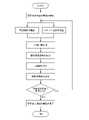
次に、トンネル切羽前方地山の探査方法により取得したビット振動情報に基づいて、トンネル切羽前方地山の弾性波速度を算出する方法の概要を、図6のフロー図に沿って説明する。≪How to calculate elastic wave velocity≫
Next, an outline of a method for calculating the seismic velocity of the ground ahead of the tunnel face based on the bit vibration information acquired by the exploration method of the ground ahead of the tunnel face will be described with reference to the flowchart of FIG.
まず、受振器Aで受振した地山を伝わって到達したビット振動情報から観測波形を抽出するとともに、パイロットセンサ10で受振したビット振動情報からパイロット波形を抽出する。 First, an observed waveform is extracted from the bit vibration information received by the geophone A and arriving through the ground, and a pilot waveform is extracted from the bit vibration information received by the
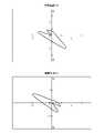
次に、図7で示すように、観測波形について、振動方向の異なる弾性波形記録(鉛直方向U-D、互いに直交する水平方向2成分(R、L))のパーティクルオービットを作成したうえで、パーティクルオービットに基づく解析方法により、波動到来方向(受振器Aから見て掘削ビット21が位置する方向)の振動成分を抽出する。 Next, as shown in FIG. 7, for the observed waveform, after creating a particle orbit of elastic waveform records with different vibration directions (vertical direction UD, two horizontal components (R, L) orthogonal to each other), An analysis method based on particle orbiting is used to extract the vibration component in the wave arrival direction (the direction in which the
この後、観測波形の波動到来方向の振動成分とパイロット波形とを、時間同期したうえで相互相関処理を行い、受振器A及びパイロットセンサ10間の疑似受振波形を算定する。 After that, the oscillation component of the wave arrival direction of the observed waveform and the pilot waveform are time-synchronized and subjected to cross-correlation processing to calculate the pseudo-received waveform between the geophone A and the
これら疑似受振波形に基づいて、図8で示すように、受振器A~パイロットセンサ10間の伝搬時間Trを算定するとともに、掘削ビット21から発生したビット振動がパイロットセンサ10に到達するまでの時間T1を算定して両者を足し合わせることにより、掘削ビット21のビット振動が受振器Aに到達する到達時間T2を算定する。 Based on these pseudo vibration waveforms, as shown in FIG. By calculating T1 and adding both, the arrival time T2 for the bit vibration of the excavating
こうして得られた到達時間T2を利用して、従来より実施されているダウンホール方式の速度検層に倣って、切羽前方地山の弾性波速度を算定する。ダウンホールタイプの速度検層は、地表に発振源を設定するとともにボーリング孔に受振点を設定し、地盤深度ごとでP波の初動時間を算定する。そして、地盤深度と初動時間の関係から走時曲線を作成する方法である。 Using the arrival time T2 obtained in this way, the seismic velocity of the ground ahead of the face is calculated in accordance with the conventional downhole velocity logging. In the downhole type velocity logging, the oscillation source is set on the ground surface and the receiving point is set in the borehole, and the initial motion time of the P wave is calculated for each ground depth. Then, it is a method of creating a travel-time curve from the relationship between the ground depth and the initial movement time.
このように、ダウンホールタイプの速度検層では、発振源を地上に配置するとともに受振点をボーリング孔内に設定して初動時間を算定している一方で、トンネル切羽前方探査方法では、発振源である掘削ビット21が削孔内に位置しているとともに、受振点である受振器AがトンネルTの切羽近傍に配置された状態で到達時間を算定しており、両者では発振源の位置と受振点の位置が逆転した関係にある。 In this way, in the downhole type velocity logging, the oscillation source is placed on the ground and the receiving point is set in the borehole to calculate the initial motion time. The arrival time is calculated with the
しかし、弾性波の伝搬に関して相反定理が成り立つことが知られている。つまり、発信源と受振点の間に位置する地山の走時曲線を、発振源と受振点の位置関係を入れ替えて算定しても、その算定結果は相似関係にあるというものである。したがって、トンネル切羽前方探査方法では、この相反定理に従って、トンネル切羽前方の地山における弾性波速度を算定するものである。 However, it is known that the reciprocity theorem holds for elastic wave propagation. In other words, even if the traveltime curve of the ground located between the source and the receiving point is calculated by exchanging the positional relationship between the source and the receiving point, the calculation results are similar. Therefore, in the tunnel face forward exploration method, the elastic wave velocity in the ground ahead of the tunnel face is calculated according to this reciprocity theorem.
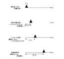
具体的には、切羽前方地山の削孔作業を進めながら、前述したように受振器A及びパイロットセンサ10の両者でビット振動情報を連続的に受振して、切羽からの削孔距離ごとに到達時間T2を算定する。そして、図9で示すように、縦軸に削孔距離を取るとともに横軸に到達時間を取ったグラフに、削孔距離と到達時間T2の関係をプロットし、走時曲線を作成する。この走時曲線から傾きが変化する地点を速度境界層と判定したうえで、各地点間ごとの走時曲線勾配から弾性波速度を算定する。 Specifically, while the drilling work of the ground in front of the face is progressing, as described above, the bit vibration information is continuously received by both the geophone A and the
図9のグラフをみると、トンネル切羽から150m前方まで掘進する間に傾きが変化する速度境界層が5地点で存在し、これらの地点間毎に弾性波速度(Vp1~Vp6が算定されている様子が見て取れる。Looking at the graph in Fig. 9, there are five velocity boundary layers whose slopes change while excavating from the tunnel face to 150 m ahead, and elastic wave velocities (Vp1 to Vp6 ) are calculated between these points. You can see how it is.
上記のとおり、トンネル切羽前方探査システムSを用いたトンネル切羽前方の探査方法によれば、パイロットセンサ10は、実振動に近い状態のビット振動を最もノイズの少ない環境下で受振できる。したがって、受振したビット振動情報を用いて算出する弾性波速度の精度を向上することが可能になるとともに、弾性波速度から推定する地山に関する構成や硬軟、含水の程度等の地山状況に高い信頼性を確保することが可能となる。 As described above, according to the tunnel face front exploration method using the tunnel face front exploration system S, the
また、パイロットセンサ10で受振してビット振動情報に対するノイズの除去作業を省略できるため、解析システムの簡略化を図ることができるとともに、算定の迅速化及びデータ容量のスリム化を図ることが可能となる。 In addition, since the
本発明のトンネル切羽前方探査システム及びトンネル切羽前方の探査方法は、上記実施形態に限定されるものではなく、本発明の趣旨を逸脱しない範囲で種々の変更が可能である。 The tunnel face front exploration system and the tunnel face front exploration method of the present invention are not limited to the above-described embodiments, and various modifications are possible without departing from the scope of the present invention.
例えば、本実施の形態では、掘削ビットに打撃を発生させる振動発生機構として水圧ハンマーを採用したが、他の流体を用いた打撃ハンマを採用する等、掘削ビットに打撃力を付与可能な機構であれば、いずれのものを採用してもよい。 For example, in the present embodiment, a hydraulic hammer is used as the vibration generating mechanism for generating impact on the drilling bit, but a mechanism capable of imparting impact force to the drilling bit, such as a impact hammer using another fluid, may be used. Either one may be used, if any.
1 振動センサ機構
2 削孔機
21 掘削ビット
22 振動発生機構
221 筒体
3 掘削ロッド
4 データ処理装置
41 データ収録システム
42 データ解析装置
421 演算処理装置
4211 弾性波速度算出部
422 入力部
423 出力部
424 記憶部
5 掘削ロッド本体
5a 掘削ロッド本体一般部
61 メス継手
62 オス継手
63 受け口
7 導電棒
7a 導電棒一般部
81 オス電極部
82 メス電極部
9 スペーサ
91 把持部
92 導電棒支持部
93 連通部
94 押圧部
10 パイロットセンサ
11 固定台
12 センサケース
121 ケース蓋
122 接続端子
123 切欠き部
13 センサ側導電棒
14 ケースロッド
15 ロータリージョイント付き高圧スイベル
16 ハウジング
17 回転シャフト
18 回転コネクタ収納部
181 回転コネクタ
1811 回転体
1812 金属製リング
1813 ブラシ
19 延長導電棒
A 受振器
B ボーリングマシン
L1 作動流体流路
L2 作動流体流路
M 削孔装置
S トンネル切羽前方探査システム
W 高圧水(作動流体)
P 高圧水供給パイプ
G グリース
E 絶縁部材1
A Geophone B Boring machine L1 Working fluid flow path L2 Working fluid flow path M Drilling device S Tunnel face forward exploration system W High-pressure water (working fluid)
P High-pressure water supply pipe G Grease E Insulating member
Claims (3)
Translated fromJapanese前記掘削ビットに打撃を発生させる振動発生機構が、前記掘削ビットの背面側に配置されるとともに、
該振動発生機構の背面側に、前記パイロットセンサおよび該パイロットセンサを収納するセンサケースを備えた振動センサ機構が配置され、
該振動センサ機構が、掘削ロッドの先端部に設置されることを特徴とするトンネル切羽前方探査システムWhile drilling the front face of a tunnel with a drill bit, the bit vibration generated from the drill bit is continuously received at two points, a geophone installed near the face and a pilot sensor placed near the drill bit. A tunnel face forward exploration system that calculates the elastic wave velocity in front of the face based on the information of the two points obtained,
A vibration generating mechanism for generating an impact on the drilling bit is arranged on the back side of the drilling bit, and
A vibration sensor mechanism including the pilot sensor and a sensor case for housing the pilot sensor is arranged on the back side of the vibration generating mechanism,
A tunnel face forward exploration system characterized in that the vibration sensor mechanism is installed at the tip of an excavation rod.
前記掘削ロッドが、金属製の中空筒体よりなる掘削ロッド本体と、該掘削ロッド本体の中空部に挿入される導電棒とを備えるとともに、
前記振動センサ機構が、前記センサケースに設置した接続端子に一方の端部が接続されるセンサ側導電棒と、該センサ側導電棒及び前記センサケースが挿入される金属製のケースロッドと、を備え、
該ケースロッドが、前記掘削ロッド本体及び前記振動発生機構の両者に、中空部を連通させた状態で接続され、
前記センサケースが金属製であり、その外周面の少なくとも一部が前記ケースロッドの内周面に接触され、
前記センサ側導電棒の他方の端部が、前記掘削ロッドの前記導電棒と接続されることを特徴とするトンネル切羽前方探査システム。In the tunnel face forward exploration system according to claim 1,
The drilling rod includes a drilling rod body made of a metal hollow cylinder, and a conductive rod inserted into the hollow part of the drilling rod body,
The vibration sensor mechanism includes a sensor-side conductive rod having one end connected to a connection terminal installed in the sensor case, and a metal case rod into which the sensor-side conductive rod and the sensor case are inserted. prepared,
The case rod is connected to both the drilling rod body and the vibration generating mechanism in a state in which the hollow portion is in communication,
The sensor case is made of metal, and at least part of its outer peripheral surface is in contact with the inner peripheral surface of the case rod,
A tunnel face forward exploration system, wherein the other end of the sensor-side conductive rod is connected to the conductive rod of the excavation rod.
トンネルの坑内から切羽前方の地山を前記掘削ビットにより削孔しつつ、前記掘削ビットから発生するビット振動を、切羽近傍に設置した前記受振器及び前記振動センサ機構に備えた前記パイロットセンサの2地点で連続的に受振し、
受振した2地点のビット振動情報に基づいて、切羽前方の弾性波速度を算出することを特徴とするトンネル切羽前方地山の探査方法。A tunnel face exploration method using the tunnel face exploration system according to claim 1 or 2,
2 of the geophone installed in the vicinity of the face and the pilot sensor provided in the vibration sensor mechanism for detecting bit vibration generated from the excavation bit while drilling the ground ahead of the face from the inside of the tunnel with the said excavation bit. received continuously at a point,
A method of searching for ground in front of a tunnel face, comprising calculating elastic wave velocities in front of the face based on bit vibration information received at two points.
Priority Applications (1)
| Application Number | Priority Date | Filing Date | Title |
|---|---|---|---|
| JP2019042521AJP7200013B2 (en) | 2019-03-08 | 2019-03-08 | Tunnel Face Forward Exploration System and Tunnel Face Forward Exploration Method |
Applications Claiming Priority (1)
| Application Number | Priority Date | Filing Date | Title |
|---|---|---|---|
| JP2019042521AJP7200013B2 (en) | 2019-03-08 | 2019-03-08 | Tunnel Face Forward Exploration System and Tunnel Face Forward Exploration Method |
Publications (2)
| Publication Number | Publication Date |
|---|---|
| JP2020144067A JP2020144067A (en) | 2020-09-10 |
| JP7200013B2true JP7200013B2 (en) | 2023-01-06 |
Family
ID=72355558
Family Applications (1)
| Application Number | Title | Priority Date | Filing Date |
|---|---|---|---|
| JP2019042521AActiveJP7200013B2 (en) | 2019-03-08 | 2019-03-08 | Tunnel Face Forward Exploration System and Tunnel Face Forward Exploration Method |
Country Status (1)
| Country | Link |
|---|---|
| JP (1) | JP7200013B2 (en) |
Families Citing this family (3)
| Publication number | Priority date | Publication date | Assignee | Title |
|---|---|---|---|---|
| JP7404147B2 (en)* | 2020-04-28 | 2023-12-25 | 株式会社大林組 | Swivel joint and tunnel face forward exploration system |
| CN115469354A (en)* | 2022-08-04 | 2022-12-13 | 山东大学 | Data acquisition method based on high-frequency elastic wave forecasting technology standardization |
| JP7742817B2 (en)* | 2022-08-17 | 2025-09-22 | 公益財団法人鉄道総合技術研究所 | Ground movement prediction method and ground movement prediction system |
Citations (6)
| Publication number | Priority date | Publication date | Assignee | Title |
|---|---|---|---|---|
| JP2000506235A (en) | 1996-02-26 | 2000-05-23 | アバディーン ユニヴァーシティ | Tunnel excavator and ground sensing system |
| JP2000170478A (en) | 1998-12-07 | 2000-06-20 | Taisei Corp | Exploration method in front of tunnel face |
| JP2003066155A (en) | 2001-08-30 | 2003-03-05 | Mitsui Constr Co Ltd | Method and apparatus for detecting ground and mountain states |
| JP2016017900A (en) | 2014-07-10 | 2016-02-01 | 大成建設株式会社 | Tunnel face forward exploration method |
| JP2017066646A (en) | 2015-09-29 | 2017-04-06 | 鹿島建設株式会社 | Groundwater measurement method and drilling rod in ground drilling |
| JP2017128881A (en) | 2016-01-19 | 2017-07-27 | 鹿島建設株式会社 | Ground-water pressure measuring method in ground drilling and drill rod |
Family Cites Families (1)
| Publication number | Priority date | Publication date | Assignee | Title |
|---|---|---|---|---|
| JPS57146895A (en)* | 1981-03-09 | 1982-09-10 | Hitachi Construction Machinery | Vibration type pipe embedding apparatus |
- 2019
- 2019-03-08JPJP2019042521Apatent/JP7200013B2/enactiveActive
Patent Citations (6)
| Publication number | Priority date | Publication date | Assignee | Title |
|---|---|---|---|---|
| JP2000506235A (en) | 1996-02-26 | 2000-05-23 | アバディーン ユニヴァーシティ | Tunnel excavator and ground sensing system |
| JP2000170478A (en) | 1998-12-07 | 2000-06-20 | Taisei Corp | Exploration method in front of tunnel face |
| JP2003066155A (en) | 2001-08-30 | 2003-03-05 | Mitsui Constr Co Ltd | Method and apparatus for detecting ground and mountain states |
| JP2016017900A (en) | 2014-07-10 | 2016-02-01 | 大成建設株式会社 | Tunnel face forward exploration method |
| JP2017066646A (en) | 2015-09-29 | 2017-04-06 | 鹿島建設株式会社 | Groundwater measurement method and drilling rod in ground drilling |
| JP2017128881A (en) | 2016-01-19 | 2017-07-27 | 鹿島建設株式会社 | Ground-water pressure measuring method in ground drilling and drill rod |
Also Published As
| Publication number | Publication date |
|---|---|
| JP2020144067A (en) | 2020-09-10 |
Similar Documents
| Publication | Publication Date | Title |
|---|---|---|
| JP7200013B2 (en) | Tunnel Face Forward Exploration System and Tunnel Face Forward Exploration Method | |
| EP3109400B1 (en) | Drill sensor system and method | |
| CN104181581B (en) | Earthquake wave underground construction space observation system and method based on random arrangement | |
| NO342382B1 (en) | Method for logging soil formations during drilling of a wellbore | |
| US20100155137A1 (en) | Segmented Tubular Body | |
| US20160291186A1 (en) | Seismic cable, system and method for acquiring information about seismic, microseismic and mechanical vibration incidents in a well | |
| JP4260329B2 (en) | Geological exploration method in front of tunnel face | |
| JP4157635B2 (en) | Tunnel face forward exploration method | |
| CN105301645B (en) | A kind of shield construction method for forecasting advanced geology and system | |
| JP6646983B2 (en) | Method for exploring the front of the face | |
| US12360275B2 (en) | Method for monitoring hydraulic fracturing range of surface vertical shaft | |
| JP7237664B2 (en) | drilling rod | |
| JPH10153666A (en) | Prediction method for geology of crust in face front in tunnel | |
| JP5258734B2 (en) | Tunnel front face exploration method and exploration system | |
| CN101460868A (en) | Method and apparatus for determining formation resistivity ahead of the bit and azimuthal at the bit | |
| JP7237663B2 (en) | Vibration sensor mechanism | |
| JP5285290B2 (en) | Excavator and forward exploration method of face | |
| CN109738964B (en) | Tunnel prediction device, tunneling machine and method for seismic wave and electromagnetic wave joint inversion | |
| JP6396824B2 (en) | Shield tunnel forward exploration device and method | |
| JP7404147B2 (en) | Swivel joint and tunnel face forward exploration system | |
| CN119738867B (en) | Passive tunnel boring poor geological detection device and method | |
| JP2018063124A (en) | Geological survey device and geological survey method | |
| JP6688605B2 (en) | Front face exploration method | |
| KR101596313B1 (en) | geophysical logging probe with propulsion for inserting in the incline borehole | |
| CN120315023A (en) | A microseismic monitoring method for fracture-type rockburst in deep and long-distance TBM tunnels |
Legal Events
| Date | Code | Title | Description |
|---|---|---|---|
| A621 | Written request for application examination | Free format text:JAPANESE INTERMEDIATE CODE: A621 Effective date:20220217 | |
| TRDD | Decision of grant or rejection written | ||
| A977 | Report on retrieval | Free format text:JAPANESE INTERMEDIATE CODE: A971007 Effective date:20221118 | |
| A01 | Written decision to grant a patent or to grant a registration (utility model) | Free format text:JAPANESE INTERMEDIATE CODE: A01 Effective date:20221122 | |
| A61 | First payment of annual fees (during grant procedure) | Free format text:JAPANESE INTERMEDIATE CODE: A61 Effective date:20221221 | |
| R150 | Certificate of patent or registration of utility model | Ref document number:7200013 Country of ref document:JP Free format text:JAPANESE INTERMEDIATE CODE: R150 |