JP7199415B2 - Intraluminal imager using multiple center frequencies - Google Patents
Intraluminal imager using multiple center frequenciesDownload PDFInfo
- Publication number
- JP7199415B2 JP7199415B2JP2020504021AJP2020504021AJP7199415B2JP 7199415 B2JP7199415 B2JP 7199415B2JP 2020504021 AJP2020504021 AJP 2020504021AJP 2020504021 AJP2020504021 AJP 2020504021AJP 7199415 B2JP7199415 B2JP 7199415B2
- Authority
- JP
- Japan
- Prior art keywords
- ultrasound
- transducer
- ivus
- ultrasonic
- center frequency
- Prior art date
- Legal status (The legal status is an assumption and is not a legal conclusion. Google has not performed a legal analysis and makes no representation as to the accuracy of the status listed.)
- Active
Links
Images


Classifications
- A—HUMAN NECESSITIES
- A61—MEDICAL OR VETERINARY SCIENCE; HYGIENE
- A61B—DIAGNOSIS; SURGERY; IDENTIFICATION
- A61B8/00—Diagnosis using ultrasonic, sonic or infrasonic waves
- A61B8/44—Constructional features of the ultrasonic, sonic or infrasonic diagnostic device
- A61B8/4483—Constructional features of the ultrasonic, sonic or infrasonic diagnostic device characterised by features of the ultrasound transducer
- A61B8/4494—Constructional features of the ultrasonic, sonic or infrasonic diagnostic device characterised by features of the ultrasound transducer characterised by the arrangement of the transducer elements
- A—HUMAN NECESSITIES
- A61—MEDICAL OR VETERINARY SCIENCE; HYGIENE
- A61B—DIAGNOSIS; SURGERY; IDENTIFICATION
- A61B8/00—Diagnosis using ultrasonic, sonic or infrasonic waves
- A61B8/44—Constructional features of the ultrasonic, sonic or infrasonic diagnostic device
- A61B8/4444—Constructional features of the ultrasonic, sonic or infrasonic diagnostic device related to the probe
- A61B8/4461—Features of the scanning mechanism, e.g. for moving the transducer within the housing of the probe
- A—HUMAN NECESSITIES
- A61—MEDICAL OR VETERINARY SCIENCE; HYGIENE
- A61B—DIAGNOSIS; SURGERY; IDENTIFICATION
- A61B8/00—Diagnosis using ultrasonic, sonic or infrasonic waves
- A61B8/06—Measuring blood flow
- A—HUMAN NECESSITIES
- A61—MEDICAL OR VETERINARY SCIENCE; HYGIENE
- A61B—DIAGNOSIS; SURGERY; IDENTIFICATION
- A61B8/00—Diagnosis using ultrasonic, sonic or infrasonic waves
- A61B8/08—Clinical applications
- A61B8/0833—Clinical applications involving detecting or locating foreign bodies or organic structures
- A61B8/085—Clinical applications involving detecting or locating foreign bodies or organic structures for locating body or organic structures, e.g. tumours, calculi, blood vessels, nodules
- A—HUMAN NECESSITIES
- A61—MEDICAL OR VETERINARY SCIENCE; HYGIENE
- A61B—DIAGNOSIS; SURGERY; IDENTIFICATION
- A61B8/00—Diagnosis using ultrasonic, sonic or infrasonic waves
- A61B8/08—Clinical applications
- A61B8/0891—Clinical applications for diagnosis of blood vessels
- A—HUMAN NECESSITIES
- A61—MEDICAL OR VETERINARY SCIENCE; HYGIENE
- A61B—DIAGNOSIS; SURGERY; IDENTIFICATION
- A61B8/00—Diagnosis using ultrasonic, sonic or infrasonic waves
- A61B8/12—Diagnosis using ultrasonic, sonic or infrasonic waves in body cavities or body tracts, e.g. by using catheters
- A—HUMAN NECESSITIES
- A61—MEDICAL OR VETERINARY SCIENCE; HYGIENE
- A61B—DIAGNOSIS; SURGERY; IDENTIFICATION
- A61B8/00—Diagnosis using ultrasonic, sonic or infrasonic waves
- A61B8/44—Constructional features of the ultrasonic, sonic or infrasonic diagnostic device
- A61B8/4444—Constructional features of the ultrasonic, sonic or infrasonic diagnostic device related to the probe
- A61B8/445—Details of catheter construction
- A—HUMAN NECESSITIES
- A61—MEDICAL OR VETERINARY SCIENCE; HYGIENE
- A61B—DIAGNOSIS; SURGERY; IDENTIFICATION
- A61B8/00—Diagnosis using ultrasonic, sonic or infrasonic waves
- A61B8/44—Constructional features of the ultrasonic, sonic or infrasonic diagnostic device
- A61B8/4477—Constructional features of the ultrasonic, sonic or infrasonic diagnostic device using several separate ultrasound transducers or probes
- A—HUMAN NECESSITIES
- A61—MEDICAL OR VETERINARY SCIENCE; HYGIENE
- A61B—DIAGNOSIS; SURGERY; IDENTIFICATION
- A61B8/00—Diagnosis using ultrasonic, sonic or infrasonic waves
- A61B8/48—Diagnostic techniques
- A61B8/488—Diagnostic techniques involving Doppler signals
- A—HUMAN NECESSITIES
- A61—MEDICAL OR VETERINARY SCIENCE; HYGIENE
- A61B—DIAGNOSIS; SURGERY; IDENTIFICATION
- A61B8/00—Diagnosis using ultrasonic, sonic or infrasonic waves
- A61B8/52—Devices using data or image processing specially adapted for diagnosis using ultrasonic, sonic or infrasonic waves
- A61B8/5215—Devices using data or image processing specially adapted for diagnosis using ultrasonic, sonic or infrasonic waves involving processing of medical diagnostic data
- A61B8/5238—Devices using data or image processing specially adapted for diagnosis using ultrasonic, sonic or infrasonic waves involving processing of medical diagnostic data for combining image data of patient, e.g. merging several images from different acquisition modes into one image
- A61B8/5246—Devices using data or image processing specially adapted for diagnosis using ultrasonic, sonic or infrasonic waves involving processing of medical diagnostic data for combining image data of patient, e.g. merging several images from different acquisition modes into one image combining images from the same or different imaging techniques, e.g. color Doppler and B-mode
- A—HUMAN NECESSITIES
- A61—MEDICAL OR VETERINARY SCIENCE; HYGIENE
- A61B—DIAGNOSIS; SURGERY; IDENTIFICATION
- A61B5/00—Measuring for diagnostic purposes; Identification of persons
- A61B5/0059—Measuring for diagnostic purposes; Identification of persons using light, e.g. diagnosis by transillumination, diascopy, fluorescence
- A61B5/0082—Measuring for diagnostic purposes; Identification of persons using light, e.g. diagnosis by transillumination, diascopy, fluorescence adapted for particular medical purposes
- A61B5/0084—Measuring for diagnostic purposes; Identification of persons using light, e.g. diagnosis by transillumination, diascopy, fluorescence adapted for particular medical purposes for introduction into the body, e.g. by catheters
- A—HUMAN NECESSITIES
- A61—MEDICAL OR VETERINARY SCIENCE; HYGIENE
- A61B—DIAGNOSIS; SURGERY; IDENTIFICATION
- A61B6/00—Apparatus or devices for radiation diagnosis; Apparatus or devices for radiation diagnosis combined with radiation therapy equipment
- A61B6/12—Arrangements for detecting or locating foreign bodies
- A—HUMAN NECESSITIES
- A61—MEDICAL OR VETERINARY SCIENCE; HYGIENE
- A61B—DIAGNOSIS; SURGERY; IDENTIFICATION
- A61B6/00—Apparatus or devices for radiation diagnosis; Apparatus or devices for radiation diagnosis combined with radiation therapy equipment
- A61B6/52—Devices using data or image processing specially adapted for radiation diagnosis
- A61B6/5211—Devices using data or image processing specially adapted for radiation diagnosis involving processing of medical diagnostic data
- A61B6/5229—Devices using data or image processing specially adapted for radiation diagnosis involving processing of medical diagnostic data combining image data of a patient, e.g. combining a functional image with an anatomical image
- A61B6/5247—Devices using data or image processing specially adapted for radiation diagnosis involving processing of medical diagnostic data combining image data of a patient, e.g. combining a functional image with an anatomical image combining images from an ionising-radiation diagnostic technique and a non-ionising radiation diagnostic technique, e.g. X-ray and ultrasound
- A—HUMAN NECESSITIES
- A61—MEDICAL OR VETERINARY SCIENCE; HYGIENE
- A61B—DIAGNOSIS; SURGERY; IDENTIFICATION
- A61B8/00—Diagnosis using ultrasonic, sonic or infrasonic waves
- A61B8/42—Details of probe positioning or probe attachment to the patient
- A61B8/4272—Details of probe positioning or probe attachment to the patient involving the acoustic interface between the transducer and the tissue
- A61B8/4281—Details of probe positioning or probe attachment to the patient involving the acoustic interface between the transducer and the tissue characterised by sound-transmitting media or devices for coupling the transducer to the tissue
- A—HUMAN NECESSITIES
- A61—MEDICAL OR VETERINARY SCIENCE; HYGIENE
- A61B—DIAGNOSIS; SURGERY; IDENTIFICATION
- A61B8/00—Diagnosis using ultrasonic, sonic or infrasonic waves
- A61B8/52—Devices using data or image processing specially adapted for diagnosis using ultrasonic, sonic or infrasonic waves
- A61B8/5215—Devices using data or image processing specially adapted for diagnosis using ultrasonic, sonic or infrasonic waves involving processing of medical diagnostic data
- A61B8/5238—Devices using data or image processing specially adapted for diagnosis using ultrasonic, sonic or infrasonic waves involving processing of medical diagnostic data for combining image data of patient, e.g. merging several images from different acquisition modes into one image
- G—PHYSICS
- G06—COMPUTING OR CALCULATING; COUNTING
- G06T—IMAGE DATA PROCESSING OR GENERATION, IN GENERAL
- G06T2207/00—Indexing scheme for image analysis or image enhancement
- G06T2207/10—Image acquisition modality
- G06T2207/10132—Ultrasound image
- G—PHYSICS
- G06—COMPUTING OR CALCULATING; COUNTING
- G06T—IMAGE DATA PROCESSING OR GENERATION, IN GENERAL
- G06T2207/00—Indexing scheme for image analysis or image enhancement
- G06T2207/30—Subject of image; Context of image processing
- G06T2207/30004—Biomedical image processing
- G06T2207/30101—Blood vessel; Artery; Vein; Vascular
Landscapes
- Health & Medical Sciences (AREA)
- Life Sciences & Earth Sciences (AREA)
- Engineering & Computer Science (AREA)
- Medical Informatics (AREA)
- Surgery (AREA)
- Pathology (AREA)
- Radiology & Medical Imaging (AREA)
- Biophysics (AREA)
- Biomedical Technology (AREA)
- Heart & Thoracic Surgery (AREA)
- Physics & Mathematics (AREA)
- Molecular Biology (AREA)
- Nuclear Medicine, Radiotherapy & Molecular Imaging (AREA)
- Animal Behavior & Ethology (AREA)
- General Health & Medical Sciences (AREA)
- Public Health (AREA)
- Veterinary Medicine (AREA)
- Vascular Medicine (AREA)
- Gynecology & Obstetrics (AREA)
- Hematology (AREA)
- Computer Vision & Pattern Recognition (AREA)
- Ultra Sonic Daignosis Equipment (AREA)
Description
Translated fromJapanese本開示は、広くは、血管内超音波(IVUS)撮像に関し、特に、血管内撮像装置の撮像素子に関する。例えば、前記撮像素子は、異なる中心周波数で動作する複数の超音波トランスデューサを含むことができる。 TECHNICAL FIELD This disclosure relates generally to intravascular ultrasound (IVUS) imaging, and more particularly to imaging elements for intravascular imaging devices. For example, the imaging device can include multiple ultrasound transducers operating at different center frequencies.
血管内超音波(IVUS)撮像は、インターベンション心臓学において、治療の必要性を決定する、インターベンションをガイドする、及び/又はその有効性を評価するために人体内の動脈のような病変血管を評価する診断ツールとして幅広く使用されている。1以上の超音波トランスデューサを含むIVUS装置は、血管内に通され、撮像されるべき領域までガイドされる。トランスデューサは、関心血管の画像を作成するために超音波エネルギを放射する。超音波は、(血管壁の様々な層のような)組織構造、赤血球、及び他の関心フィーチャから生じる不連続性により部分的に反射される。反射波からのエコーは、前記トランスデューサにより受信され、IVUS撮像システムに伝えられる。前記撮像システムは、受信された超音波エコーを処理して、装置が配置される血管の断面画像を生成する。 Intravascular ultrasound (IVUS) imaging is used in interventional cardiology to examine diseased vessels, such as arteries, within the human body to determine the need for therapy, guide interventions, and/or assess their effectiveness. It is widely used as a diagnostic tool to evaluate An IVUS device, including one or more ultrasound transducers, is passed intravascularly and guided to the area to be imaged. A transducer emits ultrasound energy to create an image of the vessel of interest. Ultrasound is partially reflected by discontinuities arising from tissue structures (such as the various layers of the vessel wall), red blood cells, and other features of interest. Echoes from the reflected waves are received by the transducer and transmitted to the IVUS imaging system. The imaging system processes the received ultrasound echoes to produce cross-sectional images of the vessel in which the device is located.
(合成開口としても知られる)ソリッドステートIVUSカテーテル及び回転式IVUSカテーテルは、今日一般的に使用されている2つのタイプのIVUS装置である。両方のタイプのIVUS装置が、血管系の周辺の周りで撮像することができる。回転式IVUS装置に対して、可撓性細長部材の遠位部分に配置された側方視トランスデューサは、可撓性細長部材の長手軸の周りを回転しながら血管系をスキャンする。ソリッドステートIVUSカテーテルは、トランスデューサアレイに隣接して取り付けられた1以上の集積回路コントローラチップと一緒に周辺の周りに分散された超音波トランスデューサのアレイを含むスキャナアセンブリを持っている。コントローラは、超音波パルスを送信し、超音波エコー信号を受信する個別のトランスデューサ素子(又は素子のグループ)を選択する。送信‐受信対のシーケンスを通ることにより、ソリッドステートIVUSシステムは、部品を移動することなしに(よってソリッドステート指定)、機械的にスキャンされた超音波トランスデューサの効果を合成することができる。 Solid-state IVUS catheters (also known as synthetic apertures) and rotational IVUS catheters are two types of IVUS devices in common use today. Both types of IVUS devices can image around the perimeter of the vascular system. For rotational IVUS devices, a side-viewing transducer positioned at the distal portion of the flexible elongate member rotates about the longitudinal axis of the flexible elongate member while scanning the vasculature. A solid-state IVUS catheter has a scanner assembly that includes an array of ultrasound transducers distributed around the periphery with one or more integrated circuit controller chips mounted adjacent to the transducer array. A controller selects individual transducer elements (or groups of elements) to transmit ultrasonic pulses and receive ultrasonic echo signals. By going through a sequence of transmit-receive pairs, a solid-state IVUS system can synthesize the effect of a mechanically scanned ultrasound transducer without moving parts (hence the solid-state designation).
従来、IVUS装置は、回転式かソリッドステートかにかかわらず、単一の中心周波数で動作する超音波トランスデューサ又は超音波トランスデューサのアレイを備える。より高い中心周波数で動作する超音波トランスデューサは、より低い中心周波数で動作する超音波トランスデューサより高い空間解像度を持つが、より低い浸透深さを持つので、中心周波数で動作する超音波トランスデューサ又は複数の超音波トランスデューサを持つことに関連して浸透深さと空間解像度との間のトレードオフが常に存在する。IVUS撮像が進化するにつれて、表示における解像度を改善するようにより高い超音波周波数に向けた一定の移行が存在している。しかしながら、超音波周波数が増加されると、血液エコーと血管壁組織エコーとの間のコントラストが減少される。IVUSの初期世代に使用された20MHz中心周波数において、血液エコーは、音響波長と比較した赤血球細胞の小さなサイズのため血管壁エコーと比較して非常に弱い。しかしながら、IVUS撮像に対して現在一般的に使用される40MHzの超音波中心周波数において、この高い周波数における超音波波長が、赤血球細胞の寸法に近いので、血液エコーと組織エコーとの間には若干の差しか存在しない。血液エコーと組織エコーとの間の更に大きな差を達成するためには、更に高い中心周波数が必要でありうる。しかしながら、高い中心周波数で動作するこのようなIVUS装置は、浸透深さが犠牲になるので血管壁組織を撮像するのに十分ではないかもしれない。 Conventionally, IVUS devices, whether rotary or solid state, include an ultrasound transducer or array of ultrasound transducers operating at a single center frequency. Ultrasonic transducers operating at higher center frequencies have higher spatial resolution, but lower penetration depths, than ultrasonic transducers operating at lower center frequencies. There is always a trade-off between penetration depth and spatial resolution associated with having an ultrasound transducer. As IVUS imaging evolves, there is a constant shift towards higher ultrasound frequencies to improve resolution in display. However, as the ultrasound frequency is increased, the contrast between blood echoes and vessel wall tissue echoes is reduced. At the 20 MHz center frequency used in early generations of IVUS, blood echoes are very weak compared to vessel wall echoes due to the small size of red blood cells compared to the acoustic wavelength. However, at the 40 MHz ultrasound center frequency currently commonly used for IVUS imaging, the ultrasound wavelength at this high frequency is close to the size of red blood cells, so there is a slight difference between blood and tissue echoes. There is only a difference between Higher center frequencies may be required to achieve greater differences between blood and tissue echoes. However, such IVUS devices operating at high center frequencies may not be adequate for imaging vessel wall tissue as penetration depth is sacrificed.
従来のソリッドステートIVUS装置は、血流の方向が、主にIVUS撮像面に垂直であるので、ドップラカラーフロー撮像には受け入れられない。より具体的には、ドップラカラーフロー撮像及び他のドップラ技術は、関心速度(すなわち、血流速度)が、撮像面に垂直であり、超音波伝搬の方向に垂直であり、結果としてゼロに近い血流に起因するドップラシフトを生じる場合に良好には機能しない。 Conventional solid-state IVUS devices are unacceptable for Doppler color flow imaging because the direction of blood flow is primarily perpendicular to the IVUS imaging plane. More specifically, Doppler color flow imaging and other Doppler techniques assume that the velocity of interest (i.e., blood flow velocity) is perpendicular to the imaging plane and perpendicular to the direction of ultrasound propagation, resulting in near zero. It does not work well when producing Doppler shifts due to blood flow.
したがって、既存の血管内超音波撮像装置が、概して一般的な目的に対して受け入れられるのに対し、これらは、全ての側面において満足のいくものではない。様々な目的で異なる中心周波数で動作する超音波トランスデューサを含む医療撮像装置に対する要望が存在する。 Thus, while existing intravascular ultrasound imaging devices are generally acceptable for general purposes, they are not satisfactory in all respects. A need exists for a medical imaging device that includes ultrasound transducers that operate at different center frequencies for various purposes.
本開示の実施例は、異なる中心周波数で動作するトランスデューサを使用して血管の画像を生成する改善された血管内超音波撮像装置を提供する。前記血管内撮像装置の可撓性細長部材の遠位部分は、撮像アセンブリを含むことができる。前記撮像アセンブリは、第1の中心周波数で動作する第1の超音波トランスデューサ及び前記第1の中心周波数とは異なる第2の中心周波数で動作する第2の超音波トランスデューサを含むことができる。いくつかの実施例において、前記撮像アセンブリは、第1の中心周波数で動作する複数の第1の超音波トランスデューサ及び第2の中心周波数で動作する複数の第2の超音波トランスデューサを持つことができる。前記複数の第1の超音波トランスデューサは、前記可撓性細長部材の長手軸の周りに環状に配置された又は前記可撓性細長部材の長手軸に平行に線形に配置されたトランスデューサアレイのいずれかを形成することができる。 Embodiments of the present disclosure provide an improved intravascular ultrasound imaging system that uses transducers operating at different center frequencies to generate images of blood vessels. A distal portion of the flexible elongate member of the intravascular imaging device can include an imaging assembly. The imaging assembly can include a first ultrasonic transducer operating at a first center frequency and a second ultrasonic transducer operating at a second center frequency different from the first center frequency. In some embodiments, the imaging assembly can have a plurality of first ultrasonic transducers operating at a first center frequency and a plurality of second ultrasonic transducers operating at a second center frequency. . The plurality of first ultrasonic transducers is either a transducer array arranged annularly about the longitudinal axis of the flexible elongate member or linearly arranged parallel to the longitudinal axis of the flexible elongate member. can form
一実施例において、血管内超音波(IVUS)撮像装置が、提供される。前記IVUS撮像装置は、患者の内腔内に配置されるように構成され、近位部分及び遠位部分を有する可撓性細長部材と、前記可撓性細長部材の前記遠位部分に配置された撮像アセンブリとを含む。前記撮像アセンブリは、第1の中心周波数で動作する第1の超音波トランスデューサ及び前記第1の中心周波数とは異なる第2の中心周波数で動作する第2の超音波トランスデューサを含む。 In one embodiment, an intravascular ultrasound (IVUS) imaging device is provided. The IVUS imaging device is configured to be disposed within a lumen of a patient and includes a flexible elongate member having a proximal portion and a distal portion, and a flexible elongate member disposed on the distal portion of the flexible elongate member. and an imaging assembly. The imaging assembly includes a first ultrasonic transducer operating at a first center frequency and a second ultrasonic transducer operating at a second center frequency different from the first center frequency.
いくつかの実施例において、前記IVUS撮像装置の前記第1の超音波トランスデューサは、複数の第1の超音波トランスデューサの中の1つであり、前記IVUS撮像装置の前記第2の超音波トランスデューサは、複数の第2の超音波トランスデューサの中の1つである。いくつかの実施例において、前記複数の第1の超音波トランスデューサは、前記可撓性細長部材の長手軸の周りに環状に配置された第1のトランスデューサアレイを形成し、前記複数の第2の超音波トランスデューサは、前記可撓性細長部材の長手軸の周りに環状に配置された第2のトランスデューサアレイを形成する。前記第1のトランスデューサアレイは、前記第2のトランスデューサアレイの近位に配置される。いくつかの実施例において、前記複数の第1の超音波トランスデューサは、前記可撓性細長部材の長手軸の周りに環状に配置された第1のトランスデューサアレイを形成し、前記複数の第2の超音波トランスデューサは、前記可撓性細長部材の長手軸に平行に線形に配置される。これらの実施例において、前記第2の中心周波数は、前記第1の中心周波数より高い。いくつかの実施例において、前記複数の第1の超音波トランスデューサは、前記可撓性細長部材の長手軸の周りに環状に配置されたトランスデューサアレイを形成し、前記複数の第2の超音波トランスデューサの各々は、前記複数の第1の超音波トランスデューサの中の2つの間に置かれる。 In some embodiments, the first ultrasound transducer of the IVUS imaging device is one of a plurality of first ultrasound transducers, and the second ultrasound transducer of the IVUS imaging device is , one of the plurality of second ultrasonic transducers. In some embodiments, the plurality of first ultrasonic transducers form a first transducer array arranged annularly about the longitudinal axis of the flexible elongate member, and the plurality of second ultrasonic transducers The ultrasonic transducers form a second transducer array arranged annularly around the longitudinal axis of the flexible elongate member. The first transducer array is positioned proximal to the second transducer array. In some embodiments, the plurality of first ultrasonic transducers form a first transducer array arranged annularly about the longitudinal axis of the flexible elongate member, and the plurality of second ultrasonic transducers An ultrasonic transducer is arranged linearly parallel to the longitudinal axis of the flexible elongate member. In these embodiments, the second center frequency is higher than the first center frequency. In some embodiments, the plurality of first ultrasonic transducers form a transducer array arranged annularly about the longitudinal axis of the flexible elongate member, and the plurality of second ultrasonic transducers is positioned between two of the plurality of first ultrasonic transducers.
いくつかの他の実施例において、前記IVUS撮像装置の前記撮像アセンブリは、前記細長部材の長手軸の周りを回転するように構成される。これらの実施例において、前記第1の超音波トランスデューサは、前記第2の超音波トランスデューサの遠位に隣接して配置される。更に、これらの実施例において、前記IVUS撮像装置は、前記第1及び第2の中心周波数とは異なる第3の中心周波数で動作する第3の超音波トランスデューサを更に含み、前記第3の超音波トランスデューサは、前記第2の超音波トランスデューサの近位に隣接して配置される。いくつかの実施例において、前記第3の超音波トランスデューサは、第1の角度で遠位に傾斜する。いくつかの例において、前記第1の超音波トランスデューサは、第2の角度で近位に傾斜する。 In some other embodiments, the imaging assembly of the IVUS imaging device is configured to rotate about the longitudinal axis of the elongate member. In these embodiments, the first ultrasonic transducer is positioned distally adjacent to the second ultrasonic transducer. Additionally, in these embodiments, the IVUS imaging device further comprises a third ultrasound transducer operating at a third center frequency different from the first and second center frequencies, wherein the third ultrasound A transducer is positioned proximally adjacent to the second ultrasound transducer. In some embodiments, the third ultrasound transducer is distally angled at a first angle. In some examples, the first ultrasound transducer is proximally tilted at a second angle.
一実施例において、IVUS撮像システムが、提供される。前記IVUS撮像システムは、患者の内腔内に配置されるように構成され、近位部分及び遠位部分を有する可撓性細長部材と、前記可撓性細長部材の前記遠位部分に配置された撮像アセンブリと、制御及び処置装置とを含む。前記撮像アセンブリは、第1の中心周波数で動作する第1の複数の超音波トランスデューサと、第1の中心周波数とは異なる第2の中心周波数で動作する第2の複数の超音波トランスデューサとを含む。前記制御及び処理装置は、前記第1の複数の超音波トランスデューサ及び前記第2の複数の超音波トランスデューサと通信する。前記制御及び処理装置は、前記内腔の第1の超音波データを取得するように前記第1の複数の超音波トランスデューサにエネルギ供給し、前記第1の超音波データに基づいてグレイスケール超音波画像を生成し、前記内腔を流れる流体の第2の超音波データを取得ように前記第2の複数の超音波トランスデューサにエネルギ供給し、前記第2の超音波データに基づいてカラードップラ超音波画像を生成し、前記グレイスケール超音波画像及びカラードップラ超音波画像をディスプレイに出力するように動作可能である。 In one embodiment, an IVUS imaging system is provided. The IVUS imaging system is configured to be placed within a lumen of a patient and includes a flexible elongate member having a proximal portion and a distal portion, and a flexible elongate member disposed on the distal portion of the flexible elongate member. an imaging assembly, and a control and treatment device. The imaging assembly includes a first plurality of ultrasonic transducers operating at a first center frequency and a second plurality of ultrasonic transducers operating at a second center frequency different from the first center frequency. . The control and processing unit communicates with the first plurality of ultrasonic transducers and the second plurality of ultrasonic transducers. The control and processing unit energizes the first plurality of ultrasound transducers to acquire first ultrasound data of the lumen, and performs grayscale ultrasound based on the first ultrasound data. generating an image, energizing the second plurality of ultrasound transducers to acquire second ultrasound data of fluid flowing through the lumen, and performing color Doppler ultrasound based on the second ultrasound data; It is operable to generate an image and output the grayscale ultrasound image and the color Doppler ultrasound image to a display.
いくつかの実施例において、前記撮像アセンブリの前記第1の複数の超音波トランスデューサは、前記可撓性細長部材の長手軸の周りに環状に配置された第1のトランスデューサアレイを形成する。いくつかの実施例において、前記撮像アセンブリの前記第2の複数の超音波トランスデューサは、前記可撓性細長部材の長手軸に平行に線形に配置される。これらの実施例において、前記第2の中心周波数は、前記第1の中心周波数より高い。いくつかの実施例において、前記IVUS撮像システムの前記制御及び処理装置は、前記グレイスケール超音波画像上にカラードップラ超音波画像を重ね合わせ、前記グレイスケール超音波画像上に重ね合わされた前記カラードップラ超音波画像を前記ディスプレイに出力するように動作可能である。いくつかの実施例において、前記IVUS撮像システムの前記制御及び処理装置は、前記可撓性細長部材の長手軸に沿って順次的に前記第2の複数の超音波トランスデューサにエネルギ供給するように動作可能である。 In some embodiments, the first plurality of ultrasound transducers of the imaging assembly form a first transducer array arranged annularly about the longitudinal axis of the flexible elongate member. In some embodiments, the second plurality of ultrasound transducers of the imaging assembly are arranged linearly parallel to the longitudinal axis of the flexible elongate member. In these embodiments, the second center frequency is higher than the first center frequency. In some embodiments, the control and processing unit of the IVUS imaging system superimposes a color Doppler ultrasound image on the grayscale ultrasound image; It is operable to output ultrasound images to the display. In some embodiments, the control and processing unit of the IVUS imaging system operates to sequentially energize the second plurality of ultrasound transducers along the longitudinal axis of the flexible elongate member. It is possible.
他の実施例において、IVUS撮像システムが、提供される。前記IVUS撮像システムは、患者の内腔内に配置されるように構成され、近位部分及び遠位部分を有する可撓性細長部材と、前記可撓性細長部材の前記遠位部分に配置され、前記可撓性細長部材の長手軸の周りを回転するように構成される撮像アセンブリと、制御及び処理装置とを含む。前記撮像アセンブリは、第1の中心周波数で動作する第1の超音波トランスデューサと、前記第1の中心周波数とは異なる第2の中心周波数で動作する第2の超音波トランスデューサとを含む。前記制御及び処理装置は、前記第1の超音波トランスデューサ及び前記第2の超音波トランスデューサと通信し、前記内腔の第1の超音波データを取得するように前記第1の超音波トランスデューサにエネルギ供給し、前記第1の超音波データに基づいてグレイスケール超音波画像を生成し、前記内腔を流れる流体の第2の超音波データを取得するように前記第2の超音波トランスデューサにエネルギ供給し、前記第2の超音波データに基づいてカラードップラ超音波画像を生成し、前記グレイスケール超音波画像及びカラードップラ超音波画像をディスプレイに出力するように動作可能である。いくつかの実施例において、前記撮像アセンブリの前記第2の超音波トランスデューサは、ある角度で近位に傾斜され、前記第2の中心周波数は、前記第1の中心周波数より高い。いくつかの実施例において、前記撮像アセンブリは、前記第1及び第2の中心周波数とは異なる第3の中心周波数で動作する第3の超音波トランスデューサを更に含む。 In another embodiment, an IVUS imaging system is provided. The IVUS imaging system is configured to be placed within a lumen of a patient and includes a flexible elongate member having a proximal portion and a distal portion, and a flexible elongate member disposed on the distal portion of the flexible elongate member. , an imaging assembly configured to rotate about the longitudinal axis of the flexible elongate member, and a control and processing unit. The imaging assembly includes a first ultrasonic transducer operating at a first center frequency and a second ultrasonic transducer operating at a second center frequency different from the first center frequency. The control and processing unit communicates with the first ultrasonic transducer and the second ultrasonic transducer and energizes the first ultrasonic transducer to acquire first ultrasonic data of the lumen. and energizing the second ultrasonic transducer to generate a grayscale ultrasonic image based on the first ultrasonic data and acquire second ultrasonic data of fluid flowing through the lumen. and generating a color Doppler ultrasound image based on the second ultrasound data, and outputting the grayscale ultrasound image and the color Doppler ultrasound image to a display. In some embodiments, the second ultrasound transducer of the imaging assembly is proximally tilted at an angle and the second center frequency is higher than the first center frequency. In some embodiments, the imaging assembly further includes a third ultrasonic transducer operating at a third center frequency different from the first and second center frequencies.
本開示の追加の態様、フィーチャ及び利点は、以下の詳細な記載から明らかになる。 Additional aspects, features, and advantages of the present disclosure will become apparent from the detailed description that follows.
本開示の例示的実施例は、添付の図面を参照して記載される。 Exemplary embodiments of the present disclosure are described with reference to the accompanying drawings.
本開示の原理の理解を促進する目的で、ここで、図面に示された実施例が参照され、特定の言語が、同じものを記載するのに使用される。それにもかかわらず、本開示の範囲に対する限定が意図されないと理解される。記載される装置、システム及び方法に対する任意の変更及び更なる修正、並びに本開示の原理の任意の更なる応用は、本開示が関連する当業者が通常に気が付くので、完全に予期され、本開示内に含まれる。例えば、焦点システムが、心臓血管撮像に関して記載されるが、この応用に限定されることが意図されないと理解される。前記システムは、狭い空洞内で撮像することを要求する任意の応用に等しく良好に適している。特に、1つの実施例に関して記載されたフィーチャ、コンポーネント及び/又はステップが、本開示の他の実施例に関して記載されたフィーチャ、コンポーネント及び/又はステップと組み合わせられてもよいことは、完全に予期される。簡潔さのため、しかしながら、これらの組み合わせの多くの反復は、別々に記載されない。 For the purposes of promoting an understanding of the principles of the disclosure, reference will now be made to the embodiments illustrated in the drawings, and specific language will be used to describe the same. It will nevertheless be understood that no limitation on the scope of the disclosure is intended. Any changes and further modifications to the described apparatus, systems and methods, as well as any further applications of the principles of the present disclosure, are fully anticipated and fully anticipated by those skilled in the art to which this disclosure pertains. contained within. For example, while the focus system is described with respect to cardiovascular imaging, it is understood that it is not intended to be limited to this application. The system is equally well suited for any application requiring imaging within a narrow cavity. In particular, it is fully anticipated that features, components and/or steps described with respect to one embodiment may be combined with features, components and/or steps described with respect to other embodiments of the disclosure. be. For brevity, however, many iterations of these combinations are not listed separately.
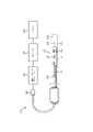
図1は、本開示の態様による、ソリッドステートIVUS撮像システム100の概略図である。IVUS撮像システム100は、カテーテル、ガイドワイヤ又はガイドカテーテルのようなソリッドステートIVUS装置102(時々、可撓性細長部材と称される)と、患者インタフェースモジュール(PIM)104と、IVUS処理システム又はコンソール(時々、制御及び処理装置と称される)106と、ディスプレイ108とを含みうる。 FIG. 1 is a schematic diagram of a solid-state
ハイレベルにおいて、ソリッドステートIVUS装置102は、前記カテーテル装置の遠位端の近くに取り付けられたトランスデューサアセンブリ110に含まれるトランスデューサ素子124から超音波エネルギを放射する。前記超音波エネルギは、トランスデューサアセンブリ110を囲む、血管120のような、媒体内の組織構造により反射され、超音波エコー信号が、トランスデューサ素子124により受信される。トランスデューサ素子124は、コントローラ126により制御されることができる。PIM104は、(流れ情報を含む)超音波画像が再構成され、ディスプレイ108上に表示されるコンソール又はコンピュータ106に前記受信されたエコー信号を転送する。コンソール又はコンピュータ106は、プロセッサ及びメモリを含むことができる。コンピュータ又は計算装置106は、ここに記載されたIVUS撮像システム100のフィーチャを容易にするように動作可能であることができる。例えば、前記プロセッサは、非一時的有形コンピュータ可読媒体に記憶されたコンピュータ可読命令を実行することができる。 At a high level, solid-
PIM104は、IVUSコンソール106とソリッドステートIVUS装置102に含まれるトランスデューサアセンブリ110との間の信号の通信を容易化する。いくつかの実施例において、PIM104は、データをコンソール106に中継する前に前記エコーデータの予備処理を実行する。このような実施例の例において、PIM104は、前記データの増幅、フィルタ処理及び/又は統合を実行する。一実施例において、PIM104は、トランスデューサアセンブリ110内の回路を含む装置102の動作をサポートするように高及び低電圧DCパワーを供給する。
IVUSコンソール106は、PIM104を経由してトランスデューサアセンブリ110から前記エコーデータを受信し、トランスデューサアセンブリ110を囲む前記媒体内の組織構造の画像を再構成するように前記データを処理する。コンソール106は、血管120の断面画像のような、血管120の画像が、ディスプレイ108上に表示されるように、画像データを出力する。血管120は、自然及び人工の両方の流体充填構造又は囲まれた構造を表しうる。血管120は、内腔1200を規定する。血管120は、患者の体内でありうる。血管120は、心臓血管系、末梢血管系、神経血管系、腎血管系及び/又は体内の他の適切な内腔を含む、患者の血管系の動脈又は静脈のような血管でありうる。例えば、装置102は、腔内撮像装置であってもよい。例えば、装置102は、限定なしで、肝臓、心臓、腎臓、胆嚢、膵臓、肺、導管、腸を含む器官、脳、硬膜嚢、脊髄及び末梢神経を含む神経系構造、尿路、並びに心臓の血液、心室、他の部分、及び/又は身体の他のシステムの中の弁を含む、任意の数の解剖学的場所及び組織タイプを検査するのに使用されてもよい。自然構造に加えて、ソリッドステートIVUS装置102は、限定なしで、心臓弁、ステント、シャント、フィルタ及び他の装置のような人工構造を検査するのに使用されてもよい。
いくつかの実施例において、前記IVUS装置は、ボルケーノ社から入手可能なEagleEye(登録商標)カテーテル及び参照により全体的にここに組み込まれる米国特許第7846101に開示されたもののような、従来のソリッドステートIVUSカテーテルと同様のいくつかのフィーチャを含む。例えば、IVUS装置102は、装置102の遠位端の近くのトランスデューサアセンブリ110と、装置102の長手体に沿って延在する伝送線バンドル112とを含む。伝送線バンドル又はケーブル112は、1、2、3、4、5、6、7、又はそれ以上の導体を含む、複数の導体を含むことができる。任意の適切なゲージワイヤが、前記導体に対して使用されることができると理解される。一実施例において、ケーブル112は、例えば、41のAWGゲージワイヤを持つ四導体伝送線構成を含むことができる。一実施例において、ケーブル112は、例えば、44のAWGゲージワイヤを使用する七導体伝送線構成を含むことができる。いくつかの実施例において、43のAWGゲージワイヤが、使用されることができる。 In some embodiments, the IVUS device is a conventional solid-state catheter, such as the EagleEye® catheter available from Volcano, Inc. and those disclosed in US Pat. No. 7,846,101, which is fully incorporated herein by reference. It includes some features similar to an IVUS catheter. For example,
伝送線バンドル112は、装置102の近位端におけるPIMコネクタ114において終端する。PIMコネクタ114は、伝送線バンドル112をPIM104に電気的に結合し、IVUS装置102をPIM104に物理的に結合する。一実施例において、IVUS装置102は、ガイドワイヤ出口ポート116を更に含む。したがって、いくつかの例において、前記IVUS装置は、迅速交換カテーテルである。ガイドワイヤ出口ポート116は、血管120を通して内腔1200内に装置102を向けるためにガイドワイヤ118が前記遠位端に向けて挿入されることを可能にする。
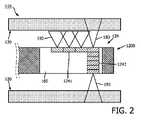
図2は、本開示の態様による、血管120により規定された内腔1200内のソリッドステートIVUS撮像システム100のトランスデューサアセンブリ110の概略的側面図である。トランスデューサアセンブリ110は、フレックス回路160上に取り付けられたトランスデューサ素子124を含む。様々なトランスデューサ構成が、トランスデューサ素子124で作成されることができる。図2に示されるように、いくつかの実施例において、トランスデューサ素子124は、複数の第1の超音波トランスデューサ1241及び複数の第2の超音波トランスデューサ1242を含む。これらの実施例において、第1の超音波トランスデューサ1241は、トランスデューサアセンブリ110の長手軸に沿って線形に配置される。トランスデューサアセンブリ110は、ソリッドステートIVUS撮像装置102(すなわち、可撓性細長部材102)の同じ長手軸を共有するので、第1の超音波トランスデューサ1241が、可撓性細長部材102の長手軸に平行に線形に配置されるということができる。加えて、これらの実施例において、第2の超音波トランスデューサ1242は、可撓性細長部材102の長手軸の周りに環状に配置されたトランスデューサアレイを構成する。 FIG. 2 is a schematic side view of
図2に表された実施例において、第1の超音波トランスデューサ1241は、第1の中心周波数で動作し、第2の超音波トランスデューサ1242は、第2の中心周波数で動作する。いくつかの例において、前記第1の中心周波数は、前記第2の中心周波数とは異なる。いくつかの他の例において、前記第1の中心周波数は、前記第2の中心周波数より高い。後者の例において、より高い第1の中心周波数を持つ第1の超音波トランスデューサ1241は、より高い空間解像度及びより小さい浸透深さにより特徴づけられる超音波画像データを取得する傾向にあるのに対し、より低い第2の中心周波数を持つ第2の超音波トランスデューサ1242は、より低い空間解像度及びより大きな浸透深さにより特徴づけられる超音波画像データを取得する傾向にある。結果として、第1の超音波トランスデューサ1241は、視野190を持ち、第2の超音波トランスデューサ1242は、視野180を持つ。有利には、この構成は、線形に配置された第1の超音波トランスデューサ1241が内腔1200を通って流れる血液を撮像することを可能にしながら、第2の超音波トランスデューサ1242で形成されたトランスデューサアレイが十分な深度で血管120を撮像することを可能にする。 In the embodiment depicted in FIG. 2, the first
一般に、前記超音波トランスデューサの前記中心周波数は、様々な実施例において、5MHzと100MHzとの間であることができる。例えば、前記超音波トランスデューサは、いくつかの実施例において、10MHz、20MHz、40MHz、45MHz、60MHzの典型的な中心周波数を持つことができる。例えば、単一の撮像装置は、例えば、10MHzの中心周波数を持つ第1の超音波素子と、20MHzの中心周波数を持つ第2の超音波素子と、60MHzの中心周波数を持つ第3の撮像素子とを含むことができる。10MHz及び20MHzの中心周波数は、有利に、血管壁構造に浸透することができるのに対し、60MHzの中心周波数は、有利に、血流を撮像することができる。 Generally, the center frequency of the ultrasound transducer can be between 5 MHz and 100 MHz in various embodiments. For example, the ultrasonic transducer can have typical center frequencies of 10 MHz, 20 MHz, 40 MHz, 45 MHz, 60 MHz in some embodiments. For example, a single imaging device may include, for example, a first ultrasound element with a center frequency of 10 MHz, a second ultrasound element with a center frequency of 20 MHz, and a third imaging element with a center frequency of 60 MHz. and Center frequencies of 10 MHz and 20 MHz can advantageously penetrate vessel wall structures, while center frequencies of 60 MHz can advantageously image blood flow.
異なる中心周波数に加えて、前記トランスデューサ素子の各々は、関連付けられた異なるパラメータを持つことができる。撮像データは、前記異なるパラメータに基づいてIVUS撮像データを生成するように処理されることができる。例えば、各トランスデューサ素子は、前記異なる中心周波数に対応する異なるゲイン値を持つことができる。いくつかの例において、撮像装置102は、各異なる中心周波数と関連付けられた超音波トランスデューサを制御する異なるコントローラ126を含むことができる。いくつかの実施例において、同じコントローラ126が、異なる中心周波数と関連付けれたトランスデューサを制御する。 In addition to different center frequencies, each of the transducer elements can have different parameters associated with it. Imaging data can be processed to generate IVUS imaging data based on the different parameters. For example, each transducer element can have a different gain value corresponding to the different center frequencies. In some examples, the
更に、線形に配置された第1の超音波トランスデューサ1241は、カラードップラ撮像を取得することができる。第1の超音波トランスデューサ1241の各々が、内腔1200内の血流に垂直な超音波伝搬の方向を持つが、カラードップラ撮像は、非ゼロドップラシフトを生成する様式で第1の超音波トランスデューサ1241の各々にエネルギ供給することにより可能にされる。例えば、第1の超音波トランスデューサ1241は、内腔1200内の血流の方向と反対の方向に順次的に(すなわち、一つずつ)エネルギ供給されることができる。この非ゼロドップラシフトは、カラードップラ撮像を可能にする。図2に示されないいくつかの実施例において、複数の第2の超音波トランスデューサ1242が、線形に配置された第1の超音波トランスデューサ1241と交互に配置されることができる。すなわち、第2の超音波トランスデューサ1242は、線形に配置された第1の超音波トランスデューサ1241の中の2つの間に置かれる。第1及び第2の超音波トランスデューサ1241及び1242の交互の線形アレイは、カラードップラ撮像目的で非ゼロドップラシフトを生成するようにエネルギ供給されることができる。 In addition, the linearly arranged
図3に示されるのは、本開示の態様による、ソリッドステートIVUS撮像システム100のトランスデューサアセンブリ110の概略的側面図である。図3に示されるように、いくつかの実施例において、第1の超音波トランスデューサ1241は、トランスデューサアセンブリ110の長手軸の周りに環状に配置された第1のトランスデューサアレイを形成し、第2の超音波トランスデューサ1242は、トランスデューサアセンブリ110の長手軸の周りに環状に配置された第2のトランスデューサアレイを形成する。第1の超音波トランスデューサ1241は、第1の中心周波数で動作し、第2の超音波トランスデューサは、第2の中心周波数で動作する。いくつかの例において、前記第1の中心周波数は、前記第2の中心周波数とは異なる。いくつかの他の例において、前記第1の中心周波数は、前記第2の中心周波数より高い。後者の場合、より高い第1の中心周波数を持つ第1の超音波トランスデューサ1241は、より高い空間解像度及びより小さい浸透深さにより特徴づけられた超音波画像データを取得する傾向にあるのに対し、より低い第2の中心周波数を持つ第2の超音波トランスデューサ1242は、より低い空間的解像度及びより大きい浸透深さにより特徴づけられる超音波画像データを取得する傾向にある。結果として、第1の超音波トランスデューサ1241は、視野190を持ち、第2の超音波トランスデューサ1242は、視野180を持つ。 Shown in FIG. 3 is a schematic side view of
図4に示されるのは、本開示の態様による、ソリッドステートIVUS撮像システム100のトランスデューサアセンブリ110の概略的側面図である。図4に示されるように、いくつかの実施例において、第1の超音波トランスデューサ1241は、トランスデューサアセンブリ110の長手軸に平行に線形に配置されたトランスデューサアレイを形成し、第2の超音波トランスデューサ1242の各々は、第1の超音波トランスデューサ1241の中の2つの間に置かれる。第1及び第2の超音波トランスデューサ1241及び1242は、間に置かれるので、逆も真である。第2の超音波トランスデューサ1242が、トランスデューサアセンブリ110の長手軸の周りに環状に配置されたトランスデューサアレイを形成し、第1の超音波トランスデューサ1241の各々が、第2の超音波トランスデューサ1242の2つの間に置かれるといわれることができる。結果として生じるトランスデューサアレイは、交互トランスデューサアレイと称されることができる。第1の超音波トランスデューサ1241は、第1の中心周波数で動作し、第2の超音波トランスデューサは、第2の中心周波数で動作する。いくつかの例において、前記第1の中心周波数は、前記第2の中心周波数とは異なる。いくつかの実施例において、トランスデューサ素子124は、交互トランスデューサアレイの2以上を含んでもよい。 Shown in FIG. 4 is a schematic side view of
トランスデューサのタイプに関して、一実施例において、第1及び第2の超音波トランスデューサ1241及び1242は、例えば、参照により全体的にここに組み込まれる米国特許6641540に開示されるように、高分子圧電材料を使用して微小電気機械システム(MEMS)基板上に製造された圧電性微小機械超音波トランスデューサ(PMUT)である。代替的な実施例において、第1及び第2の超音波トランスデューサ1241及び1242は、バルクPZTトランスデューサのような圧電性ジルコン酸塩トランスデューサ(PZT)トランスデューサ、容量性微小機械超音波トランスデューサ(cMUT)、単結晶圧電材料、他の適切な超音波送信器及び受信器、並びに/又はこれらの組み合わせである。いくつかの実施例において、第1の超音波トランスデューサ1241は、あるタイプのトランスデューサであり、第2の超音波トランスデューサ1242は、異なるタイプである。例えば、いくつかの例において、第1の超音波トランスデューサ1241は、CMUTであり、第2の超音波トランスデューサ1242は、PMUTである。 Regarding transducer types, in one embodiment, the first and second
第1及び第2の超音波トランスデューサ1241及び1242が取り付けられるフレックス回路160は、構造的支持及び電気結合に対する相互接続を提供する。フレックス回路214は、KAPTON(登録商標)(デュポンの商標)のような可撓性ポリイミド材料のフィルム層を含むように構成されてもよい。他の適切な材料は、ポリエステルフィルム、ポリイミドフィルム、ポリエチレンテレフタラートフィルム、又はポリエーテルイミドフィルム、他の可撓性プリント半導体基板並びにUpilex(宇部興産の登録商標)及びTEFLON(E.I.デュポンの登録商標)のような製品を含む。フレックス回路160のフィルム層の厚さは、一般に、最終的なアセンブルされたトランスデューサアセンブリ110における湾曲度に関連する。いくつかの実施例において、前記フィルム層は、5μmと100μmとの間であり、いくつかの特定の実施例に対して12.7μmと25.1μmとの間である。 A
ここで図1が参照され、ソリッドステートIVUS撮像システム100の動作が、記載される。伝送線バンドル又はケーブル112は、第1及び第2の超音波トランスデューサ1241及び1242に結合される複数の導体を含む。いくつかの実施例において、トランスデューサ1241、1242は、可撓性基板160上に形成される。他の実施例において、トランスデューサ1241及び/又はトランスデューサ1242は、別の基板に配置される。いくつかの例において、導体の必要な数を減少させるために、ソリッドステートIVUS撮像システム100は、第1及び第2の超音波トランスデューサ1241及び1242で形成されたトランスデューサアレイを制御するマイクロビームフォーマ集積回路(IC)を含むことができる。伝送線バンドル112は、装置102の近位端におけるPIMコネクタ114において終端する。PIMコネクタ114は、伝送線バンドル112をPIM104に電気的に結合し、IVUSコンソール106に結合されるPIM104にIVUS装置102を物理的に結合する。IVUSコンソール106は、第1及び第2の超音波トランスデューサ1241及び1242を別々に、同時に又は順次的にエネルギ供給するように動作可能である。IVUSコンソール106は、PIM104を経由してトランスデューサアセンブリ110からエコーデータ(時々、超音波データと称される)を受信するようにも動作可能であり、トランスデューサアセンブリ110を囲む媒体内の組織構造の画像を再構成するようにデータを処理する。例えば、図2により表される実施例において、IVUSコンソール106は、線形に配置された第1の超音波トランスデューサ1241にエネルギ供給するように動作可能であり、線形に配置された第1の超音波トランスデューサ1241により知覚された超音波データを受信する。IVUSコンソール106は、次いで、このような超音波データに基づいてカラードップラ超音波画像を生成するように動作可能である。加えて、IVUSコンソール106は、環状に配置された第2の超音波トランスデューサ1242にエネルギ供給するように動作可能であり、第2の超音波トランスデューサ1242により知覚された超音波データを受信する。IVUSコンソール106は、次いで、第2の超音波トランスデューサ1242により知覚された超音波データに基づいてグレイスケール超音波画像を生成することができる。更に、IVUSコンソール106は、前記カラードップラ超音波画像及びグレイスケール超音波画像をディスプレイ108に出力するように動作可能である。いくつかの例において、IVUSコンソール106は、グレイスケール超音波画像上にカラードップラ超音波画像を重ね合わせ、前記グレイスケール超音波画像上に重ね合わされたカラードップラ超音波画像を出力するように動作可能である。いくつかの例において、IVUSコンソール106は、異なる中心周波数で動作する複数の撮像素子により取得された撮像データを受信し、血管の3次元IVUS画像を再構成するように動作可能である。 Referring now to FIG. 1, the operation of solid state
図5は、本開示の一実施例によるIVUS撮像システム200を示す。本開示のいくつかの実施例において、IVUS撮像システム200は、回転式IVUS撮像システムである。これに関して、前記回転式IVUS撮像システムの主要なコンポーネントは、回転式IVUSカテーテル202、患者インタフェースモジュール(PIM)204、IVUSコンソール又は処理システム206(時々、制御及び処理装置と称される)、及びIVUSコンソール206により生成されたIVUS画像を表示するモニタ208である。カテーテル202は、いくつかの実施例において、超音波素子250を含む。以下により詳細に記載されるように、超音波素子250は、1より多い超音波トランスデューサを含んでもよい。PIM204は、カテーテル202をサポートする適切なインタフェース設計を実装する。いくつかの実施例によると、PIM204は、超音波素子250の動作を制御するように送信トリガ信号及び制御波形のシーケンスを生成する。 FIG. 5 shows an
超音波素子250は、血管内腔内に及び血管壁に向けて外側に前記カテーテルの長手軸に実質的に垂直に超音波信号を送信する。前記トランスデューサからの超音波放射は、PIM204から受信された対応する電気信号により起動される。超音波素子250は、血管組織(及び他の反射体)からの超音波エコー信号を、PIM204に通信される電気信号に変換する。
図6は、本開示の一実施例による、カテーテル202の概略的な部分切り取り斜視図を示す。図2は、回転式IVUSカテーテル202に関する追加の細部を示す。回転式カテーテル202は、撮像コア210と外側カテーテル/シースアセンブリを含む。撮像コア210は、PIM204に対する電気的及び機械的結合を提供する回転式インタフェース214により近位端において終端処理される可撓性駆動シャフトを含む(図1参照)。撮像コア210の前記可撓性駆動シャフトの遠位端は、超音波素子250を含むトランスデューサアセンブリ216に結合される。 FIG. 6 shows a schematic, partially cut-away perspective view of
カテーテル/シースアセンブリ212(時々、可撓性細長部材212と称される)は、回転式インタフェース214をサポートするハブ218を含み、軸受面、及びカテーテル202の回転要素と非回転要素との間の流体シールを提供する。いくつかの実施例において、ハブ218は、前記カテーテルの使用時に空気を追い出し、前記シースの内側内腔を超音波互換流体で充填するように生理食塩水が注入されるルアーロックフラッシュポート220を含む。超音波周波数は、空気により高度に減衰され、任意の空気‐固体又は空気‐液体界面において強力に反射されるので、生理食塩水又は他の同様な流体が、必要とされる。生理食塩水は、駆動シャフトを回転する生体適合潤滑剤をも提供する。いくつかの実施例において、ハブ218は、入れ子式管状要素と、カテーテル/シースアセンブリ212が伸長又は短縮されることを可能にするスライド流体シールを含むテレスコープ222に結合される。テレスコープ222は、カテーテル/シースアセンブリ212の遠位部分における音響的に透明な窓224内のトランスデューサハウジングの軸方向移動を容易化する。 Catheter/sheath assembly 212 (sometimes referred to as flexible elongated member 212) includes
いくつかの実施例において、窓224は、最小の減衰、反射又は屈折で前記トランスデューサと血管組織との間で超音波を容易に伝導する材料から製造された薄肉プラスチック管で構成される。カテーテル/シースアセンブリ212の近位シャフト226は、テレスコープ222と窓224との間のセグメントを橋渡しする。いくつかの実施例において、近位シャフト226は、滑性内側内腔及びカテーテル202に対する最適な剛性を提供する材料又は合成物で構成される。いくつかの実施例において、カテーテル/シースアセンブリ212及び/又は窓224は、参照により全体的にここに組み込まれる、2012年12月28日に出願されたINTRAVASCULAR ULTRASOUND CATHETER FOR MINIMIZING IMAGE DISTORTIONと題された米国特許仮出願第61/746958に記載されるようなフィーチャを含む。 In some embodiments,
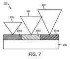
図7、8及び9は、本開示の態様による、様々なトランスデューサ構成を持つ回転式IVUS撮像システム200のトランスデューサ素子250の概略的側面図である。図7に示されるように、いくつかの実施例において、トランスデューサ素子250は、第1の中心周波数で動作する第1の超音波トランスデューサ2501、第2の中心周波数で動作する第2の超音波トランスデューサ2502、及び第3の中心周波数で動作する第3の超音波トランスデューサ2503を含む。いくつかの実施例において、第1、第2及び第3の超音波トランスデューサ2501、2502及び2503は、トランスデューサ素子250の長手軸に平行に線形に配置される。トランスデューサ素子250は、可撓性細長部材212の同じ長手軸を共有するので、第1、第2及び第3の超音波トランスデューサ2501、2502及び2503が、可撓性細長部材212の長手軸に平行に線形に配置されるといわれることができる。いくつかの例において、前記第1、第2及び第3の中心周波数は、互いに異なる。他の例において、前記第1の中心周波数は、前記第2の中心周波数より高く、前記第2の中心周波数は、前記第3の中心周波数より高い。これらの例において、第1の超音波トランスデューサ2501は、これら3つの超音波トランスデューサの中で最高の空間的解像度及び最小の浸透深さを持つ。第3の超音波トランスデューサ2503は、3つの中で最小の空間的解像度及び最大の浸透深さを持ち、第2の超音波トランスデューサ2502は、中間の空間的解像度及び浸透深さを持つ。結果として、第1の超音波トランスデューサ2501は、視野270を持ち、第2の超音波トランスデューサ2502は、視野280を持ち、第3の超音波トランスデューサ2503は、視野290を持つ。 7, 8 and 9 are schematic side views of
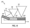
図8は、図7に示されるものとは異なる超音波トランスデューサ2501、2502及び2503の構成を示す。図7に示されるように、いくつかの実施例において、第1の超音波トランスデューサ2501は、トランスデューサアセンブリ216において平らに置かれず、角度Aで傾斜される。第1の超音波トランスデューサ2501が、遠位又は近位に傾斜されることができることに注意する。いくつかの例において、傾斜された第1の超音波トランスデューサ2501は、最高の中心周波数で動作する。いくつかの実施例において、前記第2の中心周波数は、前記第3の中心周波数より高い。結果として、図9において、第1の超音波トランスデューサ2501は、視野270を持ち、第2の超音波トランスデューサ2502は、視野280を持ち、第3の超音波トランスデューサ2503は、視野290を持つ。 FIG. 8 shows a different configuration of
図8に描かれた実施例において、IVUSコンソール又は処理システム206は、第1の超音波トランスデューサ2501から血管からのドップラ超音波データを取得するように構成されることができ、流体の流れの存在又は不在、方向及び量を決定するように前記データを分析することができる。ドップラ超音波は、受信された信号における位相変化として放射されたビームにより物体の移動を測定する。超音波が、移動している構造(例えば、血管内の赤血球細胞)から反射される場合、戻ってくる波の波長及び周波数が、シフトされる。前記移動している構造が、第1の超音波トランスデューサ2501に向かって移動している場合、周波数は増加する。前記移動している構造が、第1の超音波トランスデューサ2501から離れるように移動している場合、周波数は減少する。 In the embodiment depicted in FIG. 8, the IVUS console or
いくつかの実施例において、IVUSコンソール又は処理システム206は、ドップラ式、
Δf=(2f0Vcosθ)/C
を採用することができ、ここでΔfは、周波数シフトであり、f0は、送信波の周波数であり、Vは、反射する物体(例えば、赤血球細胞)の速度であり、θは、入射波と前記反射する物体の移動の方向との間の角度(すなわち、入射の角度)であり、Cは、媒体内での音の速度である。前記周波数シフトは、第1の超音波トランスデューサ2501が、血流の方向に平行に向けられ、θが、ゼロ度である場合(cosθ=1)に、最大である。前記周波数シフトは、トランスデューサ130が、血流の方向に垂直に向けられ、θが、90°である場合(cos90=0)に、不在である。より高いドップラ周波数シフトは、速度が増加され、入射波が、血流の方向に更にアラインされ、及び/又はより高い周波数が放射される場合に得られる。In some embodiments, the IVUS console or
Δf=(2f0 V cos θ)/C
whereΔf is the frequency shift, f is the frequency of the transmitted wave, V is the velocity of the reflecting object (e.g., red blood cell), and θ is the incident wave and the direction of motion of the reflecting object (ie the angle of incidence), and C is the speed of sound in the medium. The frequency shift is maximum when the first
図9は、図7及び8に示されるものとは異なる超音波トランスデューサ2501、2502及び2503の構成を示す。図9に示されるように、いくつかの実施例において、第1の超音波トランスデューサ2502及び第2の超音波トランスデューサ2502の両方が、トランスデューサアセンブリ216において平らに置かれず、それぞれ、角度A及びBで傾斜される。いくつかの実施例において、第1及び第2の超音波トランスデューサ2501及び2502は、中心に向けて傾斜される。すなわち、第1及び第2の超音波トランスデューサ2502及び2502の一方は、遠位に傾斜され、他方は、近位に傾斜される。第1及び第2の超音波トランスデューサ2501及び2502から伝搬する音波が、血流に平行な成分を含む限り、これらの両方が、カラードップラ超音波画像を生成するように超音波撮像データを取得するのに使用されることができる。図9に示される実施例において、第3の超音波トランスデューサ2503は、最小の中心周波数を持ち、可撓性細長部材212の長手軸に沿って第1の超音波トランスデューサ2501と第2の超音波トランスデューサ2502との間に配置される。結果として、図9において、第1の超音波トランスデューサ2501は、視野270を持ち、第2の超音波トランスデューサ2502は、視野280を持ち、第3の超音波トランスデューサ2503は、視野290を持つ。視野270、280及び290は、いくつかの例において、重複することができる。これに関して、計算装置は、(異なる中心周波数を持つ)複数のトランスデューサからのデータを使用して血管の単一の場所の単一のIVUS画像を生成することができる。 FIG. 9 shows a different configuration of
図10は、 本開示の態様による、患者の血管300の断面図である。血管300は、複数の層を含む。例えば、血管300は、内膜330及び中膜340を含む。内膜330は、内腔310を規定する内側血管壁320を持つ。IVUS装置102又はカテーテル202のような、IVUS装置400が、内腔310に対して配置される場合、IVUS装置400が、内膜330、中膜340、及び内腔310内を流れる血液の速度のフィーチャを解像するように異なる浸透深さの超音波撮像データを取得することができることは、有利である。有利には、本開示は、異なる中心周波数で動作する複数の超音波トランスデューサを含むIVUS撮像システムを提供する。本開示に開示されたIVUS撮像システムを用いて、カテーテルを実行する医師は、異なる目的で作られたIVUSカテーテルを患者の血管内に挿入する必要なしに、グレイスケール超音波画像だけでなく、カラードップラ画像をも取得することができる。 FIG. 10 is a cross-sectional view of a patient's
当業者は、上に記載された装置、システム及び方法が、様々な形で修正されることができることを認識する。したがって、当業者は、本開示により含まれる実施例が、上に記載された特定の典型的な実施例に限定されないことを理解する。これに関して、例示的な実施例が、図示及び記載されているが、広い範囲の修正、変更及び置換が、先行する開示において予期される。このような変形が、本開示の範囲から逸脱することなしに上記のものに対してなされてもよいと理解されたい。したがって、添付の請求項が、幅広く、本開示と一貫した様式で解釈されることは、適切である。 Those skilled in the art will recognize that the devices, systems and methods described above can be modified in various ways. Accordingly, those skilled in the art will appreciate that the examples encompassed by this disclosure are not limited to the specific exemplary examples described above. In this regard, while exemplary embodiments have been shown and described, a wide range of modifications, changes and substitutions are anticipated in the preceding disclosure. It should be understood that such modifications may be made to the above without departing from the scope of the present disclosure. Accordingly, it is appropriate that the appended claims be construed broadly and in a manner consistent with this disclosure.
Claims (8)
Translated fromJapanese前記可撓性細長部材の前記遠位部分に配置され、
前記可撓性細長部材の長手軸に平行に線形に配置され、第1の中心周波数で動作するように構成された複数の第1の超音波トランスデューサ、及び
前記第1の中心周波数とは異なる第2の中心周波数で動作するように構成された複数の第2の超音波トランスデューサを有し、前記可撓性細長部材の長手軸の周りに環状に配置された第2のトランスデューサアレイ、
を含む撮像アセンブリと、
を有する血管内超音波(IVUS)撮像装置において、
前記第1の超音波トランスデューサが、ドップラ超音波画像データを生成するように構成され、前記第2の超音波トランスデューサが、超音波画像データを生成するように構成される、
IVUS撮像装置。a flexible elongated member configured to be disposed within a lumen of a patient and having a proximal portion and a distal portion;
disposed at the distal portion of the flexible elongate member;
a plurality of first ultrasonic transducers arranged linearly parallel to the longitudinal axis of the flexible elongate member and configured to operate at a first center frequency; a second transducer array having a plurality of second ultrasonic transducers configured to operate at two center frequencies and arranged annularly about the longitudinal axis of the flexible elongate member;
an imaging assembly including
In an intravascular ultrasound (IVUS) imaging device having
wherein the first ultrasound transducer is configured to generate Doppler ultrasound image data and the second ultrasound transducer is configured to generate ultrasound image data;
IVUS imaging device.
前記可撓性細長部材の前記遠位部分に配置され、
前記可撓性細長部材の長手軸に平行に線形に配置され、第1の中心周波数で動作するように構成された第1の複数の超音波トランスデューサ、及び
前記可撓性細長部材の長手軸の周りに環状に配置された第2のトランスデューサアレイを有し、前記第1の中心周波数とは異なる第2の中心周波数で動作するように構成された第2の複数の超音波トランスデューサ、
を含む撮像アセンブリと、
前記第1の複数の超音波トランスデューサ及び前記第2の複数の超音波トランスデューサと通信し、
前記内腔の第2の超音波データを取得するように前記第2の複数の超音波トランスデューサにエネルギ供給し、
前記第2の超音波データに基づいてグレイスケール超音波画像を生成し、
前記内腔を流れる流体の第1の超音波データを取得するように前記第1の複数の超音波トランスデューサにエネルギ供給し、前記第1の超音波データがドップラ画像データであり、
前記第1の超音波データに基づいてカラードップラ超音波画像を生成し、
前記グレイスケール超音波画像及びカラードップラ超音波画像をディスプレイ出力する、
ように動作可能である制御及び処理装置と、
を有する、血管内超音波(IVUS)撮像システム。a flexible elongated member configured to be disposed within a lumen of a patient and having a proximal portion and a distal portion;
disposed at the distal portion of the flexible elongate member;
a first plurality of ultrasonic transducers arranged linearly parallel to the longitudinal axis of the flexible elongate member and configured to operate at a first center frequency; a second plurality of ultrasonic transducers having a second transducer array arranged annularly therearound and configured to operate at a second center frequency different from the first center frequency;
an imaging assembly including
in communication with the first plurality of ultrasonic transducers and the second plurality of ultrasonic transducers;
energizing the second plurality of ultrasonic transducers to acquire second ultrasonic data of the lumen;
generating a grayscale ultrasound image based on the second ultrasound data;
energizing the first plurality of ultrasonic transducers to acquire first ultrasonic data of fluid flowing through the lumen, the first ultrasonic data being Doppler image data;
generating a color Doppler ultrasound image based on the first ultrasound data;
Display-outputting the grayscale ultrasound image and the color Doppler ultrasound image;
a control and processing unit operable to
An intravascular ultrasound (IVUS) imaging system, comprising:
Applications Claiming Priority (3)
| Application Number | Priority Date | Filing Date | Title |
|---|---|---|---|
| US201762538640P | 2017-07-28 | 2017-07-28 | |
| US62/538,640 | 2017-07-28 | ||
| PCT/EP2018/070498WO2019020817A1 (en) | 2017-07-28 | 2018-07-27 | Intraluminal imaging devices with multiple center frequencies |
Publications (3)
| Publication Number | Publication Date |
|---|---|
| JP2020528322A JP2020528322A (en) | 2020-09-24 |
| JP2020528322A5 JP2020528322A5 (en) | 2021-07-26 |
| JP7199415B2true JP7199415B2 (en) | 2023-01-05 |
Family
ID=63311977
Family Applications (1)
| Application Number | Title | Priority Date | Filing Date |
|---|---|---|---|
| JP2020504021AActiveJP7199415B2 (en) | 2017-07-28 | 2018-07-27 | Intraluminal imager using multiple center frequencies |
Country Status (5)
| Country | Link |
|---|---|
| US (1) | US11576652B2 (en) |
| EP (1) | EP3658037B1 (en) |
| JP (1) | JP7199415B2 (en) |
| CN (1) | CN110958858B (en) |
| WO (1) | WO2019020817A1 (en) |
Families Citing this family (12)
| Publication number | Priority date | Publication date | Assignee | Title |
|---|---|---|---|---|
| JP6979882B2 (en) | 2015-06-24 | 2021-12-15 | ザ リージェンツ オブ ザ ユニヴァシティ オブ ミシガン | Tissue disruption therapy systems and methods for the treatment of brain tissue |
| AU2019389001B2 (en) | 2018-11-28 | 2025-08-14 | Histosonics, Inc. | Histotripsy systems and methods |
| US11813485B2 (en) | 2020-01-28 | 2023-11-14 | The Regents Of The University Of Michigan | Systems and methods for histotripsy immunosensitization |
| US12220544B2 (en)* | 2020-07-31 | 2025-02-11 | Avent, Inc. | Airway detection using ultrasound |
| JP2023540482A (en) | 2020-08-27 | 2023-09-25 | ザ リージェンツ オブ ザ ユニバーシティー オブ ミシガン | Ultrasonic transducer with transmitting and receiving functions for histotripsy |
| US11998393B2 (en)* | 2020-10-20 | 2024-06-04 | GE Precision Healthcare LLC | System and method of signal processing for ultrasound arrays with mechanically adjustable transducer shapes |
| CN114145713A (en)* | 2021-11-30 | 2022-03-08 | 深圳先进技术研究院 | A dual-frequency endoscopic catheter and imaging device |
| EP4608504A1 (en) | 2022-10-28 | 2025-09-03 | Histosonics, Inc. | Histotripsy systems and methods |
| CN116035621B (en)* | 2023-03-02 | 2023-06-16 | 深圳微创踪影医疗装备有限公司 | Intravascular ultrasound imaging method, intravascular ultrasound imaging device, intravascular ultrasound imaging computer equipment and intravascular ultrasound imaging storage medium |
| US20240315670A1 (en)* | 2023-03-22 | 2024-09-26 | Boston Scientific Scimed Inc. | Intravascular ultrasound catheter with bias correction |
| CN116363038B (en)* | 2023-06-02 | 2024-06-07 | 深圳英美达医疗技术有限公司 | Ultrasonic image fusion method, device, computer equipment and storage medium |
| WO2025172172A1 (en)* | 2024-02-14 | 2025-08-21 | Koninklijke Philips N.V. | Intravascular images with multiple frequencies and associated systems, devices, and methods |
Citations (4)
| Publication number | Priority date | Publication date | Assignee | Title |
|---|---|---|---|---|
| JP2006288679A (en) | 2005-04-11 | 2006-10-26 | Fuji Photo Film Co Ltd | Ultrasonic observation apparatus |
| JP2013542041A (en) | 2010-11-12 | 2013-11-21 | ボストン サイエンティフィック サイムド,インコーポレイテッド | System and method for manufacturing and using a rotary transducer for simultaneous imaging of blood flow and tissue |
| US20140236011A1 (en) | 2012-08-31 | 2014-08-21 | General Electric Company | Methods and systems for simultaneous interventional imaging and functional measurements |
| US20150305716A1 (en) | 2014-04-28 | 2015-10-29 | Koninklijke Philips N.V | Ultrasound Transducer Array Apparatus and Method of Imaging Using Transducer Arrays |
Family Cites Families (10)
| Publication number | Priority date | Publication date | Assignee | Title |
|---|---|---|---|---|
| US7226417B1 (en) | 1995-12-26 | 2007-06-05 | Volcano Corporation | High resolution intravascular ultrasound transducer assembly having a flexible substrate |
| CN1119974C (en) | 1999-12-30 | 2003-09-03 | 复旦大学 | Dual-ultrasonic doppler method for measuring blood flow speed |
| WO2002043593A1 (en) | 2000-12-01 | 2002-06-06 | The Cleveland Clinic Foundation | Miniature ultrasound transducer |
| US20060253028A1 (en) | 2005-04-20 | 2006-11-09 | Scimed Life Systems, Inc. | Multiple transducer configurations for medical ultrasound imaging |
| CN102781337A (en)* | 2010-01-19 | 2012-11-14 | 皇家飞利浦电子股份有限公司 | Imaging apparatus |
| US10869648B2 (en)* | 2012-05-11 | 2020-12-22 | Philips Image Guided Therapy Corporation | Device, system and method for flow imaging in the body using a swept transducer |
| US20150141833A1 (en) | 2012-06-01 | 2015-05-21 | North Carolina State University | Catheter device implementing high frequency, contrast imaging ultrasound transducer, and associated method |
| JP6129509B2 (en)* | 2012-10-04 | 2017-05-17 | 東芝メディカルシステムズ株式会社 | Ultrasonic medical apparatus and ultrasonic diagnostic imaging apparatus |
| CA2896510A1 (en) | 2012-12-28 | 2014-07-03 | Volcano Corporation | Intravascular ultrasound catheter for minimizing image distortion |
| CN104605892B (en) | 2015-01-21 | 2018-04-06 | 上海爱声生物医疗科技有限公司 | Single, more array element IVUS transducers and its forming method with bifrequency |
- 2018
- 2018-07-27JPJP2020504021Apatent/JP7199415B2/enactiveActive
- 2018-07-27USUS16/048,121patent/US11576652B2/enactiveActive
- 2018-07-27WOPCT/EP2018/070498patent/WO2019020817A1/ennot_activeCeased
- 2018-07-27EPEP18758812.4Apatent/EP3658037B1/enactiveActive
- 2018-07-27CNCN201880048925.XApatent/CN110958858B/enactiveActive
Patent Citations (4)
| Publication number | Priority date | Publication date | Assignee | Title |
|---|---|---|---|---|
| JP2006288679A (en) | 2005-04-11 | 2006-10-26 | Fuji Photo Film Co Ltd | Ultrasonic observation apparatus |
| JP2013542041A (en) | 2010-11-12 | 2013-11-21 | ボストン サイエンティフィック サイムド,インコーポレイテッド | System and method for manufacturing and using a rotary transducer for simultaneous imaging of blood flow and tissue |
| US20140236011A1 (en) | 2012-08-31 | 2014-08-21 | General Electric Company | Methods and systems for simultaneous interventional imaging and functional measurements |
| US20150305716A1 (en) | 2014-04-28 | 2015-10-29 | Koninklijke Philips N.V | Ultrasound Transducer Array Apparatus and Method of Imaging Using Transducer Arrays |
Also Published As
| Publication number | Publication date |
|---|---|
| EP3658037B1 (en) | 2023-10-11 |
| CN110958858B (en) | 2023-05-05 |
| US20190029642A1 (en) | 2019-01-31 |
| WO2019020817A1 (en) | 2019-01-31 |
| EP3658037A1 (en) | 2020-06-03 |
| CN110958858A (en) | 2020-04-03 |
| JP2020528322A (en) | 2020-09-24 |
| US11576652B2 (en) | 2023-02-14 |
Similar Documents
| Publication | Publication Date | Title |
|---|---|---|
| JP7199415B2 (en) | Intraluminal imager using multiple center frequencies | |
| US11013491B2 (en) | Method for focused acoustic computed tomography (FACT) | |
| JP6211599B2 (en) | Ultrasound catheter for imaging and blood flow measurement | |
| US20230293149A1 (en) | Phased array intravascular devices, systems, and methods utilizing photoacoustic and ultrasound techniques` | |
| US20210059642A1 (en) | Intravascular ultrasound device with impedance matching structure | |
| EP3697315B1 (en) | Digital rotational patient interface module | |
| US20150305716A1 (en) | Ultrasound Transducer Array Apparatus and Method of Imaging Using Transducer Arrays | |
| US12201474B2 (en) | Tissue and vascular pathway mapping using synchronized photoacoustic and ultrasound pullback techniques | |
| EP3435877A1 (en) | Intravascular devices, systems, and methods utilizing photoacoustic, ultrasound, and optical coherence tomography imaging techniques | |
| US11559207B2 (en) | Rotational intravascular devices, systems, and methods utilizing photoacoustic and ultrasound imaging techniques | |
| US10646200B2 (en) | Intravascular ultrasound imaging system with slip ring interface and associated devices, systems, and methods | |
| US20160015362A1 (en) | Intravascular devices, systems, and methods having motors | |
| Burrell et al. | Angioplasty under ultrasound? |
Legal Events
| Date | Code | Title | Description |
|---|---|---|---|
| A521 | Request for written amendment filed | Free format text:JAPANESE INTERMEDIATE CODE: A523 Effective date:20210602 | |
| A621 | Written request for application examination | Free format text:JAPANESE INTERMEDIATE CODE: A621 Effective date:20210602 | |
| A131 | Notification of reasons for refusal | Free format text:JAPANESE INTERMEDIATE CODE: A131 Effective date:20220524 | |
| A977 | Report on retrieval | Free format text:JAPANESE INTERMEDIATE CODE: A971007 Effective date:20220527 | |
| A521 | Request for written amendment filed | Free format text:JAPANESE INTERMEDIATE CODE: A523 Effective date:20220823 | |
| TRDD | Decision of grant or rejection written | ||
| A01 | Written decision to grant a patent or to grant a registration (utility model) | Free format text:JAPANESE INTERMEDIATE CODE: A01 Effective date:20221206 | |
| A61 | First payment of annual fees (during grant procedure) | Free format text:JAPANESE INTERMEDIATE CODE: A61 Effective date:20221220 | |
| R150 | Certificate of patent or registration of utility model | Ref document number:7199415 Country of ref document:JP Free format text:JAPANESE INTERMEDIATE CODE: R150 |