JP7199322B2 - Ranging device and ranging method - Google Patents
Ranging device and ranging methodDownload PDFInfo
- Publication number
- JP7199322B2 JP7199322B2JP2019154036AJP2019154036AJP7199322B2JP 7199322 B2JP7199322 B2JP 7199322B2JP 2019154036 AJP2019154036 AJP 2019154036AJP 2019154036 AJP2019154036 AJP 2019154036AJP 7199322 B2JP7199322 B2JP 7199322B2
- Authority
- JP
- Japan
- Prior art keywords
- phase
- distance
- carrier signals
- frequency
- received
- Prior art date
- Legal status (The legal status is an assumption and is not a legal conclusion. Google has not performed a legal analysis and makes no representation as to the accuracy of the status listed.)
- Active
Links
Images


Classifications
- G—PHYSICS
- G01—MEASURING; TESTING
- G01S—RADIO DIRECTION-FINDING; RADIO NAVIGATION; DETERMINING DISTANCE OR VELOCITY BY USE OF RADIO WAVES; LOCATING OR PRESENCE-DETECTING BY USE OF THE REFLECTION OR RERADIATION OF RADIO WAVES; ANALOGOUS ARRANGEMENTS USING OTHER WAVES
- G01S11/00—Systems for determining distance or velocity not using reflection or reradiation
- G01S11/02—Systems for determining distance or velocity not using reflection or reradiation using radio waves
- G01S11/06—Systems for determining distance or velocity not using reflection or reradiation using radio waves using intensity measurements
- G—PHYSICS
- G07—CHECKING-DEVICES
- G07C—TIME OR ATTENDANCE REGISTERS; REGISTERING OR INDICATING THE WORKING OF MACHINES; GENERATING RANDOM NUMBERS; VOTING OR LOTTERY APPARATUS; ARRANGEMENTS, SYSTEMS OR APPARATUS FOR CHECKING NOT PROVIDED FOR ELSEWHERE
- G07C9/00—Individual registration on entry or exit
- G07C9/00174—Electronically operated locks; Circuits therefor; Nonmechanical keys therefor, e.g. passive or active electrical keys or other data carriers without mechanical keys
- G07C9/00309—Electronically operated locks; Circuits therefor; Nonmechanical keys therefor, e.g. passive or active electrical keys or other data carriers without mechanical keys operated with bidirectional data transmission between data carrier and locks
- G—PHYSICS
- G01—MEASURING; TESTING
- G01S—RADIO DIRECTION-FINDING; RADIO NAVIGATION; DETERMINING DISTANCE OR VELOCITY BY USE OF RADIO WAVES; LOCATING OR PRESENCE-DETECTING BY USE OF THE REFLECTION OR RERADIATION OF RADIO WAVES; ANALOGOUS ARRANGEMENTS USING OTHER WAVES
- G01S13/00—Systems using the reflection or reradiation of radio waves, e.g. radar systems; Analogous systems using reflection or reradiation of waves whose nature or wavelength is irrelevant or unspecified
- G01S13/02—Systems using reflection of radio waves, e.g. primary radar systems; Analogous systems
- G01S13/06—Systems determining position data of a target
- G01S13/08—Systems for measuring distance only
- G01S13/32—Systems for measuring distance only using transmission of continuous waves, whether amplitude-, frequency-, or phase-modulated, or unmodulated
- B—PERFORMING OPERATIONS; TRANSPORTING
- B60—VEHICLES IN GENERAL
- B60R—VEHICLES, VEHICLE FITTINGS, OR VEHICLE PARTS, NOT OTHERWISE PROVIDED FOR
- B60R25/00—Fittings or systems for preventing or indicating unauthorised use or theft of vehicles
- B60R25/20—Means to switch the anti-theft system on or off
- B60R25/24—Means to switch the anti-theft system on or off using electronic identifiers containing a code not memorised by the user
- B60R25/245—Means to switch the anti-theft system on or off using electronic identifiers containing a code not memorised by the user where the antenna reception area plays a role
- G—PHYSICS
- G01—MEASURING; TESTING
- G01S—RADIO DIRECTION-FINDING; RADIO NAVIGATION; DETERMINING DISTANCE OR VELOCITY BY USE OF RADIO WAVES; LOCATING OR PRESENCE-DETECTING BY USE OF THE REFLECTION OR RERADIATION OF RADIO WAVES; ANALOGOUS ARRANGEMENTS USING OTHER WAVES
- G01S13/00—Systems using the reflection or reradiation of radio waves, e.g. radar systems; Analogous systems using reflection or reradiation of waves whose nature or wavelength is irrelevant or unspecified
- G01S13/74—Systems using reradiation of radio waves, e.g. secondary radar systems; Analogous systems
- G01S13/76—Systems using reradiation of radio waves, e.g. secondary radar systems; Analogous systems wherein pulse-type signals are transmitted
- G01S13/765—Systems using reradiation of radio waves, e.g. secondary radar systems; Analogous systems wherein pulse-type signals are transmitted with exchange of information between interrogator and responder
- G—PHYSICS
- G01—MEASURING; TESTING
- G01S—RADIO DIRECTION-FINDING; RADIO NAVIGATION; DETERMINING DISTANCE OR VELOCITY BY USE OF RADIO WAVES; LOCATING OR PRESENCE-DETECTING BY USE OF THE REFLECTION OR RERADIATION OF RADIO WAVES; ANALOGOUS ARRANGEMENTS USING OTHER WAVES
- G01S13/00—Systems using the reflection or reradiation of radio waves, e.g. radar systems; Analogous systems using reflection or reradiation of waves whose nature or wavelength is irrelevant or unspecified
- G01S13/74—Systems using reradiation of radio waves, e.g. secondary radar systems; Analogous systems
- G01S13/76—Systems using reradiation of radio waves, e.g. secondary radar systems; Analogous systems wherein pulse-type signals are transmitted
- G01S13/767—Responders; Transponders
- G—PHYSICS
- G01—MEASURING; TESTING
- G01S—RADIO DIRECTION-FINDING; RADIO NAVIGATION; DETERMINING DISTANCE OR VELOCITY BY USE OF RADIO WAVES; LOCATING OR PRESENCE-DETECTING BY USE OF THE REFLECTION OR RERADIATION OF RADIO WAVES; ANALOGOUS ARRANGEMENTS USING OTHER WAVES
- G01S13/00—Systems using the reflection or reradiation of radio waves, e.g. radar systems; Analogous systems using reflection or reradiation of waves whose nature or wavelength is irrelevant or unspecified
- G01S13/88—Radar or analogous systems specially adapted for specific applications
- G—PHYSICS
- G01—MEASURING; TESTING
- G01S—RADIO DIRECTION-FINDING; RADIO NAVIGATION; DETERMINING DISTANCE OR VELOCITY BY USE OF RADIO WAVES; LOCATING OR PRESENCE-DETECTING BY USE OF THE REFLECTION OR RERADIATION OF RADIO WAVES; ANALOGOUS ARRANGEMENTS USING OTHER WAVES
- G01S19/00—Satellite radio beacon positioning systems; Determining position, velocity or attitude using signals transmitted by such systems
- G01S19/38—Determining a navigation solution using signals transmitted by a satellite radio beacon positioning system
- G01S19/39—Determining a navigation solution using signals transmitted by a satellite radio beacon positioning system the satellite radio beacon positioning system transmitting time-stamped messages, e.g. GPS [Global Positioning System], GLONASS [Global Orbiting Navigation Satellite System] or GALILEO
- G01S19/53—Determining attitude
- G01S19/54—Determining attitude using carrier phase measurements; using long or short baseline interferometry
- G—PHYSICS
- G07—CHECKING-DEVICES
- G07C—TIME OR ATTENDANCE REGISTERS; REGISTERING OR INDICATING THE WORKING OF MACHINES; GENERATING RANDOM NUMBERS; VOTING OR LOTTERY APPARATUS; ARRANGEMENTS, SYSTEMS OR APPARATUS FOR CHECKING NOT PROVIDED FOR ELSEWHERE
- G07C9/00—Individual registration on entry or exit
- G07C9/00174—Electronically operated locks; Circuits therefor; Nonmechanical keys therefor, e.g. passive or active electrical keys or other data carriers without mechanical keys
- G07C9/00309—Electronically operated locks; Circuits therefor; Nonmechanical keys therefor, e.g. passive or active electrical keys or other data carriers without mechanical keys operated with bidirectional data transmission between data carrier and locks
- G07C2009/00555—Electronically operated locks; Circuits therefor; Nonmechanical keys therefor, e.g. passive or active electrical keys or other data carriers without mechanical keys operated with bidirectional data transmission between data carrier and locks comprising means to detect or avoid relay attacks
- G—PHYSICS
- G07—CHECKING-DEVICES
- G07C—TIME OR ATTENDANCE REGISTERS; REGISTERING OR INDICATING THE WORKING OF MACHINES; GENERATING RANDOM NUMBERS; VOTING OR LOTTERY APPARATUS; ARRANGEMENTS, SYSTEMS OR APPARATUS FOR CHECKING NOT PROVIDED FOR ELSEWHERE
- G07C2209/00—Indexing scheme relating to groups G07C9/00 - G07C9/38
- G07C2209/60—Indexing scheme relating to groups G07C9/00174 - G07C9/00944
- G07C2209/63—Comprising locating means for detecting the position of the data carrier, i.e. within the vehicle or within a certain distance from the vehicle
Landscapes
- Engineering & Computer Science (AREA)
- Radar, Positioning & Navigation (AREA)
- Remote Sensing (AREA)
- Physics & Mathematics (AREA)
- General Physics & Mathematics (AREA)
- Computer Networks & Wireless Communication (AREA)
- Mechanical Engineering (AREA)
- Electromagnetism (AREA)
- Radar Systems Or Details Thereof (AREA)
Description
Translated fromJapanese本発明の実施形態は、測距装置及び測距方法に関する。 An embodiment of the present invention relates to a ranging device and a ranging method.
近年、車の施錠・開錠を容易にするキーレスエントリシステムが多くの自動車に採用されている。この技術によれば、自動車のユーザは、自動車のキーと自動車間の通信を利用してドアを施錠・開錠することができる。更に近年、ユーザがキーに触れることなくドアを施錠・開錠したり、エンジンを始動させたりすることができるスマートキーシステムも広く普及している。 In recent years, many automobiles have adopted a keyless entry system that facilitates locking and unlocking of vehicles. According to this technology, the vehicle user can lock and unlock the door using the vehicle key and communication between the vehicle. Furthermore, in recent years, a smart key system has been widely used, which enables a user to lock/unlock a door or start an engine without touching a key.
一方で、攻撃者がキーと自動車間の通信に侵入し、車または車内物品を盗難する事件が多発している。この攻撃、すなわち所謂リレーアタックの防御策としてキーと自動車間の距離を測定し、距離が所定の距離以上と判断したときは、ドアの解錠などを禁止する策が検討されている。 On the other hand, there have been many incidents in which attackers intrude into communication between the key and the vehicle and steal the vehicle or items inside the vehicle. As a countermeasure against this attack, that is, a so-called relay attack, measures to measure the distance between the key and the vehicle and prohibit unlocking the door when the distance is judged to be greater than or equal to a predetermined distance are being studied.
しかし、測定される距離を伸ばすことと、マルチパスの影響を排除することの両方を実現するには、2つの装置間において、より多くの連続波信号の送受信が必要となり、測距に時間が掛かってしまう。 However, both increasing the measured distance and eliminating the effects of multipath would require more continuous wave signals to be sent and received between the two devices, making ranging more time consuming. It hangs.
そこで、実施形態は、マルチパスの影響を排除しつつ、測定できる距離を伸ばすことができる測距装置及び測距方法を提供することを目的とする。 Accordingly, an object of the embodiments is to provide a distance measuring device and a distance measuring method capable of extending the measurable distance while eliminating the influence of multipath.
実施形態の測距装置は、キャリア位相検出に基づいて距離を算出する測距装置において、少なくとも一方が移動自在な第1装置及び第2装置により取得した位相情報に基づいて前記第1装置と前記第2装置との間の距離を算出する算出部と、を有し、前記第1装置は、第1基準信号源と、前記第1基準信号源の出力を用いて、互いに周波数が異なる3つの第1キャリア信号を送信すると共に、前記3つの第1キャリア信号と周波数が同じ3つの第2キャリア信号を受信し、前記3つの周波数の中で、最も低い周波数と最も高い周波数の間の周波数は、前記最も低い周波数と前記最も高い周波数の平均値からずれた周波数である、第1送受信器と、前記3つの第2キャリア信号の各々の受信信号強度を測定する第1受信信号強度測定部と、前記3つの第2キャリア信号の3つの受信信号強度と、前記第2装置から受信した前記3つの第1キャリア信号の3つの受信信号強度から、前記平均値の周波数の受信信号強度を推定する推定部と、前記平均値の周波数の受信信号強度と、前記最も低い周波数の受信信号強度と、前記最も高い周波数の受信信号強度とから、前記距離に対するフェージング補正値を算出するフェージング補正値算出部と、を具備し、前記第2装置は、前記第1基準信号源とは独立に動作する第2基準信号源と、前記第2基準信号源の出力を用いて、前記3つの第2キャリア信号を送信すると共に、前記3つの第1キャリア信号を受信する第2送受信器と、前記3つの第1キャリア信号の各々の受信信号強度を測定する第2受信信号強度測定部とを有し、前記第2受信信号強度測定部で測定された前記3つの第1キャリア信号の各々の受信信号強度についての情報を前記第1装置に送信し、前記算出部は、前記3つの第1キャリア信号及び前記3つの第2キャリア信号の受信によって得られる位相検出結果を用いて、前記距離の算出を行うと共に、前記フェージング補正値を用いて、算出した前記距離を補正する。A range finder according to an embodiment is a range finder that calculates a distance based on carrier phase detection. and a calculation unit that calculates a distance from a second device, wherein the first device uses a first reference signal source and the output of the first reference signal source to generate three signals having different frequencies. Transmitting a first carrier signal and receiving three second carrier signals having the same frequency as the three first carrier signals, wherein among the three frequencies, the frequency between the lowest frequency and the highest frequency is , a first transceiver, which is a frequency shifted from the average value of the lowest frequency and the highest frequency; and a first received signal strength measuring unit for measuring the received signal strength of each of the three second carrier signals. estimating the received signal strength of the average frequencyfrom the three received signal strengths of the three second carrier signals and the three received signal strengths of the three first carrier signals received from the second device ; and a fading correction value calculator for calculating a fading correction value for the distance from the received signal strength of the average frequency, the received signal strength of the lowest frequency, and the received signal strength of the highest frequency. and wherein the second device comprises: a second reference signal source that operates independently of the first reference signal source; and the output of the second reference signal source to generate the three second carrier signals and a second transceiver that receives thethree first carrier signals; and a second received signal strength measuring unit that measures the received signal strength of each of the three first carrier signals; Information about the received signal strength of each of the three first carrier signals measured by the second received signal strength measuring unit is transmitted to the first device, and the calculating unit measures the three first carrier signals and the The distance is calculated using phase detection results obtained by receiving three second carrier signals, and the calculated distance is corrected using the fading correction value.
測距方式には時間検出方式、周波数差検出方式、位相検出方式などがあるが、実装の簡易性から、各装置間の通信によって各装置間の距離を求める通信型位相検出方式を採用した測距装置が注目されている。互いに初期位相が異なるため一般に通信型位相検出方式では、各装置間の基準信号は独立に動作することから、測距精度が大きく劣化する。 Distance measurement methods include the time detection method, frequency difference detection method, and phase detection method. Attention has been focused on range devices. Since the initial phases are different from each other, generally in the communication type phase detection system, the reference signals between the devices operate independently, so that the ranging accuracy is greatly deteriorated.
そこで、2つの装置間で2以上の連続波信号(CW:Continuous Wave)を送受信し、一方の装置で検出した各連続波信号の位相情報を他方の装置へ伝えることにより測距を可能にする測距方式が提案されている。その提案の測距方式によれば、対となる2つの装置の受信部で検出した2つの位相情報を用いて、所定の演算を施すことにより精度の良い距離を算出することができる。 Therefore, two or more continuous wave signals (CW: Continuous Wave) are transmitted and received between two devices, and the phase information of each continuous wave signal detected by one device is transmitted to the other device, thereby enabling distance measurement. A ranging scheme has been proposed. According to the proposed distance measurement method, two pieces of phase information detected by the receiving units of the two devices that form a pair are used to perform a predetermined calculation, whereby a highly accurate distance can be calculated.
また、そのような測距方式においてマルチパスの影響を排除する提案もされている。そのマルチマルチパスの影響を排除する提案による方法では、3波以上の連続波信号の受信電力を用いてマルチパスの影響を排除することができる。 Proposals have also been made to eliminate the effects of multipath in such ranging schemes. In the proposed method for eliminating the multipath effect, the received power of three or more continuous wave signals can be used to eliminate the multipath effect.
一方で、測距において測定できる距離を伸ばすことも望まれており、例えば3波以上の連続波信号を用いることにより、測定できる距離を伸ばすことができる。3つ以上の連続波信号を用いるとき、互いの周波数差が異なっている方が、より測定できる距離を伸ますことができる。 On the other hand, it is also desired to extend the measurable distance in ranging. For example, by using three or more continuous wave signals, the measurable distance can be extended. When three or more continuous wave signals are used, different frequency differences can extend the measurable distance.
以下、図面を参照して、マルチパスの影響を排除しつつ、測定できる距離を伸ばすことができる測距装置の実施形態を説明する。
(構成)
図1は、本実施形態に関わる測距装置を含む無線通信システムの構成図である。図2は、本実施形態に関わる無線通信システムが適用されるスマートキーシステムを説明するための構成図である。装置1と装置2の少なくとも一方が移動自在である。An embodiment of a distance measuring device capable of extending the measurable distance while eliminating the influence of multipath will be described below with reference to the drawings.
(Constitution)
FIG. 1 is a configuration diagram of a wireless communication system including a distance measuring device according to this embodiment. FIG. 2 is a configuration diagram for explaining a smart key system to which the wireless communication system according to this embodiment is applied. At least one of
スマートキーシステム100は、自動車Cと、自動車Cのドアの施錠・開錠及びエンジンの始動のためのキーKとを有して構成される。より詳しくは、スマートキーシステム100は、自動車Cに搭載された装置1と、キーKに内蔵された装置2との間で、所定のプロトコルに従って無線通信を行い、自動車においてキーKが正しく認証されると、ドアの施錠等を可能とする。後述するように、スマートキーシステム100では、キャリア位相検出に基づいて、装置1と装置2間の距離が算出される。 The
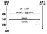
自動車Cに搭載された装置1のLF(Low Frequency)信号の受信可能エリアであるLFエリア内にユーザが入ると、認証が行われる。LF信号は、例えば130KHz帯の電波信号である、ビーコン信号である。キーKに内蔵された装置2は、ビーコン信号を受信すると、識別コード情報を送信し、装置1は、受信した識別コード情報に基づいて認証を行う。認証のための識別コード情報の送信には、UHF帯、例えば300MHz帯の電波信号が用いられる。認証されると、装置1と2間の測距が行われる。 When the user enters the LF area, which is the receivable area of the LF (Low Frequency) signal of the
図3は、キーKを保持するユーザUが、自動車Cの近傍に近づいてきたときの認証と測距の様子を説明するための図である。図3において、点線で示す範囲がLFエリアを示す。LFエリアは、ビーコン信号が届く範囲であり、例えば自動車Cの側面の中心から1.5から2m内のエリアである。ユーザUの保持する装置2がLFエリア内に入ると、認証後、装置1と装置2の間で2以上のキャリア信号である測距信号の送受信が複数回行われ、測距が複数回行われる。各キャリア信号は、無変調連続波(CW)である。ここでは、測距は、複数回行われているが、1回でもよい。測距信号は、サブギガヘルツ帯、例えば920MHz帯のキャリア信号である。 FIG. 3 is a diagram for explaining how authentication and distance measurement are performed when the user U holding the key K approaches the car C. As shown in FIG. In FIG. 3, the range indicated by the dotted line indicates the LF area. The LF area is the area within which the beacon signal reaches, for example, the area within 1.5 to 2 m from the center of the side of the vehicle C. When the
図4は、自動車Cの装置1とキーKの装置2との間で行われる無線信号の送受信シーケンスを示す図である。 FIG. 4 is a diagram showing a transmission/reception sequence of radio signals between the
装置1は、LF送信部12からビーコン信号を常に送信している。ビーコン信号は、LFエリア内にだけ届く信号であるので、装置2のLF受信部22は、LFエリア内にいるときだけ、ビーコン信号を受信することができる。 The
装置2は、ビーコン信号の受信に応じて、RF(Radio Frequency)送信部23から識別コード情報を送信すると同時に所定の待ち受け状態になる。装置1のRF受信部13が識別コード情報を受信すると、プロセッサ11は、受信した識別コード情報に基づいて認証を行う。プロセッサ11は、受信した識別コード情報に基づいて正しく認証できたときは、測距信号を送信し、続けて装置2からも測距信号が送信されて、装置1と装置2間の距離が測定される。 Upon receiving the beacon signal, the
装置1と装置2間の距離の測定は、日本国特開2018-155724号公報に開示のような方法により行われる。装置1と装置2のそれぞれにおいて算出された各キャリア信号の位相に基づいて、装置1と装置2間の距離が算出される。日本国特開2018-155724号公報に開示の方法によれば、装置1は、2以上(ここでは2つ)のキャリア信号を、第1の測距信号として送信し、装置2は、2以上(ここでは2つ)のキャリア信号を、第2の測距信号として送信する。装置2は、受信した第1の測距信号の2つのキャリア信号の位相差を検出し、装置1は、受信した第2の測距信号の2つのキャリア信号の位相差を検出する。装置2で検出された位相差の情報、すなわち位相差情報は、装置1に送信され、装置1は、装置1で検出した位相差と、装置2から受信した位相差情報とから装置1と装置2間の距離を所定の演算により算出する。 The measurement of the distance between the
なお、本実施形態では、装置2は、受信した2つのキャリア信号のそれぞれの位相の情報を、装置1へ送信し、装置1において、装置2から受信した2つの位相の情報から位相差を算出するようにしてもよい。 In this embodiment, the
装置1は、算出した装置1と装置2間の距離(以下、測定距離という)Rmに基づいて、リレーアタックの有無の判定を行うことができる。測定距離Rmが所定の距離、例えば2mを超えるときは、リレーアタックの可能性があるため、プロセッサ11は、例えば、自動車Cに対してドアの解錠を許可する信号を出力しない。測定距離Rmが所定の距離以下であるときは、キーKは自動車Cから所定の距離以内にあるため、プロセッサ11は、例えば、自動車Cに対してドアの解錠を許可する信号を出力する。その許可信号を受信すると、例えば、自動車Cのドアの解錠を制御する装置は、ドアに人間の手が触れたときに、ドアを解錠するための制御信号を出力する。 The
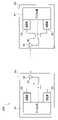
図1に示すように、装置1は、プロセッサ11と、LF送信部12と、RF受信部13と、測距部14を有する。装置2は、プロセッサ21と、LF受信部22と、RF送信部23と、測距部24を有する。 As shown in FIG. 1 , the
装置1のプロセッサ11は、中央処理装置(以下、CPUという)、ROM、RAMなどを含み、ROMには、LF送信部12、RF受信部13、測距部14の動作を制御する。プロセッサ11は、さらに、測距部14において受信した第2の測距信号に基づいて、位相差演算を行う。さらに、プロセッサ11は、その位相差演算により得られた位相差と、装置2から受信した位相情報に含まれる2つの位相の差とを用いて、測定距離Rmを算出し、算出された測定距離Rmに基づいて、所定の動作を行う。所定の動作は、上述したドアの解錠を許可する信号の出力などである。 The
装置2のプロセッサ21は、CPU、ROM、RAMなどを含み、ROMには、LF受信部22、RF送信部23及び測距部24の動作を制御する。プロセッサ21は、さらに、測距部24において受信した測距信号に基づいて、位相の検出すなわち測定を行い、検出された位相の位相情報を送信する。 The
なお、ここでは、プロセッサ11,21は、各機能を実現するソフトウエアプログラムを実行させるためのCPU、ROMなどを有して構成されているが、半導体装置、FPGA(Field Programmable Gate Array)などの電子回路により構成し、回路などにより各機能を実現するようにしてもよい。 Here, the
上述したように、各測距信号は、互いに周波数の異なる2つ以上(ここでは2つ)のキャリア信号を含む。日本国特開2018-155724号公報に開示されているように、第1の測距信号の2つの周波数のキャリア信号の位相差と、第2の測距信号の2つの周波数のキャリア信号の位相差との和に基づいて、装置1と装置2間の距離Rが測定距離Rmとして決定される。しかし、2つの位相差の和が360度を超えると、測定距離Rmの候補は、複数存在してしまうので、測距できない。 As described above, each ranging signal includes two or more (here, two) carrier signals with different frequencies. As disclosed in Japanese Patent Application Laid-Open No. 2018-155724, the phase difference between the two frequency carrier signals of the first ranging signal and the position of the two frequency carrier signals of the second ranging signal. Based on the sum with the phase difference, the distance R between
そこで、本実施形態では、測定距離Rmを伸ばすために、3つの周波数の測距信号を用いたバーニア測距も行う。 Therefore, in this embodiment, vernier distance measurement using distance measurement signals of three frequencies is also performed in order to extend the measurement distance Rm.
図5は、3つの周波数の測距信号を用いた場合における、位相差の和の情報に基づく距離の判定方法を説明するための図である。 FIG. 5 is a diagram for explaining a distance determination method based on information on the sum of phase differences when distance measurement signals of three frequencies are used.
図5の縦軸は、各装置1,2において検出された位相差の和(位相)であり、横軸は、測定距離Rm(メートル)である。太い実線は、第1のキャリア信号と第2のキャリア信号による位相差の和(位相)と、測定距離Rmの関係を示すグラフである。点線は、第2のキャリア信号と第3のキャリア信号による位相差の和(位相)と、測定距離Rmの関係を示すグラフである。細い実線は、第1のキャリア信号と第3のキャリア信号による位相差の和(位相)と、測定距離Rmの関係を示すグラフである。 The vertical axis of FIG. 5 is the sum (phase) of the phase differences detected by the
位相(位相差の和)毎に、2つの位相差の和が360度内においては、測定できる最大測定距離R1max、R2max、R3maxが存在する。各最大測定距離を超えると、複数の距離候補が存在するが、各位相により算出できる最大測定距離R1max、R2max、R3maxの最小公倍数を、最大測定可能距離Rmaxとしたときに、最大測定可能距離Rmax内において、複数の距離候補の中で、3つの位相から算出される3つの測定距離が一致する距離を、測定距離Rmとすることにより、測定距離Rmを伸ばすことができる。 For each phase (sum of phase differences), there are maximum measurable distances R1max, R2max, R3max within 360 degrees of the sum of two phase differences. When each maximum measurable distance is exceeded, a plurality of distance candidates exist. , the distance at which three measurement distances calculated from three phases are the same among a plurality of distance candidates can be set as the measurement distance Rm, whereby the measurement distance Rm can be extended.
図5において、第1のキャリア信号と第2のキャリア信号による位相差の和(位相)がθ1であり、第2のキャリア信号と第3のキャリア信号による位相差の和(位相)がθ2であり、第1のキャリア信号と第3のキャリア信号による位相差の和(位相)がθ3であるとき、3つの位相から算出される複数の距離の中で距離が一致するのは、距離Rkである。 In FIG. 5, the sum (phase) of the phase difference between the first carrier signal and the second carrier signal is θ1, and the sum (phase) of the phase difference between the second carrier signal and the third carrier signal is θ2. , and when the sum (phase) of the phase difference between the first carrier signal and the third carrier signal is θ3, the distance Rk is the one where the distances match among the plurality of distances calculated from the three phases. be.
黒丸で示すように、位相θ1の場合、距離R11,R12、R13、・・・、Rkも、算出される距離としては有り得る。複数の三角印は、位相θ2の場合の算出される距離を示す。X印は、位相θ3の場合の算出される距離を示す。位相θ1、位相θ2及びθ3について算出される距離が一致するのは、距離Rkのみとなる。 As indicated by black circles, in the case of phase θ1, distances R11, R12, R13, . A plurality of triangular marks indicate distances calculated in the case of phase θ2. The X mark indicates the distance calculated for the phase θ3. The distances calculated for the phases θ1, θ2, and θ3 match only at the distance Rk.
位相(位相差の和)毎に、2つの位相差の和が360度内においては、算出された各位相(位相差の和)θ1、θ2、θ3に対応して、それぞれR11、R21、R31が存在する。(R11+R1max)と(R21+R2max)と(R31+R3max)の最小公倍数が、距離Rkとなる。 For each phase (sum of phase differences), R11, R21, R31 corresponding to each calculated phase (sum of phase differences) θ1, θ2, θ3 within 360 degrees of the sum of two phase differences exists. The least common multiple of (R11+R1max), (R21+R2max) and (R31+R3max) is the distance Rk.
よって、算出された位相(位相差の和)がθ1、θ2、θ3であるとき、各位相に対応する距離が複数あっても、3つの位相により推定される距離が一致する距離が、正しい測定距離Rmとなる。 Therefore, when the calculated phases (the sum of the phase differences) are θ1, θ2, and θ3, even if there are multiple distances corresponding to each phase, the distance at which the distances estimated by the three phases match is the correct measurement. The distance is Rm.
なお、このとき、互いに異なる3つの周波数を用いるが、各キャリア信号において、第1のキャリア信号の周波数がf1であり、第2のキャリア信号の周波数がf2であり、第3のキャリア信号の周波数がf3であり、かつ、f2がf1とf3の平均値、すなわちf2=(f1+f3)/2であると、(f2-f1)=(f3-f2)となる。そのため、図5におけるグラフは、2本しか描かれないため、最大測定可能距離Rmaxは、短くなってしまう。そこで、最大測定可能距離Rmaxを大きくするために、周波数f2は、(f1+f3)/2からずれた値にして、3本のグラフが描かれるように設定される。 At this time, three different frequencies are used. In each carrier signal, the frequency of the first carrier signal is f1, the frequency of the second carrier signal is f2, and the frequency of the third carrier signal is f1. is f3 and f2 is the average of f1 and f3, ie f2=(f1+f3)/2, then (f2-f1)=(f3-f2). Therefore, since only two graphs are drawn in FIG. 5, the maximum measurable distance Rmax becomes short. Therefore, in order to increase the maximum measurable distance Rmax, the frequency f2 is deviated from (f1+f3)/2 and set so that three graphs are drawn.
一方で、測距の精度を高めるために、マルチパスの影響は排除されなければならない。そのために、3つ以上のキャリア信号の受信信号に基づきマルチパスの影響を排除することができる。例えば、日本国特開2018-155725号公報に開示の方法によれば、第1と第2のキャリア信号に第3のキャリア信号を追加して、マルチパスの影響を排除する技術が提案されている。 On the other hand, multipath effects must be eliminated in order to improve the accuracy of ranging. Therefore, multipath effects can be eliminated based on received signals of three or more carrier signals. For example, according to the method disclosed in Japanese Patent Application Laid-Open No. 2018-155725, a technique of adding a third carrier signal to the first and second carrier signals to eliminate the effects of multipath is proposed. there is
その提案に係る方法によれば、第1のキャリア信号の周波数がf1であり、第2のキャリア信号の周波数がf2であり、第3のキャリア信号の周波数をf3であるとすると、f2には、略(f1+f3)/2が用いられる。 According to the proposed method, if the frequency of the first carrier signal is f1, the frequency of the second carrier signal is f2, and the frequency of the third carrier signal is f3, then f2 is , approximately (f1+f3)/2 are used.
図6は、3つのキャリア信号の受信電力に基づきマルチパスの影響を排除した場合における実際の距離と測定距離の関係の例を示すグラフである。図6の横軸は、装置1と装置2間の実際の距離Rr(m)であり、縦軸は、上述した方式により算出された測定距離Rm(m)である。マルチパスなどがなければ、点線で示すように、上述した3つのキャリア信号を用いて得られた測定距離Rmは、実際の距離Rrと一致する。 FIG. 6 is a graph showing an example of the relationship between the actual distance and the measured distance when the influence of multipath is eliminated based on the received power of three carrier signals. The horizontal axis of FIG. 6 is the actual distance Rr (m) between the
しかし、太い実線で示すように、マルチパスの影響により、測定距離Rmは、実際の距離Rrと一致しなくなる場合がある。そこで、例えば、日本国特開2018-155725号公報に開示の方法を用いると、キャリア信号の受信電力からフェージング補正を行うことができる。日本国特開2018-155725号公報に開示の方法では、受信電力からフェージング補正値が算出され、そのフェージング補正値を用いて測定距離が補正される。 However, as indicated by the thick solid line, the measured distance Rm may not match the actual distance Rr due to the influence of multipath. Therefore, for example, by using the method disclosed in Japanese Patent Application Laid-Open No. 2018-155725, fading correction can be performed from the received power of the carrier signal. In the method disclosed in Japanese Patent Application Laid-Open No. 2018-155725, a fading correction value is calculated from received power, and the measured distance is corrected using the fading correction value.
図6において、太い実線は、フェージング補正をしないときの、実際の距離Rrと測定距離Rmとの関係を示すグラフである。細い実線は、フェージング補正をしたときの、実際の距離Rrと測定距離Rmとの関係を示すグラフである。フェージング補正を行うことにより、フェージング補正をしないときに比べて、測定距離Rmは、点線で示す実際の距離Rrに近くなっている。 In FIG. 6, the thick solid line is a graph showing the relationship between the actual distance Rr and the measured distance Rm without fading correction. A thin solid line is a graph showing the relationship between the actual distance Rr and the measured distance Rm when fading correction is performed. By performing the fading correction, the measured distance Rm is closer to the actual distance Rr indicated by the dotted line than when the fading correction is not performed.
受信電力に基づいてフェージング補正を行うとき、3つのキャリア信号の周波数は、略f2=(f1+f3)/2でなければならない。もしも、3つのうちの一つの周波数f2が、(f1+f3)/2からずれると、フェージング補正を行うことができない。 When performing fading correction based on received power, the frequencies of the three carrier signals should be approximately f2=(f1+f3)/2. If one of the three frequencies f2 deviates from (f1+f3)/2, fading correction cannot be performed.
図7は、周波数f2が、(f1+f3)/2にないときの、受信電力に基づきマルチパスの影響を排除した場合における実際の距離Rrと測定距離Rmの関係を示すグラフである。図7の細い線は、f2が、(f1+f3)/2から6%ずれた場合のグラフである。図7に示すように、3つのうちの一つの周波数f2が、(f1+f3)/2からずれると、フェージング補正ができない。 FIG. 7 is a graph showing the relationship between the actual distance Rr and the measured distance Rm when the influence of multipath is eliminated based on the received power when the frequency f2 is not at (f1+f3)/2. The thin line in FIG. 7 is the graph when f2 deviates from (f1+f3)/2 by 6%. As shown in FIG. 7, when one of the three frequencies f2 deviates from (f1+f3)/2, fading correction cannot be performed.
測定距離Rmを伸ばすためには、上述したように、互いに異なる周波数f1,f2,f3の3つのキャリア信号を用いる場合、周波数f2が(f1+f3)/2に一致しないように設定しなければならないが、フェージング補正のためには、周波数f2が(f1+f3)/2に一致するように設定しなければならない。その結果、測定距離Rmを長距離化することと、マルチパスの影響を排除するためのフェージング補正を行えるようにすることの両立を図るためには、互いに周波数が異なる4つの測距信号を用いなければならない。 In order to extend the measurement distance Rm, as described above, when using three carrier signals with mutually different frequencies f1, f2, and f3, the frequency f2 must be set so as not to coincide with (f1+f3)/2. , for fading correction, the frequency f2 must be set to match (f1+f3)/2. As a result, in order to increase the measurement distance Rm and to perform fading correction for eliminating the influence of multipath, four distance measurement signals having different frequencies are used. There must be.
例えば、周波数f1の第1のキャリア信号と、周波数f2(=(f1+f3)/2)の第2のキャリア信号と、周波数f3の第3のキャリア信号と、周波数f4(f2からずれた周波数)の第4のキャリア信号の、4つのキャリア信号の送受信を、装置1と装置2の間で行う必要がある。 For example, a first carrier signal with frequency f1, a second carrier signal with frequency f2 (=(f1+f3)/2), a third carrier signal with frequency f3, and a frequency f4 (a frequency shifted from f2). It is necessary to transmit and receive four carrier signals of the fourth carrier signal between
しかし、図3で示したように、自動車CとキーK間で認証された後に測距が行われるため、キャリア信号の送受信の回数は少ない方が、測距時間の短縮のためには好ましく、かつバッテリで駆動されるキーKの消費電力の観点からも好ましい。 However, as shown in FIG. 3, since the distance measurement is performed after the vehicle C and the key K are authenticated, it is preferable to reduce the number of transmission/reception of the carrier signal in order to shorten the distance measurement time. Moreover, it is preferable from the viewpoint of power consumption of the key K driven by a battery.
そこで、本実施形態では、4つではなく3つのキャリア信号を用いて、測定距離Rmを長距離化することと、マルチパスの影響を排除するためのフェージング補正を行えるようにすることの両立を図るようにしている。 Therefore, in the present embodiment, three carrier signals are used instead of four to achieve both a longer measurement distance Rm and a fading correction for eliminating the influence of multipath. I am trying to
本実施形態では、第1~第3の測距信号である3つのキャリア信号が、装置1と装置2間で送受信される。装置1は、第1~第3の測距信号である3つのキャリア信号を、第1キャリア信号として装置2へ送信し、装置2は、第1~第3の測距信号である3つのキャリア信号を、第2キャリア信号として装置1へ送信する。第1、第2及び第3のキャリア信号の周波数は、それぞれf1、f2、f3としたとき、f2は、(f1+f3)/2と一致せず、(f1+f3)/2からずれた周波数である。そして、3つのキャリア信号の受信電力から、fc(=(f1+f3)/2)の受信電力を推定して、その推定した受信電力を用いてフェージング補正を行う。 In this embodiment, three carrier signals, first to third ranging signals, are transmitted and received between
図8は、受信信号強度の推定を説明するための図である。図8の横軸は、周波数(f)であり、縦軸は、受信信号強度(RSSI)である。 FIG. 8 is a diagram for explaining estimation of received signal strength. The horizontal axis of FIG. 8 is frequency (f), and the vertical axis is received signal strength indicator (RSSI).
周波数f1、f2、f3の3つのキャリア信号の受信信号強度y0、y1、y2が、測定される。図8において、測定された3つの受信信号強度は、y0、y1、y2で示されている。周波数f2は、周波数fc(=(f1+f3)/2)からずれた周波数である。 The received signal strengths y0, y1, y2 of the three carrier signals at frequencies f1, f2, f3 are measured. In FIG. 8, the three measured received signal strengths are indicated by y0, y1 and y2. The frequency f2 is a frequency shifted from the frequency fc (=(f1+f3)/2).
周波数fcの受信信号強度は、測定されないため、測定された受信信号強度y0、y1、y2から二次の多項式近似演算により推定される。周波数fcの測距信号の受信信号強度は、推定され、図8においてycestで示されている。 Since the received signal strength at frequency fc is not measured, it is estimated from the measured received signal strengths y0, y1, y2 by a second-order polynomial approximation. The received signal strength of the ranging signal at frequency fc is estimated and denoted by ycest in FIG.
よって、周波数f1、f2、f3の3つのキャリア信号の送受信のシーケンスで、測定距離Rmを長距離化することと、マルチパスの影響を排除するためのフェージング補正を行えるようにすることの両立を図ることができる。 Therefore, in the transmission/reception sequence of three carrier signals of frequencies f1, f2, and f3, it is possible to increase the measurement distance Rm and to perform fading correction for eliminating the influence of multipath. can be planned.
図9は、本実施形態に関わる測距装置の構成図である。測距装置200は、測距部14と24とを含んで構成され、キャリア位相検出に基づいて装置1と装置2間の距離を算出する。装置1と装置2の少なくとも一方は、移動自在である。測距部14は、装置1に含まれ、デジタル部31、送信部32、受信部33、アンテナ34及びアンテナスイッチ35を含む。デジタル部31、送信部32、受信部33及びアンテナスイッチ35は、1つ又は2以上の半導体装置として構成される。測距部24は、装置2に含まれ、デジタル部41、送信部42、受信部43、アンテナ44及びアンテナスイッチ45を含む。デジタル部41、送信部42、受信部43及びアンテナスイッチ45、1つ又は2以上の半導体装置として構成される。 FIG. 9 is a configuration diagram of a distance measuring device according to this embodiment. Distance measuring
装置1のデジタル部31は、プロセッサ11からの制御信号に応じて、送信部32、受信部33及びアンテナスイッチ35を制御する。装置2のデジタル部41は、プロセッサ21からの制御信号に応じて、送信部42、受信部43及びアンテナスイッチ45を制御する。 The
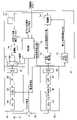
図10は、装置1の測距部14の回路図である。デジタル部31は、例えば半導体装置上のデジタル回路により構成される。デジタル部31は、基準発振器50、制御部51、位相測定部52、キー側位相受信部53、バーニア測距演算部54、測距演算部55、RSSI測定部56、RSSI推定部57及びフェージング補正値算出部58を含む。 FIG. 10 is a circuit diagram of the
基準発振器50は、測距部14内の動作の基本クロック信号を生成する基準信号源である。制御部51は、プロセッサ11からの測距開始のトリガーとなるコマンド信号(以下、測距開始トリガー信号という)を受信すると、所定の測距シーケンスの動作を行うように、位相測定部52などの各ブロックの動作タイミングを制御する。 The
位相測定部52は、装置2からの各キャリア信号の位相を測定する。位相測定部52は、受信部33において受信した装置2からの3つのキャリア信号の位相を測定する回路である。すなわち、位相測定部52は、受信した3つの第2キャリア信号の各々の位相を測定する。 A
キー側位相受信部53は、装置2から受信した、装置2において測定された3つのキャリア信号の位相情報及び受信信号強度(RSSI)情報を受信する回路である。 The key-
バーニア測距演算部54は、装置1で受信した周波数f1,f2、f3の3つのキャリア信号の位相と、装置2から受信した位相情報(周波数f1,f2、f3の3つのキャリア信号の位相)とから、装置1と装置2間の距離を算出する。よって、バーニア測距演算部54は、装置1及び装置2において取得された位相情報に基づいて装置1と装置2との間の距離を算出する算出部を構成する。特に、バーニア測距演算部54は、位相測定部52において測定された3つの第2キャリア信号の各々の位相についての情報と、位相測定部72において測定された3つの第1キャリア信号の各々の位相についての情報とを、位相情報として、距離を算出する。バーニア測距演算部54は、後述するフェージング補正値算出部58からのフェージング補正値を用いて、算出した距離を補正して、プロセッサ11に出力する。 The vernier ranging
測距演算部55は、装置1で受信した周波数f1とf3の2つのキャリア信号の位相と、装置2から受信した位相情報(周波数f1、f3の2つのキャリア信号の位相)とから、装置1と装置2間の距離を算出する。よって、測距演算部55は、装置1及び装置2において取得された位相情報に基づいて装置1と装置2との間の距離を算出する算出部を構成する。特に、測距演算部55は、位相測定部52において測定された最も低い周波数f1のキャリア信号と最も高い周波数f3のキャリア信号の各々の位相についての情報と、位相測定部72において測定された最も低い周波数f1のキャリア信号と最も高い周波数f3のキャリア信号の各々の位相についての情報とを、位相情報として、距離を算出する。測距演算部55も、後述するフェージング補正値算出部58からのフェージング補正値を用いて、算出した距離を補正して、プロセッサ11に出力する。 Based on the phases of the two carrier signals with frequencies f1 and f3 received by the
バーニア測距演算部54は、測距演算部55の最大測定距離よりも遠い距離を測定するために、互いに異なる周波数f1,f2,f3の3つのキャリア信号を用い、特に、周波数f2は、(f1+f3)/2からずれた周波数である。 The
測距演算部55は、周波数f1とf3の2つのキャリア信号の位相差を用いて測距を行う。すなわち、測距演算部55は、測距部14で受信した周波数f1,f3の2つのキャリア信号の位相差と、測距部24で受信した周波数f1,f3の2つのキャリア信号の位相差とを用いて、距離を算出する。 The distance
バーニア測距演算部54及び測距演算部55は、フェージング補正算出部58からの補正値を用いて、算出された距離情報を補正する。 The vernier
よって、バーニア測距演算部54と測距演算部55は、3つの第1キャリア信号及び3つの第2キャリア信号の受信によって得られる位相検出結果を用いて、距離の算出を行うと共に、フェージング補正値を用いて、算出した距離を補正する算出部を構成する。 Therefore, the vernier ranging
そのため、位相測定部52で得られた周波数f1,f2,f3の3つのキャリア信号の3つの位相の情報は、バーニア測距演算部54に供給され、位相測定部52で得られた周波数f1,f3の2つのキャリア信号の2つの位相の情報は、測距演算部55に供給される。 Therefore, the information of the three phases of the three carrier signals of frequencies f1, f2, and f3 obtained by the
なお、ここでは、装置1の測距部14がバーニア測距演算部54と測距演算部55を有しているのは、バーニア測距演算部54で算出された距離情報と測距演算部55で算出された距離情報とを使い分けができるようにするためである。例えば、算出された距離が短いときは、測距演算部55の距離情報を用い、算出された距離が長いときは、バーニア測距演算部54の距離情報を用いる、というような使い分けを可能にするためである。 Here, the
RSSI測定部56は、受信した3つのキャリア信号の受信電力から各々の受信信号強度(RSSI)を測定すると共に、装置2で測定された3つのキャリア信号の各々の受信信号強度(RSSI)の情報も格納する。よって、RSSI測定部56は、装置2からの3つの第2キャリア信号の各々の受信信号強度を測定する受信信号強度測定部を構成する。 The
RSSI推定部57は、上述したように、装置1と装置2の各々で測定された3つのキャリア信号の受信電力を用いて、f1とf3の真ん中の周波数fc(=(f1+f3)/2)の受信電力を算出して推定する。すなわち、RSSI推定部57は、3つの第2キャリア信号の3つの受信信号強度と、装置2から受信した3つの第1キャリア信号の3つの受信信号強度から、平均値の周波数fcの受信信号強度を推定する。 As described above, the
具体的には、RSSI推定部57は、装置1で受信して測定された3つのキャリア信号の受信電力に基づく受信信号強度を、装置2で測定された3つのキャリア信号の受信電力に基づく受信信号強度を用いて、周波数毎の平均値を算出する。そして、RSSI推定部57は、上述したように、周波数fcのキャリア信号の受信信号強度を、上述したように、3つの受信信号強度から求めた二次関数から推定する。 Specifically, the
なお、ここでは、RSSI推定部57は、装置1で受信して測定された3つのキャリア信号の受信信号強度と、装置2で測定された3つのキャリア信号の受信信号強度とを用いているが、装置1又は装置2で受信して測定された3つのキャリア信号の受信信号強度だけから、周波数fcのキャリア信号の受信信号強度を推定してもよい。よって、RSSI推定部57は、3つの第1キャリア信号の3つの受信信号強度及び3つの第2キャリア信号の3つの受信信号強度の少なくとも1つから、前記平均値の周波数の受信信号強度を推定する推定部を構成する。 Here, the
フェージング補正値算出部58は、推定した周波数fcの受信信号強度と、周波数f1とf3の各受信信号強度とを用いて、フェージング補正のための補正値を算出し、測距演算部55とバーニア測距演算部54に供給する。よって、フェージング補正値算出部58は、平均値の周波数fcの受信信号強度と、最も低い周波数の受信信号強度f1と、最も高い周波数f3の受信信号強度とから、距離に対するフェージング補正値を算出する。 The fading
なお、一点鎖線で示すように、フェージング補正のための補正値は、バーニア測距演算部54には供給せず、測距演算部55へのみ供給するようにしてもよい。 As indicated by the dashed line, the correction value for fading correction may be supplied only to the
次に、送信部32について説明する。デジタル部31は、基準発振器50に基づく無変調信号(CW)のデータを生成して、送信部32へ出力する。 Next, the
送信部32は、デジタルアナログ変換器(以下、DACと略す)61、ローパスフィルタ(以下、LPFと略す)62、変調器(MOD)63及び増幅器64を含むアナログ回路である。 The
DAC61は、連続波(CW)のためのデジタルデータをデジタル部31から受信して、アナログ信号に変換する。よって、デジタル部31は、連続波(CW)のためのデジタルデータを生成する。
DAC61のアナログ信号は、LPF62を通過して、変調器63に入力される。変調器63は、制御部51からの周波数切替信号に応じて、LPF62の出力信号を周波数変調する。ここでは、LPF62からのアナログ信号は、上述した周波数、f1、f3、f4の周波数のいずれかに変調される。 The analog signal of
変調器63は、制御部51からの周波数切替信号に応じて、入力信号を変調して、周波数f1,f2,f3のいずれか1つの周波数の信号を生成する。 The
増幅器64は、パワーアンプであり、変調器63の出力信号を増幅して、アンテナスイッチ35を経由して、アンテナ34へ供給する。アンテナスイッチ35は、制御部51からのアンテナ制御信号に応じて、アンテナ34を、送信部32又は受信部33と接続するように動作する。 The
次に、受信部33について説明する。受信部33は、ローノイズアンプ(以下、LNAと略す)65と、復調器(DEMOD)66と、LPF67及びアナログデジタル変換器(以下、ADCと略す)68を含むアナログ回路である。 Next, the
LNA65は、アンテナスイッチ35を経由して受信したアンテナ34からの受信信号を増幅して、復調器66へ出力する。復調器66は、制御部51からの周波数切替信号に応じて、LNA65の出力信号を復調してベースバンド信号を出力する。
復調器66の出力信号は、LPF67を通ってADC68に供給される。ADC68は、LPF67の出力信号をデジタル信号に変換してデジタル部31へ出力する。 The output signal of
以上のように、送信部32と受信部33は、基準発振器50の出力を用いて、互いに周波数が異なる3つ(f1、f2、f3)の第1キャリア信号を送信すると共に、3つの第1キャリア信号と周波数が同じ3つの第2キャリア信号を装置2から受信し、3つの周波数の中で、最も低い周波数と最も高い周波数の間の周波数は、最も低い周波数と最も高い周波数の平均値からずれた周波数である、第1送受信器を構成する。 As described above, the
図11は、装置2の測距部24の回路図である。デジタル部41は、例えば半導体装置上のデジタル回路により構成される。デジタル部41は、基準発振器70、制御部71、位相測定部72、RSSI測定部73、格納部74、受信信号検出部75、変調部76及びセレクタ77を含む。 FIG. 11 is a circuit diagram of the
基準発振器70は、測距部24内の動作の基本クロック信号を生成する基準信号源である。基準発振器70は、装置1の基準発振器50とは独立に動作する。制御部71は、プロセッサ21からの測距開始トリガー信号を受信すると、所定の測距シーケンスの動作を行うように、位相測定部72などの各ブロックの動作タイミングを制御する。プロセッサ21は、識別コード情報を送信した後、測距開始トリガー信号を測距部24の制御部71へ出力する。 A
位相測定部72は、装置1からの各キャリア信号の位相を測定する。測定された各キャリア信号の位相の情報は、格納部74に格納される。すなわち、位相測定部72は、受信した3つの第1キャリア信号の各々の位相を測定する。 A
RSSI測定部73は、周波数f1、f2、f3のキャリア信号の受信電力から受信信号強度を測定する。測定された各キャリア信号の受信信号強度の情報は、格納部74に格納される。 The
格納部74は、上述したように、各キャリア信号の位相及び受信信号強度の情報を格納するレジスタである。 The
受信信号検出部75は、装置1からの最初のキャリア信号の受信を検出する。受信信号検出部75は、最初のキャリア信号を受信すると、最初のキャリア信号を受信したことを制御部71へ通知する。 The received
変調部76は、位相情報と受信信号強度情報を、送信するための信号に変調する。ここでは、位相情報と受信信号強度情報は、各情報のデジタルデータに対応するIQ信号に変調される。すなわち、測距部24において測定された位相情報と受信信号強度情報は、装置1の測距部14へ送信される。
セレクタ77は、制御部71からのデータ選択信号に応じて、基準発振器70に基づく連続波(CW)のデータ又は変調部76の出力信号を選択して送信部42に出力する。 The
制御部71は、プロセッサ21からの距離開始トリガー信号を受信すると、自動車Cの装置1からのキャリア信号の待ち受け状態となる。 When the
次に、送信部42について説明する。送信部42は、DAC81、LPF82、変調器(MOD)83及び増幅器84を含むアナログ回路である。 Next, the
DAC81は、デジタル部41からの連続波(CW)のためのデジタルデータを受信して、アナログ信号に変換する。よって、デジタル部81は、連続波(CW)のためのデジタルデータを生成する。
DAC81のアナログ信号は、LPF82を通過して、変調器83に入力される。変調器83は、制御部71からの周波数切替信号に応じて、LPF82の出力信号を周波数変調する。ここでは、LPF82からのアナログ信号は、上述した周波数、f1、f3、f4の周波数のいずれかに変調される。 The analog signal of
変調器83は、制御部71からの周波数切替信号に応じて、入力信号を変調して、周波数f1,f2,f3のいずれか1つの周波数の信号を生成する。 The
増幅器84は、パワーアンプであり、変調器83の出力信号を増幅して、アンテナスイッチ45を経由して、アンテナ44へ供給する。アンテナスイッチ45は、制御部71からのアンテナ制御信号に応じて、アンテナ44を、送信部42又は受信部43と接続するように動作する。 The
次に、受信部43について説明する。受信部43は、ローノイズアンプ(以下、LNAと略す)85と、復調器(DEMOD)86と、LPF87及びアナログデジタル変換器(以下、ADCと略す)88を含むアナログ回路である。 Next, the receiving
LNA85は、アンテナスイッチ45を経由して受信したアンテナ44からの受信信号を増幅して、復調器86へ出力する。復調器86は、制御部71からの周波数切替信号に応じて、LNA85の出力信号を復調してベースバンド信号を出力する。
復調器86の出力信号は、LPF87を通ってADC88に供給される。ADC88は、LPF87の出力信号をデジタル信号に変換してデジタル部41へ出力する。 The output signal of
以上のように、送信部42と受信部43は、基準発振器70の出力を用いて、3つの第2キャリア信号を送信すると共に、装置1から3つの第1キャリア信号を受信する第2送受信器を構成する。
(作用)
次に、測距の処理の流れを説明する。As described above, the transmitting
(Action)
Next, the flow of distance measurement processing will be described.
図12と図13は、装置1における測距処置の流れの例を示すフローチャートである。図14と図15は、装置2における測距処置の流れの例を示すフローチャートである。図16は、装置1と装置2間で送受信される複数の信号のシーケンス図である。 12 and 13 are flowcharts showing an example of the flow of distance measurement processing in the
本実施形態では、3つの周波数f1,f2,f3の3つのキャリア信号が用いられ、推定誤差を除去して正確な測距のために、各周波数のキャリア信号が2往復する送受信シーケンスが採用されている。 In the present embodiment, three carrier signals of three frequencies f1, f2, and f3 are used, and a transmission/reception sequence is adopted in which the carrier signal of each frequency makes two round trips in order to eliminate estimation errors and accurately measure distance. ing.
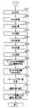
図12の処理は、プロセッサ11からの測距開始トリガー信号を受信すると、制御部51により実行される。図14の処理は、プロセッサ21からの測距開始トリガー信号を受信すると、制御部71により実行される。 The process of FIG. 12 is executed by the
図12に示すように、制御部51は、第1の周波数f1のキャリア信号をアンテナ34から送受信するために、第1の周波数設定を行う(ステップ(以下、Sと略す)1)。S1の処理は、制御部51が、周波数切替信号を変調器63に出力することにより行われる。 As shown in FIG. 12, the
S1の後、制御部51は、送信部32を制御して、設定された周波数f1のキャリア信号を送信する(S2)。 After S1, the
一方、装置2では、図14に示すように、制御部71は、第1の周波数f1のキャリア信号をアンテナ44から送受信するために、第1の周波数設定を行う(S101)。S101の処理は、制御部71が、周波数切替信号を変調器83に出力することにより行われる。 On the other hand, in the
制御部71は、装置1の測距部14からのキャリア信号を受信するまで待ち状態となる(S102)。測距部24は、装置1の測距部14からのキャリア信号を受信すると(S103)、RSSI測定部73は、受信したキャリア信号の受信電力から受信信号強度(RSSI)を計算し(S104)、位相測定部72は、受信したキャリア信号の位相を計算する(S105)。 The
S105の後、制御部71は、設定された周波数f1のキャリア信号を送信する(S106)。S106の後、さらに、制御部71は、設定された周波数f1のキャリア信号を送信する(S107)。 After S105, the
装置1の測距部14は、装置2の測距部24のS106に対応するキャリア信号を受信すると(S3)、RSSI測定部56は、受信信号の受信電力から受信信号強度(RSSI)を計算し(S4)、位相測定部52は、受信したキャリア信号の位相を計算する(S5)。 When the ranging
続いて、測距部14は、装置2の測距部24のS107に対応するキャリア信号を受信し(S6)、制御部51は、受信信号の受信電力から受信信号強度(RSSI)を計算し(S7)、受信したキャリア信号の位相を計算する(S8)。 Subsequently, the
S8の後、制御部51は、設定された周波数f1のキャリア信号を送信する(S9)。S9の後、制御部51は、第2の周波数f2のキャリア信号をアンテナ34から送受信するために、第2の周波数設定を行う(S10)。S10の処理は、制御部51が、周波数切替信号を変調器63に出力することにより行われる。 After S8, the
装置2では、図14において、装置1の測距部14のS9に対応するキャリア信号を受信し(S108)、制御部71は、受信信号の受信電力から受信信号強度(RSSI)を計算し(S109)、受信したキャリア信号の位相を計算する(S110)。 In FIG. 14, the
図16において、以上の処理が、キャリア信号の送受信シーケンスSC1を示す。 In FIG. 16, the above processing indicates the transmission/reception sequence SC1 of the carrier signal.
制御部51は、S10の後、送信部32を制御して、設定された周波数f2のキャリア信号を送信する(S11)。 After S10, the
装置2では、S110の後、制御部71は、第2の周波数f2のキャリア信号をアンテナ34から送受信するために、第2の周波数設定を行う(S111)。S111の処理は、制御部71が、周波数切替信号を変調器83に出力することにより行われる。 In the
装置2では、測距部24は、装置1の測距部14のS11に対応するキャリア信号を受信し(S112)、制御部71は、受信信号の受信電力から受信信号強度(RSSI)を計算し(S113)、受信したキャリア信号の位相を計算する(S114)。 In the
S114の後、制御部71は、設定された周波数f2のキャリア信号を送信する(S115)。S115の後、さらに、制御部71は、設定された周波数f2のキャリア信号を送信する(S116)。 After S114, the
装置1では、測距部14は、装置2の測距部24のS115に対応するキャリア信号を受信し(S12)、制御部51は、受信信号の受信電力から受信信号強度(RSSI)を計算し(S13)、受信したキャリア信号の位相を計算する(S14)。 In the
続いて、測距部14は、装置2の測距部24のS116に対応するキャリア信号を受信し(S15)、制御部51は、受信信号の受信電力から受信信号強度(RSSI)を計算し(S16)、受信したキャリア信号の位相を計算する(S17)。 Subsequently, the
S17の後、制御部51は、設定された周波数f2のキャリア信号を送信する(S18)。S18の後、制御部51は、第3の周波数f3のキャリア信号をアンテナ34から送受信するために、第3の周波数設定を行う(S19)。S1の処理は、制御部51が、周波数切替信号を変調器63に出力することにより行われる。 After S17, the
装置2では、図14において、装置1の測距部14のS18に対応するキャリア信号を受信し(S117)、図15に示すように、制御部71は、受信信号の受信電力から受信信号強度(RSSI)を計算し(S118)、受信したキャリア信号の位相を計算する(S119)。 In
図16において、以上のS10~S18及びS111~S119の処理が、キャリア信号の送受信シーケンスSC2を示す。 In FIG. 16, the above processing of S10 to S18 and S111 to S119 represents the transmission/reception sequence SC2 of the carrier signal.
装置1では、制御部51は、S19の後、送信部32を制御して、設定された周波数f3のキャリア信号を送信する(S20)。 In the
装置2では、S119の後、制御部71は、第3の周波数f3のキャリア信号をアンテナ34から送受信するために、第3の周波数設定を行う(S120)。S119の処理は、制御部71が、周波数切替信号を変調器83に出力することにより行われる。 In the
装置2では、測距部24は、装置1の測距部14のS20に対応するキャリア信号を受信し(S121)、制御部71は、受信信号の受信電力から受信信号強度(RSSI)を計算し(S122)、受信したキャリア信号の位相を計算する(S123)。 In the
S123の後、制御部71は、設定された周波数f3のキャリア信号を送信する(S124)。S124の後、さらに、制御部71は、設定された周波数f3のキャリア信号を送信する(S125)。 After S123, the
測距部14は、装置2の測距部24のS124に対応するキャリア信号を受信し(S21)、制御部51は、受信信号の受信電力から受信信号強度(RSSI)を計算し(S22)、受信したキャリア信号の位相を計算する(S23)。 The
続いて、測距部14は、装置2の測距部24のS125に対応するキャリア信号を受信し(S24)、制御部51は、受信信号の受信電力から受信信号強度(RSSI)を計算し(S25)、受信したキャリア信号の位相を計算する(S26)。 Subsequently, the
S26の後、制御部51は、設定された周波数のキャリア信号を送信する(S27)。 After S26, the
装置2では、図15に示すように、装置1の測距部14のS27に対応するキャリア信号を受信し(S126)、制御部71は、受信信号の受信電力から受信信号強度(RSSI)を計算し(S127)、受信したキャリア信号の位相を計算する(S128)。 As shown in FIG. 15, the
図16において、以上のS19~S27及びS120~S126の処理が、キャリア信号の送受信シーケンスSC3を示す。 In FIG. 16, the above processing of S19 to S27 and S120 to S126 represents the transmission/reception sequence SC3 of the carrier signal.
そして、装置2では、制御部71は、S105,S110,S114,S119,S123,S128において計算された各位相の位相情報と、S104,S109,S113,S118,S122,S127において計算された受信信号強度(RSSI)情報を、送信する(S129)。 In the
装置1では、制御部51は、キーKの装置2からの位相情報と受信信号強度(RSSI)情報を受信する(S28)。 In
装置1では、RSSI推定部57は、S4,S7,S13,S16,S22,S25において算出された6つの周波数f1,f2,f3の6つの受信信号強度と、装置2から受信した6つの受信信号強度とから、周波数fcの受信信号強度を推定する(S29)。 In the
例えば、f1,f2,f3の周波数毎に、装置1における受信信号強度を算出すると共に、装置2における受信信号強度を算出し、f1,f2,f3の周波数毎の受信信号強度の平均値を求め、求めた3つの平均値を用いて、周波数fcの受信信号強度が推定される。 For example, for each frequency f1, f2, f3, the received signal strength in the
なお、上述したように、周波数fcの受信信号強度の推定は、装置1において測定されて算出された3つの周波数の受信信号強度だけから行ってもよい。 As described above, the reception signal strength of frequency fc may be estimated only from the reception signal strengths of the three frequencies measured and calculated by the
装置1では、フェージング補正値算出部58は、S29で推定して得られたfcの受信信号強度と、測定されたf1,f3の受信信号強度を用いて、フェージング補正値を計算する(S30)。 In the
測距演算部55は、f1,f3についての位相情報から距離を算出し、フェージング補正値を用いて、算出した距離を補正する(S31)。 The
さらに、バーニア測距演算部54は、f1,f2,f3の位相情報から距離を算出し、フェージング補正値を用いて、バーニア測距により算出した距離を補正する(S32)。 Further, the vernier ranging
バーニア測距演算部54と測距演算部55において算出された2つの距離情報は、プロセッサ11へ供給される。プロセッサ11は、2つの距離情報のいずれか一方が、所定の距離を超えるときは、リレーアタックが行われたと判断して、自動車Cの制御装置に対してドアの解錠を許可する信号を出力しない。プロセッサ11は、2つの距離情報の両方が、所定の距離以下であるときは、リレーアタックが行われていないと判断して、自動車Cの制御装置に対してドアの解錠を許可する信号を出力する。 Two pieces of distance information calculated by the vernier
以上のように、上述した実施形態によれば、マルチパスの影響を排除しつつ、測定できる距離を伸ばすことができる測距装置及び測距方法を提供することができる。 As described above, according to the above-described embodiments, it is possible to provide a distance measuring apparatus and a distance measuring method capable of extending the measurable distance while eliminating the influence of multipath.
本発明の実施形態を説明したが、この実施形態は、例として例示したものであり、発明の範囲を限定することは意図していない。この新規な実施形態は、その他の様々な形態で実施されることが可能であり、発明の要旨を逸脱しない範囲で、種々の省略、置き換え、変更を行うことができる。この実施形態やその変形は、発明の範囲や要旨に含まれると共に、特許請求の範囲に記載された発明とその均等の範囲に含まれる。 While embodiments of the invention have been described, the embodiments are illustrated by way of example and are not intended to limit the scope of the invention. This novel embodiment can be embodied in various other forms, and various omissions, replacements, and modifications can be made without departing from the scope of the invention. This embodiment and its modifications are included in the scope and gist of the invention, and are included in the scope of the invention described in the claims and its equivalents.
1、2 装置、11 プロセッサ、12 LF送信部、13 RF受信部、14 測距部、21 プロセッサ、22 LF受信部、23 RF送信部、24 測距部、31 デジタル部、32 送信部、33 受信部、34 アンテナ、35 アンテナスイッチ、41 デジタル部、42 送信部、43 受信部、44 アンテナ、45 アンテナスイッチ、50 基準発振器、51 制御部、52 位相測定部、53 キー側位相受信部、54 バーニア測距演算部、55 測距演算部、56 受信信号強度測定部、57 推定部、58 フェージング補正値算出部、61 デジタルアナログ変換器、62 ローパスフィルタ、63 変調器、64 増幅器、65 ローノイズアンプ、66 復調器、67 ローパスフィルタ、68 アナログデジタル変換器、70 基準発振器、71 制御部、72 位相測定部、73 測定部、74 格納部、75 受信信号検出部、76 変調部、77 セレクタ、81 デジタル部、82 ローパスフィルタ、83 変調器、84 増幅器、85 ローノイズアンプ、86 復調器、87 ローパスフィルタ、88 アナログデジタル変換器、100 スマートキーシステム、200 測距装置。
Claims (5)
Translated fromJapanese少なくとも一方が移動自在な第1装置及び第2装置により取得した位相情報に基づいて前記第1装置と前記第2装置との間の距離を算出する算出部と、を有し、
前記第1装置は、
第1基準信号源と、
前記第1基準信号源の出力を用いて、互いに周波数が異なる3つの第1キャリア信号を送信すると共に、前記3つの第1キャリア信号と周波数が同じ3つの第2キャリア信号を受信し、前記3つの周波数の中で、最も低い周波数と最も高い周波数の間の周波数は、前記最も低い周波数と前記最も高い周波数の平均値からずれた周波数である、第1送受信器と、
前記3つの第2キャリア信号の各々の受信信号強度を測定する第1受信信号強度測定部と、
前記3つの第2キャリア信号の3つの受信信号強度と、前記第2装置から受信した前記3つの第1キャリア信号の3つの受信信号強度から、前記平均値の周波数の受信信号強度を推定する推定部と、
前記平均値の周波数の受信信号強度と、前記最も低い周波数の受信信号強度と、前記最も高い周波数の受信信号強度とから、前記距離に対するフェージング補正値を算出するフェージング補正値算出部と、を具備し、
前記第2装置は、
前記第1基準信号源とは独立に動作する第2基準信号源と、
前記第2基準信号源の出力を用いて、前記3つの第2キャリア信号を送信すると共に、前記3つの第1キャリア信号を受信する第2送受信器と、
前記3つの第1キャリア信号の各々の受信信号強度を測定する第2受信信号強度測定部とを有し、
前記第2受信信号強度測定部で測定された前記3つの第1キャリア信号の各々の受信信号強度についての情報を前記第1装置に送信し、
前記算出部は、前記3つの第1キャリア信号及び前記3つの第2キャリア信号の受信によって得られる位相検出結果を用いて、前記距離の算出を行うと共に、前記フェージング補正値を用いて、算出した前記距離を補正する、測距装置。In a distance measuring device that calculates distance based on carrier phase detection,
a calculation unit that calculates a distance between the first device and the second device based on phase information acquired by a first device and a second device, at least one of which is movable;
The first device is
a first reference signal source;
Using the output of the first reference signal source, transmitting three first carrier signals having different frequencies, and receiving three second carrier signals having the same frequency as the three first carrier signals, a first transceiver, wherein a frequency between the lowest frequency and the highest frequency among the two frequencies is a frequency shifted from the average value of the lowest frequency and the highest frequency;
a first received signal strength measuring unit that measures the received signal strength of each of the three second carrier signals;
estimating the received signal strength of the average frequencyfrom the three received signal strengths of the three second carrier signals and the three received signal strengths of the three first carrier signals received from the second device; Department and
a fading correction value calculation unit that calculates a fading correction value for the distance from the received signal strength of the average frequency, the received signal strength of the lowest frequency, and the received signal strength of the highest frequency. death,
The second device is
a second reference signal source operating independently of the first reference signal source;
a second transceiver for transmitting the three second carrier signals and receiving the three first carrier signals using the output of the second reference signal source;
a second received signal strength measuring unit that measures the received signal strength of each of the three first carrier signals;
transmitting information about the received signal strength of each of the three first carrier signals measured by the second received signal strength measuring unit to the first device;
The calculator calculates the distance using phase detection results obtained by receiving the three first carrier signals and the three second carrier signals, and calculates the distance using the fading correction value. A ranging device that corrects the distance.
前記第2装置は、前記第2送受信器において受信した前記3つの第1キャリア信号の各々の位相を測定する第2位相測定部を有し、
前記算出部は、前記第1位相測定部において測定された前記最も低い周波数のキャリア信号と前記最も高い周波数のキャリア信号の各々の位相についての第1情報と、前記第2位相測定部において測定された前記最も低い周波数のキャリア信号と前記最も高い周波数のキャリア信号の各々の位相についての第2情報とを、前記位相情報として、前記距離を算出する、請求項1に記載の測距装置。The first device has a first phase measuring unit that measures the phase of each of the three second carrier signals received by the first transceiver,
The second device has a second phase measuring unit that measures the phase of each of the three first carrier signals received by the second transceiver,
The calculator calculates first information about the phase of each of the lowest frequency carrier signal and the highest frequency carrier signal measured by the first phase measuring unit, and the first information measured by the second phase measuring unit. 2. The range finder according to claim 1, wherein the distance is calculated using second information about phases of the carrier signal with the lowest frequency and the carrier signal with the highest frequency as the phase information.
前記第2装置は、前記第2送受信器において受信した前記3つの第1キャリア信号の各々の位相を測定する第2位相測定部を有し、
前記算出部は、前記第1位相測定部において測定された前記3つの第2キャリア信号の各々の位相についての第1情報と、前記第2位相測定部において測定された前記3つの第1キャリア信号の各々の位相についての第2情報とを、前記位相情報として、前記距離を算出する、請求項1に記載の測距装置。The first device has a first phase measuring unit that measures the phase of each of the three second carrier signals received by the first transceiver,
The second device has a second phase measuring unit that measures the phase of each of the three first carrier signals received by the second transceiver,
The calculator calculates first information about the phase of each of the three second carrier signals measured by the first phase measuring unit and the three first carrier signals measured by the second phase measuring unit. 2. The range finder according to claim 1, wherein said distance is calculated using second information about each phase of said phase information as said phase information.
前記第2装置は、前記第2送受信器で受信した前記3つの第1キャリア信号の各位相についての情報を前記第1装置に送信する、請求項1に記載の測距装置。The calculation unit is provided in the first device,
2. The ranging device according to claim 1, wherein said second device transmits information about each phase of said three first carrier signals received at said second transceiver to said first device.
第1装置から、第1基準信号源の出力を用いて、互いに周波数が異なる3つの第1キャリア信号を送信し、
第2装置から、前記第1基準信号源とは独立に動作する第2基準信号源の出力を用いて、前記3つの第1キャリア信号と周波数が同じ3つの第2キャリア信号を送信し、
前記3つの周波数の中で、最も低い周波数と最も高い周波数の間の周波数は、前記最も低い周波数と前記最も高い周波数の平均値からずれた周波数であり、
前記第1装置において、前記3つの第2キャリア信号の各々の受信信号強度を測定し、
前記第2装置において、前記3つの第1キャリア信号の各々の受信信号強度を測定し、
前記第2装置において、測定された前記3つの第1キャリア信号の各々の受信信号強度についての情報を前記第1装置に送信し、
前記3つの第2キャリア信号の3つの受信信号強度と、前記第2装置から受信した前記3つの第1キャリア信号の3つの受信信号強度から、前記平均値の周波数の受信信号強度を推定し、
前記平均値の周波数の受信信号強度と、前記最も低い周波数の受信信号強度と、前記最も高い周波数の受信信号強度とから、前記距離に対するフェージング補正値を算出し、
前記3つの第1キャリア信号及び前記3つの第2キャリア信号の受信によって得られる位相検出結果を用いて、前記距離の算出を行うと共に前記フェージング補正値を用いて、算出した前記距離を補正する、測距方法。In a ranging method for calculating distance based on carrier phase detection,
Transmitting three first carrier signals with different frequencies from the first device using the output of the first reference signal source,
transmitting from a second device three second carrier signals having the same frequency as the three first carrier signals using the output of a second reference signal source operating independently of the first reference signal source;
Among the three frequencies, the frequency between the lowest frequency and the highest frequency is a frequency that deviates from the average value of the lowest frequency and the highest frequency,
measuring, in the first device, the received signal strength of each of the three second carrier signals;
measuring, at the second device, the received signal strength of each of the three first carrier signals;
at the second device, transmitting information about the measured received signal strength of each of the three first carrier signals to the first device;
estimating the received signal strength of the average frequencyfrom the three received signal strengths of the three second carrier signals and the three received signal strengths of the three first carrier signals received from the second device ;
calculating a fading correction value for the distance from the received signal strength at the average frequency, the received signal strength at the lowest frequency, and the received signal strength at the highest frequency;
Using phase detection results obtained by receiving the three first carrier signals and the three second carrier signals, calculating the distance and correcting the calculated distance using the fading correction value; Ranging method.
Priority Applications (4)
| Application Number | Priority Date | Filing Date | Title |
|---|---|---|---|
| JP2019154036AJP7199322B2 (en) | 2019-08-26 | 2019-08-26 | Ranging device and ranging method |
| CN202010021178.XACN112433206B (en) | 2019-08-26 | 2020-01-09 | Distance measuring device and distance measuring method |
| US16/802,262US11462064B2 (en) | 2019-08-26 | 2020-02-26 | Distance measurement apparatus and distance measurement method |
| EP20175696.2AEP3786659B1 (en) | 2019-08-26 | 2020-05-20 | Distance measurement apparatus and distance measurement method |
Applications Claiming Priority (1)
| Application Number | Priority Date | Filing Date | Title |
|---|---|---|---|
| JP2019154036AJP7199322B2 (en) | 2019-08-26 | 2019-08-26 | Ranging device and ranging method |
Publications (2)
| Publication Number | Publication Date |
|---|---|
| JP2021032742A JP2021032742A (en) | 2021-03-01 |
| JP7199322B2true JP7199322B2 (en) | 2023-01-05 |
Family
ID=70802610
Family Applications (1)
| Application Number | Title | Priority Date | Filing Date |
|---|---|---|---|
| JP2019154036AActiveJP7199322B2 (en) | 2019-08-26 | 2019-08-26 | Ranging device and ranging method |
Country Status (4)
| Country | Link |
|---|---|
| US (1) | US11462064B2 (en) |
| EP (1) | EP3786659B1 (en) |
| JP (1) | JP7199322B2 (en) |
| CN (1) | CN112433206B (en) |
Families Citing this family (3)
| Publication number | Priority date | Publication date | Assignee | Title |
|---|---|---|---|---|
| JP2021188924A (en)* | 2020-05-26 | 2021-12-13 | 株式会社東海理化電機製作所 | Control device and program |
| JP7539345B2 (en)* | 2021-05-24 | 2024-08-23 | 株式会社東海理化電機製作所 | Communication device and program |
| CN114415104A (en)* | 2021-12-22 | 2022-04-29 | 珠海云洲智能科技股份有限公司 | A distance measuring method, distance measuring device and electronic equipment |
Citations (5)
| Publication number | Priority date | Publication date | Assignee | Title |
|---|---|---|---|---|
| JP2008187652A (en) | 2007-01-31 | 2008-08-14 | Sanyo Electric Co Ltd | Receiver and communication method |
| JP2013165351A (en) | 2012-02-09 | 2013-08-22 | Hitachi Kokusai Electric Inc | Radio communication system and radio communication method |
| JP2014513271A (en) | 2011-02-25 | 2014-05-29 | シズベル テクノロジー エス.アール.エル. | Method for estimating distance from radio transmitter to receiver, method for calculating position of mobile terminal, mobile terminal, and position specifying device |
| JP2018155725A (en) | 2017-03-17 | 2018-10-04 | 株式会社東芝 | Distance measuring device and distance measurement method |
| JP2018155724A (en) | 2017-03-17 | 2018-10-04 | 株式会社東芝 | Ranging device and ranging method |
Family Cites Families (16)
| Publication number | Priority date | Publication date | Assignee | Title |
|---|---|---|---|---|
| JP4265686B2 (en)* | 2005-03-09 | 2009-05-20 | オムロン株式会社 | Distance measuring device, distance measuring method, reflector, and communication system |
| JP2010066235A (en) | 2008-09-12 | 2010-03-25 | Sony Corp | Distance measuring device and distance measuring method, communication device, and computer program |
| US8724829B2 (en)* | 2008-10-24 | 2014-05-13 | Qualcomm Incorporated | Systems, methods, apparatus, and computer-readable media for coherence detection |
| WO2010085877A1 (en) | 2009-01-27 | 2010-08-05 | Xyz Interactive Technologies Inc. | A method and apparatus for ranging finding, orienting, and/or positioning of single and/or multiple devices |
| CN101666874B (en)* | 2009-09-07 | 2011-11-16 | 北京科技大学 | Measuring device for accurate correction by FMCW radar distance measurement and compensation correction method |
| KR20130093521A (en)* | 2010-07-12 | 2013-08-22 | 가부시기가이샤니레꼬 | Distance measuring apparatus and distance measuring method |
| IT1401771B1 (en) | 2010-08-31 | 2013-08-02 | St Microelectronics Srl | SYSTEMS AND METHODS FOR REAL-TIME LOCALIZATION. |
| JP5936405B2 (en) | 2012-03-23 | 2016-06-22 | 本田技研工業株式会社 | Ranging system |
| KR101862285B1 (en) | 2017-01-25 | 2018-05-29 | 주식회사 커넥스트 | Bluetooth Low Energy (BLE) Distance Estimation Method of Mobile Device Using Beacon Transmission Signal |
| US10712435B2 (en)* | 2017-03-17 | 2020-07-14 | Kabushiki Kaisha Toshiba | Distance measuring device and distance measuring method |
| JP6996141B2 (en)* | 2017-07-14 | 2022-01-17 | 株式会社Soken | Distance measurement system |
| CN107678021B (en)* | 2017-09-26 | 2021-09-24 | 南京索尔维电子科技有限公司 | Synchronous wireless difference frequency phase ranging device and method |
| JP6896659B2 (en)* | 2018-01-25 | 2021-06-30 | 株式会社東芝 | Distance measuring device |
| CN110082746B (en) | 2018-01-25 | 2023-06-09 | 株式会社东芝 | Distance measuring device and distance measuring method |
| CN109375167B (en)* | 2018-07-12 | 2023-09-01 | 中国矿业大学 | Underground passive moving target positioning method |
| US20220085951A1 (en)* | 2019-01-11 | 2022-03-17 | Lg Electronics Inc. | Method and transmission terminal for receiving feedback signal in wireless communication system |
- 2019
- 2019-08-26JPJP2019154036Apatent/JP7199322B2/enactiveActive
- 2020
- 2020-01-09CNCN202010021178.XApatent/CN112433206B/enactiveActive
- 2020-02-26USUS16/802,262patent/US11462064B2/enactiveActive
- 2020-05-20EPEP20175696.2Apatent/EP3786659B1/enactiveActive
Patent Citations (5)
| Publication number | Priority date | Publication date | Assignee | Title |
|---|---|---|---|---|
| JP2008187652A (en) | 2007-01-31 | 2008-08-14 | Sanyo Electric Co Ltd | Receiver and communication method |
| JP2014513271A (en) | 2011-02-25 | 2014-05-29 | シズベル テクノロジー エス.アール.エル. | Method for estimating distance from radio transmitter to receiver, method for calculating position of mobile terminal, mobile terminal, and position specifying device |
| JP2013165351A (en) | 2012-02-09 | 2013-08-22 | Hitachi Kokusai Electric Inc | Radio communication system and radio communication method |
| JP2018155725A (en) | 2017-03-17 | 2018-10-04 | 株式会社東芝 | Distance measuring device and distance measurement method |
| JP2018155724A (en) | 2017-03-17 | 2018-10-04 | 株式会社東芝 | Ranging device and ranging method |
Also Published As
| Publication number | Publication date |
|---|---|
| US20210065484A1 (en) | 2021-03-04 |
| EP3786659A1 (en) | 2021-03-03 |
| JP2021032742A (en) | 2021-03-01 |
| EP3786659B1 (en) | 2024-03-13 |
| US11462064B2 (en) | 2022-10-04 |
| CN112433206B (en) | 2024-08-06 |
| CN112433206A (en) | 2021-03-02 |
| EP3786659C0 (en) | 2024-03-13 |
Similar Documents
| Publication | Publication Date | Title |
|---|---|---|
| JP7199391B2 (en) | rangefinder | |
| US20210333376A1 (en) | Distance measuring device and distance measuring method | |
| JP7199322B2 (en) | Ranging device and ranging method | |
| US9924318B2 (en) | Passive entry systems employing time of flight distance measurements | |
| US10438430B2 (en) | On-vehicle device, mobile device, and vehicle wireless communication system | |
| US20060273887A1 (en) | Radio Communication System and Radio Communication Device | |
| JP7234170B2 (en) | Ranging device and ranging method | |
| US10696275B2 (en) | Method for activating a function of a vehicle | |
| CN113179479B (en) | Ultra-Wideband Device Power Optimization | |
| US20060273888A1 (en) | Radio Communication System and Radio Communication Device | |
| US9813846B2 (en) | Short-distance radio communication system for vehicle | |
| CN112540379B (en) | Distance measuring device and distance measuring method | |
| CN112470022A (en) | Measuring angle of arrival of constant and/or predicted portions of BLE packets | |
| US20200309941A1 (en) | Distance-measuring system, distance-measuring device and distance-measuring method | |
| US8457554B2 (en) | Method and system for a continuing scan in a bluetooth wireless system | |
| JP2020046321A (en) | Ranging system, ranging device and ranging method | |
| US11736929B2 (en) | Vehicle system, in-vehicle device, and terminal locating method | |
| JP2013083096A (en) | Keyless entry device, keyless entry system, and radio communication method | |
| JP7107101B2 (en) | Authentication system | |
| EP4160268B1 (en) | Transceiver circuit and system | |
| JP7535393B2 (en) | Distance Estimation Device | |
| JP2016038320A (en) | Position estimation device | |
| US12442907B2 (en) | Distance estimation device and distance estimation system | |
| US11436880B2 (en) | Method for estimating the distance separating an authentication device and a motor vehicle | |
| JP2015151847A (en) | In-vehicle composite system and in-vehicle device |
Legal Events
| Date | Code | Title | Description |
|---|---|---|---|
| A621 | Written request for application examination | Free format text:JAPANESE INTERMEDIATE CODE: A621 Effective date:20210916 | |
| A977 | Report on retrieval | Free format text:JAPANESE INTERMEDIATE CODE: A971007 Effective date:20220823 | |
| A131 | Notification of reasons for refusal | Free format text:JAPANESE INTERMEDIATE CODE: A131 Effective date:20220830 | |
| A521 | Request for written amendment filed | Free format text:JAPANESE INTERMEDIATE CODE: A523 Effective date:20221018 | |
| TRDD | Decision of grant or rejection written | ||
| A01 | Written decision to grant a patent or to grant a registration (utility model) | Free format text:JAPANESE INTERMEDIATE CODE: A01 Effective date:20221122 | |
| A61 | First payment of annual fees (during grant procedure) | Free format text:JAPANESE INTERMEDIATE CODE: A61 Effective date:20221220 | |
| R150 | Certificate of patent or registration of utility model | Ref document number:7199322 Country of ref document:JP Free format text:JAPANESE INTERMEDIATE CODE: R150 |