JP7196402B2 - connector device - Google Patents
connector deviceDownload PDFInfo
- Publication number
- JP7196402B2 JP7196402B2JP2018039337AJP2018039337AJP7196402B2JP 7196402 B2JP7196402 B2JP 7196402B2JP 2018039337 AJP2018039337 AJP 2018039337AJP 2018039337 AJP2018039337 AJP 2018039337AJP 7196402 B2JP7196402 B2JP 7196402B2
- Authority
- JP
- Japan
- Prior art keywords
- connector device
- insulating housing
- contacts
- mating
- shell
- Prior art date
- Legal status (The legal status is an assumption and is not a legal conclusion. Google has not performed a legal analysis and makes no representation as to the accuracy of the status listed.)
- Active
Links
Images


Landscapes
- Details Of Connecting Devices For Male And Female Coupling (AREA)
- Manufacturing Of Electrical Connectors (AREA)
- Coupling Device And Connection With Printed Circuit (AREA)
Description
Translated fromJapanese本願の特許請求の範囲に記載された発明は、複数の同軸ケーブルが装着されたもとで、例えば、ソリッド印刷配線基板等の回路基板に取り付けられた相手方コネクタ装置との嵌合連結状態におかれ、複数の同軸ケーブルと相手方コネクタ装置が取り付けられた回路基板との電気的接続を果すコネクタ装置に関する。 The invention described in the claims of the present application is placed in a mating connection state with a mating connector device attached to a circuit board such as a solid printed wiring board, for example, with a plurality of coaxial cables attached. The present invention relates to a connector device for electrically connecting a plurality of coaxial cables and a circuit board on which a mating connector device is attached.
複数の比較的細い同軸ケーブルを、各種の電気部品が取り付けられるソリッド印刷配線基板等の回路基板に電気的に接続するにあたっては、複数の同軸ケーブルが装着されるケーブル側コネクタ装置とされる第1のコネクタ装置と、回路基板に取り付けられて当該回路基板との電気的接続がなされ、第1のコネクタ装置との嵌合連結状態におかれる基板側コネクタ装置とされる第2のコネクタ装置と、が用いられることが多い。第1のコネクタ装置からみると、第2のコネクタ装置は第1のコネクタ装置にとっての相手方コネクタ装置となり、第2のコネクタ装置からみると、第1のコネクタ装置は第2のコネクタ装置にとっての相手方コネクタ装置となる。 In electrically connecting a plurality of relatively thin coaxial cables to a circuit board such as a solid printed wiring board on which various electrical components are mounted, a cable-side connector device to which a plurality of coaxial cables are attached is used. and a second connector device, which is a board-side connector device attached to a circuit board to be electrically connected to the circuit board and to be fitted and connected to the first connector device; is often used. From the perspective of the first connector device, the second connector device is the mating connector device of the first connector device, and from the perspective of the second connector device, the first connector device is the mating connector device of the second connector device. It becomes a connector device.
斯かる場合、第1のコネクタ装置は、例えば、嵌合凸部とされる嵌合部が設けられた絶縁ハウジングを備え、その嵌合部に、複数の同軸ケーブルとの電気的接続がなされる複数のコンタクトの夫々の部分が配列配置される、プラグコネクタを成すものとされる。そして、第1のコネクタ装置は、通常、電磁波ノイズ対策のため複数のコンタクトの夫々と同軸ケーブルとの接続部分を覆うものあるいは絶縁ハウジングを部分的に覆うものとされる、金属板材製の導電性シェルや導電性カバーを備えている。また、第1のコネクタ装置の相手方コネクタ装置となる第2のコネクタ装置は、例えば、第1のコネクタ装置の絶縁ハウジングに設けられた嵌合部に嵌合する嵌合凹部とされる被嵌合部が設けられた絶縁ハウジングを備え、その絶縁ハウジングにおける被嵌合部に、各々の一端部が端子部とされて回路基板に電気的に接続される複数のコンタクトの夫々の部分が配列配置される、リセプタクルコネクタを成すものとされる。そして、第2のコネクタ装置も、通常、電磁波ノイズ対策のため複数のコンタクトと回路基板との接続部分を覆うものあるいは絶縁ハウジングを部分的に覆うものとされる、金属板材製の導電性シェルや導電性カバーを備えている。このようなもとで、第1のコネクタ装置の絶縁ハウジングに設けられた嵌合部が第2のコネクタ装置の絶縁ハウジングに設けられた被嵌合部との嵌合状態におかれるとき、第1のコネクタ装置における複数のコンタクトが、第2のコネクタ装置における複数のコンタクトに夫々接触接続される。 In such a case, the first connector device includes an insulating housing provided with a fitting portion, for example, a fitting protrusion, and the fitting portion is electrically connected to a plurality of coaxial cables. A plug connector is formed by arranging respective portions of a plurality of contacts. The first connector device is usually a conductive connector made of a metal plate that covers the connecting portions between each of the contacts and the coaxial cable or partially covers the insulating housing for electromagnetic wave noise countermeasures. It has a shell and a conductive cover. Further, the second connector device, which is the mating connector device of the first connector device, has, for example, a fitting concave portion that fits into the fitting portion provided in the insulating housing of the first connector device. A plurality of contacts each having one end serving as a terminal portion and electrically connected to a circuit board are arranged in the mating portion of the insulating housing. and a receptacle connector. The second connector device also normally covers the connecting portions between the contacts and the circuit board or partially covers the insulating housing as a countermeasure against electromagnetic wave noise. It has a conductive cover. Under these circumstances, when the fitting portion provided on the insulating housing of the first connector device is brought into a fitted state with the to-be-fitted portion provided on the insulating housing of the second connector device, the second A plurality of contacts in one connector device are respectively contact-connected to a plurality of contacts in a second connector device.
上述のようなケーブル側コネクタ装置とされる第1のコネクタ装置及び基板側コネクタ装置とされる第2のコネクタ装置にあっては、各々を小型にするための、夫々における複数のコンタクトの配列間隔(ピッチ)をできるだけ狭くするようになす狭ピッチ化、及び、第2のコネクタ装置が回路基板に取り付けられたもとで、複数のケーブルが装着された第1のコネクタ装置の絶縁ハウジングに設けられた嵌合部が第2のコネクタ装置の絶縁ハウジングに設けられた被嵌合部との嵌合状態におかれたとき、第1のコネクタ装置及び第2のコネクタ装置の全体の回路基板上における突出高をできるだけ低くするための、第1のコネクタ装置及び第2のコネクタ装置の夫々の厚みをできるだけ小とするようになす低背化、が要望されるところとなる。それゆえ、従来にあっては、斯かる要望を満たすことが意図されたケーブル側コネクタ装置と基板側コネクタ装置とを含んで成るコネクタ装置が提案されている(例えば、特許文献1参照。)。 In the first connector device, which is the cable-side connector device, and the second connector device, which is the board-side connector device, as described above, in order to make each of them compact, the arrangement intervals of the plurality of contacts in each are (pitch) is made as narrow as possible; Projection height of the entire first connector device and the second connector device above the circuit board when the mating portion is placed in a mated state with the mated portion provided on the insulating housing of the second connector device Therefore, it is desired to reduce the thickness of each of the first connector device and the second connector device as much as possible in order to reduce the thickness of the first connector device and the second connector device as much as possible. Therefore, conventionally, there has been proposed a connector device including a cable-side connector device and a board-side connector device intended to satisfy such a demand (see, for example, Patent Document 1).
上述の特許文献1に記載された従来のコネクタ装置にあっては、複数の同軸ケーブル(10)が装着されるケーブル側コネクタ装置であるプラグコネクタ(プラグ(2))が、回路基板(基板)に取りつけられる基板側コネクタ装置であるレセプタクルコネクタ(レセプタクル(6))に嵌合連結される。プラグコネクタは、絶縁ハウジングであるプラグハウジング(20)と、プラグハウジング(20)に配列配置されて固定された複数のコンタクトである雄端子(50)と、プラグハウジング(20)の外面部に取り付けられた導電性シェルであるプラグシェル(40)と、を備えて構成されている。 In the conventional connector device described in Patent Document 1, a plug connector (plug (2)), which is a cable-side connector device to which a plurality of coaxial cables (10) are attached, is mounted on a circuit board (substrate). It is fitted and connected to a receptacle connector (receptacle (6)), which is a board-side connector device attached to the connector. The plug connector comprises a plug housing (20) which is an insulating housing, male terminals (50) which are a plurality of contacts arranged and fixed to the plug housing (20), and attached to the outer surface of the plug housing (20). a plug shell (40), which is an electrically conductive shell surrounded by the
そして、プラグハウジング(20)には、レセプタクルコネクタとの嵌合状態におかれる嵌合部(20b) が複数の雄端子(50)の配列方向に沿って広がる突出平板状部を成す状態をもって設けられている。また、複数の雄端子(50)の夫々は、所定の形状に切り抜かれた金属板材が折り返されて形成されていて、一端部側にレセプタクルコネクタのコンタクトに接触接続される接触接続部(上接触部(52)及び下接触部(53)) が設けられており、また、他端部側に同軸ケーブル(10)が接続される結線部(58)が設けられている。このような複数の雄端子(50)が夫々有する複数の接触接続部は、プラグハウジング(20)における嵌合部(20b) に所定の間隔を置いて配列されている。 The plug housing (20) is provided with a mating portion (20b) that is mated with the receptacle connector and forms a protruding flat plate portion extending along the direction in which the male terminals (50) are arranged. It is Each of the plurality of male terminals (50) is formed by folding back a metal plate material cut out in a predetermined shape, and has a contact connection portion (upper contact portion) that is connected to the contact of the receptacle connector on one end side. A portion (52) and a lower contact portion (53) are provided, and a connection portion (58) to which the coaxial cable (10) is connected is provided on the other end side. The plurality of contact connection portions of the plurality of male terminals (50) are arranged at predetermined intervals in the fitting portion (20b) of the plug housing (20).
また、レセプタクルコネクタは、プラグハウジング(20)における嵌合部(20b) を収容する収容空間を形成する絶縁ハウジングであるレセプタクルハウジング(60)と、レセプタクルハウジング(60)が形成する収容空間内に配列配置された複数のコンタクトである雌端子(80)と、レセプタクルハウジング(60)の外面部に取り付けられた導電性シェルであるレセプタクルシェル(70)と、を備えて構成されている。そして、斯かるレセプタクルコネクタにプラグコネクタが嵌合連結される際には、レセプタクルハウジング(60)が形成する収容空間内にプラグハウジング(20)における嵌合部(20b) が収容される状態がとられ、プラグハウジング(20)における嵌合部(20b) に配された複数の雄端子(50)の接触接続部が、レセプタクルハウジング(60)が形成する収容空間内に配列配置された複数の雌端子(80)に夫々接触接続される。 Further, the receptacle connector is arranged in a receptacle housing (60), which is an insulating housing forming an accommodation space for accommodating the fitting portion (20b) of the plug housing (20), and an accommodation space formed by the receptacle housing (60). It comprises female terminals (80), which are a plurality of arranged contacts, and a receptacle shell (70), which is a conductive shell attached to the outer surface of a receptacle housing (60). When the plug connector is mated with the receptacle connector, the fitting portion (20b) of the plug housing (20) is housed in the housing space formed by the receptacle housing (60). The contact connection portions of the plurality of male terminals (50) arranged in the fitting portion (20b) of the plug housing (20) are connected to the plurality of female terminals arranged in the accommodation space formed by the receptacle housing (60). They are contact-connected to terminals (80), respectively.
このようなもとで、特許文献1に記載された従来のコネクタ装置を成すプラグコネクタ及びレセプタクルコネクタの夫々は、複数の雄端子(50)の配列間隔をできるだけ狭くするとともに、複数の雌端子(80)の配列間隔をできるだけ狭くする狭ピッチ化による小型化と、プラグハウジング(20)及びレセプタクルハウジング(60)の夫々の厚みをできるだけ小として、回路基板上における突出高を成す全体の厚みを低減する低背化とが図られたものとされている。とりわけ、プラグコネクタにあっては、突出平板状部を成す嵌合部(20b) を含めたプラグハウジング(20)が、その全体が薄い肉厚を有した板状体を成すものとされて、プラグコネクタ全体の低背化に寄与するものとされる。 Under such circumstances, each of the plug connector and the receptacle connector constituting the conventional connector device described in Patent Document 1 narrows the arrangement interval of the plurality of male terminals (50) as much as possible, and the plurality of female terminals ( 80) is made as narrow as possible, and the thickness of each of the plug housing (20) and receptacle housing (60) is minimized to reduce the overall thickness that forms the protrusion height above the circuit board. It is said that a low profile was achieved. In particular, in the plug connector, the plug housing (20) including the mating portion (20b) forming the protruding flat plate-shaped portion forms a plate-like body having a thin wall thickness as a whole. It is supposed to contribute to the reduction in the height of the entire plug connector.
そして、プラグコネクタにおいては、プラグハウジング(20)の全体が薄い肉厚を有した板状体を成すものとされていることに伴い、嵌合部(20b) も、その全体が極めて薄い肉厚を有した突出平板状部を成すものとされる。このようなもとで、嵌合部(20b) には、複数の雄端子(50)の接触接続部が極めて狭い間隔を置いて配列配置されていて、隣り合う二個の雄端子(50)の接触接続部の間にプラグハウジング(20)を形成する絶縁体が配された構成をもって嵌合部(20b) が形成されており、嵌合部(20b) における絶縁体の厚みは複数の雄端子(50)の接触接続部の夫々の厚みより僅かに大とされる程度の極めて薄いものとされる。 In the plug connector, the entire plug housing (20) is formed as a plate-like body having a thin wall thickness. and a protruding flat plate-like portion having a Under such circumstances, the contact connection portions of a plurality of male terminals (50) are arranged in the mating portion (20b) at extremely narrow intervals so that two male terminals (50) adjacent to each other are arranged. A mating portion (20b) is formed by disposing an insulator forming the plug housing (20) between the contact connection portions of the mating portion (20b). It is very thin, being slightly larger than the thickness of each of the contact connections of the terminal (50).
前述の従来のコネクタ装置にあっては、複数の同軸ケーブル(10)が装着されるケーブル側コネクタ装置であるプラグコネクタが、回路基板に取りつけられる基板側コネクタ装置であるレセプタクルコネクタに嵌合連結されるもとで、プラグコネクタにおいては、低背化が図られて、プラグハウジング(20)の全体が薄い肉厚を有した板状体を成すものとされたことに伴い、プラグハウジング(20)に設けられ、複数の雄端子(50)の接触接続部が極めて狭い間隔を置いて配列配置されたもとでレセプタクルコネクタのレセプタクルハウジング(60)に差し込まれる嵌合部(20b) も、その全体が極めて薄い肉厚を有した突出平板状部を成すものとされる。そして、嵌合部(20b) は、隣り合う二個の雄端子(50)の接触接続部の間にプラグハウジング(20)を形成する絶縁体が配されて構成されており、嵌合部(20b) における絶縁体の厚みは複数の雄端子(50)の接触接続部の夫々の厚みより僅かに大とされる程度の極めて薄いものとされる。 In the conventional connector device described above, a plug connector, which is a cable-side connector device to which a plurality of coaxial cables (10) are attached, is fitted and connected to a receptacle connector, which is a board-side connector device attached to a circuit board. In recent years, the plug connector has been designed to be low-profile, and the entire plug housing (20) has been formed into a plate-like body having a thin wall thickness. The mating portion (20b), which is provided in the body of the male terminal (50) and is inserted into the receptacle housing (60) of the receptacle connector while the contact connection portions of the male terminals (50) are arranged at extremely narrow intervals, is also extremely The projecting flat plate-shaped portion having a small thickness is formed. The fitting portion (20b) is constructed by disposing an insulator forming the plug housing (20) between the contact connection portions of two adjacent male terminals (50). The thickness of the insulator in 20b) is extremely thin, being slightly larger than the thickness of each of the contact connections of the plurality of male terminals (50).
このような従来のコネクタ装置を構成するプラグコネクタにあっては、そのプラグハウジング(20)に設けられてレセプタクルコネクタとの嵌合状態をとる嵌合部(20b) が、それを構成する絶縁体の厚みが極めて薄いものとされることにより、剛性が不足して必要な強度が得られないものとなってしまい、その結果、例えば、当該嵌合部(20b) のレセプタクルコネクタとの嵌合に支障が来されて、プラグコネクタのレセプタクルコネクタに対する嵌合連結が適正に行われなくなるという不都合がもたらされる虞がある。 In the plug connector that constitutes such a conventional connector device, the fitting portion (20b) that is provided in the plug housing (20) and is in a fitted state with the receptacle connector is an insulator that constitutes it. As the thickness of the connector is extremely thin, the rigidity is insufficient and the required strength cannot be obtained. There is a risk that the plug connector will not be properly mated with the receptacle connector due to interference.
斯かる点に鑑み、本願の特許請求の範囲に記載された発明は、絶縁ハウジングと、絶縁ハウジングに装着された導電性シェルと、絶縁ハウジングに配列配置された複数のコンタクトとを備え、絶縁ハウジングが相手方コネクタ装置との嵌合状態におかれる嵌合部が設けられたものとされるとともに、複数のコンタクトの夫々が、絶縁ハウジングに設けられる嵌合部に配される接触接続部及び同軸ケーブルが接続されるケーブル接続部を有していて、嵌合部が相手方コネクタ装置との嵌合状態におかれたとき接触接続部が相手方コネクタ装置における相手方コンタクトに接触接続されるものとされて構成され、全体についての低背化が図られて、絶縁ハウジングに設けられた嵌合部が薄い肉厚を有した板状体を成すものとされたもとにあっても、当該嵌合部を剛性が増大せしめられて必要な強度を具えたものとすることができるコネクタ装置を提供する。 In view of this point, the invention claimed in the claims of the present application comprises an insulating housing, a conductive shell attached to the insulating housing, and a plurality of contacts arranged in the insulating housing, the insulating housing comprising: is provided with a mating portion in which the contact is mated with the mating connector device, and each of the plurality of contacts is arranged in the mating portion provided in the insulating housing and the coaxial cable has a cable connecting portion to which the connector is connected, and when the mating portion is placed in a mated state with the mating connector device, the contact connecting portion is contact-connected to the mating contact of the mating connector device. Even if the overall height is reduced and the fitting portion provided in the insulating housing is formed into a plate-like body having a thin wall thickness, the fitting portion is rigid. To provide a connector device that can be increased to have the necessary strength.
本願の特許請求の範囲における請求項1から請求項7までのいずれかに記載された発明(以下、本発明という。)に係るコネクタ装置は、相手方コネクタ装置との嵌合状態におかれる板状体を成す嵌合部が設けられた絶縁ハウジングと、各々が嵌合部に配される接触接続部及び同軸ケーブルが接続されるケーブル接続部を有して絶縁ハウジングに配列配置され、嵌合部が相手方コネクタ装置との嵌合状態におかれたとき接触接続部が相手方コネクタ装置における相手方コンタクトに接触接続される複数のコンタクトと、複数のコンタクトが夫々有する複数のケーブル接続部に対する電磁遮蔽作用を果たすものとして絶縁ハウジングに装着される導電性シェルとを備えて構成され、導電性シェルが、複数のコンタクトの配列方向に沿って伸びる本体部とそれから突出して絶縁ハウジングに設けられた嵌合部の一部を成す突出部とを有し、当該突出部が部分的に絶縁ハウジングの一部に埋め込まれたものとされて嵌合部を補強する役割を果たすことを特徴とする。 A connector device according to the invention recited in any one of claims 1 to 7 in the scope of claims of the present application (hereinafter referred to as the present invention) is a plate-like connector that is fitted to a mating connector device. An insulating housing provided with a fitting portion forming a body, a contact connection portion arranged in the fitting portion, and a cable connection portion to which a coaxial cable is connected, respectively, are arranged in the insulating housing, and the fitting portion electromagnetic shielding effect on the plurality of contacts whose contact connection portions are connected to the mating contacts of the mating connector device and the plurality of cable connecting portions of the plurality of contacts when placed in a mated state with the mating connector device. and a conductive shell mounted on an insulating housing, the conductive shell comprising a main body portion extending along the arrangement direction of a plurality of contacts and a fitting portion provided on the insulating housing projecting therefrom. and a protruding portion forming a part, the protruding portion being partially embedded in a portion of the insulating housing and serving to reinforce the mating portion.
特に、本発明に係るコネクタ装置のうちの請求項2に記載されたものにあっては、導電性シェルが有する突出部に透孔が形成されていて、その透孔が絶縁ハウジングの一部によって塞がれたものとされる。 In particular, in the connector device according to claim 2 of the present invention, a through hole is formed in the projecting portion of the conductive shell, and the through hole is formed by a part of the insulating housing. considered to be blocked.
さらに、本発明に係るコネクタ装置のうちの請求項3に記載されたものにあっては、導電性シェルが有する突出部に形成された透孔が、複数のコンタクト,導電性シェルの部分及び絶縁ハウジングについてのインサート成形による一体形成にあたり、絶縁ハウジングを形成することになる溶融樹脂材の流路を成すものとされる。 Further, in the connector device according to
上述のように構成される本発明に係るコネクタ装置においては、相手方コネクタ装置との嵌合状態におかれる板状体を成す嵌合部が設けられた絶縁ハウジングと、各々が嵌合部に配される接触接続部及び同軸ケーブルが接続されるケーブル接続部を有して絶縁ハウジングに配列配置される複数のコンタクトと、複数のコンタクトが夫々有する複数のケーブル接続部に対する電磁遮蔽作用を果たすものとして絶縁ハウジングに装着される導電性シェルとを備えて構成されたもとで、導電性シェルが、絶縁ハウジングにおける複数のコンタクトの配列方向に沿って伸びる本体部とそれから突出して絶縁ハウジングに設けられた嵌合部の一部を成す突出部とを有したものとされ、導電性シェルにおける突出部が、部分的に絶縁ハウジングの一部に埋め込まれたものとされて嵌合部を補強する役割を果たす。 In the connector device according to the present invention constructed as described above, the insulating housing provided with the fitting portion forming a plate-like body to be mated with the mating connector device, and A plurality of contacts arranged in an insulating housing having a contact connection portion to which a coaxial cable is connected and a cable connection portion to which a coaxial cable is connected. a conductive shell mounted on the insulating housing, the conductive shell extending along the arrangement direction of the plurality of contacts in the insulating housing and a fitting provided on the insulating housing projecting from the body portion The protrusion on the conductive shell is partially embedded in the insulating housing and serves to stiffen the mating part.
このようなもとで、本発明に係るコネクタ装置にあっては、例えば、導電性シェルが有する突出部が、それに透孔が形成されたものとされていて、その透孔が絶縁ハウジングの一部によって塞がれたものとされ、さらには、導電性シェルが有する突出部に形成された透孔は、複数のコンタクト,導電性シェルの部分及び絶縁ハウジングについてのインサート成形による一体形成にあたって、絶縁ハウジングを形成することになる溶融樹脂材の流路を成すものとされる。 Under such circumstances, in the connector device according to the present invention, for example, the projecting portion of the conductive shell is formed with a through hole, and the through hole is formed in the insulating housing. Further, the through hole formed in the projecting portion of the conductive shell is filled with insulation when the plurality of contacts, the conductive shell portion and the insulating housing are integrally formed by insert molding. It is intended to form a flow path for the molten resin material that will form the housing.
上述の本発明に係るコネクタ装置によれば、相手方コネクタ装置との嵌合状態におかれる板状体を成す嵌合部が設けられた絶縁ハウジングと、各々が嵌合部に配される接触接続部及び同軸ケーブルが接続されるケーブル接続部を有して絶縁ハウジングに配列配置される複数のコンタクトと、複数のコンタクトが夫々有する複数のケーブル接続部に対する電磁遮蔽作用を果たすものとして絶縁ハウジングに装着される導電性シェルとを備えて構成されたもとにおいて、導電性シェルが有する突出部が、絶縁ハウジングに設けられた嵌合部の一部を成し、部分的に絶縁ハウジングの一部に埋め込まれたものとされて嵌合部を補強する役割を果たすので、全体についての低背化が図られて、絶縁ハウジングに設けられた嵌合部が薄い肉厚を有した板状体を成すものとされたもとにおいても、当該嵌合部を剛性が増大せしめられて必要な強度を具えたものとすることができることになる。その結果、絶縁ハウジングに設けられた嵌合部の相手方コネクタ装置との嵌合に支障が来される事態が回避され、本発明に係るコネクタ装置の相手方コネクタ装置に対する嵌合連結が適正に行われることになる。 According to the above-described connector device of the present invention, the insulating housing provided with the mating portion forming a plate-like body to be mated with the mating connector device, and the contact connections each arranged in the mating portion A plurality of contacts arranged in an insulating housing having a cable connection portion to which a coaxial cable is connected, and a plurality of contacts mounted on the insulating housing as a device that performs an electromagnetic shielding effect on the plurality of cable connection portions that the plurality of contacts have. The projecting portion of the conductive shell forms part of the fitting portion provided in the insulating housing and is partially embedded in the insulating housing. Since it serves to reinforce the fitting portion, the overall height is reduced, and the fitting portion provided in the insulating housing forms a plate-like body having a small thickness. Even under such conditions, the fitting portion can be provided with the necessary strength by increasing the rigidity of the fitting portion. As a result, it is possible to prevent the fitting portion provided in the insulating housing from interfering with the mating of the mating connector device, so that the mating connection of the connector device according to the present invention to the mating connector device can be performed properly. It will be.
また、本発明に係るコネクタ装置が、導電性シェルが有する突出部に透孔が形成されたものとされて、その透孔が、絶縁ハウジングの一部によって塞がれたものとされ、さらには、複数のコンタクト,導電性シェルの部分及び絶縁ハウジングについてのインサート成形による一体形成にあたって、絶縁ハウジングを形成することになる溶融樹脂材の流路を成すものとされる場合には、複数のコンタクト,導電性シェルの部分及び絶縁ハウジングについてのインサート成形による一体形成が、絶縁ハウジングを形成することになる溶融樹脂材の適正な流れが得られて、例えば、絶縁ハウジングにおける不所望なウエルドラインの発生が抑制されるもとで行われ、絶縁ハウジングに設けられた嵌合部の強度がさらに高められる。 Further, in the connector device according to the present invention, the projecting portion of the conductive shell is provided with a through hole, and the through hole is closed by a part of the insulating housing. , a plurality of contacts, a portion of the conductive shell, and the insulating housing are integrally formed by insert molding. The integral formation of the conductive shell portion and the insulating housing by insert molding provides proper flow of the molten resin material that forms the insulating housing, for example, to prevent the occurrence of undesirable weld lines in the insulating housing. This is done under restraint, and the strength of the fitting portion provided in the insulating housing is further enhanced.
本発明を実施するための形態は、以下に述べられる本発明についての実施例をもって説明される。 The modes for carrying out the invention are illustrated by the examples of the invention described below.
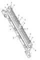
図1は、本発明に係るコネクタ装置の一例を、それに連結された複数の同軸ケーブル、及び、それが嵌合連結される相手方コネクタ装置と共に示す。 FIG. 1 shows an example of a connector device according to the present invention with a plurality of coaxial cables connected thereto and a mating connector device to which it is matedly connected.
図1において、本発明に係るコネクタ装置の一例を成すコネクタ装置11は、複数の同軸ケーブル12が電気的に装着されたもとで、例えば、ソリッド印刷配線基板とされる回路基板(図示が省略されている。)にそれに設けられた電気回路構成部との電気的接続がなされて取り付けられた、相手方コネクタ装置を成す基板側コネクタ装置13に嵌合連結される、ケーブル側コネクタ装置として用いられるものとされている。そして、コネクタ装置11は、合成樹脂等の絶縁材料によって形成された絶縁ハウジング14, 電磁波ノイズ対策のため絶縁ハウジング14に装着された第1のシェル部材15Aと第2のシェル部材15Bとから成る導電性シェル15、及び、導電性シェル15に対して回動可能に配されたカバー付き係合部材16を備えている。 In FIG. 1, a
絶縁ハウジング14には、基板側コネクタ装置13(相手方コネクタ装置)との嵌合状態におかれる板状体を成す嵌合部17が設けられており、また、各々が導電性板状金属材料に屈曲加工が施されて形成された複数のコンタクト18が配列配置されている。導電性シェル15を構成する第1のシェル部材15A及び第2のシェル部材15Bは、各々が弾性を有した金属板材料が屈曲加工されて形成されていて、絶縁ハウジング14を挟み込んで相互係合するものとされており、絶縁ハウジング14にその外面部を部分的に覆う状態をもって固定されている。 The insulating
図2は、導電性シェル15を構成する第1のシェル部材15A及び複数のコンタクト18の夫々の構成、及び、第1のシェル部材15Aと複数のコンタクト18との配置関係を、絶縁ハウジング14を除去した状態をもって示す。図2に示されるように、絶縁ハウジング14に配列配置された複数のコンタクト18の各々は、絶縁ハウジング14の嵌合部17に配される接触接続部19及び同軸ケーブル12が接続されるケーブル接続部20を有しており、複数の接触接続部19が配列されて成る接触接続部列と複数のケーブル接続部20が配列されて成るケーブル接続部列とが、相互に平行なものとして形成されている。複数のコンタクト18の夫々における接触接続部19は折り返し部を成すものとされており、複数のコンタクト18のうちの相互隣接する2個にあっては、接触接続部19が成す折り返し部の折り返し方向が互いに逆方向とされている。そして、第1のシェル部材15Aは、複数のコンタクト18におけるケーブル接続部列側の位置において複数のコンタクト18の配列方向(以下、コンタクト配列方向という。)に沿って伸びる第1のシェル本体部21と、第1のシェル本体部21における長手方向(コンタクト配列方向)の両側端部から夫々突出してコンタクト18に沿う方向に伸びるものとして設けられた一対の突出部22と、第1のシェル本体部21におけるコンタクト配列方向の両端部間の中央部分から突出してコンタクト18に沿う方向に伸びるものとして設けられた突出部23とを有している。そして、第1のシェル本体部21におけるコンタクト配列方向の両端部間の中央部分から突出する突出部23には、透孔24が形成されている。 FIG. 2 shows the configuration of each of the
図3(斜視図),図4(平面図)及び図5(底面図)は、絶縁ハウジング14と図2に示される第1のシェル部材15A及び複数のコンタクト18とが一体形成された状態を示す。図3~図5に示されるように、第1のシェル本体部21におけるコンタクト配列方向の両側端部から夫々突出する一対の突出部22と第1のシェル部材15Aにおける長手方向であるコンタクト配列方向の両端部間の中央部分から突出する突出部23とは、絶縁ハウジング14に設けられて複数のコンタクト18が夫々有する複数の接触接続部19が接触接続部列を成して配された嵌合部17の一部を成すものとされている。そして、一対の突出部22及び突出部23の夫々は、部分的に絶縁ハウジング14の一部に埋め込まれたものとされていて、絶縁ハウジング14に設けられた嵌合部17を補強する役割を果たしている。なお、第1のシェル部材15Aにおけるコンタクト配列方向の両側端部に一対の突出部22が設けられることは必ずしも必要ではなく、突出部23のみが第1のシェル部材15Aにおけるコンタクト配列方向の両端部間の中央部分に設けられる構成がとられてもよい。 3 (perspective view), 4 (top view) and 5 (bottom view) show the state in which the insulating
また、絶縁ハウジング14には、嵌合部17に加えて、コンタクト配列方向に沿って伸びて、配列配置された複数のコンタクト18の夫々における接触接続部19とケーブル接続部20との間の部分を支える竜骨部25が設けられている。絶縁ハウジング14に設けられた竜骨部25は、その内部に複数のコンタクト18の夫々における接触接続部19とケーブル接続部20との間の部分が埋め込まれたものとされており、それとともに、第1のシェル部材15Aが有する突出部23に形成された透孔24を塞ぐものとされている。 In addition to the
このような図3~図5に示される、絶縁ハウジング14と図2に示される第1のシェル部材15A及び複数のコンタクト18とが一体形成されて成る構造体は、例えば、第1のシェル部材15A及び複数のコンタクト18が配置された金型内に、溶融樹脂材が流し込まれて絶縁ハウジング14が形成されるインサート成形によって得られる。斯かるインサート成形が行われるときには、例えば、図4におけるVI-VI線断面を示す図6における第1のシェル部材15Aが有する突出部23に形成された透孔24に対応する位置において、図6に示される矢印Iにより示される方向から金型内に溶融樹脂材が注入され、注入完了後に溶融樹脂材が凝固せしめられて、嵌合部17及び竜骨部25を含めた絶縁ハウジング14が形成される。その結果、絶縁ハウジング14にあっては、図5に示されるように、その底面側に溶融樹脂材の注入部位を示す注入口跡26が残される。 The structure shown in FIGS. 3 to 5, in which the insulating
上述のようにして嵌合部17及び竜骨部25を含めた絶縁ハウジング14を形成するための溶融樹脂材の注入が行われる際には、図2に示される一点鎖線枠E内を拡大して示す図7において複数の矢印によって示されるように、第1のシェル部材15Aが有する突出部23に形成された透孔24が、溶融樹脂材の流路を成すものとされ、それにより、透孔24を塞ぐものとされる絶縁ハウジング14に設けられる竜骨部25における突出部23に対応する部分が、透孔24を通じた溶融樹脂材によって形成される。その結果、突出部23に対応する部分を含めた竜骨部25が、溶融樹脂材が衝突合流することにより生じて脆弱部分となるウエルドラインを伴う虞れなく形成され得ることになる。 When the molten resin material is injected to form the insulating
斯かる際において、仮に、第1のシェル部材15Aが有する突出部23に透孔24が形成されていないとすると、図8において複数の矢印によって示されるように、溶融樹脂材が、第1のシェル部材15Aが有する突出部23のコンタクト配列方向の両側部分側から突出部23を挿み込むようにして流れ込んで衝突合流することになり、それにより、絶縁ハウジング14に設けられる竜骨部25における突出部23に対応する部位に、脆弱部分となるウエルドラインが形成されてしまう虞がある。 In such a case, if the projecting
上述のようにして得られる図3~図5に示される絶縁ハウジング14と第1のシェル部材15Aと複数のコンタクト18とが一体形成されて成る構造体にあっては、複数のコンタクト18のケーブル接続部20に複数の同軸ケーブル12が夫々電気的に接続される(より詳細には、複数の同軸ケーブル12の夫々の中心導体12a(後述される図12及び図13に示されている。)が、複数のコンタクト18のケーブル接続部20のうちの対応するものに接続される。)。それにより、複数の同軸ケーブル12がコネクタ装置11に装着された状態が得られる。また、斯かる構造体における第1のシェル部材15Aに、第1のシェル部材15Aと共に導電性シェル15を構成する第2のシェル部材15Bが係合せしめられて固定され、それにより、図1に示される第1のシェル部材15Aと第2のシェル部材15Bとから成る導電性シェル15が得られる。第2のシェル部材15Bは、複数のコンタクト18におけるケーブル接続部列側の位置においてコンタクト配列方向に沿って伸びる第2のシェル本体部27と、第2のシェル本体部27から突出してコンタクト配列方向に沿って広がり、絶縁ハウジング14に設けられた竜骨部25を覆うものとされた覆い部28とを有している。 In the structure integrally formed of the insulating
第1のシェル部材15Aが有する第1のシェル本体部21と第2のシェル部材15Bが有する第2のシェル本体部27とは、第1のシェル部材15Aに第2のシェル部材15Bが係合せしめられて導電性シェル15を形成するもとにおいて、導電性シェル15におけるコンタクト配列方向に沿って伸びる本体部を成しており、斯かる本体部を有した導電性シェル15は、当該本体部から突出して絶縁ハウジング14に設けられた嵌合部17の一部を成す一対の突出部22と突出部23とを有していることになる。そして、第1のシェル本体部21と第2のシェル本体部27とが成す本体部を有した導電性シェル15は、その本体部が、複数の同軸ケーブル12が接続される複数のコンタクト18が夫々有する複数のケーブル接続部20を覆うものとされて、当該複数のケーブル接続部20に対する電磁遮蔽作用を果たすものとされている。 The first
導電性シェル15に対して回動可能に配されたカバー付き係合部材16は、金属棒材に屈曲加工が施されて形成され、両端部が導電性シェル15の本体部におけるコンタクト配列方向の両端部分に回動自在に係合せしめられた枠状体30と、金属板材に打抜き・屈曲加工が施されて形成され、枠状体30に取り付けられた板状カバー31とを備えている。斯かるカバー付き係合部材16は、コネクタ装置11が基板側コネクタ装置13との嵌合連結状態におかれたとき、板状カバー31によって基板側コネクタ装置13を覆う状態をもって基板側コネクタ装置13に係合し、コネクタ装置11についての基板側コネクタ装置13に対する係止を行い、コネクタ装置11に基板側コネクタ装置13との嵌合連結状態を維持させる役割を果たす。板状カバー31には、基板側コネクタ装置13に当接接触する複数の弾性片部33が設けられている。 The engaging
図1に示される相手方コネクタ装置を成す基板側コネクタ装置13は、図示されていない回路基板に取り付けられたものとされるが、その回路基板における接地電位部に、例えば、半田付けによって接続される複数の基板接続部36が設けられた導電性シェル37と、回路基板に配され、導電性シェル37によって覆われて固定された絶縁ハウジング38とを備えている。絶縁ハウジング38には、コネクタ装置11における絶縁ハウジング14に設けられた嵌合部17が差し込まれて嵌合せしめられる嵌合口部39(後述される図12及び図13に示されている。)が設けられており、嵌合口部39内には複数の基板側コンタクト40(後述される図12及び図13に示されている。)が配列配置されている。 The board-
図9は、コネクタ装置11における絶縁ハウジング14に設けられた嵌合部17が基板側コネクタ装置13の絶縁ハウジング38に設けられた嵌合口部39に差し込まれて、複数の同軸ケーブル12が装着されたコネクタ装置11が基板側コネクタ装置13との嵌合連結状態におかれ、コネクタ装置11に備えられたカバー付き係合部材16が基板側コネクタ装置13に係合した状態を示す。斯かるもとにあっては、コネクタ装置11に備えられたカバー付き係合部材16における板状カバー31が、コネクタ装置11の導電性シェル15を構成する第2のシェル部材15Bにおける覆い部28とコネクタ装置11の絶縁ハウジング14に設けられた嵌合部17が嵌合せしめられた基板側コネクタ装置13と全面的に覆う状態をもって、基板側コネクタ装置13の導電性シェル37に係合するものとされており、板状カバー31に設けられた複数の弾性片部33が、基板側コネクタ装置13の導電性シェル37に当接接触している。 FIG. 9 shows that the
図10及び図11は、図9に示されるように複数の同軸ケーブル12が装着されたコネクタ装置11が基板側コネクタ装置13との嵌合連結状態におかれたもとで、コネクタ装置11に備えられたカバー付き係合部材16が除去された状態を示す。このようにして、コネクタ装置11における絶縁ハウジング14に設けられた嵌合部17が基板側コネクタ装置13の絶縁ハウジング38に設けられた嵌合口部39に差し込まれて、コネクタ装置11が基板側コネクタ装置13との嵌合連結状態におかれたときには、図11における XII-XII 線断面を示す図12及び図11におけるXIII-XIII線断面を示す図13に示されるように、コネクタ装置11における同軸ケーブル12の中心導体12aが接続されたケーブル接続部20を有したコンタクト18の接触接続部19が、コネクタ装置11における嵌合部17に配された状態のもとで、基板側コネクタ装置13における嵌合口部39内に配されて基板側コネクタ装置13が取り付けられた回路基板における電気回路構成部に接続された基板側コンタクト40に接触接続される。それにより、コネクタ装置11に装着された複数の同軸ケーブル12の夫々の中心導体12aが、コネクタ装置11におけるコンタクト18及び基板側コネクタ装置13における基板側コンタクト40を通じて、基板側コネクタ装置13が取り付けられた回路基板における電気回路構成部に電気的に接続される。 10 and 11, the
また、このとき、図11における XIV-XIV 線断面を示す図14に示されるように、コネクタ装置11の絶縁ハウジング14に設けられた嵌合部17の一部を成すものとされた、コネクタ装置11における導電性シェル15の本体部から突出する突出部23は、基板側コネクタ装置13における嵌合口部39内に配されて基板側コネクタ装置13が取り付けられた回路基板における接地電位部に接続された基板側グラウンドコンタクト41に接触接続される。それにより、突出部23が設けられたコネクタ装置11における導電性シェル15に、基板側グラウンドコンタクト41及び突出部23を通じて回路基板における接地電位部からの接地電位が与えられる。 Also, at this time, as shown in FIG. 14 showing the XIV-XIV line cross section in FIG. 11 protruding from the main body of the
上述のようにケーブル側コネクタ装置として用いられるコネクタ装置11にあっては、相手方コネクタ装置とされる基板コネクタ装置13との嵌合状態におかれる板状体を成す嵌合部17が設けられた絶縁ハウジング14と、各々が嵌合部17に配される接触接続部19及び同軸ケーブル12が接続されるケーブル接続部20を有して絶縁ハウジング14に配列配置される複数のコンタクト18と、複数のコンタクト18が夫々有する複数のケーブル接続部20に対する電磁遮蔽作用を果たすものとして絶縁ハウジング14に装着される導電性シェル15とを備えて構成されたもとにおいて、導電性シェル15が有する突出部23が、絶縁ハウジング14に設けられた嵌合部17の一部を成し、部分的に絶縁ハウジング14の一部に埋め込まれたものとされて嵌合部17を補強する役割を果たすので、コネクタ装置11の全体についての低背化が図られて、絶縁ハウジング14に設けられた嵌合部17が薄い肉厚を有した板状体を成すものとされたもとにおいても、当該嵌合部17を剛性が増大せしめられて必要な強度を具えたものとすることができる。その結果、絶縁ハウジング14に設けられた嵌合部17の基板側コネクタ装置13との嵌合に支障が来される事態が回避され、コネクタ装置11の基板側コネクタ装置13に対する嵌合連結が適正に行われることになる。 As described above, the
また、コネクタ装置11においては、導電性シェル15が有する突出部23に透孔24が形成されたものとされて、その透孔24が、絶縁ハウジング14の一部を成す竜骨部25によって塞がれたものとされ、さらには、複数のコンタクト18,導電性シェル15を構成する第1のシェル部材15A及び絶縁ハウジング14についてのインサート成形による一体形成にあたって、絶縁ハウジング14を形成することになる溶融樹脂材の流路を成すものとされるので、複数のコンタクト18,導電性シェル15を構成する第1のシェル部材15A及び絶縁ハウジング14についてのインサート成形による一体形成が、絶縁ハウジング14を形成することになる溶融樹脂材の適正な流れが得られて、例えば、絶縁ハウジング14における不所望なウエルドラインの発生が抑制されるもとで行われ、絶縁ハウジング14に設けられた嵌合部17の強度がさらに高められる。 Further, in the
以上のような本発明に係るコネクタ装置は、絶縁ハウジングと、絶縁ハウジングに装着された導電性シェルと、絶縁ハウジングに配列配置された複数のコンタクトとを備え、絶縁ハウジングが相手方コネクタ装置との嵌合状態におかれる嵌合部が設けられたものとされるとともに、複数のコンタクトの夫々が、絶縁ハウジングに設けられる嵌合部に配される接触接続部及び同軸ケーブルが接続されるケーブル接続部を有していて、嵌合部が相手方コネクタ装置との嵌合状態におかれたとき接触接続部が相手方コネクタ装置における相手方コンタクトに接触接続されるものとされて構成され、全体についての低背化が図られて、絶縁ハウジングに設けられた嵌合部が薄い肉厚を有した板状体を成すものとされたもとにあっても、当該嵌合部を剛性が増大せしめられて必要な強度を具えたものとすることができるものとして、様々な電子機器等に広く適用され得るものである。 The connector device according to the present invention as described above comprises an insulating housing, a conductive shell attached to the insulating housing, and a plurality of contacts arranged in the insulating housing. A contact connection portion in which each of the plurality of contacts is arranged in the fitting portion provided in the insulating housing and a cable connection portion to which the coaxial cable is connected. and when the mating portion is placed in a mated state with the mating connector device, the contact connection portion is contact-connected to the mating contact of the mating connector device, and the overall height is low. Even if the fitting portion provided in the insulating housing is formed into a plate-like body having a thin wall thickness, the rigidity of the fitting portion is increased to achieve the required strength. can be widely applied to various electronic devices.
11・・・コネクタ装置, 12・・・同軸ケーブル, 13・・・基板側コネクタ装置, 14,38・・・絶縁ハウジング, 15,37・・・導電性シェル, 15A・・・第1のシェル部材, 15B・・・第2のシェル部材, 16・・・カバー付き係合部材, 17・・・突出部, 18・・・コンタクト, 19・・・接触接続部, 20・・・ケーブル接続部, 21・・・第1のシェル本体部, 22,23・・・突出部, 24・・・透孔, 25・・・竜骨部, 27・・・第2のシェル本体部, 28・・・覆い部, 30・・・枠状体, 31・・・板状カバー, 33・・・弾性片部, 36・・・基板接続部, 39・・・嵌合口部, 40・・・基板側コンタクト, 41・・・基板側グラウンドコンタクト DESCRIPTION OF
Claims (7)
Translated fromJapanese上記第2方向に沿って並ぶように上記絶縁ハウジングに配列配置され、各々が、
上記嵌合部に配され、上記嵌合部が上記相手方コネクタ装置に差し込まれたとき上記相手方コネクタ装置における相手方コンタクトに接触接続される接触接続部と、
上記第1方向及び上記第2方向に垂直な第3方向から見て上記嵌合部外に配され、同軸ケーブルが接続されるケーブル接続部と、
を有する複数のコンタクトと、
上記複数のコンタクトの複数のケーブル接続部に対する電磁遮蔽作用を果たすものとして上記絶縁ハウジングに装着される導電性シェルと、
を備えて構成され、
上記導電性シェルは、
上記嵌合部外において、上記第3方向にて上記複数のケーブル接続部と対向するとともに、上記第2方向に沿って伸びる本体部と、
上記嵌合部において、上記複数のコンタクトの複数の接触接続部と上記第2方向に沿って並ぶように、上記本体部から突出して部分的に上記嵌合部に埋め込まれ、上記嵌合部と共に上記第1方向に沿って上記相手方コネクタ装置に差し込まれる突出部と、
を有し、
上記突出部が、上記導電性シェルが有する上記本体部における上記複数のコンタクトの配列方向の両端部間の中央部分から突出していることを特徴とするコネクタ装置。an insulating housing that spreads in a plate shape along first and second directions perpendicular to each other and has a fitting portion that is inserted into the mating connector device along the first direction;
arranged in the insulating housing so as to be aligned along the second direction, each
a contact connection portion arranged in the mating portion and contact-connected to the mating contact of the mating connector device when the mating portion is inserted into the mating connector device;
a cable connection portion arranged outside the fitting portion when viewed from a third direction perpendicular to the first direction and the second direction, and to which a coaxial cable is connected;
a plurality of contacts having
a conductive shell mounted on the insulating housing to provide electromagnetic shielding for the cable connections of the contacts;
configured with
The conductive shell is
a body portion outside the fitting portion facing the plurality of cable connection portions in the third direction and extending along the second direction;
In the fitting portion, the contact connection portion protrudes from the body portion and is partially embedded in the fitting portion so as to be aligned with the plurality of contact connection portions of the plurality of contacts along the second direction. a protrusion that is inserted into the mating connectordevice along the first direction;
has
A connector device according to claim 1, whereinthe protruding portion protrudes from a central portion between both end portions in the arrangement direction of the plurality of contacts in the body portion of the conductive shell .
上記第2方向に沿って並ぶように上記絶縁ハウジングに配列配置され、各々が、 arranged in the insulating housing so as to be aligned along the second direction, each
上記嵌合部に配され、上記嵌合部が上記相手方コネクタ装置に差し込まれたとき上記相手方コネクタ装置における相手方コンタクトに接触接続される接触接続部と、 a contact connection portion arranged in the mating portion and contact-connected to the mating contact of the mating connector device when the mating portion is inserted into the mating connector device;
上記第1方向及び上記第2方向に垂直な第3方向から見て上記嵌合部外に配され、同軸ケーブルが接続されるケーブル接続部と、 a cable connection portion arranged outside the fitting portion when viewed from a third direction perpendicular to the first direction and the second direction, and to which a coaxial cable is connected;
を有する複数のコンタクトと、a plurality of contacts having
上記複数のコンタクトの複数のケーブル接続部に対する電磁遮蔽作用を果たすものとして上記絶縁ハウジングに装着される導電性シェルと、 a conductive shell mounted on the insulating housing to provide electromagnetic shielding for the cable connections of the contacts;
を備えて構成され、configured with
上記導電性シェルは、 The conductive shell is
上記嵌合部外において、上記第3方向にて上記複数のケーブル接続部と対向するとともに、上記第2方向に沿って伸びる本体部と、 a body portion outside the fitting portion facing the plurality of cable connection portions in the third direction and extending along the second direction;
上記嵌合部において、上記複数のコンタクトの複数の接触接続部と上記第2方向に沿って並ぶように、上記本体部から突出して部分的に上記嵌合部に埋め込まれ、上記嵌合部と共に上記第1方向に沿って上記相手方コネクタ装置に差し込まれる突出部と、 In the fitting portion, the contact connection portion protrudes from the body portion and is partially embedded in the fitting portion so as to be aligned with the plurality of contact connection portions of the plurality of contacts along the second direction. a protrusion that is inserted into the mating connector device along the first direction;
を有し、has
上記導電性シェルが、上記絶縁ハウジングを挟んで相互対向する第1のシェル部材と第2のシェル部材とを含んで成り、上記突出部が、上記第1のシェル部材及び上記第2のシェル部材のうちの一方から突出することを特徴とするコネクタ装置。 The conductive shell comprises a first shell member and a second shell member facing each other with the insulating housing interposed therebetween, and the projecting portion comprises the first shell member and the second shell member. A connector device, characterized in that it protrudes from one of:
Priority Applications (1)
| Application Number | Priority Date | Filing Date | Title |
|---|---|---|---|
| JP2018039337AJP7196402B2 (en) | 2018-03-06 | 2018-03-06 | connector device |
Applications Claiming Priority (1)
| Application Number | Priority Date | Filing Date | Title |
|---|---|---|---|
| JP2018039337AJP7196402B2 (en) | 2018-03-06 | 2018-03-06 | connector device |
Publications (2)
| Publication Number | Publication Date |
|---|---|
| JP2019153528A JP2019153528A (en) | 2019-09-12 |
| JP7196402B2true JP7196402B2 (en) | 2022-12-27 |
Family
ID=67946871
Family Applications (1)
| Application Number | Title | Priority Date | Filing Date |
|---|---|---|---|
| JP2018039337AActiveJP7196402B2 (en) | 2018-03-06 | 2018-03-06 | connector device |
Country Status (1)
| Country | Link |
|---|---|
| JP (1) | JP7196402B2 (en) |
Citations (4)
| Publication number | Priority date | Publication date | Assignee | Title |
|---|---|---|---|---|
| JP2008097875A (en) | 2006-10-06 | 2008-04-24 | Three M Innovative Properties Co | Connector assembly |
| JP2009032517A (en) | 2007-07-26 | 2009-02-12 | Japan Aviation Electronics Industry Ltd | Connector and electronic device having the same |
| JP2011165357A (en) | 2010-02-05 | 2011-08-25 | I-Pex Co Ltd | Connector apparatus |
| JP2012014906A (en) | 2010-06-30 | 2012-01-19 | Japan Aviation Electronics Industry Ltd | Connector |
- 2018
- 2018-03-06JPJP2018039337Apatent/JP7196402B2/enactiveActive
Patent Citations (4)
| Publication number | Priority date | Publication date | Assignee | Title |
|---|---|---|---|---|
| JP2008097875A (en) | 2006-10-06 | 2008-04-24 | Three M Innovative Properties Co | Connector assembly |
| JP2009032517A (en) | 2007-07-26 | 2009-02-12 | Japan Aviation Electronics Industry Ltd | Connector and electronic device having the same |
| JP2011165357A (en) | 2010-02-05 | 2011-08-25 | I-Pex Co Ltd | Connector apparatus |
| JP2012014906A (en) | 2010-06-30 | 2012-01-19 | Japan Aviation Electronics Industry Ltd | Connector |
Also Published As
| Publication number | Publication date |
|---|---|
| JP2019153528A (en) | 2019-09-12 |
Similar Documents
| Publication | Publication Date | Title |
|---|---|---|
| JP7281537B2 (en) | connector | |
| KR101471283B1 (en) | Electrical connector for use with a circuit board | |
| US11444414B2 (en) | Connector and connector device | |
| JP2025108789A (en) | connector | |
| JP4618745B1 (en) | Electrical connector | |
| US8317543B2 (en) | Electrical connector | |
| CN110299635A (en) | Connector and electronic equipment | |
| CN102882032A (en) | Terminal and connector having the same | |
| CN117546374A (en) | Connector for substrate and machine | |
| CN102195185A (en) | Electric connector and manufacture method thereof | |
| KR101549339B1 (en) | Plug connector and method of manufacturing the same | |
| JP4803761B2 (en) | Connector device | |
| JP2008097875A (en) | Connector assembly | |
| JPWO2008001453A1 (en) | Connector for coaxial cable | |
| EP3832809A1 (en) | Cable connector | |
| CN117616646A (en) | Connectors and machines for circuit boards | |
| JP5344239B2 (en) | Board shield connector | |
| JP5787081B2 (en) | Connector device | |
| JP7353123B2 (en) | Connectors and connector assemblies | |
| JP2002033161A (en) | Connection structure of board shield connector | |
| JP7196402B2 (en) | connector device | |
| JP5549072B2 (en) | Circuit board built-in connector | |
| KR20110082543A (en) | Board Cable Junction | |
| JP5473638B2 (en) | Electrical connector | |
| JP7640770B2 (en) | Connector set and connector |
Legal Events
| Date | Code | Title | Description |
|---|---|---|---|
| A521 | Request for written amendment filed | Free format text:JAPANESE INTERMEDIATE CODE: A523 Effective date:20180920 | |
| RD03 | Notification of appointment of power of attorney | Free format text:JAPANESE INTERMEDIATE CODE: A7423 Effective date:20190823 | |
| RD04 | Notification of resignation of power of attorney | Free format text:JAPANESE INTERMEDIATE CODE: A7424 Effective date:20190902 | |
| A621 | Written request for application examination | Free format text:JAPANESE INTERMEDIATE CODE: A621 Effective date:20210128 | |
| A977 | Report on retrieval | Free format text:JAPANESE INTERMEDIATE CODE: A971007 Effective date:20211119 | |
| A131 | Notification of reasons for refusal | Free format text:JAPANESE INTERMEDIATE CODE: A131 Effective date:20211124 | |
| A521 | Request for written amendment filed | Free format text:JAPANESE INTERMEDIATE CODE: A523 Effective date:20220124 | |
| A131 | Notification of reasons for refusal | Free format text:JAPANESE INTERMEDIATE CODE: A131 Effective date:20220531 | |
| A521 | Request for written amendment filed | Free format text:JAPANESE INTERMEDIATE CODE: A523 Effective date:20220726 | |
| TRDD | Decision of grant or rejection written | ||
| A01 | Written decision to grant a patent or to grant a registration (utility model) | Free format text:JAPANESE INTERMEDIATE CODE: A01 Effective date:20221115 | |
| A61 | First payment of annual fees (during grant procedure) | Free format text:JAPANESE INTERMEDIATE CODE: A61 Effective date:20221128 | |
| R150 | Certificate of patent or registration of utility model | Ref document number:7196402 Country of ref document:JP Free format text:JAPANESE INTERMEDIATE CODE: R150 |