JP7194677B2 - Non-combustible smoking device and elements thereof - Google Patents
Non-combustible smoking device and elements thereofDownload PDFInfo
- Publication number
- JP7194677B2 JP7194677B2JP2019518276AJP2019518276AJP7194677B2JP 7194677 B2JP7194677 B2JP 7194677B2JP 2019518276 AJP2019518276 AJP 2019518276AJP 2019518276 AJP2019518276 AJP 2019518276AJP 7194677 B2JP7194677 B2JP 7194677B2
- Authority
- JP
- Japan
- Prior art keywords
- tobacco
- vapor
- combustible smoking
- heater
- housing
- Prior art date
- Legal status (The legal status is an assumption and is not a legal conclusion. Google has not performed a legal analysis and makes no representation as to the accuracy of the status listed.)
- Active
Links
- 230000000391smoking effectEffects0.000titleclaimsdescription134
- 235000002637Nicotiana tabacumNutrition0.000claimsdescription298
- 241000208125NicotianaSpecies0.000claimsdescription297
- 238000009472formulationMethods0.000claimsdescription150
- 239000000203mixtureSubstances0.000claimsdescription150
- 239000000463materialSubstances0.000claimsdescription57
- 238000005192partitionMethods0.000claimsdescription35
- 238000010438heat treatmentMethods0.000claimsdescription15
- 229910052751metalInorganic materials0.000claimsdescription11
- 239000002184metalSubstances0.000claimsdescription11
- 239000004696Poly ether ether ketoneSubstances0.000claimsdescription10
- 229920002530polyetherether ketonePolymers0.000claimsdescription10
- 239000003570airSubstances0.000description103
- 235000019504cigarettesNutrition0.000description19
- 238000003860storageMethods0.000description15
- 235000019506cigarNutrition0.000description11
- 229920002301cellulose acetatePolymers0.000description10
- 239000000919ceramicSubstances0.000description9
- -1polyethylene terephthalatePolymers0.000description8
- 239000010935stainless steelSubstances0.000description8
- 229910001220stainless steelInorganic materials0.000description8
- 229910052782aluminiumInorganic materials0.000description7
- XAGFODPZIPBFFR-UHFFFAOYSA-NaluminiumChemical compound[Al]XAGFODPZIPBFFR-UHFFFAOYSA-N0.000description7
- 238000011144upstream manufacturingMethods0.000description7
- 230000009471actionEffects0.000description6
- URAYPUMNDPQOKB-UHFFFAOYSA-NtriacetinChemical compoundCC(=O)OCC(OC(C)=O)COC(C)=OURAYPUMNDPQOKB-UHFFFAOYSA-N0.000description6
- 230000008016vaporizationEffects0.000description6
- PXHVJJICTQNCMI-UHFFFAOYSA-NNickelChemical compound[Ni]PXHVJJICTQNCMI-UHFFFAOYSA-N0.000description5
- 229910045601alloyInorganic materials0.000description4
- 239000000956alloySubstances0.000description4
- 238000001816coolingMethods0.000description4
- 239000000835fiberSubstances0.000description4
- 150000002739metalsChemical class0.000description4
- SNICXCGAKADSCV-JTQLQIEISA-N(-)-NicotineChemical compoundCN1CCC[C@H]1C1=CC=CN=C1SNICXCGAKADSCV-JTQLQIEISA-N0.000description3
- XEEYBQQBJWHFJM-UHFFFAOYSA-NIronChemical compound[Fe]XEEYBQQBJWHFJM-UHFFFAOYSA-N0.000description3
- 239000004698PolyethyleneSubstances0.000description3
- 239000004743PolypropyleneSubstances0.000description3
- DNIAPMSPPWPWGF-UHFFFAOYSA-NPropylene glycolChemical compoundCC(O)CODNIAPMSPPWPWGF-UHFFFAOYSA-N0.000description3
- 230000008901benefitEffects0.000description3
- 238000009835boilingMethods0.000description3
- 239000002131composite materialSubstances0.000description3
- 239000004020conductorSubstances0.000description3
- 230000007423decreaseEffects0.000description3
- 230000000694effectsEffects0.000description3
- 239000011888foilSubstances0.000description3
- 239000011521glassSubstances0.000description3
- 239000001087glyceryl triacetateSubstances0.000description3
- 235000013773glyceryl triacetateNutrition0.000description3
- 238000003780insertionMethods0.000description3
- 230000037431insertionEffects0.000description3
- 229910021326iron aluminideInorganic materials0.000description3
- 238000012986modificationMethods0.000description3
- 230000004048modificationEffects0.000description3
- 229960002715nicotineDrugs0.000description3
- SNICXCGAKADSCV-UHFFFAOYSA-NnicotineNatural productsCN1CCCC1C1=CC=CN=C1SNICXCGAKADSCV-UHFFFAOYSA-N0.000description3
- 229920003023plasticPolymers0.000description3
- 239000004033plasticSubstances0.000description3
- BASFCYQUMIYNBI-UHFFFAOYSA-NplatinumChemical group[Pt]BASFCYQUMIYNBI-UHFFFAOYSA-N0.000description3
- 229920000573polyethylenePolymers0.000description3
- 229920001155polypropylenePolymers0.000description3
- 238000012546transferMethods0.000description3
- 229960002622triacetinDrugs0.000description3
- 239000012808vapor phaseSubstances0.000description3
- LFQSCWFLJHTTHZ-UHFFFAOYSA-NEthanolChemical compoundCCOLFQSCWFLJHTTHZ-UHFFFAOYSA-N0.000description2
- 229910015372FeAlInorganic materials0.000description2
- PEDCQBHIVMGVHV-UHFFFAOYSA-NGlycerineChemical compoundOCC(O)COPEDCQBHIVMGVHV-UHFFFAOYSA-N0.000description2
- HBBGRARXTFLTSG-UHFFFAOYSA-NLithium ionChemical compound[Li+]HBBGRARXTFLTSG-UHFFFAOYSA-N0.000description2
- NPXOKRUENSOPAO-UHFFFAOYSA-NRaney nickelChemical compound[Al].[Ni]NPXOKRUENSOPAO-UHFFFAOYSA-N0.000description2
- RTAQQCXQSZGOHL-UHFFFAOYSA-NTitaniumChemical compound[Ti]RTAQQCXQSZGOHL-UHFFFAOYSA-N0.000description2
- QCWXUUIWCKQGHC-UHFFFAOYSA-NZirconiumChemical compound[Zr]QCWXUUIWCKQGHC-UHFFFAOYSA-N0.000description2
- UJXVAJQDLVNWPS-UHFFFAOYSA-N[Al].[Al].[Al].[Fe]Chemical compound[Al].[Al].[Al].[Fe]UJXVAJQDLVNWPS-UHFFFAOYSA-N0.000description2
- 230000004913activationEffects0.000description2
- PNEYBMLMFCGWSK-UHFFFAOYSA-Naluminium oxideInorganic materials[O-2].[O-2].[O-2].[Al+3].[Al+3]PNEYBMLMFCGWSK-UHFFFAOYSA-N0.000description2
- QVGXLLKOCUKJST-UHFFFAOYSA-Natomic oxygenChemical compound[O]QVGXLLKOCUKJST-UHFFFAOYSA-N0.000description2
- 239000011324beadSubstances0.000description2
- 239000000788chromium alloySubstances0.000description2
- GUTLYIVDDKVIGB-UHFFFAOYSA-Ncobalt atomChemical compound[Co]GUTLYIVDDKVIGB-UHFFFAOYSA-N0.000description2
- 238000004891communicationMethods0.000description2
- 238000009833condensationMethods0.000description2
- 230000005494condensationEffects0.000description2
- 235000013305foodNutrition0.000description2
- 239000004615ingredientSubstances0.000description2
- 229910001416lithium ionInorganic materials0.000description2
- 238000004519manufacturing processMethods0.000description2
- 229910052759nickelInorganic materials0.000description2
- 229910000907nickel aluminideInorganic materials0.000description2
- 229910000623nickel–chromium alloyInorganic materials0.000description2
- 229910052760oxygenInorganic materials0.000description2
- 239000001301oxygenSubstances0.000description2
- 229920000642polymerPolymers0.000description2
- 229920001296polysiloxanePolymers0.000description2
- 239000000843powderSubstances0.000description2
- 230000000717retained effectEffects0.000description2
- 239000007787solidSubstances0.000description2
- 229910000601superalloyInorganic materials0.000description2
- 229910052715tantalumInorganic materials0.000description2
- GUVRBAGPIYLISA-UHFFFAOYSA-Ntantalum atomChemical compound[Ta]GUVRBAGPIYLISA-UHFFFAOYSA-N0.000description2
- 229920005992thermoplastic resinPolymers0.000description2
- 229910052719titaniumInorganic materials0.000description2
- 239000010936titaniumSubstances0.000description2
- 229910052726zirconiumInorganic materials0.000description2
- YPFNIPKMNMDDDB-UHFFFAOYSA-K2-[2-[bis(carboxylatomethyl)amino]ethyl-(2-hydroxyethyl)amino]acetate;iron(3+)Chemical compound[Fe+3].OCCN(CC([O-])=O)CCN(CC([O-])=O)CC([O-])=OYPFNIPKMNMDDDB-UHFFFAOYSA-K0.000description1
- OKTJSMMVPCPJKN-UHFFFAOYSA-NCarbonChemical compound[C]OKTJSMMVPCPJKN-UHFFFAOYSA-N0.000description1
- VYZAMTAEIAYCRO-UHFFFAOYSA-NChromiumChemical compound[Cr]VYZAMTAEIAYCRO-UHFFFAOYSA-N0.000description1
- RYGMFSIKBFXOCR-UHFFFAOYSA-NCopperChemical compound[Cu]RYGMFSIKBFXOCR-UHFFFAOYSA-N0.000description1
- 229920000742CottonPolymers0.000description1
- 229910000599Cr alloyInorganic materials0.000description1
- 229910000881Cu alloyInorganic materials0.000description1
- 239000004606Fillers/ExtendersSubstances0.000description1
- GYHNNYVSQQEPJS-UHFFFAOYSA-NGalliumChemical compound[Ga]GYHNNYVSQQEPJS-UHFFFAOYSA-N0.000description1
- PWHULOQIROXLJO-UHFFFAOYSA-NManganeseChemical compound[Mn]PWHULOQIROXLJO-UHFFFAOYSA-N0.000description1
- ZOKXTWBITQBERF-UHFFFAOYSA-NMolybdenumChemical compound[Mo]ZOKXTWBITQBERF-UHFFFAOYSA-N0.000description1
- 244000061176Nicotiana tabacumSpecies0.000description1
- 229920000297RayonPolymers0.000description1
- ATJFFYVFTNAWJD-UHFFFAOYSA-NTinChemical compound[Sn]ATJFFYVFTNAWJD-UHFFFAOYSA-N0.000description1
- KLARSDUHONHPRF-UHFFFAOYSA-N[Li].[Mn]Chemical compound[Li].[Mn]KLARSDUHONHPRF-UHFFFAOYSA-N0.000description1
- 239000004480active ingredientSubstances0.000description1
- WYTGDNHDOZPMIW-RCBQFDQVSA-NalstonineNatural productsC1=CC2=C3C=CC=CC3=NC2=C2N1C[C@H]1[C@H](C)OC=C(C(=O)OC)[C@H]1C2WYTGDNHDOZPMIW-RCBQFDQVSA-N0.000description1
- 239000012080ambient airSubstances0.000description1
- 239000007961artificial flavoring substanceSubstances0.000description1
- OJIJEKBXJYRIBZ-UHFFFAOYSA-Ncadmium nickelChemical compound[Ni].[Cd]OJIJEKBXJYRIBZ-UHFFFAOYSA-N0.000description1
- 229910010293ceramic materialInorganic materials0.000description1
- 238000006243chemical reactionMethods0.000description1
- 229910052804chromiumInorganic materials0.000description1
- 239000011651chromiumSubstances0.000description1
- UPHIPHFJVNKLMR-UHFFFAOYSA-Nchromium ironChemical compound[Cr].[Fe]UPHIPHFJVNKLMR-UHFFFAOYSA-N0.000description1
- 230000003749cleanlinessEffects0.000description1
- 239000003245coalSubstances0.000description1
- 239000010941cobaltSubstances0.000description1
- 229910017052cobaltInorganic materials0.000description1
- CKFRRHLHAJZIIN-UHFFFAOYSA-Ncobalt lithiumChemical compound[Li].[Co]CKFRRHLHAJZIIN-UHFFFAOYSA-N0.000description1
- 150000001875compoundsChemical class0.000description1
- 229910052802copperInorganic materials0.000description1
- 239000010949copperSubstances0.000description1
- 238000012864cross contaminationMethods0.000description1
- 230000006866deteriorationEffects0.000description1
- 239000000284extractSubstances0.000description1
- 239000011152fibreglassSubstances0.000description1
- 239000002657fibrous materialSubstances0.000description1
- 239000000796flavoring agentSubstances0.000description1
- 235000019634flavorsNutrition0.000description1
- 239000012530fluidSubstances0.000description1
- 239000000446fuelSubstances0.000description1
- 229910052733galliumInorganic materials0.000description1
- 239000003365glass fiberSubstances0.000description1
- 235000011187glycerolNutrition0.000description1
- 229910002804graphiteInorganic materials0.000description1
- 239000010439graphiteSubstances0.000description1
- 229910052735hafniumInorganic materials0.000description1
- VBJZVLUMGGDVMO-UHFFFAOYSA-Nhafnium atomChemical compound[Hf]VBJZVLUMGGDVMO-UHFFFAOYSA-N0.000description1
- 229920001903high density polyethylenePolymers0.000description1
- 239000004700high-density polyethyleneSubstances0.000description1
- 239000011810insulating materialSubstances0.000description1
- 229910052742ironInorganic materials0.000description1
- 229920001684low density polyethylenePolymers0.000description1
- 239000004702low-density polyethyleneSubstances0.000description1
- 229910052748manganeseInorganic materials0.000description1
- 239000011572manganeseSubstances0.000description1
- 238000005297material degradation processMethods0.000description1
- 230000007246mechanismEffects0.000description1
- 229910052987metal hydrideInorganic materials0.000description1
- 238000000034methodMethods0.000description1
- 229910052750molybdenumInorganic materials0.000description1
- 239000011733molybdenumSubstances0.000description1
- 229910052758niobiumInorganic materials0.000description1
- 239000010955niobiumSubstances0.000description1
- GUCVJGMIXFAOAE-UHFFFAOYSA-Nniobium atomChemical compound[Nb]GUCVJGMIXFAOAE-UHFFFAOYSA-N0.000description1
- 238000013021overheatingMethods0.000description1
- 230000000704physical effectEffects0.000description1
- 229910052697platinumInorganic materials0.000description1
- 229920000728polyesterPolymers0.000description1
- 229920000139polyethylene terephthalatePolymers0.000description1
- 239000005020polyethylene terephthalateSubstances0.000description1
- 239000004800polyvinyl chlorideSubstances0.000description1
- 229920000915polyvinyl chloridePolymers0.000description1
- 239000011148porous materialSubstances0.000description1
- 239000002964rayonSubstances0.000description1
- 230000009467reductionEffects0.000description1
- 238000004904shorteningMethods0.000description1
- 239000002002slurrySubstances0.000description1
- 239000007779soft materialSubstances0.000description1
- 239000002904solventSubstances0.000description1
- 239000000126substanceSubstances0.000description1
- 229920002994synthetic fiberPolymers0.000description1
- 239000012209synthetic fiberSubstances0.000description1
- WFKWXMTUELFFGS-UHFFFAOYSA-NtungstenChemical compound[W]WFKWXMTUELFFGS-UHFFFAOYSA-N0.000description1
- 229910052721tungstenInorganic materials0.000description1
- 239000010937tungstenSubstances0.000description1
- 238000009834vaporizationMethods0.000description1
- 238000009423ventilationMethods0.000description1
- 238000010792warmingMethods0.000description1
- XLYOFNOQVPJJNP-UHFFFAOYSA-NwaterSubstancesOXLYOFNOQVPJJNP-UHFFFAOYSA-N0.000description1
Images


Classifications
- A—HUMAN NECESSITIES
- A24—TOBACCO; CIGARS; CIGARETTES; SIMULATED SMOKING DEVICES; SMOKERS' REQUISITES
- A24F—SMOKERS' REQUISITES; MATCH BOXES; SIMULATED SMOKING DEVICES
- A24F40/00—Electrically operated smoking devices; Component parts thereof; Manufacture thereof; Maintenance or testing thereof; Charging means specially adapted therefor
- A24F40/40—Constructional details, e.g. connection of cartridges and battery parts
- A24F40/42—Cartridges or containers for inhalable precursors
- A—HUMAN NECESSITIES
- A24—TOBACCO; CIGARS; CIGARETTES; SIMULATED SMOKING DEVICES; SMOKERS' REQUISITES
- A24F—SMOKERS' REQUISITES; MATCH BOXES; SIMULATED SMOKING DEVICES
- A24F40/00—Electrically operated smoking devices; Component parts thereof; Manufacture thereof; Maintenance or testing thereof; Charging means specially adapted therefor
- A24F40/30—Devices using two or more structurally separated inhalable precursors, e.g. using two liquid precursors in two cartridges
- A—HUMAN NECESSITIES
- A24—TOBACCO; CIGARS; CIGARETTES; SIMULATED SMOKING DEVICES; SMOKERS' REQUISITES
- A24F—SMOKERS' REQUISITES; MATCH BOXES; SIMULATED SMOKING DEVICES
- A24F40/00—Electrically operated smoking devices; Component parts thereof; Manufacture thereof; Maintenance or testing thereof; Charging means specially adapted therefor
- A24F40/40—Constructional details, e.g. connection of cartridges and battery parts
- A24F40/46—Shape or structure of electric heating means
- A—HUMAN NECESSITIES
- A24—TOBACCO; CIGARS; CIGARETTES; SIMULATED SMOKING DEVICES; SMOKERS' REQUISITES
- A24F—SMOKERS' REQUISITES; MATCH BOXES; SIMULATED SMOKING DEVICES
- A24F40/00—Electrically operated smoking devices; Component parts thereof; Manufacture thereof; Maintenance or testing thereof; Charging means specially adapted therefor
- A24F40/40—Constructional details, e.g. connection of cartridges and battery parts
- A24F40/48—Fluid transfer means, e.g. pumps
- A24F40/485—Valves; Apertures
- A—HUMAN NECESSITIES
- A24—TOBACCO; CIGARS; CIGARETTES; SIMULATED SMOKING DEVICES; SMOKERS' REQUISITES
- A24F—SMOKERS' REQUISITES; MATCH BOXES; SIMULATED SMOKING DEVICES
- A24F40/00—Electrically operated smoking devices; Component parts thereof; Manufacture thereof; Maintenance or testing thereof; Charging means specially adapted therefor
- A24F40/50—Control or monitoring
- A24F40/51—Arrangement of sensors
- A—HUMAN NECESSITIES
- A24—TOBACCO; CIGARS; CIGARETTES; SIMULATED SMOKING DEVICES; SMOKERS' REQUISITES
- A24F—SMOKERS' REQUISITES; MATCH BOXES; SIMULATED SMOKING DEVICES
- A24F40/00—Electrically operated smoking devices; Component parts thereof; Manufacture thereof; Maintenance or testing thereof; Charging means specially adapted therefor
- A24F40/50—Control or monitoring
- A24F40/57—Temperature control
- A—HUMAN NECESSITIES
- A24—TOBACCO; CIGARS; CIGARETTES; SIMULATED SMOKING DEVICES; SMOKERS' REQUISITES
- A24F—SMOKERS' REQUISITES; MATCH BOXES; SIMULATED SMOKING DEVICES
- A24F40/00—Electrically operated smoking devices; Component parts thereof; Manufacture thereof; Maintenance or testing thereof; Charging means specially adapted therefor
- A24F40/10—Devices using liquid inhalable precursors
- A—HUMAN NECESSITIES
- A24—TOBACCO; CIGARS; CIGARETTES; SIMULATED SMOKING DEVICES; SMOKERS' REQUISITES
- A24F—SMOKERS' REQUISITES; MATCH BOXES; SIMULATED SMOKING DEVICES
- A24F40/00—Electrically operated smoking devices; Component parts thereof; Manufacture thereof; Maintenance or testing thereof; Charging means specially adapted therefor
- A24F40/20—Devices using solid inhalable precursors
Description
Translated fromJapanese少なくともいくつかの例示的な実施形態は、一般的に、不燃性喫煙装置に関連する。 At least some exemplary embodiments relate generally to non-combustible smoking devices.
電子ベイピング装置は、プレベイパー製剤をベイパー(蒸気)へと気化させるために使用される。これらの電子ベイピング装置は、eベイピング装置と呼ばれる場合がある。eベイピング装置は、プレベイパー製剤を気化させてベイパーを生成するヒーターを含む。eベイピング装置は、電源と、カートリッジまたはヒーターを含むeベイピングタンクと、プレベイパー製剤を保持できる貯蔵部とを含む幾つかのeベイピング要素を含んでもよい。 Electronic vaping devices are used to vaporize pre-vapor formulations into vapors. These electronic vaping devices are sometimes referred to as e-vaping devices. The e-vaping device includes a heater that vaporizes the pre-vapor formulation to produce the vapor. An e-vaping device may include several e-vaping elements including a power source, an e-vaping tank containing a cartridge or heater, and a reservoir capable of holding a pre-vapor formulation.
少なくとも一つの例示的な実施形態は、不燃性喫煙装置に関連する。不燃性喫煙装置は、プレベイパー製剤を加熱するヒーターを有してもよく、発生したベイパーを受けるたばこ要素に熱を提供しうる。より詳細には、例示的な実施形態による不燃性喫煙装置は、発生したベイパーをたばこ要素に晒し、プレベイパー製剤をたばこ要素に晒し、またはその両方を行う。 At least one exemplary embodiment relates to a non-combustible smoking device. The non-combustible smoking device may have a heater that heats the pre-vapor formulation and may provide heat to the tobacco element that receives the generated vapor. More specifically, non-combustible smoking devices according to exemplary embodiments expose generated vapor to tobacco elements, pre-vapor formulations to tobacco elements, or both.
少なくとも一つの例示的な実施形態は、プレベイパー製剤材料を収容するように構成されるプレベイパー製剤貯蔵部と、プレベイパー製剤貯蔵部に結合され、プレベイパー製剤材料の少なくとも一部分を加熱して、発生したベイパーにし、発生したベイパーをチャネルの第一の部分に提供するように構成される発熱体と、チャネルの第二の部分にあり、発生したベイパーを受けるように位置付けられるたばこハウジングであって、たばこを含む、たばこハウジングと、発生したベイパーの少なくとも第一の部分を不燃性喫煙要素の端部に向けて方向付けるためのたばこハウジング内の少なくとも一つの気流要素と、を含む不燃性喫煙要素を開示する。 At least one exemplary embodiment includes a pre-vapor formulation reservoir configured to contain a pre-vapor formulation material and coupled to the pre-vapor formulation reservoir to heat at least a portion of the pre-vapor formulation material into the generated vapor. a heating element configured to provide generated vapor to a first portion of the channel; and a tobacco housing in a second portion of the channel and positioned to receive the generated vapor, the housing comprising tobacco. , a non-combustible smoking element including a tobacco housing and at least one airflow element within the tobacco housing for directing at least a first portion of generated vapor toward an end of the non-combustible smoking element.
例示的な実施形態では、気流要素は、たばこハウジングの第一の端部分からたばこハウジングの対向する第二の端部分まで延在する。 In an exemplary embodiment, the airflow element extends from a first end portion of the tobacco housing to an opposing second end portion of the tobacco housing.
例示的な実施形態では、気流要素は、たばこハウジングを第一の部分と第二の部分に分離し、第一の部分は、発生したベイパーの第一の部分がたばこに晒されることを防ぐように構成される。 In an exemplary embodiment, the airflow element separates the tobacco housing into a first portion and a second portion, the first portion preventing exposure of the first portion of generated vapor to the tobacco. configured to
例示的な実施形態では、発生したベイパーの第一の部分は、発生したベイパーの全体の約65パーセントである。 In an exemplary embodiment, the first portion of vapor generated is about 65 percent of the total vapor generated.
例示的な実施形態では、気流要素は管である。 In an exemplary embodiment, the airflow element is a tube.
例示的な実施形態において、管は0.5ミリメートル~3ミリメートルの内径を有する。 In an exemplary embodiment, the tube has an inner diameter of 0.5 millimeters to 3 millimeters.
例示的な実施形態において、管は2ミリメートル~2.5ミリメートルの内径を有する。 In an exemplary embodiment, the tube has an inner diameter of 2 millimeters to 2.5 millimeters.
例示的な実施形態では、気流要素は、たばこハウジングを二つのセクションに区分する。 In an exemplary embodiment, the airflow element divides the tobacco housing into two sections.
例示的な実施形態では、気流要素は、PEEKおよび金属のうちの少なくとも一つを含む。 In an exemplary embodiment, the airflow element includes at least one of PEEK and metal.
少なくとも一つの例示的な実施形態は、プレベイパー製剤材料を収容するように構成されるプレベイパー製剤貯蔵部と、プレベイパー製剤貯蔵部に結合され、プレベイパー製剤材料の少なくとも一部分を加熱して、発生したベイパーにし、発生したベイパーをチャネルの第一の部分に提供するように構成される発熱体と、チャネルの第二の部分に延在する仕切りであって、仕切りが、長軸方向に延在し、チャネルの第二の部分を単一の空気流路部分とたばこ部分に区分し、単一の空気流路部分およびたばこ部分が、発生したベイパーを受けるように位置付けられ、たばこ部分が、たばこを有し、発生したベイパーの第一の部分を受けるように位置付けられる、たばこ部分を含む、仕切りと、を含む、不燃性喫煙要素を開示する。 At least one exemplary embodiment includes a pre-vapor formulation reservoir configured to contain a pre-vapor formulation material and coupled to the pre-vapor formulation reservoir to heat at least a portion of the pre-vapor formulation material into the generated vapor. a heating element configured to provide generated vapor to a first portion of the channel; and a partition extending to a second portion of the channel, the partition extending longitudinally to the channel. subdividing a second portion of the air channel portion into a single air channel portion and a tobacco portion, the single air channel portion and the tobacco portion positioned to receive the generated vapor, the tobacco portion having tobacco; and a partition including a tobacco portion positioned to receive a first portion of generated vapor.
例示的な実施形態では、仕切りは、金属を含み、発熱体により生成された熱を伝導して、たばこを加熱するように構成される。 In an exemplary embodiment, the partition comprises metal and is configured to conduct heat generated by the heating element to heat the tobacco.
例示的な実施形態では、単一の空気流路部分は、たばこ部分よりも容積が大きい。 In an exemplary embodiment, the single airflow channel section is larger in volume than the tobacco section.
例示的な実施形態では、不燃性喫煙要素は、内径を有し、長軸方向に延在するハウジングを含み、ハウジングは、プレベイパー製剤貯蔵部、発熱体、および仕切りを収容し、仕切りは、ハウジングに対して第一の方向におけるその直径の65パーセントの距離、およびハウジングに対して第二の方向におけるその直径の35パーセントの距離に位置付けられる。 In an exemplary embodiment, the non-combustible smoking element includes a longitudinally extending housing having an inner diameter, the housing containing a pre-vapor formulation reservoir, a heating element, and a partition, the partition comprising the housing. 65 percent of its diameter in a first direction to the housing and 35 percent of its diameter in a second direction to the housing.
少なくとも一つの例示的な実施形態は、プレベイパー製剤材料を収容するように構成されるプレベイパー製剤貯蔵部と、プレベイパー製剤貯蔵部に結合され、プレベイパー製剤材料の少なくとも一部分を加熱して、発生したベイパーにし、発生したベイパーをチャネルの第一の部分に提供するように構成される発熱体と、発熱体に電力を供給するように構成される電源と、チャネルの第二の部分にあり、発生したベイパーを受けるように位置付けられるたばこハウジングであって、たばこを含む、たばこハウジングと、発生したベイパーの少なくとも第一の部分を不燃性喫煙要素の端部に向けて方向付けるためのたばこハウジング内の少なくとも一つの気流要素と、を含む不燃性喫煙装置を開示する。 At least one exemplary embodiment includes a pre-vapor formulation reservoir configured to contain a pre-vapor formulation material and coupled to the pre-vapor formulation reservoir to heat at least a portion of the pre-vapor formulation material into the generated vapor. a heating element configured to provide generated vapor to a first portion of the channel; a power source configured to power the heating element; and a second portion of the channel to generate vapor. A tobacco housing positioned to receive and contain tobacco; A non-combustible smoking device is disclosed that includes: a.
例示的な実施形態の上記およびその他の特徴および利点は、例示的な実施形態を添付の図面を参照しながら詳細に説明することによってさらに明らかとなる。添付の図面は、例示的な実施形態を描写することを意図したものであり、意図された特許請求の範囲を限定するものとして解釈されるべきではない。添付の図面は、明示的に注記されていない限り、実寸に比例して描かれていると考えられるべきでない。 The above and other features and advantages of example embodiments will become more apparent by describing in detail example embodiments with reference to the accompanying drawings. The accompanying drawings are intended to depict example embodiments and should not be interpreted as limiting the intended scope of the claims. The accompanying drawings should not be considered to be drawn to scale unless explicitly noted.
幾つかの詳細な例示的な実施形態が本明細書で開示されている。しかしながら、本明細書に開示されている特定の構造面および機能面の詳細は、例示的な実施形態を説明することを目的とした単なる典型にすぎない。しかしながら、例示的な実施形態は、数多くの代替的な形態で具体化されてもよく、本明細書に記載の実施形態のみに限定されるものと解釈されるべきではない。 Several detailed exemplary embodiments are disclosed herein. However, specific structural and functional details disclosed herein are merely representative for the purpose of describing example embodiments. Example embodiments may, however, be embodied in many alternative forms and should not be construed as limited to only the embodiments set forth herein.
それに応じて、例示的な実施形態は、様々な修正および代替的形態の能力を有する一方で、その実施形態は例として図面に示されており、本明細書で詳細に説明される。しかし当然のことながら、開示された特定の形態に対する例示的な実施形態に限定する意図はなく、反対に、例示的な実施形態は、例示的な実施形態の範囲の中に収まるあらゆる修正、均等物、代替物が網羅される。同様の数字は、図の説明の全体を通して同様の要素を指す。 Accordingly, while example embodiments are capable of various modifications and alternative forms, embodiments thereof have been shown by way of example in the drawings and will herein be described in detail. It should be understood, however, that the exemplary embodiments are not intended to be limited to the particular forms disclosed, but rather the exemplary embodiments may include any modifications, equivalents, or equivalents that fall within the scope of the exemplary embodiments. Substances and alternatives are covered. Like numbers refer to like elements throughout the description of the figures.
要素または層が別の要素もしくは層「の上にある」、「に接続される」、「に結合される」、または「を覆う」と言及される時、これはもう一方の要素もしくは層の上に直接ある、それに直接的に接続される、それに直接的に結合される、またはそれを直接的に覆う、あるいは介在する要素もしくは層が存在してもよいことが理解されるべきである。対照的に、要素が別の要素もしくは層「の上に直接ある」、「に直接的に接続される」、または「に直接的に結合される」と言及される時、介在する要素もしくは層は存在しない。同様の数字は、本明細書の全体を通して同様の要素を指す。 When an element or layer is referred to as being "overlying," "connected to," "coupled to," or "covering" another element or layer, this refers to the other element or layer. It should be understood that there may be elements or layers directly overlying, directly connected to, directly coupled to, directly covering, or intervening elements or layers. In contrast, when an element is referred to as being “directly on,” “directly connected to,” or “directly coupled to” another element or layer, the intervening element or layer refers to the intervening element or layer. does not exist. Like numbers refer to like elements throughout the specification.
当然のことながら、第一の、第二の、第三のなどという用語は、様々な要素、領域、層、またはセクションを説明するために本明細書で使用されてもよく、これらの要素、領域、層、またはセクションはこれらの用語によって限定されるべきではない。これらの用語は、一つの要素、領域、層、またはセクションを別の要素、領域、層、またはセクションと区別するためにのみ使用される。従って、下記で考察される第一の要素、領域、層、またはセクションは、例示的な実施形態の教示内容から逸脱することなく、第二の要素、領域、層、またはセクションと呼ぶこともできる。 It will be appreciated that the terms first, second, third, etc. may be used herein to describe various elements, regions, layers or sections, which elements, Regions, layers, or sections should not be limited by these terms. These terms are only used to distinguish one element, region, layer or section from another element, region, layer or section. Thus, a first element, region, layer or section discussed below could be termed a second element, region, layer or section without departing from the teachings of the exemplary embodiments. .
空間的関係の用語(例えば、「下に」、「下方に」、「下部」、「上方に」、「上部」、およびこれに類するもの)は、図中で図示する際に、一つの要素または特徴と他の要素または特徴との間の関係を説明しやすくするために本明細書で使用されてもよい。空間的関係の用語は、図に図示されている方向に加えて、使用時または動作時に装置の異なる方向を包含することが意図されていると理解されるべきである。例えば、図中の装置をひっくり返した場合、他の要素または特徴の「下方に」または「下に」と説明されている要素は、その後は他の要素または特徴の「上方に」方向付けられることになる。従って、「下方に」という用語は上方および下方の両方の向きを包含する場合がある。装置は、別の方法で(90度回転して、または他の向きで)向きが決められる場合があり、本明細書で使用される空間的関係の記述語は適宜に解釈される。 Spatial relationship terms (e.g., "below", "below", "below", "above", "above", and the like) refer to one element when illustrated in the figures. or may be used herein to help describe the relationship between a feature and other elements or features. It should be understood that the spatial relationship terminology is intended to encompass different orientations of the device during use or operation in addition to the orientation depicted in the figures. For example, if the device in the figures were turned over, elements described as "below" or "beneath" other elements or features would then be oriented "above" the other elements or features. It will be. Thus, the term "downwardly" may encompass both upward and downward orientations. The device may be otherwise oriented (rotated 90 degrees or at other orientations) and the spatial relationship descriptors used herein interpreted accordingly.
本明細書で使用される用語は、様々な実施形態を説明する目的のみのものであり、例示的な実施形態の制限を意図しない。本明細書で使用される単数形「一つの(a)」、「一つの(an)」、および「その(the)」は複数形も含むことが意図されているが、文脈によって明らかにそうではないことが示される場合は、その限りではない。本明細書で使用される時、「含む(includes)」、「含む(including)」「備える(comprises)」、および「備える(comprising)」という用語は述べられた特徴、整数、工程、動作、または要素の存在を特定するが、一つ以上の他の特徴、整数、工程、動作、要素、またはこれらの群の存在または追加を除外しないことがさらに理解されるであろう。 The terminology used herein is for the purpose of describing various embodiments only and is not intended to be limiting of example embodiments. As used herein, the singular forms "a," "an," and "the" are intended to include the plural, although the context clearly indicates otherwise. unless otherwise indicated. As used herein, the terms "includes," "including," "comprises," and "comprising" denote features, integers, steps, acts, It will be further understood that specifying the presence of an element or elements does not preclude the presence or addition of one or more other features, integers, steps, acts, elements, or groups thereof.
例示的な実施形態は、例示的な実施形態の理想的な実施形態の概略図(および中間構造)である断面図を参照して本明細書で説明される。このように、例えば製造技法または公差の結果としてもたらされた図の形状からの変形が予想される。従って、例示的な実施形態は、本明細書に図示された領域の形状を限定するものとして解釈されるべきでなく、例えば製造の結果としてもたらされる形状の逸脱を含むものである。従って、図に図示された領域は、本質的に概略的なものであり、それらの形状は、装置の領域の実際の形状を図示することを意図せず、例示的な実施形態の範囲を限定することを意図しない。 Example embodiments are described herein with reference to cross-section illustrations that are schematic illustrations (and intermediate structures) of idealized embodiments of example embodiments. As such, variations from the shape of the figures are to be expected, for example as a result of manufacturing techniques or tolerances. Accordingly, the exemplary embodiments are not to be construed as limiting the shape of the regions illustrated herein, including deviations in shape that result, for example, from manufacturing. Accordingly, the areas illustrated in the figures are schematic in nature and their shapes are not intended to illustrate the actual shape of the area of the device and limit the scope of the exemplary embodiments. not intended to
その他の方法で定義されない限り、本明細書で使用されるすべての用語(技術的用語および科学的用語を含む)は、例示的な実施形態が属する当該技術分野の当業者が通常理解しているものと同じ意味を有する。用語(一般的に使用されている辞書で定義された用語を含む)は、関連する技術分野の文脈でのそれらの用語の意味と一致する意味を有するものと解釈されるべきであり、理想的なまたは過度に正式な意味で解釈されないが、本明細書で明示的にそのように定義されている場合はその限りではないことがさらに理解されるであろう。 Unless otherwise defined, all terms (including technical and scientific terms) used herein are commonly understood by one of ordinary skill in the art to which the exemplary embodiments belong. have the same meaning as Terms (including terms defined in commonly used dictionaries) should be construed to have a meaning consistent with their meaning in the context of the relevant technical field, and ideally It will be further understood that the terms are not to be construed in an unduly or overly formal sense, except where expressly defined as such herein.
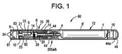
図1は、例示的な実施形態に従う不燃性喫煙装置60を示す。不燃性喫煙装置60は、交換可能なカートリッジ(または第一のセクション)70と、再利用可能な取り付け具(または第二のセクション)72を備え、これは、接続部205a/b(例えば、205aは、カートリッジ70上の雄ねじ接続部であり、205bは、再利用可能な取り付け具72上の雌ねじ接続部である)において、または、滑り嵌め、戻り止め、クランプ、または留め金のうちの少なくとも一つなどの他の便利品によって互いに結合される。第一のセクション70は、長軸方向に延在する外側管6(またはハウジング)と、外側管またはハウジング6の中に同軸に位置付けられる内側管62と、を含む。内側管62は、外側空気通路(またはチャネル)9を画定する。たばこ要素23は、外側空気通路9内にあり、かつヒーター14の下流にある。たばこ要素23は、多孔性アルミニウム管内にあってもよく、または多孔性形態に処理され、もしくは形成されてもよい。 FIG. 1 shows a
「たばこ要素」という用語は、例えば、たばこ葉、たばこプラグ、再構成たばこ、圧縮たばこロッドの形状または粉末を含むいくつかのたばこ植物材料を意味しうる。 The term "tobacco element" can mean any number of tobacco plant materials including, for example, tobacco leaves, tobacco plugs, reconstituted tobacco, compressed tobacco rod forms or powders.
たばこ要素23はまた、たばこシート、再構成たばこ葉または葉巻たばこラッパーなどのたばこで巻き付けられてもよい。 The
第二のセクション72も長軸方向に延在する外側管6’(またはハウジング)を含んでもよい。代替的な実施形態では、外側管6および6’を第一のセクション70と第二のセクション72との両方の単一のチューブハウジングとすることができ、また不燃性喫煙装置60全体を使い捨てとすることができる。 The
不燃性喫煙装置60はまた、内側管62と上流シール15とによって部分的に画定される中央空気通路20を含むことができる。さらに、不燃性喫煙装置60は、プレベイパー製剤供給貯蔵部22を含む。プレベイパー製剤供給貯蔵部22は、プレベイパー製剤材料および随意にその中にプレベイパー製剤材料を保存するように動作可能なプレベイパー製剤貯蔵媒体21を含む。 The
実施形態では、プレベイパー製剤供給貯蔵部22は、外側管6と内側管62との間の外側環状部内に収容される。環状部は、プレベイパー製剤材料のプレベイパー製剤供給貯蔵部22からの漏れを防ぐために、シール15によって上流端部において、およびプレベイパー製剤ガスケット10によって下流端部においてシールされる。 In an embodiment, pre-vapor
実施形態では、ヒーター14はまた、シール15によって画定される中央空気通路20の一部分の下流に、かつこれと離間した関係で、内側管62内に収容される。ヒーター14は、ワイヤコイル、平面体、セラミック体、単線、抵抗線のカゴ、またはその他の好適な形態でありうる。 In embodiments, the
芯28は、芯28がプレベイパー製剤材料をヒーター14と近接する関係で配置されるように、プレベイパー製剤供給貯蔵部22内のプレベイパー製剤材料と連通し、かつヒーター14と連通する。芯28は、繊維質かつ可撓性の材料で構築されてもよい。芯28は、プレベイパー製剤を引き出す能力を有する少なくとも一つのフィラメントを含んでもよい。例えば、芯28は、ガラス(またはセラミック)フィラメントを含みうるフィラメントの束を含んでもよい。別の実施形態では、束は、ガラスフィラメントの曲がりくねりの群(例えば、こうした曲がりくねりのうちの三つ)を備え、この配置はすべて、フィラメント間のすきま空間を介して毛細管作用によってプレベイパー製剤を引き出す能力を有する。
第二のセクション72内の電源1は、ヒーター14の両端に電圧をかけるために、ヒーター14へと動作可能に接続されうる(以下で説明されるように)。不燃性喫煙装置60は、中央空気通路20、内側管62の他の部分、またはその両方へと空気を送達するように動作可能である少なくとも一つの空気吸込み口44も含む。 A
図1~図2Bに示すように、不燃性喫煙装置60は、少なくとも二つの軸から離れた分岐出口24を有する口側の端部インサート8をさらに含む。口側の端部インサート8は、内側管62の内部およびガスケット10を通して延在する中央通路63を介して中央空気通路20と流体連通する。 As shown in FIGS. 1-2B, the
さらに、ヒーター14は長軸方向を横断する方向に延在し、プレベイパー製剤材料を気化して発生したベイパーを形成するのに十分な温度へとプレベイパー製剤材料を加熱する。他の実施形態において、ヒーター14は、長軸方向になどの別の様式に配置されうる。 Additionally, the
発生したベイパーはその後、陰圧を口側の端部インサート8に加えると、たばこ要素23内に流れる。ヒーター14は、ヒーター14が陰圧の印加の間にたばこ要素23を加熱するように、たばこ要素23から設定された距離にあってもよく、またはたばこ要素23に接触していてもよい。例えば、ヒーター14は、たばこ要素23から10ミリメートル未満に置かれてもよい。ヒーター14は、口側の端部インサート8において50℃の温度を生成するように配置されてもよい。さらに、ヒーター14は、たばこ要素23を50℃~200℃の温度に加熱し、プレベイパー製剤を400℃に加熱しうる。 The generated vapor then flows into the
ヒーター14は、たばこ要素23を温めるがたばこを燃焼しない。したがって、たばこ要素23の加温は不燃性と言及されうる。セクション70は、たばこ要素23およびヒーター14を含むので、セクション70は、不燃性喫煙要素と言及されうる。 The
図1を参照すると、芯28、プレベイパー製剤供給貯蔵部22、および口側の端部インサート8は、カートリッジ70内に収容され、また電源1は第二のセクション72内に収容される。一実施形態では、第一のセクション(カートリッジ)70は使い捨てであり、また第二のセクション(取り付け具)72は再使用可能である。上記で説明されたように、ねじ接続部205によって第一のセクション70と第二のセクション72とを取り付けることができ、これによってプレベイパー製剤供給貯蔵部22を使い尽くした時に下流のセクション70を交換することができる。分離した第一のセクション70と第二のセクション72とを有することは、数多くの利点を提供する。第一に、第一のセクション70が少なくとも一つのヒーター14、プレベイパー製剤供給貯蔵部22、および芯28を収容する場合、第一のセクション70が交換される時に、プレベイパー製剤と接触している可能性がある要素はすべて廃棄される。したがって、異なる口側の端部インサート8(例えば、異なるプレベイパー製剤材料を使用する場合)の間の二次汚染は起こらない。また、第一のセクション70が好適な間隔で交換される場合にも、ヒーターがプレベイパー製剤によって詰まるようになる可能性が低くなる。随意に、第一のセクション70および第二のセクション72は、係合された時に一緒に係止されるように配置される。 Referring to FIG. 1 ,
実施形態において、少なくとも一つの空気吸込み口44は、一つまた二つの空気吸込み口44、44’を含む。あるいは、三つ、四つ、五つ、またはそれ以上の空気吸込み口があってもよい。二つ以上の空気吸込み口44、44’がある場合、空気吸込み口44、44’は不燃性喫煙装置60に沿って異なる場所に位置する。例えば、図1に示すように、センサー16が陰圧の印加を感知するとヒーター14へ電力を供給するように、空気吸込み口44aを不燃性喫煙装置60の上流端部にセンサー16と隣接して位置付けることができる。空気吸込み口44aは、口側の端部インサートでの引き込みがセンサー16を有効にするように、口側の端部インサート8と通じるべきである。空気吸込み口44aからの空気はその後、電源1に沿って流れ、またシール15内の中央空気通路20、内側管62のその他の部分、または外側管6のうちの少なくとも一つへと流れることができる。少なくとも一つの追加的な空気吸込み口44、44’は、シール15に隣接し、かつその上流に、または任意の他の所望の場所に位置することができる。空気吸込み口44、44’のサイズおよび数を変化させることは、不燃性喫煙装置60の引き出し抵抗を確立することも助けることができる。 In embodiments, the at least one
一実施形態では、ヒーター14は芯28と連通し、またプレベイパー製剤材料を気化して発生したベイパーを形成するために十分な温度まで芯28の中に収容されたプレベイパー製剤材料を加熱するように配置される。 In one embodiment, the
ヒーター14は、芯28を囲むワイヤコイルであってもよい。好適な電気抵抗性材料の例としては、チタン、ジルコニウム、タンタル、および白金族由来の金属が挙げられる。適切な合金の実施例としては、ステンレス鋼、ニッケル含有、コバルト含有、クロミウム含有、アルミニウム含有、チタン含有、ジルコニウム含有、ハフニウム含有、ニオビウム含有、モリブデン含有、タンタル含有、タングステン含有、スズ含有、ガリウム含有、マンガン含有、および鉄含有合金、ならびにニッケル系、鉄系、コバルト系、およびステンレス鋼系の超合金が挙げられる。例えば、ヒーターは、ニッケルアルミナイド、表面上にアルミナの層をもつ材料、鉄アルミナイドおよび他の複合材料で形成されてもよく、電気抵抗性の材料は、必要とされるエネルギー伝達の動態学および外部の物理化学的性質に応じて、随意に断熱材料に埋め込み、封入、または断熱材料で被覆されてもよく、もしくはその逆であってもよい。一実施形態では、ヒーター14は、ステンレス鋼、銅、銅合金、ニッケル-クロム合金、超合金、およびこれらの組み合わせから成る群から選択される少なくとも一つの材料を含む。一実施形態では、ヒーター14は、ニッケル-クロム合金または鉄-クロム合金で形成される。一実施形態では、ヒーター14は、その外側表面上に電気的抵抗性層を有するセラミックヒーターであることができる。
別の実施形態において、ヒーター14は、一般に権利付与されたU.S.Pat.No.5,595,706 to Sikka et al.filed Dec.29,1994に記載されるような鉄アルミナイド(例えば、FeAlまたはFe.sub.3Al)またはニッケルアルミナイド(例えば、Ni.sub.3Al)で構成されてもよい。鉄アルミナイドの使用は特に、それらが高い比抵抗を示すという点で有利である。FeAlは、約180マイクロオームの比抵抗を示し、一方で、ステンレス鋼は、約50~91マイクロオームを示す。比抵抗が高いほど、電源(電池)1から引き出される、またはこれに負荷をかける電流が低くなる。 In another embodiment, the
一実施形態では、ヒーター14は、少なくとも部分的に芯28を囲むワイヤコイルを含む。その実施形態では、ワイヤーは、金属ワイヤーである。ヒーターコイルは、芯28の長さに沿って部分的に延在してもよい。ヒーターコイルは、芯28の周囲に全体的または部分的に延在しうる。別の実施形態では、ヒーターコイルは芯28と接触していない。 In one embodiment,
ヒーター14は、芯28の中のプレベイパー製剤を熱伝導によって加熱する。あるいは、ヒーター14からの熱は、熱伝導要素によってプレベイパー製剤へと伝導されてもよく、またはヒーター14は、使用中に不燃性喫煙装置60を通して引き込まれ、流入する周囲空気へと熱を伝達してもよく、その結果プレベイパー製剤を対流によって加熱する。
一実施形態では、芯は、セラミック材料またはセラミック繊維を含む。上述のように、芯28は、少なくとも部分的にヒーター14によって囲まれている。さらに、実施形態では、芯28の端部部分29、31がプレベイパー製剤供給貯蔵部22と接触するように、芯28は内側管62にある向かい合った開口部を通って延在する。 In one embodiment, the core comprises ceramic material or ceramic fibers. As noted above,
この芯28は、複数のフィラメントまたは一束のフィラメントを含みうる。一実施形態では、フィラメントは、不燃性喫煙装置60の長軸方向に対して横断方向に概して整列されてもよいが、例示的な実施形態はこの方向に限定されない。一実施形態では、芯28の構造は、ヒーター14に対するフィラメント間のすきま空間を介して毛細管作用によってプレベイパー製剤を引き出す能力を有するセラミックフィラメントを形成する。芯28は、略十字型、クローバー型、Y字型、または他の好適な形状の断面を有するフィラメントを含むことができる。 The core 28 may include multiple filaments or a bundle of filaments. In one embodiment, the filaments may be generally aligned transversely to the longitudinal direction of
芯28は、適切な任意の材料または材料の組み合わせを含む。適切な材料の例には、ガラスフィラメントおよびセラミックまたはグラファイトをベースにした材料がある。さらに、芯28は密度、粘性、表面張力および蒸気圧といった異なる物理特性を有するプレベイパー製剤に適応するように、適切な任意の毛細管を有する場合がある。プレベイパー製剤の特性と組み合わされた芯28の毛細管特性は、ヒーター14の過熱を避けるためにヒーター14の区域で芯28が常に湿潤状態になることを確実にする。
芯を使用する代わりに、ヒーター14は、十分な毛細管の多孔性材料であることができ、それは、迅速に熱を生成することができる高い電気抵抗を有する材料で形成された抵抗ヒーターと一体となる。 Instead of using a wick, the
その他の例示的な実施形態では、ヒーター14は、一緒に半円形に曲げられて組み合わされた二つの片を有するシート金属で作られうる。その他の例示的な実施形態では、ヒーター14は、芯28の内部に置かれる蛇行状ヒーター、メッシュヒーター、平板状ヒーター、NotchCoil(商標)を有するWismec Theoremヒーター、らせん状ヒーター、セラミック加熱フィルム、渦巻状ヒーター、またはプラチナヒーターのうちの少なくとも一つであってもよい。 In other exemplary embodiments, the
一実施形態では、芯28およびプレベイパー製剤供給貯蔵部22のプレベイパー製剤貯蔵媒体21は、アルミナセラミックで構築される。別の実施形態では、芯28はガラス繊維を含み、プレベイパー製剤貯蔵媒体21はセルロース系材料またはポリエチレンテレフタラートを含む。 In one embodiment, the
実施形態では、電源1は、不燃性喫煙装置60内で陽極が陰極の下流となるように配置された電池を含んでもよい。陽極コネクター4は電池の下流端部に接続する。ヒーター14は、二本の間隙を介した導線によって電池へと接続される。 In embodiments, the
ヒーター14および導線の巻かれていない端部部分27と端部部分27’(図4参照)との間の接続は導電性が高くかつ温度耐性がある一方で、ヒーター14は、接触によってではなく主にヒーター14に沿って発熱を生じるように抵抗が大きい。 While the connection between the
電池は、リチウム-イオン電池、またはその変形のうちの一つ(例えば、リチウム-イオンポリマー電池)であってもよい。あるいは、バッテリーは、ニッケル水素電池、ニッケルカドミウム電池、リチウムマンガン電池、リチウムコバルト電池、または燃料電池であってもよい。この場合、不燃性喫煙装置60は、電源のエネルギーが消耗するまで利用可能である。あるいは、電源1は充電式であってもよく、また電池を外部充電装置によって充電できるようにする回路を含んでもよい。この場合、充電する時、回路は所望の(あるいは、所定の)数の陰圧の適用に対する電力を提供し、その後は回路を外部充電装置へと再接続する必要がある。 The battery may be a lithium-ion battery, or one of its variations (eg, a lithium-ion polymer battery). Alternatively, the battery may be a nickel metal hydride battery, a nickel cadmium battery, a lithium manganese battery, a lithium cobalt battery, or a fuel cell. In this case, the
不燃性喫煙装置60は、センサー16を含む制御回路も含む。センサー16は、空気圧力の降下を感知し、電源1からヒーター14への電圧の印加を開始するように動作可能である。制御回路はまた、ヒーター14が作動している時に点灯するよう動作可能なヒーター作動灯48を含むことができる。一実施形態では、ヒーター作動灯48は、ヒーター作動灯(例えば、発光ダイオード(LED))48を含み、また陰圧が印加されている間にヒーター作動灯48が石炭燃焼中のように見えるように、不燃性喫煙装置60の上流端部にある。さらに、ヒーター作動灯48は、成人たばこ消費者から見えるように配置することができる。加えて、ヒーター作動灯48は、eベイピングシステムの診断に利用することができる。該灯48はまた、プライバシーのために、成人たばこ消費者が該灯48を有効化する、無効化する、または有効化および無効化を行うことができるように構成することができるため、該灯48は、所望であれば、ベイピング中でも有効化しないものとなる。
少なくとも一つの空気吸込み口44aは、センサー16が、陰圧を示す気流を感知し、電源1およびヒーター14が作動していることを示すためのヒーター作動灯48を起動させるようにセンサー16に隣接して位置する。 At least one
制御回路は、センサー16に組み込まれ、センサー16に応答して電力をヒーター14へと、例えば最大の時間リミッター付きで供給する。 A control circuit is incorporated in the
あるいは、制御回路は、陰圧の印加のために手動で動作可能なスイッチを含んでもよい。ヒーター14への電流供給の時間は、気化されるプレベイパー製剤の所望の量に応じて予め設定されてもよい。この目的のために、制御回路はプログラマブルであってもよい。あるいは、回路は、センサー16が圧力降下を検出する限り、電力をヒーターへと供給してもよい。 Alternatively, the control circuit may include a manually operable switch for application of the negative pressure. The duration of the current supply to
作動された時、ヒーター14は、ヒーターによって囲まれた芯28の一部分を約10秒間未満、より好ましくは約7秒間未満、加熱する。したがって、電力サイクルは、約2秒間~約10秒間(例えば、約3秒間~約9秒間、約4秒間~約8秒間、または約5秒間~約7秒間)の時間の範囲とすることができる。 When activated,
実施形態では、プレベイパー製剤供給貯蔵部22は、プレベイパー製剤材料を含むプレベイパー製剤貯蔵媒体21を含む。図1では、プレベイパー製剤供給貯蔵部22は、内側管62と外側管6との間、かつストッパー10とシール15との間の外側環状部内に収容される。したがって、プレベイパー製剤供給貯蔵部22は、中央空気通路20を少なくとも部分的に囲み、またヒーター14および芯28はプレベイパー製剤供給貯蔵部22の部分の間に延在する。 In embodiments, the pre-vapor
プレベイパー製剤貯蔵媒体21は、綿、ポリエチレン、ポリエステル、レーヨン、およびこれらの組み合わせの少なくとも一つを含む繊維質材料であってもよい。繊維は、約6ミクロン~約15ミクロン(例えば、約8ミクロン~約12ミクロン、または約9ミクロン~約11ミクロン)のサイズの範囲である直径を有してもよい。プレベイパー製剤貯蔵媒体21は、焼結材料、多孔性材料、または発泡性材料であってもよい。また、繊維は無関係にサイズ設定されてもよく、またY字形状、十字形状、クローバー形状、または任意の他の好適な形状の断面を有することができる。 Pre-vapor
別の例示的な実施形態では、プレベイパー製剤貯蔵媒体21は、たばこフィルターまたはたばこスラリーであってもよい。 In another exemplary embodiment, the pre-vapor
また、プレベイパー製剤材料は、不燃性喫煙装置60で使用するために好適な沸点を有する。沸点が高すぎる場合、ヒーター14は芯28内のプレベイパー製剤を気化することができない場合がある。しかし、沸点が低すぎる場合、ヒーター14が作動されていない間に、プレベイパー製剤の気化が起こる場合がある。 Also, the pre-vapor formulation material has a suitable boiling point for use in
プレベイパー製剤は、発生したベイパーに変換されうる材料または材料の組み合わせである。 例えば、プレベイパー製剤は、水、ビーズ、溶媒、活性成分、エタノール、植物抽出物、天然または人工の香料、グリセリンおよびプロピレングリコールなどのベイパー形成体、ならびにそれらの組み合わせを含むがこれに限定されない、液体、固体またはゲル製剤のうちの少なくとも一つであってもよい。 A pre-vapor formulation is an ingredient or combination of ingredients that can be converted into a generated vapor. For example, pre-vapor formulations include, but are not limited to, water, beads, solvents, active ingredients, ethanol, botanical extracts, natural or artificial flavors, vapor formers such as glycerin and propylene glycol, and combinations thereof. , solid or gel formulations.
プレベイパー製剤は、加熱に伴い放出される揮発性たばこ風味化合物を含むたばこ要素を含んでもよい。たばこ要素がプレベイパー製剤内にある時、たばこ要素の物理的整合性は保持される。例えば、たばこ要素は、プレベイパー製剤中の2~30重量パーセントであってもよい。 A pre-vapor formulation may comprise a tobacco element containing volatile tobacco flavor compounds that are released upon heating. The physical integrity of the tobacco elements is retained when the tobacco elements are within the pre-vapor formulation. For example, the tobacco component may be 2-30 weight percent in the pre-vapor formulation.
例えば、たばこ要素は、シートまたは断片の形態であり、プレベイパー製剤がプレベイパー製剤貯蔵媒体21に加えられた後に加えられうる。 For example, the tobacco element may be in sheet or piece form and added after the pre-vapor formulation is added to the pre-vapor
組み立てられた構成における不燃性喫煙装置60による動作時、陰圧は、口側の端部インサート8に印加されうる。この陰圧は、不燃性喫煙装置60内で内部圧力降下を引き起こすことができ、それは、空気吸込み口44/44’を経由して、入口気流が装置60に入るようにしうる。内部圧力降下はまた、空気が空気吸込み口44aを通って(セクション72を通じて延びる気流経路を介して)引き込まれるのにつれて、セクション72内の内部圧力降下を引き起こしうる。セクション72内に形成される内部圧力降下は、センサー16によって感知されうる。センサー16は次に、電源1を含む電気回路を遮断するように動作しうる。次に、導線は、ヒーター14を活性化するために、電流をヒーター14に運ぶ。活性化されたヒーター14は次に、芯28を介してヒーター14の方に引き込まれたプレベイパー製剤材料を加熱し、気化させる。 During operation with the
プレベイパー製剤材料は、芯28における毛細管作用によって、プレベイパー製剤供給貯蔵部22およびプレベイパー製剤貯蔵媒体21のうちの少なくとも一つからヒーター14の近傍に移動される。一実施形態では、図3に示すように、芯28は、第一の端部部分29と、第二の反対側の端部部分31と、を有する。第一の端部部分29および第二の端部部分31は、その中に収容されたプレベイパー製剤材料と接触するためにプレベイパー製剤貯蔵媒体21の向かい合う側面の中へと延在する。ヒーター14が作動される時に、芯28のその中央部分の中のプレベイパー製剤がヒーター14によって気化され、プレベイパー製剤材料を気化させて、発生したベイパーを形成するように、ヒーター14は芯28の中央部分を少なくとも部分的に囲む。陰圧が印加されることによって、発生したベイパーは、ヒーター14から、(香味付きのベイパーを生成するために)たばこ要素23を通って、さらに口側の端部インサート8の外へと流れる。 Pre-vapor formulation material is moved from at least one of pre-vapor
発生したベイパーは、たばこ要素をフローストリーム内へ溶出させうる。いくつかの熱的反応がまた、発生したベイパーとたばこ要素との間に存在しうる。 The generated vapor can leach tobacco elements into the flowstream. Some thermal reaction may also exist between the generated vapor and the tobacco element.
実施形態の一つの利点は、プレベイパー製剤供給貯蔵部22内のプレベイパー製剤材料が酸素から保護され(酸素は概して、芯を介してプレベイパー製剤貯蔵部分に入ることができないので)、その結果、プレベイパー製剤材料の劣化のリスクが著しく減少することである。さらに、外側管6が透明でないいくつかの実施形態では、プレベイパー製剤供給貯蔵部22が光から保護され、その結果、プレベイパー製剤材料の劣化のリスクが著しく減少する。従って、高いレベルの貯蔵寿命および清浄度を維持することができる。 One advantage of the embodiment is that the pre-vapor formulation material within the pre-vapor
図2Aおよび図2Bに示すように、口側の端部インサート8は少なくとも二つ(例えば、三つ、四つ、または五つ以上)の分岐する出口24を含む。口側の端部インサート8の出口24は、軸から離れた通路80の端部に位置し、また不燃性喫煙装置60の長軸方向に対して外向きの角度(すなわち、放散する角度)を有する。本明細書で使用される場合、「軸から離れた」という用語は不燃性喫煙装置60の長軸方向に対してある角度を有することを意味する。また、口側の端部インサート(または流れガイド)8は、使用時に、香味付きのベイパーを実質的に均一に分配するように、口側の端部インサート8の周りに均一に分布した出口を含んでもよい。したがって、ベイパーを単一の場所へと向かわせる軸上の単一のオリフィスのみを有するeベイピング装置と比較して、香味付きのベイパーは様々な方向に移動する。 As shown in FIGS. 2A and 2B, the
加えて、出口24および軸から離れた通路80は、口側の端部インサートにおける内部表面81および軸から離れた通路の内部表面のうちの少なくとも一つにおけるベイパー衝撃へと持ち込まれる気化されていないプレベイパー製剤の液滴が除去または分解されるように配置される。実施形態では、口側の端部インサートの出口は軸から離れた通路の端部に位置し、かつ使用時に香味付きのベイパーをより完全に分配し、液滴を除去するように、外側管6の中心軸に対して5~60度の角度を有してもよい。 In addition, the
各々の出口は、約0.015インチ~約0.090インチ(例えば、約0.020インチ~約0.040インチ、または約0.028インチ~約0.038インチ)の直径を有することが好ましい。所望する場合は、不燃性喫煙装置60の引き出し抵抗(RTD)を調節するために、出口の数とともに、出口24および軸から離れた通路80のサイズを選択することができる。 Each outlet can have a diameter of about 0.015 inch to about 0.090 inch (eg, about 0.020 inch to about 0.040 inch, or about 0.028 inch to about 0.038 inch). preferable. If desired, the number of outlets as well as the size of the
図1に示すように、口側の端部インサート8の内部表面81は、略ドーム型表面を含むことができる。あるいは、図2Bに示すように、口側の端部インサート8の内部表面81’は、略平面状の端部表面を有する円筒状または円錐台状であることができる。内部表面は、その表面にわたって実質的に均一であり、または口側の端部インサート8の長軸方向軸を中心として対称である。しかし、他の実施形態では、内部表面は不規則な形状であることができ、他の形状を有することができ、またはその両方であることができる。 As shown in FIG. 1, the
口側の端部インサート8は、セクション70の外側管6の中に一体的に取り付けられてもよい。さらに、口側の端部インサート8は、低密度ポリエチレン、高密度ポリエチレン、ポリプロピレン、ポリ塩化ビニル、ポリエーテルエーテルケトン(PEEK)、およびこれらの組み合わせから成る群から選択されるポリマーで形成されてもよい。所望する場合、口側の端部インサート8は着色されてもよい。
実施形態では、不燃性喫煙装置60はまた、気流ダイバータまたは気流ダイバータ手段の種々の実施形態を含む。気流ダイバータは、引き込まれた空気がヒーターを冷却する傾向を弱めるようにヒーターにおけるまたはそのおおよそ周りの気流を管理するように動作可能であり、そうしないとベイパー放出の低下をもたらす可能性がある。 In embodiments, the
一実施形態では、図3および図4に示すように、不燃性喫煙装置60は、シール15内の中央空気通路20の下流端部82において不浸透性プラグ30を含む気流ダイバータを含むことができる。中央空気通路20は、シール15および内側管62内で軸方向に延在する中央通路である。シール15は、外側管6と内側管62との間の環状部の上流端部をシールする。気流ダイバータは、中央空気通路20からの空気を内側管62に向かって外向きに、およびシール15の下流端部部分の外側周辺と内側管62の内壁との間に画定される外側空気通路9の中へと方向付けるための少なくとも一つの半径方向空気チャネル32を含んでもよい。 In one embodiment, as shown in FIGS. 3 and 4, the
中央空気通路20の穴の直径は、少なくとも一つの半径方向空気チャネル32の直径と実質的に同一である。さらに、中央空気通路20の穴および少なくとも一つの半径方向空気チャネル32の直径は、約1.5ミリメートル~約3.5ミリメートル(例えば、約2.0ミリメートル~約3.0mm)の範囲であってもよい。随意に、不燃性喫煙装置60の引き出し抵抗を制御するために、中央空気通路20の穴および少なくとも一つの半径方向空気チャネル32の直径を調節することができる。使用時に、気流のより小さい部分がヒーター14の中央部分に方向付けられるように、空気は中央空気通路20の穴の中へ、少なくとも一つの半径方向空気チャネル32を通して、そして外側空気通路9の中へと流れ、これにより加熱サイクルの間ヒーター14上の気流の前述の冷却効果を減少または最小化する。したがって、入ってくる空気は、ヒーター14の中央から遠ざかるように方向付けられ、またヒーターを通過する空気速度は、空気がヒーター14の中央部分に真っ直ぐ沿って方向付けられたシール15の中央開口部を通って流れる時と比較して減少する。 The bore diameter of the
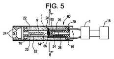
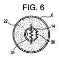
別の実施形態では、図5および図6に示すように、気流ダイバータは、シール15の下流端部およびヒーター14との間に位置付けられたディスク34の形状であることができる。ディスク34は、外側管状壁90の下流端部における横軸方向の壁内に少なくとも一つの開口部36を含む。少なくとも一つの開口部36は、入ってくる空気が管62の内側壁の方へ外側に方向付けられるように軸から離れていてもよい。陰圧の印加の間、ディスク34は、成人たばこ消費者による強くまたは長い吸い込みの結果として気流の傾向に反作用してヒーターを冷却するように、ヒーター14の中央部分から離れて気流を分岐させるように動作可能である。したがって、ヒーター14は、陰圧の印加の間に生成されたベイパー量における液滴を減少し、または防ぐように、加熱サイクルの間の冷却を実質的に減少し、または防ぐ。 In another embodiment, the airflow diverter can be in the form of a
さらに別の実施形態では、図7に示すように、気流ダイバータは、短い中央空気通路20の下流端部82から延在する円錐台状のセクション40を含む。他の実施形態と比較して中央空気通路20を短くすることによって、ヒーター14は、中央空気通路20から遠く離れて位置付けられ、それはヒーター14と接触する前に気流の速度を落とすことを許容し、気流の傾向を少なくしてヒーター14を冷却する。あるいは、ヒーター14は、口側の端部インサート8の近くに、かつ中央空気通路20から遠く離れて移動し、十分な時間、十分な空間、または十分な時間かつ空間において気流が速度を落とすことを許容し、同様の冷却減少効果を達成することができる。 In yet another embodiment, the airflow diverter includes a frusto-
円錐台状のセクション40の付加により、気流の速度を落とすことができるより大きな直径のサイズの穴が提供され、その結果、ヒーター14におけるまたはヒーター14の周りでの気流速度が、陰圧サイクルの間のヒーター14上の空気の冷却効果を弱めるように減少する。円錐台状のセクション40の大きい方(出口)の端部の直径は、約2.0ミリメートル~約4.0ミリメートルの範囲であり、好ましくは約2.5ミリメートル~約3.5ミリメートルの範囲である。 The addition of the frusto-
中央空気通路20の穴の直径および円錐台状のセクション40の小さい端部、大きい端部、または小さいおよび大きい端部の直径は、不燃性喫煙装置60の引き出し抵抗を制御するように調節されうる。 The diameter of the hole in the
種々の実施形態の気流ダイバータは、気流速度(気流の速度、気流の方向、またはその速度および方向)を制御することによって気流の向きを変える。例えば、気流ダイバータは、特定の方向に気流を向けること、気流の速度を制御すること、またはその両方を行うことができる。気流の速度は、気流経路の断面積を変えることによって制御されてもよい。収縮したセクションを通る気流は、速度を増大する一方で、幅の広いセクションを通る気流は、速度を減少する。 The airflow diverter of various embodiments redirects the airflow by controlling the airflow velocity (the speed of the airflow, the direction of the airflow, or its speed and direction). For example, an airflow diverter can direct the airflow in a particular direction, control the speed of the airflow, or both. Airflow velocity may be controlled by varying the cross-sectional area of the airflow path. Airflow through a constricted section increases velocity, while airflow through a wider section decreases velocity.
外側管6、内側管62、またはその両方は、任意の適切な材料または材料の組み合わせで形成されうる。適切な材料の例としては、金属、合金、プラスチック、もしくはそれらの材料のうちの一つ以上を含有する複合材料、または、例えば、ポリプロピレン、ポリエーテルエーテルケトン(PEEK)、セラミック、およびポリエチレンなど、食品または医薬品の用途に適切な熱可塑性樹脂が挙げられる。一実施形態では、材料は軽量であり、脆くない。
図8に示すように、不燃性喫煙装置60はまた、不燃性喫煙装置60の第一のセクション70に隣接した外側管6の周りで取り外し可能に、回転可能に、または取り外し可能に、かつ回転可能に位置付けられるスリーブ組立品87を含むことができる。さらに、スリーブ組立品87は、成人たばこ消費者に送達する前に発生したベイパーの温度を維持するように第一のセクション70の少なくとも一部分を断熱する。実施形態では、スリーブ組立品87は、不燃性喫煙装置60の周りで回転可能であり、溝穴88が第一のセクション70において空気吸込み口44と並び、陰圧が不燃性喫煙装置60に印加された時に空気が不燃性喫煙装置60内へ通ることを許容するように、スリーブ組立品の周りに横軸方向に間隔をおいて配置される溝穴88を含む。ベイピングの前またはベイピングの間、成人たばこ消費者は、空気吸込み口44がスリーブ組立品87によって少なくとも部分的に塞がれるようにスリーブ組立品87を回転させることができ、それによって、不燃性喫煙装置60の引き出し抵抗、換気、またはその両方を調節する。 As shown in FIG. 8, the
スリーブ組立品87は、シリコーンまたは他の柔軟な材料で作られ、それは柔らかい口あたりを成人たばこ消費者に提供する。しかし、スリーブ組立品87は、一つ以上の部分で形成されてもよく、プラスチック、金属およびその組み合わせを含む様々な材料から形成されてもよい。実施形態では、スリーブ組立品87は、シリコーンで形成される単一の部分である。スリーブ組立品87は、他の不燃性喫煙装置とともに取り外されても、再利用されてもよく、または第一のセクション70とともに廃棄されてもよい。スリーブ組立品87は、任意の適切な色であってもよく、グラフィック、またはその他のしるし、またはその両方を含むことができる。
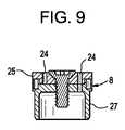
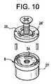
図9および図10に示すように、代替の実施形態では、不燃性喫煙装置は、動かない部分27および回転可能な部分25を有する口側の端部インサート8を含むことができる。出口24、24’は、動かない部分27および回転可能な部分25のそれぞれに位置する。出口24、24’のうち一つ以上は、示したように位置合わせされ、香味付きのベイパーが成人たばこ消費者の口に入ることを許容する。しかし、回転可能な部分25は、動かない部分27における出口24のうち一つ以上を少なくとも部分的に塞ぐように口側の端部インサート8内を回転することができる。したがって、出口の香味付きのベイパー量は、陰圧の各印加で変化されうる。出口24、24’は、出口24、24’が分岐するように口側の端部インサート8に形成されうる。 As shown in FIGS. 9 and 10, in an alternative embodiment, the non-combustible smoking device may include a
別の実施形態では、気流ダイバータは、ヒーター14に隣接するがすぐ上流にある追加的な第二の芯要素を含む。第二の芯要素は、ヒーター14の周りで気流の部分を分岐させる。 In another embodiment, the airflow diverter includes an additional second wick element adjacent to but immediately upstream of
図1、図3、図5、図7および図8は、外側空気通路内にたばこ要素を示すが、例示的な実施形態はそれに限定されない。 Although FIGS. 1, 3, 5, 7 and 8 show tobacco elements within the outer air passageway, exemplary embodiments are not so limited.
図11Aは、たばこ要素1150を含む不燃性喫煙装置1100の例示的な実施形態を示す。不燃性喫煙装置1100は、不燃性喫煙装置60と類似している。したがって、簡潔性のために異なる部分のみを説明する。 11A shows an exemplary embodiment of a
不燃性喫煙装置1100は、プレベイパー製剤供給貯蔵部22aを含む。プレベイパー製剤供給貯蔵部22aは、プレベイパー製剤供給貯蔵部22aが長軸方向において短いことを除いて、プレベイパー製剤供給貯蔵部22と同様である。 The
第一のセクション70aは、長軸方向に延在する外側管6(またはハウジング)と、外側管またはハウジング6の中に同軸に位置付けられる内側管62aと、を含む。内側管62aは、第一の外側空気通路9aを画定する。第一の外側空気通路9aは、第二の外側空気通路9bに通じている。 The
内側管62aの端部および口側の端部インサート8は、第二の外側空気通路9bを画定する。別の言い方をすると、外側管6は、第二の外側空気通路9bの緯度方向における直径を画定しうる。示すように、第二の外側空気通路9bの緯度方向における直径は、第一の外側空気通路9aの緯度方向における直径より大きい。 The end of the
たばこ要素1150は第二の外側空気通路9b内にある。たばこ要素1150は、例えば、口側の端部インサート8を取り外して、たばこ要素1150を第二の外側空気通路9b内に挿入することによって、第二の外側空気通路9b内に挿入されてもよい。 A
たばこ要素1150は、たばこストランド、巻かれたたばこ、またはフィルターを含むがそれらに限定されない、圧縮された形態のたばこを意味するたばこプラグであってもよい。たばこプラグは、例えば、天然のたばこ、再構成シートたばこ、またはアルミニウムで巻き付けられてもよい。ただ一つのたばこプラグが示されているが、複数のたばこプラグが使用されてもよいことは理解されるべきである。繊維状セグメント(例えば、酢酸セルロース、他の合成ファイバー、または天然ファイバー)が、複数のたばこプラグの間に配置されてもよい。
例えば、円筒形のハウジング1185はたばこを保持する。円筒形のハウジング1185は、例えば、アルミニウムで作られうる。円筒形のハウジング1185は、外側空気通路9bの直径に適合する外径を有する。ハウジング6の長軸方向軸に沿って、メッシュスクリーン1175および1180は、円筒形のハウジング1185の端部に適合し、円筒形のハウジング1185内でたばこを囲む。図11Aに示すように、メッシュスクリーン1175および1180は、空気が円筒形のハウジングの一方の端部からたばこを通って、口側の端部インサート8に最も近い円筒形のハウジング1185の端部の外へ通ることを可能にする開口部1182を含む。 For example,
たばこ要素1150は、ヒーター14によって生成される発生したベイパーがたばこを通り抜けることができるように配置される。例えば、たばこ要素1150は、口側の端部インサート8からの第一の距離およびプレベイパー製剤供給貯蔵部22からの第二の距離の間隔において配置されうる。第一の距離および第二の距離は、同一であってもよく、または異なっていてもよい。
陰圧が印加されることによって、発生したベイパーは、ヒーター14から、たばこ要素1150を通って、さらに口側の端部インサート8の外へと流れる。ヒーター14は、たばこ要素1150から設定された距離にあってもよく、またはたばこ要素1150と接触していてもよく、したがって、ヒーター14は、陰圧の印加の間、たばこをある温度(上記で説明されたような)に加熱する。実施例では、ヒーター14は、たばこ要素1150から1~5ミリメートルに置かれてもよい。 The applied negative pressure causes the generated vapor to flow from the
内側管62aは、口側の端部インサート8に対して長軸方向にヒーター14を通って延在するように示されているが、ヒーター14は、第二の外側空気通路9b内に延在するように配置されてもよいことが理解されるべきである。結果として、たばこ要素1150は、ヒーター14から間隔をおいて配置されてもよく、または図11Bに示すように、ヒーター14と接触していてもよい。図11Bでは、ヒーター14は、セクション70bの第二の外側空気通路9b内にある。したがって、プレベイパー製剤供給貯蔵部11a、ヒーター14、およびたばこ要素1150は、連続的に配置される。 Although the
ガスケット10が示されていないが、不燃性喫煙装置11は、ガスケット10を含んでもよい。 Non-combustible smoking device 11 may include
図12は、不燃性喫煙装置1200の例示的な実施形態を示す。図12は、たばこ要素1250を含む不燃性喫煙装置1200の例示的な実施形態を示す。不燃性喫煙装置1200は、セクション70cが口側の端部インサート8、たばこ要素23およびガスケット10を含まないことを除いて不燃性喫煙装置60と類似しており、不燃性喫煙装置1200はさらに、インサート1210を含む。したがって、簡潔性のために異なる部分のみを説明する。 FIG. 12 shows an exemplary embodiment of a
口側の端部インサート8およびガスケット10を取り除くことにより、不燃性喫煙装置1200は、たばこインサート1210を受けるように嵌合する受入れ区域1205を含む。受入れ区域1205は、外側管6およびプレベイパー製剤供給貯蔵部22の端部によって画定される。 By removing
たばこインサート1210は、紙巻たばこまたは葉巻たばこであってもよい。例えば、たばこインサートは、例えば、フィルター付きの紙巻たばこ、フィルターのない紙巻たばこ、シガリロ、フィルター付きの葉巻たばこフィルター、先端部がある葉巻たばこ、または先端部のない葉巻たばこもしくはシガリロであってもよい。しかしながら、例示的な実施形態は、それに限定されない。
たばこインサート1210は、着脱可能なインサートである。図12に示す実施例では、たばこインサート1210は、紙巻たばこまたは紙巻たばこの一部分であってもよい。たばこインサート1210は、フィルター1220およびたばこ要素1250を含む。たばこインサートが先端部のない葉巻たばこまたはシガリロである例示的な実施形態では、たばこインサートは、フィルターを含まない。
チッピングペーパー1255は、フィルター1220およびたばこ要素1250と部分的に重なりうる。チッピングペーパー1255は、外側管6に沿って延在するたばこインサート1210の表面区域を覆いうる。したがって、チッピングペーパー1255は、剛性をたばこインサート1210に提供し、受入れ区域1205への容易な挿入を可能にする。アルミ箔がまた、追加的なチッピングペーパーを用いて、または用いずに、たばこ要素1250を収容するために使用されてもよい。
ヒーター14の位置は、図12に示す位置に限定されない。例えば、ヒーター14は、ヒーター14がたばこ要素1250に近接する、たばこ要素1250と接触する、またはその両方であるように、外側空気通路9の端部に位置付けられてもよい。別の例示的な実施形態では、ヒーター14は、図11Bに示すものと同様に、外側空気通路9の外へ突出していてもよい。 The position of
ヒーター14は、たばこ要素1250から設定された距離にあってもよく、またはたばこ要素1250と接触していてもよく、したがって、ヒーター14は、陰圧の印加の間、たばこ要素1250をある温度(上記で説明されたような)に加熱する。 The
組み立てられた構成における不燃性喫煙装置1200による動作時、陰圧は、たばこインサート1210に印加されうる。陰圧は、不燃性喫煙装置1200内で内部圧力降下を引き起こすことができ、それは、空気吸込み口44/44’を経由して、入口気流が装置1200に入るようにしうる。内部圧力降下はまた、空気が空気吸込み口44aを通って(セクション72を通じて延びる気流経路を介して)引き込まれるのにつれて、セクション72内の内部圧力降下を引き起こしうる。セクション72内に形成される内部圧力降下は、センサー16によって感知されうる。センサー16は次に、電源1を含む電気回路を遮断するように動作しうる。次に、導線は、ヒーター14を活性化するために、電流をヒーター14に運ぶ。活性化されたヒーター14は次に、芯28を介してヒーター14の方に引き込まれたプレベイパー製剤の一部分を加熱し、気化させる。 A negative pressure may be applied to the
プレベイパー製剤材料は、芯28における毛細管作用によって、プレベイパー製剤供給貯蔵部22およびプレベイパー製剤貯蔵媒体21のうちの少なくとも一つからヒーター14の近傍に移動される。ヒーター14が作動される時に、芯28のその中央部分の中のプレベイパー製剤は、ヒーター14によって気化され、プレベイパー製剤材料を気化させて、発生したベイパーを形成する。陰圧が印加されることによって、発生したベイパーは、ヒーター14から、(たばこ風味ベイパーを形成するために)たばこ要素1250を通って、さらにフィルター1220の外へと流れる。 Pre-vapor formulation material is moved from at least one of pre-vapor
図12に示す実施例では、フィルター1220は、酢酸セルロース(CA)フィルターであってもよい。トリアセチンなどのCAフィルター要素は、発生したベイパーに溶出されうる。発生したベイパーにおける蒸気相ニコチンおよび他の揮発性要素は、たばこの存在によって減少されうる。 In the example shown in FIG. 12,
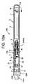
図13Aは、不燃性喫煙装置1300の例示的な実施形態を示す。 FIG. 13A shows an exemplary embodiment of a
不燃性喫煙装置1300は、セクション70dがたばこ要素23を含まないことを除いて不燃性喫煙装置60と類似しており、不燃性喫煙装置1300はさらに、着脱可能なマウスピース1310を含む。したがって、簡潔性のために異なる部分のみを説明する。
着脱可能なマウスピース1310は、たばこ要素1320を含む。たばこ要素1320は、プラグまたはバッグ内に収容され、マウスピース1310の内部に取り付けられうる。着脱可能なマウスピース1310は、外側管6の一部分にわたって適合し、着脱可能なマウスピースとセクション70dとの間にシールを形成する。着脱可能なマウスピース1310は、外側管6上に摺動する、または接続機構(例えば、雄/雌)を用いて外側管6に接続することによってシールを形成しうる。
組み立てられた構成における不燃性喫煙装置1300による動作時、陰圧は、着脱可能なマウスピース1310に印加されうる。陰圧が印加されることによって、発生したベイパーは、ヒーター14から、口側の端部インサート8を通って、たばこ要素1320内へ、さらに空気通路1330を通って着脱可能なマウスピース1310の外へと流れる。 Negative pressure may be applied to the
ヒーター14は、たばこ要素1320から設定された距離にあってもよく、またはたばこ要素1320と接触していてもよく、したがって、ヒーター14は、陰圧の印加の間、たばこ要素1320をある温度(上記で説明されたような)に加熱する。 The
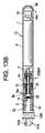
別の例示的な実施形態では、口側の端部インサート8およびガスケット10は、図13Bに示すように省かれてもよい。図13Bに示す実施形態では、管6aは図13Aの管6よりも短い。 In another exemplary embodiment, the
他の例示的な実施形態では、たばこ要素は、プレベイパー製剤供給貯蔵部内にあってもよく、プレベイパー製剤プレベイパー製剤貯蔵媒体として機能してもよく、またはその両方であってもよい。 In other exemplary embodiments, the tobacco component may be in the pre-vapor formulation supply reservoir, may function as a pre-vapor formulation pre-vapor formulation storage medium, or both.
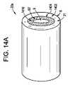
例えば、図14Aおよび図14Bは、プレベイパー製剤供給貯蔵部の例示的な実施形態を示す。プレベイパー製剤供給貯蔵部22aは、プレベイパー製剤供給貯蔵部22のように用いられうる。 For example, Figures 14A and 14B show an exemplary embodiment of a pre-vapor formulation supply reservoir. Pre-vapor
示されるように、プレベイパー製剤供給貯蔵部22aは、プレベイパー製剤1402、中間管1404、たばこ要素1410、および内側管62’を含む。内側管62’は、空気通路9を画定し、例えば、金属グリッド、スクリーンまたはメッシュを含みうる。 As shown, pre-vapor
別の例示的な実施形態では、内側管62’は、任意の適切な材料または材料の組み合わせで形成されうる内側管62であってもよい。適切な材料の例としては、金属、合金、プラスチック、もしくはそれらの材料のうちの一つ以上を含有する複合材料、または、例えば、ポリプロピレン、ポリエーテルエーテルケトン(PEEK)、セラミック、およびポリエチレンなど、食品または医薬品の用途に適切な熱可塑性樹脂が挙げられる。 In another exemplary embodiment, inner tube 62' may be
中間管1404はガラス繊維を含んでもよい。プレベイパー製剤1402は、中間管1404と外側管6との間にあり、またプレベイパー製剤貯蔵媒体21内にあってもよい。
たばこ要素1410は、内側管62’と中間管1404との間にある。たばこ要素1410は、例えば、たばこシート、断片、粉末、ビーズ、またはスポンジであってもよい。内側管62’は、熱伝達を助けるためにたばこ内に突出するエクステンダーを含んでもよい。
動作時、陰圧が不燃性喫煙装置に印加され、上記で説明されたように、それはヒーター14を起動しうる。ヒーターは、プレベイパー製剤1402を加熱して発生したベイパーを形成し、その発生したベイパーは、ヒーター14から、(たばこ風味ベイパーを形成するために)たばこ要素1410を通って、さらに空気通路9内へと流れる。 In operation, negative pressure is applied to the non-combustible smoking device, which may activate the
結果として、たばこ要素1410は、発生したベイパーによる熱、またヒーター14による熱に晒される。したがって、たばこアロマが発生したベイパーに与えられる。 As a result, the
例示的な実施形態では、不燃性喫煙装置内のある量のたばこ要素(例えば、フィルター)は、紙巻たばこの場合とおおよそ同様の数の陰圧の印加をもたらしうる。あるいは、ある量のたばこ要素は、決まった数の陰圧の印加をもたらしうる。 In an exemplary embodiment, a quantity of tobacco elements (eg, filters) within a non-combustible smoking device may result in approximately the same number of negative pressure applications as with cigarettes. Alternatively, a certain amount of tobacco element may result in a fixed number of negative pressure applications.
例示的な実施形態において、たばこ要素はニコチンを除去されていてもよい。 In exemplary embodiments, the tobacco component may be denicotine.
図1~図14Bで説明された例示的な実施形態は、二つ以上の位置におけるたばこ要素を利用するように組み合わされうる。例えば、第一のたばこ要素は、プレベイパー製剤供給貯蔵部内でプレベイパー製剤と組み合わせることができ、第二のたばこ要素は、通路9内にあってもよい。他の例示的な実施形態において、第一のたばこ要素は、プレベイパー製剤供給貯蔵部内でプレベイパー製剤と組み合わせることができ、第二のたばこ要素は、第二の外側空気通路9bにおけるたばこプラグであってもよい。別の例示的な実施形態において、第一のたばこ要素は、プレベイパー製剤供給貯蔵部内でプレベイパー製剤と組み合わせることができ、第二のたばこ要素は、インサートまたは着脱可能なマウスピース内にあってもよい。別の例示的な実施形態において、第一のたばこ要素は、通路9内にあることができ、第二のたばこ要素は、インサートまたは着脱可能なマウスピース内にあってもよい。 The exemplary embodiments described in FIGS. 1-14B can be combined to utilize tobacco elements in more than one position. For example, a first tobacco component may be combined with a pre-vapor formulation within a pre-vapor formulation supply reservoir and a second tobacco component may be within
例示的な実施形態は、プレベイパー製剤を加熱し、また熱をたばこ要素に提供しうるヒーターを有する不燃性喫煙装置を提供する。より詳細には、例示的な実施形態による不燃性喫煙装置は、発生したベイパーをたばこ要素に晒し、プレベイパー製剤をたばこ要素に晒し、またはその両方を行う。たばこ要素がプレベイパー製剤内にある時、たばこ要素の物理的整合性は保持される。 An exemplary embodiment provides a non-combustible smoking device having a heater that can heat the pre-vapor formulation and provide heat to the tobacco element. More specifically, non-combustible smoking devices according to exemplary embodiments expose generated vapor to tobacco elements, pre-vapor formulations to tobacco elements, or both. The physical integrity of the tobacco elements is retained when the tobacco elements are within the pre-vapor formulation.
他の例示的な実施形態では、不燃性喫煙装置は、発生したベイパーをたばこ要素に晒し、プレベイパー製剤をたばこ要素に晒し、またはその両方を行うポッド装置またはタンク装置であることができる。 In other exemplary embodiments, the non-combustible smoking device can be a pod or tank device that exposes generated vapor to tobacco elements, pre-vapor formulations to tobacco elements, or both.
単一のヒーターが図1~図14Bに関して説明されたが、例示的な実施形態は、複数のヒーター不燃性喫煙装置を含んでもよい。第一のヒーターは、プレベイパー製剤を気化させるためのヒーター14であってもよく、第二のヒーターは、たばこ要素を加熱するために使用されてもよい。第二のヒーターは、たばこ要素を貫通していてもよい。 Although a single heater has been described with respect to FIGS. 1-14B, exemplary embodiments may include multiple heater non-combustible smoking devices. A first heater may be the
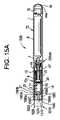
図15A~図15Cは、不燃性喫煙装置1500の例示的な実施形態を示す。図15Bは、不燃性喫煙装置1500の例示的な実施形態の半分解図を示す。図15Cは、ガスケット1560および気流要素1570の平面図を示す。 15A-15C illustrate an exemplary embodiment of a
図15Aは、たばこ要素1550を収容するたばこハウジング1540を含む不燃性喫煙装置1500の例示的な実施形態を示す。不燃性喫煙装置1500は、セクション70cが口側の端部インサート8およびたばこ要素23を含まないことを除いて不燃性喫煙装置60と類似しており、不燃性喫煙装置1500はさらに、インサート1510を含む。したがって、簡潔性のために異なる部分のみを説明する。 FIG. 15A shows an exemplary embodiment of a
不燃性喫煙装置1500は、インサート1510を受けるように嵌合する受入れ区域1505を含む。受入れ区域1505は、外側管6およびガスケット10によって画定される。
たばこインサート1510は、ガスケット1560および気流要素1570を含む紙巻たばこまたは葉巻たばこであってもよい。例えば、たばこインサート1510は、例えば、フィルター付きの紙巻たばこ、フィルターのない紙巻たばこ、シガリロ、フィルター付きの葉巻たばこフィルター、先端部がある葉巻たばこ、または先端部のない葉巻たばこ/シガリロであってもよい。しかしながら、例示的な実施形態は、それに限定されない。
たばこインサート1510は、着脱可能なインサートである。
たばこインサート1510は、フィルター1520、たばこハウジング1540、ガスケット1560、および気流要素1570を含む。ガスケット1560のみが図15Aに示される一方で、追加的なガスケットが存在してもよいことは理解されるべきである。例えば、長い気流要素のために、第二のガスケットが、管を安定させるためにたばこハウジング1540とフィルター1520との間に用いられてもよい。実施例では、たばこハウジング1540は、長軸方向における15~25ミリメートルの長さ、および8ミリメートルの幅を有しうる。
ガスケット1560は、ガスケット10とたばこ要素1550との間にある。ガスケット1560は、たばこ要素1550がチャネル9内に漏れることを防ぎ、気流要素1570を保持する。
ガスケット1560は、円柱状の受入れ部分1560aおよび穴1560bを含む。穴1560bは、チャネル9をたばこ要素1550に接続し、したがって、発生したベイパーがチャネル9からたばこ要素1550内に、ついで、フィルター1520内に流れることが可能となる。気流要素1570は、気流要素1570を円柱状の受入れ部分1560a内に挿入することによって、ガスケット1560に取り付けられる。気流要素1570および円柱状の受入れ部分1560aは、フェルールを用いて接続されてもよい。例えば、特定の識別を有するフェルールが、その特定の識別に対応する気流要素1570とともに用いられてもよい。フェルールは、その際、ガスケット1560内に組み込まれる。あるいは、気流要素1570は、受入れ部分1560aに接着される。
図15Cは、ガスケット1560および気流要素1570の構成をより詳細に示す。示されるように、受入れ部分1560aは、ガスケット1560のベース部1560cから突出する。ベース部1560cは円形状である。穴1560bは、受入れ部分1560aの長軸方向において、第一の露出表面から第二の露出表面へとベース部1560cを通じて延在する。 FIG. 15C shows the configuration of
図15Aに戻って参照すると、気流要素1570は、たばこハウジング1540を通じて装置1500の長軸方向に延在する。別の言い方をすると、気流要素1570は、チャネル9からフィルター1520への空気通路を提供する。気流要素1570は、PEEKおよびステンレス鋼のうちの少なくとも一つで作られる毛細管であってもよい。 Referring back to FIG. 15A,
気流要素1570は、たばこハウジング1540の第一の端部分からたばこハウジング1540の対向する第二の端部分まで長軸方向に延在する。気流要素1570は、貯蔵部に最も近いガスケット1560の一部分からフィルター1520へと延在する、円柱状の表面1572を含む。チャネル1574は、貯蔵部に最も近いガスケット1560の一部分からフィルター1520へと延在する気流要素1570の内径(ID)である、気流要素1570の内側表面領域により画定される。気流要素1570は、所望の量の発生したベイパー(例えば、20パーセント)がたばこ要素1550を通過することなく、ハウジング1540を通って流れることを可能にする。残りの量の発生したベイパー(例えば、80パーセント)は、たばこ要素1550を通り抜ける。気流要素1570は、たばこ要素1550に晒されない所望の量の発生したベイパーがたばこ要素1550と反応することを防ぐ。例示的な実施形態では、たばこ要素1550を通過することなく、ハウジング1540を通って流れる所望の量の発生したベイパーは、65パーセントである。
気流要素1570のサイズ(例えば、内部体積)は、チャネル1574を通って流れる所望の量の発生したベイパーに基づく。例示的な実施形態では、気流要素1570は、0.5ミリメートル~3ミリメートルの内径および0.5~1.5ミリメートルの外径を有する。その他の例示的な実施形態では、気流要素1570は、2ミリメートル~2.5ミリメートルの内径を有する。例示的な実施形態では、気流要素1570は、1.59ミリメートルの外径および1.02ミリメートルの内径を有する。気流要素1570は、15~25ミリメートルの長さであってもよいが、ハウジング6の長さに基づいて、長くてもまたは短くてもよい。気流要素1570は、一定の内径または変化する内径を有してもよい。 The size (eg, internal volume) of
図15Aに示す実施形態では、気流要素1570は、たばこ要素1550を二つの等しい半分部分1550aと1550bに区分する。しかし、気流要素1570は、発生したベイパーがたばこ要素1550を通過することなく、ハウジング1540を通って流れることを可能にする任意の位置に置かれてもよい。加えて、複数の気流要素が、たばこ要素1550に晒されない所望の量の発生したベイパーを生成するための一つのものの代わりに用いられてもよい。気流要素1570は、フィルター1520に向かって直線状、らせん状または曲線状であることができる。 In the embodiment shown in Figure 15A, the
凝縮を避けるために、気流要素1570は加熱されうる。加熱した時に、気流要素1570はまた、たばこ要素1550に熱を提供する。例えば、気流要素1570およびガスケット1560は、導電材料(例えば、ステンレス鋼)で作られうる。ガスケット1560は、ヒーター14に接続されて、気流要素1570に熱を伝導する。ガスケット1560は、ヒーター14からガスケット1560までハウジング6に沿ったワイヤーによって、ヒーター14に接続されてもよい。
チッピングペーパー1555は、フィルター1520およびたばこハウジング1540と部分的に重なりうる。チッピングペーパー1555は、外側管6に沿って延在するたばこインサート1510の表面区域を覆いうる。したがって、チッピングペーパー1555は、剛性をたばこインサート1510に提供し、受入れ区域1505への容易な挿入を可能にする。アルミ箔がまた、追加的なチッピングペーパーを用いて、または用いずに、たばこ要素1550を収容するために使用されてもよい。
ヒーター14の位置は、図15Aに示す位置に限定されない。例えば、ヒーター14は、ヒーター14がたばこ要素1550に近接する、たばこ要素1550と接触する、またはその両方であるように、外側空気通路9の端部に位置付けられてもよい。別の例示的な実施形態では、ヒーター14は、外側空気通路9の外へ突出していてもよい。 The position of
組み立てられた構成における不燃性喫煙装置1500による動作時、陰圧は、たばこインサート1510に印加されうる。陰圧は、不燃性喫煙装置1500内で内部圧力降下を引き起こすことができ、それは、空気吸込み口44/44’を経由して、入口気流が装置1500に入るようにしうる。内部圧力降下はまた、空気が空気吸込み口44aを通って(セクション72を通じて延びる気流経路を介して)引き込まれるのにつれて、セクション72内の内部圧力降下を引き起こしうる。セクション72内に形成される内部圧力降下は、センサー16によって感知されうる。センサー16は次に、電源1を含む電気回路を遮断するように動作しうる。次に、導線は、ヒーター14を活性化するために、電流をヒーター14に運ぶ。活性化されたヒーター14は次に、芯28を介してヒーター14の方に引き込まれたプレベイパー製剤の一部分を加熱し、気化させる。 A negative pressure may be applied to the
プレベイパー製剤材料は、芯28における毛細管作用によって、プレベイパー製剤供給貯蔵部22およびプレベイパー製剤貯蔵媒体21のうちの少なくとも一つからヒーター14の近傍に移動される。ヒーター14が作動される時に、芯28のその中央部分の中のプレベイパー製剤は、ヒーター14によって気化され、プレベイパー製剤材料を気化させて、発生したベイパーを形成する。陰圧が印加されることによって、発生したベイパーは、ヒーター14から、たばこ要素1550およびチャネル1574を通って、さらにフィルター1520の外へと流れる。 Pre-vapor formulation material is moved from at least one of pre-vapor
図15Aに示す実施例では、フィルター1520は、酢酸セルロース(CA)フィルターであってもよい。トリアセチンなどのCAフィルター要素は、発生したベイパーに溶出されうる。発生したベイパーにおける蒸気相ニコチンおよび他の揮発性要素は、たばこの存在によって減少されうる。 In the example shown in FIG. 15A,
図15Dは、たばこのためのたばこハウジングおよびたばこハウジング内の気流要素を含む不燃性喫煙装置の別の例示的な実施形態を示す。 FIG. 15D illustrates another exemplary embodiment of a non-combustible smoking device including a tobacco housing for the tobacco and an airflow element within the tobacco housing.
図15Dに示すように、不燃性喫煙装置1500’は不燃性喫煙装置1500と類似している。従って、異なる部分のみを説明する。 Non-combustible smoking device 1500' is similar to
不燃性喫煙装置1500’は、気流要素1570’を含むたばこインサート1510’を含む。気流要素1570’は、たばこハウジング1540の第一の端部分からたばこインサート1510’の端部1588まで長軸方向に延在する。チャネル1574’は、貯蔵部に最も近いガスケット1560の一部分からフィルター1520へと延在する気流要素1570’の内径である、気流要素1570’の内側表面領域により画定される。図15Dに示すように、チャネル1574’は露出される。したがって、気流要素1570’は、発生したベイパーがフィルター1520’およびたばこ要素1550に晒されることなしに、チャネル9から不燃性喫煙装置1500’の外への空気経路を形成する。 Non-combustible smoking device 1500' includes tobacco insert 1510' that includes airflow element 1570'. Airflow element 1570' extends longitudinally from a first end portion of
図15Eは、たばこのためのたばこハウジングおよびたばこハウジング内の気流要素を含む不燃性喫煙装置の別の例示的な実施形態を示す。 FIG. 15E shows another exemplary embodiment of a non-combustible smoking device including a tobacco housing for the tobacco and an airflow element within the tobacco housing.
図15Eに示すように、不燃性喫煙装置1500’’は、たばこインサート1510’’が第二のガスケット1590を含む点を除いて、不燃性喫煙装置1500と同じである。第二のガスケット1590は、ガスケット1560と同じであってもよいが、それに限定するものではない。ガスケット1590は、たばこハウジング1540の中央(例えば、たばこハウジング1540のいずれかの端部から40~60パーセント)にある。ガスケット1590は、追加的な安定性を気流要素1570に提供する。さらに、気流要素1570がフィルター1520を通じて延在しない一実施形態において付加的なガスケットが示される一方で、第二のガスケットは、図15Dに示すように、たばこインサート1510’’において省かれてもよいことは理解されるべきである。 As shown in FIG. 15E ,
図15A~図15Eにおける例示的な実施形態がガスケット1560を示す一方で、たばこインサートがガスケット1560を有さなくてもよいことは理解されるべきである。ガスケット1560が存在しない場合、気流要素1570は、ガスケット10に接続されうる。 While the exemplary embodiment in FIGS. 15A-15E shows
図16Aは、チャネル内に仕切りを含む不燃性喫煙装置の例示的な実施形態を示す。 FIG. 16A shows an exemplary embodiment of a non-combustible smoking device that includes partitions within channels.
図16Aは、たばこ要素1650および仕切り1660を含む不燃性喫煙装置1600の例示的な実施形態を示す。不燃性喫煙装置1600は、セクション70cが口側の端部インサート8およびたばこ要素23を含まないことを除いて不燃性喫煙装置60と類似しており、不燃性喫煙装置1600はさらに、インサート1610を含む。したがって、簡潔性のために異なる部分のみを説明する。 FIG. 16A shows an exemplary embodiment of a
口側の端部インサート8を取り除くことにより、不燃性喫煙装置1600は、たばこインサート1610を受けるように嵌合する受入れ区域1605を含む。受入れ区域1605は、外側管6およびガスケット10によって画定される。 By removing the
たばこインサート1610は、着脱可能なインサートである。図16Aに示す実施例では、たばこインサート1610は、紙巻たばこまたは紙巻たばこの一部分であってもよい。たばこインサート1610は、フィルター1620およびたばこ要素1650を含む。たばこインサート1610が先端部のない葉巻たばこ/シガリロである例示的な実施形態では、たばこインサート1610は、フィルターを含まない。
仕切り1660は、たばこインサート1610の外側壁(例えば、チッピングペーパー)1655に取り付けられる。仕切り1660は、外側壁1655に接着されてもよい。仕切り1660が外側壁1655に取り付けられた後に、たばこ1650は、インサート1610内に挿入されてもよい。
仕切り1660は、装置1600の長軸方向に延在するステンレス鋼壁であってもよく、長軸方向における空気流路9とフィルター1620との間のチャネル1680を空気流路1680aとたばこチャネル1680bに区分する。空気流路1680aおよびたばこチャネル1680bは、ガスケット10、ハウジング6、仕切り1660およびフィルター1620によって画定される。チャネル1680は、発生したベイパーがガスケット1670を通じてチャネル9からチャネル1680内へ流れるので、チャネル9の第二の部分と見なされうる。
仕切り1660は、たばこインサート1610aの一部分を二つの区画の空気流路1680に分離し、ここにおいて、たばこチャネル1680bは、たばこ要素1650と、たばこを含まない空気流路1680aとを含む。仕切り1660の位置は、所望の量の発生したベイパー(例えば、20パーセント)がたばこ要素1650を通過することなく、チャネル1680を通って流れることを可能にする。残りの量の発生したベイパー(例えば、80パーセント)は、たばこ要素1650を通り抜ける。仕切り1650は、たばこ要素1650に晒されない所望の量の発生したベイパーがたばこ要素1650と反応することを防ぐ。例示的な実施形態では、たばこ要素1650を通過することなく、チャネル1680を通って流れる所望の量の発生したベイパーは、65パーセントである。したがって、空気流路1680aは、たばこチャネル1680bよりも容積が小さくてもよい。仕切り1660は、ハウジング6の第一の半径方向におけるハウジング6の直径の65パーセントの距離、およびハウジング6の対向する第二の半径方向におけるハウジング6の直径の35パーセントの距離に位置付けられうる。
仕切り1660は、1ミリメートルの厚さを有してもよく、また加熱されて凝縮を避けることができる。仕切り1660の長さおよび幅は、チャネル1680bの長さおよび幅に依存する。例示的な実施形態では、仕切り1660は、チャネル1680bと同じ(長軸方向における)長さおよび幅(例えば、15~25ミリメートルの長さおよび8ミリメートルの幅)を有する。
加えて、加熱された仕切り1660は、たばこ要素1650を加熱しうる。加熱した時に、仕切り1660はまた、たばこ要素1650に熱を提供する。例えば、仕切り1660およびガスケット10は、導電材料(例えば、ステンレス鋼)で作られうる。ガスケット10は、ヒーター14に接続されて、それにより、仕切り1660に熱を伝導する。仕切り1660は、ヒーター14からガスケット1560までハウジング6に沿ったワイヤーによって、ヒーター14に接続されてもよい。 Additionally,
チッピングペーパー1655は、フィルター1620およびたばこ要素1650と部分的に重なりうる。チッピングペーパー1655は、外側管6に沿って延在するたばこインサート1610の表面区域を覆いうる。したがって、チッピングペーパー1655は、剛性をたばこインサート1610に提供し、受入れ区域1605への容易な挿入を可能にする。アルミ箔がまた、追加的なチッピングペーパーを用いて、または用いずに、たばこ要素1650を収容するために使用されてもよい。
ヒーター14の位置は、図16Aに示す位置に限定されない。例えば、ヒーター14は、ヒーター14がたばこ要素1650に近接する、たばこ要素1650と接触する、またはその両方であるように、外側空気通路9の端部に位置付けられてもよい。別の例示的な実施形態では、ヒーター14は、図11Bに示すものと同様に、外側空気通路9の外へ突出していてもよい。 The position of
ヒーター14は、たばこ要素1650から設定された距離にあってもよく、またはたばこ要素1650と接触していてもよく、したがって、ヒーター14は、陰圧の印加の間、たばこ要素1650をある温度(上記で説明されたような)に加熱する。 The
組み立てられた構成における不燃性喫煙装置1600による動作時、陰圧は、たばこインサート1610に印加されうる。陰圧は、不燃性喫煙装置1600内で内部圧力降下を引き起こすことができ、それは、空気吸込み口44/44’を経由して、入口気流が装置1600に入るようにしうる。内部圧力降下はまた、空気が空気吸込み口44aを通って(セクション72を通じて延びる気流経路を介して)引き込まれるのにつれて、セクション72内の内部圧力降下を引き起こしうる。セクション72内に形成される内部圧力降下は、センサー16によって感知されうる。センサー16は次に、電源1を含む電気回路を遮断するように動作しうる。次に、導線は、ヒーター14を活性化するために、電流をヒーター14に運ぶ。活性化されたヒーター14は次に、芯28を介してヒーター14の方に引き込まれたプレベイパー製剤の一部分を加熱し、気化させる。 A negative pressure may be applied to the
プレベイパー製剤材料は、芯28における毛細管作用によって、プレベイパー製剤供給貯蔵部22およびプレベイパー製剤貯蔵媒体21のうちの少なくとも一つからヒーター14の近傍に移動される。ヒーター14が作動される時に、芯28のその中央部分の中のプレベイパー製剤は、ヒーター14によって気化され、プレベイパー製剤材料を気化させて、発生したベイパーを形成する。陰圧が印加されることによって、発生したベイパーは、ヒーター14から、たばこ要素1650および空気流路1680aを通って、さらにフィルター1620の外へと流れる。 Pre-vapor formulation material is moved from at least one of pre-vapor
図16Aに示す実施例では、フィルター1620は、酢酸セルロース(CA)フィルターであってもよい。トリアセチンなどのCAフィルター要素は、発生したベイパーに溶出されうる。発生したベイパーにおける蒸気相ニコチンおよび他の揮発性要素は、たばこの存在によって減少されうる。 In the example shown in Figure 16A,
図16Bは、チャネル内に仕切りを含む不燃性喫煙装置の例示的な実施形態を示す。 FIG. 16B illustrates an exemplary embodiment of a non-combustible smoking device including partitions within channels.
図16Bに示すように、不燃性喫煙装置1600’は不燃性喫煙装置1600と類似している。従って、異なる部分のみを説明する。 Non-combustible smoking device 1600' is similar to
示されるように、ガスケット1670は、フィルター1620と、チャネル1680aおよび1680bとの間に位置する。ガスケット1670は、たばこインサート1610’の安定性を増大する。 As shown,
図17は、例示的な実施形態によるガスケットを示す。図17に示すように、ガスケット1705は、外側の環状壁1710および内側の環状壁1715を含む。内側の環状壁1715は、ガスケット1705を通じる円柱状のチャネル1720を画定する。内側の環状壁1715は、受入れ部分1562と同じ内径を有しうる。別の言い方をすると、内側の環状壁1715は、気流要素1570を受けるように嵌合する。外側の環状壁1710および内側の環状壁1715は、ボトム部分1725により共に接続される。円柱状のチャネル1720は、2ミリメートルの内径を有し、ガスケットは、8ミリメートルの外径および6ミリメートルの内径を有する。 FIG. 17 shows a gasket according to an exemplary embodiment; As shown in FIG. 17,
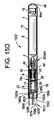
図18A~図18Eは、たばこハウジングの他の例示的な実施形態を示す。示されるように、図18A~図18Eに示す例示的な実施形態は、たばこハウジングおよびガスケット10のない不燃性喫煙装置の一部分を示す。その代わりに、ガスケット1560は、プレベイパー製剤供給貯蔵部22に隣接する。簡潔性のために、図18A~図18Eの例示的な実施形態と図15A~図15Eの例示的な実施形態の異なる部分のみを説明する。 Figures 18A-18E show other exemplary embodiments of tobacco housings. As shown, the exemplary embodiment shown in FIGS. 18A-18E shows a portion of a non-combustible smoking device without the tobacco housing and
図18Aに示すように、ガスケット1560は、プレベイパー製剤供給貯蔵部22に隣接する。気流要素1570aは、たばこハウジング1840aを通じて延在する。たばこハウジング1840aおよび気流要素1570aは、たばこハウジング1840aおよび気流要素1570がガスケット10の不存在のために長いことを除いて、たばこハウジング1540および気流要素1570とそれぞれ同じである。 As shown in FIG. 18A,
図18Bは、別の例示的な実施形態によるたばこハウジングを示す。図18Aと同様に、ガスケット1560は、たばこハウジング1840bの一方の端部を画定し、プレベイパー製剤供給貯蔵部22に隣接する。対向する端において、ガスケット1705は、たばこハウジング1840bの他方の端部を画定する。気流要素1570aは、チャネル9から、たばこハウジング1840bを通じて、マウスピース1850まで延在する。図18B~図18Eに示す実施形態において、チッピングペーパーは、たばこを含むように用いられうる。 FIG. 18B shows a tobacco housing according to another exemplary embodiment. Similar to FIG. 18A,
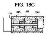
図18Cは、別の例示的な実施形態によるたばこハウジングを示す。たばこハウジング1840cは、たばこハウジング1840cがたばこハウジング1840cの中央に別のガスケット1562を含むことを除いて、図18Bに示したたばこハウジング1840bと同じである。ガスケット1562はガスケット1560と同じである。 Figure 18C shows a tobacco housing according to another exemplary embodiment.
図18Dは、別の例示的な実施形態によるたばこハウジングを示す。たばこハウジング1840dは、たばこハウジング1840dがガスケット1705の代わりにガスケット1564を含むことを除いて、図18Cに示したたばこハウジング1840cと同じである。ガスケット1564はガスケット1562および1560と同じである。 FIG. 18D shows a cigarette housing according to another exemplary embodiment.
図18Eは、別の例示的な実施形態によるたばこハウジングを示す。たばこハウジング1840eは、たばこハウジング1840eがガスケット1562の代わりにガスケット1705aを含むことを除いて、図18Cに示したたばこハウジング1840cと同じである。ガスケット1705aはガスケット1705と同じである。 FIG. 18E shows a tobacco housing according to another exemplary embodiment.
例示的な実施形態が説明されているため、これらは多くの方法で変化しうることが明らかであろう。こうした変形は、例示的な実施形態の意図する範囲から逸脱するものとして見なされるべきではなく、当業者であれば明らかであるようなこうした修正のすべては、以下の特許請求の範囲の範囲内に含めるべきであることを意図している。 While exemplary embodiments have been described, it will be apparent that these may vary in many ways. Such variations are not to be viewed as departing from the intended scope of the exemplary embodiments, and all such modifications as would be apparent to one skilled in the art are intended to be within the scope of the following claims. intended to be included.
Claims (11)
Translated fromJapaneseプレベイパー製剤材料を収容するように構成されるプレベイパー製剤貯蔵部と、
前記プレベイパー製剤貯蔵部に結合され、前記プレベイパー製剤材料の少なくとも一部分を加熱して発生したベイパーにするように、かつチャネルの第一の部分に前記発生したベイパーを提供するように構成される、発熱体と、
前記チャネルの第二の部分にあり、前記発生したベイパーを受けるように位置付けられる、たばこハウジングであって、たばこを含む、たばこハウジングと、
前記発生したベイパーの少なくとも第一の部分を前記不燃性喫煙要素の端部に向けて方向付けるための前記たばこハウジング内の少なくとも一つの気流要素と、を備え、
前記気流要素が、前記たばこハウジングの第一の端部分から前記たばこハウジングの対向する第二の端部分まで延在し、且つ、前記たばこハウジングを第一の部分と第二の部分に分離し、前記第一の部分が、前記発生したベイパーの前記第一の部分が前記たばこに晒されることを防ぐように構成される、不燃性喫煙要素。A non-combustible smoking element comprising:
a pre-vapor formulation reservoir configured to contain a pre-vapor formulation material;
An exotherm coupled to the pre-vapor formulation reservoir and configured to heat at least a portion of the pre-vapor formulation material into a generated vapor and to provide the generated vapor to a first portion of the channel. body and
a tobacco housing in a second portion of the channel and positioned to receive the generated vapor, the tobacco housing comprising tobacco;
at least one airflow element within the tobacco housing for directing at least a first portion of the generated vapor toward an end of the non-combustible smoking element;
the air flow elementextends from a first end portion of the tobacco housing to an opposing second end portion of the tobacco housing and separates the tobacco housing into a first portion and a second portion; A non-combustible smoking element, wherein said first portion is configured to prevent said first portion of said generated vapor from being exposed to said tobacco.
プレベイパー製剤材料を収容するように構成されるプレベイパー製剤貯蔵部と、
前記プレベイパー製剤貯蔵部に結合され、前記プレベイパー製剤材料の少なくとも一部分を加熱して発生したベイパーにするように、かつチャネルの第一の部分に前記発生したベイパーを提供するように構成される、発熱体と、
前記チャネルの第二の部分に延在する仕切りであって、前記仕切りが、長軸方向に延在し、前記チャネルの前記第二の部分を単一の空気流路部分とたばこ部分に区分し、前記単一の空気流路部分および前記たばこ部分が、前記発生したベイパーを受けるように位置付けられ、前記たばこ部分が、
たばこを有し、前記発生したベイパーの第一の部分を受けるように位置付けられる、たばこ要素を含み、
前記仕切りの前記位置が所望の量の発生したベイパーが、前記たばこ要素を通過することなく前記チャネルを通って流れることを可能にする、仕切りと、
内径を有し、前記長軸方向に延在するハウジングであって、前記プレベイパー製剤貯蔵部、前記発熱体、および前記仕切りを収容し、前記仕切りが、前記ハウジングに対して第一の半径方向にその内径の65パーセントの距離で、および前記ハウジングに対して対向する第二の半径方向に前記内径の35パーセントの距離で位置付けられる、ハウジングと、
を備える、不燃性喫煙要素。A non-combustible smoking element comprising:
a pre-vapor formulation reservoir configured to contain a pre-vapor formulation material;
An exotherm coupled to the pre-vapor formulation reservoir and configured to heat at least a portion of the pre-vapor formulation material into a generated vapor and to provide the generated vapor to a first portion of the channel. body and
a partition extending in a second portion of said channel, said partition extending longitudinally and dividing said second portion of said channel into a single airflow path portion and a tobacco portion; , wherein the single air channel portion and the tobacco portion are positioned to receive the generated vapor, the tobacco portion comprising:
a tobacco element having tobacco and positioned to receive a first portion of the generated vapor;
a partition, wherein said position of said partition allows a desired amount of generated vapor to flow through said channel without passing through said tobacco element;
a longitudinally extending housing having an inner diameter and containing the pre-vapor formulation reservoir, the heating element, and the partition, the partition extending in a first radial direction relative to the housing; a housing positioned at a distance of 65 percent of its inner diameter and at a distance of 35 percent of said inner diameter in a second opposite radial direction relative to said housing;
A non-combustible smoking element comprising:
請求項1~7のいずれかに記載の不燃性喫煙要素と、
前記発熱体に電力を供給するように構成される、電源と、
を備える、不燃性喫煙装置。A nonflammable smoking device,
a non-combustible smoking element according to any one of claims 1 to7 ;
a power source configured to power the heating element;
A non-combustible smoking device comprising:
Applications Claiming Priority (3)
| Application Number | Priority Date | Filing Date | Title |
|---|---|---|---|
| US15/284,897US10842193B2 (en) | 2016-10-04 | 2016-10-04 | Non-combustible smoking device and elements thereof |
| US15/284,897 | 2016-10-04 | ||
| PCT/EP2017/075254WO2018065489A1 (en) | 2016-10-04 | 2017-10-04 | Non-combustible smoking device and elements thereof |
Publications (2)
| Publication Number | Publication Date |
|---|---|
| JP2019531079A JP2019531079A (en) | 2019-10-31 |
| JP7194677B2true JP7194677B2 (en) | 2022-12-22 |
Family
ID=60009649
Family Applications (1)
| Application Number | Title | Priority Date | Filing Date |
|---|---|---|---|
| JP2019518276AActiveJP7194677B2 (en) | 2016-10-04 | 2017-10-04 | Non-combustible smoking device and elements thereof |
Country Status (12)
| Country | Link |
|---|---|
| US (3) | US10842193B2 (en) |
| EP (1) | EP3522740B1 (en) |
| JP (1) | JP7194677B2 (en) |
| KR (1) | KR102578973B1 (en) |
| CN (1) | CN109688853B (en) |
| CA (1) | CA3032910A1 (en) |
| ES (1) | ES2865349T3 (en) |
| IL (1) | IL265728A (en) |
| MX (1) | MX2019003641A (en) |
| PL (1) | PL3522740T3 (en) |
| RU (1) | RU2749517C2 (en) |
| WO (1) | WO2018065489A1 (en) |
Families Citing this family (24)
| Publication number | Priority date | Publication date | Assignee | Title |
|---|---|---|---|---|
| IL279264B (en)* | 2015-05-06 | 2022-09-01 | Altria Client Services Llc | A non-flammable smoking device and its components |
| US10455863B2 (en)* | 2016-03-03 | 2019-10-29 | Altria Client Services Llc | Cartridge for electronic vaping device |
| US10433580B2 (en) | 2016-03-03 | 2019-10-08 | Altria Client Services Llc | Methods to add menthol, botanic materials, and/or non-botanic materials to a cartridge, and/or an electronic vaping device including the cartridge |
| US10368580B2 (en) | 2016-03-08 | 2019-08-06 | Altria Client Services Llc | Combined cartridge for electronic vaping device |
| US10357060B2 (en) | 2016-03-11 | 2019-07-23 | Altria Client Services Llc | E-vaping device cartridge holder |
| US10368581B2 (en) | 2016-03-11 | 2019-08-06 | Altria Client Services Llc | Multiple dispersion generator e-vaping device |
| WO2017185051A1 (en) | 2016-04-22 | 2017-10-26 | Pax Labs, Inc. | Aerosol devices having compartmentalized materials |
| US10881139B2 (en)* | 2016-07-07 | 2021-01-05 | Altria Client Services Llc | Non-combustible vaping element with tobacco insert |
| US10433585B2 (en)* | 2016-12-28 | 2019-10-08 | Altria Client Services Llc | Non-combustible smoking systems, devices and elements thereof |
| KR102627051B1 (en)* | 2017-10-13 | 2024-01-19 | 필립모리스 프로덕츠 에스.에이. | Aerosol-generating articles having cavities equipped with particulate aerosol modifying material |
| WO2019237052A1 (en) | 2018-06-07 | 2019-12-12 | Juul Labs, Inc. | Cartridges for vaporizer devices |
| CN208434718U (en)* | 2018-06-22 | 2019-01-29 | 湖南中烟工业有限责任公司 | An electronic cigarette vaporizer and the electronic cigarette |
| CN119632302A (en) | 2018-07-31 | 2025-03-18 | 尤尔实验室有限公司 | Cartridge-based heat-without-burn vaporizer |
| KR20250048483A (en) | 2018-10-08 | 2025-04-08 | 쥴 랩스, 인크. | Heating element |
| JP7502015B2 (en) | 2018-11-08 | 2024-06-18 | ジュール・ラブズ・インコーポレイテッド | Vaporizer device with one or more heating elements |
| WO2020205561A1 (en) | 2019-03-29 | 2020-10-08 | Juul Labs, Inc. | Cartridges for vaporizer devices |
| US11491299B2 (en) | 2019-04-20 | 2022-11-08 | Flat Planet Limited | Dual convection and conduction oven for flower stick |
| US11877596B2 (en)* | 2019-05-13 | 2024-01-23 | Tuanfang Liu | Electronic cigarette |
| EP4531148A3 (en) | 2019-09-03 | 2025-06-11 | Juul Labs, Inc. | Fuel cell powered vaporizer device |
| WO2021105184A1 (en)* | 2019-11-29 | 2021-06-03 | Jt International Sa | Electronic cigarette |
| GB202011517D0 (en)* | 2020-07-24 | 2020-09-09 | Nicoventures Trading Ltd | Aerosol provision system |
| MX2023001254A (en)* | 2020-07-29 | 2023-03-03 | Acetate Int Llc | Catalyst introduction methods for accelerated deacetylation of cellulose esters. |
| EP4195959A4 (en)* | 2020-07-31 | 2024-12-18 | Flat Planet Limited | DOUBLE CONVECTION AND CONDUCTION OVEN FOR FLOWER STICK |
| US12004560B1 (en)* | 2023-02-21 | 2024-06-11 | Dan Beal | Smoking storage device |
Citations (4)
| Publication number | Priority date | Publication date | Assignee | Title |
|---|---|---|---|---|
| JP2015512617A (en) | 2012-01-31 | 2015-04-30 | アルトリア クライアント サービシーズ インコーポレイ | Electronic cigarette |
| WO2016062777A1 (en) | 2014-10-22 | 2016-04-28 | British American Tobacco (Investments) Limited | Inhalator and cartridge thereof |
| US20160120224A1 (en) | 2014-10-29 | 2016-05-05 | Munmaya K. Mishra | E-vaping cartridge |
| WO2016121143A1 (en) | 2015-01-26 | 2016-08-04 | 日本たばこ産業株式会社 | Non-combustible flavor inhaler, flavor source unit, and method for manufacturing non-combustible flavor inhaler member |
Family Cites Families (102)
| Publication number | Priority date | Publication date | Assignee | Title |
|---|---|---|---|---|
| US4393884A (en) | 1981-09-25 | 1983-07-19 | Jacobs Allen W | Demand inhaler for oral administration of tobacco, tobacco-like, or other substances |
| US5020548A (en) | 1985-08-26 | 1991-06-04 | R. J. Reynolds Tobacco Company | Smoking article with improved fuel element |
| US5067499A (en) | 1984-09-14 | 1991-11-26 | R. J. Reynolds Tobacco Company | Smoking article |
| US5042509A (en) | 1984-09-14 | 1991-08-27 | R. J. Reynolds Tobacco Company | Method for making aerosol generating cartridge |
| US4793365A (en) | 1984-09-14 | 1988-12-27 | R. J. Reynolds Tobacco Company | Smoking article |
| US4854331A (en) | 1984-09-14 | 1989-08-08 | R. J. Reynolds Tobacco Company | Smoking article |
| US5033483A (en) | 1985-10-28 | 1991-07-23 | R. J. Reynolds Tobacco Company | Smoking article with tobacco jacket |
| US4756318A (en) | 1985-10-28 | 1988-07-12 | R. J. Reynolds Tobacco Company | Smoking article with tobacco jacket |
| US5060666A (en) | 1985-10-28 | 1991-10-29 | R. J. Reynolds Tobacco Company | Smoking article with tobacco jacket |
| US4917128A (en) | 1985-10-28 | 1990-04-17 | R. J. Reynolds Tobacco Co. | Cigarette |
| US4708151A (en) | 1986-03-14 | 1987-11-24 | R. J. Reynolds Tobacco Company | Pipe with replaceable cartridge |
| IL83826A (en) | 1987-09-08 | 1991-03-10 | Inventor S Funding Corp Ltd | Plastic mouthpiece for simulated smoking |
| US4947874A (en) | 1988-09-08 | 1990-08-14 | R. J. Reynolds Tobacco Company | Smoking articles utilizing electrical energy |
| DE3908160A1 (en) | 1989-03-13 | 1990-09-27 | Bat Cigarettenfab Gmbh | Smokable article |
| US4961438A (en) | 1989-04-03 | 1990-10-09 | Brown & Williamson Tobacco Corporation | Smoking device |
| US5060671A (en) | 1989-12-01 | 1991-10-29 | Philip Morris Incorporated | Flavor generating article |
| GB9102658D0 (en) | 1991-02-07 | 1991-03-27 | British American Tobacco Co | Improvements relating to smoking articles |
| US5065776A (en) | 1990-08-29 | 1991-11-19 | R. J. Reynolds Tobacco Company | Cigarette with tobacco/glass fuel wrapper |
| US5203355A (en) | 1991-02-14 | 1993-04-20 | R. J. Reynolds Tobacco Company | Cigarette with cellulosic substrate |
| US5240016A (en) | 1991-04-19 | 1993-08-31 | Philip Morris Incorporated | Thermally releasable gel-based flavor source for smoking articles |
| US5159942A (en) | 1991-06-04 | 1992-11-03 | R. J. Reynolds Tobacco Company | Process for providing smokable material for a cigarette |
| US5235992A (en) | 1991-06-28 | 1993-08-17 | R. J. Reynolds Tobacco Company | Processes for producing flavor substances from tobacco and smoking articles made therewith |
| US5293883A (en) | 1992-05-04 | 1994-03-15 | Edwards Patrica T | Non-combustible anti-smoking device with nicotine impregnated mouthpiece |
| US5595706A (en) | 1994-12-29 | 1997-01-21 | Philip Morris Incorporated | Aluminum containing iron-base alloys useful as electrical resistance heating elements |
| US6532965B1 (en) | 2001-10-24 | 2003-03-18 | Brown & Williamson Tobacco Corporation | Smoking article using steam as an aerosol-generating source |
| US20060272659A1 (en)* | 2005-06-06 | 2006-12-07 | Gerd Kobal | Modular smoking article and method of use |
| US20070215167A1 (en) | 2006-03-16 | 2007-09-20 | Evon Llewellyn Crooks | Smoking article |
| WO2007078273A1 (en)* | 2005-12-22 | 2007-07-12 | Augite Incorporation | No-tar electronic smoking utensils |
| US20070267033A1 (en)* | 2006-02-09 | 2007-11-22 | Philip Morris Usa Inc. | Gamma cyclodextrin flavoring-release additives |
| US7726320B2 (en) | 2006-10-18 | 2010-06-01 | R. J. Reynolds Tobacco Company | Tobacco-containing smoking article |
| US7845359B2 (en) | 2007-03-22 | 2010-12-07 | Pierre Denain | Artificial smoke cigarette |
| CN201127292Y (en) | 2007-12-21 | 2008-10-08 | 中国烟草总公司郑州烟草研究院 | Smokeless type electric cigarette |
| TW201023769A (en) | 2008-10-23 | 2010-07-01 | Japan Tobacco Inc | Non-burning type flavor inhalation article |
| AT507187B1 (en) | 2008-10-23 | 2010-03-15 | Helmut Dr Buchberger | INHALER |
| GB0918129D0 (en) | 2009-10-16 | 2009-12-02 | British American Tobacco Co | Control of puff profile |
| WO2011146264A2 (en) | 2010-05-21 | 2011-11-24 | Global Vapor Trademarks Incorporated | Method for preparing tobacco extract for electronic smoking devices |
| CN201830900U (en) | 2010-06-09 | 2011-05-18 | 李永海 | Tobacco juice atomization device for electronic cigarette |
| US20120199146A1 (en) | 2011-02-09 | 2012-08-09 | Bill Marangos | Electronic cigarette |
| US9078473B2 (en) | 2011-08-09 | 2015-07-14 | R.J. Reynolds Tobacco Company | Smoking articles and use thereof for yielding inhalation materials |
| US20140202476A1 (en)* | 2011-09-06 | 2014-07-24 | British American Tobacco (Investments) Limited | Heating smokeable material |
| HUE045286T2 (en) | 2011-09-28 | 2019-12-30 | Philip Morris Products Sa | Permeable Electric Heat Resistant Film for Evaporation of Liquids from Single Use Nozzles with Evaporator Diaphragm |
| US9351522B2 (en) | 2011-09-29 | 2016-05-31 | Robert Safari | Cartomizer e-cigarette |
| TW201340893A (en) | 2011-12-20 | 2013-10-16 | British American Tobacco Co | Smoking articles, and other flow delivery articles |
| GB2500957A (en) | 2011-12-23 | 2013-10-09 | Qiuming Liu | Electronic cigarette suction nozzle |
| JP5807768B2 (en) | 2011-12-23 | 2015-11-10 | 恵州市吉瑞科技有限公司深▲せん▼分公司 | Electronic cigarette suction nozzle |
| WO2013097158A1 (en)* | 2011-12-29 | 2013-07-04 | Liu Qiuming | Electronic cigarette with solid tobacco tar |
| AR089602A1 (en) | 2011-12-30 | 2014-09-03 | Philip Morris Products Sa | AEROSOL GENERATOR ARTICLE FOR USE WITH AN AEROSOL GENERATOR DEVICE |
| US9078474B2 (en) | 2012-01-30 | 2015-07-14 | Spencer Thompson | Cartomizer for electronic cigarettes |
| US20130255675A1 (en) | 2012-04-01 | 2013-10-03 | Huizhou Kimree Technology Co., Ltd. | Electronic Cigarette and Mouthpiece Part Thereof |
| US9101729B2 (en) | 2012-06-05 | 2015-08-11 | Huizou Kimree Technology Co., Ltd., Shenzhen Branch | Electronic cigarette and inhaling shell thereof |
| US10004259B2 (en) | 2012-06-28 | 2018-06-26 | Rai Strategic Holdings, Inc. | Reservoir and heater system for controllable delivery of multiple aerosolizable materials in an electronic smoking article |
| CN102813278B (en) | 2012-08-09 | 2017-03-15 | 深圳瀚星翔科技有限公司 | A kind of mixed type electronic cigarette tobacco liquid |
| US8881737B2 (en) | 2012-09-04 | 2014-11-11 | R.J. Reynolds Tobacco Company | Electronic smoking article comprising one or more microheaters |
| US10117460B2 (en) | 2012-10-08 | 2018-11-06 | Rai Strategic Holdings, Inc. | Electronic smoking article and associated method |
| US9854841B2 (en) | 2012-10-08 | 2018-01-02 | Rai Strategic Holdings, Inc. | Electronic smoking article and associated method |
| US10154691B2 (en) | 2012-11-26 | 2018-12-18 | Nu Mark Innovations Ltd. | Bonding for an electronic cigarette cartridge |
| US20140166028A1 (en) | 2012-12-14 | 2014-06-19 | Richard C. Fuisz | Enhanced Delivery of Nicotine, THC, Tobacco, Cannabidiol or Base Alkaloid from an Electronic Cigarette or Other Vapor or Smoke Producing Device Through Use of an Absorption Conditioning Unit |
| US9943107B2 (en) | 2012-12-17 | 2018-04-17 | Sis Resources, Ltd. | Cartomizer flavor enhancement |
| US20140182612A1 (en)* | 2012-12-28 | 2014-07-03 | Shenzhen Smoore Technology Limited | Electronic atomizing inhalation device |
| CN112353001B (en) | 2013-01-24 | 2025-02-25 | 富特姆投资有限公司 | Methods, compositions and devices for functionalization of aerosols for non-combustible smoking articles |
| GB2511305A (en) | 2013-02-27 | 2014-09-03 | British American Tobacco Co | A smoking device and a component for a smoking device |
| GB2511303A (en) | 2013-02-27 | 2014-09-03 | British American Tobacco Co | Smoking apparatus |
| US10031183B2 (en) | 2013-03-07 | 2018-07-24 | Rai Strategic Holdings, Inc. | Spent cartridge detection method and system for an electronic smoking article |
| US20140261486A1 (en) | 2013-03-12 | 2014-09-18 | R.J. Reynolds Tobacco Company | Electronic smoking article having a vapor-enhancing apparatus and associated method |
| US9877508B2 (en) | 2013-03-15 | 2018-01-30 | Altria Client Services Llc | Electronic cigarette |
| US9723876B2 (en) | 2013-03-15 | 2017-08-08 | Altria Client Services Llc | Electronic smoking article |
| US9402421B2 (en)* | 2013-03-29 | 2016-08-02 | Huizhou Kimree Technology Co., Ltd., Shenzhen Branch | Electronic cigarette |
| CN103393222B (en)* | 2013-08-16 | 2015-09-16 | 湖北中烟工业有限责任公司 | There is the nicotine smoke fog normal temperature cigarette of tobacco flavor |
| GB2513627B (en) | 2013-05-02 | 2018-02-07 | Jt Int Sa | Vaporisable material plug |
| US20140355969A1 (en) | 2013-05-28 | 2014-12-04 | Sis Resources, Ltd. | One-way valve for atomizer section in electronic cigarettes |
| CN105473012B (en)* | 2013-06-14 | 2020-06-19 | 尤尔实验室有限公司 | Multiple heating elements with separate vaporizable materials in electronic vaporization equipment |
| ITMO20130192A1 (en) | 2013-06-28 | 2014-12-29 | Damco S R L | KIT FOR ELECTRONIC CIGARETTES |
| US10390562B2 (en) | 2013-07-23 | 2019-08-27 | Altria Client Services Llc | Electronic smoking article |
| CN105592734A (en) | 2013-07-24 | 2016-05-18 | 奥驰亚客户服务有限责任公司 | Electronic smoking devices with alternative airflow paths |
| US9877511B2 (en)* | 2013-07-24 | 2018-01-30 | Altria Client Services Llc | Electronic smoking article |
| US9955727B2 (en) | 2013-07-24 | 2018-05-01 | Nu Mark Innovations Ltd. | Solid core electronic cigarette |
| US10278422B2 (en) | 2013-08-26 | 2019-05-07 | Altria Client Services Llc | Electronic cigarette with reduced energy consumption and environmental impact |
| WO2015046385A1 (en) | 2013-09-30 | 2015-04-02 | 日本たばこ産業株式会社 | Non-combustion type flavor aspirator and capsule unit |
| CN103519351B (en)* | 2013-10-31 | 2017-02-15 | 红塔烟草(集团)有限责任公司 | Electrical heating cigarette |
| US10292424B2 (en) | 2013-10-31 | 2019-05-21 | Rai Strategic Holdings, Inc. | Aerosol delivery device including a pressure-based aerosol delivery mechanism |
| US20150128968A1 (en) | 2013-11-11 | 2015-05-14 | R.J. Reynolds Tobacco Company | Mouthpiece for smoking article |
| WO2015073975A1 (en) | 2013-11-15 | 2015-05-21 | VMR Products, LLC | Vaporizer with cover sleeve |
| CN105792687A (en) | 2013-11-15 | 2016-07-20 | Jj206有限责任公司 | Systems and methods for a vaporization device and product usage control and documentation |
| US20150164147A1 (en) | 2013-12-16 | 2015-06-18 | VMR Products, LLC | Cartridge for a vaporizor |
| CN203618787U (en) | 2013-12-30 | 2014-06-04 | 林光榕 | Electronic cigarette |
| DE202014001718U1 (en)* | 2014-02-27 | 2015-05-28 | Xeo Holding GmbH | smoking device |
| CN103815547B (en)* | 2014-03-16 | 2017-01-04 | 云南烟草科学研究院 | A kind of heater heating Medicated cigarette |
| US9010335B1 (en) | 2014-05-13 | 2015-04-21 | Njoy, Inc. | Mechanisms for vaporizing devices |
| US20150335070A1 (en) | 2014-05-20 | 2015-11-26 | R.J. Reynolds Tobacco Company | Electrically-powered aerosol delivery system |
| US20160073695A1 (en)* | 2014-05-20 | 2016-03-17 | R. J. Reynolds Tobacco Company | Electrically-powered aerosol delivery system |
| CN204146321U (en) | 2014-06-11 | 2015-02-11 | 湖南中烟工业有限责任公司 | Atomizer and there is the electronic cigarette of this atomizer |
| GB201500582D0 (en) | 2015-01-14 | 2015-02-25 | British American Tobacco Co | Apparatus for heating or cooling a material contained therein |
| WO2016004576A1 (en)* | 2014-07-08 | 2016-01-14 | 深圳市康尔科技有限公司 | Electronic cigarette allowing liquid to be injected from top and heating assembly to be replaced at bottom |
| CN104188107B (en)* | 2014-07-30 | 2019-01-08 | 深圳市合元科技有限公司 | The baking-type smoking apparatus of controllable tobacco heating amount |
| GB2529201A (en) | 2014-08-13 | 2016-02-17 | Batmark Ltd | Device and method |
| US11013264B2 (en) | 2014-11-19 | 2021-05-25 | Fontem Holdings 4 B.V. | Method, composition and apparatus for functionalization of aerosols from non combustible smoking articles |
| CN104397878B (en) | 2014-11-21 | 2017-10-27 | 黄金珍 | Heat non-combustion-type electronic smoke atomizer and electronic cigarette |
| GB201503411D0 (en)* | 2015-02-27 | 2015-04-15 | British American Tobacco Co | Apparatus and method for generating an inhalable medium, and a cartridge for use therewith |
| EP3261467B1 (en) | 2015-02-27 | 2022-03-30 | Nicoventures Trading Limited | Cartridge, components and methods for generating an inhalable medium |
| CN205072067U (en)* | 2015-07-27 | 2016-03-09 | 湖北中烟工业有限责任公司 | Electrical heating smoking device |
| CN105595431B (en)* | 2015-12-31 | 2019-05-21 | 山东中烟工业有限责任公司 | A kind of non-burning tobacco device of primary and secondary cooking-pot type heating |
| WO2018037562A1 (en)* | 2016-08-26 | 2018-03-01 | 日本たばこ産業株式会社 | Non-combustion flavor inhaler |
- 2016
- 2016-10-04USUS15/284,897patent/US10842193B2/enactiveActive
- 2017
- 2017-10-04PLPL17778303Tpatent/PL3522740T3/enunknown
- 2017-10-04KRKR1020197006881Apatent/KR102578973B1/enactiveActive
- 2017-10-04MXMX2019003641Apatent/MX2019003641A/enunknown
- 2017-10-04ESES17778303Tpatent/ES2865349T3/enactiveActive
- 2017-10-04RURU2019111710Apatent/RU2749517C2/enactive
- 2017-10-04CACA3032910Apatent/CA3032910A1/ennot_activeAbandoned
- 2017-10-04EPEP17778303.2Apatent/EP3522740B1/enactiveActive
- 2017-10-04WOPCT/EP2017/075254patent/WO2018065489A1/ennot_activeCeased
- 2017-10-04CNCN201780055807.7Apatent/CN109688853B/enactiveActive
- 2017-10-04JPJP2019518276Apatent/JP7194677B2/enactiveActive
- 2019
- 2019-03-31ILIL265728Apatent/IL265728A/enunknown
- 2020
- 2020-10-19USUS17/074,067patent/US12178243B2/enactiveActive
- 2024
- 2024-12-05USUS18/969,406patent/US20250089767A1/enactivePending
Patent Citations (4)
| Publication number | Priority date | Publication date | Assignee | Title |
|---|---|---|---|---|
| JP2015512617A (en) | 2012-01-31 | 2015-04-30 | アルトリア クライアント サービシーズ インコーポレイ | Electronic cigarette |
| WO2016062777A1 (en) | 2014-10-22 | 2016-04-28 | British American Tobacco (Investments) Limited | Inhalator and cartridge thereof |
| US20160120224A1 (en) | 2014-10-29 | 2016-05-05 | Munmaya K. Mishra | E-vaping cartridge |
| WO2016121143A1 (en) | 2015-01-26 | 2016-08-04 | 日本たばこ産業株式会社 | Non-combustible flavor inhaler, flavor source unit, and method for manufacturing non-combustible flavor inhaler member |
Also Published As
| Publication number | Publication date |
|---|---|
| PL3522740T3 (en) | 2021-08-23 |
| EP3522740B1 (en) | 2021-03-24 |
| US12178243B2 (en) | 2024-12-31 |
| RU2749517C2 (en) | 2021-06-11 |
| IL265728A (en) | 2019-05-30 |
| RU2019111710A (en) | 2020-11-06 |
| KR102578973B1 (en) | 2023-09-15 |
| KR20190055800A (en) | 2019-05-23 |
| ES2865349T3 (en) | 2021-10-15 |
| RU2019111710A3 (en) | 2020-11-26 |
| US20210030061A1 (en) | 2021-02-04 |
| EP3522740A1 (en) | 2019-08-14 |
| US20250089767A1 (en) | 2025-03-20 |
| CN109688853A (en) | 2019-04-26 |
| US20180092400A1 (en) | 2018-04-05 |
| MX2019003641A (en) | 2019-08-12 |
| WO2018065489A1 (en) | 2018-04-12 |
| CA3032910A1 (en) | 2018-04-12 |
| JP2019531079A (en) | 2019-10-31 |
| CN109688853B (en) | 2021-10-29 |
| US10842193B2 (en) | 2020-11-24 |
Similar Documents
| Publication | Publication Date | Title |
|---|---|---|
| JP7194677B2 (en) | Non-combustible smoking device and elements thereof | |
| JP7288495B2 (en) | Non-combustible smoking device and elements thereof | |
| JP7175893B2 (en) | Non-combustible smoking systems, devices and elements thereof | |
| CN107635419B (en) | Non-combustion smoking device and components thereof |
Legal Events
| Date | Code | Title | Description |
|---|---|---|---|
| A521 | Request for written amendment filed | Free format text:JAPANESE INTERMEDIATE CODE: A523 Effective date:20190411 | |
| A621 | Written request for application examination | Free format text:JAPANESE INTERMEDIATE CODE: A621 Effective date:20200911 | |
| A977 | Report on retrieval | Free format text:JAPANESE INTERMEDIATE CODE: A971007 Effective date:20210928 | |
| A131 | Notification of reasons for refusal | Free format text:JAPANESE INTERMEDIATE CODE: A131 Effective date:20211004 | |
| A601 | Written request for extension of time | Free format text:JAPANESE INTERMEDIATE CODE: A601 Effective date:20211228 | |
| A521 | Request for written amendment filed | Free format text:JAPANESE INTERMEDIATE CODE: A523 Effective date:20220121 | |
| A02 | Decision of refusal | Free format text:JAPANESE INTERMEDIATE CODE: A02 Effective date:20220511 | |
| A521 | Request for written amendment filed | Free format text:JAPANESE INTERMEDIATE CODE: A523 Effective date:20220824 | |
| C60 | Trial request (containing other claim documents, opposition documents) | Free format text:JAPANESE INTERMEDIATE CODE: C60 Effective date:20220824 | |
| A911 | Transfer to examiner for re-examination before appeal (zenchi) | Free format text:JAPANESE INTERMEDIATE CODE: A911 Effective date:20220901 | |
| C21 | Notice of transfer of a case for reconsideration by examiners before appeal proceedings | Free format text:JAPANESE INTERMEDIATE CODE: C21 Effective date:20220905 | |
| TRDD | Decision of grant or rejection written | ||
| A01 | Written decision to grant a patent or to grant a registration (utility model) | Free format text:JAPANESE INTERMEDIATE CODE: A01 Effective date:20221116 | |
| A61 | First payment of annual fees (during grant procedure) | Free format text:JAPANESE INTERMEDIATE CODE: A61 Effective date:20221212 | |
| R150 | Certificate of patent or registration of utility model | Ref document number:7194677 Country of ref document:JP Free format text:JAPANESE INTERMEDIATE CODE: R150 |