JP7194666B2 - Display device - Google Patents
Display deviceDownload PDFInfo
- Publication number
- JP7194666B2 JP7194666B2JP2019208461AJP2019208461AJP7194666B2JP 7194666 B2JP7194666 B2JP 7194666B2JP 2019208461 AJP2019208461 AJP 2019208461AJP 2019208461 AJP2019208461 AJP 2019208461AJP 7194666 B2JP7194666 B2JP 7194666B2
- Authority
- JP
- Japan
- Prior art keywords
- display
- display unit
- touch panel
- display device
- detection sensitivity
- Prior art date
- Legal status (The legal status is an assumption and is not a legal conclusion. Google has not performed a legal analysis and makes no representation as to the accuracy of the status listed.)
- Active
Links
Images


Classifications
- G—PHYSICS
- G06—COMPUTING OR CALCULATING; COUNTING
- G06F—ELECTRIC DIGITAL DATA PROCESSING
- G06F3/00—Input arrangements for transferring data to be processed into a form capable of being handled by the computer; Output arrangements for transferring data from processing unit to output unit, e.g. interface arrangements
- G06F3/01—Input arrangements or combined input and output arrangements for interaction between user and computer
- G06F3/016—Input arrangements with force or tactile feedback as computer generated output to the user
- G—PHYSICS
- G06—COMPUTING OR CALCULATING; COUNTING
- G06F—ELECTRIC DIGITAL DATA PROCESSING
- G06F3/00—Input arrangements for transferring data to be processed into a form capable of being handled by the computer; Output arrangements for transferring data from processing unit to output unit, e.g. interface arrangements
- G06F3/01—Input arrangements or combined input and output arrangements for interaction between user and computer
- G06F3/03—Arrangements for converting the position or the displacement of a member into a coded form
- G06F3/033—Pointing devices displaced or positioned by the user, e.g. mice, trackballs, pens or joysticks; Accessories therefor
- G06F3/0354—Pointing devices displaced or positioned by the user, e.g. mice, trackballs, pens or joysticks; Accessories therefor with detection of 2D relative movements between the device, or an operating part thereof, and a plane or surface, e.g. 2D mice, trackballs, pens or pucks
- G06F3/03547—Touch pads, in which fingers can move on a surface
- G—PHYSICS
- G06—COMPUTING OR CALCULATING; COUNTING
- G06F—ELECTRIC DIGITAL DATA PROCESSING
- G06F3/00—Input arrangements for transferring data to be processed into a form capable of being handled by the computer; Output arrangements for transferring data from processing unit to output unit, e.g. interface arrangements
- G06F3/01—Input arrangements or combined input and output arrangements for interaction between user and computer
- G06F3/03—Arrangements for converting the position or the displacement of a member into a coded form
- G06F3/041—Digitisers, e.g. for touch screens or touch pads, characterised by the transducing means
- G06F3/0412—Digitisers structurally integrated in a display
- B—PERFORMING OPERATIONS; TRANSPORTING
- B60—VEHICLES IN GENERAL
- B60K—ARRANGEMENT OR MOUNTING OF PROPULSION UNITS OR OF TRANSMISSIONS IN VEHICLES; ARRANGEMENT OR MOUNTING OF PLURAL DIVERSE PRIME-MOVERS IN VEHICLES; AUXILIARY DRIVES FOR VEHICLES; INSTRUMENTATION OR DASHBOARDS FOR VEHICLES; ARRANGEMENTS IN CONNECTION WITH COOLING, AIR INTAKE, GAS EXHAUST OR FUEL SUPPLY OF PROPULSION UNITS IN VEHICLES
- B60K35/00—Instruments specially adapted for vehicles; Arrangement of instruments in or on vehicles
- B60K35/10—Input arrangements, i.e. from user to vehicle, associated with vehicle functions or specially adapted therefor
- B—PERFORMING OPERATIONS; TRANSPORTING
- B60—VEHICLES IN GENERAL
- B60K—ARRANGEMENT OR MOUNTING OF PROPULSION UNITS OR OF TRANSMISSIONS IN VEHICLES; ARRANGEMENT OR MOUNTING OF PLURAL DIVERSE PRIME-MOVERS IN VEHICLES; AUXILIARY DRIVES FOR VEHICLES; INSTRUMENTATION OR DASHBOARDS FOR VEHICLES; ARRANGEMENTS IN CONNECTION WITH COOLING, AIR INTAKE, GAS EXHAUST OR FUEL SUPPLY OF PROPULSION UNITS IN VEHICLES
- B60K35/00—Instruments specially adapted for vehicles; Arrangement of instruments in or on vehicles
- B60K35/20—Output arrangements, i.e. from vehicle to user, associated with vehicle functions or specially adapted therefor
- B60K35/21—Output arrangements, i.e. from vehicle to user, associated with vehicle functions or specially adapted therefor using visual output, e.g. blinking lights or matrix displays
- B60K35/22—Display screens
- B—PERFORMING OPERATIONS; TRANSPORTING
- B60—VEHICLES IN GENERAL
- B60K—ARRANGEMENT OR MOUNTING OF PROPULSION UNITS OR OF TRANSMISSIONS IN VEHICLES; ARRANGEMENT OR MOUNTING OF PLURAL DIVERSE PRIME-MOVERS IN VEHICLES; AUXILIARY DRIVES FOR VEHICLES; INSTRUMENTATION OR DASHBOARDS FOR VEHICLES; ARRANGEMENTS IN CONNECTION WITH COOLING, AIR INTAKE, GAS EXHAUST OR FUEL SUPPLY OF PROPULSION UNITS IN VEHICLES
- B60K35/00—Instruments specially adapted for vehicles; Arrangement of instruments in or on vehicles
- B60K35/20—Output arrangements, i.e. from vehicle to user, associated with vehicle functions or specially adapted therefor
- B60K35/25—Output arrangements, i.e. from vehicle to user, associated with vehicle functions or specially adapted therefor using haptic output
- B—PERFORMING OPERATIONS; TRANSPORTING
- B60—VEHICLES IN GENERAL
- B60K—ARRANGEMENT OR MOUNTING OF PROPULSION UNITS OR OF TRANSMISSIONS IN VEHICLES; ARRANGEMENT OR MOUNTING OF PLURAL DIVERSE PRIME-MOVERS IN VEHICLES; AUXILIARY DRIVES FOR VEHICLES; INSTRUMENTATION OR DASHBOARDS FOR VEHICLES; ARRANGEMENTS IN CONNECTION WITH COOLING, AIR INTAKE, GAS EXHAUST OR FUEL SUPPLY OF PROPULSION UNITS IN VEHICLES
- B60K35/00—Instruments specially adapted for vehicles; Arrangement of instruments in or on vehicles
- B60K35/65—Instruments specially adapted for specific vehicle types or users, e.g. for left- or right-hand drive
- G—PHYSICS
- G02—OPTICS
- G02F—OPTICAL DEVICES OR ARRANGEMENTS FOR THE CONTROL OF LIGHT BY MODIFICATION OF THE OPTICAL PROPERTIES OF THE MEDIA OF THE ELEMENTS INVOLVED THEREIN; NON-LINEAR OPTICS; FREQUENCY-CHANGING OF LIGHT; OPTICAL LOGIC ELEMENTS; OPTICAL ANALOGUE/DIGITAL CONVERTERS
- G02F1/00—Devices or arrangements for the control of the intensity, colour, phase, polarisation or direction of light arriving from an independent light source, e.g. switching, gating or modulating; Non-linear optics
- G02F1/01—Devices or arrangements for the control of the intensity, colour, phase, polarisation or direction of light arriving from an independent light source, e.g. switching, gating or modulating; Non-linear optics for the control of the intensity, phase, polarisation or colour
- G02F1/13—Devices or arrangements for the control of the intensity, colour, phase, polarisation or direction of light arriving from an independent light source, e.g. switching, gating or modulating; Non-linear optics for the control of the intensity, phase, polarisation or colour based on liquid crystals, e.g. single liquid crystal display cells
- G02F1/133—Constructional arrangements; Operation of liquid crystal cells; Circuit arrangements
- G02F1/1333—Constructional arrangements; Manufacturing methods
- G02F1/13338—Input devices, e.g. touch panels
- G—PHYSICS
- G05—CONTROLLING; REGULATING
- G05G—CONTROL DEVICES OR SYSTEMS INSOFAR AS CHARACTERISED BY MECHANICAL FEATURES ONLY
- G05G5/00—Means for preventing, limiting or returning the movements of parts of a control mechanism, e.g. locking controlling member
- G05G5/03—Means for enhancing the operator's awareness of arrival of the controlling member at a command or datum position; Providing feel, e.g. means for creating a counterforce
- G—PHYSICS
- G06—COMPUTING OR CALCULATING; COUNTING
- G06F—ELECTRIC DIGITAL DATA PROCESSING
- G06F3/00—Input arrangements for transferring data to be processed into a form capable of being handled by the computer; Output arrangements for transferring data from processing unit to output unit, e.g. interface arrangements
- G06F3/01—Input arrangements or combined input and output arrangements for interaction between user and computer
- G06F3/03—Arrangements for converting the position or the displacement of a member into a coded form
- G06F3/041—Digitisers, e.g. for touch screens or touch pads, characterised by the transducing means
- G06F3/0416—Control or interface arrangements specially adapted for digitisers
- G06F3/0418—Control or interface arrangements specially adapted for digitisers for error correction or compensation, e.g. based on parallax, calibration or alignment
- G—PHYSICS
- G06—COMPUTING OR CALCULATING; COUNTING
- G06F—ELECTRIC DIGITAL DATA PROCESSING
- G06F3/00—Input arrangements for transferring data to be processed into a form capable of being handled by the computer; Output arrangements for transferring data from processing unit to output unit, e.g. interface arrangements
- G06F3/01—Input arrangements or combined input and output arrangements for interaction between user and computer
- G06F3/03—Arrangements for converting the position or the displacement of a member into a coded form
- G06F3/041—Digitisers, e.g. for touch screens or touch pads, characterised by the transducing means
- G06F3/044—Digitisers, e.g. for touch screens or touch pads, characterised by the transducing means by capacitive means
- G06F3/0445—Digitisers, e.g. for touch screens or touch pads, characterised by the transducing means by capacitive means using two or more layers of sensing electrodes, e.g. using two layers of electrodes separated by a dielectric layer
- H—ELECTRICITY
- H03—ELECTRONIC CIRCUITRY
- H03K—PULSE TECHNIQUE
- H03K17/00—Electronic switching or gating, i.e. not by contact-making and –breaking
- H03K17/94—Electronic switching or gating, i.e. not by contact-making and –breaking characterised by the way in which the control signals are generated
- H03K17/965—Switches controlled by moving an element forming part of the switch
- H03K17/975—Switches controlled by moving an element forming part of the switch using a capacitive movable element
- B—PERFORMING OPERATIONS; TRANSPORTING
- B60—VEHICLES IN GENERAL
- B60K—ARRANGEMENT OR MOUNTING OF PROPULSION UNITS OR OF TRANSMISSIONS IN VEHICLES; ARRANGEMENT OR MOUNTING OF PLURAL DIVERSE PRIME-MOVERS IN VEHICLES; AUXILIARY DRIVES FOR VEHICLES; INSTRUMENTATION OR DASHBOARDS FOR VEHICLES; ARRANGEMENTS IN CONNECTION WITH COOLING, AIR INTAKE, GAS EXHAUST OR FUEL SUPPLY OF PROPULSION UNITS IN VEHICLES
- B60K2360/00—Indexing scheme associated with groups B60K35/00 or B60K37/00 relating to details of instruments or dashboards
- B60K2360/143—Touch sensitive instrument input devices
- B60K2360/1438—Touch screens
- B—PERFORMING OPERATIONS; TRANSPORTING
- B60—VEHICLES IN GENERAL
- B60K—ARRANGEMENT OR MOUNTING OF PROPULSION UNITS OR OF TRANSMISSIONS IN VEHICLES; ARRANGEMENT OR MOUNTING OF PLURAL DIVERSE PRIME-MOVERS IN VEHICLES; AUXILIARY DRIVES FOR VEHICLES; INSTRUMENTATION OR DASHBOARDS FOR VEHICLES; ARRANGEMENTS IN CONNECTION WITH COOLING, AIR INTAKE, GAS EXHAUST OR FUEL SUPPLY OF PROPULSION UNITS IN VEHICLES
- B60K2360/00—Indexing scheme associated with groups B60K35/00 or B60K37/00 relating to details of instruments or dashboards
- B60K2360/20—Optical features of instruments
- B60K2360/21—Optical features of instruments using cameras
- B—PERFORMING OPERATIONS; TRANSPORTING
- B60—VEHICLES IN GENERAL
- B60K—ARRANGEMENT OR MOUNTING OF PROPULSION UNITS OR OF TRANSMISSIONS IN VEHICLES; ARRANGEMENT OR MOUNTING OF PLURAL DIVERSE PRIME-MOVERS IN VEHICLES; AUXILIARY DRIVES FOR VEHICLES; INSTRUMENTATION OR DASHBOARDS FOR VEHICLES; ARRANGEMENTS IN CONNECTION WITH COOLING, AIR INTAKE, GAS EXHAUST OR FUEL SUPPLY OF PROPULSION UNITS IN VEHICLES
- B60K2360/00—Indexing scheme associated with groups B60K35/00 or B60K37/00 relating to details of instruments or dashboards
- B60K2360/741—Instruments adapted for user detection
- B—PERFORMING OPERATIONS; TRANSPORTING
- B60—VEHICLES IN GENERAL
- B60K—ARRANGEMENT OR MOUNTING OF PROPULSION UNITS OR OF TRANSMISSIONS IN VEHICLES; ARRANGEMENT OR MOUNTING OF PLURAL DIVERSE PRIME-MOVERS IN VEHICLES; AUXILIARY DRIVES FOR VEHICLES; INSTRUMENTATION OR DASHBOARDS FOR VEHICLES; ARRANGEMENTS IN CONNECTION WITH COOLING, AIR INTAKE, GAS EXHAUST OR FUEL SUPPLY OF PROPULSION UNITS IN VEHICLES
- B60K2360/00—Indexing scheme associated with groups B60K35/00 or B60K37/00 relating to details of instruments or dashboards
- B60K2360/92—Manufacturing of instruments
- B60K2360/96—Manufacturing of instruments by assembling
- B—PERFORMING OPERATIONS; TRANSPORTING
- B60—VEHICLES IN GENERAL
- B60K—ARRANGEMENT OR MOUNTING OF PROPULSION UNITS OR OF TRANSMISSIONS IN VEHICLES; ARRANGEMENT OR MOUNTING OF PLURAL DIVERSE PRIME-MOVERS IN VEHICLES; AUXILIARY DRIVES FOR VEHICLES; INSTRUMENTATION OR DASHBOARDS FOR VEHICLES; ARRANGEMENTS IN CONNECTION WITH COOLING, AIR INTAKE, GAS EXHAUST OR FUEL SUPPLY OF PROPULSION UNITS IN VEHICLES
- B60K35/00—Instruments specially adapted for vehicles; Arrangement of instruments in or on vehicles
- B60K35/60—Instruments characterised by their location or relative disposition in or on vehicles
- H—ELECTRICITY
- H03—ELECTRONIC CIRCUITRY
- H03K—PULSE TECHNIQUE
- H03K2217/00—Indexing scheme related to electronic switching or gating, i.e. not by contact-making or -breaking covered by H03K17/00
- H03K2217/94—Indexing scheme related to electronic switching or gating, i.e. not by contact-making or -breaking covered by H03K17/00 characterised by the way in which the control signal is generated
- H03K2217/96—Touch switches
- H03K2217/96054—Double function: touch detection combined with detection of a movable element
- H—ELECTRICITY
- H03—ELECTRONIC CIRCUITRY
- H03K—PULSE TECHNIQUE
- H03K2217/00—Indexing scheme related to electronic switching or gating, i.e. not by contact-making or -breaking covered by H03K17/00
- H03K2217/94—Indexing scheme related to electronic switching or gating, i.e. not by contact-making or -breaking covered by H03K17/00 characterised by the way in which the control signal is generated
- H03K2217/96—Touch switches
- H03K2217/96062—Touch switches with tactile or haptic feedback
- H—ELECTRICITY
- H03—ELECTRONIC CIRCUITRY
- H03K—PULSE TECHNIQUE
- H03K2217/00—Indexing scheme related to electronic switching or gating, i.e. not by contact-making or -breaking covered by H03K17/00
- H03K2217/94—Indexing scheme related to electronic switching or gating, i.e. not by contact-making or -breaking covered by H03K17/00 characterised by the way in which the control signal is generated
- H03K2217/965—Switches controlled by moving an element forming part of the switch
- H03K2217/9651—Switches controlled by moving an element forming part of the switch the moving element acting on a force, e.g. pressure sensitive element
Landscapes
- Engineering & Computer Science (AREA)
- General Engineering & Computer Science (AREA)
- Theoretical Computer Science (AREA)
- Physics & Mathematics (AREA)
- General Physics & Mathematics (AREA)
- Chemical & Material Sciences (AREA)
- Human Computer Interaction (AREA)
- Combustion & Propulsion (AREA)
- Transportation (AREA)
- Mechanical Engineering (AREA)
- Nonlinear Science (AREA)
- Mathematical Physics (AREA)
- Crystallography & Structural Chemistry (AREA)
- Optics & Photonics (AREA)
- Automation & Control Theory (AREA)
- User Interface Of Digital Computer (AREA)
- Switch Cases, Indication, And Locking (AREA)
- Devices For Indicating Variable Information By Combining Individual Elements (AREA)
- Fittings On The Vehicle Exterior For Carrying Loads, And Devices For Holding Or Mounting Articles (AREA)
- Position Input By Displaying (AREA)
Description
Translated fromJapanese本発明は、表示装置に関するものである。 The present invention relates to display devices.
特許文献1には、タッチパネルが操作されると、タッチパネルを含む表示部を振動させて、装置側での操作の検出を、操作者(ユーザ)に伝えるようにしたフォースフィードバック型のタッチパネル装置(表示装置)が開示されている。
このタッチパネル装置では、表示部が振動し易くなるようにした表示部の支持構造を採用している。
しかし、タッチパネル装置の内部には、例えば、タッチパネルの押圧操作を検出するセンサのように、振動の影響を受けやすい部品が設けられている。
タッチパネル装置が、車両などに搭載されている場合には、車両の走行に起因する振動が、タッチパネル装置に常時作用する。そのため、タッチパネル内の振動の影響を受けやすい部品に、常時作用する振動の影響が及ぶ可能性がある。This touch panel device employs a support structure for the display section that allows the display section to easily vibrate.
However, inside the touch panel device, there are provided components that are susceptible to vibration, such as a sensor that detects a pressing operation on the touch panel.
When the touch panel device is mounted on a vehicle or the like, vibrations caused by running of the vehicle always act on the touch panel device. Therefore, vibration-sensitive parts in the touch panel may be affected by the constantly acting vibrations.
そこで、フォースフィードバック型の表示装置において、振動の影響を受けやすい部品に、振動の影響が及び難くすることが求められている。 Therefore, in the force-feedback display device, it is required to reduce the influence of the vibration on parts that are easily affected by the vibration.
本発明は
ユーザによりタッチ操作される操作面を有する表示部と、
前記タッチ操作による前記表示部の変位を検出するセンサと、
前記表示部を振動させるアクチュエータと、
前記アクチュエータを制御する制御装置と、を有し、
前記タッチ操作による前記表示部の変位が検出されると、前記制御装置が、前記アクチュエータにより前記表示部を振動させる表示装置において、
前記表示部は、前記アクチュエータにより、変位が規制される規制位置と、変位が許容される許容位置との間で変位可能であり、
前記制御装置は、前記表示部を前記規制位置で保持すると共に、前記タッチ操作のためのユーザ動作が検知されると、前記表示部を前記許容位置に配置する構成の表示装置とした。The present invention provides a display unit having an operation surface that is touch-operated by a user;
a sensor that detects displacement of the display unit due to the touch operation;
an actuator that vibrates the display unit;
a control device that controls the actuator;
In the display device, the control device causes the actuator to vibrate the display unit when a displacement of the display unit due to the touch operation is detected,
the display unit is displaceable by the actuator between a regulated position where displacement is regulated and a permissible position where displacement is permitted;
The control device is configured to hold the display section at the restricted position, and arrange the display section at the allowable position when a user action for the touch operation is detected.
本発明によれば、タッチ操作のためのユーザ動作が検知された場合に、表示部の変位が許容され、検知されない場合には、表示部の変位が規制される。
これにより、表示装置内の振動の影響を受けやすい部品に、断続的に振動が作用して、部品に影響が及ぶことを好適に抑制できる。According to the present invention, displacement of the display unit is allowed when a user action for touch operation is detected, and displacement of the display unit is restricted when it is not detected.
As a result, it is possible to suitably suppress the influence of intermittent vibrations on the components in the display device that are susceptible to vibration.
以下、本発明の実施形態を、車両に搭載されて、ユーザにより操作される表示装置1(タッチパネル装置)の場合を例に挙げて説明する。
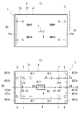
図1は、表示装置1の分解斜視図である。
図2の(A)は、表示装置1をタッチパネル21側から見た正面図であって、タッチパネル21の裏側に位置する液晶表示パネル22とショックアブソーバ6とソレノイド8の位置を破線で示した図である。
図2の(B)は、表示装置1においてタッチパネル21の裏側に位置する主要部品の位置を破線で示した図である。Hereinafter, embodiments of the present invention will be described by taking as an example a case of a display device 1 (touch panel device) mounted on a vehicle and operated by a user.
FIG. 1 is an exploded perspective view of the
FIG. 2A is a front view of the
(B) of FIG. 2 is a diagram showing the positions of the main components located on the back side of the
図1に示すように、表示装置1は、タッチパネル21と、液晶表示パネル22と、ホルダ3と、リアカバー4と、プリント基板5と、を有している。
タッチパネル21と、液晶表示パネル22と、ホルダ3で、発明にかかる表示部2を構成する。表示部2は、当該表示部2の裏面を覆うリアカバー4で、表示部2の厚み方向に変位可能に支持されている。As shown in FIG. 1 , the
The
タッチパネル21は、ユーザの手指による操作を検知可能な従来公知のタッチパネルである。平面視においてタッチパネル21は、長方形形状を成しており、液晶表示パネル22の前面を覆う大きさを有している(図2の(A)参照)。 The
液晶表示パネル22は、TFT液晶などの従来公知の液晶表示パネルである。液晶表示パネル22もまた、平面視において長方形形状を有している。液晶表示パネル22の前面は、情報の表示面22a(図1参照)であり、液晶表示パネル22の表示面22aはタッチパネル21で覆われている。 The liquid
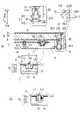
図3の(A)は、表示装置1の断面図であって、図2の(B)におけるA-A断面を模式的に示した図である。図3の(B)は、表示部2が変位した際のセンサ7におけるスペーサ72の変位を説明する図である。
図4の(A)は、表示装置1の断面図であって、図2の(B)におけるB-B断面を模式的に示した図である。図4の(B)は、表示部2が変位した際のセンサ7における係合部324と係止部421の配置を説明する図である。FIG. 3A is a cross-sectional view of the
FIG. 4A is a cross-sectional view of the
なお、以下の説明においては、表示装置1の構成部品の位置関係を、必要に応じて、図3の(A)における上下方向を基準として説明する。 In the following description, the positional relationship of the constituent parts of the
図3に示すように、ホルダ3は、液晶表示パネル22の裏面を支持する底壁部31と、底壁部31の外周縁を全周に亘って囲む周壁部32と、を有している。
周壁部32は、液晶表示パネル22の外周を囲む枠部321と、タッチパネル21の外周を囲む化粧枠322と、タッチパネル21外周縁が着座する支持部323と、を有している。
平面視において周壁部32は、矩形形状を有している。化粧枠322は、枠部321よりも大きい開口径で形成されている。As shown in FIG. 3, the
The
The
支持部323は、枠部321と化粧枠322との接続部である。支持部323は、枠部321の上端から外側に延びたのち、化粧枠322の下端に接続している。
周壁部32において支持部323は、化粧枠322の内周に沿って設けられている。化粧枠322の内側において支持部323は、略全周に亘って設けられている。
タッチパネル21の外周縁を支持部323に着座させると、タッチパネル21が化粧枠322の内側に配置される。The
A
When the outer peripheral edge of the
ホルダ3の枠部321は、リアカバー4の周壁部42の内側に挿入されている。リアカバー4は、底壁部41と、底壁部41の外周を全周に亘って囲む周壁部42と、を有している。平面視においてリアカバー4は、長方形形状を成している。
周壁部42は、ホルダ3側の化粧枠322と整合する外形で形成されている。表示装置1をタッチパネル21側から見ると、ホルダ3側の化粧枠322の裏側に、リアカバー4の周壁部42が隠れている。The
The
リアカバー4の周壁部42の上端42aは、ホルダ3とリアカバー4との重ね合わせ方向(図3の(A)における上下方向)で、化粧枠322の裏面322bに隙間Sを空けて対向している。
平面視においてリアカバー4では、底壁部41の四隅にショックアブソーバ6が設けられている(図2の(A)、図3の(A)参照)。
ショックアブソーバ6は、液晶表示パネル22の幅方向の中心線C1を挟んだ一方側(図中、左側)と、他方側(図中、右側)にそれぞれ、二つずつ設けられている。An
Two
一方側のショックアブソーバ6は、液晶表示パネル22の幅方向の一方の側縁22cと重なる位置に設けられている。これらショックアブソーバ6、6は、液晶表示パネル22の高さ方向(図2の(A)における上下方向)の中心線C2を間に挟んで対称となる位置関係で設けられている。
他方側のショックアブソーバ6は、液晶表示パネル22の幅方向の他方の側縁22dと重なる位置に設けられている。これらショックアブソーバ6、6は、中心線C2を間に挟んで対称となる位置関係で設けられている。
ここで、中心線C2は、液晶表示パネル22の中央で、前記した中心線C1に直交する直線である。The
The
Here, the center line C2 is a straight line at the center of the liquid
図3の(A)に示すように、ショックアブソーバ6は、リアカバー4の底壁部41に固定された弾性部材61と、この弾性部材61とホルダ3とを連結するボルト62と、を有している。
弾性部材61は、ゴムなどの振動吸収性に優れた材料で形成されている。弾性部材61は、円筒状の基部601と、基部601の外周に設けた嵌合溝602と、を有している。嵌合溝602は、基部601の外周に全周に亘って設けられている。As shown in FIG. 3A, the
The
リアカバー4の底壁部41では、ショックアブソーバ6が設置される領域に、開口部410が設けられている。ショックアブソーバ6の弾性部材61は、この開口部410の部分で、基部601の外周に設けた嵌合溝602に、底壁部41を内嵌させて設けられている。 The
ボルト62は、円筒状の基部601の内側を、リアカバー4の外側からホルダ3側に貫通している。ボルト62の先端側は、ホルダ3の底壁部31に設けた脚部312に螺入している。
図2の(A)に示すように、表示装置1においてショックアブソーバ6は、ふたつの中心線C1、C2により区画される4つの領域1~領域4の各々に設けられている。これらショックアブソーバ6は、ソレノイド8(中心線C1と中心線C2との交点P)を基準とした右斜め上の領域と、右斜め下の領域と、左斜め上の領域と、左斜め下の領域の各々に一つずつ設けられている。
ホルダ3は、合計4つのショックアブソーバ6を介して、リアカバー4で支持されている。そのため、ホルダ3を含む表示部2の振動が、ショックアブソーバ6の部分で吸収されるようになっている。The
As shown in FIG. 2A, in the
The
図2の(B)に示すように、ショックアブソーバ6から見て、中心線C1側には、センサ7が設けられている。
図3の(A)に示すように、センサ7は、アンテナ71と、スペーサ72と、を有している。
アンテナ71は、プリント基板5におけるホルダ3側の表面5aに設けられている。プリント基板5には、ホルダ3側の支持筒311を挿通させる挿通孔50が設けられている。
ホルダ3側から見てアンテナ71は、挿通孔50を囲むリング状を成している。As shown in FIG. 2B, the
As shown in FIG. 3A, the
The
The
支持筒311は、ホルダ3の底壁部31と一体に形成されており、リアカバー4の底壁部41側の下方に向けて突出している。
支持筒311は、プリント基板5に設けた挿通孔50を、リアカバー4の底壁部41側に貫通している。
支持筒311の下端には、スペーサ72がボルト73で固定されている。
スペーサ72は、支持筒311の下端に固定される円板部721と、円板部721の外周縁を全周に亘って囲む周壁部722と、フランジ部723と、を有している。The
The
A
The
フランジ部723は、周壁部722のプリント基板5側(図中、上側)の端部を全周に亘って囲んでいる。プリント基板5側から見てフランジ部723は、リング状に形成されている。フランジ部723は、前記したアンテナ71の外径rと略整合する外径で形成されている。
センサ7では、フランジ部723と、プリント基板5のアンテナ71は、プリント基板5の厚み方向に間隔をあけて配置される。
フランジ部723がプリント基板5の裏面5bに接触した位置に配置されると、フランジ部723とアンテナ71は、プリント基板5の厚み方向に間隔L1だけ離間して配置される。The
In the
When the
表示装置1では、ユーザによるタッチパネル21の操作により、表示部2がリアカバー4の底壁部41側の下方に変位すると、支持筒311に固定されたスペーサ72もまた、表示部2の変位に連動して底壁部41側に変位する。 In the
これにより、プリント基板5の厚み方向におけるアンテナ71とフランジ部723との間隔が拡大して、センサ7で検出される静電容量が変化することで、後記する制御装置10において、表示部2の変位が検出されるようになっている。
なお、本実施形態では、フランジ部723とアンテナ71が、プリント基板5の厚み方向に間隔L2離間した時点で、制御装置10により、表示部2の変位が検出されるようになっている。As a result, the distance between the
In this embodiment, when the
表示装置1では、タッチパネル21が操作された際に、ボルト73で固定されたスペーサ72が、リアカバー4の底壁部41に干渉して変位できなくなることを防止するために、以下のようにしている。
スペーサ72のフランジ部723をプリント基板5の裏面5bに接触させた状態で、スペーサ72を固定するボルト73と、リアカバー4の底壁部41との間に、表示部2の変位可能量よりも大きい隙間S1が確保されるようにしている。In the
With the
図2の(B)に示すように、本実施形態では、センサ7は、プリント基板5の四隅に位置している。表示装置1においてセンサ7は、ふたつの中心線C1、C2により区画される4つの領域1~領域4の各々に設けられている。
そのため、表示装置1では、これら4つの領域1~領域4に対応するタッチパネル21のどの領域が操作されても、タッチパネル21の操作に起因する表示部2の変位を検出できるようになっている。As shown in FIG. 2B, the
Therefore, the
センサ7から見て中心線C1側には、支持筒411が設けられている。
支持筒411は、リアカバー4の底壁部41と一体に形成されている。支持筒411は、プリント基板5をリアカバー4で支持するために設けられている。
リアカバー4では、合計4つの支持筒411が設けられており、支持筒411の各々は、ふたつの中心線C1、C2により区画される4つの領域の各々に設けられている。A
The
A total of four
図3の(A)に示すように、支持筒411は、リアカバー4の底壁部41から、プリント基板5側の上方に突出している。支持筒411の各々は、それぞれ同じ高さh1で形成されている。
支持筒411は、プリント基板5の裏面5bに当接しており、支持筒411には、プリント基板5がビスで固定されている。As shown in FIG. 3A, the
The
図2の(B)に示すように、プリント基板5の中央部には、ソレノイド8との干渉を避けるための挿通孔50が設けられている。
さらに、プリント基板5には、位置決め孔51と切欠部52とが設けられており、挿通孔50と、位置決め孔51と、切欠部52は、中心線C2上で並んでいる。As shown in FIG. 2B, an
Further, the printed
切欠部52には、ホルダ3の底壁部31と一体に形成されたリブ314が、挿入されている。図2の(B)に示すように、切欠部52とリブ314は、表示装置1の幅方向の中心線C1を間に挟んで対称となる位置関係で設けられている。
リブ314、314は、表示装置1の幅方向(図中、左右方向)でのプリント基板5と表示部2との相対移動を規制している。A
The
図4の(A)に示すように、位置決め孔51には、リアカバー4の底壁部41と一体に形成された位置決めピン412が、挿入されている。
プリント基板5の挿通孔50には、ホルダ3の底壁部31と一体に形成された囲繞壁313が挿入されている。As shown in FIG. 4A , a
A surrounding
ホルダ3の底壁部31では、囲繞壁313で囲まれた裏面31bに、ソレノイド8の当接部83が当接している。この囲繞壁313で囲まれた領域が、発明における中央領域に相当する。 In the
図4の(A)示すように、リアカバー4では、底壁部41の中央部に、プリント基板5から離れる方向に窪んだ凹部413が設けられている。凹部413には、ソレノイド8が設置されている。
ソレノイド8は、コイル81への通電/非通電の切替により進退移動するシャフト82を有している。As shown in FIG. 4A, the
The
シャフト82のプリント基板5側の端部には、矩形形状の当接部83が設けられている。
ソレノイド8では、コイル81への非通電時に、当接部83が、ホルダ3の裏面31bに全面に亘って当接した位置に保持される。さらに、シャフト82には、スプリングSpが外挿されており、当接部83は、スプリングSpの付勢力によっても、ホルダ3の裏面31bに当接している。
そのため、コイル81への非通電時には、ソレノイド8による保持力とスプリングSpの付勢力が、当接部83を介してホルダ3に作用している。A
In the
Therefore, when the
図4の(B)に示すように、ホルダ3の周壁部32では、底壁部31の延長上に、係合部324が設けられている。
係合部324は、側方に延出すると共に、前記した支持部323に対して平行に設けられている。係合部324と支持部323は、表示部2の厚み方向(図中、上下方向)に間隔を開けて設けられている。
係合部324の外側に位置する周壁部42では、枠部321に対向する領域の内周に、支持部323と係合部324との間に挿入される係止部421が設けられている。As shown in FIG. 4B, the
The engaging
In the
図2の(B)に示すように、表示装置1において係止部421(係止部421a、421b)は、幅方向(図中、左右方向)の両側に設けられている。
リアカバー4では、前記した中心線C2に交差する位置に設けた幅広の係止部421aと、中心線C2を挟んだ一方側と他方側に、それぞれ二つずつ設けられた係止部421bと、が設けられている。As shown in FIG. 2B, in the
In the
そのため、ホルダ3の周壁部32では、リアカバー4側の係止部421に対応する位置に、係合部324が設けられており、タッチパネル21側から見て、リアカバー4側の係止部421と、ホルダ3側の係合部324とが、重なる位置関係で設けられている。 Therefore, on the
前記したように、ソレノイド8のシャフト82は、コイル81への通電/非通電の切替により、表示部2の厚み方向(図4の(A)における上下方向)に進退移動する。
コイル81への非通電時には、ソレノイド8による保持力とスプリングSpの付勢力が、当接部83を介してホルダ3に作用しており、ホルダ3は、タッチパネル21側の上方に向けて付勢されている。As described above, the
When the
そのため、ホルダ3は、底壁部31の外周に設けた係合部324を、リアカバー4側の係止部421に圧接させた位置(規制位置)で位置決めされる(図4の(A)参照)。
この状態では、ホルダ3側の支持部323と、リアカバー4側の係止部421との間に、上下方向の隙間Δt1が形成されるものの、ホルダ3側の係合部324がリアカバー4側の係止部421に圧接した状態が、ソレノイド8の保持力により確保されている。
そのため、ホルダ3で支持された表示部2は、リアカバー4から離れる方向(図中、上方向)への変位だけでなく、リアカバー4に近づく方向(図中、下方向)への変位も規制されている。
すなわち、ホルダ3で支持された表示部2と、リアカバー4との相対移動が規制される。Therefore, the
In this state, a vertical gap Δt1 is formed between the
Therefore, the
That is, relative movement between the
また、コイル81への通電時には、シャフト82がリアカバー4の底壁部41側の下方に引き込まれる。そうすると、ホルダ3は、係合部324を係止部421に圧接させた位置(図4の(A)参照)から、圧接させていない位置(図4の(B)参照)まで変位する。
この状態では、ホルダ3側の支持部323と、リアカバー4側の係止部421との間の隙間がΔt2まで狭められる一方で、ホルダ3側の係合部324とリアカバー4側の係止部421との間にΔt3の隙間が形成される。
そのため、ホルダ3で支持された表示部2は、リアカバー4との相対移動が許容されており、表示部2はリアカバー4から離れる方向(図中、上方向)への変位と、リアカバー4に近づく方向(図中、下方向)への変位が許容される。Further, when the
In this state, the gap between the
Therefore, the
表示装置1では、制御装置10は、タッチパネル21のタッチ操作のためのユーザ動作が検知される前の段階では、表示部2をリアカバー4との相対変位が規制された規制位置に保持している。
そして、タッチパネル21のタッチ操作のためのユーザ動作が検知されると、制御装置10は、ソレノイド8を駆動して、表示部2を、規制位置から、リアカバー4との相対変位が許容された許容位置まで変位させる。
すなわち、表示部2は、タッチパネル21の操作のためのユーザ動作が検知された場合にのみ、許容位置に配置される。In the
Then, when a user operation for touch operation on the
In other words, the
図5は、表示装置1のブロック図である。
液晶表示パネル22の表示面22a(図1参照)には、表示装置1の制御装置10により、例えば車載機器の操作用のアイコンが表示される。FIG. 5 is a block diagram of the
On the
表示装置1では、ユーザの手指が、液晶表示パネル22上のアイコンに触れると、タッチパネル21におけるユーザの手指がタッチした座標を示す座標データが、タッチパネル21から制御装置10(図3参照)に入力される。 In the
制御装置10は、入力された座標データに基づいて、ユーザの手指がタッチしたタッチパネル21上の座標を特定し、制御装置10は、特定した座標に表示されたアイコンに割り当てられた処理を実施する。
例えば、タッチされたアイコンが、液晶表示パネル22の表示輝度を上昇させるためのアイコンである場合、制御装置10は、液晶表示パネル22の表示輝度を上昇させる。Based on the input coordinate data, the
For example, when the touched icon is an icon for increasing the display brightness of the liquid
さらに、表示装置1では、車室内の表示装置1周りの撮像画像が、カメラCMから制御装置10に入力される。制御装置10は、入力された撮像画像から、タッチパネル21の操作のためのユーザ動作を検知する。
なお、表示装置1とは別の外部の画像処理装置により、タッチパネル21の操作のためのユーザ動作を検知して、画像処理装置から、タッチパネル21の操作のためのユーザ動作が検知されたことが通知されるようにしても良い。Furthermore, in the
Note that an external image processing device separate from the
タッチパネル21の操作のためのユーザ動作が検知されると、制御装置10がソレノイド8を駆動して、表示部2を規制位置(図4の(A)参照)から許容位置(図4の(B)参照)まで変位させる。
これにより、表示部2がリアカバー4に対して相対変位できる状態となり、タッチパネル21がユーザにより操作されると、表示部2は、操作力に応じて、リアカバー4の底壁部41側に変位することになる。When a user action for operating the
As a result, the
表示装置1では、タッチパネル21の操作により表示部2が変位すると、表示部2の変位を検出するセンサ7の出力値が変化する。制御装置10は、センサ7の出力値の変化により、表示部2の変位を確認すると、ソレノイド8を駆動して、表示部2を振動させる。
これにより、タッチパネル21を操作したユーザに、タッチパネルを介した入力操作が、表示装置1側で検知されたことを、表示部2の振動により伝えることができる。In the
Accordingly, the vibration of the
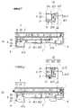
図6は、表示装置1の制御装置10における処理を説明するフローチャートである。
図7は、表示装置1のタッチパネル21の操作時の動作を説明する図である。FIG. 6 is a flowchart for explaining processing in the
7A and 7B are diagrams for explaining the operation when the
始めに、制御装置10は、タッチパネル21の操作のためのユーザ動作、例えば、手指Fをタッチパネル21に近づける動作の有無を確認する(ステップS101)。
前記したように、制御装置10には、カメラCMから撮像画像が入力される。
例えば、カメラCMが、タッチパネル21周りの領域を向いて配置されていると、カメラCMから入力される撮像画像に対して、従来公知の画像処理を実施することで、ユーザが、タッチパネル21の操作のためのユーザ動作を実施したか否かを確認できる。First, the
As described above, the captured image is input to the
For example, when the camera CM is arranged facing the area around the
ユーザがタッチパネル21の操作のためのユーザ動作を実施した場合(ステップS101、Yes)、制御装置10は、ソレノイド8を駆動して、表示部2を、規制位置(図4の(A)参照)から許容位置(図4の(B)参照)まで変位させる。 When the user performs a user action for operating the touch panel 21 (step S101, Yes), the
規制位置に配置された表示部2では、ホルダ3側の支持部323と、リアカバー4側の係止部421との間に、上下方向の隙間Δt1が形成されるものの、ホルダ3側の係合部324がリアカバー4側の係止部421に圧接した状態が、ソレノイド8の保持力により確保されている。そのため、表示部2は、リアカバー4との相対変位が規制されている(図7の(B)参照)。 In the
表示部2が許容位置に配置されると、ホルダ3側の支持部323と、リアカバー4側の係止部421との間の隙間がΔt2まで狭められる一方で、ホルダ3側の係合部324とリアカバー4側の係止部421との間にΔt3の隙間が形成される(図7の(B)参照)。
そのため、ホルダ3で支持された表示部2は、リアカバー4との相対移動が許容されており、表示部2は、リアカバー4との相対変位が許容される。When the
Therefore, the
この状態において、表示部2が、ユーザの手指Fにより押されると、表示部2が、リアカバー4側に変位することになる(図7の(C)参照)。
そのため、制御装置10は、表示部2を許容位置に配置(ステップS102)のち、表示部2が変位したか否かを確認する(ステップS103)。In this state, when the
Therefore, the
表示装置1では、表示部2のリアカバー4側への変位により、センサ7のスペーサ72(フランジ部723)がプリント基板5から離れる方向に変位する(図3参照)。
これにより、センサ7のアンテナ71と、フランジ部723との離間距離が、初期状態のL1からL2まで増えた時点で、制御装置10が、表示部2が変位したと判定する(S103)。
この時点では、ホルダ3側の支持部323と、リアカバー4側の周壁部42との間の隙間がΔt2’まで狭められている。In the
As a result, when the separation distance between the
At this point, the gap between the
表示部2が変位したことが確認されると(ステップS103、Yes)、制御装置10は、ソレノイド8を駆動して、表示部2を振動させる(ステップS104)。同時に、タッチされたアイコンが、液晶表示パネル22の表示輝度を上昇させるためのアイコンである場合、制御装置10は液晶表示パネル22の表示輝度を上昇させる。
これにより、タッチパネル21の操作が、表示装置1に入力されたことが、ユーザに振動として伝達される。When it is confirmed that the
Accordingly, the fact that the operation of the
そして、制御装置10は、ソレノイド8を駆動して、表示部2を、許容位置(図4の(B)参照)から規制位置(図4の(A)参照)まで変位させる(ステップS106)。
これにより、表示部2は、リアカバー4との相対変位が規制された状態となる。
よって、新たにタッチパネル21の操作のためのユーザ動作が検出されるまでの間、表示部2は、リアカバー4との相対変位が規制された状態で保持される。Then, the
As a result, the
Therefore, the
なお、表示部2を許容位置に配置(ステップS102)のち、所定時間が経過するまでの間に、表示部2の変位が確認されない場合にも(ステップS103、Nо)、ステップS106の処理が実施される。
これにより、タッチパネル21の操作のためのユーザ動作が検出されたにもかかわらず、タッチパネル21が操作されなかった場合に、表示部2が、許容位置に配置したままで保持されないようになっている。After the
As a result, when the
このように、タッチパネル21の操作のためのユーザ動作が検知されるまでの間は、表示部2が規制位置に配置されて、表示部2の変位が規制される。そして、タッチパネル21の操作のための動作が検知された後の所定期間の間だけ、表示部2が許容位置に配置されて、表示部の変位が許容される。
よって、タッチパネル21の操作に起因する表示部2の変位の有無の検出を適切に行って、必要に応じて表示部2を振動させることができる。In this way, the
Therefore, the presence or absence of displacement of the
これにより、表示装置1内の振動の影響を受けやすい部品であるセンサ7に、振動の影響が及び難くすることができる。 As a result, it is possible to make the
以上の通り、本実施形態にかかる表示装置1は、以下の構成を有している。
(1)表示装置1(タッチパネル装置)は、
ユーザによりタッチ操作されるタッチパネル21(操作面)を有する表示部2と、
タッチパネル21のタッチ操作による表示部2の変位を検出するセンサ7と、
表示部2を振動させるソレノイド8(アクチュエータ)と、
ソレノイド8を制御する制御装置10と、を有する。
表示装置1は、表示部2の変位が検出されると、制御装置10が、ソレノイド8により表示部2を振動させることで、タッチパネル21を操作したユーザに、タッチパネル21の操作が検知されたことを伝えるように構成されたフォースフィードバック型の表示装置である。
表示部2は、ソレノイド8により、変位が規制される規制位置(図4の(A))と、変位が許容される許容位置(図4の(B))との間を変位可能である。
制御装置10は、表示部2を規制位置で保持すると共に、タッチパネル21のタッチ操作のためのユーザ動作が検知されると、表示部2を許容位置に配置して、表示部2を振動可能な状態にする。As described above, the
(1) The display device 1 (touch panel device) is
a
a
a solenoid 8 (actuator) that vibrates the
and a
In the
The
The
このように構成すると、タッチパネル21のタッチ操作のためのユーザ動作が検知されるまでの間は、表示部2の振動が規制される。これにより、表示装置1内の振動の影響を受けやすい部品であるセンサ7に、表示装置1を搭載した車両などに走行に起因する振動の影響が及び難くなる。 With this configuration, the vibration of the
本実施形態にかかる表示装置1は、以下の構成を有している。
(2)タッチパネル21側(操作面側)から見た正面視において、ソレノイド8は表示部2の厚み方向における裏側に配置されている。
ソレノイド8は、表示部2の中央領域の裏側を支持すると共に、表示部2を当該表示部2の厚み方向に振動させる。The
(2) When viewed from the
The
このように構成すると、表示部2の変位を1つのソレノイド8で行うことができる。表示部2の駆動に複数のアクチュエータを必要とする場合には、部品点数の増加により表示装置1の作製コストが上昇する。
表示部2の変位を、表示部2の中央領域の裏側を支持するひとつのソレノイド8で行うことで、表示装置1の作製コストの上昇を抑制できる。With this configuration, the
By displacing the
本実施形態にかかる表示装置1は、以下の構成を有している。
(3)規制位置に配置された表示部2は、ソレノイド8の保持力で、リアカバー4(固定側部材)側の係止部421(係止部)に押し付けられた状態で保持されている。The
(3) The
このように構成すると、表示部2を振動させるソレノイド8を、表示部2の変位規制に流用できるので、表示部2を振動させるためのソレノイドと、表示部2の変位を規制するためのアクチュエータとを別々に用意する必要が無い。これにより、表示装置1の大型化を防ぎつつ、作製コストの増加を抑制できる。 With this configuration, the
本実施形態にかかる表示装置1は、以下の構成を有している。
(4)ソレノイド8は、表示部2を収容するリアカバー4の底壁部41に支持されている。
係止部421は、底壁部41の外周縁を囲む周壁部42の内周に設けられている。
許容位置に配置された表示部2は、ソレノイド8を介してリアカバー4で支持されている。
規制位置に配置された表示部は、ソレノイド8と係止部421とを介して、リアカバー4で支持されている。The
(4) The
The locking
The
The display portion arranged at the restricted position is supported by the
このように構成すると、許容位置に配置された表示部2は、ソレノイド8のみを介してリアカバー4で支持されているので、ユーザによるタッチパネルの操作に連動して、表示部2を速やかに変位させることができる。
また、規制位置に配置された表示部2は、ソレノイド8と係止部421とを介して、リアカバー4で支持されて、リアカバー4との相対変位が規制されている。そのため、表示装置1を搭載した車両の走行時に、走行に起因する振動が連続的に表示部2に作用することを好適に防止できる。With this configuration, the
Further, the
本実施形態にかかる表示装置1は、以下の構成を有している。
(5)タッチパネル21側から見た正面視において、表示部2は、中央領域を間に挟んだ一方側と他方側の側縁部に、係合部324を有している。
規制位置に配置された表示部2は、ソレノイド8の保持力で、リアカバー4(固定側部材)の係止部421に、係合部324を押し付けられた状態で保持される。The
(5) In a front view from the
The
このように構成すると、ソレノイド8により、表示部2を振動させる際の変位方向と同じ方向(表示部の厚み方向)に、表示部2を変位させることで、規制位置と許容位置との間での変位を行える。 With this configuration, the
本実施形態にかかる表示装置1は、以下の構成を有している。
(6)ユーザを撮像するカメラCMを有している。
制御装置10は、カメラCMの撮像画像から、タッチパネル21のタッチ操作のためのユーザ動作の有無を判定する。The
(6) It has a camera CM that captures an image of the user.
The
このように構成すると、タッチパネル21のタッチ操作のためのユーザ動作の有無を適切に判定できる。
また、例えば、乗員をモニタするカメラの撮像画像を用いて、タッチパネル21の操作のためのユーザ動作の有無を判定することで、ユーザ動作の判定用のカメラを別途用意する必要が無い。
これにより、表示装置1の作製コストの上昇を好適に防止できる。With this configuration, it is possible to appropriately determine whether or not there is a user action for a touch operation on the
Further, for example, by determining whether or not there is a user motion for operating the
As a result, an increase in manufacturing cost of the
本実施形態にかかる表示装置1は、以下の構成を有している。
(7)センサ7は、リアカバー4(固定側部材)側のプリント基板5で支持されたアンテナ71(固定部)と、表示部2と一体に変位して、アンテナ71との距離が変化するスペーサ72(フランジ部723:可動部)と、を有している。
センサ7では、アンテナ71とフランジ部723との距離の変化により、タッチパネル21の操作による表示部2の変位を検出する。The
(7) The
The
例えば表示装置1が車両に搭載されている場合、車両の走行に起因する振動(外部振動)が表示装置1に作用する。ここで、表示部2の変位が規制されていないときには、外部振動に起因する外力が表示部に入力される。そうすると、表示装置1における振動の影響を受けやすい部品であるセンサ7にも外力が作用する。
ここで、センサ7は、相対移動する2つの部品(アンテナ71、スペーサ72)を有しているので、継続的に入力される振動で2つの部品が相対移動を継続すると、センサ7による検出に影響が生じる場合がある。
上記のように構成すると、表示部2の変位を検出する必要が無いときには、センサ7を構成する2つの部品の相対移動を規制できる。これにより、継続的に入力される振動で2つの部品が相対移動することを防止できるので、センサ7による検出が、振動の影響を受け難くなる。For example, when the
Here, since the
With the above configuration, when there is no need to detect the displacement of the
本実施形態にかかる表示装置1は、以下の構成を有している。
(8)表示部2をタッチパネル21側から見た正面視において、長方形形状を成す表示部2は、四隅に設けたショックアブソーバ6を介して、固定側部材であるリアカバー4の底壁部41に支持されている。
表示装置1においてショックアブソーバ6は、ふたつの中心線C1、C2により区画される4つの領域1~領域4の各々に設けられている。
ショックアブソーバ6で支持された表示部2は、表示部2の厚み方向に変位可能であり、表示部2の厚み方向の変位による振動が、ショックアブソーバ6で減衰される。The
(8) When the
In the
The
このように構成すると、表示部2の振動を、ショックアブソーバ6の部分で吸収される。これにより、表示装置1における振動の影響を受けやすい部品であるセンサ7に作用する振動を抑制できる。 With this configuration, the vibration of the
[変形例]
前記した実施形態では、タッチパネル21の操作のためのユーザ動作の有無を、カメラCMによる撮像画像により判定する場合を例示した。
タッチパネル21の操作のためのユーザ動作の有無を判定する方法は、この方法にのみ限定されない。
例えば、タッチパネルが静電容量の変化を検出するタイプのタッチパネルである場合には、タッチパネル21により、当該タッチパネル21の操作のためのユーザ動作の有無を判定するようにしても良い。[Modification]
In the above-described embodiment, the case where the presence/absence of a user's action for operating the
The method of determining whether or not there is a user action for operating the
For example, if the touch panel is of a type that detects changes in capacitance, the
例えば、タッチパネル21の検出感度を切り替えることができる場合には、以下のようにしても良い。
制御装置10が、タッチパネル21の検出感度を、当該タッチパネル21へのユーザの手指の接近を検出可能な第1検出感度と、タッチパネル21のタッチ操作を検出可能であって、第1検出感度よりも低い第2検出感度との間で切り替える。
制御装置10は、
表示部2を規制位置に配置しているときに、タッチパネル21の検出感度を第1検出感度に設定し、タッチパネル21へのユーザの手指の接近が検出されると、タッチパネル21の検出感度を第1検出感度から第2検出感度に変更する。
これにより、制御装置10が、タッチパネル21へのユーザの手指の接近が検出された時点で、表示部2を規制位置から許容位置まで変位させることで、その後のタッチ操作を適切に検出できる。For example, if the detection sensitivity of the
The
The
The detection sensitivity of the
Thereby, when the approach of the user's finger to the
このように、変形例にかかる表示装置1は、以下の構成を有する。
(9)タッチパネル21の検出感度は、タッチパネル21へのユーザの手指の接近を検出可能な第1検出感度と、タッチパネル21のタッチ操作を検出可能であって、第1検出感度よりも低い第2検出感度との間で切り替え可能である。
制御装置10は、表示部2を規制位置に配置しているときに、タッチパネル21の検出感度を第1検出感度に設定する。タッチパネル21へのユーザの手指の接近が検出されると、タッチパネル21の検出感度を第1検出感度から第2検出感度に変更する。さらに、表示部2を規制位置から許容位置まで変位させる。Thus, the
(9) The detection sensitivity of the
The
このように構成することによっても、タッチパネル21の操作のためのユーザ動作の有無を適切に判定できる。
そして、タッチパネル21のタッチ操作のためのユーザ動作が検知されるまでの間は、表示部2の振動が規制される。これにより、表示装置1内の振動の影響を受けやすい部品であるセンサ7に、表示装置1を搭載した車両などに走行に起因する振動の影響が及び難くなる。By configuring in this way, it is also possible to appropriately determine whether or not there is a user action for operating the
Vibration of the
[変形例2]
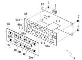
図8は、他の変形例にかかる表示装置1Aの分解斜視図である。
図9は、他の変形例にかかる表示装置1Aの化粧パネル90の正面図である。
前記した実施形態では、ユーザによりタッチ操作される操作面が、タッチパネル21である場合を例示した。
本件発明は、例えばユーザのタッチ操作を、フイルム電極91を用いて検出する構成の表示装置1Aにも適用可能である。[Modification 2]
FIG. 8 is an exploded perspective view of a
FIG. 9 is a front view of a
In the above-described embodiment, the
The present invention can also be applied to a
図8および図9に示すように、表示装置1Aは、表面(操作面)90aに複数のアイコンMKが印刷された化粧パネル90を有している。化粧パネル90は、例えば、車室内のインストルメントパネルにおいて、ユーザにより操作可能な位置に設置される。
化粧パネル90は、図示しないリアカバーに、図示しないショックアブソーバを介して支持されており、この状態において化粧パネル90は、当該化粧パネル90の厚み方向に変位可能に支持されている(前述の実施形態と同一)。As shown in FIGS. 8 and 9, the
The
化粧パネル90は、非導電性の材料から構成されており、化粧パネル90の裏側には、タッチ操作を検出するためのフイルム電極91と、プリント基板92が位置している。
なお、表示装置1Aにおける他の構成要素は、前記した表示装置1と同じであるので、ここでは説明を省略する。The
The other components of the
化粧パネル90の中央部には、液晶表示パネル22が嵌め込まれる開口部901が設けられている。
化粧パネル90の表面には、任意の機能が割り当てられた操作領域が複数設けられている(操作領域R1~R12:図9参照)。化粧パネル90では、これら操作領域R1~R12が所定の面積を持って設定されていると共に、操作領域R1~R12の厚みが、他の領域よりも薄くなるように設定されている。An
A plurality of operation areas to which arbitrary functions are assigned are provided on the surface of the decorative panel 90 (operation areas R1 to R12: see FIG. 9). In the
そのため、操作領域R1~R12は、フイルム電極91との対向方向(化粧パネル90の厚み方向)に変位可能であり、ユーザにより、操作領域R1~R12の何れかがタッチ操作されると、タッチされた操作領域がフイルム電極91に近づく方向に変位する。 Therefore, the operation regions R1 to R12 can be displaced in the direction facing the film electrode 91 (thickness direction of the decorative panel 90), and when the user touches any of the operation regions R1 to R12, the touch operation is performed. The operation area is displaced in a direction approaching the
各操作領域R1~R12のプリント基板92側には、フイルム電極91が設けられている。
フイルム電極91は、可撓性のあるFPC(Flexible Printed Circuits)で構成されており、ベースフィルム910と、このベースフィルム910から、プリント基板92まで延びる端子部911と、を有している。A
The
ベースフィルム910では、化粧パネル90側の表面に透明又は半透明の電極91aが複数設けられている。これら複数の電極91aの各々は、化粧パネル90の操作領域R1~R12に、1対1の関係で設けられている。複数の電極91aと、複数の操作領域R1~R12は、化粧パネル90の厚み方向で間隔をあけて対向している。 In the
表示装置1Aでは、何れかの操作領域がタッチ操作されると、操作された操作領域がフイルム電極91側に変位して、操作領域と電極91aとの位置関係が変化する。操作領域と電極91aとの位置関係の変化は、電極91aの静電容量の変化となって検出可能である。
表示装置1Aの制御装置10は、各電極91aの静電容量の変化の有無に基づいて、各電極91aが対応する操作領域におけるタッチ操作の有無を確認する。In the
The
図8および図9に示すように、平面視において表示装置1Aでは、プリント基板92の四隅に、センサ7が設けられている。センサ7は、前記した表示装置1のセンサ7と同じ構成と、役割を有するセンサである。
センサ7は、化粧パネル90の操作領域のタッチ操作に伴う化粧パネル90の変位を検出するために設けられている。As shown in FIGS. 8 and 9,
The
さらに、化粧パネル90では、操作領域R1と操作領域R7との間の領域の裏面に、ソレノイド8が当接している。ソレノイド8もまた、前記した表示装置1のセンサ7と同じ構成と、役割を有するセンサであり、表示装置1が備える制御装置10により駆動される。 Furthermore, in the
ソレノイド8は、化粧パネル90を、当該化粧パネル90の振動を許容する許容位置と、振動を規制する規制位置との間で変位させると共に、操作領域のタッチ操作が確認されると、化粧パネル90を振動させる。 The
かかる構成の表示装置1Aにおいても、タッチパネル21の操作のためのユーザ動作が検知されるまでの間、化粧パネル90の振動が規制される。これにより、表示装置1A内の振動の影響を受けやすい部品であるセンサ7に、振動の影響が及び難くなる。 Also in the
以上の通り、変形例にかかる表示装置1Aは、以下の構成を有している。
(10)表示装置1は、
ユーザによりタッチ操作されると共に、操作面に複数の操作領域R1~R12が設けられた化粧パネル90と、
操作領域R1~R12の各々に1対1で対向配置された電極91aを複数有するフイルム電極91(電極シート)と、
ユーザのタッチ操作による化粧パネル90の変位を検出するセンサ7と、
化粧パネル90を振動させるソレノイド8(アクチュエータ)と、
ソレノイド8を制御する制御装置10と、を有する。
表示装置1は、化粧パネル90の変位が検出されると、制御装置10が、ソレノイド8により化粧パネル902を振動させることで、化粧パネル90の操作領域を操作したユーザに、操作領域の操作が検知されたことを伝えるように構成されたフォースフィードバック型の表示装置である。
化粧パネル90は、ソレノイド8により、変位が規制される規制位置と、変位が許容される許容位置との間を変位可能である。
制御装置10は、化粧パネル90を規制位置で保持すると共に、化粧パネル90の操作のためのユーザ動作が検知されると、化粧パネル90を、規制位置から前記許容位置まで変位させる。As described above, the
(10) The
A
a film electrode 91 (electrode sheet) having a plurality of
a
A solenoid 8 (actuator) that vibrates the
and a
In the
The
The
このように構成することによっても、表示装置1A内の振動の影響を受けやすい部品であるセンサ7などに、振動の影響が及ぶことを好適に防止できる。 By configuring in this way, it is also possible to suitably prevent the influence of the vibration on the
以上、本願発明の実施形態および変形例を説明したが、本願発明は、これらのものに限定されるものではなく、発明の技術的な思想の範囲内で適宜変更可能である。 Although the embodiments and modifications of the present invention have been described above, the present invention is not limited to these, and can be appropriately modified within the scope of the technical idea of the invention.
1、1A タッチ操作装置
2 表示部
21 タッチパネル
22 液晶表示パネル
3 ホルダ
31 底壁部
311 支持筒
312 脚部
313 囲繞壁
314 リブ
32 周壁部
321 枠部
322 化粧枠
323 支持部
324 係合部
4 リアカバー
41 底壁部
42 周壁部
421(421a、421b) 係止部
5 プリント基板
50 挿通孔
51 位置決め孔
52 切欠部
6 ショックアブソーバ
61 弾性部材
62 ボルト
7 センサ
71 アンテナ
72 スペーサ
723 フランジ部
73 ボルト
8 ソレノイド
81 コイル
82 シャフト
83 当接部
10 制御装置
CM カメラ
L1、L2 間隔
C1、C2 中心線
P 交点
S、S1 隙間
Sp スプリング
Claims (8)
Translated fromJapanese前記タッチ操作による前記表示部の変位を検出するセンサと、
前記表示部を振動させるアクチュエータと、
前記アクチュエータを制御する制御装置と、を有し、
前記タッチ操作による前記表示部の変位が検出されると、前記制御装置が、前記アクチュエータにより前記表示部を振動させる表示装置において、
前記表示部は、前記アクチュエータにより、変位が規制される規制位置と、変位が許容される許容位置との間で変位可能であり、
前記制御装置は、前記表示部を前記規制位置で保持すると共に、前記タッチ操作のためのユーザ動作が検知されると、前記表示部を前記許容位置に配置することを特徴とする表示装置。a display unit having an operation surface that is touch-operated by a user;
a sensor that detects displacement of the display unit due to the touch operation;
an actuator that vibrates the display unit;
a control device that controls the actuator;
In the display device, the control device causes the actuator to vibrate the display unit when a displacement of the display unit due to the touch operation is detected,
the display unit is displaceable by the actuator between a regulated position where displacement is regulated and a permissible position where displacement is permitted;
The display device, wherein the control device holds the display section at the restricted position, and arranges the display section at the allowable position when a user action for the touch operation is detected.
前記制御装置は、前記カメラの撮像画像から、前記タッチ操作のためのユーザ動作を検知することを特徴とする請求項1に記載の表示装置。having a camera for imaging the user,
2. The display device according to claim 1, wherein the control device detects a user action for the touch operation from an image captured by the camera.
前記タッチパネルの検出感度は、前記タッチパネルへのユーザの手指の接近を検出可能な第1検出感度と、前記タッチパネルのタッチ操作を検出可能であって、前記第1検出感度よりも低い第2検出感度との間で切り替え可能であり、
前記制御装置は、
前記表示部を前記規制位置に配置しているときに、前記タッチパネルの検出感度を前記第1検出感度に設定し、
前記タッチ操作のためのユーザ動作が検知されると、前記タッチパネルの検出感度を前記第1検出感度から前記第2検出感度に変更すると共に、前記表示部を前記許容位置に配置することを特徴とする請求項1に記載の表示装置。The operation surface is a touch panel covering the surface of the display unit,
The detection sensitivity of the touch panel includes a first detection sensitivity that can detect an approach of a user's finger to the touch panel, and a second detection sensitivity that can detect a touch operation of the touch panel and is lower than the first detection sensitivity. is switchable between and
The control device is
setting the detection sensitivity of the touch panel to the first detection sensitivity when the display unit is arranged at the restricted position;
When the user action for the touch operation is detected, the detection sensitivity of the touch panel is changed from the first detection sensitivity to the second detection sensitivity, and the display unit is arranged at the allowable position. The display device according to claim 1.
前記操作領域の各々に一対一で対向配置された電極を複数有する電極シートを有していることを特徴とする請求項1または請求項2に記載の表示装置。The operation surface is a non-conductive panel provided with a plurality of operation areas,
3. A display device according to claim 1, further comprising an electrode sheet having a plurality of electrodes arranged to face each other in a one-to-one correspondence with each of said operation regions.
前記規制位置に配置された前記表示部は、前記アクチュエータの保持力で、固定側部材の係止部に、前記係合部を押し付けられた状態で保持されることを特徴とする請求項3に記載の表示装置。In a front view of the display portion viewed from the operation surface side, the display portion has engaging portions at side edges on one side and the other side with the central region of the display portion sandwiched therebetween. ,
4. The display unit arranged at the restricted position is held in a state in which the engaging portion is pressed against the engaging portion of the stationary member by a holding force of the actuator. Display device as described.
前記センサでは、前記固定部と前記可動部との距離の変化により、前記タッチ操作による前記表示部の変位を検出することを特徴とする請求項3から請求項7の何れか一項に記載の表示装置。The sensor has a fixed portion supported by the fixed side member and a movable portion that is displaced integrally with the display portion to change the distance from the fixed portion,
8. The sensor according to any one of claims 3 to 7, wherein the sensor detects the displacement of the display section caused by the touch operation based on a change in the distance between the fixed section and the movable section. display device.
Priority Applications (4)
| Application Number | Priority Date | Filing Date | Title |
|---|---|---|---|
| JP2019208461AJP7194666B2 (en) | 2019-11-19 | 2019-11-19 | Display device |
| EP20207296.3AEP3825821B1 (en) | 2019-11-19 | 2020-11-12 | Display device |
| CN202011293752.3ACN112905037A (en) | 2019-11-19 | 2020-11-18 | Display device |
| US16/952,073US11429208B2 (en) | 2019-11-19 | 2020-11-18 | Display device |
Applications Claiming Priority (1)
| Application Number | Priority Date | Filing Date | Title |
|---|---|---|---|
| JP2019208461AJP7194666B2 (en) | 2019-11-19 | 2019-11-19 | Display device |
Publications (2)
| Publication Number | Publication Date |
|---|---|
| JP2021081956A JP2021081956A (en) | 2021-05-27 |
| JP7194666B2true JP7194666B2 (en) | 2022-12-22 |
Family
ID=73401450
Family Applications (1)
| Application Number | Title | Priority Date | Filing Date |
|---|---|---|---|
| JP2019208461AActiveJP7194666B2 (en) | 2019-11-19 | 2019-11-19 | Display device |
Country Status (4)
| Country | Link |
|---|---|
| US (1) | US11429208B2 (en) |
| EP (1) | EP3825821B1 (en) |
| JP (1) | JP7194666B2 (en) |
| CN (1) | CN112905037A (en) |
Cited By (1)
| Publication number | Priority date | Publication date | Assignee | Title |
|---|---|---|---|---|
| US11583438B1 (en) | 2007-08-21 | 2023-02-21 | Zeltiq Aesthetics, Inc. | Monitoring the cooling of subcutaneous lipid-rich cells, such as the cooling of adipose tissue |
Families Citing this family (2)
| Publication number | Priority date | Publication date | Assignee | Title |
|---|---|---|---|---|
| WO2024116684A1 (en)* | 2022-11-28 | 2024-06-06 | パナソニックオートモーティブシステムズ株式会社 | Input device and panel |
| JP2024159082A (en)* | 2023-04-28 | 2024-11-08 | ミネベアミツミ株式会社 | Contact Input Device |
Citations (4)
| Publication number | Priority date | Publication date | Assignee | Title |
|---|---|---|---|---|
| JP2010152888A (en) | 2008-12-23 | 2010-07-08 | Research In Motion Ltd | Portable electronic device and method of control |
| JP2013513865A (en) | 2009-12-10 | 2013-04-22 | アップル インコーポレイテッド | Touchpad with force sensor and actuator feedback |
| JP2013171377A (en) | 2012-02-20 | 2013-09-02 | Tokai Rika Co Ltd | Input device |
| JP2019186174A (en) | 2018-04-17 | 2019-10-24 | 株式会社東海理化電機製作所 | Switch device |
Family Cites Families (12)
| Publication number | Priority date | Publication date | Assignee | Title |
|---|---|---|---|---|
| US20060181517A1 (en)* | 2005-02-11 | 2006-08-17 | Apple Computer, Inc. | Display actuator |
| US20080143559A1 (en)* | 2006-12-18 | 2008-06-19 | Dietz Paul H | Appliance Control Panel |
| JP5288643B2 (en)* | 2009-02-06 | 2013-09-11 | パナソニック株式会社 | Image display device |
| CN102053720B (en)* | 2009-11-09 | 2014-12-31 | 联想(北京)有限公司 | Track equipment and input method thereof |
| WO2012090405A1 (en)* | 2010-12-28 | 2012-07-05 | Necカシオモバイルコミュニケーションズ株式会社 | Input device, input control method, program and electronic apparatus |
| JP2013131020A (en)* | 2011-12-21 | 2013-07-04 | Sony Corp | Electronic equipment |
| JP5904174B2 (en) | 2013-08-22 | 2016-04-13 | Smk株式会社 | Touch panel support structure |
| US20190079583A1 (en)* | 2017-09-08 | 2019-03-14 | Immersion Corporation | Haptic Actuation Systems for a Touch Surface |
| US10248211B1 (en)* | 2017-09-28 | 2019-04-02 | Apple Inc. | Ground-shifted touch input sensor for capacitively driving an electrostatic plate |
| US11245396B2 (en)* | 2018-05-11 | 2022-02-08 | Microsoft Technology Licensing, Llc | Limiting inadvertent actuations of a touchpad |
| US10599221B2 (en)* | 2018-06-15 | 2020-03-24 | Immersion Corporation | Systems, devices, and methods for providing limited duration haptic effects |
| CN108845710B (en)* | 2018-07-27 | 2021-09-07 | 上海天马微电子有限公司 | Touch panel, driving method thereof and touch device |
- 2019
- 2019-11-19JPJP2019208461Apatent/JP7194666B2/enactiveActive
- 2020
- 2020-11-12EPEP20207296.3Apatent/EP3825821B1/enactiveActive
- 2020-11-18USUS16/952,073patent/US11429208B2/enactiveActive
- 2020-11-18CNCN202011293752.3Apatent/CN112905037A/enactivePending
Patent Citations (4)
| Publication number | Priority date | Publication date | Assignee | Title |
|---|---|---|---|---|
| JP2010152888A (en) | 2008-12-23 | 2010-07-08 | Research In Motion Ltd | Portable electronic device and method of control |
| JP2013513865A (en) | 2009-12-10 | 2013-04-22 | アップル インコーポレイテッド | Touchpad with force sensor and actuator feedback |
| JP2013171377A (en) | 2012-02-20 | 2013-09-02 | Tokai Rika Co Ltd | Input device |
| JP2019186174A (en) | 2018-04-17 | 2019-10-24 | 株式会社東海理化電機製作所 | Switch device |
Cited By (1)
| Publication number | Priority date | Publication date | Assignee | Title |
|---|---|---|---|---|
| US11583438B1 (en) | 2007-08-21 | 2023-02-21 | Zeltiq Aesthetics, Inc. | Monitoring the cooling of subcutaneous lipid-rich cells, such as the cooling of adipose tissue |
Also Published As
| Publication number | Publication date |
|---|---|
| US11429208B2 (en) | 2022-08-30 |
| EP3825821A1 (en) | 2021-05-26 |
| US20210149506A1 (en) | 2021-05-20 |
| JP2021081956A (en) | 2021-05-27 |
| CN112905037A (en) | 2021-06-04 |
| EP3825821B1 (en) | 2024-07-17 |
Similar Documents
| Publication | Publication Date | Title |
|---|---|---|
| JP7194666B2 (en) | Display device | |
| US11347315B2 (en) | Electronic device with force sensor and haptic feedback in direction perpendicular to a direction of press | |
| US8098236B2 (en) | Touch-sensitive screen with haptic acknowledgement | |
| US7796124B2 (en) | Input device and electronic apparatus | |
| JP5744390B2 (en) | Input device and method for detecting user input using the input device | |
| US20190107889A1 (en) | Input device | |
| US10963089B2 (en) | Tactile sensation providing apparatus and tactile sensation providing method | |
| US10921628B2 (en) | Input device | |
| EP2194444A2 (en) | Method for providing haptic feedback in a touch screen | |
| KR102367747B1 (en) | Organic light emitting display and driving method for the same | |
| KR20120063344A (en) | Haptic driving assembly and electronic device using the same | |
| JP2019508777A (en) | Control interface for cars | |
| EP3570143B1 (en) | Responsive force generator and vehicle-mounted display device including responsive force generator | |
| JP5611078B2 (en) | Electronics | |
| JP4163045B2 (en) | Coordinate input device | |
| JP7317494B2 (en) | ELECTRONIC DEVICE AND METHOD OF CONTROLLING ELECTRONIC DEVICE | |
| US10168779B2 (en) | Vehicle operating device | |
| US10976584B2 (en) | Input device | |
| WO2019013044A1 (en) | Input device | |
| US20220179254A1 (en) | Display apparatus | |
| JP2017151895A (en) | Input auxiliary device, information processing device, and operation method of touch input device | |
| JP6780270B2 (en) | Electronics |
Legal Events
| Date | Code | Title | Description |
|---|---|---|---|
| A621 | Written request for application examination | Free format text:JAPANESE INTERMEDIATE CODE: A621 Effective date:20220225 | |
| A977 | Report on retrieval | Free format text:JAPANESE INTERMEDIATE CODE: A971007 Effective date:20221130 | |
| TRDD | Decision of grant or rejection written | ||
| A01 | Written decision to grant a patent or to grant a registration (utility model) | Free format text:JAPANESE INTERMEDIATE CODE: A01 Effective date:20221206 | |
| A61 | First payment of annual fees (during grant procedure) | Free format text:JAPANESE INTERMEDIATE CODE: A61 Effective date:20221212 | |
| R150 | Certificate of patent or registration of utility model | Ref document number:7194666 Country of ref document:JP Free format text:JAPANESE INTERMEDIATE CODE: R150 |