JP7194462B2 - Flexible ductile part shape estimation device and endoscope system including the same - Google Patents
Flexible ductile part shape estimation device and endoscope system including the sameDownload PDFInfo
- Publication number
- JP7194462B2 JP7194462B2JP2021036538AJP2021036538AJP7194462B2JP 7194462 B2JP7194462 B2JP 7194462B2JP 2021036538 AJP2021036538 AJP 2021036538AJP 2021036538 AJP2021036538 AJP 2021036538AJP 7194462 B2JP7194462 B2JP 7194462B2
- Authority
- JP
- Japan
- Prior art keywords
- flexible
- shape
- torque transmission
- probe
- transmission wire
- Prior art date
- Legal status (The legal status is an assumption and is not a legal conclusion. Google has not performed a legal analysis and makes no representation as to the accuracy of the status listed.)
- Active
Links
Images


Classifications
- A—HUMAN NECESSITIES
- A61—MEDICAL OR VETERINARY SCIENCE; HYGIENE
- A61B—DIAGNOSIS; SURGERY; IDENTIFICATION
- A61B1/00—Instruments for performing medical examinations of the interior of cavities or tubes of the body by visual or photographical inspection, e.g. endoscopes; Illuminating arrangements therefor
- A61B1/00002—Operational features of endoscopes
- A61B1/00004—Operational features of endoscopes characterised by electronic signal processing
- A61B1/00006—Operational features of endoscopes characterised by electronic signal processing of control signals
- A—HUMAN NECESSITIES
- A61—MEDICAL OR VETERINARY SCIENCE; HYGIENE
- A61B—DIAGNOSIS; SURGERY; IDENTIFICATION
- A61B1/00—Instruments for performing medical examinations of the interior of cavities or tubes of the body by visual or photographical inspection, e.g. endoscopes; Illuminating arrangements therefor
- A61B1/005—Flexible endoscopes
- A61B1/0051—Flexible endoscopes with controlled bending of insertion part
- A61B1/0057—Constructional details of force transmission elements, e.g. control wires
- A—HUMAN NECESSITIES
- A61—MEDICAL OR VETERINARY SCIENCE; HYGIENE
- A61B—DIAGNOSIS; SURGERY; IDENTIFICATION
- A61B1/00—Instruments for performing medical examinations of the interior of cavities or tubes of the body by visual or photographical inspection, e.g. endoscopes; Illuminating arrangements therefor
- A61B1/00002—Operational features of endoscopes
- A61B1/00057—Operational features of endoscopes provided with means for testing or calibration
- A—HUMAN NECESSITIES
- A61—MEDICAL OR VETERINARY SCIENCE; HYGIENE
- A61B—DIAGNOSIS; SURGERY; IDENTIFICATION
- A61B1/00—Instruments for performing medical examinations of the interior of cavities or tubes of the body by visual or photographical inspection, e.g. endoscopes; Illuminating arrangements therefor
- A61B1/00002—Operational features of endoscopes
- A61B1/00043—Operational features of endoscopes provided with output arrangements
- A61B1/00045—Display arrangement
- A—HUMAN NECESSITIES
- A61—MEDICAL OR VETERINARY SCIENCE; HYGIENE
- A61B—DIAGNOSIS; SURGERY; IDENTIFICATION
- A61B1/00—Instruments for performing medical examinations of the interior of cavities or tubes of the body by visual or photographical inspection, e.g. endoscopes; Illuminating arrangements therefor
- A61B1/005—Flexible endoscopes
- A61B1/0051—Flexible endoscopes with controlled bending of insertion part
- A61B1/0055—Constructional details of insertion parts, e.g. vertebral elements
- A—HUMAN NECESSITIES
- A61—MEDICAL OR VETERINARY SCIENCE; HYGIENE
- A61B—DIAGNOSIS; SURGERY; IDENTIFICATION
- A61B1/00—Instruments for performing medical examinations of the interior of cavities or tubes of the body by visual or photographical inspection, e.g. endoscopes; Illuminating arrangements therefor
- A61B1/005—Flexible endoscopes
- A61B1/009—Flexible endoscopes with bending or curvature detection of the insertion part
- G—PHYSICS
- G01—MEASURING; TESTING
- G01B—MEASURING LENGTH, THICKNESS OR SIMILAR LINEAR DIMENSIONS; MEASURING ANGLES; MEASURING AREAS; MEASURING IRREGULARITIES OF SURFACES OR CONTOURS
- G01B21/00—Measuring arrangements or details thereof, where the measuring technique is not covered by the other groups of this subclass, unspecified or not relevant
- G01B21/32—Measuring arrangements or details thereof, where the measuring technique is not covered by the other groups of this subclass, unspecified or not relevant for measuring the deformation in a solid
- G—PHYSICS
- G06—COMPUTING OR CALCULATING; COUNTING
- G06T—IMAGE DATA PROCESSING OR GENERATION, IN GENERAL
- G06T7/00—Image analysis
- G06T7/0002—Inspection of images, e.g. flaw detection
- G06T7/0012—Biomedical image inspection
- A—HUMAN NECESSITIES
- A61—MEDICAL OR VETERINARY SCIENCE; HYGIENE
- A61B—DIAGNOSIS; SURGERY; IDENTIFICATION
- A61B34/00—Computer-aided surgery; Manipulators or robots specially adapted for use in surgery
- A61B34/20—Surgical navigation systems; Devices for tracking or guiding surgical instruments, e.g. for frameless stereotaxis
- A61B2034/2046—Tracking techniques
- A61B2034/2061—Tracking techniques using shape-sensors, e.g. fiber shape sensors with Bragg gratings
- A—HUMAN NECESSITIES
- A61—MEDICAL OR VETERINARY SCIENCE; HYGIENE
- A61B—DIAGNOSIS; SURGERY; IDENTIFICATION
- A61B90/00—Instruments, implements or accessories specially adapted for surgery or diagnosis and not covered by any of the groups A61B1/00 - A61B50/00, e.g. for luxation treatment or for protecting wound edges
- A61B90/39—Markers, e.g. radio-opaque or breast lesions markers
- A61B2090/3937—Visible markers
- A—HUMAN NECESSITIES
- A61—MEDICAL OR VETERINARY SCIENCE; HYGIENE
- A61B—DIAGNOSIS; SURGERY; IDENTIFICATION
- A61B2562/00—Details of sensors; Constructional details of sensor housings or probes; Accessories for sensors
- A61B2562/02—Details of sensors specially adapted for in-vivo measurements
- A61B2562/0247—Pressure sensors
- A—HUMAN NECESSITIES
- A61—MEDICAL OR VETERINARY SCIENCE; HYGIENE
- A61B—DIAGNOSIS; SURGERY; IDENTIFICATION
- A61B2562/00—Details of sensors; Constructional details of sensor housings or probes; Accessories for sensors
- A61B2562/02—Details of sensors specially adapted for in-vivo measurements
- A61B2562/0271—Thermal or temperature sensors
Landscapes
- Health & Medical Sciences (AREA)
- Life Sciences & Earth Sciences (AREA)
- Surgery (AREA)
- Engineering & Computer Science (AREA)
- Physics & Mathematics (AREA)
- General Health & Medical Sciences (AREA)
- Nuclear Medicine, Radiotherapy & Molecular Imaging (AREA)
- Medical Informatics (AREA)
- Radiology & Medical Imaging (AREA)
- Pathology (AREA)
- Public Health (AREA)
- Heart & Thoracic Surgery (AREA)
- Optics & Photonics (AREA)
- Molecular Biology (AREA)
- Animal Behavior & Ethology (AREA)
- Biophysics (AREA)
- Biomedical Technology (AREA)
- Veterinary Medicine (AREA)
- General Physics & Mathematics (AREA)
- Signal Processing (AREA)
- Quality & Reliability (AREA)
- Computer Vision & Pattern Recognition (AREA)
- Theoretical Computer Science (AREA)
- Endoscopes (AREA)
- Instruments For Viewing The Inside Of Hollow Bodies (AREA)
Description
Translated fromJapanese本発明は、可撓性延性部形状推定装置及びそれを含む内視鏡システムに関し、特に、内視鏡のように線形からなる可撓性延性部が被検体の内部を前進することによって、発生する可撓性延性部の形状変化を推定することができる可撓性延性部形状推定装置及びそれを含む内視鏡システムに関するものである。 TECHNICAL FIELD The present invention relates to a flexible ductile part shape estimating device and an endoscope system including the same, and in particular, a linear flexible ductile part like an endoscope advances inside a subject to generate The present invention relates to a flexible ductile portion shape estimating device capable of estimating a shape change of a flexible ductile portion and an endoscope system including the same.
一般に、内視鏡のように線形からなる可撓性延性部(flexible portion)が、前進するとき、可撓性延性部の進行方向に抵抗が発生して、可撓性延性部が曲がるか、捩じれる現象がよく発生する。例えば、人体内部の臓器の疾患の診断を目的に大腸内視鏡(colonoscopy)を用いる場合、大腸が腹腔内(abdominal cavity)の特定の部位に固定されていなく、腹腔内から自由に動いており、その長さも長いので、大腸内視鏡を大腸の内腔を通じて進入させると、内視鏡の先端を見て進めるとしても、大腸及び周辺組織の抵抗のために、大腸内視鏡が曲がり、且つ捩じれる現象が発生する可能性がある。 In general, when a linear flexible portion such as an endoscope advances, resistance is generated in the direction of movement of the flexible portion, causing the flexible portion to bend or Twisting phenomenon often occurs. For example, when colonoscopy is used for the purpose of diagnosing diseases of internal organs of the human body, the large intestine is not fixed to a specific part of the abdominal cavity, but moves freely from the abdominal cavity. , its length is also long, so when the colonoscope is advanced through the lumen of the large intestine, even if the tip of the endoscope is seen and advanced, the colonoscope bends due to the resistance of the large intestine and surrounding tissues, In addition, a twisting phenomenon may occur.
このように大腸内視鏡が曲がり、捩じれた状態では、内視鏡を前進させることが不可能になり、大腸内視鏡は、常に曲がるか、捩じれない状態を保持しなければならない。大腸内視鏡施術者は、大腸内視鏡がどのような変形状態にあるかが分からなければ、内視鏡が曲がるか、捩じれない状態に保持することができない。即ち、内視鏡が時計周りに捩じれているか、又は反時計回りに捩じれているか、1カ所ではなく、複数個所で捩じれているか等の情報を大腸内視鏡施術者が分からなければ、内視鏡をまっすぐに伸ばす操作を容易にできなくなる。 In such a bent and twisted state of the colonoscope, it becomes impossible to advance the endoscope, and the colonoscope must always remain in a bent or untwisted state. Without knowing what deformation the colonoscopist is in, the colonoscopist cannot keep the endoscope from bending or twisting. In other words, if the colonoscopist does not know information such as whether the endoscope is twisted clockwise or counterclockwise, or whether it is twisted at multiple locations instead of at one location, the endoscopist must It becomes impossible to easily extend the mirror straight.
従来は、内視鏡のような可撓性延性部の形状変化を調べるために、放射線を用いた蛍光透視法(fluoroscopy)や放射線撮影(radiography)のように放射線(radiation)を用いる方法が主に使用されていた。しかし、このような従来の方法では、大腸内視鏡を受けている患者や施術者の両方が繰り返し多量の放射線(radiation)に露出されるしかなく
、また装備の費用も高価である問題があった。そのため、現実的に、このような装備を使用する場合は少数に過ぎなく、単に、施術者の長い間の経験と反復的な試行錯誤を通じて前記した問題を克服するしかないという問題があった。In the past, methods using radiation such as fluoroscopy and radiography were mainly used to examine the shape change of the flexible ductile part like an endoscope. was used for However, in such a conventional method, both the patient undergoing the colonoscopy and the operator are repeatedly exposed to a large amount of radiation, and the cost of the equipment is also high. rice field. Therefore, in reality, there are only a few cases of using such equipment, and there is a problem that the above-mentioned problems can only be overcome through long experience and repeated trial and error of the practitioner.
本発明は、前述のような問題点を解決するためのものであり、内視鏡のように線形からなる可撓性延性部が被検体の内部を進むにつれて発生する可撓性延性部の形状変化を推定することができる可撓性延性部形状推定装置及びそれを含む内視鏡システムを提供することを目的とする。 The present invention is intended to solve the above-mentioned problems. An object of the present invention is to provide a flexible ductile portion shape estimating device capable of estimating changes and an endoscope system including the same.
前述のような目的を達成するために、本発明の一実施例に係る可撓性延性部形状推定装置は、一端に作用されるトルクを他端に伝達するトルク伝達ワイヤを備え、可撓性延性部に挿入されるプローブ、及び前記プローブの他端に結合され、前記トルク伝達ワイヤの他端の回転情報を測定する回転情報測定部を含むことを特徴とする。 In order to achieve the above objects, a flexible ductility part shape estimating device according to an embodiment of the present invention includes a torque transmission wire for transmitting torque applied to one end to the other end, and a flexible It is characterized by comprising a probe inserted into the ductile part, and a rotation information measuring part coupled to the other end of the probe and measuring rotation information of the other end of the torque transmission wire.
好ましくは、前記プローブは、チューブ状に形成され、内部にワイヤ通路を含むチューブ外皮部をさらに含み、前記トルク伝達ワイヤは、前記チューブ外皮部の内部に挿入され、前記ワイヤ通路に配置され、前記トルク伝達ワイヤの一領域は、前記チューブ外皮部の内側面に結合され、固定され得る。 Preferably, the probe further includes a tube skin portion formed in a tubular shape and including a wire passage therein, the torque transmission wire being inserted inside the tube skin portion and arranged in the wire passage, the A region of torque transmission wire may be coupled and secured to the inner surface of the tube jacket.
また、好ましくは、前記トルク伝達ワイヤは、前記チューブ外皮部の先端に向かって挿入され、前記チューブ外皮部の先端周辺で前記チューブ外皮部と結合され、固定される。 Also, preferably, the torque transmission wire is inserted toward the tip of the tube jacket, and is coupled and fixed to the tube jacket around the tip of the tube jacket.
また、好ましくは、前記チューブ外皮部の内側面と前記トルク伝達ワイヤと間の摩擦力を低減させるために、前記ワイヤ通路に潤滑剤が収容される。 Also preferably, a lubricant is contained in the wire passage in order to reduce the frictional force between the inner surface of the tube jacket and the torque transmission wire.
また、好ましくは、前記回転情報測定部は、前記トルク伝達ワイヤの他端のトルクを測定するトルクセンサー、及び前記トルク伝達ワイヤの他端の回転角を測定する回転角センサーの少なくとも一つを含む。 Also, preferably, the rotation information measuring unit includes at least one of a torque sensor for measuring the torque of the other end of the torque transmission wire and a rotation angle sensor for measuring the rotation angle of the other end of the torque transmission wire. .
また、好ましくは、前記プローブは、前記トルク伝達ワイヤの他端に結合される金属棒をさらに含み、前記回転情報測定部は、前記金属棒の回転角及びトルクの少なくとも一つを測定し、前記トルク伝達ワイヤの他端の回転情報を測定することができる。 Also, preferably, the probe further includes a metal rod coupled to the other end of the torque transmission wire, the rotation information measuring unit measures at least one of a rotation angle and torque of the metal rod, and the Rotational information of the other end of the torque transmission wire can be measured.
また、好ましくは、前記可撓性延性部形状推定装置は、前記回転情報測定部から入力された前記トルク伝達ワイヤの他端の回転情報を分析し、前記プローブが挿入された可撓性延性部の形状を推定する制御部、及び前記制御部から前記可撓性延性部の推定された形状に関する情報が伝送され、利用者に表示するディスプレイ部をさらに含む。 Further, preferably, the flexible ductility part shape estimating device analyzes the rotation information of the other end of the torque transmission wire input from the rotation information measuring part, and a display unit, to which information about the estimated shape of the flexible ductile portion is transmitted from the control unit and displayed to a user.
また、好ましくは、前記可撓性延性部形状推定装置は、内視鏡処置機構挿入部周辺に配置され、前記プローブが前記内視鏡処置機構挿入部を通過し、前記可撓性延性部に挿入される長さであるプローブ挿入長を測定するプローブ挿入長測定部をさらに含む。 Further, preferably, the flexible ductile portion shape estimating device is arranged around the endoscope treatment mechanism insertion portion, and the probe passes through the endoscope treatment mechanism insertion portion to the flexible ductile portion. It further includes a probe insertion length measuring unit for measuring the probe insertion length, which is the length of insertion.
また、好ましくは、前記可撓性延性部形状推定装置は、前記回転情報測定部から入力された前記トルク伝達ワイヤの他端の回転情報及び前記プローブ挿入長測定部から入力されたプローブ挿入長を分析し、前記プローブが挿入された可撓性延性部の形状を推定する制御部、及び前記制御部から前記可撓性延性部の推定された形状に関する情報が伝送され、
利用者に表示するディスプレイ部をさらに含む。Further, preferably, the flexible ductile portion shape estimating device measures the rotation information of the other end of the torque transmission wire input from the rotation information measurement unit and the probe insertion length input from the probe insertion length measurement unit. a controller that analyzes and estimates the shape of the flexible ductile section into which the probe is inserted; and transmitting information from the controller about the estimated shape of the flexible ductile section;
Further includes a display for displaying to a user.
また、好ましくは、前記可撓性延性部形状推定装置は、前記プローブが内視鏡処置機構挿入部を通過し、前記可撓性延性部に挿入される長さであるプローブ挿入長を、利用者から入力を受けるプローブ挿入長入力部をさらに含む。 Further, preferably, the flexible ductile portion shape estimating device utilizes a probe insertion length, which is a length for the probe to pass through an endoscope treatment mechanism insertion portion and be inserted into the flexible ductile portion. It further includes a probe insertion length input section for receiving input from the user.
また、好ましくは、前記プローブ挿入長入力部は、ペダル状に形成され、前記利用者が前記ペダルを踏む回数及び間隔のうち少なくとも一つを利用して前記プローブ挿入長を入力することができる。 Also, preferably, the probe insertion length input unit is formed in a pedal shape, and the user can input the probe insertion length using at least one of the number of times and intervals of stepping on the pedal.
また、好ましくは、前記可撓性延性部形状推定装置は、前記回転情報測定部から入力された前記トルク伝達ワイヤの他端の回転情報及び前記プローブ挿入長入力部から入力されたプローブ挿入長を分析し、前記プローブが挿入された可撓性延性部の形状を推定する制御部、及び前記制御部から前記可撓性延性部の推定された形状に関する情報が伝送され、
利用者に表示するディスプレイ部をさらに含む。Further, preferably, the flexible ductile portion shape estimating device uses the rotation information of the other end of the torque transmission wire input from the rotation information measurement unit and the probe insertion length input from the probe insertion length input unit. a controller that analyzes and estimates the shape of the flexible ductile section into which the probe is inserted; and transmitting information from the controller about the estimated shape of the flexible ductile section;
Further includes a display for displaying to a user.
前記のような目的を達成するために、本発明の一実施例に係る可撓性延性部形状推定装置を含む内視鏡システムは、外力により湾曲可能であり、内部にワイヤ通路を含む可撓性延性部、前記可撓性延性部内部に挿入され、前記ワイヤ通路に配置され、一端に作用されるトルクを他端に伝達するトルク伝達ワイヤ、及び前記トルク伝達ワイヤの他端に結合され、前記トルク伝達ワイヤの他端の回転情報を測定する回転情報測定部を含むことを特徴とする。 In order to achieve the above objects, an endoscope system including a flexible ductility portion shape estimating device according to an embodiment of the present invention is capable of being bent by an external force and includes a wire passage therein. a ductile part, a torque transmission wire inserted into the flexible ductile part and arranged in the wire passage to transmit torque applied to one end to the other end; and coupled to the other end of the torque transmission wire, A rotation information measuring unit for measuring rotation information of the other end of the torque transmission wire is included.
好ましくは、前記トルク伝達ワイヤの一領域は、前記可撓性延性部の内側面に結合され、固定される。 Preferably, a region of said torque transmission wire is coupled and fixed to the inner surface of said flexible ductile section.
また、好ましくは、前記トルク伝達ワイヤは、前記可撓性延性部の先端に向かって挿入され、前記可撓性延性部の先端周辺で前記可撓性延性部と結合され、固定される。 Also, preferably, the torque transmission wire is inserted toward the distal end of the flexible ductile portion, and is coupled and fixed to the flexible ductile portion around the distal end of the flexible ductile portion.
また、好ましくは、前記可撓性延性部の内側面と前記トルク伝達ワイヤと間の摩擦力を低減させるために、前記ワイヤ通路に潤滑剤が収容される。 Also preferably, a lubricant is contained in the wire passageway to reduce frictional forces between the inner surface of the flexible ductile portion and the torque transmission wire.
また、好ましくは、前記回転情報測定部は、前記トルク伝達ワイヤの他端のトルクを測定するトルクセンサー、及び前記トルク伝達ワイヤの他端の回転角を測定する回転角センサー;の少なくとも一つを含む。 Also, preferably, the rotation information measuring unit includes at least one of a torque sensor for measuring the torque of the other end of the torque transmission wire and a rotation angle sensor for measuring the rotation angle of the other end of the torque transmission wire. include.
また、好ましくは、前記トルク伝達ワイヤの他端に結合される金属棒をさらに含み、前記回転情報測定部は、前記金属棒の回転角及びトルクの少なくとも一つを測定し、前記トルク伝達ワイヤの他端の回転情報を測定することができる。 Preferably, the torque transmission wire further includes a metal rod coupled to the other end of the torque transmission wire, and the rotation information measuring unit measures at least one of a rotation angle and torque of the metal rod to measure the torque of the torque transmission wire. Rotational information at the other end can be measured.
また、好ましくは、前記内視鏡システムは、前記回転情報測定部から入力された前記トルク伝達ワイヤの他端の回転情報を分析し、前記可撓性延性部の形状を推定する制御部、
及び前記制御部から前記可撓性延性部の推定された形状に関する情報が伝送され、利用者に表示するディスプレイ部をさらに含む。Further, preferably, the endoscope system includes a control unit that analyzes the rotation information of the other end of the torque transmission wire input from the rotation information measurement unit and estimates the shape of the flexible ductile portion;
and a display unit to which information about the estimated shape of the flexible ductile part is transmitted from the control unit and displayed to a user.
また、好ましくは、前記内視鏡システムは、前記可撓性延性部を含む内視鏡挿入部が被術者の身体に挿入される長さである内視鏡挿入長を測定する内視鏡挿入長測定部をさらに含む。 Also, preferably, the endoscope system measures an endoscope insertion length, which is a length by which an endoscope insertion portion including the flexible ductile portion is inserted into the subject's body. It further includes an insertion length measuring section.
また、好ましくは、前記内視鏡システムは、前記回転情報測定部から入力された前記トルク伝達ワイヤの他端の回転情報及び前記内視鏡挿入長測定部から入力された内視鏡挿入長を分析し、前記可撓性延性部の形状を推定する制御部、及び前記制御部から前記可撓性延性部の推定された形状に関する情報が伝送され、利用者に表示するディスプレイ部をさらに含む。 Further, preferably, the endoscope system measures the rotation information of the other end of the torque transmission wire input from the rotation information measuring section and the endoscope insertion length input from the endoscope insertion length measurement section. A controller for analyzing and estimating the shape of the flexible ductile part, and a display part for transmitting information about the estimated shape of the flexible ductile part from the controller and displaying it to a user.
また、好ましくは、前記内視鏡システムは、前記可撓性延性部を含む内視鏡挿入部が被術者の身体に挿入される長さである内視鏡挿入長を、利用者から入力を受ける内視鏡挿入長入力部をさらに含む。 Further, preferably, in the endoscope system, a user inputs an endoscope insertion length, which is a length at which an endoscope insertion portion including the flexible ductile portion is inserted into the subject's body. further includes an endoscope insertion length input for receiving an endoscope insertion length input;
また、好ましくは、前記内視鏡挿入長入力部は、ペダル状に形成され、前記利用者が前記ペダルを踏む回数及び間隔の少なくとも一つを利用して前記内視鏡挿入長を入力することができる。 Preferably, the endoscope insertion length input unit is formed in a pedal shape, and the user inputs the endoscope insertion length using at least one of the number of times the user steps on the pedal and the interval. can be done.
また、好ましくは、前記内視鏡システムは、前記回転情報測定部から入力された前記トルク伝達ワイヤの他端の回転情報及び前記内視鏡挿入長入力部から入力された内視鏡挿入長を分析し、前記可撓性延性部の形状を推定する制御部、及び前記制御部から前記可撓性延性部の推定された形状に関する情報が伝送され、利用者に表示するディスプレイ部をさらに含む。 Further, preferably, the endoscope system measures the rotation information of the other end of the torque transmission wire input from the rotation information measuring unit and the endoscope insertion length input from the endoscope insertion length input unit. A controller for analyzing and estimating the shape of the flexible ductile part, and a display part for transmitting information about the estimated shape of the flexible ductile part from the controller and displaying it to a user.
前記のような本発明に係る可撓性延性部形状推定装置及びそれを含む内視鏡システムは
、内視鏡のように線形からなる可撓性延性部が被検体の内部を前進することによって、発生する可撓性延性部の形状変化を、放射線を使用することなく推定することができる効果がある。The flexible ductile part shape estimating device and the endoscope system including the same according to the present invention as described above are configured such that the linear flexible ductile part advances inside the subject like an endoscope. , the resulting shape change of the flexible ductile portion can be estimated without using radiation.
以下、本発明に係る実施例は添付された図を参照して説明する。各図の構成要素に参照符号を付加するときに、同じ構成要素については、たとい、他の図面上に表示されてもできるだけ同じ符号を使用した。また、本発明の実施例の説明の際に、関連した公知構成又は機能に対する具体的な説明が本発明の実施例に対する理解を妨害すると判断される場合には、その詳細な説明は省略する。また、以下で、本発明の実施例を説明するが、本発明の技術的思想は、これらに限定されるか、制限されなく、当業者によって変形され、多様に実施される。Hereinafter, embodiments according to the present invention will be described with reference to the accompanying drawings. When adding reference numerals to elements in each figure, the same reference numerals were used wherever possible for the same elements, even if they appear on other drawings. In addition, when describing the embodiments of the present invention, detailed descriptions of known configurations or functions will be omitted if it is determined that they may hinder understanding of the embodiments of the present invention. In addition, although embodiments of the present invention will be described below, the technical idea of the present invention is not limited to or limited to these, and can be modified and variously implemented by those skilled in the art.
明細書全体で、ある部分が他の部分と「連結」されているとは、これは、「直接的に連結」されている場合だけでなく、その中間に他の素子を間に置いて「間接的に連結」されている場合も含む。明細書全体で、ある部分がある構成要素を「含む」とは、これは、特に反対される記載がない限り、他の構成要素を除くのではなく、他の構成要素をさらに含むことができることを意味する。 Throughout the specification, when a part is "connected" to another part, it means not only "directly connected" but also " Including cases where they are indirectly linked. Throughout the specification, when a part "includes" a component, it does not exclude other components, but can further include other components, unless specifically stated to the contrary. means
図1は、本発明の一実施例に係る可撓性延性部形状推定装置が適用される内視鏡装置を示す図である。図1を参照すれば、前記内視鏡装置は、内視鏡挿入部70、内視鏡操作部80及びユニバーサルコード90を備える。 FIG. 1 is a diagram showing an endoscope apparatus to which a flexible ductile portion shape estimating device according to one embodiment of the present invention is applied. Referring to FIG. 1, the endoscope apparatus includes an
内視鏡挿入部70は、内視鏡操作部80の一領域に結合されてもよく、被検体内に挿入されてもよい。内視鏡挿入部70は、湾曲が自由な湾曲部71(bendable part)及び外力により簡単に曲がり、円状に回復することができる可撓性(flexibility)を有する可撓性延性部73を含む。図1に示されていないが、湾曲部71の一端には、観察窓や照明窓、処置具挿通チャネル開口部、送気・送水ノズルなどが配置されてもよい。 The
内視鏡操作部80は、内視鏡挿入部70とユニバーサルコード90と間に形成される。
施術者は、内視鏡操作部80を握り、内視鏡装置を操作することができる。内視鏡操作部80は、湾曲操作レバー81及び操作スイッチ部83を含み、側面に内視鏡処置機構挿入部85をさらに含む。The
The operator can grip the
湾曲操作レバー81は、内視鏡挿入部70に形成される湾曲部71の湾曲動作を制御することができる。施術者は、湾曲操作レバー81を操作し、湾曲部71が特定方向に曲がるか、伸びる動作などを行うことができる。操作スイッチ部83は、複数個のスイッチを含む。それぞれのスイッチは、内視鏡画像のフリーズ及びリリースを制御するか、内視鏡挿入部70を介して送気、送水及び吸入(suction)等の動作を行うためのスイッチであってもよい。施術者は、操作スイッチ部83を利用し、被術者の体内に空気や水を注入したり、吸入したりことができ、内視鏡画像を停止させたり、再生させたりすることができる。 The bending
内視鏡処置機構挿入部85は、図1に示されるように、内視鏡操作部80の一領域に形成される。内視鏡処置機構挿入部85は、鉗子などの内視鏡処置機構が挿入されるように通孔されてもよく、内視鏡挿入部70の内部に形成される内視鏡処置機構通路(図5の74)と連通されてもよい。 The endoscope treatment
ユニバーサルコード90は、内視鏡操作部80の一領域に結合され、内視鏡のカメラ又は光源装置のための伝送コード、送気管、送水管、吸入管などを内部に含む。前記伝送コード、送気管、送水管及び吸入管などは、内視鏡操作部80の内部を通過し、内視鏡挿入部70まで伸びていてもよい。内視鏡挿入部70の内部には、伝送コード、送気管、送水管及び吸入管などが通過できる通路(channel)が形成される。図1に示されていないが、ユニバーサルコード90の他端は、前記内視鏡装置の電磁気的状況をモニタリングする内視鏡モニタリング装置(図10の55)等に連結することができる。 The
図1に示された内視鏡装置は、例示的なものであり、本発明の一実施例に係る可撓性延性部形状推定装置が適用さ得る内視鏡装置は多様に変更可能である。
図2は、本発明の一実施例に係る可撓性延性部形状推定装置を示すブロックダイアグラムである。図2を参照すれば、本発明の一実施例に係る可撓性延性部形状推定装置100は
、プローブ10及び回転情報測定部20を含む。実施例により、前記可撓性延性部形状推定装置100は、プローブ挿入長測定部30、制御部50及びディスプレイ部60をさらに含む。The endoscopic device shown in FIG. 1 is an example, and the endoscopic device to which the flexible ductile portion shape estimation device according to one embodiment of the present invention can be applied can be variously changed. .
FIG. 2 is a block diagram illustrating a flexible ductile shape estimator according to one embodiment of the present invention. Referring to FIG. 2 , a flexible ductile part
プローブ10は、図1に示された内視鏡装置の可撓性延性部73に挿入される。プローブ10は、一端に作用されるトルクを他端に伝達するトルク伝達ワイヤ(図3の13;torque transmission wire)を備える。トルク伝達ワイヤ13は、剛性のステンレススチール材質などで製作され、一方の端に作用するトルクを他方の端にほぼ同様に1:1の割合で伝達することができる。トルク伝達ワイヤ13は、曲がった状態でも、トルク伝達割合が1:1に近接した結果を示す。一例として、ASAHIINTECC社製のトルク伝達ワイヤが市販されている。 The
前記プローブ10は、チューブ状に形成され、内部にワイヤ通路(図3の15)を含むチューブ外皮部(図3の11)をさらに含む。前記トルク伝達ワイヤ13は、チューブ外皮部11内部のワイヤ通路15に配置される。プローブ10の具体的な形態については、図3~図6を参照して前述したので、ここでは詳細説明を省略する。 The
回転情報測定部20は、プローブ10の他端に結合され、前記トルク伝達ワイヤ13の他端の回転情報を測定することができる。チューブ外皮部11の内部のワイヤ通路15に配置されるトルク伝達ワイヤ13の他端が回転情報測定部20と連結される。一例として、前記トルク伝達ワイヤ13の他端の回転情報は、トルク伝達ワイヤ13他端のトルク又は回転角などトルク伝達ワイヤ13の他端がどの程度回転するかが分かる情報を含む概念であってもよい。 The rotation
前記回転情報測定部20は、トルク伝達ワイヤ13の他端のトルクを測定するトルクセンサー(未図示)及びトルク伝達ワイヤ13の他端の回転角を測定する回転角センサー(未図示)の少なくとも一つを含む。前記トルクセンサーは、表面波長を利用するSAW(Surface Acoustic Wave)技術、回転によって発生する磁場の変化を測定するEMD(Embedded Magnetic Domain)技術、レーザーダイオード及びフォトダイオードを利用する光センサー技術などのトルク測定技術を利用してトルクを測定するセンサーであってもよい。前記回転角センサーは、ホールセンサーと磁石を利用した非接触方式などで回転角を測定することができる。その他にも、前記トルクセンサー及び回転角センサーは、トルク伝達ワイヤ13のトルク及び回転角などを測定できる多様なセンサーに変更されてもよい。 The rotation
プローブ挿入長測定部30は、内視鏡処置機構挿入部85の周辺に配置される。プローブ挿入長測定部30は、前記プローブ10が内視鏡処置機構挿入部85を通過し、可撓性延性部73に挿入される長さであるプローブ挿入長を測定することができる。プローブ10が可撓性延性部73でどの程度挿入されたかが分かれなければ、制御部50が可撓性延性部73の現在の形態を正確に推定することができなくなる。前記プローブ挿入長測定部30は、回転式ローラーや、レーザー、超音波などを利用して具現され得る。一例として、プローブ挿入長測定部30が、回転式ローラーで具現される場合を仮定すれば、プローブ10が内視鏡処置機構挿入部85を介して可撓性延性部73内部に挿入されるとき、プローブ10に接触する回転式ローラーが回転することになるので、前記回転式ローラーの回転回数と周りの長さを利用し、プローブ10が可撓性延性部73でどの程度挿入されたかを測定することができることになる。実施例により、プローブ10が可撓性延性部73の内部で後退する場合には、前記プローブ挿入長測定部30により測定されるプローブ挿入長が減少されるように具現することができる。プローブ挿入長測定部30が回転式ローラーで具現された場合には、回転式ローラーが回転する方向に応じてプローブ挿入長を増大させたり、減少させたりすることができる。 The probe insertion
制御部50は、回転情報測定部20から入力されたトルク伝達ワイヤ13の他端の回転情報及びプローブ挿入長測定部30から入力されたプローブ挿入長を分析し、前記プローブ10が挿入された可撓性延性部73の形状を推定することができる。制御部50は、トルク伝達ワイヤ13の他端のトルク及び回転角の少なくとも一つを分析し、前記トルク伝達ワイヤ13の他端の回転情報を得ることができる。 The
実施例により、制御部50は、回転情報測定部20から入力されたトルク伝達ワイヤ13の他端の回転情報を分析し、前記プローブ10が挿入された可撓性延性部73の形状を推定することができる。一例として、プローブ挿入長測定部30が省略されてもよく、制御部50は、前記プローブ挿入長が提供されない場合、トルク伝達ワイヤ13の他端の回転情報を経時により順次にディスプレイ部60に表示することができる。 According to an embodiment, the
ディスプレイ部60は、制御部50から前記可撓性延性部73の推定された形状に関する情報が伝送され、利用者に表示することができる。一例として、前記ディスプレイ部60は、可撓性延性部73の推定された形状を2次元や3次元イメージで表示することができる。実施例により、ディスプレイ部60は、プローブ挿入長をX軸、トルク伝達ワイヤ13の他端の回転角をY軸に対応させたグラフを表示することができ、トルク伝達ワイヤ13の他端のトルク又は回転角に関する情報だけを提供することができる。 Information on the estimated shape of the
図3は、本発明の一実施例に係る可撓性延性部形状推定装置の使用状態図である。図2を参照して、前述した可撓性延性部形状推定装置100が図3に示されるように具現することができる。図3を参照すれば、本発明の一実施例に係る可撓性延性部形状推定装置100は、プローブ10、回転情報測定部20、プローブ挿入長測定部30、制御部50及びディスプレイ部60を含む。 FIG. 3 is a usage state diagram of the flexible ductility portion shape estimation device according to one embodiment of the present invention. Referring to FIG. 2, the flexible ductility
プローブ10は、チューブ状の管状体に形成することができ、内視鏡処置機構挿入部85に挿入できる。プローブ10は、回転情報測定部20と連結することができる。プローブ10は、チューブ外皮部11、トルク伝達ワイヤ13及びワイヤ通路15を含む。チューブ外皮部11は、チューブ状に形成され、内部にワイヤ通路15を含む。 The
トルク伝達ワイヤ13は、チューブ外皮部11内部に挿入され、ワイヤ通路15に配置される。トルク伝達ワイヤ13の一領域は、チューブ外皮部11の内側面に結合され、固定することができる。チューブ外皮部11内部の特定部位でトルク伝達ワイヤ13がチューブ外皮部11に固定される。一例として、トルク伝達ワイヤ13は、チューブ外皮部11の先端に向かって挿入され、チューブ外皮部11の先端周辺でチューブ外皮部11と結合され、固定される。これにより、プローブ10が内視鏡処置機構挿入部85を介して内視鏡挿入部70内部に挿入され、湾曲部71に向かって前進する場合、内視鏡挿入部70が曲がるか、捩じれた形態に沿ってプローブ10が回転するとき発生するトルクがトルク伝達ワイヤ13を介して回転情報測定部20へ伝達される。実施例により、前記プローブ10は、チューブ外皮部11なしにトルク伝達ワイヤ13のみからなっていてもよい。 A
回転情報測定部20は、プローブ10の他端に結合され、前記トルク伝達ワイヤ13の他端の回転情報を測定することができる。プローブ結合部21を介して前記プローブ10と回転情報測定部20とが互いに連結される。一例として、プローブ10に備えられたトルク伝達ワイヤ13の他端は、プローブ結合部21を通過し、回転情報測定部20内部に配置される。前記トルク伝達ワイヤ13の他端は、回転情報測定部20に備えられたトルクセンサーや回転角センサーと隣接した位置に配置される。 The rotation
回転情報測定部20は、トルク伝達ワイヤ13により発生するトルクを測定するか、前記トルクにより発生するトルク伝達ワイヤ13の回転角を測定することができる。前記回転情報測定部20とプローブ挿入長測定部30は、通信線91を介して連結され、データを授受することができる。前記回転情報測定部20と制御部50は、通信線92を介して連結され、データを授受することができる。 The rotation
プローブ挿入長測定部30は、内視鏡処置機構挿入部85に装着される。プローブ挿入長測定部30は、前記プローブ10が内視鏡処置機構挿入部85を通過し、可撓性延性部73内部に挿入される長さであるプローブ挿入長を測定することができる。前記プローブ挿入長は、プローブ10が内視鏡処置機構挿入部85を通過した後、湾曲部71に向かって前進した距離であってもよい。図3に示されるように、プローブ挿入長測定部30は、
プローブ10が通過できる通孔が形成され、前記通孔周辺に回転式ローラーなどが形成され、前記プローブ挿入長を測定することができる。プローブ10は、内視鏡処置機構挿入部85を介して内視鏡挿入部70の内部に形成される内視鏡処置機構通路(図5の74)に挿入される。The probe insertion
A through hole through which the
制御部50は、回転情報測定部20から入力されたトルク伝達ワイヤ13の他端の回転情報及びプローブ挿入長測定部30から入力されたプローブ挿入長を分析し、前記プローブ10が挿入された可撓性延性部73の形状を推定することができる。制御部50は、トルク伝達ワイヤ13の他端のトルク及び回転角の少なくとも一つを分析し、前記トルク伝達ワイヤ13の他端の回転情報を得ることができる。 The
制御部50は、プローブ10が可撓性延性部73の内部に挿入される間、測定されるトルク伝達ワイヤ13の他端の回転情報をプローブ挿入長測定部30から入力されたプローブ挿入長にそれぞれ対応させることができる。これにより、前記制御部50は、前記プローブ10の各位置に対応される回転情報を抽出することができ、これにより、プローブ10の全体形状を推定することができる。前記プローブ10は、可撓性延性部73の内部を貫通して前進することになるので、前記プローブ10の形状を前記可撓性延性部73の形状から推定することができる。図3に示されるように、制御部50は、内視鏡形状表示装置に具現されたPC端末機の本体として具現され、データ入出力及びデータ処理が可能な中央処理装置(CPU)等を含む。 While the
ディスプレイ部60は、制御部50から前記可撓性延性部73の推定された形状に関する情報が伝送され、前記可撓性延性部73の推定された形状を利用者に表示することができる。ディスプレイ部60は、制御部50から入力された表示信号に応じて画面を表示し
、利用者に提供することができる。ディスプレイ部60は、内視鏡形状表示装置に具現されたPC端末機に連結されたモニターとして具現することができる。ディスプレイ部60は、制御部50の外面に形成されるか、外部装置に連結され、通常の技術者に知らされたように、液晶表示装置(LCD)、発光ダイオード(LED)、有機発光ダイオード(OLED)等の様々な形態の表示装置によって具現される。The
図3に示された本発明の一実施例に係る可撓性延性部形状推定装置100は、内視鏡挿入部70が被検体内に挿入され、前進するとき、可撓性延性部73の進行方向で抵抗が発生する場合、可撓性延性部73の長軸がスプリングのコイルのように曲げられることがある。これにより、発生した弾性エネルギーの一部が可撓性延性部73の長軸を中心にトルクを発生させ、このようなトルクにより、前記可撓性延性部73が長軸を中心に回転することになる。 The flexible ductile portion
以降、可撓性延性部73内部の内視鏡処置機構通路74を介してプローブ10が進入する場合、可撓性延性部73の捩じれた形状に沿ってプローブ10も回転することになるので、トルク伝達ワイヤ13の先端でトルクが発生することになる。トルク伝達ワイヤ13の先端で発生されたトルクは、回転情報測定部20に伝達される。プローブ10が内視鏡処置機構挿入部85を介して可撓性延性部73の内部へ前進するとき、前記プローブ10と関連しているプローブ挿入長測定部30が可撓性延性部73の内部でプローブ10が前進した距離を測定することができる。 Thereafter, when the
前記トルク伝達ワイヤ13の回転によるトルク伝達ワイヤ13の回転情報と前記プローブ10が可撓性延性部73の内部で先端に向かって前進した距離は、可撓性延性部73の形状変化と一貫した関係を持つことになる。即ち、プローブ10が可撓性延性部73内部で前進した単位距離当たりトルク伝達ワイヤ13に伝送されるトルクの変化又はプローブ10が可撓性延性部73内部で前進した単位距離当たりトルク伝達ワイヤ13の回転による回転角の変化が大きいほど前記可撓性延性部73の捩じれの程度は増大することになる。これを利用して、制御部50は、可撓性延性部73が曲がるか、捩じれによる形状変化を推定することができる。 The rotational information of the
一方、図3には、回転情報測定部20、制御部50及びディスプレイ部60が互いに物理的に分離された形態で示されているが、これは例示的なものであり、回転情報測定部20、制御部50及びディスプレイ部60等は一つの本体に統合することができる。また、前記通信線91、92は変更されるか、省略することができ、実施例により回転情報測定部20、プローブ挿入長測定部30及び制御部50等は、無線通信方式を介してデータを授受することができる。 On the other hand, although FIG. 3 shows the rotation
一方、実施例により、前記プローブ10は、トルク伝達ワイヤ13の他端に結合される金属棒(未図示)をさらに含む。前記金属棒は、回転情報測定部20に連結され、回転情報測定部20は、金属棒の回転角及びトルクの少なくとも一つを測定し、トルク伝達ワイヤ13の他端の回転情報を測定することができる。トルク伝達ワイヤ13の他端の回転情報を直接測定することが困難な場合、トルク伝達ワイヤ13の他端に結合される金属棒の回転情報を測定し、トルク伝達ワイヤ13の他端の回転情報を間接的に測定することができる。 Meanwhile, according to embodiments, the
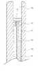
図4は、本発明の一実施例に係る可撓性延性部形状推定装置のプローブを示す断面図である。図4は、本発明の一実施例に係る可撓性延性部形状推定装置100のプローブ10の先端部周辺を示した図である。 FIG. 4 is a cross-sectional view showing a probe of a flexible ductility portion shape estimating device according to an embodiment of the present invention. FIG. 4 is a view showing the periphery of the distal end of the
図4を参照すれば、本発明の一実施例に係る可撓性延性部形状推定装置100のプローブ10は、チューブ外皮部11、トルク伝達ワイヤ13、ワイヤ通路15及びワイヤ固定部17を備える。前述した通り、プローブ10は、内視鏡処置機構挿入部85を通過し、内視鏡挿入部70の内視鏡処置機構通路74に挿入貫通することができる。 Referring to FIG. 4, the
チューブ外皮部11は、チューブ状の管状体(tubular body)に形成され、内部にワイヤ通路15を含む。一例として、前記ワイヤ通路15は、空いていてもよい。 The
トルク伝達ワイヤ13は、前記チューブ外皮部11内部に挿入され、前記ワイヤ通路15に配置される。トルク伝達ワイヤ13の一領域は、前記チューブ外皮部11の内側面に結合され、固定される。トルク伝達ワイヤ13は、チューブ外皮部11の先端に向かって挿入され、チューブ外皮部11の先端周辺でチューブ外皮部11と結合され、固定される。 A
図4に示されるように、チューブ外皮部11の先端内側には、ワイヤ固定部17が形成され、前記ワイヤ固定部17によりトルク伝達ワイヤ13がチューブ外皮部11の先端に固定される。ワイヤ固定部17は、トルク伝達ワイヤ13とチューブ外皮部11とを互いに固定結合させる多様な結合手段で具現され得る。実施例により、チューブ外皮部11の内側面とトルク伝達ワイヤ13と間の摩擦力を低減させるために、ワイヤ通路15に潤滑剤が収容される。前記潤滑剤によって、トルク伝達ワイヤ13がチューブ外皮部11の内側面に当接しなくなるか、チューブ外皮部11の内側面とトルク伝達ワイヤ13と間の摩擦力が低減されるので、トルク伝達ワイヤ13の一端で発生したトルクが途中で損失されることなく、トルク伝達ワイヤ13の他端に正確に伝達される。 As shown in FIG. 4 , a
また、実施例により、チューブ外皮部11の内側面とトルク伝達ワイヤ13と間の摩擦力を低減させるために、前記トルク伝達ワイヤ13の表面に摩擦力低減材質がコーティングされる。一例として、前記摩擦力低減材質は、ポリテトラフルオロエチレン(polytetrafluoroethylene;PTFE)であってもよく、その他にも多様な材質に変更されてもよい。 In addition, according to an embodiment, the surface of the
図5は、本発明の一実施例に係る可撓性延性部形状推定装置のプローブが可撓性延性部に挿入された状態を示す断面図である。 FIG. 5 is a cross-sectional view showing a state in which the probe of the device for estimating the shape of a flexible ductile part according to one embodiment of the present invention is inserted into the flexible ductile part.
図5を参照すれば、内視鏡挿入部70に含まれる可撓性延性部73は、内部に内視鏡処置機構通路74が形成される。図5に示されるように、内視鏡処置機構通路74は先端で外部に連通され得る。図5には示されていないが、図3に示されるように、可撓性延性部73の一端には湾曲部71が形成される。 Referring to FIG. 5, a flexible
プローブ10は、前記内視鏡処置機構通路74に挿入される。プローブ10は、図4を参照して前述したように、チューブ外皮部11、トルク伝達ワイヤ13、ワイヤ通路15及びワイヤ固定部17を備える。 The
図6は、本発明の一実施例に係る可撓性延性部形状推定装置のプローブが挿入された可撓性延性部が曲がった状態を示す断面図である。図6は、曲がった可撓性延性部73内部を通じてプローブ10が挿入される状態を図示する。 FIG. 6 is a cross-sectional view showing a bent state of the flexible ductile part into which the probe of the flexible ductile part shape estimating device according to one embodiment of the present invention is inserted. FIG. 6 illustrates the insertion of
プローブ10が可撓性延性部73内部の内視鏡処置機構通路74を通過しながら曲がるか、捩じれる場合、ワイヤ固定部17周辺のプローブ10先端で発生した回転力がトルク伝達ワイヤ13を介して回転情報測定部20まで伝達される。 When the
制御部50は、回転情報測定部20から入力されたトルク伝達ワイヤ13の他端の回転情報及びプローブ挿入長測定部30から入力されたプローブ挿入長を分析し、前記プローブ10が挿入された可撓性延性部73の形状を推定することができる。ディスプレイ部60は、制御部50から前記可撓性延性部73の推定された形状に関する情報が伝送され、
前記可撓性延性部73の推定された形状を利用者に表示することができる。The
The estimated shape of the flexible
図7は、本発明の別の実施例に係る可撓性延性部形状推定装置を示すブロックダイアグラムである。図7を参照すれば、本発明の別の実施例に係る可撓性延性部形状推定装置200は、プローブ10及び回転情報測定部20を含む。実施例により、前記可撓性延性部形状推定装置200は、プローブ挿入長入力部40、制御部50及びディスプレイ部60をさらに含む。 FIG. 7 is a block diagram illustrating a flexible ductility shape estimator according to another embodiment of the invention. Referring to FIG. 7 , a flexible ductile part
図7に示された本発明の他の実施例に係る可撓性延性部形状推定装置200は、図2を参照して前述したように、本発明の一実施例に係る可撓性延性部形状推定装置100と類似するか、プローブ挿入長測定部30の代わりにプローブ挿入長入力部40を備える差がある。 A flexible
プローブ10は、図1に示された内視鏡装置の可撓性延性部73に挿入される。プローブ10は、一端に作用されるトルクを他端に伝達するトルク伝達ワイヤ13を備える。回転情報測定部20は、プローブ10の他端に結合され、トルク伝達ワイヤ13の他端の回転情報を測定することができる。チューブ外皮部11内部のワイヤ通路15に配置されるトルク伝達ワイヤ13の他端が回転情報測定部20と連結される。プローブ10及び回転情報測定部20は、図2~図6を参照して前述したので、詳細説明は省略する。 The
プローブ挿入長入力部40は、前記プローブ10が内視鏡処置機構挿入部85を通過し、可撓性延性部73に挿入される長さであるプローブ挿入長を、利用者から入力を受けてもよい。利用者は、プローブ10が内視鏡処置機構挿入部85を介して可撓性延性部73内部に挿入されるとき、プローブ10が挿入された長さを見ながら、プローブ挿入長入力部40を介して前記プローブ挿入長を入力することができる。一例として、前記プローブ挿入長入力部40は、ペダル状に形成され、利用者がペダルを踏む回数及び間隔の少なくとも一つを利用し、前記プローブ挿入長を入力することができる。例えば、利用者は、プローブ10が可撓性延性部73内部で所定長さ(例:10cm)だけ・BR>}入されるたびに、前記ペダル状に具現されたプローブ挿入長入力部40を踏むことができる。利用者がプローブ挿入長入力部40を介して入力した信号は、制御部50に伝送される。 The probe insertion
実施例により、プローブ10の外側面に所定長さの間隔でプローブ長さマーカーが表示され、利用者は、前記プローブ長さマーカーを参考にしてプローブ10が可撓性延性部73内部に挿入された長さを判断し、プローブ挿入長入力部40を操作することができる。実施例により、前記プローブ挿入長入力部40は、ペダル状の外にもトグルスイッチ形態、プローブ挿入長を直接数字で入力できるキーパッドなどのプローブ挿入長を入力できる多様な入力手段であってもよい。実施例により、プローブ10が可撓性延性部73の内部で後退する場合には、利用者がプローブ挿入長入力部40を介して前進信号ではない後退信号を入力することができ、これにより、前記プローブ挿入長が減少されるように具現され得る。 According to an embodiment, probe length markers are displayed on the outer surface of the
制御部50は、回転情報測定部20から入力されたトルク伝達ワイヤ13の他端の回転情報及びプローブ挿入長入力部40から入力されたプローブ挿入長を分析し、前記プローブ10が挿入された可撓性延性部73の形状を推定することができる。制御部50は、プローブ挿入長入力部40から入力された信号に応じて、当該信号が入力された時点のプローブ挿入長が分かり、当該プローブ挿入長に対応されるトルク伝達ワイヤ13の他端の回転情報を対応させ、前記プローブ10の形状及び前記プローブ10が挿入された可撓性延性部73の形状を推定することができる。プローブ挿入長入力部40から順次に入力される信号を分析し、当該プローブ挿入長に対応されるトルク伝達ワイヤ13の他端の回転情報を対応させれば、プローブ10が挿入された可撓性延性部73の全体形状を推定できるようになる。実施例により、制御部50は、回転情報測定部20から入力されたトルク伝達ワイヤ13の他端の回転情報を分析し、前記プローブ10が挿入された可撓性延性部73の形状を推定することもできる。この場合、前記プローブ挿入長入力部40は省略されてもよい。 The
ディスプレイ部60は、制御部50から前記可撓性延性部73の推定された形状に関する情報が伝送され、利用者に表示することができる。 Information on the estimated shape of the
実施例により、本発明の他の実施例に係る可撓性延性部形状推定装置200は、プローブ挿入長測定部30及びプローブ挿入長入力部40を同時に具備でき、利用者の選択に応じてプローブ挿入長測定部30及びプローブ挿入長入力部40のいずれか一つを使用することができる。 According to an embodiment, the flexible ductility part
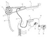
図8は、本発明の別の実施例に係る可撓性延性部形状推定装置の使用状態図である。図7を参照して前述した可撓性延性部形状推定装置200が図8に示されるように具現され得る。図8を参照すれば、本発明の別の実施例に係る可撓性延性部形状推定装置200は、プローブ10、回転情報測定部20、プローブ挿入長入力部40、制御部50及びディスプレイ部60を含む。 FIG. 8 is a usage state diagram of a flexible ductility portion shape estimating device according to another embodiment of the present invention. The flexible
プローブ10は、チューブ状の管状体に形成されてもよく、内視鏡処置機構挿入部85に挿入される。プローブ10は、回転情報測定部20と連結される。プローブ10は、チューブ外皮部11、トルク伝達ワイヤ13及びワイヤ通路15を含む。チューブ外皮部11は、チューブ状に形成され、内部にワイヤ通路15を含む。トルク伝達ワイヤ13は、チューブ外皮部11内部のワイヤ通路15に配置される。前記プローブ10の具体的な特徴及び前記プローブ10が可撓性延性部73に挿入される形態などは、図3~図6を参照して前述した通りであるので、詳細説明は省略する。 The
回転情報測定部20は、プローブ10の他端に結合され、前記トルク伝達ワイヤ13の他端の回転情報を測定することができる。プローブ結合部21を介して前記プローブ10と回転情報測定部20とが互いに連結される。一例として、プローブ10に備えられるトルク伝達ワイヤ13の他端は、プローブ結合部21を通過し、回転情報測定部20内部に配置される。前記トルク伝達ワイヤ13の他端は、回転情報測定部20に備えられるトルクセンサーや回転角センサーと隣接した位置に配置される。回転情報測定部20は、トルク伝達ワイヤ13により発生するトルクを測定するか、前記トルクによって発生するトルク伝達ワイヤ13の回転角を測定することができる。回転情報測定部20と制御部50は、通信線92を介して連結され、データを授受することができる。 The rotation
プローブ挿入長入力部40は、前記プローブ10が内視鏡処置機構挿入部85を通過し、可撓性延性部73に挿入される長さであるプローブ挿入長を、利用者から入力を受けてもよい。図8に示されるように、前記プローブ挿入長入力部40は、ペダル状に形成され、利用者がペダルを踏む回数及び間隔の少なくとも一つを利用し、前記プローブ挿入長を入力することができる。利用者がプローブ挿入長入力部40を介して入力した信号は、制御部50に伝送される。前記回転情報測定部20とプローブ挿入長入力部40とは通信線91を介して連結され、データを授受することができる。一例として、前記プローブ挿入長入力部40は、回転情報測定部20の周辺に配置される。 The probe insertion
実施例により、前記プローブ挿入長入力部40は、ペダル状ではなく別途のトグルスイッチ形態で具現され得る。利用者は、トグルスイッチに具現されたプローブ挿入長入力部40を押し、前記プローブ挿入長を入力することができる。例えば、利用者は、プローブ10が可撓性延性部73内部に所定長さ(例:10cm)だけ挿入されるたびに、前記トグルスイッチを押すことができる。トグルスイッチを介して利用者が入力した信号は、制御部50に伝送される。 Depending on the embodiment, the probe insertion
制御部50は、回転情報測定部20から入力されたトルク伝達ワイヤ13の他端の回転情報及びプローブ挿入長入力部40から入力されたプローブ挿入長を分析し、前記プローブ10が挿入された可撓性延性部73の形状を推定することができる。制御部50は、トルク伝達ワイヤ13の他端のトルク及び回転角の少なくとも一つを分析し、前記トルク伝達ワイヤ13の他端の回転情報を得ることができる。 The
制御部50は、プローブ挿入長入力部40から入力された信号に応じて、当該信号が入力された時点のプローブ挿入長が分かり、当該プローブ挿入長に対応されるトルク伝達ワイヤ13の他端の回転情報を対応させ、前記プローブ10の形状及び前記プローブ10が挿入された可撓性延性部73の形状を推定することができる。プローブ挿入長入力部40から順次に入力される信号を分析し、当該プローブ挿入長に対応されるトルク伝達ワイヤ13の他端の回転情報を対応させれば、プローブ10が挿入された可撓性延性部73の全体形状を推定することができるようになる。制御部50は、プローブ挿入長入力部40から信号を入力された各時点で、トルク伝達ワイヤ13のトルク又は回転角などがどのように変化するかを測定することができる。 The
ディスプレイ部60は、制御部50から前記可撓性延性部73の推定された形状に関する情報が伝送され、前記可撓性延性部73の推定された形状を利用者に表示することができる。ディスプレイ部60は、制御部50から入力された表示信号に応じて画面を表示し、利用者に提供することができる。 The
図9は、本発明の一実施例に係る可撓性延性部形状推定装置を含む内視鏡システムを示すブロックダイアグラムである。図9を参照すれば、本発明の一実施例に係る可撓性延性部形状推定装置を含む内視鏡システム300は、トルク伝達ワイヤ13、回転情報測定部20を含み、実施例により、内視鏡挿入長入力部45、制御部50及びディスプレイ部60をさらに含む。図1~図8を参照して前述した内容は、前記内視鏡システム300の特徴と矛盾しない範囲内で前記内視鏡システム300にも類似に適用することができる。 FIG. 9 is a block diagram showing an endoscope system including a flexible ductility shape estimator according to one embodiment of the present invention. Referring to FIG. 9, an
トルク伝達ワイヤ13は、可撓性延性部73内部に挿入される。可撓性延性部73は、外力により湾曲可能であり、内部にワイヤ通路75を含むことができる。トルク伝達ワイヤ13は、前記ワイヤ通路75に配置され、一端に作用されるトルクを他端に伝達することができる。
回転情報測定部20は、前記トルク伝達ワイヤ13の他端に結合され、トルク伝達ワイヤ13の他端の回転情報を測定することができる。回転情報測定部20は、トルク伝達ワイヤ13の他端のトルクを測定するトルクセンサー及びトルク伝達ワイヤ13の他端の回転角を測定する回転角センサーの少なくとも一つを含むことができる。 The rotation
内視鏡挿入長入力部45は、可撓性延性部73を含む内視鏡挿入部70が被術者の身体に挿入される長さである内視鏡挿入長を、利用者から入力を受けてもよい。一例として、
前記内視鏡挿入長入力部45は、ペダル状に形成され、利用者が前記ペダルを踏む回数及び間隔の少なくとも一つを利用し、前記内視鏡挿入長を入力することができる。実施例により、前記内視鏡挿入長入力部45は、前述したプローブ挿入長入力部40と類似してもよく、多様に変更されてもよい。The endoscope insertion
The endoscope insertion
制御部50は、前記回転情報測定部20から入力されたトルク伝達ワイヤ13の他端の回転情報及び前記内視鏡挿入長入力部45から入力された内視鏡挿入長を分析し、前記可撓性延性部73の形状を推定することができる。実施例により、制御部50は、回転情報測定部20から入力されたトルク伝達ワイヤ13の他端の回転情報を分析し、前記トルク伝達ワイヤ13が挿入された可撓性延性部73の形状を推定することもできる。この場合、前記内視鏡挿入長入力部45は省略することもできる。 The
ディスプレイ部60は、前記制御部50から前記可撓性延性部73の推定された形状に関する情報が伝送され、前記可撓性延性部73の推定された形状を利用者に表示することができる。 The
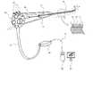
図10は、本発明の一実施例に係る可撓性延性部形状推定装置を含む内視鏡システムを示す図である。図9を参照して、前述した本発明の一実施例に係る可撓性延性部形状推定装置を含む内視鏡システム300は、図10に示されるように具現され得る。図10を参照すれば、本発明の一実施例に係る可撓性延性部形状推定装置を含む内視鏡システム300は、内視鏡挿入部70及び内視鏡操作部80を備える。実施例により、前記内視鏡システム300は、制御部50、内視鏡モニタリング装置55、ディスプレイ部60及びユニバーサルコード90等をさらに含む。 FIG. 10 is a diagram showing an endoscope system including a flexible ductile portion shape estimator according to one embodiment of the present invention. Referring to FIG. 9, an
内視鏡挿入部70は、内視鏡操作部80の一領域に結合され、被検体内に挿入される。
内視鏡挿入部70は、湾曲が自由な湾曲部71及び外力により簡単に曲げられ、円状に回復することができる可撓性を有する可撓性延性部73を含む。可撓性延性部73は、内部にワイヤ通路75を含む。前記ワイヤ通路75は、内視鏡挿入部70の内部に形成され、
内視鏡処置機構挿入部85と連通する内視鏡処置機構通路74と異なる通路であってもよい。図10に示されていなが、内視鏡挿入部70の内部には、内視鏡処置機構挿入部85と連通する内視鏡処置機構通路74が形成される。湾曲部71の一端には、観察窓や照明窓、処置具挿通チャネル開口部、送気・送水ノズルなどが配置される。The
The
It may be a passage different from the endoscope
図10に示されるように、トルク伝達ワイヤ13は、可撓性延性部73内部に挿入される。トルク伝達ワイヤ13は、前記ワイヤ通路75に配置され、一端に作用されるトルクを他端に伝達することができる。トルク伝達ワイヤ13の他端は、回転情報測定部20と連結され得る。 As shown in FIG. 10,
回転情報測定部20は、前記トルク伝達ワイヤ13の他端に結合され、トルク伝達ワイヤ13の他端の回転情報を測定することができる。回転情報測定部20は、内視鏡操作部80の内部に配置される。回転情報測定部20は、トルク伝達ワイヤ13の他端のトルクを測定するトルクセンサー及びトルク伝達ワイヤ13の他端の回転角を測定する回転角センサーの少なくとも一つを含む。トルク伝達ワイヤ13の他端は、回転情報測定部20に備えられるトルクセンサーや回転角センサーと隣接した位置に配置される。回転情報測定部20は、トルク伝達ワイヤ13の他端の回転情報を、ユニバーサルコード90を介して内視鏡モニタリング装置55及び制御部50に伝送することができる。 The rotation
内視鏡操作部80は、内視鏡挿入部70とユニバーサルコード90と間に形成される。内視鏡操作部80は、湾曲操作レバー81及び操作スイッチ部83を含み、側面に内視鏡処置機構挿入部85をさらに含む。 The
内視鏡挿入長入力部(図9の45)は、可撓性延性部73を含む内視鏡挿入部70が被術者の身体に挿入される長さである内視鏡挿入長を、利用者から入力を受けてもよい。利用者は、内視鏡挿入部70が被術者の身体内部に挿入されるとき、内視鏡挿入部70が挿入された長さを見ながら内視鏡挿入長入力部(図9の45)を介して前記内視鏡挿入長を入力することができる。前記内視鏡挿入長入力部(図9の45)は、湾曲操作レバー81又は操作スイッチ部83に形成される。内視鏡挿入長入力部(図9の45)は、トグルスイッチ形態に具現されてもよく、利用者はトグルスイッチに具現された内視鏡挿入長入力部45を押し、前記内視鏡挿入長を入力することができる。例えば、利用者は、内視鏡挿入部70が被術者の身体内部で所定長さ(例:10cm)だけ挿入されるたびに、前記トグルスイッチを押すことができる。トグルスイッチを介して利用者が入力した信号は、ユニバーサルコード90及び通信線91を介して内視鏡モニタリング装置55及び制御部50に伝送することができる。 The endoscope insertion length input section (45 in FIG. 9) inputs the endoscope insertion length, which is the length at which the
実施例により、内視鏡挿入部70外側面に所定長さ間隔で内視鏡長さマーカーが表示され、利用者は、前記内視鏡長さマーカーを参考にし、内視鏡挿入部70が被術者の身体内部に挿入された長さを判断し、内視鏡挿入長入力部(図9の45)を操作することができる。 According to the embodiment, endoscope length markers are displayed at predetermined intervals on the outer surface of the
実施例により、前記内視鏡挿入長入力部45は、図8に示されるように、ペダル状に形成され、利用者が前記ペダルを踏む回数及び間隔の少なくとも一つを利用し、前記内視鏡挿入長を入力することができる。実施例により、前記内視鏡挿入長入力部45は、ペダル状やトグルスイッチの以外にも内視鏡挿入長を直接数字で入力することができるキーパッドなど内視鏡挿入長を入力できる様々な入力手段で具現され得る。実施例により、内視鏡挿入部70が被術者の身体内部で後退する場合には、利用者が内視鏡挿入長入力部45を介して前進信号ではない後退信号を入力することができ、これにより、前記内視鏡挿入長が減少されるように具現することができる。 According to an embodiment, the endoscope insertion
ユニバーサルコード90は、内視鏡操作部80の一領域に結合され、内視鏡のカメラ又は光源装置のための伝送コード、送気管、送水管、吸入管などを内部に含む。前記伝送コード、送気管、送水管及び吸入管などは、内視鏡操作部80の内部を通過し、内視鏡挿入部70まで伸びることができる。内視鏡挿入部70の内部には、伝送コード、送気管、送水管及び吸入管などが通過可能な通路(channel)が形成される。ユニバーサルコード90の他端は、内視鏡モニタリング装置55に連結される。 The
内視鏡モニタリング装置55は、内視鏡の光源装置や送気、送水、吸入管及び内視鏡の電磁気的な状況をモニタリングすることができる。内視鏡モニタリング装置55は、通信線91を介して制御部50と連結される。内視鏡モニタリング装置55によりモニタリングされた内視鏡関連情報は、ディスプレイ部60を介して利用者に提供される。実施例により、前記内視鏡モニタリング装置55は、省略することができる。 The
制御部50は、回転情報測定部20から入力されたトルク伝達ワイヤ13の他端の回転情報及び内視鏡挿入長入力部45から入力された内視鏡挿入長を分析し、前記トルク伝達ワイヤ13が挿入された可撓性延性部73の形状を推定することができる。制御部50は、トルク伝達ワイヤ13の他端のトルク及び回転角の少なくとも一つを分析し、前記トルク伝達ワイヤ13の他端の回転情報を得ることができる。 The
制御部50は、内視鏡挿入長入力部45から入力された信号に応じて、当該信号が入力された時点の内視鏡挿入長が分かり、当該内視鏡挿入長に対応されるトルク伝達ワイヤ13の他端の回転情報を対応させ、前記トルク伝達ワイヤ13の形状及び前記トルク伝達ワイヤ13が挿入された可撓性延性部73の形状を推定することができる。内視鏡挿入長入力部45から順次に入力される信号を分析し、当該内視鏡挿入長に対応されるトルク伝達ワイヤ13の他端の回転情報を対応させれば、トルク伝達ワイヤ13が挿入された可撓性延性部73の全体形状を推定することができるようになる。制御部50は、内視鏡挿入長入力部45から信号を入力された各時点で、トルク伝達ワイヤ13のトルク又は回転角がどのように変化するかを測定することができる。 The
実施例により、制御部50は、回転情報測定部20から入力されたトルク伝達ワイヤ13の他端の回転情報を分析し、前記トルク伝達ワイヤ13が挿入された可撓性延性部73の形状を推定することもできる。この場合、前記内視鏡挿入長入力部45は省略することができる。 According to an embodiment, the
ディスプレイ部60は、前記制御部50から前記可撓性延性部73の推定された形状に関する情報が伝送され、利用者に表示することができる。ディスプレイ部60は、制御部50から入力された表示信号に応じて画面を表示し、利用者に提供することができる。 The
一方、図10には、内視鏡モニタリング装置55、制御部50及びディスプレイ部60が互いに分離された形態で示されているが、これは例示的なであり、内視鏡モニタリング装置55、制御部50及びディスプレイ部60等は、一つの本体に統合されてもよい。また、前記通信線91は変更又は省略することができ、実施例により、内視鏡モニタリング装置55及び制御部50等は、無線通信方式を介してデータを授受することができる。 On the other hand, although FIG. 10 shows the
図10に示された本発明の一実施例に係る可撓性延性部形状推定装置を含む内視鏡システム300は、内視鏡挿入部70の内部に形成されるワイヤ通路75を介してトルク伝達ワイヤ13を挿入し、前記可撓性延性部73の先端部位に前記トルク伝達ワイヤ13が固定される。 An
可撓性延性部73が被検体の内部に挿入され、前進するとき、可撓性延性部73の進行方向で抵抗が発生する場合、可撓性延性部73の長軸がスプリングのコイルのように曲がり、これにより、発生した弾性エネルギーの一部が前記可撓性延性部73の長軸を中心にトルクを発生させることができる。このようなトルクによって可撓性延性部73が長軸を中心に回転することになる。 When the flexible
可撓性延性部73の先端に、トルク伝達ワイヤ13の一端が固定されることがあるので
、可撓性延性部73が曲がるか、捩じれにより発生するトルクは、トルク伝達ワイヤ13を介して回転情報測定部20に伝達される。回転情報測定部20は、トルク伝達ワイヤ13の他端のトルク又はトルク伝達ワイヤ13の他端の回転角を測定することができる。回転情報測定部20で測定されたトルク伝達ワイヤ13の他端の回転情報は、ユニバーサルコード90を介して内視鏡モニタリング装置55及び制御部50の少なくとも一つに伝送され、内視鏡モニタリング装置55及び制御部50の少なくとも一つは、可撓性延性部73の曲がり、捩じれによる形状変化を推定することができる。Since one end of the
一方、内視鏡挿入部70の可撓性延性部73が内視鏡の長軸方向に進むとき、可撓性延性部73の先端部が前進しない場合には、可撓性延性部73の先端以外の部分が曲がるか、捩じれることになり、このように曲がるか、捩じれた部位を特定し難いこともある。 On the other hand, when the flexible
内視鏡操作部80の操作スイッチ部83等に内視鏡挿入長入力部(図9の45)が具現されれば、前述のような場合、内視鏡挿入部70が被検体内で前方に向かって前進する前と一定の距離を前進した後の瞬間を前記内視鏡挿入長入力部(図9の45)を利用し、回転情報測定部20に伝達することができる。回転情報測定部20は、内視鏡挿入部70が被検体内で前方に向かって前進する前と一定の距離を前進した後の瞬間のトルク伝達ワイヤ13の回転角の変化を測定することができる。 If an endoscope insertion length input section (45 in FIG. 9) is implemented in the
可撓性延性部73の捩じれによるトルク伝達ワイヤ13の回転情報と前記可撓性延性部73が被検体内で前進した距離は、可撓性延性部73の形状変化と一貫した関係を有することになる。即ち、可撓性延性部73が被検体内で前進した単位距離当たりトルク伝達ワイヤ13に伝送されるトルクの変化又は可撓性延性部73が被検体内で前進した単位距離当たりトルク伝達ワイヤ13の回転による回転角の変化が大きいほど前記可撓性延性部73の捩じれの程度は増大加することになる。 The rotational information of the
これを利用して制御部50は、可撓性延性部73が曲がるか、ねじりによる形状変化を推定することができる。制御部50は、トルク伝達ワイヤ13の回転角の変化を利用し、
可撓性延性部73先端の単位距離移動に対する捩じれの程度を推定することができる。制御部50は、推定された可撓性延性部73の形状を、ディスプレイ部60を介して利用者に提供することができる。Using this, the
The degree of twist for a unit distance movement of the tip of the flexible
一方、実施例により、前記トルク伝達ワイヤ13の他端に結合される金属棒(未図示)をさらに含む。前記金属棒は、回転情報測定部20に連結され、回転情報測定部20は、
金属棒の回転角及びトルクの少なくとも一つを測定し、トルク伝達ワイヤ13の他端の回転情報を測定することができる。トルク伝達ワイヤ13の他端の回転情報を直接測定し難い場合、トルク伝達ワイヤ13の他端に結合される金属棒の回転情報を測定し、トルク伝達ワイヤ13の他端の回転情報を間接的に測定することができる。Meanwhile, according to an embodiment, a metal rod (not shown) coupled to the other end of the
By measuring at least one of the rotation angle and torque of the metal rod, the rotation information of the other end of the
一方、実施例により、本発明の一実施例に係る可撓性延性部形状推定装置を含む内視鏡システム300は、内視鏡挿入部70が被検体内部で前進するとき、前記内視鏡挿入部70と関連している内視鏡挿入長測定部(未図示)が内視鏡挿入部70の挿入長を測定することができる。一例として、前記内視鏡挿入長測定部は、被検体に挿入される内視鏡挿入部70の周辺又は内視鏡挿入部70が挿入される被術者の身体部位周辺に配置される。内視鏡挿入長測定部は、内視鏡挿入部70が被術者の身体に挿入される長さである内視鏡挿入長を測定することができる。実施例により、内視鏡挿入長測定部は、プローブ挿入長測定部30と同様に回転式ローラーや、レーザー、超音波などを利用して具現することができる。 On the other hand, according to an embodiment, the
実施例により、前記内視鏡挿入長測定部は、内視鏡挿入部70の外側面に所定間隔で備えられる複数個の圧力センサー(未図示)を含む。一例として、前記複数個の圧力センサーは、内視鏡挿入部70の外側面に10cm置きに配置される。複数個の圧力センサーは、内視鏡挿入部70が被術者の身体(例:肛門)内部で前進するときに発生する圧力の差を感知し、制御部50に伝送することができる。制御部50は、複数個の圧力センサーから伝送された圧力感知信号を利用し、内視鏡挿入部70のある位置まで被術者の身体内部に挿入されたかを分析することができる。このような方式で内視鏡挿入部70が被術者の身体に挿入される長さである内視鏡挿入長が測定されることができる。 According to an embodiment, the endoscope insertion length measuring unit includes a plurality of pressure sensors (not shown) provided on the outer surface of the
また、実施例により、前記内視鏡挿入長測定部は、内視鏡挿入部70の一領域に配置される温度センサー(未図示)を含む。一例として、前記温度センサーは、内視鏡挿入部70の湾曲部71の外側面に配置されるか、可撓性延性部73の先端部の外側面に配置される。前記温度センサーは、内視鏡挿入部70が被術者の身体内部に挿入されれば、被術者の体温によって内視鏡挿入部70周辺の温度が高くなる原理を利用するものである。前記温度センサーで感知された温度情報は、制御部50に伝送される。制御部50は、前記温度センサーによって感知された体温が高くなるほど内視鏡挿入部70が被術者の身体内部に深く挿入されたと判断し、前記内視鏡挿入長を推定することができる。 Also, according to an embodiment, the endoscope insertion length measuring unit includes a temperature sensor (not shown) disposed in a region of the
実施例により、前記内視鏡挿入長測定部は、有線又は無線で制御部50と連結される。前記内視鏡挿入長測定部は、被術者の身体一領域に付着し、内視鏡挿入長を測定することができる。制御部50は、前記回転情報測定部20から入力されたトルク伝達ワイヤ13の他端の回転情報及び前記内視鏡挿入長測定部から入力された内視鏡挿入長を分析し、前記可撓性延性部73の形状を推定することができる。 Depending on the embodiment, the endoscope insertion length measuring unit is connected to the
実施例により、本発明の一実施例に係る可撓性延性部形状推定装置を含む内視鏡システム300は、内視鏡挿入長測定部及び内視鏡挿入長入力部45を同時に具備することができ、利用者が選択に応じて内視鏡挿入長測定部及び内視鏡挿入長入力部45のいずれか一つを使用することができる。
図11は本発明の一実施例に係る可撓性延性部形状推定装置を含む内視鏡システムの可撓性延性部を示す断面図である。図11は、本発明の一実施例に係る可撓性延性部形状推定装置を含む内視鏡システム300の可撓性延性部73の先端部周辺を示したものである。図11に示されていないが、図10に示された通りに、可撓性延性部73の一端には、湾曲部71が形成される。According to an embodiment, an
FIG. 11 is a cross-sectional view showing a flexible ductile part of an endoscope system including a flexible ductile part shape estimating device according to an embodiment of the present invention. FIG. 11 shows the periphery of the distal end portion of the flexible
図11を参照すれば、チューブ状の管状体に形成される可撓性延性部73の内部にワイヤ通路75が形成される。一例として、前記ワイヤ通路15は空いていてもよい。 Referring to FIG. 11, a
トルク伝達ワイヤ13は、可撓性延性部73の内部に挿入され、前記ワイヤ通路75に配置される。トルク伝達ワイヤ13の一領域は、前記可撓性延性部73の内側面に結合され、固定される。トルク伝達ワイヤ13は、可撓性延性部73の先端に向かって挿入され、可撓性延性部73の先端周辺で可撓性延性部73と結合され、固定される。 A
図11に示されるように、可撓性延性部73の先端内側には、ワイヤ固定部17が形成され、前記ワイヤ固定部17によりトルク伝達ワイヤ13が可撓性延性部73の内側に固定される。ワイヤ固定部17は、トルク伝達ワイヤ13と可撓性延性部73とを互いに固定結合することができる様々な結合手段に具現される。 As shown in FIG. 11 , a
実施例により、可撓性延性部73の内側面とトルク伝達ワイヤ13と間の摩擦力を低減させるために、ワイヤ通路75に潤滑剤が収容される。前記潤滑剤によってトルク伝達ワイヤ13が可撓性延性部73の内側面に当接しなくなるか、可撓性延性部73の内側面とトルク伝達ワイヤ13と間の摩擦力が低減されるので、トルク伝達ワイヤ13の一端で発生したトルクが途中で損失されることなく、トルク伝達ワイヤ13の他端に正確に伝達される。 According to an embodiment, a lubricant is contained in the
また、実施例により、可撓性延性部73の内側面とトルク伝達ワイヤ13と間の摩擦力を低減させるために、前記トルク伝達ワイヤ13の表面に摩擦力低減材質がコーティングされてもよい。一例として、前記摩擦力低減材質は、ポリテトラフルオロエチレン(polytetrafluoroethylene;PTFE)であってもよく、その他にも様残な材質に変更されてもよい。 Also, according to an embodiment, the surface of the
図12は、本発明の一実施例に係る可撓性延性部形状推定装置を含む内視鏡システムの可撓性延性部が曲がった状態を示す図である。図12は、ワイヤ固定部17により可撓性延性部73の内側にトルク伝達ワイヤ13の一端が固定され、可撓性延性部73が曲がるにつれてトルク伝達ワイヤ13も同じく曲がる可能性があることを示している。 FIG. 12 is a diagram showing a bent state of the flexible ductile part of the endoscope system including the flexible ductile part shape estimating device according to one embodiment of the present invention. FIG. 12 shows that the
内視鏡挿入部70が被検体の内部に挿入され、可撓性延性部73が曲がるか、捩じれる場合、ワイヤ固定部17周辺の可撓性延性部73の先端で発生した回転力がトルク伝達ワイヤ13を介して回転情報測定部20まで伝達される。 When the
制御部50は、回転情報測定部20から入力されたトルク伝達ワイヤ13の他端の回転情報及び内視鏡挿入長入力部45から入力された内視鏡挿入長を分析し、前記可撓性延性部73の形状を推定することができる。ディスプレイ部60は、制御部50から前記可撓性延性部73の推定された形状に関する情報が伝送され、前記可撓性延性部73の推定された形状を利用者に表示することができる。 The
図13~図15は、本発明の一実施例に係る可撓性延性部の形状変化推定原理を説明する図である。 13 to 15 are diagrams for explaining the shape change estimation principle of the flexible ductile portion according to one embodiment of the present invention.
図13を参照すれば、本発明の一実施例に係る可撓性延性部の形状変化推定原理を説明するための可撓性延性部モデルPが示されている。前記可撓性延性部モデルPは、内視鏡のように線形からなり、湾曲可能であってもよい。図13は、前記可撓性延性部モデルPが曲がるか、捩じれる現象を引き起こさない場合を示す。 Referring to FIG. 13, a flexible ductility model P for explaining the shape change estimation principle of the flexible ductility according to one embodiment of the present invention is shown. The flexible ductility model P may be linear and bendable like an endoscope. FIG. 13 shows the case where the flexible ductility model P does not bend or twist.
可撓性延性部モデルPは、特定の多角形(例:三角形)の物質が可撓性延性部(flexible portion)の長軸に沿って一貫して含まれる。可撓性延性部モデルPの左側端面及び右側端面に前記多角形A1、A2が表示される。可撓性延性部モデルPの捩じれる現象を示すマーカーBが可撓性延性部モデルPの外側面に表示される。 The flexible ductile model P contains a specific polygonal (eg, triangular) shape of material consistently along the long axis of the flexible portion. The polygons A1 and A2 are displayed on the left end surface and the right end surface of the flexible ductile part model P, respectively. A marker B indicating the twisting phenomenon of the flexible ductile part model P is displayed on the outer surface of the flexible ductile part model P. FIG.
図14は、可撓性延性部モデルが時計回りに1回転した状態を示す図である。 FIG. 14 is a diagram showing a state in which the flexible ductility model rotates clockwise once.
前記可撓性延性部モデルPの長軸に沿って特定の多角形の物質が一貫して含まれているので、可撓性延性部モデルPに沿ってどの端面を切断してみても特定の多角形の物質が含まれた同じパターンの端面が示されることが分かる。 Since a specific polygonal material is consistently included along the long axis of the flexible ductile part model P, no matter which end face is cut along the flexible ductile part model P, a specific polygonal material is included. It can be seen that the same pattern of endfaces containing polygonal material is shown.
図14に示されるように、可撓性延性部モデルPが時計回りに1回転した状態で中間部位の端面を切断してみると、二つの捩じれた形状の2個の可撓性延性部モデルP1、P2に分けられる。 As shown in FIG. 14, when the end surface of the intermediate portion is cut while the flexible ductile part model P is rotated clockwise, two flexible ductile part models of two twisted shapes are obtained. It is divided into P1 and P2.
第1可撓性延性部モデルP1の左側に露出される多角形A11は、空間上の3点で形成され、各点の3次元座標は、それぞれ(a、b、c)、(d、e、f)、(g、h、i)であってもよい。このような空間の3点からなる多角形が可撓性延性部モデルP1、P2の長軸に沿って一貫して含まれているので、第1可撓性延性部モデルP1の右側に露出される多角形A12も第1可撓性延性部モデルP1の左側に露出される多角形A11と同じ形状であってもよい。第1可撓性延性部モデルP1の右側に露出される多角形A12をなす各点の3次元座標は、それぞれ(a1、b1、c1)、(d1、e1、f1)、(g1
、h1、i1)であってもよい。図14に示されるように、第2可撓性延性部モデルP2の左側に露出される多角形A21をなす3点は、第1可撓性延性部モデルP1の右側に露出される多角形A12をなす3点と同じ空間上の座標を有することができる。第2可撓性延性部モデルP2の右側に露出される多角形A22をなす各点の3次元座標は、それぞれ(a2、b2、c2)、(d2、e2、f2)、(g2、h2、i2)であってもよい。The polygon A11 exposed on the left side of the first flexible ductile part model P1 is formed by three points in space, and the three-dimensional coordinates of each point are (a, b, c), (d, e , f), (g, h, i). Since such a spatial three-point polygon is consistently included along the long axis of the flexible ductility model P1, P2, it is exposed on the right side of the first flexible ductility model P1. The polygon A12 may also have the same shape as the polygon A11 exposed on the left side of the first flexible ductile part model P1. The three-dimensional coordinates of the points forming the polygon A12 exposed on the right side of the first flexible ductile part model P1 are (a1, b1, c1), (d1, e1, f1), (g1
, h1, i1). As shown in FIG. 14, three points forming a polygon A21 exposed on the left side of the second flexible ductile part model P2 correspond to a polygon A12 exposed on the right side of the first flexible ductile part model P1. can have the same spatial coordinates as the three points forming The three-dimensional coordinates of each point forming the polygon A22 exposed on the right side of the second flexible ductile part model P2 are (a2, b2, c2), (d2, e2, f2), (g2, h2, i2).
2個の可撓性延性部モデルP1、P2が互いに連結されるとき、第1可撓性延性部モデルP1の右側に存在する多角形A12と第2可撓性延性部モデルP2の左側に存在する多角形A21とを互いに同じ空間で一致するように整列させれば、2つのそれぞれ異なる可撓性延性部モデルP1、P2の接合されたことを2次元空間や3次元空間で示すことができるようになる。 When the two flexible ductile part models P1 and P2 are connected to each other, the polygon A12 existing on the right side of the first flexible ductile part model P1 and the polygon A12 existing on the left side of the second flexible ductile part model P2 By aligning the two polygons A21 so as to match each other in the same space, it is possible to show in two-dimensional space or three-dimensional space that the two different flexible ductile part models P1 and P2 are joined. become.
それぞれの可撓性延性部モデルP1、P2の左右両端の回転情報を測定すれば、可撓性延性部モデルP1、P2のそれぞれが、特定の方向にどの程度回転したのかが分かる。また、可撓性延性部モデルP1、P2は、長軸に沿って物理的性質が同じであると仮定すれば、それぞれの可撓性延性部モデルP1、P2の左右両端の回転情報を利用し、それぞれの可撓性延性部モデルP1、P2の左右両端を除いた残りの部分の回転情報も推定することができる。このようなそれぞれの可撓性延性部モデルP1、P2の捩じれの程度によって、全可撓性延性部モデルPの形状変化を3次元モデリング方法で3次元表面の数学的表現で示すことができ、これを利用し、それぞれ異なる形状を有するそれぞれの可撓性延性部モデルP1、P2を接合し、2次元空間や3次元空間で示すことができるようになる。 By measuring the rotation information of the left and right ends of each of the flexible ductile part models P1 and P2, it is possible to know how much each of the flexible ductile part models P1 and P2 has rotated in a specific direction. In addition, assuming that the flexible ductility models P1 and P2 have the same physical properties along the long axis, the rotation information of the left and right ends of the respective flexible ductility models P1 and P2 is used. , the rotation information of the remaining portions excluding the left and right ends of each flexible ductility model P1, P2 can also be estimated. According to the degree of torsion of each flexible ductile part model P1, P2, the shape change of the total flexible ductile part model P can be represented by a three-dimensional surface mathematical expression by a three-dimensional modeling method, Using this, the flexible ductile part models P1 and P2 having different shapes can be joined and displayed in a two-dimensional space or a three-dimensional space.
制御部50は、前述した原理でトルク伝達ワイヤ13他端の回転情報が入力される瞬間のプローブ挿入長又は内視鏡挿入長により、プローブ10又は可撓性延性部73の形状を推定することができる。 The
図15は、それぞれ異なる形状を有する可撓性延性部モデルを接合し、2次元空間や3次元空間に表示した図である。 15A and 15B are diagrams in which flexible ductility models having different shapes are joined and displayed in a two-dimensional space or a three-dimensional space.
図15を参照すれば、前述したように、複数個の可撓性延性部モデルP1、P2、P3、P4が互いに接合され、それぞれの可撓性延性部モデルP1、P2、P3、P4の回転情報を測定することによって、全体可撓性延性部モデルの形態を推定できることになる。 Referring to FIG. 15, as described above, a plurality of flexible ductility models P1, P2, P3, P4 are joined together, and the respective flexible ductility models P1, P2, P3, P4 are rotated. By measuring the information, it will be possible to estimate the morphology of the global flexible ductility model.
ディスプレイ部60は、制御部50の制御により図15と類似した形態で可撓性延性部73の形態を推定し、表示することができる。ディスプレイ部60は、可撓性延性部73の推定された形状を2次元や3次元イメージで表示することができる。 The
本発明は、図面に示された実施例を参考して説明したが、これは例示的なものに過ぎなく、本技術分野の通常の知識を有した者であれば、それらから多様な変形及び均等の他の実施例が可能であることを理解できるであろう。従って、本発明の真の技術的保護範囲は、添付された特許請求範囲の技術的思想によって決められる。 Although the present invention has been described with reference to the embodiments shown in the drawings, which are illustrative only, many variations and modifications can be made therefrom by those of ordinary skill in the art. It will be appreciated that other equivalent implementations are possible. Therefore, the true technical scope of protection of the present invention is determined by the technical ideas of the attached claims.
Claims (20)
Translated fromJapanese前記プローブの他端に結合され、前記トルク伝達ワイヤの他端の回転情報を測定する回転情報測定部;を含み、
前記プローブは、チューブ状に形成され、内部にワイヤ通路を含むチューブ外皮部をさらに含み、
前記トルク伝達ワイヤは、前記チューブ外皮部の内部に挿入され、前記ワイヤ通路に配置され、前記トルク伝達ワイヤの前記一端は、前記チューブ外皮部の先端周辺の内側面に結合され、固定される
ことを特徴とする可撓性延性部形状推定装置。A probe having a torque transmission wire that transmits torque applied to one end to the other end and inserted into the flexible ductile part; rotation information measuring unit;
The probe further includes a tubular skin portion formed in a tubular shape and including a wire passage therein,
The torque transmission wire is inserted inside the tube skin and arranged in the wire passage, and theone end of the torque transmission wire is coupled and fixed to the inner surfacearound the tip of the tube skin. A flexible ductile part shape estimation device characterized by:
ことを特徴とする請求項1に記載の可撓性延性部形状推定装置。The flexible wire according to claim 1, wherein the torque transmission wire is inserted toward the tip of the tube jacket, and is coupled and fixed to the tube jacket around the tip of the tube jacket. A device for estimating the shape of a ductile part.
前記トルク伝達ワイヤの他端のトルクを測定するトルクセンサー;及び前記トルク伝達ワイヤの他端の回転角を測定する回転角センサー;の少なくとも一つを含む
ことを特徴とする請求項1に記載の可撓性延性部形状推定装置。The rotation information measuring unit
2. The apparatus according to claim 1, further comprising at least one of a torque sensor for measuring the torque of the other end of the torque transmission wire; and a rotation angle sensor for measuring the rotation angle of the other end of the torque transmission wire. Flexible ductility shape estimator.
前記トルク伝達ワイヤの他端の回転情報を測定することを特徴とする請求項1に記載の可撓性延性部形状推定装置。the probe further includes a metal rod coupled to the other end of the torque transmission wire, the rotation information measuring unit measures at least one of a rotation angle and torque of the metal rod;
2. The flexible ductile part shape estimating device according to claim 1, wherein rotation information of the other end of said torque transmission wire is measured.
前記回転情報測定部から入力された前記トルク伝達ワイヤの他端の回転情報を分析し、前記プローブが挿入された可撓性延性部の形状を推定する制御部;及び
前記制御部から前記可撓性延性部の推定された形状に関する情報が伝送され、利用者に
表示するディスプレイ部;
をさらに含む
ことを特徴とする請求項1に記載の可撓性延性部形状推定装置。The flexible ductility portion shape estimation device includes:
a control unit that analyzes the rotation information of the other end of the torque transmission wire input from the rotation information measurement unit and estimates the shape of the flexible ductility part into which the probe is inserted; a display to which information about the estimated shape of the ductile part is transmitted and displayed to the user;
The flexible ductility shape estimator of claim 1, further comprising:
内視鏡処置機構挿入部の周辺に配置され、前記プローブが前記内視鏡処置機構挿入部を通過し、前記可撓性延性部に挿入される長さであるプローブ挿入長を測定するプローブ挿入長測定部をさらに含む
ことを特徴とする請求項1に記載の可撓性延性部形状推定装置。The flexible ductility portion shape estimation device includes:
A probe insertion device arranged around an endoscope treatment mechanism insertion section for measuring a probe insertion length, which is the length of the probe inserted into the flexible ductile section after passing through the endoscope treatment mechanism insertion section. The flexible ductility shape estimator of claim 1, further comprising a length measuring unit.
前記回転情報測定部から入力された前記トルク伝達ワイヤの他端の回転情報及び前記プローブ挿入長測定部から入力されたプローブ挿入長を分析し、前記プローブが挿入された可撓性延性部の形状を推定する制御部;及び
前記制御部から前記可撓性延性部の推定された形状に関する情報が伝送され、利用者に表示するディスプレイ部;
をさらに含む
ことを特徴とする請求項6に記載の可撓性延性部形状推定装置。The flexible ductility portion shape estimation device includes:
Analyze the rotation information of the other end of the torque transmission wire input from the rotation information measurement unit and the probe insertion length input from the probe insertion length measurement unit, and analyze the shape of the flexible ductility part into which the probe is inserted. a control unit for estimating the; and a display unit for transmitting information about the estimated shape of the flexible ductile part from the control unit and displaying it to a user;
The flexible ductility shape estimator of claim 6, further comprising:
前記プローブが内視鏡処置機構挿入部を通過し、前記可撓性延性部に挿入される長さであるプローブ挿入長を、利用者から入力を受けるプローブ挿入長入力部をさらに含む
ことを特徴とする請求項1に記載の可撓性延性部形状推定装置。The flexible ductility portion shape estimation device includes:
further comprising a probe insertion length input section for receiving an input from a user of a probe insertion length, which is a length by which the probe passes through the endoscope treatment mechanism insertion section and is inserted into the flexible ductile section. The flexible ductility part shape estimation device according to claim 1.
ペダル状に形成され、前記利用者が前記ペダル状のプローブ挿入長入力部を踏む回数及び間隔の少なくとも一つを用いて前記プローブ挿入長を入力する
ことを特徴とする請求項8に記載の可撓性延性部形状推定装置。The probe insertion length input section
9. The probe according to claim 8, which is formed in a pedal shape, and the user inputs the probe insertion length using at least one of the number of times and intervals of stepping on the pedal-shaped probe insertion length input unit. Flexible ductile part shape estimation device.
前記回転情報測定部から入力された前記トルク伝達ワイヤの他端の回転情報及び前記プローブ挿入長入力部から入力されたプローブ挿入長を分析し、前記プローブが挿入された可撓性延性部の形状を推定する制御部;及び
前記制御部から前記可撓性延性部の推定された形状に関する情報が伝送され、利用者に表示するディスプレイ部をさらに含む
ことを特徴とする請求項8に記載の可撓性延性部形状推定装置。The flexible ductility portion shape estimation device includes:
Analyzing the rotation information of the other end of the torque transmission wire input from the rotation information measuring unit and the probe insertion length input from the probe insertion length input unit, and analyzing the shape of the flexible ductility part into which the probe is inserted and a display unit for transmitting information about the estimated shape of the flexible ductile part from the control part and displaying it to a user. Flexible ductile part shape estimation device.
前記可撓性延性部の内部に挿入され、前記ワイヤ通路に配置され、前記可撓性延性部の先端に向かって挿入された一端に作用されるトルクを他端に伝達するトルク伝達ワイヤ;及び
前記トルク伝達ワイヤの他端に結合され、前記トルク伝達ワイヤの他端の回転情報を測定する回転情報測定部;を含み、
前記トルク伝達ワイヤの前記一端は、前記可撓性延性部の先端周辺の内側面に結合され、固定される
ことを特徴とする可撓性延性部形状推定装置を含む内視鏡システム。a flexible ductile portion that is bendable by an external force and contains a wire passageway therein;
a torque transmission wire that is inserted inside the flexible ductile portion, arranged in the wire passage, and transmits torque applied to one endinserted toward the tip of the flexible ductile portion to the other end; and a rotation information measuring unit coupled to the other end of the torque transmission wire and measuring rotation information of the other end of the torque transmission wire;
An endoscope system including a flexible ductile portion shape estimating device, wherein the one end of the torque transmission wire is coupled to and fixed toan inner surface around a distalend of the flexible ductile portion.
ことを特徴とする請求項11に記載の可撓性延性部形状推定装置を含む内視鏡システム。The torque transmission wire is inserted toward the distal end of the flexible ductile portion, and is coupled and fixed to the flexible ductile portion around the distal end of the flexible ductile portion. 12. An endoscope system including the flexible ductile part shape estimating device according to 11.
前記トルク伝達ワイヤの他端のトルクを測定するトルクセンサー;及び
前記トルク伝達ワイヤの他端の回転角を測定する回転角センサー;の少なくとも一つを含む
ことを特徴とする請求項11に記載の可撓性延性部形状推定装置を含む内視鏡システム。The rotation information measuring unit
12. The torque transmission wire according to claim 11, further comprising at least one of a torque sensor for measuring the torque of the other end of the torque transmission wire; and a rotation angle sensor for measuring the rotation angle of the other end of the torque transmission wire. An endoscopic system including a flexible ductility shape estimator.
前記金属棒の回転角及びトルクの少なくとも一つを測定し、前記トルク伝達ワイヤの他端の回転情報を測定する
ことを特徴とする請求項11に記載の可撓性延性部形状推定装置を含む内視鏡システム。Further comprising a metal rod coupled to the other end of the torque transmission wire, the rotation information measuring unit
12. The device for estimating the shape of a flexible ductile part according to claim 11, wherein at least one of the rotation angle and torque of the metal rod is measured, and the rotation information of the other end of the torque transmission wire is measured. endoscope system.
前記回転情報測定部から入力された前記トルク伝達ワイヤの他端の回転情報を分析し、前記可撓性延性部の形状を推定する制御部;及び
前記制御部から前記可撓性延性部の推定された形状に関する情報が伝送され、利用者に表示するディスプレイ部;
をさらに含む
ことを特徴とする請求項11に記載の可撓性延性部形状推定装置を含む内視鏡システム。The endoscope system includes
a control unit that analyzes the rotation information of the other end of the torque transmission wire input from the rotation information measurement unit and estimates the shape of the flexible and ductile portion; and an estimation of the flexible and ductile portion from the control unit. a display to which information about the shape of the object is transmitted and displayed to the user;
An endoscopic system including the flexible ductility shape estimator of claim 11, further comprising:
前記可撓性延性部を含む内視鏡挿入部が被術者の身体に挿入される長さである内視鏡挿入長を測定する内視鏡挿入長測定部をさらに含む
ことを特徴とする請求項11に記載の可撓性延性部形状推定装置を含む内視鏡システム。The endoscope system includes
further comprising an endoscope insertion length measuring unit for measuring an endoscope insertion length, which is a length of insertion of the endoscope insertion portion including the flexible ductile portion into the subject's body. An endoscope system comprising the flexible ductile part shape estimator according to claim 11 .
前記回転情報測定部から入力された前記トルク伝達ワイヤの他端の回転情報及び前記内視鏡挿入長測定部から入力された内視鏡挿入長を分析し、前記可撓性延性部の形状を推定する制御部;及び
前記制御部から前記可撓性延性部の推定された形状に関する情報が伝送され、利用者に表示するディスプレイ部;
をさらに含むことを特徴とする請求項16に記載の可撓性延性部形状推定装置を含む内視鏡システム。The endoscope system includes
The rotation information of the other end of the torque transmission wire input from the rotation information measuring unit and the endoscope insertion length input from the endoscope insertion length measurement unit are analyzed, and the shape of the flexible ductile portion is determined. a control unit for estimating; and a display unit to which information about the estimated shape of the flexible ductile part is transmitted from the control unit and displayed to a user;
17. An endoscopic system including a flexible ductility shape estimator according to claim 16, further comprising:
前記可撓性延性部を含む内視鏡挿入部が、被術者の身体に挿入される長さである内視鏡挿入長を、利用者から入力を受ける内視鏡挿入長入力部をさらに含む
ことを特徴とする請求項11に記載の可撓性延性部形状推定装置を含む内視鏡システム。The endoscope system includes
an endoscope insertion length input unit for receiving an input from a user of an endoscope insertion length, which is a length by which the endoscope insertion portion including the flexible ductile portion is inserted into the subject's body; An endoscope system including the flexible ductility shape estimator according to claim 11, comprising:
ペダル状に形成され、前記利用者が前記ペダル状の内視鏡挿入長入力部を踏む回数及び間隔の少なくとも一つを用いて前記内視鏡挿入長を入力する
ことを特徴とする請求項18に記載の可撓性延性部形状推定装置を含む内視鏡システム。The endoscope insertion length input unit includes:
18. The endoscope insertion length is input by using at least one of the number of times the user steps on the pedal-shaped endoscope insertion length input section and the interval of stepping on the pedal-shaped endoscope insertion length input section. An endoscope system comprising the flexible ductile portion shape estimating device according to 1.
前記回転情報測定部から入力された前記トルク伝達ワイヤの他端の回転情報及び前記内視鏡挿入長入力部から入力された内視鏡挿入長を分析し、前記可撓性延性部の形状を推定する制御部;及び
前記制御部から前記可撓性延性部の推定された形状に関する情報が伝送され、利用者に表示するディスプレイ部;
をさらに含む
ことを特徴とする請求項18に記載の可撓性延性部形状推定装置を含む内視鏡システム。The endoscope system includes
The rotation information of the other end of the torque transmission wire input from the rotation information measuring unit and the endoscope insertion length input from the endoscope insertion length input unit are analyzed, and the shape of the flexible ductile portion is determined. a control unit for estimating; and a display unit to which information about the estimated shape of the flexible ductile part is transmitted from the control unit and displayed to a user;
An endoscopic system including the flexible ductility shape estimator of claim 18, further comprising:
Applications Claiming Priority (3)
| Application Number | Priority Date | Filing Date | Title |
|---|---|---|---|
| KR10-2017-0060691 | 2017-05-16 | ||
| KR1020170060691AKR102391591B1 (en) | 2017-05-16 | 2017-05-16 | Apparatus for estimating shape of flexible portion and endoscope system comprising the same |
| JP2019545227AJP6893370B2 (en) | 2017-05-16 | 2018-05-15 | Flexible ductile shape estimation device and endoscopic system including it |
Related Parent Applications (1)
| Application Number | Title | Priority Date | Filing Date |
|---|---|---|---|
| JP2019545227ADivisionJP6893370B2 (en) | 2017-05-16 | 2018-05-15 | Flexible ductile shape estimation device and endoscopic system including it |
Publications (2)
| Publication Number | Publication Date |
|---|---|
| JP2021098095A JP2021098095A (en) | 2021-07-01 |
| JP7194462B2true JP7194462B2 (en) | 2022-12-22 |
Family
ID=64274370
Family Applications (2)
| Application Number | Title | Priority Date | Filing Date |
|---|---|---|---|
| JP2019545227AActiveJP6893370B2 (en) | 2017-05-16 | 2018-05-15 | Flexible ductile shape estimation device and endoscopic system including it |
| JP2021036538AActiveJP7194462B2 (en) | 2017-05-16 | 2021-03-08 | Flexible ductile part shape estimation device and endoscope system including the same |
Family Applications Before (1)
| Application Number | Title | Priority Date | Filing Date |
|---|---|---|---|
| JP2019545227AActiveJP6893370B2 (en) | 2017-05-16 | 2018-05-15 | Flexible ductile shape estimation device and endoscopic system including it |
Country Status (6)
| Country | Link |
|---|---|
| US (1) | US11896198B2 (en) |
| EP (1) | EP3626155B1 (en) |
| JP (2) | JP6893370B2 (en) |
| KR (1) | KR102391591B1 (en) |
| CN (1) | CN110582221A (en) |
| WO (1) | WO2018212546A1 (en) |
Families Citing this family (7)
| Publication number | Priority date | Publication date | Assignee | Title |
|---|---|---|---|---|
| WO2018098465A1 (en) | 2016-11-28 | 2018-05-31 | Inventio, Inc. | Endoscope with separable, disposable shaft |
| USD1018844S1 (en) | 2020-01-09 | 2024-03-19 | Adaptivendo Llc | Endoscope handle |
| USD1051380S1 (en) | 2020-11-17 | 2024-11-12 | Adaptivendo Llc | Endoscope handle |
| USD1070082S1 (en) | 2021-04-29 | 2025-04-08 | Adaptivendo Llc | Endoscope handle |
| USD1031035S1 (en) | 2021-04-29 | 2024-06-11 | Adaptivendo Llc | Endoscope handle |
| USD1066659S1 (en) | 2021-09-24 | 2025-03-11 | Adaptivendo Llc | Endoscope handle |
| CN115127508B (en)* | 2022-08-31 | 2023-02-07 | 常州奥智高分子集团股份有限公司 | Diffusion plate surface flatness detection tool |
Citations (4)
| Publication number | Priority date | Publication date | Assignee | Title |
|---|---|---|---|---|
| JP2010035768A (en) | 2008-08-04 | 2010-02-18 | Olympus Medical Systems Corp | Active drive type medical apparatus |
| WO2010137373A1 (en) | 2009-05-28 | 2010-12-02 | コニカミノルタオプト株式会社 | Light interference tomogram acquiring device, probe used for light interference tomogram acquiring device, and light interference tomogram acquiring method |
| JP2015128589A (en) | 2014-01-06 | 2015-07-16 | バイオセンス・ウエブスター・(イスラエル)・リミテッドBiosense Webster (Israel), Ltd. | cable arranger |
| WO2015119573A1 (en) | 2014-02-05 | 2015-08-13 | National University Of Singapore | Systems and methods for tracking and displaying endoscope shape and distal end orientation |
Family Cites Families (31)
| Publication number | Priority date | Publication date | Assignee | Title |
|---|---|---|---|---|
| JPH0785133B2 (en)* | 1984-04-13 | 1995-09-13 | オリンパス光学工業株式会社 | Endoscope device |
| JPH04263831A (en)* | 1991-02-19 | 1992-09-18 | Olympus Optical Co Ltd | Detecting device for curvature shape of inserting part of endoscope |
| US5352197A (en)* | 1992-03-18 | 1994-10-04 | The Spectranetics Corporation | Turn limiter for a catheter with twistable tip |
| JPH06261858A (en)* | 1993-03-15 | 1994-09-20 | Olympus Optical Co Ltd | Shape measuring probe device |
| JP4454747B2 (en)* | 1999-12-21 | 2010-04-21 | オリンパス株式会社 | Endoscope insertion shape detection device |
| US6872178B2 (en)* | 2002-11-18 | 2005-03-29 | Andrew Mark Weinberg | Colonoscope apparatus and method |
| JP4695420B2 (en)* | 2004-09-27 | 2011-06-08 | オリンパス株式会社 | Bending control device |
| JP5000503B2 (en)* | 2005-06-14 | 2012-08-15 | オリンパスメディカルシステムズ株式会社 | Endoscopic treatment tool |
| US8568299B2 (en)* | 2006-05-19 | 2013-10-29 | Intuitive Surgical Operations, Inc. | Methods and apparatus for displaying three-dimensional orientation of a steerable distal tip of an endoscope |
| EP2180833A4 (en)* | 2007-08-20 | 2013-03-13 | Univ California | METHODS AND INSTRUMENTS FOR MEASURING MECHANICAL PROPERTIES OF TISSUE |
| EP2098159A1 (en)* | 2008-03-04 | 2009-09-09 | FUJIFILM Corporation | Endoscope |
| US8052605B2 (en)* | 2008-05-07 | 2011-11-08 | Infraredx | Multimodal catheter system and method for intravascular analysis |
| JP5139194B2 (en)* | 2008-08-06 | 2013-02-06 | オリンパスメディカルシステムズ株式会社 | Active medical device system |
| JP2010131153A (en)* | 2008-12-04 | 2010-06-17 | Fujifilm Corp | Flexible portion of endoscope and endoscope |
| JP5500844B2 (en)* | 2009-03-18 | 2014-05-21 | 富士フイルム株式会社 | Endoscope |
| JP4354523B1 (en)* | 2009-03-19 | 2009-10-28 | 日本ライフライン株式会社 | Medical guidewire |
| EP2441375A4 (en)* | 2009-06-11 | 2015-03-11 | Olympus Medical Systems Corp | MEDICAL CONTROL DEVICE |
| CN102573599B (en)* | 2010-03-02 | 2015-05-06 | 奥林巴斯医疗株式会社 | Medical system and control method |
| CN103079451B (en)* | 2011-03-29 | 2015-07-15 | 奥林巴斯医疗株式会社 | Endoscope |
| EP2599431A4 (en) | 2011-05-12 | 2015-04-08 | Olympus Medical Systems Corp | MEDICAL CONTROL DEVICE |
| JP2013094343A (en)* | 2011-10-31 | 2013-05-20 | Asahi Intecc Co Ltd | Guide wire |
| JP6064263B2 (en) | 2012-07-10 | 2017-01-25 | パナソニックIpマネジメント株式会社 | Force measuring device and force measuring method, master-slave device, force measuring program, and integrated electronic circuit |
| JP5595621B2 (en)* | 2012-08-06 | 2014-09-24 | パナソニック株式会社 | Catheter tip rotation angle detection device and program |
| EP2896353A4 (en)* | 2013-02-05 | 2016-08-17 | Olympus Corp | Electrically powered endoscope |
| US9173713B2 (en)* | 2013-03-14 | 2015-11-03 | Hansen Medical, Inc. | Torque-based catheter articulation |
| JP6153385B2 (en)* | 2013-05-29 | 2017-06-28 | オリンパス株式会社 | Calibration auxiliary device, bending system, and calibration method |
| JP2017063801A (en) | 2014-02-06 | 2017-04-06 | オリンパス株式会社 | Insertion device |
| JP6431678B2 (en)* | 2014-03-20 | 2018-11-28 | オリンパス株式会社 | Insertion shape detection device |
| JP2015181643A (en)* | 2014-03-24 | 2015-10-22 | オリンパス株式会社 | Curved shape estimation system, tubular insert system, and method for estimating curved shape of curved member |
| US10791908B2 (en)* | 2014-08-25 | 2020-10-06 | Intuitive Surgical Operations, Inc. | Systems and methods for medical instrument force sensing |
| US10226304B2 (en)* | 2014-12-15 | 2019-03-12 | The Johns Hopkins University | Shape tracking of a dexterous continuum manipulator |
- 2017
- 2017-05-16KRKR1020170060691Apatent/KR102391591B1/enactiveActive
- 2018
- 2018-05-15WOPCT/KR2018/005534patent/WO2018212546A1/ennot_activeCeased
- 2018-05-15USUS16/333,639patent/US11896198B2/enactiveActive
- 2018-05-15JPJP2019545227Apatent/JP6893370B2/enactiveActive
- 2018-05-15EPEP18801306.4Apatent/EP3626155B1/enactiveActive
- 2018-05-15CNCN201880029432.1Apatent/CN110582221A/ennot_activeWithdrawn
- 2021
- 2021-03-08JPJP2021036538Apatent/JP7194462B2/enactiveActive
Patent Citations (4)
| Publication number | Priority date | Publication date | Assignee | Title |
|---|---|---|---|---|
| JP2010035768A (en) | 2008-08-04 | 2010-02-18 | Olympus Medical Systems Corp | Active drive type medical apparatus |
| WO2010137373A1 (en) | 2009-05-28 | 2010-12-02 | コニカミノルタオプト株式会社 | Light interference tomogram acquiring device, probe used for light interference tomogram acquiring device, and light interference tomogram acquiring method |
| JP2015128589A (en) | 2014-01-06 | 2015-07-16 | バイオセンス・ウエブスター・(イスラエル)・リミテッドBiosense Webster (Israel), Ltd. | cable arranger |
| WO2015119573A1 (en) | 2014-02-05 | 2015-08-13 | National University Of Singapore | Systems and methods for tracking and displaying endoscope shape and distal end orientation |
Also Published As
| Publication number | Publication date |
|---|---|
| CN110582221A (en) | 2019-12-17 |
| EP3626155A4 (en) | 2021-01-27 |
| WO2018212546A1 (en) | 2018-11-22 |
| KR102391591B1 (en) | 2022-04-27 |
| US20190208991A1 (en) | 2019-07-11 |
| JP2021098095A (en) | 2021-07-01 |
| EP3626155A1 (en) | 2020-03-25 |
| EP3626155B1 (en) | 2023-10-25 |
| JP2019535462A (en) | 2019-12-12 |
| JP6893370B2 (en) | 2021-06-23 |
| KR20180125844A (en) | 2018-11-26 |
| EP3626155C0 (en) | 2023-10-25 |
| US11896198B2 (en) | 2024-02-13 |
Similar Documents
| Publication | Publication Date | Title |
|---|---|---|
| JP7194462B2 (en) | Flexible ductile part shape estimation device and endoscope system including the same | |
| US11786106B2 (en) | Robotic endoscope probe having orientation reference markers | |
| JP7427829B2 (en) | Device for insertion of flexible instruments | |
| CN109009431B (en) | Systems and methods for designing interventional procedures | |
| US20200383750A1 (en) | Systems and methods for cleaning endoscopic instruments | |
| CN107105974B (en) | System and method for reducing measurement error using fiber optic shape sensor | |
| CN108778113B (en) | Navigation of tubular networks | |
| JP6363165B2 (en) | Shape sensor system for tracking interventional instruments and method of using the system | |
| JP5766940B2 (en) | Tubular insertion system | |
| CN105792768B (en) | Device Tracking Using Vertical Coding | |
| CN112804946A (en) | Combining strain-based shape sensing with catheter control | |
| EP2135635B1 (en) | Linear object driving device | |
| WO2015146712A1 (en) | Curved shape estimation system, tubular insert system, and method for estimating curved shape of curved member | |
| CA3020588A1 (en) | Endoscope-like devices comprising sensors that provide positional information | |
| JP7110351B2 (en) | Endoscope system and control device | |
| KR20210010495A (en) | Backend mechanism of catheter control system | |
| CN104284637A (en) | Medical operation assistance device | |
| KR101284087B1 (en) | Surgical robot using visual sensor and system and method for analyzing of the surgical robot and system and method for controling of he surgical robot | |
| CN112244752A (en) | A soft endoscope structure | |
| CN109310269B (en) | Flexible Tube Insertion Device | |
| JP7167334B2 (en) | MONITORING SYSTEM AND METHOD FOR EVALUATING INSERTION OPERATION OF ENDOSCOPE INTO MODEL | |
| CN117257467B (en) | Endoscope operating force determination device, computer equipment and readable storage medium | |
| JP4810184B2 (en) | Equipment for use in medical simulators | |
| EP3406183A1 (en) | Medical tool puncture warning method and apparatus | |
| CN111012289A (en) | Curved shape detection device, detection method and endoscope system |
Legal Events
| Date | Code | Title | Description |
|---|---|---|---|
| A521 | Request for written amendment filed | Free format text:JAPANESE INTERMEDIATE CODE: A523 Effective date:20210513 | |
| A621 | Written request for application examination | Free format text:JAPANESE INTERMEDIATE CODE: A621 Effective date:20210513 | |
| A977 | Report on retrieval | Free format text:JAPANESE INTERMEDIATE CODE: A971007 Effective date:20220426 | |
| A131 | Notification of reasons for refusal | Free format text:JAPANESE INTERMEDIATE CODE: A131 Effective date:20220510 | |
| A521 | Request for written amendment filed | Free format text:JAPANESE INTERMEDIATE CODE: A523 Effective date:20220802 | |
| TRDD | Decision of grant or rejection written | ||
| A01 | Written decision to grant a patent or to grant a registration (utility model) | Free format text:JAPANESE INTERMEDIATE CODE: A01 Effective date:20221122 | |
| A61 | First payment of annual fees (during grant procedure) | Free format text:JAPANESE INTERMEDIATE CODE: A61 Effective date:20221205 | |
| R150 | Certificate of patent or registration of utility model | Ref document number:7194462 Country of ref document:JP Free format text:JAPANESE INTERMEDIATE CODE: R150 | |
| S531 | Written request for registration of change of domicile | Free format text:JAPANESE INTERMEDIATE CODE: R313531 | |
| R350 | Written notification of registration of transfer | Free format text:JAPANESE INTERMEDIATE CODE: R350 |