JP7194353B2 - Hand dryer with UV disinfection device - Google Patents
Hand dryer with UV disinfection deviceDownload PDFInfo
- Publication number
- JP7194353B2 JP7194353B2JP2018194912AJP2018194912AJP7194353B2JP 7194353 B2JP7194353 B2JP 7194353B2JP 2018194912 AJP2018194912 AJP 2018194912AJP 2018194912 AJP2018194912 AJP 2018194912AJP 7194353 B2JP7194353 B2JP 7194353B2
- Authority
- JP
- Japan
- Prior art keywords
- cavity
- radiation
- lamp
- hand dryer
- bulb
- Prior art date
- Legal status (The legal status is an assumption and is not a legal conclusion. Google has not performed a legal analysis and makes no representation as to the accuracy of the status listed.)
- Active
Links
- 238000004659sterilization and disinfectionMethods0.000titledescription12
- 230000005855radiationEffects0.000claimsdescription91
- 239000000463materialSubstances0.000claimsdescription29
- 239000011248coating agentSubstances0.000claimsdescription11
- 238000000576coating methodMethods0.000claimsdescription11
- 239000011941photocatalystSubstances0.000claimsdescription10
- GWEVSGVZZGPLCZ-UHFFFAOYSA-NTitan oxideChemical compoundO=[Ti]=OGWEVSGVZZGPLCZ-UHFFFAOYSA-N0.000claimsdescription8
- 238000000034methodMethods0.000claimsdescription7
- 238000001914filtrationMethods0.000claimsdescription4
- 239000004408titanium dioxideSubstances0.000claimsdescription4
- 238000005520cutting processMethods0.000claimsdescription3
- 230000005284excitationEffects0.000claimsdescription2
- 239000003570airSubstances0.000description23
- 241000894006BacteriaSpecies0.000description18
- 230000004888barrier functionEffects0.000description12
- 238000001035dryingMethods0.000description11
- 230000001954sterilising effectEffects0.000description9
- 244000052616bacterial pathogenSpecies0.000description5
- 238000004140cleaningMethods0.000description5
- 229910052751metalInorganic materials0.000description5
- 239000002184metalSubstances0.000description5
- 238000002211ultraviolet spectrumMethods0.000description4
- 230000001580bacterial effectEffects0.000description3
- 238000000295emission spectrumMethods0.000description3
- 230000036541healthEffects0.000description3
- 238000005286illuminationMethods0.000description3
- 238000004519manufacturing processMethods0.000description3
- 230000009467reductionEffects0.000description3
- 238000005406washingMethods0.000description3
- XLYOFNOQVPJJNP-UHFFFAOYSA-NwaterSubstancesOXLYOFNOQVPJJNP-UHFFFAOYSA-N0.000description3
- XKRFYHLGVUSROY-UHFFFAOYSA-NArgonChemical compound[Ar]XKRFYHLGVUSROY-UHFFFAOYSA-N0.000description2
- 102000003839Human ProteinsHuman genes0.000description2
- 108090000144Human ProteinsProteins0.000description2
- CBENFWSGALASAD-UHFFFAOYSA-NOzoneChemical compound[O-][O+]=OCBENFWSGALASAD-UHFFFAOYSA-N0.000description2
- VYPSYNLAJGMNEJ-UHFFFAOYSA-NSilicium dioxideChemical compoundO=[Si]=OVYPSYNLAJGMNEJ-UHFFFAOYSA-N0.000description2
- 150000001875compoundsChemical class0.000description2
- 238000010276constructionMethods0.000description2
- 239000000356contaminantSubstances0.000description2
- 238000011109contaminationMethods0.000description2
- 229910000449hafnium oxideInorganic materials0.000description2
- WIHZLLGSGQNAGK-UHFFFAOYSA-Nhafnium(4+);oxygen(2-)Chemical compound[O-2].[O-2].[Hf+4]WIHZLLGSGQNAGK-UHFFFAOYSA-N0.000description2
- 238000009434installationMethods0.000description2
- 229910052743kryptonInorganic materials0.000description2
- 239000007788liquidSubstances0.000description2
- 230000014759maintenance of locationEffects0.000description2
- 229910052756noble gasInorganic materials0.000description2
- 229910052814silicon oxideInorganic materials0.000description2
- 239000000344soapSubstances0.000description2
- 238000001228spectrumMethods0.000description2
- 238000009423ventilationMethods0.000description2
- 238000012935AveragingMethods0.000description1
- LFQSCWFLJHTTHZ-UHFFFAOYSA-NEthanolChemical compoundCCOLFQSCWFLJHTTHZ-UHFFFAOYSA-N0.000description1
- 229910001477LaPO4Inorganic materials0.000description1
- 206010028400Mutagenic effectDiseases0.000description1
- 240000007594Oryza sativaSpecies0.000description1
- 235000007164Oryza sativaNutrition0.000description1
- 239000012080ambient airSubstances0.000description1
- 230000000844anti-bacterial effectEffects0.000description1
- 230000002421anti-septic effectEffects0.000description1
- 229910052786argonInorganic materials0.000description1
- 230000008956bacterial persistenceEffects0.000description1
- 230000015572biosynthetic processEffects0.000description1
- 238000010411cookingMethods0.000description1
- 230000001419dependent effectEffects0.000description1
- 239000000539dimerSubstances0.000description1
- 238000009826distributionMethods0.000description1
- 230000008030eliminationEffects0.000description1
- 238000003379elimination reactionMethods0.000description1
- 230000007613environmental effectEffects0.000description1
- 231100000040eye damageToxicity0.000description1
- 230000002349favourable effectEffects0.000description1
- 235000013305foodNutrition0.000description1
- 210000005260human cellAnatomy0.000description1
- 230000006872improvementEffects0.000description1
- 208000015181infectious diseaseDiseases0.000description1
- DNNSSWSSYDEUBZ-UHFFFAOYSA-Nkrypton atomChemical compound[Kr]DNNSSWSSYDEUBZ-UHFFFAOYSA-N0.000description1
- -1krypton halideChemical class0.000description1
- 230000000813microbial effectEffects0.000description1
- 231100000243mutagenic effectToxicity0.000description1
- 230000003505mutagenic effectEffects0.000description1
- 230000000474nursing effectEffects0.000description1
- 150000002894organic compoundsChemical class0.000description1
- 235000009566riceNutrition0.000description1
- 230000007019strand scissionEffects0.000description1
- 239000000126substanceSubstances0.000description1
- 229910052724xenonInorganic materials0.000description1
- FHNFHKCVQCLJFQ-UHFFFAOYSA-Nxenon atomChemical compound[Xe]FHNFHKCVQCLJFQ-UHFFFAOYSA-N0.000description1
Images


Classifications
- A—HUMAN NECESSITIES
- A61—MEDICAL OR VETERINARY SCIENCE; HYGIENE
- A61L—METHODS OR APPARATUS FOR STERILISING MATERIALS OR OBJECTS IN GENERAL; DISINFECTION, STERILISATION OR DEODORISATION OF AIR; CHEMICAL ASPECTS OF BANDAGES, DRESSINGS, ABSORBENT PADS OR SURGICAL ARTICLES; MATERIALS FOR BANDAGES, DRESSINGS, ABSORBENT PADS OR SURGICAL ARTICLES
- A61L2/00—Methods or apparatus for disinfecting or sterilising materials or objects other than foodstuffs or contact lenses; Accessories therefor
- A61L2/0005—Methods or apparatus for disinfecting or sterilising materials or objects other than foodstuffs or contact lenses; Accessories therefor for pharmaceuticals, biologicals or living parts
- A61L2/0011—Methods or apparatus for disinfecting or sterilising materials or objects other than foodstuffs or contact lenses; Accessories therefor for pharmaceuticals, biologicals or living parts using physical methods
- A61L2/0029—Radiation
- A61L2/0047—Ultraviolet radiation
- A—HUMAN NECESSITIES
- A47—FURNITURE; DOMESTIC ARTICLES OR APPLIANCES; COFFEE MILLS; SPICE MILLS; SUCTION CLEANERS IN GENERAL
- A47K—SANITARY EQUIPMENT NOT OTHERWISE PROVIDED FOR; TOILET ACCESSORIES
- A47K10/00—Body-drying implements; Toilet paper; Holders therefor
- A47K10/48—Drying by means of hot air
- A—HUMAN NECESSITIES
- A61—MEDICAL OR VETERINARY SCIENCE; HYGIENE
- A61L—METHODS OR APPARATUS FOR STERILISING MATERIALS OR OBJECTS IN GENERAL; DISINFECTION, STERILISATION OR DEODORISATION OF AIR; CHEMICAL ASPECTS OF BANDAGES, DRESSINGS, ABSORBENT PADS OR SURGICAL ARTICLES; MATERIALS FOR BANDAGES, DRESSINGS, ABSORBENT PADS OR SURGICAL ARTICLES
- A61L2/00—Methods or apparatus for disinfecting or sterilising materials or objects other than foodstuffs or contact lenses; Accessories therefor
- A61L2/0005—Methods or apparatus for disinfecting or sterilising materials or objects other than foodstuffs or contact lenses; Accessories therefor for pharmaceuticals, biologicals or living parts
- A61L2/0011—Methods or apparatus for disinfecting or sterilising materials or objects other than foodstuffs or contact lenses; Accessories therefor for pharmaceuticals, biologicals or living parts using physical methods
- A61L2/0029—Radiation
- A61L2/0076—Radiation using a photocatalyst or photosensitiser
- A—HUMAN NECESSITIES
- A61—MEDICAL OR VETERINARY SCIENCE; HYGIENE
- A61L—METHODS OR APPARATUS FOR STERILISING MATERIALS OR OBJECTS IN GENERAL; DISINFECTION, STERILISATION OR DEODORISATION OF AIR; CHEMICAL ASPECTS OF BANDAGES, DRESSINGS, ABSORBENT PADS OR SURGICAL ARTICLES; MATERIALS FOR BANDAGES, DRESSINGS, ABSORBENT PADS OR SURGICAL ARTICLES
- A61L2/00—Methods or apparatus for disinfecting or sterilising materials or objects other than foodstuffs or contact lenses; Accessories therefor
- A61L2/02—Methods or apparatus for disinfecting or sterilising materials or objects other than foodstuffs or contact lenses; Accessories therefor using physical phenomena
- A61L2/08—Radiation
- A61L2/10—Ultraviolet radiation
- A—HUMAN NECESSITIES
- A61—MEDICAL OR VETERINARY SCIENCE; HYGIENE
- A61L—METHODS OR APPARATUS FOR STERILISING MATERIALS OR OBJECTS IN GENERAL; DISINFECTION, STERILISATION OR DEODORISATION OF AIR; CHEMICAL ASPECTS OF BANDAGES, DRESSINGS, ABSORBENT PADS OR SURGICAL ARTICLES; MATERIALS FOR BANDAGES, DRESSINGS, ABSORBENT PADS OR SURGICAL ARTICLES
- A61L2/00—Methods or apparatus for disinfecting or sterilising materials or objects other than foodstuffs or contact lenses; Accessories therefor
- A61L2/26—Accessories or devices or components used for biocidal treatment
- A—HUMAN NECESSITIES
- A61—MEDICAL OR VETERINARY SCIENCE; HYGIENE
- A61N—ELECTROTHERAPY; MAGNETOTHERAPY; RADIATION THERAPY; ULTRASOUND THERAPY
- A61N5/00—Radiation therapy
- A61N5/06—Radiation therapy using light
- A61N5/0613—Apparatus adapted for a specific treatment
- A61N5/0624—Apparatus adapted for a specific treatment for eliminating microbes, germs, bacteria on or in the body
- B—PERFORMING OPERATIONS; TRANSPORTING
- B01—PHYSICAL OR CHEMICAL PROCESSES OR APPARATUS IN GENERAL
- B01J—CHEMICAL OR PHYSICAL PROCESSES, e.g. CATALYSIS OR COLLOID CHEMISTRY; THEIR RELEVANT APPARATUS
- B01J21/00—Catalysts comprising the elements, oxides, or hydroxides of magnesium, boron, aluminium, carbon, silicon, titanium, zirconium, or hafnium
- B01J21/06—Silicon, titanium, zirconium or hafnium; Oxides or hydroxides thereof
- B01J21/063—Titanium; Oxides or hydroxides thereof
- B—PERFORMING OPERATIONS; TRANSPORTING
- B01—PHYSICAL OR CHEMICAL PROCESSES OR APPARATUS IN GENERAL
- B01J—CHEMICAL OR PHYSICAL PROCESSES, e.g. CATALYSIS OR COLLOID CHEMISTRY; THEIR RELEVANT APPARATUS
- B01J35/00—Catalysts, in general, characterised by their form or physical properties
- B01J35/30—Catalysts, in general, characterised by their form or physical properties characterised by their physical properties
- B01J35/39—Photocatalytic properties
- A—HUMAN NECESSITIES
- A61—MEDICAL OR VETERINARY SCIENCE; HYGIENE
- A61L—METHODS OR APPARATUS FOR STERILISING MATERIALS OR OBJECTS IN GENERAL; DISINFECTION, STERILISATION OR DEODORISATION OF AIR; CHEMICAL ASPECTS OF BANDAGES, DRESSINGS, ABSORBENT PADS OR SURGICAL ARTICLES; MATERIALS FOR BANDAGES, DRESSINGS, ABSORBENT PADS OR SURGICAL ARTICLES
- A61L2202/00—Aspects relating to methods or apparatus for disinfecting or sterilising materials or objects
- A61L2202/10—Apparatus features
- A61L2202/11—Apparatus for generating biocidal substances, e.g. vaporisers, UV lamps
- A—HUMAN NECESSITIES
- A61—MEDICAL OR VETERINARY SCIENCE; HYGIENE
- A61N—ELECTROTHERAPY; MAGNETOTHERAPY; RADIATION THERAPY; ULTRASOUND THERAPY
- A61N5/00—Radiation therapy
- A61N5/06—Radiation therapy using light
- A61N2005/0658—Radiation therapy using light characterised by the wavelength of light used
- A61N2005/0661—Radiation therapy using light characterised by the wavelength of light used ultraviolet
Landscapes
- Health & Medical Sciences (AREA)
- Chemical & Material Sciences (AREA)
- Public Health (AREA)
- Life Sciences & Earth Sciences (AREA)
- Animal Behavior & Ethology (AREA)
- General Health & Medical Sciences (AREA)
- Veterinary Medicine (AREA)
- Engineering & Computer Science (AREA)
- Epidemiology (AREA)
- Biomedical Technology (AREA)
- Chemical Kinetics & Catalysis (AREA)
- Medicinal Chemistry (AREA)
- Molecular Biology (AREA)
- Materials Engineering (AREA)
- Organic Chemistry (AREA)
- Radiology & Medical Imaging (AREA)
- Nuclear Medicine, Radiotherapy & Molecular Imaging (AREA)
- Pathology (AREA)
- Apparatus For Disinfection Or Sterilisation (AREA)
- Drying Of Solid Materials (AREA)
- Vessels And Coating Films For Discharge Lamps (AREA)
Description
Translated fromJapanese 本発明はハンドドライヤ、特に、ハウジング開口を通じて差し込まれた手を空洞内で空気流によって乾燥することのできるハンドドライヤに関する。この種のハンドドライヤは、先行技術において一般的に知られており、通常は送風機又はファンを備え、これにより空洞内に差し込まれた手に1つ又は複数のノズルを通じて空気が吹き付けられることで、手が乾燥される。例えば、特許文献1には、薄いエアカーテン状の空気流が高速でスリット形状のノズルから手に吹き付けられるハンドドライヤが記載されている。手から吹き飛ばされた液体は捕集領域で捕集される。その一方で、乾燥に用いられた空気は、一部がハンドドライヤの内部で再循環されたり、一部がハンドドライヤの周囲に達したりする。しかしながら、このようにすると、手に付着する汚染物質、特に胞子又はバクテリア等の細菌が、空気によって運ばれ、ひいては周囲空気中に到達し得る。 BACKGROUND OF THE
多くの場所では、空気中において汚染物質及び特に細菌の滞留は望ましくなく、禁止すらされている。これについては、例えば、病院若しくは介護施設、清潔な環境条件に関してより厳しい要求が課される薬品や食料品の生産設備や調理設備に言及することができる。これらの特別な場所とは関係なく、一般的に、良好な衛生状態に対する要求の高まりが見られる。 In many places the retention of contaminants and especially bacteria in the air is undesirable and even prohibited. In this regard, we may mention, for example, hospitals or nursing homes, pharmaceutical and food production installations and cooking installations, where stricter requirements are imposed in terms of clean environmental conditions. Regardless of these special locations, there is generally an increased demand for good hygiene.
周囲を清潔に保つことに加え、いくつかの場所では、そこで働く人間の手や、場合によっては腕の消毒又は殺菌さえ必要となる。通常の手洗いの後では、その手洗いの前に手に存在していた細菌のうち約5%が、依然として皮膚上に残存している。したがって、この細菌数を減少させるために、追加的な措置が必要である。この措置とは、通常は、例えば液状又はゲル状のアルコールベース化合物等の殺菌物質を用いた洗浄である。これによって完全な消毒又は殺菌が達成されるが、長い時間を要する非常に徹底的なやり方が必須である。多くの場合、この必要な徹底性が不足しており、このことは、手や腕に残存する細菌によって感染の危険が生じる。 In addition to keeping the surroundings clean, some locations require disinfection or even sterilization of the hands and possibly the arms of the people working there. After normal handwashing, approximately 5% of the bacteria that were present on the hands prior to handwashing are still present on the skin. Therefore, additional measures are needed to reduce this bacterial count. This measure is usually washing with an antiseptic substance, for example an alcohol-based compound in liquid or gel form. This achieves complete disinfection or sterilization, but requires a very thorough procedure which takes a long time. In many cases, this necessary thoroughness is lacking, which creates a risk of infection due to residual germs on the hands and arms.
手の乾燥の際に細菌を減少させるため、既に特許文献2及び特許文献3において、細菌減少のための様々な手段、とりわけUV放射線を放射するランプの形をしたものを備えたハンドドライヤが提案されている。これらの文献について本願で詳細に述べることはしない。ただし、本発明に先立つ調査によって、特定のUVランプの使用及びそれらのランプの特定の配置のみで、ユーザの健康を脅かすことなく所望の細菌減少がもたらされることが示されている。 In order to reduce germs during drying of hands, already in US Pat. It is These documents will not be discussed in detail in this application. However, research prior to the present invention has shown that only the use of certain UV lamps and certain placements of those lamps provide the desired microbial reduction without jeopardizing the health of the user.
したがって、本発明の目的は、ユーザの健康負担をもたらすことなく、ユーザの手の細菌や、乾燥処理中に再循環されたり周囲に達したりする空気流中の細菌の総数を減少させるハンドドライヤを提示することである。 SUMMARY OF THE INVENTION It is therefore an object of the present invention to provide a hand dryer that reduces the total number of bacteria on the user's hands and in the airflow that is recirculated or reaches the environment during the drying process, without creating a health burden on the user. to present.
この目的は、請求項1に記載のハンドドライヤによって達成される。好適な実施形態は従属する請求項に示される。 This object is achieved by a hand dryer according to
よって本発明は、その最も広範な態様においては、ハウジング開口を通じて外部からアクセス可能な空洞がこの空洞内で空気流によって乾燥されるべき手を収容するように内部に形成されたハウジングと、空気流を生成するための装置と、紫外波長領域の放射線を放射する少なくとも1つのランプを含み、少なくとも1つのランプがUV放射線を空洞内へ放射するようにハウジング内に配置された、UV放射線を生成するための装置と、を有するハンドドライヤに関する。このUV放射線を生成するための装置は、空洞内へ放射される228nm~380nmの領域の波長を有するUV放射線の強度が、空洞内へ放射される200nm~380nmの領域の波長を有するUV放射線の強度のうち、最大で20%となるように構成され、ランプが配置されている空間は、窓構成部材によって空洞と仕切られて、空洞(21)に対して閉塞されている。Thus, in its broadest aspects, the present invention comprises a housing formed internally with a cavity accessible from the outside through a housing opening to accommodate a hand to be dried by anairflow within the cavity; and at least one lamp emitting radiation in the ultraviolet wavelength range, the at least one lamp being arranged in the housing to emit the UV radiation into the cavity. and a hand dryer having a device for The apparatus for generating UV radiation is such that the intensity of the UV radiation having a wavelength in the range of 228 nm to 380 nm emitted into the cavity is equal tothe intensity of the UV radiation having a wavelength in the range of 200 nm to 380 nm emitted into the cavity. Thespace in which the lamp is located, which is configured to have a maximum of 20% of the intensity, is closed off from the cavity (21) by being separated from the cavity by a window component .
本発明によるハンドドライヤはUV放射線の生成のための装置を用い、この装置は特定のスペクトルの放射線を空洞内へ放射する。放射スペクトルは、空洞内に到達する200nm~380nmの波長領域を有するUV放射線の大半、すなわち少なくとも80%が、228nm未満の波長領域にあるように最適化される。空洞内へ放射されるUV放射線(ここでは常に200nm~380nmの領域の放射を表す)の強度の最大で20%のみが、228nm~380nmの波長領域に該当する。好適には、後者の領域のUV放射線の強度は、空洞内へ放射されるUV放射線(200nm~380nm)の強度の最大で15%、特に好適には最大で10%、とりわけ最大で7%となる。 The hand dryer according to the invention uses a device for the generation of UV radiation, which emits radiation of a specific spectrum into the cavity. The emission spectrum is optimized such that the majority of UV radiation with a wavelength range of 200 nm to 380 nm reaching the cavity, ie at least 80%, is in the wavelength range below 228 nm. Only at most 20% of the intensity of the UV radiation emitted into the cavity (here always representing radiation in the range 200 nm to 380 nm) falls in the wavelength range 228 nm to 380 nm. Preferably, the intensity of the UV radiation in the latter region is at most 15%, particularly preferably at most 10%, especially at most 7% of the intensity of the UV radiation (200 nm to 380 nm) emitted into the cavity. Become.
本発明によるハンドドライヤにおいて使用される、228nm未満の波長領域の放射線の割合を増大させて228nm~380nmの波長領域の強度を減少させたUVスペクトルは、皮膚上にいる細菌の略完全な殺菌、とりわけ多耐性バクテリアをも含むバクテリアの実質的に完全な除去をもたらす。その一方で、空洞内へ放射されるUV放射線は、ヒトDNAによってもヒトRNAによっても吸収されることはなく、したがってヒト細胞に対して突然変異的な影響を与えない。この波長領域においては、眼損傷も発生しない。しかし、UV放射線の全スペクトルが空洞内へ放射される場合には、この限りではないであろう。特に、250nmを上回る波長領域においては、UV放射線は、ヒトRNAによってもヒトDNAによっても吸収され、鎖切断及びその後の二重結合又は二量体の形成をもたらし得る。また、多数のヒトタンパク質も、高いUV-C波長領域のUV放射線を吸収し、ヒトの目と同様、これによって損傷を受け得る。したがって、本発明に従って使用される、UV放射線を生成するための装置は、低いUV-C領域のUV放射線を選択的に放射する一方、特に250nmを上回る臨界波長領域から十分な間隔を維持し、これにより、228nm~380nmの波長領域におけるUV放射線の強度の合計は、200nm~380nmの波長領域の全UV放射線のうち最大で20%である。本発明によるハンドドライヤのユーザの健康リスクはこのようにして最小限にまで低減され、その一方で、細菌及びとりわけバクテリアは実質的に完全に殺菌される。これは、ユーザの手にいる細菌のみならず、ハンドドライヤ内の空気流によって混入される細菌にも有効である。 The UV spectrum with increased proportion of radiation in the wavelength region below 228 nm and reduced intensity in the wavelength region between 228 nm and 380 nm, used in the hand dryer according to the invention, provides almost complete sterilization of bacteria on the skin, It results in a virtually complete elimination of bacteria, especially including even multi-resistant bacteria. On the other hand, the UV radiation emitted into the cavity is not absorbed by either human DNA or RNA and therefore has no mutagenic effect on human cells. No eye damage occurs in this wavelength range. However, this would not be the case if the full spectrum of UV radiation were emitted into the cavity. Especially in the wavelength region above 250 nm, UV radiation can be absorbed by both human RNA and human DNA, leading to strand scission and subsequent double bond or dimer formation. Many human proteins also absorb UV radiation in the high UV-C wavelength range and can be damaged by this, as can the human eye. Therefore, the device for generating UV radiation used according to the invention selectively emits UV radiation in the low UV-C range while maintaining a sufficient distance from the critical wavelength range, especially above 250 nm, Thereby, the sum of the intensity of UV radiation in the wavelength range 228 nm to 380 nm is at most 20% of the total UV radiation in the wavelength range 200 nm to 380 nm. Health risks for the user of the hand dryer according to the invention are thus reduced to a minimum, while germs and especially bacteria are substantially completely sterilized. This is effective not only against bacteria on the hands of the user, but also against bacteria introduced by the airflow in the hand dryer.
前述の放射スペクトルは、本発明によれば、様々な手法で達成され得る。第1の可能性では、ランプとして、228nm未満の主放射波長を有するランプが選択される。ここで好適なのは、さらなる措置を要さずに既にそれ自体で本発明によるUV放射線の強度分布を提供するランプを使用することである。これには、誘電性のバリア放電ランプ、それもKrCl及びKrBrエキシマバリア放電ランプが特に適している。これら2つのエキシマバリア放電ランプの主放射波長は、それぞれ222nm及び207nmである。両タイプのランプとも、228nmよりも上では、ごくわずかな紫外放射線しか放射しない。したがって、これらの2つのエキシマバリア放電ランプは、本発明によるハンドドライヤにおける使用に特に適した例である。 The aforementioned emission spectrum can be achieved in various ways according to the invention. In a first possibility, the lamp is chosen to have a dominant emission wavelength of less than 228 nm. Preference is given here to using lamps which already per se provide the intensity distribution of the UV radiation according to the invention without requiring further measures. Dielectric barrier discharge lamps, in particular KrCl and KrBr excimer barrier discharge lamps, are particularly suitable for this. The dominant emission wavelengths of these two excimer barrier discharge lamps are 222 nm and 207 nm, respectively. Both types of lamps emit very little ultraviolet radiation above 228 nm. These two excimer barrier discharge lamps are therefore examples particularly suitable for use in hand dryers according to the present invention.
所望のUVスペクトルの生成のための第2の可能性は、蛍光材料を励起する放射線を生成するランプを用いることにあり、蛍光材料の励起によって、228nm未満の主波長を有する放射線が発現する。最初に放射された放射線が蛍光材料を用いて別の波長の放射線に変換される種類のランプは、一般的に知られている。本発明によれば、励起放射線を生成するために、好適には希ガスバリア放電ランプが用いられる。これに特に適しているのは、キセノン、クリプトン、及びアルゴンバリア放電ランプである。蛍光材料(UV-C放射物質)としては、例えばランタンリン酸塩プラセオジム(Lanthanphosphat-Praseodym)、LaPO4:Prが用いられ得る。A second possibility for the production of the desired UV spectrum consists in using a lamp that produces radiation that excites the fluorescent material, which develops radiation with a dominant wavelength of less than 228 nm. Lamps of the type in which the originally emitted radiation is converted into radiation of another wavelength using a fluorescent material are generally known. According to the invention, noble gas barrier discharge lamps are preferably used to generate the excitation radiation. Particularly suitable for this are xenon, krypton and argon barrier discharge lamps. As a fluorescent material (UV-C emitting material), for example Lanthanphosphat-Praseodym, LaPO4 :Pr can be used.
所望のUVスペクトルを生成するためのさらなる可能性は、所望の波長領域よりも広い波長領域を有するUV放射線を生成する少なくとも1つのランプを使用することであり、その場合、所望でない波長領域は、フィルタ材料によってフィルタ除去される。この種のフィルタ材料もまた一般的に知られている。228nm~300nm、好適には230nm~260nmの領域の波長を有するUV放射線をフィルタ除去するフィルタを使用することが好ましい。約254nmのUV放射線のフィルタ除去は特に重要である。なぜなら、この波長は、多数のヒトタンパク質ならびにヒトRNA及びDNAを損傷し得るからである。 A further possibility for producing the desired UV spectrum is to use at least one lamp that produces UV radiation with a wider wavelength range than the desired wavelength range, where the undesired wavelength range is Filtered out by a filter material. Filter materials of this type are also generally known. Filters are preferably used which filter out UV radiation having a wavelength in the range from 228 nm to 300 nm, preferably from 230 nm to 260 nm. Filtering out UV radiation around 254 nm is of particular importance. This is because this wavelength can damage many human proteins as well as human RNA and DNA.
所望のUVスペクトルの生成のための前述した可能性は、それだけで又は互いに任意に組み合わせて使用され得る。よって、説明した第1及び第2の変形例において、放射スペクトルに基づいて特に選択されたランプのタイプを、適切なフィルタと組み合わせて用いることが、特に可能である。このようにすれば、228nm~380nmの波長領域のUV放射線の割合をとりわけ少なくすることができる。 The previously mentioned possibilities for generating a desired UV spectrum can be used alone or in any combination with each other. Thus, in the first and second variants described, it is particularly possible to use lamp types that are specifically selected on the basis of their emission spectrum, in combination with suitable filters. In this way the proportion of UV radiation in the wavelength range from 228 nm to 380 nm can be particularly low.
フィルタ材料は、任意の適切な手法で、UV放射線を生成するための装置内に配置され得る。1つの可能性は、フィルタ材料を電球の上に被覆として被せるか、又は電球の材料に組み込むことである。適当なフィルタ材料は、酸化ハフニウム及び酸化珪素の少なくとも一方を含み得る。好適なのは、酸化ハフニウムと酸化珪素との交互の層を含むフィルタ材料である。 The filter material may be arranged within the apparatus for producing UV radiation in any suitable manner. One possibility is to put the filter material over the bulb as a coating or to incorporate it into the bulb material. Suitable filter materials may include hafnium oxide and/or silicon oxide. Preferred are filter materials comprising alternating layers of hafnium oxide and silicon oxide.
UV放射線を生成するための装置の少なくとも1つのランプは、様々な手法でハンドドライヤ内に配置され得る。好適な一変形例においては、ランプの電球は、その一部が空洞内に突出するが、大部分が空洞の外部に位置するように、ハウジング内に配置される。光放射窓が空洞を画定する壁と面一であり、その後ろにランプが配置される場合とは異なり、UV放射線は、空洞全体により良好に到達できるとともに、空洞から細菌を概して除去できる。しかし、電球の大部分は依然として空洞の外部に配置されたままであり、したがって、損傷や、汚水による汚染に対して、良好に保護される。「電球の大部分」とは、本発明の観点からは、電球によって占められる容積(Volumen)であって、電球の全容積の50%よりも大きいものと理解される。電球容積の30%以下が空洞内に突出していると、好適である。 At least one lamp of the apparatus for generating UV radiation can be arranged within the hand dryer in various ways. In one preferred variant, the bulb of the lamp is arranged in the housing so that part of it projects into the cavity, but most of it lies outside the cavity. UV radiation can better reach the entire cavity and generally remove bacteria from the cavity, unlike when the light emission window is flush with the wall defining the cavity and the lamp is placed behind it. However, most of the bulb is still located outside the cavity and is therefore well protected against damage and contamination by dirty water. By "majority of the bulb" is understood, in the context of the present invention, the Volume occupied by the bulb, which is greater than 50% of the total volume of the bulb. It is preferred if no more than 30% of the bulb volume protrudes into the cavity.
別の一変形例においては、少なくとも1つのランプは、電球全体が完全に空洞内にある状態で位置している。この可能性は、空洞が、少なくとも1つのランプを収容してもユーザの手のために十分な空間を残しておくのに十分な大きさを有する場合の選択肢である。この変形例では、直径の小さな管形状の電球を備えたランプを用いることが好都合である。 In another variant, at least one lamp is positioned with the entire bulb completely within the cavity. This possibility is an option if the cavity is large enough to accommodate at least one lamp and still leave enough space for the user's hand. In this variant, it is advantageous to use lamps with tube-shaped bulbs of small diameter.
基本的には、本発明によるハンドドライヤには、1つのUVランプで足りるであろう。しかし、少なくとも2つのランプが空洞の側部に対向して配置されており、ユーザの手を両側からUV放射線で照射すると、好適である。少なくとも1つのランプが管形状の電球を備えている場合には、この電球は好適には、ハウジング開口の開口平面に対して概ね平行に配置される。ここで、「概ね平行」とは、開口平面に対して最大で15°の傾斜を意味する。好適にはこの傾斜は開口平面に対して5°以下、特に2°以下である。代替的には、略球形又は略卵形の電球を備えたランプが使用されてもよい。その場合、空洞の側部毎に複数のランプが隣り合って配置されてもよい。ハウジング開口の開口平面に対するそれらの傾斜に関しては、管形状の電球について述べたことが対応して当てはまる。 Basically, one UV lamp will suffice for the hand dryer according to the invention. However, it is preferred if at least two lamps are arranged opposite the sides of the cavity to irradiate the user's hands with UV radiation from both sides. If at least one lamp comprises a tube-shaped bulb, this bulb is preferably arranged substantially parallel to the opening plane of the housing opening. Here, "substantially parallel" means a maximum inclination of 15° with respect to the aperture plane. Preferably, this inclination is less than 5°, in particular less than 2°, with respect to the plane of the aperture. Alternatively, a lamp with a generally spherical or generally oval bulb may be used. In that case, a plurality of lamps may be arranged next to each other on each side of the cavity. As regards their inclination with respect to the opening plane of the housing opening, what has been said about tube-shaped lamps applies correspondingly.
本発明の好適な一実施形態においては、電球のうち空洞内にある部分は、窓構成部材によって、ハンドドライヤの空洞と仕切られている。窓構成部材は、ランプの保護として役立つとともに、好ましくは、ランプが配置されている空間に対して、空洞を気密且つ湿密に閉塞する。1つよりも多くのランプが用いられる場合には、各ランプがそれぞれ1つの窓構成部材によって保護されてもよいし、又は1つの窓構成部材が複数のランプのために用いられてもよい。望ましくないUV波長領域のフィルタ除去のためにフィルタ材料が用いられる場合には、このフィルタ材料は例えば、窓構成部材の被覆として備えられてもよい。代替的には、窓構成部材の全部又は一部をフィルタ材料で製造することも可能である。無論、フィルタ材料は、電球及び窓構成部材のそれぞれの外部や内部にも使用され得る。また、フィルタ材料によって、紫外領域外の他の波長領域がフィルタ除去されてもよい。適当な材料に関しては、前述したものを参照されたい。 In one preferred embodiment of the invention, the portion of the bulb that is within the cavity is separated from the cavity of the hand dryer by a window member. The window component serves as protection for the lamp and preferably closes the cavity in an air-tight and moisture-tight manner to the space in which the lamp is located. If more than one lamp is used, each lamp may be protected by a respective window component, or one window component may be used for multiple lamps. If a filter material is used for filtering out the undesired UV wavelength range, this filter material can be provided, for example, as a coating of the window component. Alternatively, all or part of the window component can be made of filter material. Of course, filter materials can also be used on the exterior and interior of the bulb and window component, respectively. Other wavelength regions outside the ultraviolet region may also be filtered out by the filter material. See above for suitable materials.
UV放射線を生成するための装置によって生成された放射線の大部分が可能な限りハンドドライヤの空洞内に到達するように、放射線放射開口を開放した状態の反射体で電球を囲んで、この反射体が228nm未満の波長のUV放射線を空洞の方向に向かって反射することが好適である。当然、用いられるランプの種類に応じて別の波長の放射線が反射体により反射されてもよく、必要に応じて、望ましくないUV放射線がフィルタ材料を用いて分離される。基本的には、反射体として、技術水準から既知のいかなる反射体をも適宜使用することができる。反射体は、例えば、電球の金属コーティングであってもよい。代替的には、放射線放射開口を開放した状態で電球の外面上に配置された金属スリーブも考えられる。誘電性のバリア放電ランプの場合には、金属スリーブは同時にランプの外部電極としても用いられ得る。反射体は、空洞内へのUV放射線の効果的な放射をもたらすだけでなく、ランプの一部が空洞の外部に位置する場合に、UV放射線がハウジングの内部に到達してそこに配置された構成要素を損傷させるのを阻止する。このようにすれば、ハンドドライヤの寿命を延ばすことができる。 The bulb is surrounded by a reflector with the radiation emission aperture open so that as much of the radiation produced by the device for producing UV radiation reaches as much as possible into the cavity of the hand dryer, the reflector It is preferred to reflect UV radiation of wavelengths less than 228 nm towards the cavity. Of course, radiation of other wavelengths may be reflected by the reflector, depending on the type of lamp used, and unwanted UV radiation is separated out using filter materials, if desired. In principle any suitable reflector known from the state of the art can be used as reflector. The reflector can be, for example, the metallic coating of a light bulb. Alternatively, a metal sleeve placed on the outer surface of the bulb with the radiation emitting aperture open is also conceivable. In the case of dielectric barrier discharge lamps, the metal sleeve can simultaneously serve as the outer electrode of the lamp. The reflector not only provides effective emission of the UV radiation into the cavity, but if a portion of the lamp is located outside the cavity, the UV radiation reaches and is located inside the housing. Prevents damage to components. In this way, the life of the hand dryer can be extended.
放射線放射開口を、放射線が空洞の方向に少なくとも30°の開口角度で放射されるように構成すると好都合であることが明らかになった。これにより、十分に大きな照射面積と、ひいては空洞内に差し込まれたユーザの手の略完全な照射と、が図られる。 It has proven to be advantageous to configure the radiation emission aperture such that the radiation is emitted with an aperture angle of at least 30° in the direction of the cavity. This allows for a sufficiently large illuminated area and thus substantially complete illumination of the user's hand inserted into the cavity.
本発明によるハンドドライヤの基本構造は、基本的に従来のハンドドライヤの構造に相当するものでもよく、従来のハンドドライヤとはUV放射線を生成するための装置のみが相違していてもよい。本発明によれば、基本構造が、特許文献1、特許文献2、及び特許文献3に記載されているものに相当するハンドドライヤを用いることが好ましい。これは特に、乾燥空洞への空気の供給に関係する。したがって、この目的のために、本発明では、フラットノズルを用い、このフラットノズルによって、高速の、好ましくは少なくとも15m/秒の速度のエアカーテンが、乾燥対象の手に吹き付けられる。有利なことには、本発明によるハンドドライヤは、ハウジング開口の長手方向の側部に互いに対向して配置された2つのフラットノズルを備え、これらによって空気流が空洞内に吹き込まれる。ここで、ノズル開口がハウジング開口の開口面に対して少なくとも7°の傾斜角を有していると特に好適であることが明らかになった。このようにすれば、空洞内に吹き込まれる空気は、乾燥対象の手に対して斜めに且つ比較的小さな角度で、その手に沿って導かれる。空気流のを生成するための装置としては、ファン又は送風機がそれ自体から既知である方法で用いられ得る。 The basic structure of the hand dryer according to the invention may basically correspond to that of conventional hand dryers and may differ from conventional hand dryers only in the device for generating UV radiation. According to the invention, it is preferred to use a hand dryer whose basic structure corresponds to that described in US Pat. This concerns in particular the supply of air to the drying cavity. Therefore, for this purpose, the invention uses a flat nozzle by means of which a high-velocity air curtain, preferably with a velocity of at least 15 m/s, is blown onto the hands to be dried. Advantageously, the hand dryer according to the invention comprises two flat nozzles arranged opposite each other on the longitudinal sides of the housing opening, by means of which an air stream is blown into the cavity. It has now proved particularly favorable if the nozzle opening has an inclination angle of at least 7° with respect to the opening plane of the housing opening. In this way the air blown into the cavity is directed along the hand obliquely and at a relatively small angle to the hand to be dried. As a device for generating a stream of air, a fan or blower can be used in a manner known per se.
空洞内に空気を吹き込むフラットノズルに対して、少なくとも1つのランプが、空洞を画定する側壁のうちフラットノズルに対向する側壁の帯状領域内にあるように配置されると好都合である。この帯状領域の上縁又は下縁は、ある角度範囲の境界が側壁を切断する切断線に対応しており、この角度範囲は、フラットノズルからの空気吐出方向が中央面として基準にされて、その中央面の両側にプラスマイナス45°で延びている。よって、ランプは、ユーザの手から吹き飛ばされた水分及びそれに含まれる細菌がランプに向けて吹かれて高確度でUV放射線に曝されるように、フラットノズルに対して、空洞の対向する側部に設けられる。 Advantageously, for a flat nozzle that blows air into the cavity, the at least one lamp is arranged in a strip of one of the side walls defining the cavity facing the flat nozzle. The upper or lower edge of this band-shaped region corresponds to a cutting line where the boundary of an angular range cuts the side wall, and this angular range is referenced to the central plane in the air ejection direction from the flat nozzle, It extends plus or minus 45° on either side of its central plane. Thus, the lamp is positioned on opposite sides of the cavity relative to the flat nozzle such that any moisture blown from the user's hands and any bacteria contained therein is blown toward the lamp and exposed to UV radiation with high accuracy. provided in
ハンドドライヤにおける空気流の誘導も、基本的に既知の手法で行われ得る。一変形例においては、空洞に流入した空気は再循環されず、空洞からハンドドライヤの周囲へと漏れ出す。別の一変形例においては、手の乾燥のために空洞内に吹き込まれる空気の少なくとも一部が再循環されて空洞内に再度流入する。このために、本発明によるハンドドライヤは、少なくとも1つの排気ダクトと少なくとも1つの給気ダクトとを備えており、これらは、空気流が排気ダクト及び給気ダクトならびに空洞を通って循環され得るように、空洞と連結されている。ファン又は送風機のような、空気流を生成するための装置は、原則的に、この換気サイクルの内部の任意の箇所、すなわち排気ダクト内、給気ダクト内、又は空洞の領域内に配置され得る。空気流を生成するための装置は、空洞から引き出される空気流が通る排気ダクトの領域内に配置されるのが好適である。 Directing the air flow in hand dryers can also be done in a manner known in principle. In one variation, the air entering the cavity is not recirculated and leaks out of the cavity around the hand dryer. In another variant, at least part of the air blown into the cavity for drying the hands is recirculated and reenters the cavity. For this purpose, the hand dryer according to the invention comprises at least one exhaust duct and at least one supply air duct, which allow the airflow to be circulated through the exhaust and supply ducts and the cavity. is connected to the cavity. A device for generating an air flow, such as a fan or blower, can in principle be placed anywhere inside this ventilation cycle, i.e. in the exhaust duct, in the supply air duct or in the region of the cavity. . The device for generating the airflow is preferably arranged in the area of the exhaust duct through which the airflow drawn from the cavity passes.
ハンドドライヤの領域から周囲への細菌の漏出を可能な限り回避するためには、本発明によるハンドドライヤを可能な限り閉じた構造方式で提供することが有利となり得る(特許文献2及び特許文献3を参照)。これに対し、他の既知のハンドドライヤ、例えば特許文献1に記載されているハンドドライヤは、比較的開いた構造方式を備えており、この構造方式には、動圧を回避するとともに空気を迅速に流れ去らせるという目的がある。こうした理由から、例えば、手の乾燥用の空洞は、側部が開いて形成されている。本発明の観点からは、基本的に、記載された両方の構造タイプを使用することができる。 In order to avoid as far as possible the escape of germs from the area of the hand dryer into the surroundings, it can be advantageous to provide the hand dryer according to the invention in a construction that is as closed as possible (US Pat. ). In contrast, other known hand dryers, such as the hand dryer described in US Pat. The purpose is to let the For this reason, for example, hand-drying cavities are formed with open sides. From the point of view of the invention, in principle both structure types described can be used.
ハンドドライヤの構造方式とは関係なく、本発明によれば、空洞を画定する壁の少なくとも一部が少なくとも部分的に光触媒を備えていることによって、細菌減少に関してさらなる改善がなされ得る。これは、放射線の影響下で有機化合物を分解させることのできる化合物のことである。ここでは具体的に、UV放射線を生成するための装置によって生成された放射線に曝されたときに、空洞内の細菌の殺菌に寄与する光触媒が使用される。この殺菌は、例えば、光触媒が、UV放射線の影響下で、細菌と反応してこれを破壊する、オゾン及びラジカル(例えば水から生じたOHラジカル等)の少なくとも一方を放出することによって行われる。好適な光触媒は二酸化チタンであり、これは例えば、空洞を取り囲む壁の表面上に適用された被覆に含まれているか、又は壁の材料に組み込まれている。空洞壁上の細菌を可能な限り殺菌するためには、壁は可能な限り完全に光触媒を備え、又は光触媒によって被覆される。 Irrespective of the method of construction of the hand dryer, according to the invention a further improvement with respect to bacterial reduction can be achieved by at least part of the walls defining the cavity being at least partially provided with a photocatalyst. These are compounds that are capable of decomposing organic compounds under the influence of radiation. Specifically, photocatalysts are used here that contribute to the sterilization of bacteria in the cavity when exposed to radiation generated by a device for generating UV radiation. This sterilization is carried out, for example, by photocatalysts, under the influence of UV radiation, releasing ozone and/or radicals (such as OH radicals from water) which react with and destroy bacteria. A suitable photocatalyst is titanium dioxide, which is for example contained in a coating applied on the surface of the wall surrounding the cavity or incorporated into the material of the wall. In order to kill bacteria on the cavity walls as much as possible, the walls are as completely as possible provided with photocatalysts or coated with photocatalysts.
以下、本発明を単に模式的な図面を参照して詳細に説明し、図面では同一の部分を同一の参照符号で示す。 BRIEF DESCRIPTION OF THE DRAWINGS In the following, the invention will be described in detail with reference to merely schematic drawings, in which identical parts are denoted by identical reference numerals.
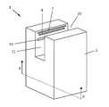
図1は、本発明によるハンドドライヤ1の大幅に簡略化された斜視図を示しており、このハンドドライヤは、ハウジング2を有する。ハウジング2は、上面にハウジングの全幅にわたって延びるハウジング開口20を備える。このハウジング開口に、ハウジング開口20と同様にハウジングの全幅にわたって延びる空洞21が接続される。空洞21は、ハウジング開口20を通じてユーザがその手3を空洞21内に完全に差し込むことができる十分な大きさを有する。これは図3のハンドドライヤの側面図に示されており、同図ではユーザの腕の一部と部分的に空洞21に差し込まれた手3とが図示されている。 FIG. 1 shows a greatly simplified perspective view of a
図2の断面図において明らかなように、ハウジング2の下方の領域には空洞があり、その中には送風機4が配置されていて、これが高速の空気を、2つの通気ダクト70,70’を通じて、2つのフラットノズル7,7’に向けて運ぶ。これらのフラットノズルは、ハウジング開口20に隣接し、空洞21の側部で対向して空洞21に開口している。空気は、フラットノズル7,7’から、少なくとも15m/秒の速度で、空洞21内に差し込まれたユーザの手に向かう方向で吹き付けられる。ファン4は、両センサ8,8’がそれらの間の間隙において物体(通常はユーザの手)を検出すると、動作を開始する。その後、ファン4は所定の期間にわたって動作する。また、UV放射線の生成のための装置5の一部である両ランプ50,50’もオンにされる。装置5は、空洞へ向けて200nm~380nmの波長のUV放射線を放射し、その強度のうち最大で20%が228nm~380nmの波長領域にある。 As can be seen in the cross-sectional view of FIG. 2, the lower area of the
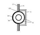
図2aは、UV放射線の生成のための装置5の部分Yを拡大して示す。空洞21の対向する側部におけるランプの配置は、空洞に対応して構成される。ランプ50は、図示される例においては、クリプトンハロゲン化合物エキシマバリア放電ランプ、具体的にはKrCl又はKrBrエキシマバリア放電ランプであって、管形状の電球を有している。この電球は、ハウジング開口20の開口面に平行に延びるとともに、電球とハウジング開口20との間に配置される、センサ8及びフラットノズル7の出口開口に平行に延びるように、配置される。フラットノズルは、本具体例では25cmの長さである。電球51は、空洞21を画定する側壁23において同じく25cmの長さを有するスリット形状の開口230内に、電球によって占められる容積の約3分の1が空洞21の内部に位置し、その一方で電球容積のおよそ3分の2が空洞21の外部に位置するように、配置されている。電球51を部分的に空洞21内に差し込むことで、ランプにより放射された放射線は、ユーザの手のために利用可能な空間が大幅に縮小し、あるいは、ランプが過度に損傷したり汚染したりする危険を被ることなく、空洞21のすべての領域に到達できるようになる。窓構成部材6が、電球51のうち空洞21内に突出している部分を完全に覆い、スリット形状の開口230を空洞21に対して気密且つ湿密に閉塞することで、ランプの保護がさらに図られる。 FIG. 2a shows an enlarged view of part Y of
電球51のうち空洞21内に突出していない領域は、本具体例ではスリット入りの金属スリーブ540の形状を有する反射体54によって囲まれており、スリット開口541は空洞21への放射線放射開口を構成する(図4a及び図4bも参照のこと)。代替的には、反射体54は、金属コーティングであってもよい。金属スリーブ540が用いられる場合には、この金属スリーブは同時に、誘電性のバリア放電ランプの外部電極としても機能し得る。図2の例においては、電球51のうち空洞21内に突出している部分は、空洞に向けて放射される放射線のうち228nmよりも高い領域の波長を有するUV放射線をフィルタ除去することができるフィルタ材料53によって被覆される。代替的又は追加的には、フィルタ材料53は窓構成部材6にも被覆として適用されていてもよく、あるいは、窓構成部材6が全体としてフィルタ材料から製造されてもよい。 The area of the bulb 51 that does not protrude into the
図2bは、フラットノズル7に対して反対側のランプ50’の配置を模式的に示す。同じことは、対応するランプ50及びこれに対して反対側のフラットノズル7’にも当てはまる。図から明らかなように、フラットノズル7は空洞21の内側に向かって若干傾斜している。空気は、少なくとも15m/秒の速度で、エアカーテンとして、矢印及びそれに連なる破線で表された流れ方向Rに沿って、空洞21内に入る。断面では線として表されている流れ方向は、フラットノズル7の全幅にわたって見ると平面を成しており、この平面に基づいて、反対側の側壁23’に向かって楔形に開く角度範囲αが本発明に従って規定される。側壁23’に楔形の領域によって形成される交差断面は、上縁220及び下縁220’を有する、横に延びる帯状の領域22を成す。本発明によれば、この帯の内部にランプ50’が配置される。ここで、角度αは90°であって、流れ方向平面Rの両側に均等に分割され、したがって平面Rの上と下とにそれぞれα/2の45°となる。 FIG. 2b schematically shows the arrangement of the lamps 50' opposite to the
図2,図2a及び図2bからさらに明らかなように、空洞を画定する壁23及び空洞床面は、被覆24を備える。この被覆は光触媒、具体的には二酸化チタンを含む。この光触媒は、UV放射線に曝されたときには、例えば水からのOHラジカル等といったラジカルや、オゾンの発生を引き起こす。これらはそれぞれ殺菌作用を呈する。このようにして、空洞壁への細菌の滞留が阻止される。 As is further apparent from FIGS. 2, 2a and 2b, the
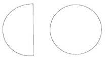
図4a及び図4bは、側壁23及び空洞21に対する電球51の配置に関する2つの異なる可能性を示す。図4aにおいては電球51がほんの僅かにしか空洞21内に突出していないのに対し、図4bにおいては、電球51の容積の約40%が空洞21内にある。電球が空洞21内に突き出せば突き出すほど、空洞はより良好にUV放射線で照射され得るが、損傷及び汚染の危険が高まるとともに、電球及び電球を覆う窓構成部材6のために空洞内により多くの空間を要する。図4aはさらに、ランプ50の別の一例、つまり、LaPO4:Prのような蛍光材料からなる被覆52が、生成された放射線を変換して、228nmを下回る波長を有する放射線の割合を高めたUV放射線を空洞21内に放射するランプを示している。これは例えば、希ガスバリア放電ランプであってもよい。4a and 4b show two different possibilities for the placement of the bulb 51 with respect to the
図5は、本発明によるハンドドライヤ1の代替的な一実施形態を示す。この実施形態は、基本的にランプ50,50’の配置が、図2の実施形態と異なる。ここではランプは完全に空洞21の内部に配置される。開口20に概ね平行に延びる管形状の電球は、空洞21内にユーザの手のために可能な限り多くの空間を残しておくために、可能な限り小さい直径(例えば15mm)を有することが好都合である。 Figure 5 shows an alternative embodiment of the
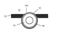
図5a~5cは、ランプ50の配置の様々な可能性を、図5の領域Zについての部分拡大図で示す。図5aにおいては、ランプ50の電球は、空洞21の方向に向かって放射線放射開口541が開口する反射体54によって包囲されている。この放射線放射開口は、30°よりも大きい開口角度θで、本具体例では約80°で、UV放射線が空洞21内に放射されることを可能にする。この開口角度は、ハンドドライヤ1の寸法に応じて、空洞の十分な照射とユーザの手の可及的完全な照射とが行われ得るように選択される。 FIGS. 5a-5c show various possibilities for the placement of the
図5b及び図5cは代替的なランプ配置を示しており、これらの配置では、ランプ50はそれぞれ固定部材25を用いて空洞21の側壁23に固定されている。ここでは、開口角度θは固定部材25の大きさによって定められる。図5bの場合には、固定部材が電球の周囲の約60°のみを覆うので、開口角度は約300°となる。図5cの場合には、固定部材が電球の周囲の約半分を覆い、その結果開口角度は概ね180°となる。 5b and 5c show alternative lamp arrangements, in which the
従来の手の乾燥方法に対する本発明の相対的な有効性に関して調査を行った。本発明の例では、図1及び図2において説明した構造を有するハンドドライヤが用いられ、ランプ50,50’としては、それぞれ222nmの主波長を有するKrClエキシマバリア放電ランプが使用された。これらのランプはそれぞれ約20Wで運転され、手の表面への放射強度は大体3mW/cm2であった。約5秒の乾燥時間における222nmのUV放射線の全線量は、平均で15mJ/cm2であった。乾燥時間の終了後、被験者のそれぞれの手から、3M社の市販のペトリフィルム(登録商標)を用いて試料が採取され、同社の指示書に従って培養された。その後、各ペトリフィルム(登録商標)上に見つかったコロニーが集計された。テスト系列毎に2つの試料が採取された。集計の平均から、テスト系列の検査結果が明らかになった。試験は以下のテスト系列を含んでいた。
1)手は石鹸で徹底的に洗浄され、ハンドドライヤにおいて空洞21内でUV放射線を放射せずに乾燥された。
2)手は石鹸で徹底的に洗浄され、ハンドドライヤにおいて空洞21内でUV放射線を放射して乾燥された。
3)手は洗浄されず、ハンドドライヤにおいて空洞21内でUV放射線を放射せずに乾燥された。
4)手は洗浄されず、ハンドドライヤにおいて空洞21内でUV放射線を放射して乾燥された。A study was conducted regarding the relative effectiveness of the present invention versus conventional hand drying methods. In the example of the present invention, a hand dryer having the structure described in FIGS. 1 and 2 was used, and the
1) Hands were thoroughly washed with soap and dried in
2) Hands were thoroughly washed with soap and dried in a hand dryer with UV radiation in
3) The hands were not washed and dried in the
4) The hands were not washed and dried in the
テスト系列1~4の系列毎に手の表面から採取された2つの試料の写真が図6a~6dに示されており、図の左の領域にはそれぞれペトリフィルム(登録商標)の半分のみが示されている。図6aはテスト系列1の2つの試料の結果を示しており、これらについてはペトリフィルム(登録商標)上のコロニーの集計は24個及び13個、平均で18.5個のコロニーという結果であった。図6bは、2個及び1個のコロニーを含むテスト系列2のペトリフィルム(登録商標)を示し、したがって平均では1.5個のコロニーであった。図6cに示されたペトリフィルム(登録商標)のテスト系列3は、480個及び812個、平均で646個のコロニー、最後に、図6dに図示されたペトリフィルム(登録商標)のテスト系列4は、32個及び43個のコロニー、したがって平均では37.5個のコロニーという結果であった。 Photographs of two samples taken from the surface of the hand for each series of test series 1-4 are shown in FIGS. It is shown. Figure 6a shows the results of two samples of
上記の結果は、基本的には、単に手を乾燥して滅菌を行わなかったテスト系列3と比較して細菌残存率(Restkeimrate)が約3%に相当する、徹底的な手洗い及び乾燥によって、比較的良好な手の浄化が既に可能であることを示している。テスト系列4は、洗浄されていない手の場合でも、単にUV放射線に曝すだけで、手に存在する細菌の著しい減少、すなわちテスト系列3と比較して細菌残存率が約5%~約8%を達成し得ることを明らかにしている。抜群に良い結果、すなわち、テスト系列3と比較して細菌残存率が約0.2%の細菌が略完全に除去された手が、テスト系列2で達成された。つまり、抜群に良い結果は、手の徹底的な洗浄と、本発明のハンドドライヤで本発明に従って選択された波長領域のUV放射線を放射して行う洗浄後の乾燥と、によって、達成された。 The above results are basically based on thorough hand washing and drying, which corresponds to a restkeimrate of about 3% compared to test
Claims (15)
Translated fromJapanese前記UV放射線を生成するための装置(5)は、前記空洞(21)内へ放射される228nm~380nmの領域の波長を有するUV放射線の強度が、前記空洞(21)内へ放射される200nm~380nmの領域の波長を有するUV放射線の強度のうち、最大で20%となるように構成され、
前記ランプ(50)が配置されている空間は、窓構成部材(6)によって前記空洞(21)と仕切られて、前記空洞(21)に対して閉塞されている、ハンドドライヤ。a housing (2) formed internally such that a cavity (21) accessible from the outside through a housing opening (20) accommodates a hand (3) to be dried by air flow within said cavity (21); a device (4) for generating said air flow and at least one lamp (50) emitting radiation in the ultraviolet wavelength range, said at least one lamp (50) emitting UV radiation to said cavity (21). a device (5) for generating UV radiation, arranged in said housing (2) to radiate inwards, said hand dryer (1) comprising:
The device (5) for generating UV radiation is configured so that the intensity of UV radiation having a wavelength in the range of 228 nm to 380 nm emitted into the cavity (21) is 200 nm emitted into the cavity (21) configured to be at most 20% of the intensity of UV radiation having a wavelength in the region of ~380 nm,
A hand dryer, wherein a space in which the lamp (50) is arranged is separated from the cavity (21) by a window component (6), and is closed with respect to the cavity (21).
228nm未満の主放射波長を有するランプ(50)、
蛍光材料(52)を励起する放射線を生成するランプであって、前記蛍光材料の励起によって放射された放射線が228nm未満の主放射波長を有するランプ、又は
228nm~300nmの領域の波長を有するUV放射線をフィルタ除去するフィルタ材料(53)と組み合わせられたランプ(50)から選択されることを特徴とする、請求項1又は請求項2に記載のハンドドライヤ。said at least one lamp (50) comprising:
a lamp (50) having a dominant emission wavelength of less than 228 nm;
A lamp producing radiation to excite a fluorescent material (52), wherein the radiation emitted by excitation of said fluorescent material has a dominant emission wavelength of less than 228 nm, or UV radiation having a wavelength in the range from 228 nm to 300 nm. 3. A hand dryer according to claim 1 or 2, characterized in that it is selected from a lamp (50) combined with a filter material (53) for filtering out the .
Priority Applications (1)
| Application Number | Priority Date | Filing Date | Title |
|---|---|---|---|
| JP2022014832AJP7180804B2 (en) | 2017-10-17 | 2022-02-02 | Lamp and device for generating UV radiation |
Applications Claiming Priority (2)
| Application Number | Priority Date | Filing Date | Title |
|---|---|---|---|
| DE102017009637.6ADE102017009637B4 (en) | 2017-10-17 | 2017-10-17 | Hand dryer with UV disinfection device |
| DE102017009637.6 | 2017-10-17 |
Related Child Applications (1)
| Application Number | Title | Priority Date | Filing Date |
|---|---|---|---|
| JP2022014832ADivisionJP7180804B2 (en) | 2017-10-17 | 2022-02-02 | Lamp and device for generating UV radiation |
Publications (2)
| Publication Number | Publication Date |
|---|---|
| JP2019072490A JP2019072490A (en) | 2019-05-16 |
| JP7194353B2true JP7194353B2 (en) | 2022-12-22 |
Family
ID=63720443
Family Applications (2)
| Application Number | Title | Priority Date | Filing Date |
|---|---|---|---|
| JP2018194912AActiveJP7194353B2 (en) | 2017-10-17 | 2018-10-16 | Hand dryer with UV disinfection device |
| JP2022014832AActiveJP7180804B2 (en) | 2017-10-17 | 2022-02-02 | Lamp and device for generating UV radiation |
Family Applications After (1)
| Application Number | Title | Priority Date | Filing Date |
|---|---|---|---|
| JP2022014832AActiveJP7180804B2 (en) | 2017-10-17 | 2022-02-02 | Lamp and device for generating UV radiation |
Country Status (5)
| Country | Link |
|---|---|
| US (1) | US11116856B2 (en) |
| EP (1) | EP3473150B1 (en) |
| JP (2) | JP7194353B2 (en) |
| CN (1) | CN109662635B (en) |
| DE (1) | DE102017009637B4 (en) |
Families Citing this family (35)
| Publication number | Priority date | Publication date | Assignee | Title |
|---|---|---|---|---|
| DE202017001279U1 (en)* | 2017-03-10 | 2017-08-18 | Harun Özsoy | drying device |
| JP7119534B2 (en) | 2018-04-24 | 2022-08-17 | ウシオ電機株式会社 | Dry sterilization device and dry sterilization method |
| US20230337868A1 (en)* | 2020-03-11 | 2023-10-26 | Quantum Leap Llc | Hand sanitizer |
| US11305025B1 (en)* | 2020-04-28 | 2022-04-19 | Robert Barry | Disinfectant apparatus |
| DE102020111635B4 (en)* | 2020-04-29 | 2022-05-12 | Maier Werkzeugmaschinen GmbH & Co. KG | Device and method for disinfecting a person's hands |
| US11020502B1 (en) | 2020-05-01 | 2021-06-01 | Uv Innovators, Llc | Ultraviolet (UV) light emission device, and related methods of use, particularly suited for decontamination |
| US11986563B1 (en) | 2020-05-07 | 2024-05-21 | James William Potthast | Portable, safe UV hand and surface sanitizer and method of use |
| US11524083B1 (en) | 2020-05-13 | 2022-12-13 | James William Potthast | Personal, portable, hand-held UV sanitizer and method of use |
| US10960094B1 (en)* | 2020-06-16 | 2021-03-30 | Innovative Technologies | Disinfection system |
| US20220001044A1 (en)* | 2020-07-01 | 2022-01-06 | B/E Aerospace, Inc. | Sanitation systems for aircraft |
| JP7706139B2 (en)* | 2020-07-10 | 2025-07-11 | 株式会社イーエムエンジニアリング | UV sterilizer for hands, gate system |
| RU201418U1 (en)* | 2020-07-23 | 2020-12-14 | Андрей Николаевич Руфеев | Sterile air curtain device |
| JP6893054B1 (en)* | 2020-08-07 | 2021-06-23 | 株式会社南一 | Disinfection / sterilization equipment |
| US20220048634A1 (en)* | 2020-08-17 | 2022-02-17 | Goodrich Corporation | Gasper extension for reduced disease transmission |
| JP2023129748A (en) | 2020-08-24 | 2023-09-15 | ルーメンラブズ・エルエルシー | Excimer bulb assembly and excimer bulb cartridge |
| US11752228B2 (en) | 2020-08-24 | 2023-09-12 | Lumenlabs Llc | Highly efficient UV C bulb with multifaceted filter |
| CN116348155A (en)* | 2020-08-24 | 2023-06-27 | 星际光有限责任公司 | 234nm far UVC filter |
| US20220059338A1 (en) | 2020-08-24 | 2022-02-24 | Sportsbeams Lighting, Inc. | Cartridge based uv c sterilization system |
| WO2022051480A1 (en)* | 2020-09-02 | 2022-03-10 | Sloan Valve Company | Ultraviolet hand sanitizer |
| US20220072186A1 (en)* | 2020-09-09 | 2022-03-10 | Aleddra Inc. | Disinfecting Circadian Lighting Device |
| US12281468B2 (en) | 2020-10-13 | 2025-04-22 | Kobler Co. | Sanitization system |
| USD1063102S1 (en) | 2020-10-26 | 2025-02-18 | Lumenlabs Llc | Ultraviolet sanitizing fixture |
| US11638770B2 (en) | 2020-12-09 | 2023-05-02 | Boguslaw Kolakowski | Ultraviolet sanitizing apparatus |
| CN112515518A (en)* | 2020-12-17 | 2021-03-19 | 安徽中科医疗器械有限公司 | High-efficiency mute negative pressure hand dryer |
| WO2022163887A1 (en)* | 2021-02-01 | 2022-08-04 | 신동혁 | Ultrasonic drying device |
| US11313726B1 (en) | 2021-03-23 | 2022-04-26 | Lumenlabs Llc | Safe UV-C dosimeter |
| CN113327839A (en)* | 2021-06-22 | 2021-08-31 | 生命阳光(广州)大健康发展有限公司 | Ultraviolet lamp tube |
| US20220401599A1 (en)* | 2021-06-22 | 2022-12-22 | Langsim Optoelectronic Technologies (Guangdong) Limited | Ultraviolet lamp tube |
| RU208806U1 (en)* | 2021-08-06 | 2022-01-13 | Общество с ограниченной ответственностью "ИНТЕК" | Plasma hand dryer |
| WO2023022738A1 (en)* | 2021-08-16 | 2023-02-23 | Lumenlabs Llc | Efficient uv c sterilization system |
| CN113663095A (en)* | 2021-09-08 | 2021-11-19 | 上海仪电(集团)有限公司中央研究院 | Excimer logistics disinfection system and method thereof |
| DE102021129184A1 (en) | 2021-11-10 | 2023-05-11 | Stiebel Eltron Gmbh & Co. Kg | Ventilation apparatus, in particular air hand dryers |
| US20230145866A1 (en)* | 2021-11-11 | 2023-05-11 | The Boeing Company | Systems and methods for disinfecting hands |
| CN217822656U (en)* | 2022-04-28 | 2022-11-15 | 朗升光电科技(广东)有限公司 | Ultraviolet lamp tube |
| WO2024251346A1 (en)* | 2023-06-05 | 2024-12-12 | Gerg Lighthouse Gmbh | Metal workpiece which can be oxidized, method for thermally generating an oxide layer of the metal workpiece which can be oxidized, and irradiating assembly for irradiating a fluid with ultraviolet radiation |
Citations (3)
| Publication number | Priority date | Publication date | Assignee | Title |
|---|---|---|---|---|
| JP2005305031A (en) | 2004-04-26 | 2005-11-04 | Ishikawajima Harima Heavy Ind Co Ltd | Finger sterilizer |
| JP2006238940A (en) | 2005-02-28 | 2006-09-14 | Central Res Inst Of Electric Power Ind | Restroom utensil |
| JP2016220684A (en) | 2011-03-07 | 2016-12-28 | ザ トラスティーズ オブ コロンビア ユニバーシティ イン ザ シティ オブ ニューヨーク | Bio-composition destruction apparatus, bio-composition destruction apparatus operating method, sterilization apparatus |
Family Cites Families (18)
| Publication number | Priority date | Publication date | Assignee | Title |
|---|---|---|---|---|
| US5216251A (en)* | 1991-10-18 | 1993-06-01 | Matschke Arthur L | Apparatus and method for a bio-conditioning germicidal dryer |
| TW226472B (en)* | 1992-06-01 | 1994-07-11 | Gen Electric | |
| CA2104514C (en)* | 1992-08-25 | 1998-08-25 | Toshio Tatsutani | Hand dryer |
| JPH11214165A (en)* | 1998-01-23 | 1999-08-06 | Kansai Electric Power Co Inc:The | Artificial sunlight device |
| ES2437204T3 (en)* | 2005-01-31 | 2014-01-09 | S. Edward Neister | Procedure and apparatus for sterilizing and disinfecting air and surfaces, and protecting an area against external microbial contamination |
| JP2006351670A (en)* | 2005-06-14 | 2006-12-28 | Ushio Inc | UV irradiation equipment |
| CA2617116C (en) | 2005-07-30 | 2013-02-26 | Dyson Technology Limited | Drying apparatus |
| JP2007291361A (en)* | 2006-03-27 | 2007-11-08 | Toshiba Lighting & Technology Corp | UV cut material, UV cut filter, tube and lighting fixture |
| WO2010015040A1 (en) | 2008-08-07 | 2010-02-11 | Powmri Ltd | Therapy and prevention of tdp-43 proteinopathy |
| KR20110042990A (en)* | 2009-10-20 | 2011-04-27 | 웅진코웨이주식회사 | How to Sterilize the Outlet Trays of Hand Dryers and Hand Dryers |
| DE102012008253A1 (en) | 2012-04-25 | 2013-10-31 | Ushio Europe B.V. | Dryers, especially hand dryers |
| GB2502268B (en)* | 2012-05-21 | 2015-05-13 | Heat Outdoors Ltd | Improved apparatus |
| EP2842870B1 (en)* | 2013-08-30 | 2018-04-18 | Airbus Operations GmbH | Hand treatment device |
| NL2014125B1 (en)* | 2015-01-13 | 2017-01-27 | Hydrowashr B V | Washing device for washing objects, and heater and method therefor. |
| GB201505651D0 (en)* | 2015-04-01 | 2015-05-13 | Stream Hygiene Ltd | Hand treatment apparatus |
| JP6544524B2 (en)* | 2015-05-18 | 2019-07-17 | パナソニックIpマネジメント株式会社 | UV light irradiation device |
| US10455992B2 (en)* | 2016-09-20 | 2019-10-29 | The Boeing Company | Hand dryer having managed air flow |
| US20180214585A1 (en)* | 2017-02-01 | 2018-08-02 | Patrick J. Piper | Disinfection devices and systems |
- 2017
- 2017-10-17DEDE102017009637.6Apatent/DE102017009637B4/ennot_activeExpired - Fee Related
- 2018
- 2018-09-28EPEP18000777.5Apatent/EP3473150B1/enactiveActive
- 2018-10-16JPJP2018194912Apatent/JP7194353B2/enactiveActive
- 2018-10-16USUS16/161,828patent/US11116856B2/enactiveActive
- 2018-10-17CNCN201811209025.7Apatent/CN109662635B/ennot_activeExpired - Fee Related
- 2022
- 2022-02-02JPJP2022014832Apatent/JP7180804B2/enactiveActive
Patent Citations (3)
| Publication number | Priority date | Publication date | Assignee | Title |
|---|---|---|---|---|
| JP2005305031A (en) | 2004-04-26 | 2005-11-04 | Ishikawajima Harima Heavy Ind Co Ltd | Finger sterilizer |
| JP2006238940A (en) | 2005-02-28 | 2006-09-14 | Central Res Inst Of Electric Power Ind | Restroom utensil |
| JP2016220684A (en) | 2011-03-07 | 2016-12-28 | ザ トラスティーズ オブ コロンビア ユニバーシティ イン ザ シティ オブ ニューヨーク | Bio-composition destruction apparatus, bio-composition destruction apparatus operating method, sterilization apparatus |
Also Published As
| Publication number | Publication date |
|---|---|
| JP2019072490A (en) | 2019-05-16 |
| JP7180804B2 (en) | 2022-11-30 |
| JP2022058836A (en) | 2022-04-12 |
| US11116856B2 (en) | 2021-09-14 |
| DE102017009637B4 (en) | 2020-11-26 |
| EP3473150A1 (en) | 2019-04-24 |
| CN109662635B (en) | 2022-07-12 |
| DE102017009637A1 (en) | 2019-05-16 |
| EP3473150B1 (en) | 2022-01-26 |
| CN109662635A (en) | 2019-04-23 |
| US20190117802A1 (en) | 2019-04-25 |
Similar Documents
| Publication | Publication Date | Title |
|---|---|---|
| JP7194353B2 (en) | Hand dryer with UV disinfection device | |
| US12064525B2 (en) | Dry sterilizing device and dry sterilizing method | |
| US7674436B1 (en) | Portable indoor air purification system | |
| KR102138300B1 (en) | air sterilization device and method | |
| JP2013226415A (en) | Dryer, especially hand dryer | |
| JP2009050584A (en) | Deodorant sterilization lighting device | |
| KR101055358B1 (en) | Air sterilizer | |
| KR20110037271A (en) | Air sterilizer | |
| KR102374361B1 (en) | Elevator with disinfection equipment | |
| JP2021177809A (en) | Sterilizer | |
| CN213721677U (en) | Hand drier capable of being used as air sterilizer | |
| KR20060019298A (en) | Hand dryer | |
| KR102350241B1 (en) | Sterilization and drying, deodorization device for mask | |
| KR200384758Y1 (en) | Air Diffuser to protect indoor air from airborne infections by Germicidal ultraviolet lamp and Photocatalyst coated honeycomb plate | |
| JP2013081726A (en) | Finger drier | |
| JP3235419U (en) | Blower with sterilization function | |
| CN212720012U (en) | Air conditioner indoor unit and air conditioner | |
| JP2006068187A (en) | Hair dryer | |
| KR200173987Y1 (en) | Ultraviolet rays sterilizer have reflector | |
| KR200419944Y1 (en) | Hair dryer with ultraviolet rays | |
| KR20210117083A (en) | Multi sterilizer having air sterilization function | |
| JP3236755U (en) | Spatial sterilizer | |
| JP2016016114A (en) | bathroom | |
| KR102597225B1 (en) | Gate System with Plasma Shower | |
| CN120292645B (en) | Air purification device |
Legal Events
| Date | Code | Title | Description |
|---|---|---|---|
| A621 | Written request for application examination | Free format text:JAPANESE INTERMEDIATE CODE: A621 Effective date:20210309 | |
| A711 | Notification of change in applicant | Free format text:JAPANESE INTERMEDIATE CODE: A711 Effective date:20220118 | |
| A521 | Request for written amendment filed | Free format text:JAPANESE INTERMEDIATE CODE: A821 Effective date:20220118 | |
| A131 | Notification of reasons for refusal | Free format text:JAPANESE INTERMEDIATE CODE: A131 Effective date:20220301 | |
| A521 | Request for written amendment filed | Free format text:JAPANESE INTERMEDIATE CODE: A523 Effective date:20220428 | |
| A131 | Notification of reasons for refusal | Free format text:JAPANESE INTERMEDIATE CODE: A131 Effective date:20220715 | |
| A521 | Request for written amendment filed | Free format text:JAPANESE INTERMEDIATE CODE: A523 Effective date:20220829 | |
| TRDD | Decision of grant or rejection written | ||
| A01 | Written decision to grant a patent or to grant a registration (utility model) | Free format text:JAPANESE INTERMEDIATE CODE: A01 Effective date:20221111 | |
| A61 | First payment of annual fees (during grant procedure) | Free format text:JAPANESE INTERMEDIATE CODE: A61 Effective date:20221124 | |
| R151 | Written notification of patent or utility model registration | Ref document number:7194353 Country of ref document:JP Free format text:JAPANESE INTERMEDIATE CODE: R151 |