JP7190932B2 - Sunshade device, automobile equipped with the sunshade device, and method for manufacturing the sunshade device - Google Patents
Sunshade device, automobile equipped with the sunshade device, and method for manufacturing the sunshade deviceDownload PDFInfo
- Publication number
- JP7190932B2 JP7190932B2JP2019025110AJP2019025110AJP7190932B2JP 7190932 B2JP7190932 B2JP 7190932B2JP 2019025110 AJP2019025110 AJP 2019025110AJP 2019025110 AJP2019025110 AJP 2019025110AJP 7190932 B2JP7190932 B2JP 7190932B2
- Authority
- JP
- Japan
- Prior art keywords
- shade
- base material
- pieces
- main body
- sunshade device
- Prior art date
- Legal status (The legal status is an assumption and is not a legal conclusion. Google has not performed a legal analysis and makes no representation as to the accuracy of the status listed.)
- Active
Links
- 238000004519manufacturing processMethods0.000titleclaimsdescription29
- 238000000034methodMethods0.000titleclaimsdescription17
- 239000000463materialSubstances0.000claimsdescription200
- 229920005989resinPolymers0.000claimsdescription92
- 239000011347resinSubstances0.000claimsdescription92
- 230000003014reinforcing effectEffects0.000claimsdescription57
- 238000007493shaping processMethods0.000claimsdescription44
- 239000003365glass fiberSubstances0.000claimsdescription39
- 238000000465mouldingMethods0.000claimsdescription30
- 239000000758substrateSubstances0.000claimsdescription26
- 230000002093peripheral effectEffects0.000claimsdescription24
- 238000003825pressingMethods0.000claimsdescription21
- JOYRKODLDBILNP-UHFFFAOYSA-NEthyl urethaneChemical compoundCCOC(N)=OJOYRKODLDBILNP-UHFFFAOYSA-N0.000claimsdescription9
- 229920001187thermosetting polymerPolymers0.000claimsdescription5
- 229920005992thermoplastic resinPolymers0.000claimsdescription4
- 102100040428Chitobiosyldiphosphodolichol beta-mannosyltransferaseHuman genes0.000claims1
- 238000001746injection mouldingMethods0.000description18
- 239000002313adhesive filmSubstances0.000description12
- 230000000694effectsEffects0.000description6
- 238000010030laminatingMethods0.000description5
- 230000015572biosynthetic processEffects0.000description4
- 230000001965increasing effectEffects0.000description4
- 238000002347injectionMethods0.000description4
- 239000007924injectionSubstances0.000description4
- 239000000470constituentSubstances0.000description3
- 239000006260foamSubstances0.000description3
- 230000008569processEffects0.000description3
- 239000000853adhesiveSubstances0.000description2
- 230000001070adhesive effectEffects0.000description2
- 239000003054catalystSubstances0.000description2
- 239000004745nonwoven fabricSubstances0.000description2
- 238000003466weldingMethods0.000description2
- 229910052782aluminiumInorganic materials0.000description1
- XAGFODPZIPBFFR-UHFFFAOYSA-NaluminiumChemical compound[Al]XAGFODPZIPBFFR-UHFFFAOYSA-N0.000description1
- 230000008859changeEffects0.000description1
- 238000005520cutting processMethods0.000description1
- 238000010586diagramMethods0.000description1
- 230000003028elevating effectEffects0.000description1
- 239000004744fabricSubstances0.000description1
- 239000000835fiberSubstances0.000description1
- 239000006261foam materialSubstances0.000description1
- 238000005187foamingMethods0.000description1
- 239000010985leatherSubstances0.000description1
- 239000007769metal materialSubstances0.000description1
- 238000012986modificationMethods0.000description1
- 230000004048modificationEffects0.000description1
- 230000002787reinforcementEffects0.000description1
- 239000013585weight reducing agentSubstances0.000description1
Images


Landscapes
- Vehicle Interior And Exterior Ornaments, Soundproofing, And Insulation (AREA)
- Casting Or Compression Moulding Of Plastics Or The Like (AREA)
Description
Translated fromJapanese本発明は、サンシェード装置、当該サンシェード装置を備える自動車及びサンシェード装置の製造方法に関する。 The present invention relates to a sunshade device, an automobile equipped with the sunshade device, and a method for manufacturing the sunshade device.
従来、この種のサンシェード装置においては、下記特許文献1に記載のサンシェード装置が提案されている。当該サンシェード装置はシェードプレートを備えており、このシェードプレートは、サンシェード装置における日よけとしての主体的役割を果たす。 Conventionally, in this type of sunshade device, a sunshade device described in Patent Document 1 below has been proposed. The sunshade device comprises a shade plate, which plays the main role as a shade in the sunshade device.
また、サンシェード装置は、ノブ及び4つの摺動部材を備えている。ノブは、室外側部材及び室内側部材でもって構成されており、これら室外側部材及び室内側部材は、シェードプレートの前側左右方向中央部に形成した取り付け孔部にその両側から取り付けられている。 The sunshade device also has a knob and four sliding members. The knob is composed of an outdoor side member and an indoor side member, and these outdoor side member and indoor side member are attached from both sides to mounting holes formed in the center portion of the shade plate in the front lateral direction.
この組み付けは、室内側部材の指掛け部をシェードプレートの取り付け孔部を通して室外側部材の受け部内に嵌装するとともに、室内側部材の左右両側係止突起をシェードプレートの取り付け孔部の左右両側部位を介し室外側部材の左右両側係止孔部に係止することによりなされている。 In this assembly, the finger hooks of the indoor member are fitted into the receiving portions of the outdoor member through the mounting holes of the shade plate, and the locking projections on both left and right sides of the indoor member are positioned on both left and right sides of the mounting holes of the shade plate. are engaged with the right and left locking holes of the outdoor member via the .
また、4つの摺動部材は、それぞれ、シェードプレートの左右両側端部にその各前後部位にて取り付けられている。 Also, the four sliding members are attached to the left and right side ends of the shade plate at their front and rear portions, respectively.
以上によれば、サンシェード装置が、その各摺動部材にて、自動車の屋根に案内レールを介し前後方向に摺動可能に支持されたとき、ノブを指賭け部に指を掛けて前後方向に移動させることで、各摺動部材によりサンシェード装置を案内レールに沿い前後方向に摺動させる。 According to the above, when the sunshade device is slidably supported in the front-rear direction on the roof of the automobile via the guide rails by the sliding members, the knob can be moved in the front-rear direction by hooking the finger on the finger rest portion. By moving, the sunshade device is slid forward and backward along the guide rail by each sliding member.
また、当該サンシェード装置は、通常、帯状補強板を備えており、当該帯状補強板は、シェードプレートの後部に沿いリベット等でもって固着されている。これにより、当該帯状補強版は、シェードプレートをその後部側から補強する役割を果たす。 Further, the sunshade device generally includes a band-shaped reinforcing plate, and the band-shaped reinforcing plate is fixed with rivets or the like along the rear portion of the shade plate. Thus, the belt-shaped reinforcing plate serves to reinforce the shade plate from the rear side.
ところで、上述したサンシェード装置においては、取っ手、各摺動部材や帯状補強板は、共に、シェードプレートとは別部品となっている。従って、サンシェード装置を完成させるにあたっては、取っ手、各摺動部材或いは帯状補強板を、シェードプレートに別途組付けなければならず、このような組み付け作業は、余分な作業であるのは勿論のこと、サンシェード装置の完成に際して作業効率の低下を招く。 By the way, in the sunshade device described above, the handle, each sliding member, and the belt-like reinforcing plate are all separate parts from the shade plate. Therefore, in order to complete the sunshade device, the handle, each sliding member, or the belt-shaped reinforcing plate must be separately assembled to the shade plate, and such assembly work is of course an extra work. , the work efficiency is lowered when the sunshade device is completed.
例えば、取っ手を例に挙げると、当該取っ手は、上述したごとく、室外側部材と室内側部材という別体の2部品によって構成されている。このため、これら2部品を製造するにはそれぞれ別々の金型が必要になって、製造コストの増大を招く。また、取っ手をシェードプレートに組み付ける作業は、余分な作業であるのは勿論のこと、サンシェード装置としての製造工程数が増加してしまう。また、上述のような組み付け作業にあたっては、作業台も必要となり、製造コストが増大する。 For example, taking a handle as an example, as described above, the handle is composed of two separate parts, an outdoor-side member and an indoor-side member. For this reason, separate molds are required to manufacture these two parts, resulting in increased manufacturing costs. Moreover, the work of assembling the handle to the shade plate is not only an extra work, but also increases the number of manufacturing steps for the sunshade device. In addition, a workbench is also required for the assembly work as described above, which increases the manufacturing cost.
そこで、本発明は、以上のようなことに対処するため、シェードを賦形するときに、取っ手部材、摺動部材及び補強板部の少なくとも1つをシェードと一体的に形成するようにしたサンシェード装置、当該サンシェード装置を備える自動車及びサンシェード装置の製造方法を提供することを目的とする。 Therefore, in order to deal with the above problems, the present invention provides a sunshade in which at least one of a handle member, a sliding member and a reinforcing plate portion is integrally formed with the shade when shaping the shade. An object of the present invention is to provide a device, a vehicle equipped with the sunshade device, and a method for manufacturing the sunshade device.
上記課題の解決にあたり、本発明に係るサンシェード装置は、請求項1の記載によれば、一方向或いはその逆方向に移動可能に構成される。 In order to solve the above problems, according to claim 1, a sunshade device according to the present invention is configured to be movable in one direction or in the opposite direction.
当該サンシェード装置において、
基材(80)を所定の形状に賦形してなるシェード(30)と、
基材の上記一方向側の端部の中央部位に形成してなるスリット部(80g)内に介装されるU字状窪み部(41)及び当該U字状窪み部の開口部から基材の一側面に沿い環状に延出する鍔部(42)を有する指掛け部(40a)と、上記U字状窪み部の外周部から基材の他側面に沿い環状に延出するフランジ部(40b)とを備え、基材のシェードとしての上記賦形の際に、上記指掛け部及び上記フランジ部を樹脂による一体成形でもってシェードに形成してなる取っ手部材(40)とを備えることを特徴とする。In the sunshade device,
a shade (30) formed by shaping a base material (80) into a predetermined shape;
A U-shaped depression (41) interposed in a slit (80g) formed in the central portion of the one-way end of the base material, and the substrate from the opening of the U-shaped depression A finger hook portion (40a) having a collar portion (42) extending annularly along one side surface, and a flange portion (40b) extending annularly along the other side surface of the substrate from the outer peripheral portion of the U-shaped recessed portion. ), and a handle member (40) formed by integrally molding the finger hook portion and the flange portion with a resin when shaping the base material as a shade. do.
このような構成によれば、取っ手部材が、基材のシェードとしての賦形の際に、指掛け部及びフランジ部を樹脂による一体成形でもってシェードに形成されている。従って、取っ手部材のシェードに対する組み付け作業が不要となる。また、指掛け部及びフランジ部用の各金型装置が不要となるので、製造コストの軽減につながる。 According to such a configuration, the handle member is formed in the shade by integrally molding the finger hook portion and the flange portion with a resin when shaping the base material into the shade. Therefore, it is not necessary to assemble the handle member to the shade. Moreover, since mold devices for the finger hook portion and the flange portion are not required, the manufacturing cost can be reduced.
また、本発明に係るサンシェード装置は、請求項2の記載によれば、一方向或いはその逆方向に移動可能に構成される。 Also, according to the description of claim 2, the sunshade device according to the present invention is configured to be movable in one direction or in the opposite direction.
当該サンシェード装置において、
矩形状の基材本体、当該基材本体の前記一方向側の端部の前記一方向に対する直角方向両側端部から互いに逆向きに外方へ延出されて前記一方向に沿い両開口部を形成してなる一方向側両基材片、及び前記基材本体の前記逆方向側の端部の前記逆方向に対する直角方向両側端部から互いに逆向きに外方へ延出されて前記一方向に沿い両開口部を形成してなる逆方向側両基材片からなる基材のうちの前記矩形状の基材本体を所定の形状に賦形してなるシェード本体と、前記一方向側両基材片からなる一方向側両シェード片と、前記逆方向側両基材片からなる逆方向側両シェード片とを備えるシェードと、
前記基材本体の前記一方向側の端部の中央部位に形成してなるスリット部内に介装されるU字状窪み部及び当該U字状窪み部の開口部から前記基材本体の一側面に沿い環状に延出する鍔部を有する指掛け部と、前記U字状窪み部の外周部から前記基材本体の他側面に沿い環状に延出するフランジ部とを備え、前記基材本体の前記シェード本体としての前記賦形の際に、前記指掛け部及び前記フランジ部を前記基材本体に対し樹脂による一体成形でもって形成してなる取っ手部材と、
前記基材本体の前記シェード本体としての前記賦形の際に、前記一方向側両シェード片に樹脂による一体成形でもって形成してなる一方向側両摺動部材と、
前記基材本体の前記シェード本体としての前記賦形の際に、前記逆方向側両シェード片に樹脂による一体成形でもって形成してなる逆方向側両摺動部材とを備えており、
前記一方向側両摺動部材の各々は、前記一方向側両シェード片のうちの対応一方向側シェード片の前記両開口部を埋めるとともに当該対応一方向側シェード片を覆うように形成してなる摺動部材本体と、当該摺動部材本体にその両面側から隆起する両側押圧部とを一体的に有するように構成されており、
前記逆方向側両摺動部材の各々は、前記逆方向側両シェード片のうちの対応逆方向側シェード片の前記両開口部を埋めるとともに当該対応逆方向側シェード片を覆うように形成してなる摺動部材本体と、当該摺動部材本体にその両面側から隆起する両側押圧部とを一体的に有するように構成されていることを特徴とする。In the sunshade device,
a rectangular base body, extending outward in opposite directions from both ends of the base body on the one direction side in a direction perpendicular to the one direction to form both openings along the one direction; Both base material pieces formed on one side and the opposite side end of the base material main body are extended outward in opposite directions to each other from both side ends in the direction perpendicular to the opposite direction. a shade body formed by shaping the rectangular base body of the base material consisting of opposite direction side base material pieces formed with both openings along the two sides into a predetermined shape, and the one direction side both sides a shade comprising both one-direction-side shade pieces made of base material pieces and both opposite-direction-side shade pieces made of both the opposite-direction-side base material pieces;
A U-shaped recess interposed in a slit formed in a central portion of the one-direction end of the base body, and one side surface of the base body from the opening of the U-shaped recess and a flange portion annularly extending from the outer peripheral portion of the U-shaped recess along the other side surface of the substrate body, a handle member formed by integrally molding the finger hook portion and the flange portion with the base body by resin molding during the shaping as the shade body;
both sliding members on one direction side formed by integral molding of resin on both shade pieces on one direction side when shaping the base body as the shade body;
opposite direction side sliding members formed by integral molding of the opposite direction side shade pieces with a resin when shaping the base material main body as the shade main body,
Each of the one-way-side sliding members is formed so as to fill the openings of the corresponding one-way-side shade piece of the one-way-side shade pieces and to cover the corresponding one-way-side shade piece. The sliding member main body and both side pressing portions protruding from both sides of the sliding member main body are integrally provided,
Each of the opposite direction side sliding members is formed so as to fill the openings of the corresponding opposite direction side shade piece of the opposite direction side shade pieces and to cover the corresponding opposite direction side shade piece. The sliding member main body and both side pressing portions protruding from both sides of the sliding member main body are integrally provided.
これによれば、基材を基材本体、一方向側両基材片及び逆方向側両基材片でもって構成するとともに、シェードをシェード本体、一方向側両シェード片及び逆方向側シェード片でもって構成し、基材本体のシェード本体としての賦形の際に、基材本体のスリット部を介し取っ手部材を請求項1の場合と同様に形成するだけでなく、一方向側両基材片に対応する一方向側両シェード片に一方向側両摺動部材を樹脂による一体成形でもって形成するとともに逆方向側両シェード片に逆方向側両摺動部材を樹脂による一体成形でもって形成するようにした。 According to this, the base material is composed of the base material body, both one-direction side base material pieces, and both opposite-direction side base material pieces, and the shade is composed of the shade main body, both one-direction side shade pieces, and the opposite-direction side shade pieces. When shaping the base material as a shade main body, not only the handle member is formed through the slit portion of the base material body in the same manner as in claim 1, but also both base materials on one direction side. Both unidirectional sliding members are integrally molded with resin on both unidirectional shade pieces corresponding to the shade pieces, and both opposite directional sliding members are integrally molded with resin on both opposite directional shade pieces. I made it
これに伴い、サンシェード装置が、シェードに取っ手部材だけでなく、一方向側両摺動部材及び逆方向側両摺動部材をも、樹脂による一体成形のもとに備える装置として形成され得る。その結果、取っ手部材だけでなく一方向側両摺動部材及び逆方向側両摺動部材のシェードに組み付ける作業が全く不要となる。 Along with this, the sunshade device can be formed as a device having not only a handle member but also both one-way side sliding members and both opposite direction side sliding members integrally molded with resin in the shade. As a result, it is completely unnecessary to assemble not only the handle member but also the one-way sliding members and the opposite-direction sliding members to the shade.
また、本発明は、請求項3の記載によれば、請求項2に記載のサンシェード装置において、
基材本体の前記シェード本体としての前記賦形の際に、前記基材本体の前記逆方向側の端部に沿いその裏面側から樹脂による一体成形でもって形成してなる補強板部を備えることを特徴とする。Further, according to the description of claim 3, the present invention provides the sunshade device according to claim 2,
A reinforcing plate portion formed by integral molding of a resin from the back side along the opposite-side end of the base material body when shaping the base material body as the shade body is provided. characterized by
これにより、補強板部をも、基材本体の前記シェード本体としての前記賦形の際に、シェード本体の逆方向端部に樹脂による一体成形でもって形成するので、補強板部のシェードに対する組み付け作業が全く不要となる。 As a result, the reinforcing plate portion is also integrally molded with resin at the opposite end portion of the shade main body when the base material body is shaped as the shade main body, so that the reinforcing plate portion can be assembled to the shade. No work is required.
また、本発明は、請求項4の記載によれば、請求項1~3のいずれか1つに記載のサンシェード装置において、
基材は、熱硬化性樹脂または熱可塑性樹脂からなる発泡ウレタン材料により形成される板状の主材(70)と、当該主材にその表面側から積層されるガラス繊維マット(71)と、当該ガラス繊維マットにその表面側から積層される表皮(73)と、当該主材にその裏面側から積層されるガラス繊維マット(64)と、当該ガラス繊維マットにその裏面側から積層される裏皮(75)とからなることを特徴とする。Further, according to the description of claim 4, the present invention provides the sunshade device according to any one of claims 1 to 3,
The base material includes a plate-like main member (70) formed of a foamed urethane material made of thermosetting resin or thermoplastic resin, a glass fiber mat (71) laminated on the main member from the surface side, A skin (73) laminated on the glass fiber mat from the front side, a glass fiber mat (64) laminated on the main material from the back side, and a back laminated on the glass fiber mat from the back side. and a skin (75).
このような構成によれば、基材は、主として、発泡ウレタン材料からなる板状の主材を、その両側からガラス繊維マットでサンドイッチ状態にしたものによって形成される。このため、サンシェード装置を軽量化することができる。 According to such a configuration, the substrate is formed by sandwiching a plate-shaped main member made of urethane foam material with glass fiber mats on both sides thereof. Therefore, the weight of the sunshade device can be reduced.
また、本発明に係る自動車は、請求項5の記載によれば、
窓(W)を形成してなるサンルーフ(20)を有する車体(10)と、
請求項2或いは3に記載のサンシェード装置(SD、SD1)と、
当該サンシェード装置をその前記各摺動部材を介し前記窓に対し摺動可能に支持する案内レール装置を備える。In addition, according to the description of
a vehicle body (10) having a sunroof (20) formed with windows (W);
A sunshade device (SD, SD1) according to claim 2 or 3;
A guide rail device is provided for slidably supporting the sunshade device with respect to the window via each of the sliding members.
このような構成によれば、請求項2或いは3に記載の発明の作用効果を達成し得るサンシェード装置を備えた自動車の提供が可能となる。 According to such a configuration, it is possible to provide an automobile equipped with a sunshade device capable of achieving the effects of the invention described in claim 2 or 3.
また、本発明に係るサンシェードの製造方法は、請求項6の記載によれば、一方向或いはその逆方向に移動可能に構成されるサンシェード装置の製造方法である。 According to claim 6, a method for manufacturing a sunshade according to the present invention is a method for manufacturing a sunshade device configured to be movable in one direction or in the opposite direction.
当該製造方法において、
基材を、その前記一方向側の端部の中央部位に形成してなるスリット部を有する基材として準備し、
前記基材をシェードとして賦形するとともに、当該賦形の際に前記基材の前記スリット部を押し広げる第1工程と、
前記第1工程にて賦形された前記基材の前記押し広げられたスリット部内に介装されるU字状窪み部及び当該U字状窪み部の開口部から前記基材の一側面に沿い環状に延出する鍔部を有する指掛け部と、前記U字状窪み部の外周部から前記基材の他側面に沿い環状に延出するフランジ部とを備える取っ手部材の前記フランジ部及び前記指掛け部に対応して前記基材の裏面から前記押し広げられたスリット部を介し前記基材の表面にかけて形成されるキャビティ内に、前記基材の前記シェードとしての前記賦形の際に、溶融樹脂を充填することで、前記取っ手部材を前記シェードに一体的に形成する第2工程とを備えることを特徴とする。In the manufacturing method,
preparing a base material as a base material having a slit portion formed at a central portion of the end portion on the one-way side;
A first step of shaping the base material as a shade and expanding the slit portion of the base material during the shaping;
Along one side of the substrate from the opening of the U-shaped recess interposed in the expanded slit portion of the base material shaped in the first step and the opening of the U-shaped recess said flange portion and said finger hook of a handle member comprising: a finger hook portion having an annularly extending flange; and a flange portion annularly extending along the other side surface of said base material from an outer peripheral portion of said U-shaped recess In the cavity formed from the back surface of the base material to the surface of the base material through the widened slit part corresponding to the part, during the shaping of the base material as the shade, molten resin and a second step of integrally forming the handle member with the shade by filling with.
このような構成によれば、請求項1に記載の発明と同様の作用効果を達成し得るサンシェード装置の提供が可能となる。 With such a configuration, it is possible to provide a sunshade device capable of achieving the same effect as the first aspect of the invention.
また、本発明に係るサンシェード装置の製造方法は、請求項7の記載によれば、一方向或いはその逆方向に移動可能に構成されるサンシェード装置の製造方法である。 Also, according to the seventh aspect of the present invention, there is provided a method for manufacturing a sunshade device which is configured to be movable in one direction or in the opposite direction.
当該製造方法において、
基材を、その前記一方向側の端部の中央部位に形成してなるスリット部を有する基材本体と、当該基材本体の前記一方向側の端部の前記一方向に対する直角方向両側端部から互いに逆向きに外方へ延出されて前記一方向に沿い両開口部を形成してなる一方向側両基材片、及び前記基材本体の前記逆方向側の端部の前記逆方向に対する直角方向両側端部から互いに逆向きに外方へ延出されて前記一方向に沿い両開口部を形成してなる逆方向側両基材片からなる基材として準備し、
前記基材本体をシェード本体として賦形するとともに当該シェード本体と共にシェードを構成するように前記一方向側両基材片及び前記逆方向側両基材片を一方向側両シェード片及び逆方向側両シェード片とし、当該賦形の際に前記基材本体の前記スリット部を押し広げる第1工程と、
前記第1工程にて賦形された前記基材本体の前記押し広げられたスリット部内に介装されるU字状窪み部及び当該U字状窪み部の開口部から前記基材本体の一側面に沿い環状に延出する鍔部を有する指掛け部と、前記U字状窪み部の外周部から前記基材本体の他側面に沿い環状に延出するフランジ部とを備える取っ手部材の前記フランジ部及び前記指掛け部に対応して前記基材本体の裏面から前記押し広げられたスリット部を介し前記基材本体の表面にかけて形成される第1キャビティ部内に、前記基材本体の前記シェード本体としての前記賦形の際に、溶融樹脂を充填することで、前記取っ手部材を前記シェード本体の前記一方向側の端部の中央部位に一体的に形成する第2工程と、
一方向側両摺動部材及び逆方向側摺動部材に対応して前記一方向側両シェード片及び前記逆方向側両シェード片を覆うように形成される第2及び第3のキャビティ部内に、前記基材本体の前記シェード本体としての前記賦形の際に、溶融樹脂を充填することで、前記一方向側両摺動部材及び前記逆方向側摺動部材を前記一方向側両シェード片及び前記逆方向側両シェード片に形成する第3工程とを備えることを特徴とする。In the manufacturing method,
A substrate main body having a slit portion formed by forming a substrate at a central portion of the end portion on the one-direction side thereof; one-direction-side base material pieces extending outward in opposite directions from each other to form both openings along the one direction; Prepared as a base material consisting of both opposite direction side base material pieces extending outward in mutually opposite directions from both ends in a direction perpendicular to the direction to form both openings along the one direction,
The base material pieces on the one direction side and the base material pieces on the opposite direction side are combined with the shade pieces on the one direction side and the opposite direction side so that the base material body is shaped as a shade body and a shade is formed together with the shade body. a first step of forming both shade pieces and expanding the slit portion of the base body during the shaping;
A U-shaped recess interposed in the widened slit portion of the base body formed in the first step, and one side surface of the base body from the opening of the U-shaped recess The flange portion of the handle member comprising: a finger hook portion having a flange portion extending annularly along the edge; and a flange portion annularly extending from the outer peripheral portion of the U-shaped recess along the other side surface of the base body. and in a first cavity portion formed from the back surface of the base material body to the front surface of the base material body through the widened slit portion corresponding to the finger hook portion, the shade body of the base material body is provided in the first cavity portion. a second step of integrally forming the handle member at the central portion of the one-direction-side end portion of the shade main body by filling molten resin during the shaping;
In second and third cavities formed to cover the one-direction side shade pieces and the opposite direction side shade pieces corresponding to the one-direction side sliding members and the opposite direction side sliding members, When the base material body is shaped as the shade body, the one-direction side sliding members and the opposite direction side sliding members are replaced with the one-direction side shade pieces and the opposite direction side sliding members by filling molten resin. and a third step of forming on both the opposite direction side shade pieces.
これによれば、請求項2に記載の発明と同様の作用効果を達成し得るサンシェード装置の提供が可能となる。 According to this, it is possible to provide a sunshade device capable of achieving the same effect as the invention described in claim 2.
また、本発明は、請求項8の記載によれば、請求項7に記載のサンシェード装置の製造方法において、
基材本体の前記逆方向側の端部に沿いその裏面側から形成される補強板部に対応して前記基材本体の前記逆方向側の端部に沿い形成される第4キャビティ部内に、前記基材本体の前記シェード本体としての前記賦形の際に、溶融樹脂を充填することで、前記補強板部を前記シェード本体の前記逆方向側の端部に沿い前記補強板部を一体的に形成する第4工程を備えることを特徴とする。Further, according to the description of claim 8, the present invention provides a method for manufacturing a sunshade device according to claim 7,
In a fourth cavity portion formed along the opposite end of the base body corresponding to the reinforcing plate portion formed from the back side along the opposite end of the base body, When the base material body is shaped as the shade body, the reinforcing plate part is integrally formed along the opposite direction side end of the shade body by filling the molten resin. It is characterized by comprising a fourth step of forming the
これによれば、請求項3に記載の発明と同様の作用効果を達成し得るサンシェード装置の提供が可能となる。 According to this, it is possible to provide a sunshade device capable of achieving the same effect as the invention described in claim 3.
また、本発明は、請求項9の記載によれば、請求項6~8のいずれか1つに記載のサンシェード装置の製造方法において、
基材は、熱硬化性樹脂または熱可塑性樹脂からなる発泡ウレタン材料により形成される板状の主材(70)と、当該主材にその表面側から積層されるガラス繊維マット(71)と、当該ガラス繊維マットにその表面側から積層される表皮(73)と、当該主材にその裏面側から積層されるガラス繊維マット(74)と、当該ガラス繊維マットにその裏面側から積層される裏皮(75)とからなり、
基材を形成するにあたっては、主材に、その表面側からガラス繊維マット及び表皮を順に積層し、その裏面側からガラス繊維マット及び裏皮を積層することにより、基材を形成することを特徴とする。Further, according to the description of claim 9, the present invention provides a method for manufacturing a sunshade device according to any one of claims 6 to 8,
The base material includes a plate-like main member (70) formed of a foamed urethane material made of thermosetting resin or thermoplastic resin, a glass fiber mat (71) laminated on the main member from the surface side, A skin (73) laminated on the glass fiber mat from the front side, a glass fiber mat (74) laminated on the main material from the back side, and a back laminated on the glass fiber mat from the back side. a skin (75);
In forming the base material, the base material is formed by sequentially laminating the glass fiber mat and the skin from the front side of the main material, and laminating the glass fiber mat and the back skin from the back side of the main material. and
このような構成によれば、請求項6~8のいずれか1つに記載の発明と同様の作用効果を達成し得る。 With such a configuration, the same effect as the invention described in any one of claims 6 to 8 can be achieved.
なお、上記各手段の括弧内の符号は、後述する各実施形態に記載の具体的手段との対応関係を示す。 It should be noted that the symbols in parentheses of the above means indicate correspondence with specific means described in each embodiment to be described later.
以下、本発明の各実施形態を図面により説明する。 Hereinafter, each embodiment of the present invention will be described with reference to the drawings.
(第1実施形態)
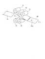
図1は、自動車に適用された本発明に係るサンシェードの第1実施形態を示している。当該自動車は、車体10を備えており、この車体10の屋根20には、窓Wが設けられている。なお、屋根20は、窓Wを有する当該自動車のサンルーフとしての役割を果たすもので、当該屋根20は、図2にて示すごとく、外板21及び内板22でもって構成されている。(First embodiment)
FIG. 1 shows a first embodiment of a sunshade according to the invention applied to an automobile. The automobile includes a
窓Wは、図1或いは図2にて示すごとく、透明パネルW1と、窓用開口部W2とでもって構成されており、透明パネルW1は、屋根20の外板21に形成した嵌め込み用開口部21a(図2参照)に嵌め込まれている。 The window W, as shown in FIG. 1 or 2, comprises a transparent panel W1 and a window opening W2. 21a (see FIG. 2).
窓用開口部W2は、図2にて示すごとく、透明パネルW1に下方から対向するように屋根20の内板22に形成されている。詳細には、当該窓用開口部W2は、図2にて示すごとく、車体10の車室11内における前側座席(図示しない)にその上方から対向するように、屋根20の内板22に開口形成されている。 As shown in FIG. 2, the window opening W2 is formed in the
本第1実施形態では、各符号M1、M2は、それぞれ、上記前後両側座席に着座した各乗員を示す(図2参照)。なお、図1及び図2において、図示右側及び左側が、それぞれ、車体20の前側及び後側に対応する。 In the first embodiment, the symbols M1 and M2 respectively indicate the occupants seated on the front and rear seats (see FIG. 2). 1 and 2, the right side and left side of the drawing correspond to the front side and the rear side of the
本第1実施形態にいうサンシェード装置(以下、サンシェード装置SDという)は、案内レール装置GR(図4参照)を介し、窓Wの窓用開口部W2に対し前後方向に移動可能に支持されるようになっている。本第1実施形態において、案内レール装置GRは、屋根20の外板21と内板22との間にて窓用開口部W2に組み付けられており、当該案内レール装置GRは、図4にて示すごとく、左右両側レールGRaと、前後両側帯状支持板GRbでもって構成されている。左右両側レールGRaは、それぞれ、金属材料、例えば、アルミニウムにより、上側レール壁GR1、下側レール壁GR2及び底側レール壁GR3でもって、形成されている。 The sunshade device (hereinafter referred to as sunshade device SD) according to the first embodiment is movably supported in the front-rear direction with respect to the window opening W2 of the window W via the guide rail device GR (see FIG. 4). It's like In the first embodiment, the guide rail device GR is attached to the window opening W2 between the
本第1実施形態では、上側レール壁GR1、下側レール壁GR2及び底側レール壁GR3は、共に、平板状壁であることから、左右両側レールGRaの各々は、直線状レールとなっている。 In the first embodiment, since the upper rail wall GR1, the lower rail wall GR2, and the bottom rail wall GR3 are all flat walls, each of the left and right rails GRa is a linear rail. .
ここで、左側レールGRaでは、上側レール壁GR1及び下側レール壁GR2が、底側レール壁GR3の上下両側縁部から右方へ互いに平行に延出している。これにより、左側レールGRaは、上側レール壁GR1、下側レール壁GR2及び底側レール壁GR3でもって、横断面横U字状に形成されており、当該左側レールGRa内には、溝部GR4が、右方へ開口するように形成されている。 Here, in the left rail GRa, the upper rail wall GR1 and the lower rail wall GR2 extend to the right in parallel with each other from the upper and lower side edges of the bottom rail wall GR3. As a result, the left rail GRa is formed with an upper rail wall GR1, a lower rail wall GR2, and a bottom rail wall GR3 to have a U-shaped cross section, and a groove GR4 is formed in the left rail GRa. , is formed to open to the right.
一方、右側レールGRaでは、上側レール壁GR1及び下側レール壁GR2が、底側レール壁GR3の上下両側縁部から左方へ互いに平行に延出している。これにより、右側レールGRaは、上側レール壁GR1、下側レール壁GR2及び底側レール壁GR3でもって、横断面横U字状に形成されており、当該右側レールGRa内には、溝部GR4が、左方へ開口するように形成されている。 On the other hand, in the right rail GRa, an upper rail wall GR1 and a lower rail wall GR2 extend leftward in parallel with each other from the upper and lower side edges of the bottom rail wall GR3. As a result, the right rail GRa is formed with an upper rail wall GR1, a lower rail wall GR2, and a bottom rail wall GR3 to have a U-shaped cross section, and a groove GR4 is formed in the right rail GRa. , is formed to open to the left.
しかして、当該左右両側レールGRaは、その各溝部GR4の開口部でもって互いに対向するように、外板21及び内板22との間において、内板22の窓用開口部W2の左右両側縁部にその前後方向に沿い互いに平行となるように組み付けられている。 Thus, the left and right side rails GRa are arranged between the
前後両側帯状支持板GRbのうち、前側帯状支持板GRbは、その長手方向両端部にて、左右両側レールGRaの各上側レール壁GR1の前側端部位上にスポット溶接等により固着されている。一方、後側帯状支持板GRbは、その長手方向両端部にて、前側帯状支持板GRbに対し平行に位置するように、左右両側レールGRaの各上側レール壁GR1の後端近傍部位上にスポット溶接等により固着されている。これにより、前後両側帯状支持板GRbは、左右両側レールGRaをその長手方向に沿い平行に維持する役割を果たす。 Of the front and rear side belt-shaped support plates GRb, the front side belt-shaped support plate GRb is fixed by spot welding or the like to the front end portions of the upper rail walls GR1 of the left and right rails GRa at both ends in the longitudinal direction. On the other hand, the rear belt-shaped support plate GRb has spotted portions near the rear ends of the upper rail walls GR1 of the left and right rails GRa so as to be positioned parallel to the front belt-shaped support plate GRb at both ends in the longitudinal direction. It is fixed by welding or the like. As a result, the front and rear belt-shaped support plates GRb serve to maintain the left and right rails GRa parallel to each other along the longitudinal direction thereof.
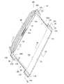
サンシェード装置SDは、図3にて示すごとく、シェード30と、取っ手部材40と、前側及び後側の各左右一対の摺動部材50と、補強部材60とを備えている。 The sunshade device SD includes a
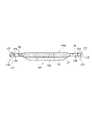
シェード30は、複数の部材を積層して矩形板状に構成されており、当該シェード30は、図8にて示すシェード用基材80を後述のように賦形して形成される。当該シェード用基材80は、シェード30の基になるものであって、具体的には、例えばスタンピング成形によりシェード30の形状に賦形する前のものである。ここで、シェード30は、図10にて示す賦形済みのシェード用基材80の前後方向縦断面形状に相当する前後方向縦断面形状を有している。 The
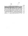
当該シェード用基材80は、図8にて示すごとく、発泡ウレタンからなる主材80aに、その表面側からガラス繊維マット80b、接着フィルム80c及び表皮80dを順に積層するととともに、その裏面側からガラス繊維マット80e及び接着フィルム付きの裏皮80fを順に積層して構成されている。 As shown in FIG. 8, the
主材80aの形成材料である発泡ウレタンは、本第1実施形態では、熱硬化性樹脂を発泡させたものを用いているが、これに限らず、熱可塑性樹脂を発泡させたものを用いてもよい。 In the first embodiment, the foamed urethane, which is the material for forming the
ガラス繊維マット80b、80eは、主材80aをその両側から挟持するように当該主材80aに積層されて、当該シェード用基材80の剛性を向上させている。なお、主材80aとガラス繊維マット80b、80eとは、本第1実施形態では、主材80aの表面に塗布した触媒と樹脂とにより接着されている。 The
また、表皮80dは、織物、レザー或いは不織布等からなり、裏皮80fは、不織布からなる。なお、表皮80dは、その表面(車室11内側の面)にて、車室11内を臨んでいる。 The
本第1実施形態では、上述したごとく、ガラス繊維マット80bと表皮80dとの接着は、接着フィルム80cによってなされ、ガラス繊維マット80eと裏皮80fとの接着は、裏皮80fに付けられた接着フィルムによってなされている。いずれにしても、当該接着は、接着フィルムにてなされているが、これに限らず、接着剤を用いてもよい。 In the first embodiment, as described above, the
取っ手部材40は、図3にて示すごとく、シェード30の前側左右方向中央部に設けられている。なお、図3において、図示左側及び右側が、それぞれ、シェード30の前側及び後側に対応する。 As shown in FIG. 3, the
取っ手部材40は、図3にて示すごとく、シェード30の前側端部の左右方向中央部位に設けられており、当該取っ手部材40は、指掛け部40a、フランジ部40b及びリブ部40c(以下、フランジリブ部40cともいう)を一体的に有するように、樹脂による一体成形でもって形成されている。 As shown in FIG. 3, the
指掛け部40aは、U字状窪み部41及び鍔部42を有している。U字状窪み部41は、シェード30の前側端部の左右方向中央部位に形成してなるスリット部31(図5参照)にその表面側から裏面側にかけて縦断面U字状となるように形成されて嵌着されており、当該U字状窪み部41は、シェード30のスリット部31の表面側へ開口するように、底壁部41aと、この底壁部41aの外周部から筒状に延出する周壁部41bとにより構成されている。なお、周壁部41bは、シェード30のスリット部31内に嵌着されている。 The
鍔部42は、U字状窪み部41の開口端部(周壁部41bの外端部)からシェード30の表面30aに沿い外方へ環状に延出するように形成されている。これにより、当該鍔部42は、後述のように、フランジ部40bと共にシェード30のスリット部31の外周部を挟持するとともに、当該スリット部31の周壁部41bからの抜け止めを防止する役割を果たす。 The
フランジ部40bは、シェード30の前側端部にて、当該シェード30の裏面30bに沿い指掛け部40aの周壁部41bの底側外周部位から外方へ環状に延出するように形成されており、当該フランジ部40bは、シェード30の前側端部の左右方向中央部位をその裏面側から受承して支持するとともに、シェード30をそのスリット部31の外周部にて挟持する。本第1実施形態において、フランジ部40bのうちの指掛け部41の図5にて図示右側側部位43aは、フランジ部40bのうちの指掛け部41の図5にて図示左側側部位43bよりも厚肉状に形成されることで、フランジ部40bの強度を向上させている。なお、指掛け部41の肉厚は、フランジ部40bのうちの指掛け部41の図5にて図示左側側部位と同様である。 The
フランジリブ部40cは、フランジ部40bをその裏面側から補強する役割を果たすもので、当該フランジリブ部40cは、フランジ部40bの指掛け部41の前側部位からその裏面側へ延出するように形成されている。ここで、当該フランジリブ部40cは、フランジ部40bの上記前側部位にその裏面に沿い左右方向に延出するように形成されている。 The
前側及び後側の各左右一対の摺動部材50のうち、前左右両側摺動部材50は、図3から分かるように、シェード30の左右両側端部の各前側部位に組み付けられており、一方、後左右両側摺動部材50は、図3から分かるように、シェード30の左右両側端部の各後側部位に組み付けられている。なお、本第1実施形態において、前左右両側摺動部材50は、それぞれ、前左側摺動部材50及び前右側摺動部材50といい、後左右両側摺動部材50は、それぞれ、後左側摺動部材50及び後右側摺動部材50ともいう。 Of the pair of left and right sliding
しかして、前左側摺動部材50及び後左側摺動部材50が、案内レール装置GRの左側レールGRa内に挿入される一方、前右側摺動部材50及び後右側摺動部材50が案内レール装置GRの右側レールGRa内に挿入される。このような状態において、乗員がその手により車室11内にて取っ手部材40の指掛け部40aに指をかけて、前後方向に力を加えると、サンシェード装置SDは前後方向へ案内レール装置GRに沿い摺動する(図1及び図2参照)。 Thus, the front
なお、補強部材60は、補強板からなるもので、当該補強部材60は、シェード30の後端部にその裏面側に沿いリベット等により組み付けられて、シェード30をその後端部側から補強する役割を果たす。 The reinforcing
次に、サンシェード装置SDの製造方法について図6を参照して説明する。まず、基材形成工程S1において、シェード30の基となる基材80(図7参照)が次のようにして形成される。 Next, a method for manufacturing the sunshade device SD will be described with reference to FIG. First, in the base material forming step S1, the base material 80 (see FIG. 7) that forms the base of the
当該基材形成工程S1においては、図7にて示すごとく、まず、発泡ウレタンからなる板状の主材70を準備する。このとき、主材70の表面と裏面には、上述した触媒と樹脂が塗布されているものとする。 In the base material forming step S1, as shown in FIG. 7, first, a plate-like
次に、ガラス繊維マット71、接着フィルム72及び表皮73を、主材70にその表面側から順次積層するととともに、ガラス繊維マット74及び接着フィルム付きの裏皮75を主材70にその裏面側から順次積層する(図7参照)。なお、ガラス繊維マット71、接着フィルム72、表皮73、ガラス繊維マット74及び接着フィルム付きの裏皮75は、以下、それぞれ、基材構成部材71、72、73、74及び75ともいう。また、上述のような主材70と、この主材70に積層される各基材構成部材71、72、73、74及び75とからなる構成は、以下、積層構成体ともいう。なお、主材70は、両ガラス繊維マット71、74の間に挟持されるように、これらガラス繊維マット71、74の全長に合せた長さを有する。 Next, the
しかして、このような積層構成体を所定の長さで切断すると、シェード30の基になる上述のシェード用基材80が形成される(図7参照)。ここで、当該シェード用基材80は、主材70に対応する主材80a、並びにガラス繊維マット71、接着フィルム72、表皮73、ガラス繊維マット74及び接着フィルム付きの裏皮75にそれぞれ対応するガラス繊維マット80b、接着フィルム80c、表皮80d、ガラス繊維マット80e及び接着フィルム付きの裏皮80fでもって構成される(図8参照)。 When such a laminated structure is cut to a predetermined length, the aforementioned
そして、上述した切断と同時に、スリット部80g(シェード30のスリト孔部31に対応)が、シェード用基材80のうちの取っ手部材40が形成される部位、すなわち前端側左右方向中央部にて、シェード用基材80の表面から裏面にかけて形成される(図7及び図8参照)。 Simultaneously with the cutting described above, the
次に、上述した基材形成工程S1の処理後基材投入工程S2において、上型110を下型150から上動させることで、金型装置100を開く。このような段階にて、シェード用基材80を、上型110と下型150との間に投入する(図9参照)。但し、シェード用基材80の金型装置100への投入前においては、シェード用基材80は、賦形のために加熱軟化されるが、当該加熱軟化工程についての詳細な説明は、省略する。 Next, in the post-treatment substrate loading step S2 of the substrate forming step S1 described above, the
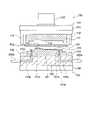
ここで、金型装置100の構成について説明すると、当該金型装置100は、図8或いは図9にて示すごとく、上型110(可動型110)及び下型150(固定型150)を備えて、スタンピング成形と樹脂射出成形とを略同時に行うように構成されている。 Here, the configuration of the
上型110は、矩形状の上型本体111を備えており、当該上型本体111は、4本のガイドポスト112の内側にて、矩形状の取り付け板113にその下面側から固定されている。一方、下型150は、矩形状の下型本体151を備えており、当該下型本体151は、複数のガイドブッシュ152の内側にて、マニホールド板153にその上面から固定されている。なお、マニホールド板153は、取り付け板154にその上面側から固定されている。 The
しかして、当該金型装置100は、上型110の下型150への下動に伴い、上型本体111を、後述のように、シェード用基材80を介し、下型本体151に押圧して、当該シェード用基材80をシェード30の形状となるようにスタンピング成形するとともに、シェード用基材80を介し上型本体111と下型本体151との間に形成されるキャビティC内に溶融樹脂を充填することで、シェード30と取手40との一体成形を行うようになっている。 As the
ここで、上型110の下型150への下動及び当該下型150からの上動は、上型110の取り付け板113に装着してなる油圧式昇降シリンダ120により行われる。なお、下型150は、油圧式昇降シリンダ120により、所定のストロークだけ昇降駆動される。 Here, the downward movement of the
また、複数のガイドポスト112は、取り付け板113の下面の4隅部に下方へ突出するように設けられており、当該複数のガイドポスト112は、上型110の下動に伴い、マニホールド板153の上面の4隅部から突出する各筒状のガイドブッシュ152に挿入されて、上型110の下型150に対する位置決めを行う役割を果たす。 A plurality of
上型本体111の下型本体151に対する対向面114(以下、上側成形面114ともいう)は、賦形済みのシェード用基材80(図9或いは図10参照)、換言すれば、シェード30の図10にて図示上面(室内側面)の前後方向縦断面形状に相当する前後方向縦断面形状を有する。一方、下型本体151の上型本体111に対する対向面154(以下、下型成形面154ともいう)は、賦形済みのシェード用基材80の図10に図示下面(室外側面)の前後方向縦断面形状に対応する前後方向縦断面形状を有する。 The facing
上述したキャビティCは、フランジ部用キャビティ部C1、リブ部用キャビティ部C2及び指掛け部用キャビティ部C3でもって構成されている。 The above-described cavity C is composed of a flange portion cavity portion C1, a rib portion cavity portion C2, and a finger rest portion cavity portion C3.
ここで、フランジ部用キャビティ部C1は、取手40のフランジ部40bに対応する中空形状を有し、フランジリブ部用キャビティ部C2は、取手40のフランジリブ部40cに対応する中空形状を有し、指掛け部用キャビティ部C3は、取手40の指掛け部40aに対応する中空形状を有する。 Here, the flange portion cavity portion C1 has a hollow shape corresponding to the
しかして、フランジ部用キャビティ部C1は、図10にて示すごとく、賦形済みのサンシェード本体用基材80の図示下面と下型本体151の上型本体111に対する対向面155(以下、下型成形面155ともいう)との間に形成されている。これに伴い、下型成形面155は、図10にて示す断面形状から分かるように、取手40のフランジ部40bの外形形状であるフランジ部用キャビティ部C1の中空形状に対応するように切り欠き形成されている。 Thus, as shown in FIG. 10, the flange portion cavity portion C1 is composed of the bottom surface of the formed sunshade main
フランジリブ部用キャビティ部C2は、図10にて例示するごとく、フランジ部用キャビティ部C1から下型本体151内に向け壁状の凹部として形成されている。また、指掛け部用キャビティ部C3は、賦形済みのサンシェード本体用基材80のスリット部80gを後述のように図18にて示すごとく開いた状態にてフランジ部用キャビティ部C1のうちの当該スリット部80gの近傍部位からスリット部80gを介し上型本体111の上型成形面114のうちのスリット部80gの近傍部位にかけて形成される。なお、スリット部80gは、シェード30のスリット部31に対応する。 As illustrated in FIG. 10, the flange rib cavity portion C2 is formed as a wall-shaped concave portion extending from the flange portion cavity portion C1 toward the inside of the lower die
また、マニホールド板153は、流路153a、153bを有しており、これら流動路153a、153bのうち、流路153aは、その外端開孔部にて、樹脂射出成形機200aにその射出ノズルを介し接続されており、当該流路153aは、その内端開孔部にて、下型本体151の流路151aを介しゲート151bに連通する。ここで、流路151aは、ゲート151bを介しフランジ部用キャビティ部C1内に連通する(図10参照)。これに伴い、樹脂射出成形機200aは、溶融樹脂を、両流路153a、151a及びゲート151bを介してフランジ部用キャビティ部C1内に射出する。 Further, the
一方、流路153bは、その外端開孔部にて、樹脂射出成形機200bにその射出ノズルを介し接続されており、当該流路153bは、その内端開孔部にて、下型本体151の流路151cを介しゲート151dに連通する。ここで、流路151cは、ゲート151dを介しフランジ部用キャビティ部C1内に連通する(図10参照)。これに伴い、樹脂射出成形機200bは、溶融樹脂を、両流路153b、151c及びゲート151dを介してフランジ部用キャビティ部C1内に射出する。 On the other hand, the
なお、本第1実施形態では、金型装置100において、上型110及び下型150が、図9にて示すごとく、上下に位置するよう構成されているが、これに代えて、上型110及び下型150が、左右に位置するように構成されていてもよい。 In the first embodiment, in the
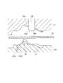
上述のように基材投入工程S2の処理をした後、基材賦形工程S3に進む。図10は、当該基材賦形工程S3にて、シェード用基材80が、上型110の下動及び可動駒130の下動のもとに、シェード30の形状に賦形されたときの様子を示している。 After performing the processing of the base material input step S2 as described above, the process proceeds to the base material shaping step S3. FIG. 10 shows a state in which the
以下、基材賦形工程S3の処理について詳細に説明する。図11は、基材賦形工程S3に進んだ直後の状態を示している。ここで、可動駒130は、矩形棒状体からなるもので、当該可動駒130は、上型110の取り付け板113及び上型本低111に亘り形成してなる摺動穴部(図示しない)内に上下方向に摺動可能に嵌装されて、シェード用基材80のスリット部80gに対向するように位置している。なお、当該可動駒130は、昇降シリンダ120とは別の油圧装置(図示しない)により、上下方向に摺動される。 The processing of the base material shaping step S3 will be described in detail below. FIG. 11 shows the state immediately after proceeding to the base material shaping step S3. Here, the
可動駒130は、後述のごとく、シェード用基材80のスリット部80gを押し広げ孔部H(図13参照)として押し広げるとともに指掛け部用キャビティ部C3を形成する役割を果たす。ここで、指掛け部用キャビティ部C3は、上型本体111の上型成形面114のうちの可動駒130の軸方向中間部位の外周側成形面部に浅い凹状に形成してなる凹部114a(取っ手部材40の指掛け部40aの鍔部42に対応)と、シェード用基材80のスリット部80gの押し広げ孔部Hと可動駒130の先端部との間の環状空隙部G(図15参照)とによって形成される。なお、可動駒130は、その底面130aにて、フランジ部用キャビティ部C1のうち底面130aに対する対応部位の傾きに応じた傾きで傾斜している(図12参照)。 As will be described later, the
しかして、基材賦形工程S3において、可動駒130が、その初期位置(図11参照)から図12にて示すごとく下動を開始し、シェード用基材80のスリット部80gに到達して、当該スリット部80gを押圧する。これにより、スリット部80gは、押し広げ孔部Hとして、可動駒130の底面130a及びその近傍面130bによって下方へ押し広げられる(図13参照)。 Then, in the base material shaping step S3, the
当該可動駒130の下動に併せて、上型110が下動し、図10或いは図146にて示すごとく、下型150に係合することで金型装置100を閉じる。これに伴い、シェード用基材80が上型本体111及び下型本体151によりシェード30の形状に賦形される。この賦形は、スリット部80gの押し広げ孔部Hとして形成にあわせてなされる。当該押し広げ孔部Hは、可動駒130の先端部との間に上記環状空隙部を形成する役割を果たす。 Along with the downward movement of the
次に、上述のように金型装置100を閉じた状態において、可動駒130のみを上記油圧装置により所定の高さだけ上動させる(図15参照)。これにより、可動駒130とシェード用基材80との密接状態(図14参照)が解消され、可動駒130とシェード用基材80との間に、環状空隙部G(以下、環状空隙部Gという)が形成される。当該環状空隙部Gは、上述したごとく、凹部114aとともに、指掛け部用キャビティ部C3を形成する。 Next, with the
また、可動駒130が、上述したごとく、所定の高さだけ上昇することにより、フランジ部用キャビティ部C1が、その可動駒130の底面部130aに対する対応部位にて、可動駒130の底面部130aまで拡張される。ここで、フランジ部用キャビティ部C1の可動駒130の底面部130aに対する対応部位と可動駒130の底面部130aとの間に形成される拡張空間部が取っ手部材40の指掛け部40aの底壁部41aに対応し、当該底壁部41aの剛性を高める役割を果たす。 Further, as the
上述のように基材賦形工程S3の処理を行った後、溶融樹脂充填工程S4において、樹脂射出成形機200aから射出される溶融樹脂MSが、流路153a、流路151a及びゲート151bを介し、キャビティCのフランジ部用キャビティ部C1及び複数のリブ部用の複数のキャビティ部C2内に充填されるとともに、樹脂射出成形機200bから射出される溶融樹脂MSが、流路153b、流路151c及びゲート151dを介し、キャビティCのフランジ部用キャビティ部C1、複数のリブ部用の複数のキャビティ部C2及び指掛け部用キャビティ部C3内に順次充填される(図16にて図示矢印参照)。このことは、溶融樹脂MSが、図17及び図18にて示すごとく、キャビティCの内部の全体に亘り充填されることを意味する。 After the substrate shaping step S3 is performed as described above, in the molten resin filling step S4, the molten resin MS injected from the resin
然る後、溶融樹脂硬化工程S5において、キャビティC内に充填された溶融樹脂が、当該充填後、冷却されて硬化していく。このことは、キャビティC内の溶融樹脂がその硬化に伴い取っ手部材40として成形されることを意味する。なお、当該硬化後、可動駒130が、さらに、上動されて、キャビティ部C3の中空部内から脱出する。このとき、キャビティC3内の溶融樹脂は、その硬化に伴い、取っ手部材40の指掛け部40aとしての形状を維持し得る。 Thereafter, in the molten resin curing step S5, the molten resin filled in the cavity C is cooled and hardened after the filling. This means that the molten resin in the cavity C is molded as the
これにより、シェード用基材80からスタンピング形成してなるシェード30が、上型110及び下型150の間において、取っ手部材40と共に、一体的に、樹脂による一体成形でもって、一体成形品として形成される(図19参照)。 As a result, the
このような溶融樹脂硬化工程S5の処理後、次の一体成形品取り出し工程S6において、上型110を下型150から上動させて金型装置100を開く。このとき、シェード30と取っ手部材40との一体成形品(図19参照)が、下型150の下型本体151上に留まっている。従って、当該一体成形品が、下型本体151から取り出される。 After the molten resin curing step S5, the
然る後、補強部材組み付け工程S7において、補強部材60が、シェード30の後端部に沿いその裏面側からリベット等により組み付けられる。これにより、当該補強部材60は、シェード30をその後端部側から補強し得る。 After that, in the reinforcing member assembling step S7, the reinforcing
ついて、摺動部材組み付け工程S8において、前左側摺動部材50及び後左側摺動部材50が、それぞれ、シェード30の左側端部の前側部位及び後側部位に組み付けられるとともに、前右側摺動部材50及び後右側摺動部材50が、それぞれ、シェード30の右側端部の前側部位及び後側部位に組み付けられる。以上により、サンシェード装置SDの製造及び組み立てが完了する。 Accordingly, in the sliding member assembling step S8, the front
以上説明した本第1実施形態によれば、上述のように製造及び組み立てが完了したサンシェード装置SDにおいては、取っ手部材40が、シェード用基材80のスリット部80gを有効に活用した樹脂射出成形により、単一の部品として一体的に成形される。このため、当該取っ手部材40を製造するにあたり、従来のように2部品からなる取っ手を製造する場合のように別々の金型を必要とすることなく、製造コストを軽減することができる。 According to the first embodiment described above, in the sunshade device SD that has been manufactured and assembled as described above, the
また、取っ手部材40が、樹脂を用いた射出成形のもとに、シェード30と一体的に成形されるので、従来のように取っ手をサンシェードとは別途製造した上で、当該取っ手をサンシェードに組み付ける作業は、全く、不必要となり、サンシェード装置SDの製造組み付け作業効率が大幅に改善され得る。 In addition, since the
ここで、当該サンシェード装置SDにおいて、シェード30は、主として、発泡ウレタンからなる主材70をその両面側からガラス繊維マット71、74により挟持して構成されている。従って、シェード30の軽量化を図ることができる。 Here, in the sunshade device SD, the
また、取っ手部材40の指掛け部40aに環状壁部40cを一体的に成形し、当該フランジ部40bによりシェード30をその下方から受承して支持するようにしたので、シェード30の全体としての剛性をさらに高めることができる。 In addition, since the ring-shaped
ここで、フランジ部40bは、上述のごとく厚肉部43aを有することで部分的な補強を増強してなり、また、当該フランジ部40bにはフランジリブ部40cを上述のごとく一体的に形成することで、シェード30のその裏面側からの支持や当該シェード30の剛性をさらに高めている。 Here, the
その結果、シェード30の全体としての軽量化を確保し得るとともに、当該シェード30の全体として十分な剛性を確保することできる。 As a result, the weight reduction of the
(第2実施形態)
図20は、本発明に係るサンシェード装置の第2実施形態を示している。本第2実施形態にいうサンシェード装置(以下、サンシェード装置SD1という)は、上記第1実施形態にいうサンシェード装置SDに代えて、上記第1実施形態にて述べた案内レール装置GRを介し、自動車の窓Wの窓用開口部W2に対し前後方向に摺動可能に支持されるようになっている。(Second embodiment)
FIG. 20 shows a second embodiment of a sunshade device according to the invention. The sunshade device (hereinafter referred to as sunshade device SD1) according to the second embodiment is provided by replacing the sunshade device SD according to the first embodiment with the guide rail device GR described in the first embodiment. It is supported so as to be slidable in the front-rear direction with respect to the window opening W2 of the window W.
サンシェード装置SD1は、図20にて示すごとく、シェード160と、上記第1実施形態にて述べた取っ手部材40と、前左右両側摺動部材170及び後左右両側摺動部材170と、補強部材180とを備えている。 As shown in FIG. 20, the sunshade device SD1 includes a
シェード160は、矩形状のシェード本体160aと、前左右両側シェード片160b及び後左右両側シェード片160bとを備えており、当該シェード160は、シェード本体160a、前左右両側シェード片160b及び後左右両側シェード片160bを一体的に有するように、上記第1実施形態にて述べたシェード用基材80(図7参照)の左右方向幅を幅広にしてなるシェード用幅広基材(図示しない)から形成されている。 The
シェード本体160aは、上記第1実施形態にて述べたシェード30に対応するもので、当該シェード本体160aには、シェード30のスリット部31に対応するスリット部167(図21参照)が形成されている。 The shade
前左右両側シェード片160b及び後左右両側シェード片160bは、共に同一形状に形成されており、前左右両側シェード片160bは、シェード本体160aの前端部の左右両側端部から互いに左右方向に離れるように延出されており、一方、後左右両側シェード片160bは、シェード本体160aの後端部の左右両側端部から互いに左右方向に離れるように延出されている。なお、前左右両側シェード片160bのシェード本体160aの前端部の左右両側端部からの延出長さは同一となっている。また、後左右両側シェード片160bのシェード本体160aの後端部の左右両側端部からの延出長さは同一となっている。 The front left and
また、前左右両側シェード片160bの各々は、図21にて示すごとく、前側片部161、中側片部162及び後側片部163と、連結片部164とでもって、前側開口部165及び後側開口部166を形成するように、E字状に形成されている。換言すれば、前左側シェード片160bは、シェード本体160aの前端部の左端部、前側片部161、中側片部162及び連結片部164の前側部位で包囲するように、前側開口部165を矩形状に形成するとともに、前右側シェード片160bは、シェード本体160aの前側端部の右端部、中側片部162、後側片部163及び連結片部164の後側部位で包囲するように、後側開口部166を矩形状に形成する。 21, each of the front left and right
また、後左右両側シェード片160bの各々は、同様に、前側片部161、中側片部162及び後側片部163と、連結片部164とでもって、前側開口部165及び後側開口部166を形成するように、E字状に形成されている。換言すれば、後左側シェード片160bは、シェード本体160aの後側端部の左端部、前側片部161、中側片部162及び連結片部164の前側部位で包囲するように、前側開口部165を矩形状に形成するとともに、後右側シェード片160bは、シェード本体160aの後側端部の右端部、中側片部162、後側片部163及び連結片部164の後側部位で包囲するように、後側開口部166を矩形状に形成する。 Similarly, each of the rear left and
本第2実施形態において、上記シェード用幅広基材は、その左右両側端部を、前左右両側シェード片160b及び後左右両側シェード片160bに対応する各部位を残すように切除することで、基材本体、前左右両側基材片及び後左右両側基材片を一体的に有するように構成されている。なお、上記基材本体は、シェード本体160aに対応し、上記前左右両側基材片は前左右両側シェード片160bに対応し、かつ、上記後左右両側基材片は後左右両側シェード片160bに対応する。 In the second embodiment, the wide base material for the shade is cut off from the left and right side ends so as to leave portions corresponding to the front left and right
また、本第2実施形態にいう上記シェード用幅広基材において、上記基材本体には、シェード用基材80のスリット部80gに対応するスリット部が形成されており、当該スリット部は、シェード本体160aのスリット部167に対応する。また、上記シェード用幅広基材は、その左右方向幅にて、それぞれ、上記第1実施形態にいうシェード用基材80の左右方向幅を前左右両側シェード片160b及び後左右両側シェード片160bのシェード本体160aからの延出長さだけ広くするように形成されている。 In the wide base material for shade according to the second embodiment, a slit corresponding to the
これに伴い、上記第1実施形態にて述べた主材70及び各基材構成部材71、72、73、74及び75とからなる積層構成体(図7参照)も、その左右方向幅にて、同様に、前左右両側シェード片160b及び後左右両側シェード片160bの延出長さだけ幅広となっている。 Along with this, the laminated structure (see FIG. 7) consisting of the
また、本第2実施形態においては、上記第1実施形態にて述べた取っ手部材40(図5参照)が採用されており、当該取っ手部材40は、上記第1実施形態にて述べたシェード30に代えて、シェード本体160aの前側端部の左右方向中央部位に左右方向に沿い形成されている。 Further, in the second embodiment, the handle member 40 (see FIG. 5) described in the first embodiment is adopted, and the
本第2実施形態にいう取っ手部材40は、上記第1実施形態にいう取っ手部材と同様に、指掛け部40aと、フランジ部40bと、フランジリブ部40cとにより構成されている。 A
本第2実施形態にいう取っ手部材40において、指掛け部40aは、そのU字状窪み部41(図5参照)にて、シェード本体160aのスリット部167(図21参照)にその表面側から裏面側にかけてU字状となるように形成されて嵌着されており、当該U字状窪み部41は、シェード本体160aのスリット部167の表面側へ開口するように、底壁部41a及び周壁部41bでもって構成されている。ここで、周壁部41bは、図5から理解されるように、シェード30に代わるシェード本体160aのスリット部167内に介装されている。また、鍔部42は、スリット部31に代わるスリット部167の開口端部からシェード本体160aの表面に沿うように外方へ環状に延出されている。 In the
また、本第2実施形態にいう取っ手部材40において、フランジ部40bは、シェード本体160aの裏面に沿い指掛け部40aの周壁部41bの底側外周部位から外方へ環状に延出するように形成されており、当該フランジ部40bは、シェード本体160aの前側端部をその裏面側から受承して支持する。また、当該フランジ部40bは、指掛け部40aの鍔部42と共に、シェード本体160aのスリット部167の外周部を挟持する。 Further, in the
また、本第2実施形態では、フランジ部40bは、左右両側連結板部90a(図20参照)を介し補強部材180の補強板部181(後述する)に一体的に連結されている。 In addition, in the second embodiment, the
ここで、左右両側連結板部90aは、図22にて例示するごとく、細幅板状に形成されており、当該左右両側連結板部90aのうち左側連結板部90aは、フランジ部40bの左側端部からシェード本体160aの前側端部にその裏面に沿い左側方向に延出するとともに、シェード本体160aの前側端部の左端部からL字状に折れ曲がってシェード本体160aの左側端部にその裏面に沿い後側方向に延出して補強部材180の補強板部181の左端部に一体的に連結されている。これにより、当該左側連結板部90aは、シェード本体160aを、その前側端部のうちの左側部にてその下方から受承して支持することで、補強する役割を果たす。 Here, the left and right side connecting
一方、右側連結板部90aは、フランジ部40bの右側端部からシェード本体160aの前側端部にその裏面に沿い右側方向に延出するとともに、シェード本体160aの前側端部の右端部からL字状に折れ曲がってシェード本体160aの右側端部にその裏面に沿い後側方向に延出して補強部材180の補強板部181の右端部に一体的に連結されている。これにより、当該右側連結板部90aは、シェード本体160aを、その前側端部のうちの右側部にてその下方から受承して支持することで、補強する役割を果たす。 On the other hand, the right connecting
本第2実施形態では、左右両側リブ部90bが、図22にて例示するごとく、左右両側連結板部90aにその各裏側へ板状に延出するように形成され、かつ、左右両側連結板部90aの各長手方向に沿い延在するように形成されている。これにより、当該左右両側リブ部90bは、左右両側連結板部90aを補強する役割を果たす。なお、左右両側リブ部90bは、取っ手部材40のフランジリブ部40cから互いに逆方向に延出されており、当該左右両側リブ部90bは、その各延出端部にて、補強部材180の中央リブ部182の左右両端部に一体的に連結されている。また、左右両側リブ部90bは、以下、左右両側連結板リブ部90bともいう。 In the second embodiment, as shown in FIG. 22, the left and right
また、本第2実施形態にいう取っ手部材40においても、フランジリブ部40cは、フランジ部40bをその全体に亘りその裏面側から補強すべく、フランジ部40bの上記前側部位からその裏面側へ壁状に延出するように形成されている。 Also in the
次に、4つの摺動部材170の構成について説明すると、当該4つの摺動部材170のうち、前左右両側摺動部材170は、シェード本体160aの前側端部の左右両端部に対し、上記基材本体のシェード本体160aとしての賦形の際に、前左右両側シェード片160bを介し樹脂による成形でもって形成されている(図20或いは図21参照)。また、後左右両側摺動部材170は、シェード本体160aの後側端部の左右両端部に対し、上記基材本体のシェード本体160aとしての賦形の際に、後左右両側シェード片160bを介し樹脂による成形でもって形成されている(図20或いは図21参照)。 Next, the configuration of the four sliding
前左右両側摺動部材170及び後左右両側摺動部材170は、シェード本体160aに対する各形成位置を除き、共に、同一の構成を有するように形成されている。そこで、これらの摺動部材170のうちの前左側摺動部材170を例にとりその構成について説明する。 The front left and right
前左側摺動部材170は、摺動部材本体170a、上側押圧部170b及び下側押圧部170cを有するように、上述した基材本体のシェード本体160aとしての賦形の際に、樹脂による一体成形でもって、前左側シェード片160bに形成されている(図23及び図25のいずれか参照)。 The front
摺動部材本体170aは、前左側シェード片160bをその外周及び延出端側から覆うように短冊板状に形成されている。この形成に伴い、前左側シェード片160bが、その前側片部161、中側片部162及び後側片部163並びに連結片部164にて、摺動部材本体170aを形成する樹脂により覆われる。これに伴い、前後両側開口部164、165が、その各中空部にて、摺動部材本体170aを形成する樹脂でもって埋められる(図23参照)。 The sliding member
ここで、摺動部材本体170aは、その両面にて、前側片部161、中側片部162及び後側片部163並びに連結片部164の各両面に対し間隔をおいて平行となっている。また、摺動部材本体170aの前端面は、前側片部161の前端面に対し間隔をおいて平行となっており、摺動部材本体170aの後端面は、後側片部163の後端面に対し間隔をおいて平行となっている。 Here, both surfaces of the sliding member
上側押圧部170bは、摺動部材本体170aの図23にて図示上面中央側部位から上方へ凸な緩やかな湾曲形状にて膨出するように形成されており、一方、下側押圧部170cは、摺動部材本体170aの図23にて図示下面中央側部位から下方へ凸な緩やかな湾曲形状にて膨出するように形成されている。 The upper
これに伴い、上側押圧部170b及び下側押圧部170cは、摺動部材本体170aの中央部位及び中側片部162を介し互いに対向するようになっている。ここで、前左側摺動部材170において、上側押圧部170b及び下側押圧部170cは、中側片部162を押圧可能な弾力性を有する。なお、上側押圧部170bの頂部と摺動部材本体170aの上面との間の距離は、下側押圧部170cの頂部と摺動部材本体170aの下面との間の距離と同一である。 Along with this, the upper
また、前左側摺動部材170は、図23或いは図25にて示すごとく、前上下両側凸部171及び後上下両側凸部172を有している。前上下両側凸部171は、摺動部材本体170aの前側部位の上下両面から互いに外方へ縦断面半球状に隆起するように、樹脂による一体成形でもって形成されている。一方、後上下両側凸部172は、摺動部材本体170aの後側部位の上下両面から互いに外方へ縦断面半球状に隆起するように樹脂による一体成形でもって形成されている。なお、各凸部171、172の半径は共に同一である。 23 or 25, the front
本第2実施形態において、上側押圧部170bの頂部と摺動部材本体170aの上面との間の距離は、前上側凸部171の頂部と摺動部材本体170aの上面との間の距離或いは後上側凸部172の頂部と摺動部材本体170aの上面との間の距離よりも長くなっている。一方、下側押圧部170bの頂部と摺動部材本体170aの下面との間の距離は、前下側凸部171の頂部と摺動部材本体170aの下面との間の距離或いは後下側凸部172の頂部と摺動部材本体170aの下面との間の距離よりも長くなっている。 In the second embodiment, the distance between the top of the upper
残りの前右側摺動部材170、上述した基材本体のシェード本体160aとしての賦形の際に、後左側摺動部材170及び後右側摺動部材170は、それぞれ、シェード160の前右側シェード片160b、後左側シェード片160b及び後右側シェード片160bに対し、前左側摺動部材170の前左側シェード片160bに対する樹脂による成形と同様に、前左側摺動部材170と同様の構成にて、樹脂による成形でもって形成されている。 The remaining front
このように構成してなる前左側摺動部材170及び後左側摺動部材170は、上記第1実施形態にて述べた前左側摺動部材50及び後左側摺動部材50に代えて、案内レール装置GRの左側レールGRa内に挿入される一方、前右側摺動部材170及び後右側摺動部材170は、上記第1実施形態にて述べた前右側摺動部材50及び後右側摺動部材50に代えて、案内レール装置GRの右側レールGRa内に挿入される。 The front
これに伴い、前左側摺動部材170が、前上下両側凸部171及び後上下両側凸部172にて、左側レールGRaの上側レール壁GR1及び下側レール壁GR2と摺接可能となるように、上下両側押圧部170b、170cにて、摺動部材本体170aの前後方向中央部位を介し前左側シェード片160bの中央片部162をその両面から押圧しながら、左側レールGRaの上側レール壁GR1及び下側レール壁GR2により挟持される。一方、前右側摺動部材170が、前上下両側凸部171及び後上下両側凸部172にて、右側レールGRaの上側レール壁GR1及び下側レール壁GR2と摺接可能となるように、上下両側押圧部170b、170cにて、摺動部材本体170aの前後方向中央部位を介し前右側シェード片160bの延出部162をその両面から押圧しながら、右側レールGRaの上側レール壁GR1及び下側レール壁GR2により挟持される。 Along with this, the front
また、同様にして、後左側摺動部材170が、前上下両側凸部171及び後上下両側凸部172にて、左側レールGRaの上側レール壁GR1及び下側レール壁GR2と摺接可能となるように、上下両側押圧部170b、170cにて、摺動部材本体170aの前後方向中央部位を介し後左側シェード片160bの延出部162をその両面から押圧しながら、左側レールGRaの上側レール壁GR1及び下側レール壁GR2により挟持される。一方、後右側摺動部材170が、前上下両側凸部171及び後上下両側凸部172にて、右側レールGRaの上側レール壁GR1及び下側レール壁GR2と摺接可能となるように、上下両側押圧部170b、170cにて、摺動部材本体170aの前後方向中央部位を介し後右側シェード片160bの延出部162をその両面から押圧しながら、右側レールGRaの上側レール壁GR1及び下側レール壁GR2により挟持される。 Similarly, the rear
以上のようにして、サンシェード装置SD1は、案内レール装置GRに対し安定的に摺動可能に組み付けられる。このような状態において、乗員がその手により車室11内にて本第2実施形態にいう取っ手部材40の指掛け部40aに指をかけて、前後方向に力を加えると、サンシェード装置SD1が、上記第1実施形態にて述べたサンシェード装置SDに代えて、前後方向へ案内レール装置GRに沿い摺動する。 As described above, the sunshade device SD1 is stably and slidably assembled to the guide rail device GR. In this state, when the occupant puts his or her finger on the
補強部材180は、図20にて示すごとく、シェード160のシェード本体160aの後端部に設けられており、当該補強部材180は、図24にて示すごとく、補強板部181及び3つのリブ部182~184でもって、上述した基材本体のシェード本体160aとしての賦形の際に、樹脂による一体成形でもって形成されている。なお、当該リブ部182~184のうち、リブ部182は中央リブ部182ともいい、リブ部183は、前側補助リブ部183ともいい、リブ部184は、後側補助リブ部184ともいう。 As shown in FIG. 20, the reinforcing
補強板部181は、シェード本体160aの後端部にその左右方向に沿うように長手状に形成されており、当該補強板部181は、その左右方向両端部にて、左右両側連結板部90aの各延出端部に一体的に連結されている。ここで、当該補強板部181は、シェード本体160aの後端部をその裏面側から受承して支持することにより当該シェード本体160aをその後端部から補強する役割を果たす。 The reinforcing
3つのリブ部182~184は、補強板部181にその左右方向に沿うように長手状に形成されており、当該3つのリブ部182~184は、補強板部181に直交して当該補強板部181からその裏面側へ延出するように形成されている。 The three
当該3つのリブ部182~184のうち、中央リブ部182は、補強板部181の幅方向中央部からその裏面側へ延出するように形成されている(図24及び図25参照)。前側補助リブ部183は、補強板部181の幅方向前側部位からその裏面側へ延出するように形成されており、後側補助リブ部184は、補強板部181の幅方向後側部位からその裏面側へ延出するように形成されている。これにより、3つのリブ部182~184は、補強板部181を補強する役割を果たす。以上のことから、当該補強部材180は、シェード本体160aの後端部をその裏面側から補強する役割を果たすものといえる。 Among the three
次に、サンシェード装置SD1の製造方法について説明する。図6の基材形成工程S1においては、上記第1実施形態にて述べたシェード用基材80と同様の積層構造にて、シェード用幅広基材を形成する。但し、当該シェード用幅広基材は、上述したごとく、シェード用基材80よりも幅広に形成されている。 Next, a method for manufacturing the sunshade device SD1 will be described. In the base material forming step S1 of FIG. 6, a wide base material for shade is formed with a laminated structure similar to that of the
本第2実施形態において、当該シェード用幅広基材は、シェード本体160aに対応する基材本体、前左右両側シェード片160bに対応する前左右両側基材片及び後左右両側シェード片160bに対応する後左右両側基材片を有するように形成される。 In the second embodiment, the wide shade base material corresponds to the base material main body corresponding to the shade
ここで、上記前左右両側基材片は、上記基材本体の前側端部の左右両側端部から互いに逆向きに外方へ延出するように形成されるとともに、上記後左右両側基材片は、上記基材本体の後側端部の左右両側端部から互いに逆向きに外方へ延出するように形成される。 Here, the front left and right side base material pieces are formed so as to extend outward in mutually opposite directions from the left and right side end portions of the front side end portion of the base material main body, and the rear left and right side base material pieces are formed to extend outward in mutually opposite directions. are formed so as to extend outward in opposite directions from the right and left side ends of the rear end portion of the base material body.
また、上記基材本体には、シェード本体160aのスリット部167に対応するスリット部が形成されるとともに、前左右両側基材片及び後左右両側基材片の各々には、前左右両側シェード片160b及び後左右両側シェード片160bの各々の前後両側開口部165、166に対応する前後両側開口部が形成される(図21参照)。 Further, slit portions corresponding to the
基材投入工程S2において、上記シェード用幅広基材を、上記第1実施形態にて述べたシェード用基材80に代えて、上記第1実施形態にて述べた金型装置100を開いた状態にて、上型110と下型150との間に投入する。 In the base material input step S2, the
ついで、金型装置100は、上型110の下型150への下動に伴い、上型本体111を、上記第1実施形態にて述べたシェード用基材80に代わる上記シェード用幅広基材を介し、下型本体151に押圧して、当該シェード用幅広基材をシェード160の形状となるようにスタンピング成形するとともに、上記シェード用幅広基材を介し上型本体111と下型本体151との間に形成されるキャビティ(以下、本第2実施形態においても、キャビティCという)内に溶融樹脂を充填することで、シェード160、取手部材40、各摺動部材170及び補強部材180の一体成形を行う。 Next, as the
これに伴い、本第2実施形態にいうキャビティC及び金型装置100の各構成が、上記第1実施形態にいうキャビティC及び金型装置100の各構成から部分的に変更されているので、以下、この変更点について説明する。 Along with this, the configurations of the cavity C and the
上記第1実施形態においては、キャビティCが、上述のごとく、フランジ部用キャビティ部C1、フランジリブ部用キャビティ部C2及び指掛け部用キャビティ部C3により構成されている。ここで、フランジ部用キャビティ部C1は、取っ手部材40のフランジ部40cに対応し、フランジリブ部用キャビティ部C2は、取っ手部材40のフランジリブ部40cに対応し、また、指掛け部用キャビティ部C3は、取っ手部材40の指掛け部40aに対応する。 In the first embodiment, as described above, the cavity C is composed of the flange portion cavity portion C1, the flange rib portion cavity portion C2, and the finger rest portion cavity portion C3. Here, the flange portion cavity portion C1 corresponds to the
一方、本第2実施形態においては、上述したごとく、取っ手部材40のフランジ部40b、左側連結板部90a、補強板部181及び右側連結板部90aは、上述のように連結形成されて、四角環状板構造を構成する(図20参照)。 On the other hand, in the second embodiment, as described above, the
また、取っ手部材40のフランジリブ部40c、左側連結板リブ部90b、補強部材180の中央リブ部182及び右側連結板リブ部90bは、上述のように連結形成されて、四角環状リブ構造を構成する(図20参照)。なお、補強部材180の前後両側補助リブ部183、184は、それぞれ、単独のリブ構造を構成する。 The
これに伴い、本第2実施形態にいうキャビティCは、上記第1実施形態にいうキャビティC、即ち、フランジ部用キャビティ部C1、フランジリブ部用キャビティ部C2及び指掛け部用キャビティ部C3に加えて、左側連結板部用L字状キャビティ部C4(図20及び図22参照)、右側連結板部用L字状キャビティ部C4(図20及び図22参照)、補強板用キャビティ部C5(図20及び図24参照)、左側連結板リブ用キャビティ部C6(図22参照)、右側連結板リブ用キャビティ部C6(図22参照)及び前後両側補助リブ部用キャビティ部C7を有している。そして、これら左側連結板部用L字状キャビティ部C4、右側連結板部用L字状キャビティ部C4、補強板用キャビティ部C5、左側連結板リブ用キャビティ部C6、右側連結板リブ用キャビティ部C6及び前後両側補助リブ部用キャビティ部C7は、フランジ部用キャビティ部C1、フランジリブ部用キャビティ部C2及び指掛け部用キャビティ部C3と共に、上記シェード用幅広基材を介し、金型装置100の上型本体111と下型本体151との間に形成される。 Along with this, the cavity C referred to in the second embodiment is the cavity C referred to in the first embodiment, that is, in addition to the cavity C1 for the flange portion, the cavity portion C2 for the flange rib portion, and the cavity portion C3 for the finger hook portion. 20 and 22), an L-shaped cavity portion C4 for the right connecting plate portion (see FIGS. 20 and 22), and a reinforcing plate cavity portion C5 (see FIGS. 20 and 22). 20 and FIG. 24), a left connecting plate rib cavity portion C6 (see FIG. 22), a right connecting plate rib cavity portion C6 (see FIG. 22), and a cavity portion C7 for both front and rear auxiliary rib portions. The L-shaped cavity portion C4 for the left connecting plate portion, the L-shaped cavity portion C4 for the right connecting plate portion, the cavity portion C5 for the reinforcing plate, the cavity portion C6 for the left connecting plate rib, and the cavity portion for the right connecting plate rib C6 and the front and rear side auxiliary rib portion cavity portions C7, along with the flange portion cavity portion C1, the flange rib portion cavity portion C2, and the finger hook portion cavity portion C3, are connected to the
さらに、前左右両側摺動部材170及び後左右両側摺動部材170に対応する前左右両側摺動部材用キャビティ部C8及び後左右両側摺動部材用キャビティ部C8(図20参照)が、上述したシェード用幅広基材の前左右両側片及び後左右両側片を介し、上型本体111と下型本体151との間に形成される。なお、左側連結板部用L字状キャビティ部C4、右側連結板部用L字状キャビティ部C4、補強板用キャビティ部C5、左側連結板リブ用キャビティ部C6、右側連結板リブ用キャビティ部C6、左右両側補助リブ部用キャビティ部C7は、それぞれ、左側連結板部90a、右側連結板部90a、補強板部181、左側連結板部用リブ部90b、右側連結板部用リブ部90b、左右両側補助リブ部183、184に対応する。 Further, the front left/right sides sliding member cavity portion C8 and the rear left/right sides sliding member cavity portion C8 (see FIG. 20) corresponding to the front left/right
ついで、基材賦形工程S3において、可動駒130が、上記第1実施形態と同様にその初期位置から下動を開始し、上記シェード用幅広基材のスリット部(シェード本体160aのスリット部167に対応)に到達して、当該スリット部を押圧する。これにより、当該スリット部は、押し広げ貫通穴部(本第2実施形態でも、押し広げ貫通穴部Hという)として、可動駒130の底面130a及びその近傍面130bによって下方へ押し広げられる。 Next, in the substrate shaping step S3, the
当該可動駒130の下動に併せて、上型110が下動し、下型150に係合することで金型装置100を閉じる。これに伴い、上記シェード用幅広基材が上型本体111及び下型本体151によりシェード160の形状に賦形される。この賦形は、スリット部の押し広げ貫通穴部Hとしての形成にあわせてなされる。 As the
次に、上述のように金型装置100を閉じた状態において、可動駒130のみを上記油圧装置により所定の高さだけ上動させる。これにより、可動駒130と上記シェード用幅広基材との密接状態が解消され、可動駒130と上記シェード用幅広基材との間に、上記第1実施形態と同様に環状空隙部Gが形成される。当該環状空隙部Gは、上記第1実施形態と同様に、凹部114aとともに、指掛け部用キャビティ部C3を形成する。 Next, with the
上述のように基材賦形工程S3の処理を行った後、溶融樹脂充填工程S4において、両樹脂射出成形機200a、200bから射出される溶融樹脂MSが、本第2実施形態にいうキャビティC内に次のように充填される。 After performing the base material shaping step S3 as described above, in the molten resin filling step S4, the molten resin MS injected from both the resin
即ち、樹脂射出成形機200aから射出される溶融樹脂MSが、流路153a、流路151a及びゲート151bを介し、フランジ部用キャビティ部C1内に充填されるとともに、樹脂射出成形機200aから射出される溶融樹脂MSが、流路153b、流路151c及びゲート151dを介し、フランジ部用キャビティ部C1内に充填される。 That is, the molten resin MS injected from the resin
ついで、樹脂射出成形機200aからの溶融樹脂MSが、さらに、左側連結板部用L字状キャビティ部C4(図20及び図22参照)、左側連結板リブ用キャビティ部C6(図22参照)、前左側摺動部材用キャビティ部C8及び後左側摺動部材用キャビティ部C8(図20参照)内に充填される。一方、樹脂射出成形機200bからの溶融樹脂MSがさらに右側連結板部用L字状キャビティ部C4(図20及び図22参照)、右側連結板リブ用キャビティ部C6(図22参照)、前右側摺動部材用キャビティ部C8及び後右側摺動部材用キャビティ部C8(図20参照)内に充填される。 Next, the molten resin MS from the resin
然る後、樹脂射出成形機200aからの溶融樹脂MSが、左側連結板部用L字状キャビティ部C4から補強板用キャビティ部C5(図20及び図24参照)、中央リブ部用キャビティ部C7、前後両側補助リブ部用キャビティ部C7内に充填されるとともに、樹脂射出成形機200bからの溶融樹脂MSが、右側連結板部用L字状キャビティ部C4から補強板用キャビティ部C5(図20及び図24参照)、中央リブ部用キャビティ部C7、前後右両側補助リブ部用キャビティ部C7内に充填される。 After that, the molten resin MS from the resin
このことは、溶融樹脂MSが、本第2実施形態にいうキャビティC内にその全体に亘り充填されることを意味する。 This means that the cavity C referred to in the second embodiment is entirely filled with the molten resin MS.
然る後、溶融樹脂硬化工程S5において、本第2実施形態にいうキャビティC内に充填された溶融樹脂が、当該充填後、冷却されて硬化していく。このことは、本第2実施形態にいうキャビティC内の溶融樹脂が、その硬化に伴い、一体成形品として成形されることを意味する。 Thereafter, in the molten resin curing step S5, the molten resin filled in the cavity C referred to in the second embodiment is cooled and cured after the filling. This means that the molten resin in the cavity C referred to in the second embodiment is molded as an integrally molded product as it hardens.
このようにして溶融樹脂硬化工程S5の処理がなされた後、次の一体成形品取り出し工程S6において、上記第1実施形態と同様に、上型110を下型150から上動させて金型装置100を開く。このとき、本第2実施形態にいう一体成形品が、下型150の下型本体151上に留まっている。従って、当該一体成形品が、下型本体151から取り出される。 After the molten resin curing step S5 is completed in this manner, the
ここで、当該一体成形品は、上述のごとく、取っ手部材40、左側連結板部90a及び左側連結板リブ部90b、前後左側摺動部材170、補強部材180、右側連結板部90a及び右側連結板リブ部90b並びに前後右側摺動部材170を樹脂射出成形により一体成形することで、サンシェード装置SD1として、形成される。このことは、サンシェード装置SD1が、取っ手部材40、前後左右両側摺動部材170及び補強部材180を、樹脂による一体成形のもと、一体的に備えることを意味する。 Here, as described above, the integrally molded product includes the
以上説明したように、本第2実施形態においては、サンシェード装置SD1が、シェード本体160a、取っ手部材40、前後左右両側摺動部材170及び補強部材180を一体的に備えるように、上記基材本体のシェード本体160aとして賦形の際に、樹脂による射出成形でもって形成されるので、上記第1実施形態にて述べたような補強部材組み付け工程S7及び摺動部材組み付け工程S8の各処理は全く不要となる。その結果、サンシェード装置SD1の製造工程が、上記第1実施形態に比べて、より一層簡単になるのは勿論のこと、各摺動部材170のシェード本体160aに対する組み付け作業及び補強部材180のシェード本体160aの後端部に対する組み付け作業が全く不要となる。その他の作用効果は上記第1実施形態と同様である。 As described above, in the second embodiment, the sunshade device SD1 is configured to integrally include the shade
なお、本発明の実施にあたり、上記各実施形態に限ることなく、次のような種々の変形例が挙げられる。 In addition, in carrying out the present invention, the following various modifications can be given without being limited to the above embodiments.
(1)本発明の実施にあたり、上記実施形態にて述べたサンシェード装置SDは、自動車の前後方向ではなく、左右方向や前後左右を含む一横方向或いはその逆方向に窓Wを開閉するサンシェードであってもよい。(1) In carrying out the present invention, the sunshade device SD described in the above embodiment is a sunshade that opens and closes the window W not in the front-rear direction of the automobile but in the left-right direction, the front-rear left-right direction, or the opposite direction. There may be.
(2)本発明の実施にあたり、自動車に限ることなく、バスやトラック等を含めた各種自動車のサンルーフの窓に本発明を適用してもよい。(2) In carrying out the present invention, the present invention may be applied to sunroof windows of various automobiles including buses and trucks, without being limited to automobiles.
10…車体、20…屋根、30、160…シェード、40a…指掛け部、
40b…フランジ部、50、170…摺動部材、70…主材、
71、74…ガラス繊維マット、73…表皮、75…裏皮、
80…基材、80g、167…スリット部、100…金型装置、
110…上型、150…下型、160a…シェード本体、160b…シェード片、MS…溶融樹脂、SD、SD1…サンシェード装置、W…窓。DESCRIPTION OF
40b... flange part, 50, 170... sliding member, 70... main material,
71, 74... Glass fiber mat, 73... Skin, 75... Back skin,
80... Base material, 80g, 167... Slit part, 100... Mold device,
Reference numerals 110: upper mold, 150: lower mold, 160a: shade body, 160b: shade piece, MS: molten resin, SD, SD1: sunshade device, W: window.
Claims (9)
Translated fromJapanese基材を所定の形状に賦形してなるシェードと、
前記基材の前記一方向側の端部の中央部位に形成してなるスリット部内に介装されるU字状窪み部及び当該U字状窪み部の開口部から前記基材の一側面に沿い環状に延出する鍔部を有する指掛け部と、前記U字状窪み部の外周部から前記基材の他側面に沿い環状に延出するフランジ部とを備え、前記基材の前記シェードとしての前記賦形の際に、前記指掛け部及び前記フランジ部を樹脂による一体成形でもって前記シェードに形成してなる取っ手部材とを備えることを特徴とするサンシェード装置。In a sunshade device configured to be movable in one direction or in the opposite direction,
a shade formed by shaping a base material into a predetermined shape;
Along one side of the substrate from the opening of the U-shaped recess interposed in the slit formed in the central portion of the end on the one direction side of the substrate and the opening of the U-shaped recess A finger hook portion having an annularly extending flange portion, and a flange portion annularly extending along the other side surface of the base material from the outer peripheral portion of the U-shaped recessed portion, the shade serving as the shade of the base material. A sunshade device, comprising: a handle member formed on the shade by integrally molding the finger hook portion and the flange portion with a resin during the shaping.
矩形状の基材本体、当該基材本体の前記一方向側の端部の前記一方向に対する直角方向両側端部から互いに逆向きに外方へ延出されて前記一方向に沿い両開口部を形成してなる一方向側両基材片、及び前記基材本体の前記逆方向側の端部の前記逆方向に対する直角方向両側端部から互いに逆向きに外方へ延出されて前記一方向に沿い両開口部を形成してなる逆方向側両基材片からなる基材のうちの前記矩形状の基材本体を所定の形状に賦形してなるシェード本体と、前記一方向側両基材片からなる一方向側両シェード片と、前記逆方向側両基材片からなる逆方向側両シェード片とを備えるシェードと、
前記基材本体の前記一方向側の端部の中央部位に形成してなるスリット部内に介装されるU字状窪み部及び当該U字状窪み部の開口部から前記基材本体の一側面に沿い環状に延出する鍔部を有する指掛け部と、前記U字状窪み部の外周部から前記基材本体の他側面に沿い環状に延出するフランジ部とを備え、前記基材本体の前記シェード本体としての前記賦形の際に、前記指掛け部及び前記フランジ部を前記基材本体に対し樹脂による一体成形でもって形成してなる取っ手部材と、
前記基材本体の前記シェード本体としての前記賦形の際に、前記一方向側両シェード片に樹脂による一体成形でもって形成してなる一方向側両摺動部材と、
前記基材本体の前記シェード本体としての前記賦形の際に、前記逆方向側両シェード片に樹脂による一体成形でもって形成してなる逆方向側両摺動部材とを備えており、
前記一方向側両摺動部材の各々は、前記一方向側両シェード片のうちの対応一方向側シェード片の前記両開口部を埋めるとともに当該対応一方向側シェード片を覆うように形成してなる摺動部材本体と、当該摺動部材本体にその両面側から隆起する両側押圧部とを一体的に有するように構成されており、
前記逆方向側両摺動部材の各々は、前記逆方向側両シェード片のうちの対応逆方向側シェード片の前記両開口部を埋めるとともに当該対応逆方向側シェード片を覆うように形成してなる摺動部材本体と、当該摺動部材本体にその両面側から隆起する両側押圧部とを一体的に有するように構成されていることを特徴とするサンシェード装置。In a sunshade device configured to be movable in one direction or in the opposite direction,
a rectangular base body, extending outward in opposite directions from both ends of the base body on the one direction side in a direction perpendicular to the one direction to form both openings along the one direction; Both base material pieces formed on one side and the opposite side end of the base material main body are extended outward in opposite directions to each other from both side ends in the direction perpendicular to the opposite direction. a shade body formed by shaping the rectangular base body of the base material consisting of opposite direction side base material pieces formed with both openings along the two sides into a predetermined shape, and the one direction side both sides a shade comprising both one-direction-side shade pieces made of base material pieces and both opposite-direction-side shade pieces made of both the opposite-direction-side base material pieces;
A U-shaped recess interposed in a slit formed in a central portion of the one-direction end of the base body, and one side surface of the base body from the opening of the U-shaped recess and a flange portion annularly extending from the outer peripheral portion of the U-shaped recess along the other side surface of the substrate body, a handle member formed by integrally molding the finger hook portion and the flange portion with the base body by resin molding during the shaping as the shade body;
both sliding members on one direction side formed by integral molding of resin on both shade pieces on one direction side when shaping the base body as the shade body;
opposite direction side sliding members formed by integral molding of the opposite direction side shade pieces with a resin when shaping the base material main body as the shade main body,
Each of the one-way-side sliding members is formed so as to fill the openings of the corresponding one-way-side shade piece of the one-way-side shade pieces and to cover the corresponding one-way-side shade piece. The sliding member main body and both side pressing portions protruding from both sides of the sliding member main body are integrally provided,
Each of the opposite direction side sliding members is formed so as to fill the openings of the corresponding opposite direction side shade piece of the opposite direction side shade pieces and to cover the corresponding opposite direction side shade piece. A sunshade device comprising: a sliding member main body; and double-side pressing portions protruding from both sides of the sliding member main body.
請求項2或いは3に記載のサンシェード装置と、
当該サンシェード装置をその前記各摺動部材を介し前記窓に対し摺動可能に支持する案内レール装置とを備える自動車。a vehicle body having a sunroof forming windows;
A sunshade device according to claim 2 or 3;
and a guide rail device that slidably supports the sunshade device with respect to the window via the respective sliding members.
基材を、その前記一方向側の端部の中央部位に形成してなるスリット部を有する基材として準備し、
前記基材をシェードとして賦形するとともに、当該賦形の際に前記基材の前記スリット部を押し広げる第1工程と、
前記第1工程にて賦形された前記基材の前記押し広げられたスリット部内に介装されるU字状窪み部及び当該U字状窪み部の開口部から前記基材の一側面に沿い環状に延出する鍔部を有する指掛け部と、前記U字状窪み部の外周部から前記基材の他側面に沿い環状に延出するフランジ部とを備える取っ手部材の前記フランジ部及び前記指掛け部に対応して前記基材の裏面から前記押し広げられたスリット部を介し前記基材の表面にかけて形成されるキャビティ内に、前記基材の前記シェードとしての前記賦形の際に、溶融樹脂を充填することで、前記取っ手部材を前記シェードに一体的に形成する第2工程とを備えることを特徴とするサンシェード装置の製造方法。In a method for manufacturing a sunshade device configured to be movable in one direction or in the opposite direction,
preparing a base material as a base material having a slit portion formed at a central portion of the end portion on the one-way side;
A first step of shaping the base material as a shade and expanding the slit portion of the base material during the shaping;
Along one side of the substrate from the opening of the U-shaped recess interposed in the expanded slit portion of the base material shaped in the first step and the opening of the U-shaped recess said flange portion and said finger hook of a handle member comprising: a finger hook portion having an annularly extending flange; and a flange portion annularly extending along the other side surface of said base material from an outer peripheral portion of said U-shaped recess In the cavity formed from the back surface of the base material to the surface of the base material through the widened slit part corresponding to the part, during the shaping of the base material as the shade, molten resin and a second step of integrally forming the handle member with the shade by filling with.
基材を、その前記一方向側の端部の中央部位に形成してなるスリット部を有する基材本体と、当該基材本体の前記一方向側の端部の前記一方向に対する直角方向両側端部から互いに逆向きに外方へ延出されて前記一方向に沿い両開口部を形成してなる一方向側両基材片、及び前記基材本体の前記逆方向側の端部の前記逆方向に対する直角方向両側端部から互いに逆向きに外方へ延出されて前記一方向に沿い両開口部を形成してなる逆方向側両基材片からなる基材として準備し、
前記基材本体をシェード本体として賦形するとともに当該シェード本体と共にシェードを構成するように前記一方向側両基材片及び前記逆方向側両基材片を一方向側両シェード片及び逆方向側両シェード片とし、当該賦形の際に前記基材本体の前記スリット部を押し広げる第1工程と、
前記第1工程にて賦形された前記基材本体の前記押し広げられたスリット部内に介装されるU字状窪み部及び当該U字状窪み部の開口部から前記基材本体の一側面に沿い環状に延出する鍔部を有する指掛け部と、前記U字状窪み部の外周部から前記基材本体の他側面に沿い環状に延出するフランジ部とを備える取っ手部材の前記フランジ部及び前記指掛け部に対応して前記基材本体の裏面から前記押し広げられたスリット部を介し前記基材本体の表面にかけて形成される第1キャビティ部内に、前記基材本体の前記シェード本体としての前記賦形の際に、溶融樹脂を充填することで、前記取っ手部材を前記シェード本体の前記一方向側の端部の中央部位に一体的に形成する第2工程と、
一方向側両摺動部材及び逆方向側摺動部材に対応して前記一方向側両シェード片及び前記逆方向側両シェード片を覆うように形成される第2及び第3のキャビティ部内に、前記基材本体の前記シェード本体としての前記賦形の際に、溶融樹脂を充填することで、前記一方向側両摺動部材及び前記逆方向側摺動部材を前記一方向側両シェード片及び前記逆方向側両シェード片に形成する第3工程とを備えることを特徴とするサンシェード装置の製造方法。In a method for manufacturing a sunshade device configured to be movable in one direction or in the opposite direction,
A substrate main body having a slit portion formed by forming a substrate at a central portion of the end portion on the one-direction side thereof; one-direction-side base material pieces extending outward in opposite directions from each other to form both openings along the one direction; Prepared as a base material consisting of both opposite direction side base material pieces extending outward in mutually opposite directions from both ends in a direction perpendicular to the direction to form both openings along the one direction,
The base material pieces on the one direction side and the base material pieces on the opposite direction side are combined with the shade pieces on the one direction side and the opposite direction side so that the base material body is shaped as a shade body and a shade is formed together with the shade body. a first step of forming both shade pieces and expanding the slit portion of the base body during the shaping;
A U-shaped recess interposed in the widened slit portion of the base body formed in the first step, and one side surface of the base body from the opening of the U-shaped recess The flange portion of the handle member comprising: a finger hook portion having a flange portion extending annularly along the edge; and a flange portion annularly extending from the outer peripheral portion of the U-shaped recess along the other side surface of the base body. and in a first cavity portion formed from the back surface of the base material body to the front surface of the base material body through the widened slit portion corresponding to the finger hook portion, the shade body of the base material body is provided in the first cavity portion. a second step of integrally forming the handle member at the central portion of the one-direction-side end portion of the shade main body by filling molten resin during the shaping;
In second and third cavities formed to cover the one-direction side shade pieces and the opposite direction side shade pieces corresponding to the one-direction side sliding members and the opposite direction side sliding members, When the base material body is shaped as the shade body, the one-direction side sliding members and the opposite direction side sliding members are replaced with the one-direction side shade pieces and the opposite direction side sliding members by filling molten resin. A method of manufacturing a sunshade device, comprising: a third step of forming both the opposite direction side shade pieces.
基材を形成するにあたっては、前記主材に、その表面側から前記ガラス繊維マット及び前記表皮を順に積層し、その裏面側から前記ガラス繊維マット及び前記裏皮を積層することにより、前記基材を形成することを特徴とする請求項6~8のいずれか1つに記載のサンシェード装置の製造方法。The base material includes a plate-shaped main member formed of a foamed urethane material made of a thermosetting resin or a thermoplastic resin, a glass fiber mat laminated on the main member from the surface side, and a glass fiber mat It consists of a skin laminated from the surface side, a glass fiber mat laminated on the main material from the back side, and a back skin laminated on the glass fiber mat from the back side,
In forming the base material, the glass fiber mat and the skin are sequentially laminated on the main material from the surface side, and the glass fiber mat and the back skin are laminated from the back side to form the base material. The method for manufacturing a sunshade device according to any one of claims 6 to 8, characterized by forming a.
Applications Claiming Priority (2)
| Application Number | Priority Date | Filing Date | Title |
|---|---|---|---|
| JP2018030673 | 2018-02-23 | ||
| JP2018030673 | 2018-02-23 |
Publications (2)
| Publication Number | Publication Date |
|---|---|
| JP2019142489A JP2019142489A (en) | 2019-08-29 |
| JP7190932B2true JP7190932B2 (en) | 2022-12-16 |
Family
ID=67770989
Family Applications (1)
| Application Number | Title | Priority Date | Filing Date |
|---|---|---|---|
| JP2019025110AActiveJP7190932B2 (en) | 2018-02-23 | 2019-02-15 | Sunshade device, automobile equipped with the sunshade device, and method for manufacturing the sunshade device |
Country Status (1)
| Country | Link |
|---|---|
| JP (1) | JP7190932B2 (en) |
Citations (6)
| Publication number | Priority date | Publication date | Assignee | Title |
|---|---|---|---|---|
| JP2001138744A (en) | 1999-11-18 | 2001-05-22 | Aisin Seiki Co Ltd | Sunshade for vehicle sunroof |
| JP2002029264A (en) | 2000-07-14 | 2002-01-29 | Howa Seni Kogyo Kk | Slide sunshade for automobile sunroof |
| JP2004231030A (en) | 2003-01-30 | 2004-08-19 | Kasai Kogyo Co Ltd | Interior parts for automobile manufacturing method thereof, and molding die for the same |
| JP2006205376A (en) | 2005-01-25 | 2006-08-10 | Sumitomo Chemical Co Ltd | Method for producing thermoplastic resin molded article |
| JP2008024037A (en) | 2006-07-18 | 2008-02-07 | Johnan Seisakusho Co Ltd | Knob of sun shade |
| JP2016084069A (en) | 2014-10-28 | 2016-05-19 | 豊和繊維工業株式会社 | Sunshade device, sliding member of the same and vehicle provided with the sunshade device |
- 2019
- 2019-02-15JPJP2019025110Apatent/JP7190932B2/enactiveActive
Patent Citations (6)
| Publication number | Priority date | Publication date | Assignee | Title |
|---|---|---|---|---|
| JP2001138744A (en) | 1999-11-18 | 2001-05-22 | Aisin Seiki Co Ltd | Sunshade for vehicle sunroof |
| JP2002029264A (en) | 2000-07-14 | 2002-01-29 | Howa Seni Kogyo Kk | Slide sunshade for automobile sunroof |
| JP2004231030A (en) | 2003-01-30 | 2004-08-19 | Kasai Kogyo Co Ltd | Interior parts for automobile manufacturing method thereof, and molding die for the same |
| JP2006205376A (en) | 2005-01-25 | 2006-08-10 | Sumitomo Chemical Co Ltd | Method for producing thermoplastic resin molded article |
| JP2008024037A (en) | 2006-07-18 | 2008-02-07 | Johnan Seisakusho Co Ltd | Knob of sun shade |
| JP2016084069A (en) | 2014-10-28 | 2016-05-19 | 豊和繊維工業株式会社 | Sunshade device, sliding member of the same and vehicle provided with the sunshade device |
Also Published As
| Publication number | Publication date |
|---|---|
| JP2019142489A (en) | 2019-08-29 |
Similar Documents
| Publication | Publication Date | Title |
|---|---|---|
| US6843525B2 (en) | Reinforced composite vehicle load floor of the cellular core sandwich-type | |
| US8507069B2 (en) | Laminated plate | |
| US6890023B2 (en) | Reinforced composite inner roof panel of the cellular core sandwich-type and method of making same | |
| US6899363B2 (en) | Method of forming a vehicle component | |
| US6706370B1 (en) | Sunshade of a sunroof for a motor vehicle and manufacturing method thereof | |
| JP2000128021A (en) | Composite member for vehicle body | |
| KR20110033946A (en) | Automotive seat upholstery formation | |
| WO2015056490A1 (en) | Molding method for thermoplastic resin material | |
| US6365084B1 (en) | Process for production a molded product | |
| JP2011031481A (en) | Fiber-reinforced resin component and method and apparatus for manufacturing the same | |
| JPWO2014102866A1 (en) | Vehicle interior board and manufacturing method thereof | |
| JP7190932B2 (en) | Sunshade device, automobile equipped with the sunshade device, and method for manufacturing the sunshade device | |
| JP2014037150A (en) | Laminate sheet | |
| JP2014091470A (en) | Frame reinforcement member of vehicle seat | |
| KR101784374B1 (en) | Under-cover for vehicle enhanced edge and manufacturing method and apparatus thereof | |
| JP5876461B2 (en) | Laminated board | |
| EP0861714B1 (en) | Composite molded product, production process and apparatus therefor | |
| KR100549114B1 (en) | Sun shadow of automobile sunroof and manufacturing method thereof | |
| KR101830806B1 (en) | Car carpet molding unit | |
| JP2021000742A (en) | Interior material for vehicle and manufacturing method of interior material for vehicle | |
| KR20200027221A (en) | Two-stage wrapping device for enclosing interior part of door trim | |
| JP2022163872A (en) | Molding structure and method for manufacturing molding structure | |
| KR20250120637A (en) | Vehicle headliner for vehicles and the manufacturing apparatus | |
| KR20230076746A (en) | Composite material panel and manufacturing method thereof | |
| JP2023076418A (en) | Plastic composite material panel and its molding method |
Legal Events
| Date | Code | Title | Description |
|---|---|---|---|
| A621 | Written request for application examination | Free format text:JAPANESE INTERMEDIATE CODE: A621 Effective date:20211130 | |
| A977 | Report on retrieval | Free format text:JAPANESE INTERMEDIATE CODE: A971007 Effective date:20221116 | |
| TRDD | Decision of grant or rejection written | ||
| A01 | Written decision to grant a patent or to grant a registration (utility model) | Free format text:JAPANESE INTERMEDIATE CODE: A01 Effective date:20221129 | |
| A61 | First payment of annual fees (during grant procedure) | Free format text:JAPANESE INTERMEDIATE CODE: A61 Effective date:20221206 | |
| R150 | Certificate of patent or registration of utility model | Ref document number:7190932 Country of ref document:JP Free format text:JAPANESE INTERMEDIATE CODE: R150 |