JP7190345B2 - Vehicle motion control device and method - Google Patents
Vehicle motion control device and methodDownload PDFInfo
- Publication number
- JP7190345B2 JP7190345B2JP2018237598AJP2018237598AJP7190345B2JP 7190345 B2JP7190345 B2JP 7190345B2JP 2018237598 AJP2018237598 AJP 2018237598AJP 2018237598 AJP2018237598 AJP 2018237598AJP 7190345 B2JP7190345 B2JP 7190345B2
- Authority
- JP
- Japan
- Prior art keywords
- vehicle
- acceleration
- longitudinal acceleration
- following
- curvature
- Prior art date
- Legal status (The legal status is an assumption and is not a legal conclusion. Google has not performed a legal analysis and makes no representation as to the accuracy of the status listed.)
- Active
Links
Images


Classifications
- G—PHYSICS
- G05—CONTROLLING; REGULATING
- G05D—SYSTEMS FOR CONTROLLING OR REGULATING NON-ELECTRIC VARIABLES
- G05D1/00—Control of position, course, altitude or attitude of land, water, air or space vehicles, e.g. using automatic pilots
- G05D1/02—Control of position or course in two dimensions
- G05D1/021—Control of position or course in two dimensions specially adapted to land vehicles
- G05D1/0287—Control of position or course in two dimensions specially adapted to land vehicles involving a plurality of land vehicles, e.g. fleet or convoy travelling
- G05D1/0291—Fleet control
- G05D1/0293—Convoy travelling
- B—PERFORMING OPERATIONS; TRANSPORTING
- B60—VEHICLES IN GENERAL
- B60W—CONJOINT CONTROL OF VEHICLE SUB-UNITS OF DIFFERENT TYPE OR DIFFERENT FUNCTION; CONTROL SYSTEMS SPECIALLY ADAPTED FOR HYBRID VEHICLES; ROAD VEHICLE DRIVE CONTROL SYSTEMS FOR PURPOSES NOT RELATED TO THE CONTROL OF A PARTICULAR SUB-UNIT
- B60W10/00—Conjoint control of vehicle sub-units of different type or different function
- B60W10/04—Conjoint control of vehicle sub-units of different type or different function including control of propulsion units
- G—PHYSICS
- G05—CONTROLLING; REGULATING
- G05D—SYSTEMS FOR CONTROLLING OR REGULATING NON-ELECTRIC VARIABLES
- G05D1/00—Control of position, course, altitude or attitude of land, water, air or space vehicles, e.g. using automatic pilots
- G05D1/02—Control of position or course in two dimensions
- G05D1/021—Control of position or course in two dimensions specially adapted to land vehicles
- G05D1/0212—Control of position or course in two dimensions specially adapted to land vehicles with means for defining a desired trajectory
- G05D1/0223—Control of position or course in two dimensions specially adapted to land vehicles with means for defining a desired trajectory involving speed control of the vehicle
Landscapes
- Engineering & Computer Science (AREA)
- General Physics & Mathematics (AREA)
- Combustion & Propulsion (AREA)
- Aviation & Aerospace Engineering (AREA)
- Radar, Positioning & Navigation (AREA)
- Remote Sensing (AREA)
- Physics & Mathematics (AREA)
- Chemical & Material Sciences (AREA)
- Automation & Control Theory (AREA)
- Transportation (AREA)
- Mechanical Engineering (AREA)
- Control Of Driving Devices And Active Controlling Of Vehicle (AREA)
- Traffic Control Systems (AREA)
Description
Translated fromJapanese本発明は、隊列走行時の自動車等の車両の走行を制御する車両運動制御装置及びその方法に関する。 The present invention relates to a vehicle motion control apparatus and method for controlling the running of vehicles such as automobiles during platooning.
自動車におけるADAS(先進運転支援システム)及び自動運転関連技術の開発が、近年、急速に進められている。運転操作の一部を自動化する機能として、アダプティブクルーズコントロール、レーンキープアシストシステム、緊急自動ブレーキ等が実用化に至っている。しかしながら、これらはいずれも車両の前後運動と横運動のどちらか一方のみを自動制御するシステムである。加減速を伴って旋回する走行シーン、例えば、曲率がきつく、一定の速度で走行すると横加速度が過大となるカーブ路や、追い越し、合流等でスムーズな車両運動を実現するために、車両の前後運動と横運動の連係した制御が必要となる。 In recent years, the development of ADAS (Advanced Driver Assistance Systems) and autonomous driving-related technologies in automobiles has progressed rapidly. Adaptive cruise control, lane keep assist system, emergency automatic braking, etc. have been put to practical use as functions to automate some of the driving operations. However, all of these are systems that automatically control only one of the vehicle's longitudinal motion and lateral motion. In order to realize smooth vehicle motion in driving scenes that require acceleration and deceleration, such as curved roads where the curvature is sharp and lateral acceleration is excessive when driving at a constant speed, overtaking, merging, etc., the front and rear of the vehicle are Coordinated control of motion and lateral motion is required.
車両に発生する前後運動と横運動の連係については、特許文献1に、入力された車両の横方向の加加速度(Gy_dot)に、速度(V)及び横加速度(Gy)から決定され、予め記憶されたゲイン(Cxy)を乗じ、乗じた値に基づいて、車両の前後加速度を制御する制御指令を生成し、生成された前記制御指令を出力する車両の運動制御方法が開示されている。この方法によると、前後加速度と横加速度の合成加速度ベクトル(G)の軌跡が車両重心固定の座標系において、なめらかな曲線を描くように方向づけられ(Vectoring)、G-Vectoring制御(GVC:G-Vectoring Control)と呼ばれている。このGVCによると、緊急回避性能が大幅に向上することが報告されている(非特許文献1参照)。 Regarding the linkage between the longitudinal motion and the lateral motion generated in the vehicle, in
また、例えば特許文献2では、自車両前方の走行コースにおけるカーブ曲率の時間変化に基づいて加減速する方法が開示されている。この方法によると、自車両に横加速度が発生する前から横加速度の絶対値が増加する旋回過渡期まで連続的な減速を実現することが可能となる。本技術は、前記G-Vectoring制御に前方注視情報を加えることから、Preview G-Vectoring制御(PGVC:Preview G-Vectoring Control)と呼ばれている(非特許文献2参照)。 Further, for example,
また、近年では、道路輸送における渋滞緩和と輸送効率向上にあたり、極小車間距離での自動追従走行(隊列走行ともいう)システムの開発が進められている。 In recent years, in order to alleviate traffic congestion and improve transportation efficiency in road transportation, the development of an automatic follow-up driving (also called platooning) system with a minimal inter-vehicle distance is underway.
上記特許文献1、2では、前述のように単独の車両において、カーブ路走行時における前後運動と横運動を連係させ、スムーズに走行する方法が示されているが、上記特許文献1、2のいずれの文献でも、複数台の車両が隊列走行している際の加減速方法には言及されていない。 In
一方、複数台の車両間で加減速の情報をやり取りしながら隊列走行する方法に関しては、例えば特許文献3に、自車の目標速度パターン及び他車の目標速度パターンに基づいて隊列走行速度パターンを随時生成し、前記隊列走行速度パターンに応じて車両の走行制御を行う方法が開示されている。また、例えば特許文献4には、予め隊列内の車両に設定される走行計画を共有し、減速制御の開始タイミングが遅い車両から順に車両の隊列の順序を変更する方法が開示されている。 On the other hand, regarding a method of platooning while exchanging acceleration/deceleration information among a plurality of vehicles, for example, Patent Document 3 discloses that a platooning speed pattern is determined based on the target speed pattern of one's own vehicle and the target speed patterns of other vehicles. A method is disclosed in which the platooning speed pattern is generated as needed and the running control of the vehicle is performed according to the platooning speed pattern. Further, for example,
しかしながら、上記特許文献3、4における加減速の制御において、上記特許文献1、2に記載されている横運動に連係した前後運動に関しては考慮されておらず、隊列走行するすべての車両で、横運動を伴う加減速時にスムーズな運動を実現する方法が明らかでない。例えば、隊列走行中のカーブ路走行時に、先行車両のタイミングでの減速制御では、各車両の(特に、後続の車両ほど)乗員の乗り心地が悪化する可能性がある。 However, in the acceleration/deceleration control in
本発明は、上記事情に鑑みてなされたものであって、その目的とするところは、複数台の車両による隊列走行時において、各車両の乗員の快適性を向上させることのできる車両運動制御装置及びその方法を提供することにある。 SUMMARY OF THE INVENTION The present invention has been made in view of the above circumstances, and an object of the present invention is to provide a vehicle motion control system capable of improving the comfort of the occupants of each vehicle during platooning of a plurality of vehicles. and to provide a method thereof.
上記課題を解決するために、本発明に係る車両運動制御装置及びその方法は、車両進行方向の速度が増加する方向の加速度を正、減少する方向の加速度を負とする前後加速度を、車両進行方向の道路形状に応じて自動的に制御し、複数台の車両による隊列走行において、先行車両と後続車両の車間距離が、後続車両の横加速度の絶対値、もしくは後続車両の走行軌跡の曲率が増加または減少する前に増加し、先行車両および後続車両の横加速度の絶対値、もしくは先行車両および後続車両の走行軌跡の曲率が増加または減少する区間以降で減少するよう、先行車両または後続車両の少なくとも一方の前後加速度を制御する。 In order to solve the above-described problems, a vehicle motion control apparatus and method according to the present invention provide a longitudinal acceleration in which the acceleration in the direction in which the speed in the direction of travel of the vehicle increases is positive, and the acceleration in the direction in which the speed decreases is negative. It automatically controls according to the road shape of the direction, and when driving in a platoon with multiple vehicles, the distance between the preceding and following vehicles depends on the absolute value of the lateral acceleration of the following vehicle, or the curvature of the traveling trajectory of the following vehicle. Before increasing or decreasing, the acceleration of the preceding or following vehicle increases or decreases after the section where the absolute value of the lateral acceleration of the preceding or following vehicle or the curvature of the trajectory of the preceding or following vehicle increases or decreases. Control at least one longitudinal acceleration.
本発明によれば、例えば直線区間を隊列走行してきた車両群が定常旋回状態に至るまでの間に発生する前後加速度と横加速度の関係を、隊列内全ての車両に対し好適に変化するよう制御することができ、各車両の乗員の快適性を向上する効果が期待できる。 According to the present invention, for example, the relationship between the longitudinal acceleration and the lateral acceleration that occurs while a group of vehicles traveling in a row on a straight section reaches a steady turning state is controlled so as to suitably change for all vehicles in the row. The effect of improving the comfort of passengers in each vehicle can be expected.
上記した以外の課題、構成及び効果は、以下の実施形態の説明により明らかにされる。 Problems, configurations, and effects other than those described above will be clarified by the following description of the embodiments.
以下、本発明の実施形態について、図面を参照して説明する。 BEST MODE FOR CARRYING OUT THE INVENTION Hereinafter, embodiments of the present invention will be described with reference to the drawings.
[実施形態の概要説明]
具体的な実施形態の説明に先立ち、本発明の理解が容易になるよう、まず、図1~図11を用いて、4台の隊列走行車両群(車両0、車両1、車両2、車両3)が直線路からカーブ進入、定常旋回状態に至るまでの加速度制御方法について、従来手法1、従来手法2、および本発明手法による方法の違いを比較しながら説明する。なお、本例では、車両の重心点を原点とし、車両の前後方向をx、それに直角な方向(車両の横(左右)方向)をyとした場合、x方向の加速度を前後加速度、y方向の加速度を横加速度とする。また、前後加速度は、車両前方向を正、すなわち車両が前方向に対して進行している際、その速度を増加させる前後加速度を正とする。また、横加速度は、車両が前方向に対して進行している際、左回り(反時計回り)旋回時に発生する横加速度を正とし、逆方向を負とする。また、左回りの旋回半径を正とし、その逆数を車両走行曲率とする。同様に、目標軌道(走行軌跡)に関しても、左回りの旋回半径を正とし、その逆数を目標軌道曲率(走行軌跡の曲率)とする。また、左回り(反時計回り)方向の操舵角を正とする。[Outline description of the embodiment]
Prior to describing specific embodiments, first, in order to facilitate understanding of the present invention, four platooning vehicle groups (
従来手法1は、カーブ路に対する前後加速度制御として、旋回開始から定常旋回に至るまで横運動に連係した前後加速度制御として、前記G-Vectoring制御を、隊列内の車両が各車両独自に行うものとする。また、従来手法2としては、隊列内にて速度プロファイルを共有し、隊列内全ての車両において同タイミングで同じ前後加速度制御を行うことで、車間距離を変化させることなく走行するものとする。なお、従来手法2は、カーブ路に対する前後加速度制御としては、従来手法1と同様G-Vectoring制御を行うものとする。 In the
図1は、本実施形態の速度制御の説明に際し、直線区間(曲率0)、緩和曲線区間である曲率単調変化区間(横加速度変化)、曲率一定区間(定常旋回)を持つカーブ路(カーブ区間を含む道路)、およびそこを走行(隊列走行)する車両(車両0、車両1、車両2、車両3)の概念図を示している。各車両は、前後方向(進行方向)に隊列を組み、コース形状(道路形状)に応じた各々の目標軌道(走行軌跡)にしたがって且つ所定の車間距離(d1:車両1-車両0、d2:車両2-車両1、d3:車両3-車両2、例えばd1≒d2≒d3)を保つように走行(隊列走行)するとともに、順次、カーブに進入・退出することになる。 In explaining the speed control of this embodiment, FIG. 1 shows a curved road (curve section ), and vehicles (
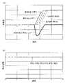
図2(a)、(b)は、車両0、車両1、車両2、車両3がそれぞれ図1に示したようなカーブ路を走行する際に、従来手法1、すなわち各車両独自にG-Vectoring制御を行った時の、各車両の前後加速度および横加速度、並びに各車両間の車間距離(車両1-車両0、車両2-車両1、車両3-車両2)を示している。 FIGS. 2(a) and 2(b) show
この場合、図2(a)に示すように、車両0、車両1、車両2、車両3それぞれにおいて、走行軌跡の曲率(≒道路曲率)が増加し、横加速度(の絶対値)が増加する区間において、横運動に連係した前後加速度制御(G-Vectoring制御)を行っていることがわかる。この時、先頭車両である車両0から順に負の前後加速度制御を行うこととなるため、図2(b)に示すように、各車両間の車間距離は順次小さな値となっている。 In this case, as shown in FIG. 2(a), the curvature of the trajectory of
また、図3にこの時の前後加速度と横加速度の関係である“g-g”ダイアグラムを示す。両者の関係を見てみると、全車両で同じ変化となっており、すべての車両において前後加速度から横加速度へスムーズに遷移する運動を実現している。 Also, FIG. 3 shows a "gg" diagram showing the relationship between the longitudinal acceleration and the lateral acceleration at this time. Looking at the relationship between the two, the change is the same for all vehicles, and all vehicles achieve motion that smoothly transitions from longitudinal acceleration to lateral acceleration.
しかし、図2(b)に示したように、各車両が独自にG-Vectoring制御を行う構成では、カーブ進入時に車間距離が減少するため、隊列走行する車両間での衝突の危険性が高まり、また、それを避けるためには隊列走行時の車間距離を大きくとる必要がある。この場合、隊列走行による輸送密度向上といった効果が小さくなり、各車両が単独で走行するシーンと変わらないものとなってしまう。 However, as shown in Figure 2(b), in a configuration in which each vehicle performs its own G-Vectoring control, the distance between vehicles decreases when entering a curve, increasing the risk of collisions between vehicles traveling in platoons. Also, in order to avoid this, it is necessary to secure a large inter-vehicle distance during platooning. In this case, the effect of improving the transportation density by platooning becomes small, and the scene is the same as that in which each vehicle runs alone.
図4(a)、(b)は、車両0、車両1、車両2、車両3がそれぞれ図1に示したようなカーブ路を走行する際に、従来手法2、すなわち隊列内の車両が同じ速度プロファイルにて前後加速度制御を行った時の、各車両の前後加速度および横加速度、並びに各車両間の車間距離(車両1-車両0、車両2-車両1、車両3-車両2)を示している。 4(a) and 4(b) show
この場合、図4(a)に示すように、車両0、車両1、車両2、車両3の全てにおいて、車両0の走行軌跡の曲率(≒道路曲率)が増加し、車両0の横加速度(の絶対値)が増加するタイミングで開始するG-Vectoring制御と同一の前後加速度制御が行われていることがわかる。この時、全車両同時に同じ負の前後加速度制御を行うこととなるため、図4(b)に示すように、各車両間の車間距離は変化することなく、前後加速度制御前の車間距離を維持できている。 In this case, as shown in FIG. 4(a), in all of
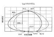
また、図5にこの時の前後加速度と横加速度の関係である“g-g”ダイアグラムを示す。両者の関係を見てみると、車両0では前後加速度から横加速度へスムーズに遷移する運動を実現しているものの、後続の車両(車両1、車両2、車両3)になるほど横加速度が小さい領域で発生する負の前後加速度が大きくなり、前後加速度と横加速度が連係しない区間が増加する。 Also, FIG. 5 shows a "gg" diagram showing the relationship between the longitudinal acceleration and the lateral acceleration at this time. Looking at the relationship between the two,
本発明では、隊列走行時の車間距離を適切に保ちながら、カーブ路走行時の隊列内の全ての車両の乗り心地が好適となるよう、すべての車両で横運動に連係した前後運動となる前後加速度制御を行う手法を提案する。 In the present invention, the longitudinal movement of all vehicles is performed in conjunction with the lateral movement so that the ride comfort of all vehicles in the platoon when traveling on a curve is suitable while maintaining an appropriate inter-vehicle distance during platooning. We propose a method for controlling acceleration.
以下、図7(a)、(b)、図8(a)~(c)を用いて、本発明における前後加速度制御の特徴を説明する。図7(a)、(b)、図8(a)~(c)の説明において、図6に示すように、隊列内の複数台の車両で、先行して走行する先行車両を車両n、車両nに追従走行(車両nの後方を走行)する後続車両を車両n+1とし、両者の車間距離をdn+1としている(ここでnは0以上の整数)。 The features of longitudinal acceleration control in the present invention will be described below with reference to FIGS. 7(a), (b), and FIGS. 8(a) to (c). 7(a), (b), and FIGS. 8(a) to (c), as shown in FIG. A following vehicle following vehicle n (running behind vehicle n) is assumed to be vehicle n+1, and the inter-vehicle distance is assumed to be dn+1 (where n is an integer equal to or greater than 0).
初めに図7(a)、(b)を用いて、直進状態から定常旋回状態へと遷移する走行シーン(図1のa手前~図1のb)における前後加速度制御を説明する。図7(a)は、隊列内の車両nおよび車両nの後続車両である車両n+1の、横加速度および前後加速度の時間変化、図7(b)は、両者の車間距離dn+1の時間変化を示している。図7(a)に示す通り、車両n、車両n+1それぞれにおいて、カーブ進入(走行軌跡の曲率(≒道路曲率)が増加)、すなわち横加速度が発生する前(車両nにおいて時刻t3の前、車両n+1において時刻t4の前)から、定常旋回(走行軌跡の曲率(≒道路曲率)が一定)、すなわち横加速度が略一定となる時刻(車両nにおいて時刻t5、車両n+1において時刻t6)まで、連続的に負の前後加速度を発生(つまり、減速)していることがわかる。ここで、本発明において、後続の車両である車両n+1は、その横加速度の絶対値が増加、すなわち旋回を開始する前に減速を開始し、減速を開始する時刻t1での前後加速度が、同時刻における車両nに発生する前後加速度よりも小さい。すなわち、同時刻で後続車両である車両n+1に発生する減速度が先行車両である車両nに発生する減速度よりも大きくなるよう、前後加速度制御を行うことを特徴とする。 First, referring to FIGS. 7(a) and 7(b), longitudinal acceleration control in a driving scene (before a in FIG. 1 to b in FIG. 1) in which the vehicle transitions from a straight running state to a steady turning state will be described. FIG. 7(a) shows temporal changes in lateral acceleration and longitudinal acceleration of vehicle n in the platoon and vehicle n+1, which is the vehicle following vehicle n, and FIG. 7(b) shows temporal changes in inter-vehicle
より詳細には、後で説明するように、後続の車両である車両n+1は、車両nの走行情報を取得可能であり、車両nの横加速度の絶対値が増加、すなわち車両nの走行軌跡の曲率(≒道路曲率)が増加して旋回を開始する時刻t3よりも前の時刻t1に、負の前後加速度を発生させて減速を開始する。また、図7(a)に示す例では、時刻t1よりも後かつ時刻t3よりも前の時刻t2に、車両nも、その横加速度の絶対値が増加、すなわち旋回を開始する前に負の前後加速度を発生させて減速を開始するが、時刻t3における車両nの速度より、同時刻(時刻t3)における車両n+1の速度が小さくなるよう、時刻t1から時刻t3の間に、車両nおよび車両n+1に負の前後加速度を発生させて減速する。 More specifically, as will be described later, vehicle n+1, which is the following vehicle, can acquire the traveling information of vehicle n, and the absolute value of the lateral acceleration of vehicle n increases, that is, the traveling trajectory of vehicle n increases. At time t1 before time t3 at which the curvature (≈road curvature) increases and turning is started, negative longitudinal acceleration is generated to start deceleration. In the example shown in FIG. 7A, at time t2, which is after time t1 and before time t3, the absolute value of the lateral acceleration of vehicle n increases, that is, the vehicle n becomes negative before it starts turning. A longitudinal acceleration is generated to start deceleration, but between time t1 and time t3, vehicle n and vehicle A negative longitudinal acceleration is generated at n+1 to decelerate.
これにより、図7(b)に示すように、両者の車間距離dn+1を増加させる。 As a result, the inter-vehicle distance dn+1 between the two is increased as shown in FIG. 7(b).
その後、先行する車両nがカーブに進入する時刻t3から、走行軌跡の曲率が増加して横加速度の絶対値が増加し、走行軌跡の曲率が一定になって定常旋回に至る時刻t5の区間において、車両nは、例えばG-Vectoring制御のような横運動に連係した前後運動となるような前後加速度制御を行う。更に、後続する車両n+1においても、カーブに進入する時刻t4から、走行軌跡の曲率が増加して横加速度の絶対値が増加し、走行軌跡の曲率が一定になって定常旋回に至る時刻t6の区間において、例えばG-Vectoring制御のような横運動に連係した前後運動となるような前後加速度制御を行う。この時に車両nに発生する減速度が、車両n+1に発生している減速度よりも大きければ(例えば、図7(a)に示すように、時刻t3から時刻t5の区間に発生する車両nの前後加速度の最小値よりも、時刻t4から時刻t6の区間に発生する車両n+1の前後加速度の最小値が大きくなるように制御すれば)、両者の車間距離dn+1は減少し始める。ここでは、車両nの横加速度の絶対値が増加、かつ、車両n+1の横加速度の絶対値が増加する区間(時刻t4から時刻t5の区間)において、両者の車間距離dn+1が減少するよう、車両nおよび/または車両n+1の(負の)前後加速度が制御されている。 After that, from time t3 when the preceding vehicle n enters the curve, the curvature of the trajectory increases, the absolute value of the lateral acceleration increases, the curvature of the trajectory becomes constant, and a steady turn is reached at time t5. , the vehicle n performs longitudinal acceleration control, such as G-Vectoring control, for longitudinal motion linked to lateral motion. Furthermore, in the following vehicle n+1 as well, from time t4 when the vehicle enters the curve, the curvature of the trajectory increases, the absolute value of the lateral acceleration increases, the curvature of the trajectory becomes constant, and at time t6 when the vehicle makes a steady turn. In the section, for example, longitudinal acceleration control such as G-Vectoring control is performed so as to achieve longitudinal motion linked to lateral motion. If the deceleration occurring in vehicle n at this time is greater than the deceleration occurring in vehicle n+1 (for example, as shown in FIG. If control is performed so that the minimum value of longitudinal acceleration of vehicle n+1 occurring in the interval from time t4 to time t6 is greater than the minimum value of longitudinal acceleration, the inter-vehicle distance dn+1 between the two begins to decrease. Here, in the section (the section from time t4 to time t5) in which the absolute value of the lateral acceleration of vehicle n increases and the absolute value of the lateral acceleration of vehicle n+1 increases, the inter-vehicle distance dn+1 between the two decreases. , the (negative) longitudinal acceleration of vehicle n and/or vehicle n+1 is controlled.
ここで、カーブに対する前後加速度制御開始前、すなわち車両n+1の減速開始時刻t1より前の時刻において、両者の速度が同じである時、車両nの時刻t2から時刻t5までの前後加速度の積分値と、車両n+1の時刻t1から時刻t6までの積分値が同じであれば、両者の定常旋回時の速度は同速度となり、同じ横加速度での旋回となる。更に、両者の相対速度ΔVn+1の時刻t1から時刻t6の間の積分値がゼロとなるように両者の前後加速度制御を行うことで、車両n+1が定常旋回を開始する時刻t6で、両者の車間距離dn+1は、時刻t1以前の車間距離と同距離にすることができる。 Here, before the start of the longitudinal acceleration control for the curve, that is, at the time before the deceleration start time t1 of the vehicle n+1, when both the speeds are the same, the integrated value of the longitudinal acceleration of the vehicle n from the time t2 to the time t5 is , the vehicle n+1 has the same integral value from the time t1 to the time t6, the vehicle n+1 has the same speed during steady turning, and turns with the same lateral acceleration. Furthermore, by performing longitudinal acceleration control of both so that the integrated value of the relative speed ΔVn+1 between the two between time t1 and time t6 becomes zero, at time t6 when the vehicle n+1 starts steady turning, The inter-vehicle distance dn+1 can be made the same as the inter-vehicle distance before time t1.
これにより、車両n、車両n+1それぞれに横運動に連係した前後運動を発生する前後加速度制御を実現しながら、例えば定常旋回時の車間距離を旋回開始前の車間距離とすることができる。 As a result, for example, the vehicle-to-vehicle distance during steady turning can be set to the vehicle-to-vehicle distance before the start of turning, while realizing longitudinal acceleration control that generates longitudinal movement linked to lateral movement in each of vehicle n and vehicle n+1.
次に図8(a)~(c)を用いて、定常旋回状態から直進状態へと遷移する走行シーン(図1のb~図1のd以降)における前後加速度制御を説明する。本走行シーンでは、横運動に連係した正の前後加速度制御に加え、車両n、および車両n+1の車間距離を目標値(目標車間距離)とする前後加速度制御、並びに、車両n、および車両n+1の速度を目標値(目標速度)とする前後加速度制御を合わせて行う。図8(a)は、隊列内の車両nおよび車両nの後続車両である車両n+1の、横加速度および前後加速度の時間変化、図8(b)は、両者の車間距離dn+1の時間変化、図8(c)は、両者の速度の時間変化を示している。図8(a)に示す通り、車両n、車両n+1それぞれにおいて、略一定の横加速度となっている定常旋回(走行軌跡の曲率(≒道路曲率)が一定)(車両nにおいて時刻t7、車両n+1において時刻t8)から、横加速度がゼロとなる時刻(車両nにおいて時刻t9、車両n+1において時刻t10)まで、連続的に正の前後加速度を発生(つまり、加速)していることがわかる。また、どちらの車両も、その走行軌跡の曲率が減少してその横加速度の絶対値が減少し始める時刻t7(車両n)、t8(車両n+1)から、発生する正の前後加速度を増加させ、その後、図8(c)に示す速度が目標速度に近づくにつれて、正の前後加速度を減少させる。 Next, referring to FIGS. 8(a) to 8(c), longitudinal acceleration control in a running scene (from b to d in FIG. 1) in which the vehicle transitions from a steady turning state to a straight running state will be described. In this driving scene, in addition to positive longitudinal acceleration control linked to lateral motion, longitudinal acceleration control with the inter-vehicle distance of vehicle n and vehicle n+1 as a target value (target inter-vehicle distance), and control of vehicle n and vehicle n+1. Longitudinal acceleration control with the speed as a target value (target speed) is also performed. FIG. 8(a) shows temporal changes in lateral acceleration and longitudinal acceleration of vehicle n in the platoon and vehicle n+1, which is the vehicle following vehicle n, and FIG. 8(b) shows temporal changes in inter-vehicle
この時の車両nおよび車両n+1の前後加速度を比較すると、正の前後加速度が発生する時刻は、先行する車両n(時刻t7)の方が、後続する車両n+1(時刻t8)よりも早い。つまり、後で説明するように、先行する車両nは、後続する車両n+1の走行情報を取得可能であり、後続する車両n+1の走行軌跡の曲率が減少して横加速度の絶対値が減少し始める時刻t8よりも前の時刻t7に、当該車両nに正の前後加速度を発生させる。また、時刻t8における車両nの速度より、同時刻(時刻t8)における車両n+1の速度が小さくなるよう、時刻t7から時刻t8の間に、車両nおよび車両n+1に正の前後加速度を発生させて加速する。なお、図8(a)に示す例では、この区間の車両n+1の前後加速度がゼロであるが、必ずしもゼロである必要は無い。また、後続する車両n+1が目標速度へ到達し、その前後加速度がゼロとなる時刻t11は、先行する車両nが目標車速に到達し、その前後加速度がゼロとなる時刻t12よりも早い。また、旋回過渡期(走行軌跡の曲率が一定の定常旋回状態から走行軌跡の曲率が減少して横加速度の絶対値がゼロとなる直進状態)(車両nにおいて時刻t7から時刻t9、車両n+1において時刻t8から時刻t10)に発生する前後加速度の最大値は、後続車両である車両n+1の方が先行車両である車両nよりも大きくなるように(図8(a)の時刻t9付近参照)、両者の(正の)前後加速度制御を行う。また、ここでは、後続車両である車両n+1の走行軌跡の曲率が減少して横加速度の絶対値が減少し、その横加速度の絶対値(もしくは走行軌跡の曲率)が直進走行とみなせる値(ここでは、約ゼロであって予め設定された値)以下となる時刻t10において、車両n+1の速度が車両nの速度よりも大きくなるよう、車両n+1および/または車両nの(正の)前後加速度が制御されている(図8(c)参照)。 Comparing the longitudinal accelerations of vehicle n and vehicle n+1 at this time, the time at which positive longitudinal acceleration occurs is earlier in preceding vehicle n (time t7) than in following vehicle n+1 (time t8). In other words, as will be explained later, the leading vehicle n can obtain the travel information of the following vehicle n+1, the curvature of the trail of the following vehicle n+1 decreases, and the absolute value of the lateral acceleration starts to decrease. At time t7, which is earlier than time t8, the vehicle n is caused to generate positive longitudinal acceleration. Further, between time t7 and time t8, vehicle n and vehicle n+1 are caused to generate positive longitudinal acceleration so that the speed of vehicle n+1 at time t8 is smaller than the speed of vehicle n at time t8. To accelerate. In the example shown in FIG. 8A, the longitudinal acceleration of the vehicle n+1 in this section is zero, but it does not necessarily have to be zero. Time t11 at which the following vehicle n+1 reaches the target speed and its longitudinal acceleration becomes zero is earlier than time t12 at which the preceding vehicle n reaches the target vehicle speed and its longitudinal acceleration becomes zero. Also, the turning transition period (from the steady turning state in which the curvature of the traveling locus is constant to the straight running state in which the curvature of the traveling locus decreases and the absolute value of the lateral acceleration becomes zero) (from time t7 to time t9 for vehicle n, The maximum value of the longitudinal acceleration occurring from time t8 to time t10 is such that the vehicle n+1, which is the following vehicle, is larger than the vehicle n, which is the preceding vehicle (see time t9 in FIG. 8A). Both (positive) longitudinal acceleration control is performed. Here, the curvature of the trajectory of the vehicle n+1, which is the following vehicle, decreases, the absolute value of the lateral acceleration decreases, and the absolute value of the lateral acceleration (or the curvature of the trajectory of the vehicle) becomes a value (here, Then, at time t10, when the speed of vehicle n+1 is approximately zero and equal to or less than a preset value, the (positive) longitudinal acceleration of vehicle n+1 and/or vehicle n is adjusted so that the speed of vehicle n+1 becomes greater than the speed of vehicle n. controlled (see FIG. 8(c)).
これにより、図8(b)に示すように、両者の車間距離dn+1を最初に増加させ(図8(b)に示す例では、時刻t9と時刻t10の途中まで増加)、その後、後続車両n+1の加速に応じて両者の車間距離dn+1が減少する。 As a result, as shown in FIG. 8B, the inter-vehicle distance dn+1 between the two is first increased (in the example shown in FIG. The inter-vehicle distance dn+1 between the two decreases as the vehicle n+1 accelerates.
ここで、車両nの時刻t7から時刻t12までの前後加速度の積分値、および車両n+1の時刻t8から時刻t11までの積分値は、それぞれ正の前後加速度制御開始前の速度と目標速度の差分となるよう設定し、更に両者の相対速度ΔVn+1の時刻t7から時刻t12の間の積分値と時刻t7における車間距離の和が(カーブ後の)直進走行時の目標車間距離となるよう前後加速度制御を行うことで、車両n、および車両n+1がそれぞれカーブに対する前後加速度制御が終了した際に、目標とする車間距離での走行を継続することができる。 Here, the integrated value of the longitudinal acceleration of vehicle n from time t7 to time t12 and the integrated value of vehicle n+1 from time t8 to time t11 are each the difference between the speed before starting the positive longitudinal acceleration control and the target speed. Further, the longitudinal acceleration is set so that the sum of the integrated value of the relative velocity ΔVn+1 between time t7 and time t12 and the inter-vehicle distance at time t7 becomes the target inter-vehicle distance when traveling straight ahead (after the curve). This control allows vehicle n and vehicle n+1 to continue running at the target inter-vehicle distance when the longitudinal acceleration control for the curve ends.
このように、定常旋回から直進走行へと遷移する際の、横運動に連係した正の前後加速度制御に、車両n、および車両n+1の車間距離を目標値とする前後加速度制御、並びに、車両n、および車両n+1の速度を目標値とする前後加速度制御を考慮することで、それぞれ個別に前後加速度制御を行う場合よりも、前後加速度の増減回数を減少することができ、乗員の乗り心地向上が期待できる。 In this way, the positive longitudinal acceleration control linked to the lateral motion at the time of transition from steady turning to straight running is combined with longitudinal acceleration control in which the inter-vehicle distance between vehicle n and vehicle n+1 is set as a target value, and vehicle n. , and the speed of vehicle n+1 as a target value, the number of changes in longitudinal acceleration can be reduced compared to the case where longitudinal acceleration control is performed individually, and the ride comfort of the occupant can be improved. I can expect it.
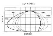
図9に、図7(a)、(b)、図8(a)~(c)に示した本発明の前後加速度制御を行った際の前後加速度と横加速度の関係である“g-g”ダイアグラムを示す。この図9から、先行する車両nと後続の車両n+1の両者とも、原点から左回りの円を描くように前後加速度と横加速度の関係が遷移しており、車両n、車両n+1のどちらの車両に対しても、横運動と前後運動が連係した乗り心地が好適となる加速度変化を提供することができている。 FIG. 9 shows the relationship between the longitudinal acceleration and the lateral acceleration when the longitudinal acceleration control of the present invention shown in FIGS. 7(a), (b), and FIGS. "Show the diagram. From FIG. 9, both the preceding vehicle n and the following vehicle n+1 have transitions in the relationship between the longitudinal acceleration and the lateral acceleration so as to draw a counterclockwise circle from the origin. Also, it is possible to provide an acceleration change that makes the ride comfort that the lateral movement and the longitudinal movement are linked to each other.
前記した本発明の効果を確認するため、図10(a)、(b)、図11に、図1に示した4台の隊列走行に本発明による前後加速度制御を提供した例を示す。図10(a)、(b)は、車両0、車両1、車両2、車両3の前後加速度および横加速度、並びに各車両間の車間距離(車両1-車両0、車両2-車両1、車両3-車両2)を示し、図11は、この時の車両0、車両1、車両2、車両3の前後加速度と横加速度の関係(“g-g”ダイアグラム)を示している。 In order to confirm the effect of the present invention, FIGS. 10(a), (b) and 11 show an example in which longitudinal acceleration control according to the present invention is applied to the platooning of four vehicles shown in FIG. 10(a) and (b) show the longitudinal acceleration and lateral acceleration of
図10(a)に示すように、カーブ路に進入・退出する車両0、車両1、車両2、車両3それぞれにカーブ路に対する異なる前後加速度制御が行われており、その結果、図10(b)に示すように、各車両間の車間距離(車両1-車両0、車両2-車両1、車両3-車両2)は、旋回開始前から旋回終了まで2回の増減を繰り返し(具体的には、一旦車間距離をあけた後、そのあけた分の車間距離をつめる動作を行い)、最終的に初期の車間距離d0に収束している。なお、図10(a)に示す例では、先頭車両がカーブ路に対する減速を開始するシーンで、隊列最後尾の車両から順次負の前後加速度を発生させて減速を開始しているが、後述するように、後方の車両ほど発生する前後加速度が小さく(減速度が大きく)なるように制御してもよい。また、この時の前後加速度と横加速度の関係は、図11に示すように、隊列内全ての車両(車両0、車両1、車両2、車両3)において、原点から円を描くような形状となっていることがわかる。 As shown in FIG. 10(a),
このように、本発明の前後加速度制御により、隊列走行によるカーブ路通過時においても、車間距離を所定以上に保ちながら、隊列内のすべての車両に横運動と前後運動が連係した乗り心地が好適となる加速度変化を提供することが可能となる。 As described above, the longitudinal acceleration control of the present invention ensures that all vehicles in the platoon can enjoy a comfortable ride in which the lateral and longitudinal movements are coordinated while maintaining the distance between the vehicles at a predetermined level or more even when passing through a curved road in platooning. It is possible to provide an acceleration change that becomes
なお、隊列走行時におけるカーブ路通過時の前後加速度制御方法は、ここに示した方法に限定するものではなく、隊列内を先行して走行する車両nと前記車両nに後続する車両n+1の車間距離dn+1が、前記車両n+1の横加速度の絶対値、もしくは走行軌跡(道路軌跡上で車両n+1が走行すべき軌跡)の曲率(≒道路曲率)が増加する前に、両者の車間距離が増加するように、車両n+1、もしくは車両nと車両n+1の両方の前後加速度を制御し、前記車両n+1の横加速度の絶対値、もしくは走行軌跡の曲率が増加し始める際に(つまり、前記車両nおよび前記車両n+1の横加速度の絶対値、もしくは走行軌跡の曲率が増加する区間以降で)、車両n+1の速度が車両nの速度よりも小さくなるよう、車両nおよび車両n+1の前後加速度を制御する方法であればよい。また、隊列内を先行して走行する車両nと後続の車両n+1の車間距離dn+1が、後続の前記車両n+1の横加速度の絶対値、もしくは走行軌跡の曲率(≒道路曲率)が減少する前に、両者の車間距離が増加するように、車両n、もしくは車両nと車両n+1の両方の前後加速度を制御し、前記車両n+1の横加速度の絶対値、もしくは走行軌跡の曲率が減少し始める際に(つまり、前記車両および前記車両n+1の横加速度の絶対値、もしくは走行軌跡の曲率が減少する区間以降で)、車両n+1の速度が車両nの速度よりも小さくなるよう、車両nおよび車両n+1の前後加速度を制御する方法であればよい。前記図7(a)に示した以外の方法として、例えば図7(a)における時刻t1および時刻t2を同じタイミングとし、車両n+1に発生させる負の前後加速度を、車両nに発生させる負の前後加速度よりも小さな値(大きな減速度)とすることで、後続の車両n+1の横加速度の絶対値が増加する前に両者の車間距離dn+1を大きくする方法であってもよい。また、前記図8(a)に示した以外の方法として、例えば図8(a)において、時刻t7よりも早いタイミングで、車両nに、車両n+1(ここでの前後加速度はゼロでなくてもよい)よりも大きな前後加速度を発生させることで、車両n+1の横加速度の絶対値が減少する前に両者の車間距離dn+1を大きくする方法であってもよい。 It should be noted that the longitudinal acceleration control method when passing through a curved road during platooning is not limited to the method shown here. Before the distance dn+1 increases the absolute value of the lateral acceleration of the vehicle n+1 or the curvature of the travel trajectory (the trajectory on which the vehicle n+1 should travel on the road) (≒ road curvature), the inter-vehicle distance between the two increases The longitudinal acceleration of vehicle n+1, or both vehicle n and vehicle n+1, is controlled to increase, and when the absolute value of the lateral acceleration of said vehicle n+1 or the curvature of the trajectory begins to increase (i.e., said vehicle n and the longitudinal acceleration of the vehicle n and the vehicle n+1 is controlled so that the speed of the vehicle n+1 becomes lower than the speed of the vehicle n after the section where the absolute value of the lateral acceleration of the vehicle n+1 or the curvature of the travel locus increases. Any method is acceptable. In addition, the inter-vehicle distance dn+1 between the preceding vehicle n and the following vehicle n+1 in the platoon decreases, and the absolute value of the lateral acceleration of the following vehicle n+1 or the curvature of the travel path (≒road curvature) decreases. control the longitudinal acceleration of vehicle n or both vehicle n and vehicle n+1 so that the inter-vehicle distance between the two increases, and the absolute value of the lateral acceleration of vehicle n+1 or the curvature of the running trajectory begins to decrease. (i.e. after the section where the absolute values of the lateral accelerations of the vehicle and the vehicle n+1 or the curvature of the travel locus decreases), the vehicle n and the vehicle Any method may be used as long as it controls the n+1 longitudinal acceleration. As a method other than that shown in FIG. 7A, for example, the time t1 and the time t2 in FIG. A value smaller than the acceleration (larger deceleration) may be used to increase the inter-vehicle distance dn+1 between the following vehicle n+1 before the absolute value of the lateral acceleration of the following vehicle n+1 increases. As a method other than that shown in FIG. 8A, for example, in FIG. good) to increase the vehicle-to-vehicle distance dn+1 before the absolute value of the lateral acceleration of the vehicle n+1 decreases.
[第1実施形態]
以下、図12~図15を用いて、本発明の第1実施形態による車両運動制御装置の構成及び動作について説明する。本第1実施形態は、前述した本発明の前後加速度制御を実行可能な車両運動制御装置が、隊列内の車両(後続車両、先行車両、またはその両者)に搭載され、該車両運動制御装置が搭載された車両(以下、自車両ということがある)外の車両(以下、他車両ということがある)の走行情報を取得して、自車両の加速度(前後加速度、横加速度)を自動的に制御するものである。[First embodiment]
The configuration and operation of the vehicle motion control system according to the first embodiment of the present invention will be described below with reference to FIGS. 12 to 15. FIG. In the first embodiment, the vehicle motion control device capable of executing the longitudinal acceleration control of the present invention described above is mounted on a vehicle (following vehicle, leading vehicle, or both) in a platoon, and the vehicle motion control device is Acquire the driving information of the vehicle (hereinafter sometimes referred to as the other vehicle) outside the mounted vehicle (hereinafter sometimes referred to as the own vehicle) and automatically calculate the acceleration (longitudinal acceleration, lateral acceleration) of the own vehicle control.
最初に、図12、図13を用いて、本発明の第1実施形態による車両運動制御装置を搭載した車両および当該車両運動制御装置の構成について説明する。 First, a vehicle equipped with a vehicle motion control system according to the first embodiment of the present invention and the configuration of the vehicle motion control system will be described with reference to FIGS. 12 and 13. FIG.
図12は、本発明の第1実施形態による車両運動制御装置を搭載した車両の構成図を示したものである。 FIG. 12 shows a configuration diagram of a vehicle equipped with the vehicle motion control system according to the first embodiment of the invention.
本実施形態の車両運動制御装置1は車両21に搭載されるものであり、車両運動状態情報を取得するセンサ(加速度センサ2、ジャイロセンサ3、車輪速センサ8)、ドライバ操作情報を取得するセンサ(操舵角センサ5、ブレーキペダルセンサ17、アクセルペダルセンサ18)、自車両走行路情報を取得するセンサ(コース形状取得センサ6、自車両位置検出センサ9、外界情報検出センサ19)、自車両外の制御機器と通信することで情報の送受信を行う車外通信ユニット20などから得られる各種情報に基づいて、加速度制御に必要な演算を行い、その演算結果に基づいて、車両に発生する前後加速度および/もしくは横加速度を制御可能なアクチュエータ(ブレーキアクチュエータ11、駆動アクチュエータ13、舵角制御アクチュエータ16)の駆動制御を行う各制御ユニット(ブレーキ制御ユニット10、駆動トルク制御ユニット12、舵角制御ユニット15)に通信ライン14を通じて制御指令値を送信する。 The vehicle
ここで、前記車両運動状態情報を取得するセンサとして、車両速度、前後加速度、横加速度、ヨーレイトを取得できるセンサ、もしくは手段であればよく、上記センサ構成に限定するものではない。例えばグローバルポジショニングシステム(GPS)により得られる位置情報を微分することで、車両速度を取得してもよい。また、カメラのような画像取得センサを用いて車両のヨーレイト、前後加速度、横加速度を取得してもよい。また、前記車両運動制御装置1が直接センサの入力を持たなくともよい。例えば別な制御ユニット(例えばブレーキ制御ユニット10)から通信ライン14を通じて必要な情報を取得してもよい。 Here, the sensor that acquires the vehicle motion state information may be any sensor or means capable of acquiring vehicle speed, longitudinal acceleration, lateral acceleration, and yaw rate, and is not limited to the sensor configuration described above. For example, vehicle speed may be obtained by differentiating position information obtained by a global positioning system (GPS). Also, the yaw rate, longitudinal acceleration, and lateral acceleration of the vehicle may be acquired using an image acquisition sensor such as a camera. Further, the vehicle
ドライバ操作情報を取得するセンサとして、ドライバによるステアリングホイール4の操作量、図示していないブレーキペダルおよびアクセルペダルの操作量を取得できればよく、上述の車両運動状態情報の取得同様、前記車両運動制御装置1が直接センサの入力を持たなくともよい。例えば別な制御ユニット(例えばブレーキ制御ユニット10)から通信ライン14を通じて必要な情報を取得してもよい。 As a sensor for acquiring driver operation information, it is sufficient that the amount of operation of the
自車両走行路情報を取得するセンサとして、グローバルポジショニングシステム(GPS)を自車両位置検出センサ9として用い、外界情報検出センサ19として、カメラやレーダ等、自車両周辺の障害物を検出して走行可能な領域を検出可能なセンサを用い、コース形状取得センサ6として、ナビゲーションシステムのような自車両の走行経路情報を取得できるものを利用できる。ここで、自車両走行路情報を取得するセンサとして、自車両の進行方向におけるコース形状(道路形状ともいう)および外界情報(走行可能領域)が取得できる手段であればよく、これらセンサに限定するものではない。例えばデータセンタや路上に設置された道路情報を送信する機器との通信により自車両前方のコース形状を取得する方法であってもよいし、カメラのような撮像手段により自車両前方もしくは周囲、またはその両方の画像を取得し、自車両前方のコース形状を取得する方法であってもよい。また、これら手段のいずれか、もしくはその組み合わせにより、自車両進行方向のコース形状を演算するユニットから通信ライン14を通じて取得する方法であってもよい。 A global positioning system (GPS) is used as the vehicle position detection sensor 9 as a sensor for acquiring the own vehicle travel path information, and the external
車外通信ユニット20は、無線もしくは有線による通信により、車両外に設置されている制御装置との通信により信号の送受信を行うものであり、通信方法としては、セルラー回線もしくWiFi(登録商標)等の無線通信手段による通信方法であっても、他車両もしくは路面側インフラシステムと電信ケーブルを介した直接接触による通信方法であってもよい。この車外通信ユニット20を介して、車両運動制御装置1は、隊列内を走行する自車両外の他車両の走行情報(他車両情報)を取得(受信)し、当該自車両の走行情報(自車両情報)を他車両に出力(送信)する。ここで、走行情報(他車両情報、自車両情報)には、走行軌跡、速度、前後加速度制御計画、車間距離などが含まれる。また、車両運動制御装置1は、この車外通信ユニット20によるデータセンタとの通信により、車両21が走行する路面の過去の走行データ軌跡を取得してもよい。なお、他車両情報は、前記車外通信ユニット20を用いず、車両21に搭載されている前記外界情報検出センサ19としてのカメラやレーダ等を用いて取得してもよい。 The vehicle
前記車両21に発生する前後加速度を制御可能な加減速アクチュエータ(ブレーキアクチュエータ11、駆動アクチュエータ13)は、タイヤ7と路面間に発生する力を制御することで当該車両21に発生する前後加速度を制御可能なアクチュエータであり、例えば、燃焼状態を制御することでタイヤ7にかかる制駆動トルクを制御し、車両21の前後加速度を制御可能な燃焼エンジン、もしくは電流を制御することでタイヤ7にかかる制駆動トルクを制御し、車両21の前後加速度を制御可能な電動モータ、もしくは動力を各車輪に伝達する際の変速比を変えることで車両21の前後加速度を制御可能な変速機、もしくは各車輪のブレーキパッドにブレーキディスクを押しつけることで車両21に前後加速度を発生させる摩擦ブレーキといった、前後加速度を制御可能な加減速アクチュエータを適用することができる。 The acceleration/deceleration actuator (
また、車両運動制御装置1は、記憶領域、演算処理能力、および信号の入出力手段等を有する演算装置を備えており、前記車両運動状態情報、前記ドライバ操作情報、前記自車両走行路情報などにより得られた各種情報から車両21に発生させる前後加速度指令値を演算し、前記前後加速度指令値となる前後加速度を発生し得る前記加減速アクチュエータを前後加速度発生手段として、前記加減速アクチュエータ(ブレーキアクチュエータ11、駆動アクチュエータ13)の駆動制御器(ブレーキ制御ユニット10、駆動トルク制御ユニット12)へ前記前後加速度指令値を送る。また、前記車両運動状態情報、前記ドライバ操作情報、前記自車両走行路情報などにより得られた各種情報から車両21に発生させる横運動指令値を演算し、前記横運動を発生し得る舵角制御アクチュエータ16を旋回運動発生手段として、前記舵角制御アクチュエータ16の駆動制御器(舵角制御ユニット15)へ前記横運動指令値としての舵角指令値を送る。 Further, the vehicle
ここで、車両運動制御装置1から送る信号は前後加速度そのものではなく、前記加減速アクチュエータによって前記前後加速度指令値を実現し得る信号であればよい。同様に、車両運動制御装置1から送る信号は舵角そのものではなく、前記舵角制御アクチュエータ16により、舵角指令値を実現し得る信号であればよい。 Here, the signal sent from the vehicle
例えば、前記加減速アクチュエータが燃焼エンジンである場合、前記前後加速度指令値を実現し得る制駆動トルク指令値を駆動トルク制御ユニット12へ送る。また、駆動トルク制御ユニット12を介さず、前後加速度指令値を実現する燃焼エンジンの駆動信号を、燃焼エンジンの制御アクチュエータに直接送ってもよい。また、油圧によりブレーキパッドをブレーキディスクに押し付ける油圧式摩擦ブレーキを用いる場合、前後加速度指令値を実現する油圧指令値をブレーキ制御ユニット10へ送る。また、ブレーキ制御ユニット10を介さず、前後加速度指令値を実現する油圧式摩擦ブレーキ駆動アクチュエータの駆動信号を油圧式摩擦ブレーキ駆動アクチュエータに直接送ってもよい。 For example, if the acceleration/deceleration actuator is a combustion engine, it sends to the driving torque control unit 12 a braking/driving torque command value that can realize the longitudinal acceleration command value. Alternatively, the drive signal for the combustion engine that realizes the longitudinal acceleration command value may be sent directly to the control actuator of the combustion engine without going through the drive
また、前後加速度指令値を実現する際に、前後加速度指令値に応じて駆動制御を行う前記加減速アクチュエータを変更してもよい。 Further, when realizing the longitudinal acceleration command value, the acceleration/deceleration actuator that performs drive control according to the longitudinal acceleration command value may be changed.
例えば、前記燃焼エンジンと油圧式摩擦ブレーキを前記加減速アクチュエータとして持つ場合、前記前後加速度指令値が前記燃焼エンジンの制駆動トルク制御により実現できる範囲であれば、前記燃焼エンジンを駆動制御し、前記前後加速度指令値が前記燃焼エンジンの制駆動トルク制御で実現できない範囲の負の値である場合、前記燃焼エンジンと合わせて油圧式摩擦ブレーキを駆動制御する。また、前記電動モータと前記燃焼エンジンを前記加減速アクチュエータとして持つ場合、前記前後加速度の時間変化が大きい場合は前記電動モータを駆動制御し、前記前後加速度の時間変化が小さい場合は前記燃焼エンジンを駆動制御するようにしてもよい。また、通常時は前記前後加速度指令値を電動モータにより駆動制御し、バッテリーの状態等により電動モータにより前後加速度指令を実現できない場合、他の加減速アクチュエータ(燃焼エンジン、油圧式摩擦ブレーキ等)を駆動制御するようにしてもよい。 For example, when the combustion engine and the hydraulic friction brake are used as the acceleration/deceleration actuator, if the longitudinal acceleration command value is within a range that can be realized by braking/driving torque control of the combustion engine, the combustion engine is driven and controlled, When the longitudinal acceleration command value is a negative value in a range that cannot be realized by the braking/driving torque control of the combustion engine, the hydraulic friction brake is driven and controlled together with the combustion engine. Further, when the electric motor and the combustion engine are used as the acceleration/deceleration actuator, the electric motor is driven and controlled when the change in the longitudinal acceleration with time is large, and the combustion engine is operated when the change in the longitudinal acceleration with time is small. You may make it drive-control. Normally, the longitudinal acceleration command value is driven and controlled by the electric motor, and when the longitudinal acceleration command cannot be realized by the electric motor due to the state of the battery, other acceleration/deceleration actuators (combustion engine, hydraulic friction brake, etc.) are used. You may make it drive-control.
また、通信ライン14として、信号によって異なる通信ラインおよび通信プロトコルを用いてもよい。例えば大容量のデータをやり取りする必要のある自車両走行路情報を取得するセンサとの通信にイーサネットを用い、各アクチュエータとの通信にはCAN(Controller Area Network)を用いる構成であってもよい。 Also, as the
図13は、本発明の第1実施形態による車両運動制御装置1の構成図を示したものである。以下では、主に、前述した車両運動制御装置1がカーブ路走行時のコース形状(道路形状)などに応じて自車両(車両21)の加速度(前後加速度、横加速度)を自動的に制御するための構成について説明する。 FIG. 13 shows a block diagram of the vehicle
図示するように、車両運動制御装置1は、目標軌道取得部1a、車両運動状態取得部1b、他車両情報取得部1c、車両運動制御演算部1d、制御指令送信部1e、および制御計画送信部1fからなる。 As shown, the vehicle
目標軌道取得部1aでは、前記自車両走行路情報(コース形状、外界情報)、および車両運動状態情報から、車両21を走行させるための目標軌道(走行軌跡)および走行可能領域を取得する。ここで、目標軌道(走行軌跡)は、コース(道路)軌跡上で自車両が走行すべき軌道であり、目標軌道の作成方法としては、自車両が走行するコース形状から目標軌道を作成する方法であってもよいし、車外通信ユニット20によるデータセンタとの通信により、自車両が走行する路面の過去の走行データ軌跡を取得し、その軌跡に基づいて作成する方法であってもよい。 The target
車両運動状態取得部1bでは、前記車両運動状態情報から、車両21の運動状態(走行速度、旋回状態、ドライバ操作量等)を取得する。 The vehicle motion
他車両情報取得部1cでは、車外通信ユニット20による通信などにより、隊列内を走行する他車両の走行情報(他車両情報)を取得する。他車両情報取得部1cは、他車両情報として、隊列内の自車両の先行車両、もしくは自車両の後続車両、もしくはその両方の、走行軌跡、速度、前後加速度制御計画、および車間距離などを取得する。ここで、他車両の速度、車間距離などについては、前記車外通信ユニット20を用いず、自車両に搭載されている前記外界情報検出センサ19を用いて取得してもよい。また、他車両情報取得部1cは、他車両情報として、前記情報に加え、隊列継続可否フラグを受け取ってもよい。 The other vehicle
車両運動制御演算部1dでは、前記目標軌道取得部1a、前記車両運動状態取得部1b、および前記他車両情報取得部1cにより得られた情報に基づいて、前記前後加速度制御を自車両搭載のアクチュエータにて実現するための前後加速度指令値、および自車両のカーブ路に対する前後加速度制御計画を演算し(後で詳述)、前記前後加速度指令値の演算結果を制御指令送信部1eに送り、前記前後加速度制御計画の演算結果を制御計画送信部1fに送る。 Based on the information obtained by the target
ここで、前後加速度に加え、横加速度も本車両運動制御装置1にて制御する場合、車両運動制御演算部1dにて、前記目標軌道取得部1a、前記車両運動状態取得部1b、および前記他車両情報取得部1cにより得られた情報に基づいて、自車両搭載のアクチュエータにて目標軌道を追従する舵角指令値を演算し、前記制御指令送信部1eに送る。 Here, when lateral acceleration is controlled by the vehicle
制御指令送信部1eでは、前記車両運動制御演算部1dにより作成された前後加速度指令値、もしくは前後加速度指令値と舵角指令値の両方に基づいて、前記前後加速度および/もしくはタイヤ実舵角を制御可能なアクチュエータ(ブレーキアクチュエータ11、駆動アクチュエータ13、舵角制御アクチュエータ16)の駆動制御を行う各制御ユニット(ブレーキ制御ユニット10、駆動トルク制御ユニット12、舵角制御ユニット15)に制御指令値を送る。 The control
一方、制御計画送信部1fでは、前記車両運動制御演算部1dにより作成された前後加速度制御計画を、前記車外通信ユニット20に送り、車外通信ユニット20により、前記前後加速度制御計画などを含む自車両の走行情報(自車両情報)を隊列内の他車両(に搭載された車両運動制御装置1)に送信する。 On the other hand, the control
図14は、第1実施形態の前記車両運動制御装置1におけるフローチャートを示したものである。 FIG. 14 shows a flow chart in the vehicle
S000では、車両運動制御装置1(の目標軌道取得部1a、車両運動状態取得部1b、他車両情報取得部1c)は、上述のように目標軌道、走行可能範囲、車速制御範囲、車両運動状態、先行車両走行軌跡、先行車両速度、先行車両前後加速度制御計画、先行車両車間距離、後続車両走行軌跡、後続車両速度、後続車両前後加速度制御計画、後続車両車間距離(必要に応じて、最大前後加速度、最小前後加速度、目標車間距離)などを取得する。ここで、目標軌道は、図15に示すように、車両重心位置を原点とし、車両速度ベクトルの方向を正としたXv軸、それと直行するYv軸を取った座標上のノード点位置データNPn(Xvn,Yvn)として変換される。nは、最も車両に近い点を0とし、自車両進行方向に向かって1、2・・・、nmaxと増加する整数である。また、nmaxは取得可能なノード点位置データ番号nの最大値である。また、NP0のYv軸成分であるYv0は、車両の横方向偏差となる。また、各ノード点はノード点位置における走行可能範囲、および車速制御範囲といった情報も合わせて持つものとする。また、車両運動制御装置1は、隊列走行において自車両が隊列最前部であり、先行車両がない場合、先行車両情報として“先行車両なし”という情報を取得し、自車両が隊列最後部であり、後続車両がない場合、後続車両情報として“後続車両なし”という情報を取得する。In S000, the vehicle motion control device 1 (the target
S100では、車両運動制御装置1(の車両運動制御演算部1d)は、先行車両前後加速度制御計画の有無を判定する。ここで、先行車両前後加速度制御計画がない場合、すなわち自車両が隊列最前部である場合、S110に進む。また、先行車両前後加速度制御計画が有る場合、S200に進む。 In S100, the vehicle motion control device 1 (vehicle motion
S110では、車両運動制御装置1(の車両運動制御演算部1d)は、前後加速度演算1として、目標軌道、走行可能範囲、車速制御範囲、車両運動状態から、前後加速度指令値および前後加速度制御計画を演算する。例えば車両速度が車速制御範囲を超えて高い場合、車両運動制御装置1(の車両運動制御演算部1d)は、車両速度が車速制御範囲に収まるよう、負の前後加速度指令値を演算する。また、目標軌道がカーブ路形状(走行路の道路曲率(≒走行軌跡の曲率)の絶対値が増加して最大値もしくは略一定に至る形状、もしくは、走行路の道路曲率(≒走行軌跡の曲率)の絶対値が最大値もしくは略一定から減少する形状)となっており、カーブ路に応じた加減速制御をおこなう場合、カーブ路形状に基づいた前後加速度指令値が演算される。例えば、車両運動制御装置1(の車両運動制御演算部1d)は、走行路の道路曲率(≒走行軌跡の曲率)の絶対値が増加し、車両に発生する横加速度の絶対値が増加する区間において負の前後加速度を発生(減速)させ、横加速度の時間変化が大きいほど、発生する前後加速度が小さくなるよう、前後加速度値を制御する(図7(a)、図10(a)参照)。また、車両運動制御装置1(の車両運動制御演算部1d)は、走行路の道路曲率(≒走行軌跡の曲率)の絶対値が減少し、車両に発生する横加速度の絶対値が減少する区間において正の前後加速度を発生(加速)させ、横加速度の時間変化が大きいほど、発生する前後加速度が大きくなるよう前後加速度値を制御する(図8(a)、図10(a)参照)。演算後、S400に進む。 In S110, the vehicle motion control device 1 (vehicle motion
S200では、車両運動制御装置1(の車両運動制御演算部1d)は、S100で判定した先行車両前後加速度制御計画にカーブ情報、すなわち、カーブ路に対する前後加速度制御計画の有無を判定する。ここで取得する前後加速度制御計画としては、現時刻から所定時刻先までの前後加速度プロファイルと前記前後加速度プロファイルにカーブ路に起因した前後加速度制御計画フラグを付記したものであってもよいし、前記ノード点位置情報と各ノード点位置での速度プロファイルもしくは前後加速度プロファイルに、カーブ路に起因して設定されたプロファイル情報に当該情報を付記したものであってもよく、先行車両のカーブ路に対する前後加速度制御計画が分かる方法であればよい。前記カーブ情報がない場合、S210に進む。また、前記カーブ情報がある場合、S300に進む。 In S200, the vehicle motion control device 1 (vehicle motion
S210では、車両運動制御装置1(の車両運動制御演算部1d)は、前後加速度演算2として、先行車両前後加速度制御計画に基づいて、自車両の前後加速度指令値および前後加速度制御計画を演算する。具体的には、車両運動制御装置1(の車両運動制御演算部1d)は、自車両と先行車両の車間距離を維持するよう、先行車両との相対速度がゼロとなる前後加速度指令値および前後加速度制御計画、もしくは自車両と先行車両の車間距離が目標車間距離となる前後加速度指令値および前後加速度制御計画を演算する。ここで、前記目標車間距離は、予め隊列内の各車両に設定される値であってもよいし、前記車外通信ユニット20により取得される値であってもよい。また、前記目標車間距離は、隊列走行の各車両に発生可能な最大前後加速度および/または最小前後加速度に応じて変更してもよい。演算後、S400に進む。 In S210, the vehicle motion control device 1 (vehicle motion
S300では、車両運動制御装置1(の車両運動制御演算部1d)は、前後加速度演算3として、先行車両前後加速度制御計画および自車両進行方向のカーブ情報に基づいて、自車両の前後加速度指令値および前後加速度制御計画を演算する。具体的には、車両運動制御装置1(の車両運動制御演算部1d)は、前述のように自車両の走行軌跡の曲率が増加または減少して自車両に発生する横加速度の絶対値が増加または減少する前に自車両と先行車両の車間距離が増加し、自車両および先行車両の走行軌跡の曲率が略一定となって自車両および先行車両の横加速度が略一定となる領域で、車間距離が(減少して)前記目標車間距離となるよう、前後加速度指令値、および、カーブ路に起因した前後加速度制御フラグを付記した前後加速度制御計画を演算する。なお、ここでの具体的な演算手法は、図6~図11に基づく説明を併せて参照されたい。演算後、S400に進む。 In S300, the vehicle motion control device 1 (vehicle motion
S400では、車両運動制御装置1(の制御指令送信部1e)は、前記前後加速度指令値に基づいて、各アクチュエータの制御指令値を演算して送信する。例えば、電動モータを用いて前後加速度を制御する場合、前記前後加速度を車両に発生させる制駆動トルク指令値を電動モータの制御コントローラに送る。また、車両運動制御装置1(の制御計画送信部1f)は、前記前後加速度制御計画を、前記車外通信ユニット20を介して後続車両に送信する。 In S400, (the control
以上で説明したように、本第1実施形態では、複数台の車両が隊列を組んで所定の車間距離を保つように走行する隊列走行において、先行車両と後続車両の車間距離が、後続車両の横加速度の絶対値、もしくは後続車両の走行軌跡の曲率が増加または減少する前に増加し、先行車両および後続車両の横加速度の絶対値、もしくは先行車両および後続車両の走行軌跡の曲率が増加または減少する区間以降で減少するよう、先行車両または後続車両の少なくとも一方の前後加速度を制御する。より詳しくは、隊列走行する車両の走行情報を車両間で送受信し、後続車両の横加速度の絶対値、もしくは後続車両の走行軌跡の曲率が増加または減少する前に、前記車間距離が増加するよう、先行車両または後続車両の少なくとも一方の前後加速度を制御し、先行車両および後続車両の横加速度の絶対値、もしくは先行車両および後続車両の走行軌跡の曲率が増加または減少する区間以降で、前記車間距離が減少するよう、先行車両および後続車両の前後加速度を制御する。 As described above, in the first embodiment, in platooning in which a plurality of vehicles form a platoon and travel so as to maintain a predetermined inter-vehicle distance, the inter-vehicle distance between the leading vehicle and the following vehicle is greater than that of the following vehicle. The absolute value of the lateral acceleration or the curvature of the trajectory of the following vehicle increases or decreases before the absolute value of the lateral acceleration of the preceding and following vehicles or the curvature of the trajectory of the preceding and following vehicles increases or The longitudinal acceleration of at least one of the preceding vehicle and the following vehicle is controlled so as to decrease after the decreasing section. More specifically, traveling information of vehicles traveling in platoon is transmitted and received between vehicles so that the inter-vehicle distance increases before the absolute value of the lateral acceleration of the following vehicle or the curvature of the traveling locus of the following vehicle increases or decreases. , the longitudinal acceleration of at least one of the preceding vehicle and the following vehicle is controlled, and after the section where the absolute value of the lateral acceleration of the preceding vehicle and the following vehicle or the curvature of the traveling trajectory of the preceding vehicle and the following vehicle increases or decreases, the distance between the vehicles Control the longitudinal acceleration of the preceding and following vehicles to reduce the distance.
換言すれば、先行車両に追従した隊列走行実行時に、先頭車両がカーブ路に対する減速を開始するシーンで、隊列最後尾の車両から負の前後加速度を発生(減速)させる、もしくは、後方の車両ほど発生する前後加速度が小さく(減速度が大きく)なるよう、各車両の前後加速度を制御する。また、車両に発生する横加速度の絶対値が増加、もしくは車両走行位置での道路曲率もしくは車両の走行軌跡の曲率が増加する区間に発生する前後加速度の最小値(最大減速度)は、先頭の車両ほど小さく(最大減速度が大きく)、車両に発生する横加速度の絶対値が減少、もしくは車両走行位置での道路曲率もしくは車両の走行軌跡の曲率が減少する区間に発生する前後加速度の最大値(最大加速度)は、後方の車両ほど大きく(最大加速度が大きく)なるよう、各車両の前後加速度を制御する。 In other words, when platooning follows the preceding vehicle, in a scene where the leading vehicle starts decelerating on a curved road, negative longitudinal acceleration is generated (decelerated) from the vehicle at the end of the platoon, or the vehicle behind the platoon is decelerated. The longitudinal acceleration of each vehicle is controlled so that the generated longitudinal acceleration is small (deceleration is large). In addition, the minimum value (maximum deceleration) of the longitudinal acceleration that occurs in the section where the absolute value of the lateral acceleration that occurs in the vehicle increases, or the curvature of the road at the vehicle traveling position or the curvature of the vehicle's traveling locus increases The maximum value of longitudinal acceleration that occurs in sections where the vehicle is smaller (maximum deceleration is larger), the absolute value of the lateral acceleration generated by the vehicle is reduced, or the curvature of the road at the vehicle's driving position or the curvature of the vehicle's driving trajectory is reduced. (maximum acceleration) controls the longitudinal acceleration of each vehicle so that the vehicle behind the vehicle has a greater maximum acceleration (maximum acceleration).
これにより、例えば直線区間を隊列走行してきた車両群が定常旋回状態に至るまでの間に発生する前後加速度と横加速度の関係を、隊列内全ての車両に対し好適に変化するよう制御することができ、各車両の乗員の快適性を向上する効果が期待できる。 As a result, for example, the relationship between the longitudinal acceleration and the lateral acceleration that occurs while a group of vehicles traveling in a row on a straight section reaches a steady turning state can be controlled so as to suitably change for all vehicles in the row. The effect of improving the comfort of passengers in each vehicle can be expected.
[第2実施形態]
次に、図16を用いて、本発明の第2実施形態による車両運動制御装置の構成及び動作について説明する。上述した第1実施形態では、車両運動制御装置1が車両21に搭載され、隊列車両内の車両21が、(車外通信ユニット20による)他車両との通信により、カーブ路を通過する際に、先行車両の前後加速度制御計画およびカーブ情報に基づいて車両21の前後加速度を制御して本発明の前後加速度制御を実現する方法を示した。一方、本第2実施形態では、車両運動制御装置1Aが、隊列車両内の各車両の走行情報を共有し、隊列車両内の各車両の前後加速度を個別に制御して本発明の前後加速度制御を実現する方法を示す。[Second embodiment]
Next, the configuration and operation of the vehicle motion control system according to the second embodiment of the present invention will be described with reference to FIG. In the above-described first embodiment, the vehicle
図16は、本発明の第2実施形態による車両運動制御装置1Aの構成図を示したものである。なお、図16に示す例では、車両運動制御装置1Aは車両21_nの外部に備えられているが、上記第1実施形態と同様、隊列走行をする車両21_n内に配備してもよい。また、車両21_nを外部から制御するコントロールセンタの制御器内に配備してもよい。 FIG. 16 shows a block diagram of a vehicle
本実施形態では、車両運動制御装置1Aは、記憶領域、演算処理能力、および信号の入出力手段等を有する演算装置を備えており、主に、隊列制御演算部1Aa、および走行制御演算部1Abを備える。 In the present embodiment, the vehicle
隊列制御演算部1Aaでは、前記コース形状、前記外界情報、前記自車両位置情報、および前記車両運動状態情報などから、n台の車両21_nから構成される隊列走行する車両群(本例では、nは正の整数)の目標軌道、目標車速、および目標車間距離を作成する。また、ここで、車両運動制御装置1Aへの入力として、隊列走行する車両群が走行するエリアの交通情報が得られる場合、前記交通情報を隊列制御演算部1Aaへ入力し、車両群の目標軌道、目標車速、および目標車間距離を作成してもよい。 The platoon control calculation unit 1Aa determines a group of vehicles traveling in a platoon consisting of n vehicles 21_n (in this example, n is a positive integer) target trajectory, target vehicle speed, and target inter-vehicle distance. If the traffic information of the area in which the platooning vehicle group travels is obtained as an input to the vehicle
走行制御演算部1Abでは、前記目標軌道、目標車速、目標車間距離、および前記車両運動状態情報などから、隊列内の車両位置に応じて各車両21_nに前後加速度を発生させる制御指令値としての前後加速度指令値を演算し、隊列走行する車両群の各車両21_nに送る。なお、走行制御演算部1Abでの、車両群の各車両21_nの走行情報を利用した各車両21_nの前後加速度の演算手法は、上述した第1実施形態と同じであるので、ここではその詳細説明は割愛する。 Based on the target trajectory, target vehicle speed, target inter-vehicle distance, vehicle motion state information, and the like, the travel control calculation unit 1Ab generates a longitudinal acceleration as a control command value for generating longitudinal acceleration in each vehicle 21_n in accordance with the vehicle position in the platoon. An acceleration command value is calculated and sent to each vehicle 21_n of the vehicle group traveling in a row. Note that the method of calculating the longitudinal acceleration of each vehicle 21_n using the travel information of each vehicle 21_n in the vehicle group in the travel control calculation unit 1Ab is the same as that of the above-described first embodiment, so a detailed description thereof will be given here. is omitted.
ここで送る制御指令値としては、前後加速度指令値そのものであっても、車両21_nに搭載されている前記加減速アクチュエータ(ブレーキアクチュエータ11、駆動アクチュエータ13)の駆動制御器(ブレーキ制御ユニット10、駆動トルク制御ユニット12)にて、前記前後加速度指令値を実現するよう演算可能な制御パラメータであってもよい。 The control command value sent here may be the longitudinal acceleration command value itself, or the drive controller (
詳しくは、走行制御演算部1Abにて行われるカーブ路に対する前後加速度制御指令値演算と同じ制御アルゴリズムを、車両21_nに搭載されている車両運動制御装置の車両運動制御演算部に備え、走行制御演算部1Abは、当該制御アルゴリズムのゲインや閾値といった制御パラメータを送ってもよい。 Specifically, the same control algorithm as the longitudinal acceleration control command value calculation for the curved road performed by the travel control calculation unit 1Ab is provided in the vehicle motion control calculation unit of the vehicle motion control device mounted on the vehicle 21_n, and the travel control calculation is performed. The part 1Ab may send control parameters such as gains and thresholds of the control algorithm.
また、隊列車両内の車両21_nの前後加速度制御範囲、すなわち前後加速度制御により発生可能な前後加速度最大値および前後加速度最小値が、車両によって異なる場合、車間距離は必ずしも全て同じである必要はなく、車両21_nとそれに後続する車両21_n+1にて制御可能な前後加速度制御範囲に応じて、車両21_nとそれに後続する車両21_n+1の目標車間距離Dtgt_n+1を変更してもよい。つまり、隊列走行の各車両21_nに発生可能な最大前後加速度および最小前後加速度、並びに車両21_nとそれに後続する車両21_n+1の目標車間距離を設定するとともに、最大前後加速度および/または最小前後加速度に応じて前記目標車間距離を変更してもよい。 Further, when the longitudinal acceleration control range of the vehicles 21_n in the platoon, that is, the longitudinal acceleration maximum value and the longitudinal acceleration minimum value that can be generated by the longitudinal acceleration control, differ from vehicle to vehicle, the inter-vehicle distances do not necessarily have to be the same. The target inter-vehicle distance Dtgt_n+1 between the vehicle 21_n and the following vehicle 21_n+1 may be changed according to the longitudinal acceleration control range that can be controlled by the vehicle 21_n and the following
具体的には、例えば車両21_nの最小前後加速度よりも、車両21_n+1の最小前後加速度が小さい場合、すなわち負の前後加速度制御可能な範囲が、車両21_nよりも21_n+1が広い場合、前記目標車間距離Dtgt_n+1を、車両21_nと車両21_nの先行車両である車両21_n-1との目標車間距離Dtgt_nよりも、大きな値とする。ここで、前記前後加速度制御可能な範囲は、車両のアクチュエータによる制約に加え、乗員の乗り心地を考慮して設定される値であり、前記前後加速度制御可能な範囲は、車両内に乗員がいない場合、車両内に乗員がいる場合よりも、大きな値としてもよい。 Specifically, for example, when the minimum longitudinal acceleration of the vehicle 21_n+1 is smaller than the minimum longitudinal acceleration of the vehicle 21_n, that is, when the negative longitudinal acceleration controllable range of the vehicle 21_n+1 is wider than that of the vehicle 21_n, the target inter-vehicle
以上で説明したように、本第2実施形態では、車両運動制御装置1Aにより、隊列走行をする各車両21_nの隊列内の車両位置に応じた前記前後加速度指令値演算を行うことで、上述の第1実施形態の図10(a)、(b)及び図11に示したのと同様の隊列走行が実現できる。 As described above, in the second embodiment, the vehicle
なお、本発明は上記した実施形態に限定されるものではなく、様々な変形形態が含まれる。例えば、上記した実施形態は本発明を分かりやすく説明するために詳細に説明したものであり、必ずしも説明した全ての構成を備えるものに限定されるものではない。また、ある実施形態の構成の一部を他の実施形態の構成に置き換えることが可能であり、また、ある実施形態の構成に他の実施形態の構成を加えることも可能である。また、各実施形態の構成の一部について、他の構成の追加・削除・置換をすることが可能である。 In addition, the present invention is not limited to the above-described embodiments, and includes various modifications. For example, the above-described embodiments have been described in detail in order to explain the present invention in an easy-to-understand manner, and are not necessarily limited to those having all the configurations described. Also, part of the configuration of one embodiment can be replaced with the configuration of another embodiment, and the configuration of another embodiment can be added to the configuration of one embodiment. Moreover, it is possible to add, delete, or replace part of the configuration of each embodiment with another configuration.
また、上記の各構成、機能、処理部、処理手段等は、それらの一部又は全部を、例えば集積回路で設計する等によりハードウェアで実現してもよい。また、上記の各構成、機能等は、プロセッサがそれぞれの機能を実現するプログラムを解釈し、実行することによりソフトウェアで実現してもよい。各機能を実現するプログラム、テーブル、ファイル等の情報は、メモリや、ハードディスク、SSD(Solid State Drive)等の記憶装置、または、ICカード、SDカード、DVD等の記録媒体に置くことができる。 Further, each of the above configurations, functions, processing units, processing means, and the like may be realized by hardware, for example, by designing a part or all of them using an integrated circuit. Moreover, each of the above configurations, functions, etc. may be realized by software by a processor interpreting and executing a program for realizing each function. Information such as programs, tables, and files that implement each function can be stored in storage devices such as memories, hard disks, SSDs (Solid State Drives), or recording media such as IC cards, SD cards, and DVDs.
また、制御線や情報線は説明上必要と考えられるものを示しており、製品上必ずしも全ての制御線や情報線を示しているとは限らない。実際には殆ど全ての構成が相互に接続されていると考えてもよい。 Further, the control lines and information lines indicate those considered necessary for explanation, and not all control lines and information lines are necessarily indicated on the product. In practice, it may be considered that almost all configurations are interconnected.
1 : 車両運動制御装置(第1実施形態)
1a: 目標軌道取得部
1b: 車両運動状態取得部
1c: 他車情報取得部
1d: 車両運動制御演算部
1e: 制御指令送信部
1f: 制御計画送信部
1A: 車両運動制御装置(第2実施形態)
1Aa: 隊列制御演算部
1Ab: 走行制御演算部
2 : 加速度センサ
3 : ジャイロセンサ
4 : ステアリングホイール
5 : 操舵角センサ
6 : コース形状取得センサ
7 : タイヤ
8 : 車輪速センサ
9 : 自車両位置検出センサ
10 : ブレーキ制御ユニット
11 : ブレーキアクチュエータ
12 : 駆動トルク制御ユニット
13 : 駆動アクチュエータ
14 : 通信ライン
15 : 舵角制御ユニット
16 : 舵角制御アクチュエータ
17 : ブレーキペダルセンサ
18 : アクセルペダルセンサ
19 : 外界情報検出センサ
20 : 車外通信ユニット
21 : 車両
21_n : 隊列走行する車両群の各車両(n:正の整数)
1: Vehicle Motion Control Device (First Embodiment)
1a: target
1Aa: platoon control calculation unit 1Ab: traveling control calculation unit 2: acceleration sensor 3: gyro sensor 4: steering wheel 5: steering angle sensor 6: course shape acquisition sensor 7: tire 8: wheel speed sensor 9: own vehicle position detection sensor 10: Brake control unit 11: Brake actuator 12: Drive torque control unit 13: Drive actuator 14: Communication line 15: Steering angle control unit 16: Steering angle control actuator 17: Brake pedal sensor 18: Accelerator pedal sensor 19: External information detection Sensor 20 : External communication unit 21 : Vehicle 21_n : Each vehicle of a group of vehicles traveling in platoon (n: positive integer)
Claims (20)
Translated fromJapanese複数台の車両による隊列走行において、先行車両と後続車両の車間距離が、後続車両の横加速度の絶対値、もしくは後続車両の走行軌跡の曲率が増加または減少する前に増加し、先行車両および後続車両の横加速度の絶対値、もしくは先行車両および後続車両の走行軌跡の曲率が増加または減少する区間以降で減少するよう、先行車両または後続車両の少なくとも一方の前後加速度を制御し、
先行車両の横加速度の絶対値、もしくは先行車両の走行軌跡の曲率が増加、かつ後続車両の横加速度の絶対値、もしくは後続車両の走行軌跡の曲率が増加する区間において、前記車間距離が減少するよう、先行車両または後続車両の少なくとも一方の前後加速度を制御することを特徴とする車両運動制御装置。A vehicle motion control device for automatically controlling longitudinal acceleration in accordance with the shape of a road in the direction of travel of the vehicle, wherein acceleration in the direction of speed increase in the direction of travel of the vehicle is positive and acceleration in the direction of speed decrease is negative,
In platooning with multiple vehicles, the inter-vehicle distance between the preceding vehicle and the following vehicle increases before the absolute value of the lateral acceleration of the following vehicle or the curvature of the trajectory of the following vehicle increases or decreases, controlling the longitudinal acceleration of at least one of the preceding vehicle and the following vehicle so that the absolute value of the lateral acceleration of the vehicle or the curvature of the trajectory of the preceding vehicle and the following vehicle decreases after the section increases or decreases;
In a section where the absolute value of the lateral acceleration of the preceding vehicle or the curvature of the trajectory of the preceding vehicle increases and the absolute value of the lateral acceleration of the following vehicle or the curvature of the trajectory of the following vehicle increases, the inter-vehicle distance decreases. A vehicle motion control device, characterizedby controlling the longitudinal acceleration of at least one of a preceding vehicle and a succeeding vehicle .
複数台の車両による隊列走行において、先行車両と後続車両の車間距離が、後続車両の横加速度の絶対値、もしくは後続車両の走行軌跡の曲率が増加または減少する前に増加し、先行車両および後続車両の横加速度の絶対値、もしくは先行車両および後続車両の走行軌跡の曲率が増加または減少する区間以降で減少するよう、先行車両または後続車両の少なくとも一方の前後加速度を制御し、
先行車両の横加速度の絶対値、もしくは先行車両の走行軌跡の曲率が減少する区間に発生する先行車両の前後加速度の最大値よりも、後続車両の横加速度の絶対値、もしくは後続車両の走行軌跡の曲率が減少する区間に発生する後続車両の前後加速度の最大値が大きいことを特徴とする車両運動制御装置。A vehicle motion control device for automatically controlling longitudinal acceleration in accordance with the shape of a road in the direction of travel of the vehicle, wherein acceleration in the direction of speed increase in the direction of travel of the vehicle is positive and acceleration in the direction of speed decrease is negative,
In platooning with multiple vehicles, the inter-vehicle distance between the preceding vehicle and the following vehicle increases before the absolute value of the lateral acceleration of the following vehicle or the curvature of the trajectory of the following vehicle increases or decreases, controlling the longitudinal acceleration of at least one of the preceding vehicle and the following vehicle so that the absolute value of the lateral acceleration of the vehicle or the curvature of the trajectory of the preceding vehicle and the following vehicle decreases after the section increases or decreases;
The absolute value of the lateral acceleration of the preceding vehicle or the maximum value of the longitudinal acceleration of the preceding vehicle occurring in the section where the curvature of the trajectory of the preceding vehicle decreases, the absolute value of the lateral acceleration of the following vehicle, or the trajectory of the following vehicle A vehicle motion control device characterized in thatthe maximum value of the longitudinal acceleration of a following vehicle generated in a section where the curvature of the road decreases is large .
複数台の車両による隊列走行において、先行車両と後続車両の車間距離が、後続車両の横加速度の絶対値、もしくは後続車両の走行軌跡の曲率が増加または減少する前に増加し、先行車両および後続車両の横加速度の絶対値、もしくは先行車両および後続車両の走行軌跡の曲率が増加または減少する区間以降で減少するよう、先行車両または後続車両の少なくとも一方の前後加速度を制御し、
後続車両の横加速度の絶対値、もしくは後続車両の走行軌跡の曲率が減少し、後続車両の横加速度の絶対値、もしくは後続車両の走行軌跡の曲率が直進走行とみなせる値以下となる時刻において、後続車両の速度が、先行車両の速度よりも大きくなるよう、先行車両または後続車両の少なくとも一方の前後加速度を制御することを特徴とする車両運動制御装置。A vehicle motion control device for automatically controlling longitudinal acceleration in accordance with the shape of a road in the direction of travel of the vehicle, wherein acceleration in the direction of speed increase in the direction of travel of the vehicle is positive and acceleration in the direction of speed decrease is negative,
In platooning with multiple vehicles, the inter-vehicle distance between the preceding vehicle and the following vehicle increases before the absolute value of the lateral acceleration of the following vehicle or the curvature of the trajectory of the following vehicle increases or decreases, controlling the longitudinal acceleration of at least one of the preceding vehicle and the following vehicle so that the absolute value of the lateral acceleration of the vehicle or the curvature of the trajectory of the preceding vehicle and the following vehicle decreases after the section increases or decreases;
At the time when the absolute value of the lateral acceleration of the following vehicle or the curvature of the trajectory of the following vehicle decreases, and the absolute value of the lateral acceleration of the following vehicle or the curvature of the trajectory of the following vehicle becomes equal to or less than the value that can be regarded as straight running, A vehicle motion control devicethat controls the longitudinal acceleration of at least one of a preceding vehicle and a following vehicle so that the speed of the following vehicle is greater than the speed of the preceding vehicle .
複数台の車両による隊列走行において、先行車両と後続車両の車間距離が、後続車両の横加速度の絶対値、もしくは後続車両の走行軌跡の曲率が増加または減少する前に増加し、先行車両および後続車両の横加速度の絶対値、もしくは先行車両および後続車両の走行軌跡の曲率が増加または減少する区間以降で減少するよう、先行車両または後続車両の少なくとも一方の前後加速度を制御し、
前記隊列走行の各車両に発生可能な最大前後加速度および最小前後加速度、並びに先行車両と後続車両の目標車間距離を設定するとともに、前記最大前後加速度または前記最小前後加速度の少なくとも一方に応じて前記目標車間距離を変更することを特徴とする車両運動制御装置。A vehicle motion control device for automatically controlling longitudinal acceleration in accordance with the shape of a road in the direction of travel of the vehicle, wherein acceleration in the direction of speed increase in the direction of travel of the vehicle is positive and acceleration in the direction of speed decrease is negative,
In platooning with multiple vehicles, the inter-vehicle distance between the preceding vehicle and the following vehicle increases before the absolute value of the lateral acceleration of the following vehicle or the curvature of the trajectory of the following vehicle increases or decreases, controlling the longitudinal acceleration of at least one of the preceding vehicle and the following vehicle so that the absolute value of the lateral acceleration of the vehicle or the curvature of the trajectory of the preceding vehicle and the following vehicle decreases after the section increases or decreases;
A maximum longitudinal acceleration and a minimum longitudinal acceleration that can be generated in each vehicle in the platoon and a target inter-vehicle distance between the preceding vehicle and the following vehicle are set, and the target is set according to at least one of the maximum longitudinal acceleration and the minimum longitudinal acceleration. A vehicle motion control device characterizedby changing an inter-vehicle distance .
後続車両の横加速度の絶対値、もしくは後続車両の走行軌跡の曲率が増加または減少する前に、前記車間距離が増加するよう、先行車両または後続車両の少なくとも一方の前後加速度を制御し、先行車両および後続車両の横加速度の絶対値、もしくは先行車両および後続車両の走行軌跡の曲率が増加または減少する区間以降で、前記車間距離が減少するよう、先行車両および後続車両の前後加速度を制御することを特徴とする請求項1から4のいずれか一項に記載の車両運動制御装置。Transmission and reception of driving information of vehicles traveling in platoons between vehicles,
controlling the longitudinal acceleration of at least one of the preceding vehicle and the succeeding vehicle so that the inter-vehicle distance increases before the absolute value of the lateral acceleration of the succeeding vehicle or the curvature of the trajectory of the succeeding vehicle increases or decreases; and controlling the longitudinal acceleration of the preceding vehicle and the following vehicle so that the inter-vehicle distance decreases after the section where the absolute value of the lateral acceleration of the following vehicle or the curvature of the travel locus of the preceding vehicle and the following vehicle increases or decreases. The vehicle motion control device according toany one of claims 1 to 4 , characterized by:
複数台の車両による隊列走行において、先行車両と後続車両の車間距離が、後続車両の横加速度の絶対値、もしくは後続車両の走行軌跡の曲率が増加または減少する前に増加し、先行車両および後続車両の横加速度の絶対値、もしくは先行車両および後続車両の走行軌跡の曲率が増加または減少する区間以降で減少するよう、先行車両または後続車両の少なくとも一方の前後加速度を制御し、
先行車両の横加速度の絶対値、もしくは先行車両の走行軌跡の曲率が増加、かつ後続車両の横加速度の絶対値、もしくは後続車両の走行軌跡の曲率が増加する区間において、前記車間距離が減少するよう、先行車両または後続車両の少なくとも一方の前後加速度を制御することを特徴とする車両運動制御方法。A vehicle motion control method for automatically controlling longitudinal acceleration in accordance with the shape of a road in the direction of travel of the vehicle, wherein acceleration in the direction in which the speed in the direction of travel of the vehicle increases is positive, and acceleration in the direction of decrease is negative.
In platooning with multiple vehicles, the inter-vehicle distance between the preceding vehicle and the following vehicle increases before the absolute value of the lateral acceleration of the following vehicle or the curvature of the trajectory of the following vehicle increases or decreases, controlling the longitudinal acceleration of at least one of the preceding vehicle and the following vehicle so that the absolute value of the lateral acceleration of the vehicle or the curvature of the trajectory of the preceding vehicle and the following vehicle decreases after the section increases or decreases;
In a section where the absolute value of the lateral acceleration of the preceding vehicle or the curvature of the trajectory of the preceding vehicle increases and the absolute value of the lateral acceleration of the following vehicle or the curvature of the trajectory of the following vehicle increases, the inter-vehicle distance decreases. A vehicle motion control method, characterizedby controlling the longitudinal acceleration of at least one of a preceding vehicle and a following vehicle .
複数台の車両による隊列走行において、先行車両と後続車両の車間距離が、後続車両の横加速度の絶対値、もしくは後続車両の走行軌跡の曲率が増加または減少する前に増加し、先行車両および後続車両の横加速度の絶対値、もしくは先行車両および後続車両の走行軌跡の曲率が増加または減少する区間以降で減少するよう、先行車両または後続車両の少なくとも一方の前後加速度を制御し、
先行車両の横加速度の絶対値、もしくは先行車両の走行軌跡の曲率が減少する区間に発生する先行車両の前後加速度の最大値よりも、後続車両の横加速度の絶対値、もしくは後続車両の走行軌跡の曲率が減少する区間に発生する後続車両の前後加速度の最大値が大きいことを特徴とする車両運動制御方法。A vehicle motion control method for automatically controlling longitudinal acceleration in accordance with the shape of a road in the direction of travel of the vehicle, wherein acceleration in the direction in which the speed in the direction of travel of the vehicle increases is positive, and acceleration in the direction of decrease is negative.
In platooning with multiple vehicles, the inter-vehicle distance between the preceding vehicle and the following vehicle increases before the absolute value of the lateral acceleration of the following vehicle or the curvature of the trajectory of the following vehicle increases or decreases, controlling the longitudinal acceleration of at least one of the preceding vehicle and the following vehicle so that the absolute value of the lateral acceleration of the vehicle or the curvature of the trajectory of the preceding vehicle and the following vehicle decreases after the section increases or decreases;
The absolute value of the lateral acceleration of the preceding vehicle or the maximum value of the longitudinal acceleration of the preceding vehicle occurring in the section where the curvature of the trajectory of the preceding vehicle decreases, the absolute value of the lateral acceleration of the following vehicle, or the trajectory of the following vehicle A vehicle motion control method characterized in thatthe maximum value of the longitudinal acceleration of a following vehicle occurring in a section where the curvature of the road decreases is large .
複数台の車両による隊列走行において、先行車両と後続車両の車間距離が、後続車両の横加速度の絶対値、もしくは後続車両の走行軌跡の曲率が増加または減少する前に増加し、先行車両および後続車両の横加速度の絶対値、もしくは先行車両および後続車両の走行軌跡の曲率が増加または減少する区間以降で減少するよう、先行車両または後続車両の少なくとも一方の前後加速度を制御し、
後続車両の横加速度の絶対値、もしくは後続車両の走行軌跡の曲率が減少し、後続車両の横加速度の絶対値、もしくは後続車両の走行軌跡の曲率が直進走行とみなせる値以下となる時刻において、後続車両の速度が、先行車両の速度よりも大きくなるよう、先行車両または後続車両の少なくとも一方の前後加速度を制御することを特徴とする車両運動制御方法。A vehicle motion control method for automatically controlling longitudinal acceleration in accordance with the shape of a road in the direction of travel of the vehicle, wherein acceleration in the direction in which the speed in the direction of travel of the vehicle increases is positive, and acceleration in the direction of decrease is negative.
In platooning with multiple vehicles, the inter-vehicle distance between the preceding vehicle and the following vehicle increases before the absolute value of the lateral acceleration of the following vehicle or the curvature of the trajectory of the following vehicle increases or decreases, controlling the longitudinal acceleration of at least one of the preceding vehicle and the following vehicle so that the absolute value of the lateral acceleration of the vehicle or the curvature of the trajectory of the preceding vehicle and the following vehicle decreases after the section increases or decreases;
At the time when the absolute value of the lateral acceleration of the following vehicle or the curvature of the trajectory of the following vehicle decreases, and the absolute value of the lateral acceleration of the following vehicle or the curvature of the trajectory of the following vehicle becomes equal to or less than the value that can be regarded as straight running, A vehicle motion control methodcomprising controlling longitudinal acceleration of at least one of a preceding vehicle and a following vehicle so that the speed of the following vehicle is greater than the speed of the preceding vehicle .
複数台の車両による隊列走行において、先行車両と後続車両の車間距離が、後続車両の横加速度の絶対値、もしくは後続車両の走行軌跡の曲率が増加または減少する前に増加し、先行車両および後続車両の横加速度の絶対値、もしくは先行車両および後続車両の走行軌跡の曲率が増加または減少する区間以降で減少するよう、先行車両または後続車両の少なくとも一方の前後加速度を制御し、
前記隊列走行の各車両に発生可能な最大前後加速度および最小前後加速度、並びに先行車両と後続車両の目標車間距離を設定するとともに、前記最大前後加速度または前記最小前後加速度の少なくとも一方に応じて前記目標車間距離を変更することを特徴とする車両運動制御方法。A vehicle motion control method for automatically controlling longitudinal acceleration in accordance with the shape of a road in the direction of travel of the vehicle, wherein acceleration in the direction in which the speed in the direction of travel of the vehicle increases is positive, and acceleration in the direction of decrease is negative.
In platooning with multiple vehicles, the inter-vehicle distance between the preceding vehicle and the following vehicle increases before the absolute value of the lateral acceleration of the following vehicle or the curvature of the trajectory of the following vehicle increases or decreases, controlling the longitudinal acceleration of at least one of the preceding vehicle and the following vehicle so that the absolute value of the lateral acceleration of the vehicle or the curvature of the trajectory of the preceding vehicle and the following vehicle decreases after the section increases or decreases;
A maximum longitudinal acceleration and a minimum longitudinal acceleration that can be generated in each vehicle in the platoon and a target inter-vehicle distance between the preceding vehicle and the following vehicle are set, and the target is set according to at least one of the maximum longitudinal acceleration and the minimum longitudinal acceleration. A vehicle motion control method characterizedby changing a vehicle-to-vehicle distance .
Priority Applications (3)
| Application Number | Priority Date | Filing Date | Title |
|---|---|---|---|
| JP2018237598AJP7190345B2 (en) | 2018-12-19 | 2018-12-19 | Vehicle motion control device and method |
| EP19899286.9AEP3900996B1 (en) | 2018-12-19 | 2019-12-04 | Vehicle operation control device and vehicle operation control method |
| PCT/JP2019/047338WO2020129633A1 (en) | 2018-12-19 | 2019-12-04 | Vehicle operation control device and vehicle operation control method |
Applications Claiming Priority (1)
| Application Number | Priority Date | Filing Date | Title |
|---|---|---|---|
| JP2018237598AJP7190345B2 (en) | 2018-12-19 | 2018-12-19 | Vehicle motion control device and method |
Publications (2)
| Publication Number | Publication Date |
|---|---|
| JP2020100166A JP2020100166A (en) | 2020-07-02 |
| JP7190345B2true JP7190345B2 (en) | 2022-12-15 |
Family
ID=71102738
Family Applications (1)
| Application Number | Title | Priority Date | Filing Date |
|---|---|---|---|
| JP2018237598AActiveJP7190345B2 (en) | 2018-12-19 | 2018-12-19 | Vehicle motion control device and method |
Country Status (3)
| Country | Link |
|---|---|
| EP (1) | EP3900996B1 (en) |
| JP (1) | JP7190345B2 (en) |
| WO (1) | WO2020129633A1 (en) |
Families Citing this family (5)
| Publication number | Priority date | Publication date | Assignee | Title |
|---|---|---|---|---|
| JP7399774B2 (en)* | 2020-03-31 | 2023-12-18 | 株式会社日立製作所 | Mobile control system |
| JP2023106034A (en)* | 2022-01-20 | 2023-08-01 | 日立Astemo株式会社 | Vehicle motion control device and vehicle motion control method |
| CN115128956B (en)* | 2022-07-13 | 2024-08-30 | 昆明理工大学 | A periodic control structure for vehicle platooning |
| CN115384493B (en)* | 2022-08-15 | 2024-07-30 | 中国北方车辆研究所 | Automatic driving vehicle family formation control method |
| CN115273450B (en)* | 2022-08-19 | 2023-10-17 | 北京航空航天大学 | A lane-changing method for vehicles entering a formation in a connected autonomous driving environment |
Citations (3)
| Publication number | Priority date | Publication date | Assignee | Title |
|---|---|---|---|---|
| JP2008105663A (en) | 2006-09-29 | 2008-05-08 | Nissan Motor Co Ltd | Travel control device |
| JP2012043444A (en) | 2011-09-13 | 2012-03-01 | Toyota Motor Corp | Convoy travel control device |
| JP2018065466A (en) | 2016-10-19 | 2018-04-26 | 日立オートモティブシステムズ株式会社 | Vehicle motion control device, vehicle motion control method, vehicle motion control program |
Family Cites Families (6)
| Publication number | Priority date | Publication date | Assignee | Title |
|---|---|---|---|---|
| JP4929980B2 (en) | 2006-10-27 | 2012-05-09 | トヨタ自動車株式会社 | Vehicle travel control device |
| JP4899914B2 (en) | 2007-02-19 | 2012-03-21 | トヨタ自動車株式会社 | Convoy travel control device |
| JP5054602B2 (en) | 2008-04-23 | 2012-10-24 | 富士重工業株式会社 | Automatic braking control device |
| JP5378318B2 (en) | 2010-07-30 | 2013-12-25 | 日立オートモティブシステムズ株式会社 | Vehicle motion control device |
| SE537618C2 (en)* | 2013-09-30 | 2015-08-04 | Scania Cv Ab | Method and system for common driving strategy for vehicle trains |
| US9940840B1 (en)* | 2016-10-06 | 2018-04-10 | X Development Llc | Smart platooning of vehicles |
- 2018
- 2018-12-19JPJP2018237598Apatent/JP7190345B2/enactiveActive
- 2019
- 2019-12-04WOPCT/JP2019/047338patent/WO2020129633A1/ennot_activeCeased
- 2019-12-04EPEP19899286.9Apatent/EP3900996B1/enactiveActive
Patent Citations (3)
| Publication number | Priority date | Publication date | Assignee | Title |
|---|---|---|---|---|
| JP2008105663A (en) | 2006-09-29 | 2008-05-08 | Nissan Motor Co Ltd | Travel control device |
| JP2012043444A (en) | 2011-09-13 | 2012-03-01 | Toyota Motor Corp | Convoy travel control device |
| JP2018065466A (en) | 2016-10-19 | 2018-04-26 | 日立オートモティブシステムズ株式会社 | Vehicle motion control device, vehicle motion control method, vehicle motion control program |
Also Published As
| Publication number | Publication date |
|---|---|
| EP3900996B1 (en) | 2024-04-24 |
| EP3900996A1 (en) | 2021-10-27 |
| EP3900996A4 (en) | 2022-08-17 |
| WO2020129633A1 (en) | 2020-06-25 |
| JP2020100166A (en) | 2020-07-02 |
Similar Documents
| Publication | Publication Date | Title |
|---|---|---|
| JP7190345B2 (en) | Vehicle motion control device and method | |
| CN110023164B (en) | Vehicle motion control device, vehicle motion control method, and vehicle motion control system | |
| JP7399774B2 (en) | Mobile control system | |
| WO2023139867A1 (en) | Vehicle movement control device and vehicle movement control method | |
| WO2019031255A1 (en) | Device and method for controlling vehicle movement, and device and method for generating target course | |
| US20200094830A1 (en) | Vehicle Motion Control Apparatus, Vehicle Motion Control Method, and Vehicle Motion Control System | |
| WO2017094907A1 (en) | Travel trajectory generation device and travel trajectory generation method | |
| WO2017094904A1 (en) | Travel trajectory generation device and travel trajectory generation method | |
| KR20200010577A (en) | Target vehicle speed generation method and target vehicle speed generation device of driving assistance vehicle | |
| JP2009061878A (en) | Travel control device | |
| JP2009115465A (en) | Traveling locus generation method and traveling locus generation device | |
| JP5454242B2 (en) | Vehicle group running control device | |
| JP7256216B2 (en) | VEHICLE CONTROL DEVICE, VEHICLE CONTROL METHOD, AND PROGRAM | |
| JP2009184675A (en) | Travel control device | |
| JP7091290B2 (en) | Vehicle control devices, vehicle control methods, and programs | |
| JP7136560B2 (en) | Vehicle trajectory determination device, trajectory determination method, and control device | |
| JP7409204B2 (en) | Vehicle control device | |
| JP2015020503A (en) | Travel control device for vehicle and convoy travel control method | |
| US20250018961A1 (en) | Vehicle Control Device, Vehicle Control Method, and Vehicle Control System | |
| US11396303B2 (en) | Vehicle control system and vehicle control method | |
| JP2017132422A (en) | Vehicle control system | |
| CN113525405A (en) | Auxiliary control method for automatic driving vehicle, vehicle-mounted device and system | |
| JP7104739B2 (en) | Vehicle control device | |
| US20230294680A1 (en) | Driving assistance device, driving assistance method, and storage medium | |
| US20220176922A1 (en) | Driving assistance system |
Legal Events
| Date | Code | Title | Description |
|---|---|---|---|
| A621 | Written request for application examination | Free format text:JAPANESE INTERMEDIATE CODE: A621 Effective date:20211012 | |
| A131 | Notification of reasons for refusal | Free format text:JAPANESE INTERMEDIATE CODE: A131 Effective date:20221025 | |
| A521 | Request for written amendment filed | Free format text:JAPANESE INTERMEDIATE CODE: A523 Effective date:20221107 | |
| TRDD | Decision of grant or rejection written | ||
| A01 | Written decision to grant a patent or to grant a registration (utility model) | Free format text:JAPANESE INTERMEDIATE CODE: A01 Effective date:20221129 | |
| A61 | First payment of annual fees (during grant procedure) | Free format text:JAPANESE INTERMEDIATE CODE: A61 Effective date:20221205 | |
| R150 | Certificate of patent or registration of utility model | Ref document number:7190345 Country of ref document:JP Free format text:JAPANESE INTERMEDIATE CODE: R150 |