JP7190034B2 - High-throughput optical tomography 3D imaging system - Google Patents
High-throughput optical tomography 3D imaging systemDownload PDFInfo
- Publication number
- JP7190034B2 JP7190034B2JP2021523973AJP2021523973AJP7190034B2JP 7190034 B2JP7190034 B2JP 7190034B2JP 2021523973 AJP2021523973 AJP 2021523973AJP 2021523973 AJP2021523973 AJP 2021523973AJP 7190034 B2JP7190034 B2JP 7190034B2
- Authority
- JP
- Japan
- Prior art keywords
- sample
- image
- pixels
- imaging
- module
- Prior art date
- Legal status (The legal status is an assumption and is not a legal conclusion. Google has not performed a legal analysis and makes no representation as to the accuracy of the status listed.)
- Active
Links
Images


Classifications
- G—PHYSICS
- G01—MEASURING; TESTING
- G01N—INVESTIGATING OR ANALYSING MATERIALS BY DETERMINING THEIR CHEMICAL OR PHYSICAL PROPERTIES
- G01N21/00—Investigating or analysing materials by the use of optical means, i.e. using sub-millimetre waves, infrared, visible or ultraviolet light
- G01N21/62—Systems in which the material investigated is excited whereby it emits light or causes a change in wavelength of the incident light
- G01N21/63—Systems in which the material investigated is excited whereby it emits light or causes a change in wavelength of the incident light optically excited
- G01N21/64—Fluorescence; Phosphorescence
- G01N21/645—Specially adapted constructive features of fluorimeters
- G01N21/6456—Spatial resolved fluorescence measurements; Imaging
- G01N21/6458—Fluorescence microscopy
- G—PHYSICS
- G02—OPTICS
- G02B—OPTICAL ELEMENTS, SYSTEMS OR APPARATUS
- G02B21/00—Microscopes
- G02B21/36—Microscopes arranged for photographic purposes or projection purposes or digital imaging or video purposes including associated control and data processing arrangements
- G02B21/365—Control or image processing arrangements for digital or video microscopes
- G02B21/367—Control or image processing arrangements for digital or video microscopes providing an output produced by processing a plurality of individual source images, e.g. image tiling, montage, composite images, depth sectioning, image comparison
- G—PHYSICS
- G01—MEASURING; TESTING
- G01N—INVESTIGATING OR ANALYSING MATERIALS BY DETERMINING THEIR CHEMICAL OR PHYSICAL PROPERTIES
- G01N21/00—Investigating or analysing materials by the use of optical means, i.e. using sub-millimetre waves, infrared, visible or ultraviolet light
- G01N21/84—Systems specially adapted for particular applications
- G—PHYSICS
- G01—MEASURING; TESTING
- G01N—INVESTIGATING OR ANALYSING MATERIALS BY DETERMINING THEIR CHEMICAL OR PHYSICAL PROPERTIES
- G01N1/00—Sampling; Preparing specimens for investigation
- G01N1/28—Preparing specimens for investigation including physical details of (bio-)chemical methods covered elsewhere, e.g. G01N33/50, C12Q
- G01N1/286—Preparing specimens for investigation including physical details of (bio-)chemical methods covered elsewhere, e.g. G01N33/50, C12Q involving mechanical work, e.g. chopping, disintegrating, compacting, homogenising
- G—PHYSICS
- G01—MEASURING; TESTING
- G01N—INVESTIGATING OR ANALYSING MATERIALS BY DETERMINING THEIR CHEMICAL OR PHYSICAL PROPERTIES
- G01N21/00—Investigating or analysing materials by the use of optical means, i.e. using sub-millimetre waves, infrared, visible or ultraviolet light
- G01N21/01—Arrangements or apparatus for facilitating the optical investigation
- G—PHYSICS
- G01—MEASURING; TESTING
- G01N—INVESTIGATING OR ANALYSING MATERIALS BY DETERMINING THEIR CHEMICAL OR PHYSICAL PROPERTIES
- G01N21/00—Investigating or analysing materials by the use of optical means, i.e. using sub-millimetre waves, infrared, visible or ultraviolet light
- G01N21/62—Systems in which the material investigated is excited whereby it emits light or causes a change in wavelength of the incident light
- G01N21/63—Systems in which the material investigated is excited whereby it emits light or causes a change in wavelength of the incident light optically excited
- G01N21/64—Fluorescence; Phosphorescence
- G01N21/6428—Measuring fluorescence of fluorescent products of reactions or of fluorochrome labelled reactive substances, e.g. measuring quenching effects, using measuring "optrodes"
- G—PHYSICS
- G02—OPTICS
- G02B—OPTICAL ELEMENTS, SYSTEMS OR APPARATUS
- G02B21/00—Microscopes
- G02B21/0004—Microscopes specially adapted for specific applications
- G02B21/002—Scanning microscopes
- G02B21/0024—Confocal scanning microscopes (CSOMs) or confocal "macroscopes"; Accessories which are not restricted to use with CSOMs, e.g. sample holders
- G02B21/0032—Optical details of illumination, e.g. light-sources, pinholes, beam splitters, slits, fibers
- G—PHYSICS
- G02—OPTICS
- G02B—OPTICAL ELEMENTS, SYSTEMS OR APPARATUS
- G02B21/00—Microscopes
- G02B21/0004—Microscopes specially adapted for specific applications
- G02B21/002—Scanning microscopes
- G02B21/0024—Confocal scanning microscopes (CSOMs) or confocal "macroscopes"; Accessories which are not restricted to use with CSOMs, e.g. sample holders
- G02B21/0036—Scanning details, e.g. scanning stages
- G—PHYSICS
- G02—OPTICS
- G02B—OPTICAL ELEMENTS, SYSTEMS OR APPARATUS
- G02B21/00—Microscopes
- G02B21/0004—Microscopes specially adapted for specific applications
- G02B21/002—Scanning microscopes
- G02B21/0024—Confocal scanning microscopes (CSOMs) or confocal "macroscopes"; Accessories which are not restricted to use with CSOMs, e.g. sample holders
- G02B21/0052—Optical details of the image generation
- G02B21/0076—Optical details of the image generation arrangements using fluorescence or luminescence
- G—PHYSICS
- G02—OPTICS
- G02B—OPTICAL ELEMENTS, SYSTEMS OR APPARATUS
- G02B21/00—Microscopes
- G02B21/0004—Microscopes specially adapted for specific applications
- G02B21/002—Scanning microscopes
- G02B21/0024—Confocal scanning microscopes (CSOMs) or confocal "macroscopes"; Accessories which are not restricted to use with CSOMs, e.g. sample holders
- G02B21/008—Details of detection or image processing, including general computer control
- G—PHYSICS
- G02—OPTICS
- G02B—OPTICAL ELEMENTS, SYSTEMS OR APPARATUS
- G02B21/00—Microscopes
- G02B21/06—Means for illuminating specimens
- G—PHYSICS
- G02—OPTICS
- G02B—OPTICAL ELEMENTS, SYSTEMS OR APPARATUS
- G02B21/00—Microscopes
- G02B21/24—Base structure
- G02B21/26—Stages; Adjusting means therefor
- G—PHYSICS
- G02—OPTICS
- G02B—OPTICAL ELEMENTS, SYSTEMS OR APPARATUS
- G02B21/00—Microscopes
- G02B21/36—Microscopes arranged for photographic purposes or projection purposes or digital imaging or video purposes including associated control and data processing arrangements
- G02B21/361—Optical details, e.g. image relay to the camera or image sensor
- G—PHYSICS
- G02—OPTICS
- G02B—OPTICAL ELEMENTS, SYSTEMS OR APPARATUS
- G02B21/00—Microscopes
- G02B21/36—Microscopes arranged for photographic purposes or projection purposes or digital imaging or video purposes including associated control and data processing arrangements
- G02B21/365—Control or image processing arrangements for digital or video microscopes
- G—PHYSICS
- G06—COMPUTING OR CALCULATING; COUNTING
- G06T—IMAGE DATA PROCESSING OR GENERATION, IN GENERAL
- G06T11/00—2D [Two Dimensional] image generation
- G06T11/003—Reconstruction from projections, e.g. tomography
- G—PHYSICS
- G06—COMPUTING OR CALCULATING; COUNTING
- G06T—IMAGE DATA PROCESSING OR GENERATION, IN GENERAL
- G06T11/00—2D [Two Dimensional] image generation
- G06T11/003—Reconstruction from projections, e.g. tomography
- G06T11/006—Inverse problem, transformation from projection-space into object-space, e.g. transform methods, back-projection, algebraic methods
- G—PHYSICS
- G06—COMPUTING OR CALCULATING; COUNTING
- G06T—IMAGE DATA PROCESSING OR GENERATION, IN GENERAL
- G06T17/00—Three dimensional [3D] modelling, e.g. data description of 3D objects
- G—PHYSICS
- G06—COMPUTING OR CALCULATING; COUNTING
- G06T—IMAGE DATA PROCESSING OR GENERATION, IN GENERAL
- G06T7/00—Image analysis
- G06T7/0002—Inspection of images, e.g. flaw detection
- H—ELECTRICITY
- H04—ELECTRIC COMMUNICATION TECHNIQUE
- H04N—PICTORIAL COMMUNICATION, e.g. TELEVISION
- H04N13/00—Stereoscopic video systems; Multi-view video systems; Details thereof
- H04N13/10—Processing, recording or transmission of stereoscopic or multi-view image signals
- H04N13/106—Processing image signals
- H04N13/156—Mixing image signals
- H—ELECTRICITY
- H04—ELECTRIC COMMUNICATION TECHNIQUE
- H04N—PICTORIAL COMMUNICATION, e.g. TELEVISION
- H04N13/00—Stereoscopic video systems; Multi-view video systems; Details thereof
- H04N13/20—Image signal generators
- H04N13/204—Image signal generators using stereoscopic image cameras
- H04N13/207—Image signal generators using stereoscopic image cameras using a single 2D image sensor
- H04N13/221—Image signal generators using stereoscopic image cameras using a single 2D image sensor using the relative movement between cameras and objects
- G—PHYSICS
- G01—MEASURING; TESTING
- G01N—INVESTIGATING OR ANALYSING MATERIALS BY DETERMINING THEIR CHEMICAL OR PHYSICAL PROPERTIES
- G01N1/00—Sampling; Preparing specimens for investigation
- G01N1/28—Preparing specimens for investigation including physical details of (bio-)chemical methods covered elsewhere, e.g. G01N33/50, C12Q
- G01N1/286—Preparing specimens for investigation including physical details of (bio-)chemical methods covered elsewhere, e.g. G01N33/50, C12Q involving mechanical work, e.g. chopping, disintegrating, compacting, homogenising
- G01N2001/2873—Cutting or cleaving
- G—PHYSICS
- G01—MEASURING; TESTING
- G01N—INVESTIGATING OR ANALYSING MATERIALS BY DETERMINING THEIR CHEMICAL OR PHYSICAL PROPERTIES
- G01N21/00—Investigating or analysing materials by the use of optical means, i.e. using sub-millimetre waves, infrared, visible or ultraviolet light
- G01N21/01—Arrangements or apparatus for facilitating the optical investigation
- G01N2021/0106—General arrangement of respective parts
- G01N2021/0112—Apparatus in one mechanical, optical or electronic block
- G—PHYSICS
- G01—MEASURING; TESTING
- G01N—INVESTIGATING OR ANALYSING MATERIALS BY DETERMINING THEIR CHEMICAL OR PHYSICAL PROPERTIES
- G01N21/00—Investigating or analysing materials by the use of optical means, i.e. using sub-millimetre waves, infrared, visible or ultraviolet light
- G01N21/17—Systems in which incident light is modified in accordance with the properties of the material investigated
- G01N2021/1765—Method using an image detector and processing of image signal
- G—PHYSICS
- G01—MEASURING; TESTING
- G01N—INVESTIGATING OR ANALYSING MATERIALS BY DETERMINING THEIR CHEMICAL OR PHYSICAL PROPERTIES
- G01N21/00—Investigating or analysing materials by the use of optical means, i.e. using sub-millimetre waves, infrared, visible or ultraviolet light
- G01N21/17—Systems in which incident light is modified in accordance with the properties of the material investigated
- G01N2021/178—Methods for obtaining spatial resolution of the property being measured
- G01N2021/1785—Three dimensional
- G01N2021/1787—Tomographic, i.e. computerised reconstruction from projective measurements
- G—PHYSICS
- G02—OPTICS
- G02B—OPTICAL ELEMENTS, SYSTEMS OR APPARATUS
- G02B21/00—Microscopes
- G02B21/06—Means for illuminating specimens
- G02B21/08—Condensers
- G02B21/082—Condensers for incident illumination only
- G—PHYSICS
- G02—OPTICS
- G02B—OPTICAL ELEMENTS, SYSTEMS OR APPARATUS
- G02B27/00—Optical systems or apparatus not provided for by any of the groups G02B1/00 - G02B26/00, G02B30/00
- G02B27/09—Beam shaping, e.g. changing the cross-sectional area, not otherwise provided for
- G02B27/0938—Using specific optical elements
- G02B27/095—Refractive optical elements
- G02B27/0955—Lenses
- G02B27/0966—Cylindrical lenses
Landscapes
- Physics & Mathematics (AREA)
- General Physics & Mathematics (AREA)
- Chemical & Material Sciences (AREA)
- Analytical Chemistry (AREA)
- Engineering & Computer Science (AREA)
- Optics & Photonics (AREA)
- Health & Medical Sciences (AREA)
- Immunology (AREA)
- Multimedia (AREA)
- General Health & Medical Sciences (AREA)
- Pathology (AREA)
- Biochemistry (AREA)
- Life Sciences & Earth Sciences (AREA)
- Computer Vision & Pattern Recognition (AREA)
- Theoretical Computer Science (AREA)
- Nuclear Medicine, Radiotherapy & Molecular Imaging (AREA)
- Signal Processing (AREA)
- Chemical Kinetics & Catalysis (AREA)
- General Engineering & Computer Science (AREA)
- Software Systems (AREA)
- Quality & Reliability (AREA)
- Geometry (AREA)
- Computer Graphics (AREA)
- Algebra (AREA)
- Mathematical Analysis (AREA)
- Mathematical Optimization (AREA)
- Mathematical Physics (AREA)
- Pure & Applied Mathematics (AREA)
- Microscoopes, Condenser (AREA)
- Investigating Or Analysing Materials By Optical Means (AREA)
- Studio Devices (AREA)
- Investigating, Analyzing Materials By Fluorescence Or Luminescence (AREA)
Description
Translated fromJapanese本開示は、イメージング技術に関し、特に、高スループット光トモグラフィ三次元イメージングシステムに関する。 TECHNICAL FIELD This disclosure relates to imaging technology, and more particularly to high-throughput optical tomography three-dimensional imaging systems.
光学イメージング技術の分野において、従来の広域顕微鏡の焦点ぼけのバックグラウンド干渉により、焦点面の鮮明な画像を取得することができない。一般に、組織を薄いスライスに切断することで、バックグラウンド干渉が回避される。光学スライスとも呼ばれる光トモグラフィは、光学イメージング方法により、組織切片と類似のイメージング効果を実現する。共焦点顕微鏡イメージング技術は、カメラの前にピンホール(pinhole)を配置して、焦点ぼけのバックグラウンド干渉をブロックし、焦点面からの有効な信号のみを通過させることによって、光トモグラフィの効果を実現する。多光子励起顕微鏡イメージング技術は、非線形効果を利用して、理想的な光トモグラフィの効果を実現するために、サンプルの蛍光信号を励起するのに十分なエネルギーが焦点にある。しかしながら、これらの2つの光トモグラフィ技術はいずれもポイントバイポイント走査のイメージング方式を採用し、広域イメージング方式と比較して、イメージングスループットに明らかな欠点がある。 In the field of optical imaging technology, it is impossible to obtain a sharp image of the focal plane due to background interference of defocusing of conventional wide area microscopes. Background interference is generally avoided by cutting the tissue into thin slices. Optical tomography, also called optical slicing, achieves an imaging effect similar to tissue sectioning through optical imaging methods. Confocal microscopy imaging techniques use a pinhole in front of the camera to block background interference of defocus and allow only useful signals from the focal plane to pass through, thereby reducing the effect of optical tomography. Realize Multiphoton excitation microscopy imaging techniques take advantage of nonlinear effects to achieve ideal optical tomographic effects, where sufficient energy is in focus to excite the sample's fluorescence signal. However, both of these two optical tomography techniques employ point-by-point scanning imaging schemes, which have obvious drawbacks in imaging throughput compared to wide-area imaging schemes.
構造化照明顕微鏡イメージング技術は、広域照明に高周波周期性パターン変調を重ね合わせて、焦点面信号の変調を実現する。一方、このような高周波変調の急速な減衰により焦点ぼけ信号が抑制され、光トモグラフィが実現される。このプロセスの実現には、少なくとも3つの異なる変調位相の元の画像が必要となる。構造化照明顕微鏡イメージングの再構成アルゴリズムによって、焦点面信号が復調され、光トモグラフィ画像が得られる。同様に光トモグラフィ機能を有する共焦点と多光子励起顕微鏡イメージング技術とを比較して、構造化照明顕微鏡イメージングは、広域イメージング方式を使用するため、高いイメージングスループットと高速の利点を有する。大きなサイズのサンプルをイメージングする必要があるとき、構造化照明顕微鏡イメージング技術では、通常、イメージングの視野を拡大するためにモザイクスプライス方式を使用する。これにより、大きなサイズのサンプルのイメージングにかかる時間のほとんどは、モザイクとモザイクとの間のサンプルの移動に費やされ、全体的なイメージング速度が制限される。過度のモザイクスプライスを回避するために、中国特許出願第201310131718.X号は、ラインスキャンストライプイメージングを使用してイメージング速度を向上させ、構造化照明を使用してバックグラウンド干渉を抑制し、大きなサイズのサンプルの光トモグラフィ画像を迅速に取得する構造化光高速走査イメージング方法を開示した。しかしながら、この方法では、構造化照明顕微鏡イメージングのアルゴリズム再構成に必要な元のデータを取得するために、サンプルのイメージング領域を三回往復スキャンする必要がある。それにより、イメージング速度が犠牲になるとともに、このイメージング方法は、照明光フィールドの変調を達成するためにストライプイメージングシステムでビーム変調部品を使用する必要があるため、システムの複雑さを増やす。同時に、従来の構造化照明顕微鏡イメージング方法を使用するため、イメージングの品質は、変調パターンのコントラストに大きく依存する。また、既存のイメージング方式では、三次元イメージングができないため、簡単かつ効率的な高スループット光トモグラフィ三次元イメージングシステムの開発が必要となる。 Structured illumination microscopy imaging techniques superimpose high-frequency periodic pattern modulation on global illumination to achieve modulation of the focal plane signal. On the other hand, the rapid attenuation of such high frequency modulation suppresses the defocus signal and enables optical tomography. The realization of this process requires at least three original images with different modulation phases. A reconstruction algorithm for structured illumination microscopy imaging demodulates the focal plane signal to obtain an optical tomographic image. Comparing confocal and multiphoton excitation microscopy imaging techniques, which also have optical tomography capabilities, structured illumination microscopy imaging has the advantages of high imaging throughput and high speed due to the use of wide-area imaging schemes. When large size samples need to be imaged, structured illumination microscopy imaging techniques typically use mosaic splicing schemes to increase the imaging field of view. As a result, most of the time taken to image a large size sample is spent moving the sample between mosaics, limiting the overall imaging speed. To avoid excessive mosaic splices, Chinese Patent Application No. 201310131718. X uses line scan stripe imaging to improve imaging speed, structured illumination to suppress background interference, and structured light high speed to rapidly acquire optical tomography images of large size samples. A scanning imaging method is disclosed. However, this method requires three round trip scans of the imaged area of the sample to acquire the original data needed for algorithmic reconstruction of structured illumination microscopy imaging. Imaging speed is thereby sacrificed, and this imaging method increases system complexity as beam modulating components must be used in the stripe imaging system to achieve modulation of the illumination light field. At the same time, using conventional structured illumination microscopy imaging methods, the imaging quality is highly dependent on the contrast of the modulation pattern. In addition, existing imaging methods cannot perform three-dimensional imaging, so it is necessary to develop a simple and efficient high-throughput optical tomography three-dimensional imaging system.
本開示の目的は、上記の技術的欠点を克服し、従来技術における三次元イメージングの速度が遅いという技術的問題を解決するための、高スループット光トモグラフィ三次元イメージングシステムを提出することである。 The purpose of the present disclosure is to overcome the above technical shortcomings and to present a high-throughput optical tomography three-dimensional imaging system to solve the technical problem of slow three-dimensional imaging in the prior art. .
上記の技術的目的を達成するために、本開示の技術的解決策は、ビーム変調モジュールと、イメージングモジュールと、切除モジュールと、復調モジュールとを含む高スループット光トモグラフィ三次元イメージングシステムを提供する。
前記ビーム変調モジュールは、ビームを、対物レンズの焦点面に焦点を合わせ、対物レンズの焦点ぼけ面で発散することができる変調ビームに変調するために使用され、前記変調ビームは、対物レンズの焦点面で完全に同じでない変調強度を有する。
前記イメージングモジュールは、変調ビームの照明下でのサンプルの少なくとも1つの表層の少なくとも1つのサンプルストリップを異なる画素でイメージングするために使用される。
前記切除モジュールは、サンプルのイメージングされた表層を切除するために使用される。
前記復調モジュールは、一つの表層の一つのサンプルストリップのサンプル画像を復調して光トモグラフィ画像を形成し、各表層の各サンプルストリップの光トモグラフィ画像を再構成して三次元画像を形成するために使用される。To achieve the above technical objectives, the technical solution of the present disclosure provides a high-throughput optical tomography three-dimensional imaging system including a beam modulation module, an imaging module, an ablation module and a demodulation module. .
The beam modulation module is used to modulate a beam into a modulated beam that can be focused on the focal plane of the objective lens and diverged at the defocus plane of the objective lens, wherein the modulated beam is focused on the focal plane of the objective lens. have modulation strengths that are not exactly the same in the plane.
The imaging module is used for imaging at different pixels at least one sample strip of at least one superficial layer of the sample under illumination of the modulated beam.
The ablation module is used to ablate the imaged superficial layer of the sample.
The demodulation module demodulates the sample image of one sample strip of one surface layer to form an optical tomography image, and reconstructs the optical tomography image of each sample strip of each surface layer to form a three-dimensional image. used for
従来技術と比較して、本開示は、サンプルを分割して少なくとも1つの表層を形成し、少なくとも1つの表層を分割して少なくとも1つのサンプルストリップを形成することによって、各サンプルストリップに対するイメージングによりサンプル全体に対するイメージングを実現することができ、マルチレベルイメージングが不可能な場合、イメージングされた部分を切除モジュールで切断して、サンプルの任意の層のイメージングを実現することができ、イメージング速度が速く、効率が高い。 Compared to the prior art, the present disclosure divides the sample to form at least one surface layer, divides the at least one surface layer to form at least one sample strip, and provides a sample by imaging for each sample strip. Imaging for the whole can be realized, when multi-level imaging is not possible, the imaged part can be cut by the ablation module to realize imaging of any layer of the sample, the imaging speed is fast, High efficiency.
本開示の目的、技術的手段及び利点をさらに明らかにするために、以下は図面及び実施例を参照しながら、本開示をさらに詳細に説明する。ここで述べた具体的な実施例は本開示の解釈のために用いられ、本開示を限定するためのものではないことを理解するべきである。 In order to further clarify the purpose, technical means and advantages of the present disclosure, the present disclosure will now be described in more detail with reference to the drawings and examples. It should be understood that the specific examples described herein are used for the interpretation of this disclosure and are not intended to limit the disclosure.
図1、図2、図3に示すように、本開示は、ビーム変調モジュール11と、イメージングモジュール12と、切除モジュール13と、復調モジュール14とを含む高スループット光トモグラフィ三次元イメージングシステム10を提供する。 As shown in FIGS. 1, 2, and 3, the present disclosure provides a high-throughput optical tomography three-
前記ビーム変調モジュール11は、ビームを、対物レンズ17の焦点面に焦点を合わせ、対物レンズ117の焦点ぼけ面で発散することができる変調ビーム11bに変調するために使用される。前記変調ビーム11bは、対物レンズ117の焦点面で完全に同じではない変調強度を有する。前記ビーム変調モジュール11は、線状を呈する線状ビーム11aに照明光線を整形するための整形光路と、線状ビーム11aを線状照明変調ビーム11bに変調するための変調光路とを含む。 Said
ビーム変調モジュール11は、光線方向に沿って順次配置されたレーザ光源111、第1レンズ112、第2レンズ113、柱レンズ114、第3レンズ115、ダイクロイックミラー116及び対物レンズ117から構成され得る。レーザ光源111、第1レンズ112、第2レンズ113、及び柱レンズ114は、整形光路を形成する。第3レンズ115、ダイクロイックミラー116、及び対物レンズ117は、変調光路を形成する。光線を整形するとき、レーザ光源111から照明光線が放出され、第1レンズ112及び第2レンズ113によって順次処理された後、ビーム拡張にされる。ビーム拡張後のビームは、柱レンズ114で変調されて、線状を呈する線状ビーム11aを形成する。この線状ビーム11aは、発散光線であるため、第3レンズ115によって変調されて平行光線の線状ビーム11aを形成し、ダイクロイックミラー116によってその入射方向が変調された後に、対物レンズ117に進入して、対物レンズ117の焦点面に焦点を合わせ、且つ対物レンズ117の焦点ぼけ面で発散する線状照明変調ビーム11bを形成する。後続のイメージングを容易にするために、変調ビーム11bの光軸は、照明光線及び反射されていない線状ビーム11aの光軸に垂直に配置される。即ち、第1レンズ112、第2レンズ113、柱レンズ114、第3レンズ115は同軸に配置され、第1レンズ112、第2レンズ113、柱レンズ114、第3レンズ115の中軸線は、対物レンズ117の中軸線に垂直に配置される。また、ダイクロイックミラー116と変調ビーム11bの光軸との間の角は45°である。これは、ダイクロイックミラー116によって反射された線状ビーム11aの幅が変化しないことを保証することができる。 The beam modulating
本実施例では、まず、照明光線は、線状を呈する線状ビーム11aに整形され、次に、線状ビーム11aは、線状照明され得る変調ビーム11bに変調される。本実施例は、対物レンズ117の焦点面に焦点を合わせることができるとともに、対物レンズ117の焦点ぼけ面で発散することができる変調ビーム11bによって、サンプル30を線状に照明する。これは、サンプル30が蛍光を励起するのを容易にするので、後続のイメージングを容易にする。 In this embodiment, the illumination light beam is first shaped into a
具体的には、上記の変調ビーム11bは、対物レンズの焦点面で、完全に同じではない変調強度によって、例えば、ガウス変調、正弦変調、三角変調などの完全に同じではない変調強度を有する波形によって変調される。本実施例の照明ビームはガウスビームを採用するので、本実施例で形成される変調ビーム11bはガウス変調である。本実施例はまた、必要に応じて、完全に同じではない変調強度を有する他の波形を採用して変調を行うこともできる。 Specifically, the above-mentioned modulated
イメージングモジュール12は、変調ビーム11bの照明下でのサンプル20の少なくとも1つの表層の少なくとも1つのサンプルストリップを異なる画素でイメージングするために使用される。それは、駆動ユニット121、イメージングユニット122、画像ブロック取得ユニット123、及びスプライスユニット124を含む。駆動ユニット121は、ビーム変調モジュール11とサンプル20を駆動して、互いに垂直な3つの方向に相対的に移動させるために使用される。イメージングユニット122は、サンプルストリップの長さ方向に沿って連続的なイメージングを行うために使用される。前記サンプルストリップの長さ方向は、ビーム変調モジュール11とサンプル20のうちの1つの相対的な移動方向と同じである。 The
上記のビーム変調モジュール11と協力するために、本実施例の駆動ユニット121は、三次元電動平行移動ステージを採用することができる。サンプル20は、この三次元電動平行移動ステージ上に配置することができる。三次元電動平行移動ステージは、サンプル20を駆動して、水平面で横方向、縦方向に移動させることができるとともに、サンプル20を駆動して垂直面で上下移動させることができるので、ビーム変調モジュール11とサンプル20を駆動して、互いに垂直な3つの方向に相対的に移動させることができる。本実施例の駆動ユニット121は、サンプル20を駆動して3つの垂直な方向に移動させることに限定されず、ビーム変調モジュール11を駆動して3つの垂直な方向に移動させることもできることを理解されたい。 In order to cooperate with the
具体的な配置では、三次元電動平行移動ステージは、対物レンズ117の真下に配置され、三次元電動平行移動ステージの上面は水平状態にあり、対物レンズ117の中軸線は、三次元電動平行移動ステージの上面に垂直である。 In a specific arrangement, the three-dimensional motorized translation stage is placed directly below the
イメージングユニット122は、イメージング光路によって構成され、対物レンズ117の真上に位置する発射フィルター122a、シリンダレンズ122b及びイメージングカメラ122cによって構成される。変調ビーム11bの作用下で励起されたサンプル20によって放出された蛍光は、対物レンズ117、ダイクロイックミラー116、発射フィルター122a及びシリンダレンズ122bを順次通過し、イメージングカメラ122cによって検出されイメージングされる。本実施例のイメージングカメラ122cは、サブアレイ(Sub-array)又はROI(Region of interest、関心領域)機能を有するエリアアレイCCD(Charge-coupled device、電荷結合素子)又はエリアアレイCMOS(Complementary Metal Oxide Semiconductor、相補型金属酸化膜半導体)カメラであるが、面モード機能を有するリニアアレイCCD又はリニアアレイCMOSカメラを採用してもよい。後続の光トモグラフィ画像の再構成を容易にするために、本実施例のイメージングカメラ122cのイメージング領域は、N行の画素、N≧2であり、イメージングカメラ122cのイメージング方向及びイメージング領域の幅は、それぞれ、線状照明変調ビーム11bの方向及び幅と同じである。 The
イメージングを容易にするために、本実施例のサンプル20は、矩形のブロック状にすることができるため、三次元イメージングの場合、サンプル20は、サンプル本体と、サンプル本体をカバーしている固体媒体とにより構成するように設定され得る。固体媒体は一般的に寒天、パラフィン、又は樹脂である。サンプル20は分割されて、上から下に順次均一に配置された複数の表層、即ち、第1表層、第2表層、第3表層などを形成することができる。各表層は、縦方向に沿って均一に分割されて、複数のサンプルストリップ、即ち、第1サンプルストリップ、第2サンプルストリップ、第3サンプルストリップなどを形成することができる。サンプルストリップの幅は、イメージングカメラ122cのN行の画素の幅と同じになるように設定することができる。 To facilitate imaging, the
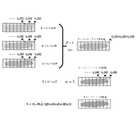
図3に示すように、イメージングの場合、サンプルは8つの表層に設定され、各表層は4つのサンプルストリップを形成するように分割される。駆動ユニット121は、サンプル20を駆動して、横方向に連続的に等速で移動させると、イメージングカメラ122cは、第1表層21の第1サンプルストリップ211をイメージングする。第1サンプル211のイメージングが完了した後、サンプル20は横方向に沿って戻る。第2表層22の第1サンプルストリップ221をイメージングすることができる。その後、第3表層23の第1サンプルストリップ231、第4表層24の第1サンプルストリップ241を順次イメージングすることができる。イメージングカメラ122cは、垂直方向に限られた数のイメージングの層を有するので、設定された数のイメージング層に達すると、例えば、第4表層24の第1サンプルストリップ241のイメージングが完了した後、サンプル20を駆動して、縦方向に沿って1つのサンプルストリップの幅で移動させ、第1表層21の第2サンプルストリップ212、第2表層22の第2サンプルストリップ222、第3表層23の第2サンプルストリップ232、第4表層24の第2サンプルストリップ242をイメージングすることができる。次に、上記の方式で、第1表層21~第4表層24の他のサンプルストリップをイメージングする。イメージングが完了した後、切除モジュール13によってイメージングされた第1表層21~第4表層24を切除することができる。切除後、サンプル20を駆動して、4つの表層の厚さの距離で移動させ、次に、第5表層~第8表層のイメージングを続ける。 As shown in FIG. 3, for imaging, the sample is set in 8 surface layers and each surface layer is divided to form 4 sample strips. When the
各サンプルストリップのイメージングプロセスでは、異なる画素で形成されたサンプル画像の計算式は次のとおりである。
図4(a)に示すように、イメージングの場合、サンプル20は、イメージング画素の配置方向に沿って移動する。イメージングの単一フレームの露光時間は、サンプル20が1行の画素を移動する時間と同じであるため、各行の画素がサンプル20の長さ方向に沿って複数のストライプ画像ブロックを順次形成する。前記複数のストライプ画像ブロックは、サンプル20に対する連続的なイメージングである。 As shown in FIG. 4A, in the case of imaging, the
本実施例の画像ブロック取得ユニット123は、時系列で得られた1つのサンプルストリップの各フレームの画像における第i行の画素のストライプ画像ブロックを取得するために使用される。ストライプ画像ブロックの計算式は次のとおりである。

なお、上記のストライプ画像は、1行の画素に対応する複数のストライプ画像をシフトしスプライスして形成される。それは、上述したストライプ画像である。即ち、N行の画素をそれぞれスプライスしてN個のストライプ画像を形成することができる。 The above stripe image is formed by shifting and splicing a plurality of stripe images corresponding to one row of pixels. It is the striped image mentioned above. That is, N rows of pixels can be spliced to form N stripe images.
前記復調モジュール14は、一つの表層の一つのサンプルストリップのストライプ画像を復調して光トモグラフィ画像を形成し、各表層の各サンプルストリップの光トモグラフィ画像を再構成して三次元画像を形成するために使用される。 The
前記復調モジュール14は、画像累積ユニット141と、復調ユニット142と、トモグラフィユニット143とを含む。前記画像累積ユニット141は、1つのサンプルストリップの少なくとも1行の画素のストライプ画像を累積して第1ストライプ画像を形成し、このサンプルストリップの少なくとも1行の画素のストライプ画像を累積して第2ストライプ画像を形成するために使用される。前記復調ユニット142は、第1ストライプ画像と第2ストライプ画像を光トモグラフィ画像に復調するために使用される。前記トモグラフィユニット143は、複数のサンプルストリップの光トモグラフィ画像を再構成して三次元画像を形成するために使用される。 The
上記のN個のストライプ画像を取得する場合、そのうちの1つ、2つ又は複数のストライプ画像を任意に選択して累積し、第1ストライプ画像を形成し、次に同じ方式で累積して第2ストライプ画像を取得することができる。上記の復調アルゴリズムにより取得されて光トモグラフィ画像がゼロになるのを防止するために、本実施例では、α個の画素でのストライプ画像に対応する変調強度の累積値が、β個の画素でのストライプ画像に対応する変調強度の累積値とは異なるように設定することができる When obtaining the above N stripe images, arbitrarily select and accumulate one, two or more of the stripe images to form a first stripe image, and then accumulate in the same manner to form a second stripe image. A 2-stripe image can be acquired. In order to prevent the optical tomography image obtained by the above demodulation algorithm from becoming zero, in this embodiment, the cumulative value of the modulation intensity corresponding to the stripe image at α pixels is set to β pixels. can be set to be different from the cumulative modulation intensity corresponding to the stripe image at
累積後、復調ユニット142によって、次の復調アルゴリズムに従って、対応するサンプルストリップの焦点面画像、即ち、光トモグラフィ画像を取得することができる。前記復調ユニット142で採用される復調アルゴリズムの復調式は、
Iin=c×|βI1-αI2|
である。
α、βは正の整数であり、cは0より大きい定数であり、I1はα個の画素で取得されたストライプ画像の累積合計であり、I2はβ個の画素で取得されたサンプル画像の累積合計である。α個の画素でのサンプル画像に対応する変調強度の累積値が、β個の画素でのサンプル画像に対応する変調強度の累積値とは異なる。After accumulation, the
Iin =c×|βI1 −αI2 |
is.
α, β are positive integers, c is a constant greater than0 , I1 is the cumulative sum of stripe images acquired with α pixels, andI2 is the sample acquired with β pixels. It is the cumulative sum of the images. The cumulative value of modulation intensity corresponding to the sample image with α pixels is different from the cumulative value of modulation intensity corresponding to the sample image with β pixels.

本実施例のストライプ画像の取得プロセスの説明を容易にするために、説明は、次に実施例に従って行われる。 To facilitate the description of the striped image acquisition process of this embodiment, the description will now be made according to the embodiment.
<実施例1>
図4(a)に示すように、サンプルがN行の画素の配置方向に沿って移動すると、時間t1~時間tN+M-1の間にN+M-1フレームの画像(Mは、完全なストライプ画像に対応するストライプ画像ブロックの数であり、この実施例では、Nは8であり、Mは9である)を取得することができる。N+M-1フレームの画像における各行の画素は、1つのストライプ画像ブロックに対応する。例えば、第1フレームの画像の第1行の画素のストライプ画像ブロックI1(1)、第2フレームの画像の第1行の画素のストライプ画像ブロックI2(1)、第Nフレームの画像の第1行の画素のストライプ画像ブロックIN(1)、及び第N+M-1フレームの画像の第1行の画素のストライプ画像ブロックI(N+M-1)(1)を取得することができる。上記のストライプ画像ブロックI1(1)、ストライプ画像ブロックI2(1)からストライプ画像ブロックI(N+M-1)(1)を順次スプライスして、ストライプ画像を形成することができる。対応する第2行の画素~第N行の画素をスプライスして、対応するストライプ画像を形成することができる。<Example 1>
As shown in FIG. 4(a), when the sample moves along the direction of arrangement of N rows of pixels, N+M−1 frames of images (M is a complete stripe) between time t1 and time tN+M−1 . number of stripe image blocks corresponding to the image, N=8 and M=9 in this example. Each row of pixels in the N+M-1 frame image corresponds to one stripe image block. For example, a stripe image block I1 (1) of pixels in the first row of the first frame image, a stripe image block I 2 (1) of pixels in the first row of the second frame image, and a stripe image block I2 (1) of the pixels in the Nth frame image A stripe image block IN (1) of pixels in the first row and a stripe image block I(N+M−1) (1) of pixels in the first row of the image of the N+M−1 frame can be obtained. A stripe image can be formed by sequentially splicing the stripe image block I1 (1), stripe image block I2 (1) to stripe image block I(N+M−1) (1). Corresponding 2nd row pixels through Nth row pixels can be spliced to form a corresponding stripe image.

<実施例2>
上記の復調アルゴリズムによって、各サンプルストリップの光トモグラフィ画像を順次取得することができる。トモグラフィユニット143は、すべての光トモグラフィ画像をスプライスして、立体三次元画像を形成することができる。 Optical tomography images of each sample strip can be acquired sequentially by the demodulation algorithm described above.
なお、サンプル20の縦方向の幅が、イメージングカメラ122cのN行の画素のイメージング領域の幅よりも小さい場合、各表層に1つのサンプルストリップのみがあり、サンプル20は、イメージング中に縦方向に移動する必要がない。サンプル20の縦方向の幅が、イメージングカメラ122cのN行の画素のイメージング領域の幅よりも小さく、その厚さが、イメージングカメラ122cがイメージングできる深さよりも小さい場合、例えば、表層が2つだけある場合、サンプル20は、横方向のみに往復移動すればよく、切除モジュール13によって表層切除を行う必要がない。サンプル20の幅が、イメージングカメラ122cのN行の画素イメージング領域の幅よりも小さく、その厚さが、設定された1つの表層の厚さよりも小さい場合、このサンプル20を1回のみスキャンしてイメージングすればよい。それは、二次元イメージングと見なすことができる。以上のことから、本実施例では、複数の二次元画像を重ね合わせて三次元画像を形成することがわかる。 It should be noted that if the longitudinal width of the
上述した本開示の具体的な実施形態は、本開示の保護範囲に対する制限を構成するものではない。本開示の技術的概念に従って行われた他の対応する変更及び修正は、本開示の特許請求の範囲の保護範囲に含まれるべきである。 The specific embodiments of the present disclosure described above do not constitute limitations on the protection scope of the present disclosure. Other corresponding changes and modifications made according to the technical concept of the present disclosure should fall within the protection scope of the claims of the present disclosure.
Claims (10)
Translated fromJapanese前記ビーム変調モジュールは、ビームを、対物レンズの焦点面に焦点を合わせ、対物レンズの焦点ぼけ面で発散することができる変調ビームに変調するために使用され、
前記イメージングモジュールは、カメラを使用して、変調ビームの照明下での同一のサンプルの少なくとも1つの表層の少なくとも1つのサンプルストリップを異なる画素でイメージングし、複数のサンプル画像を形成するために使用され、前記変調ビームは、異なる行画素の配置方向において異なる変調強度を有し、イメージング時に、前記異なる行画素の前記配置方向に沿ってサンプルストライプが移動し、これにより前記異なる行の各行の画素が、前記配置方向に沿って複数のストライプ画像ブロックを順次形成し、前記異なる行の各行の画素により形成された前記複数のストライプ画像ブロックは、同一のサンプルの前記複数のサンプル画像のうちの対応する一つのサンプル画像をスプライスするために使用され、
前記切除モジュールは、サンプルのイメージングされた表層を切除するために使用され、
前記復調モジュールは、一つの表層の一つのサンプルストリップのサンプル画像を復調して光トモグラフィ画像を形成し、各表層の各サンプルストリップの光トモグラフィ画像を再構成して三次元画像を形成するために使用され、複数のサンプル画像を形成することを特徴とする高スループット光トモグラフィ三次元イメージングシステム。A high-throughput optical tomography three-dimensional imaging system comprising a beam modulation module, an imaging module, an ablation module, and a demodulation module,
the beam modulation module is used to modulate the beam into a modulated beam that can be focused on the focal plane of the objective lens and diverged at the defocus plane of the objective lens;
The imaging module is used to image at least one sample strip of at least one surface layer of the same sample under illumination of the modulated beam with different pixels using acamera to form a plurality of sample images. , the modulated beam hasdifferent modulation intensities in different row pixel arrangement directions, andduring imaging, the sample stripe moves along the arrangement direction of the different row pixels, so that the pixels in each row of the different rows are and sequentially forming a plurality of stripe image blocks along the arrangement direction, wherein the plurality of stripe image blocks formed by the pixels of each row of the different rows correspond to the plurality of sample images of the same sample. used to splice one sample image,
the ablation module is used to ablate the imaged superficial layer of the sample;
The demodulation module demodulates the sample image of one sample strip of one surface layer to form an optical tomography image, and reconstructs the optical tomography image of each sample strip of each surface layer to form a three-dimensional image. A high-throughput optical tomography three-dimensional imaging system used for and characterizedby forming multiple sample images .
I(i)=Iinf(i)+Iout
I(i)は、第i画素で形成されたサンプル画像であり、f(i)は、サンプル画像I(i)に対応する変調強度であり、Iinは、サンプル画像の焦点面画像であり、Ioutはサンプル画像の焦点ぼけ面画像であり、
前記復調モジュールでは、復調式は、
Iin=c×|βI1-αI2|
であり、
α、βは正の整数であり、cは0より大きい定数であり、I1はα行の画素で取得されたサンプル画像の累積合計であり、I2はβ行の画素で取得されたサンプル画像の累積合計であり、β×(α行の画素でのサンプル画像に対応する変調強度の累積値)は、α×(β行の画素でのサンプル画像に対応する変調強度の累積値)とは異なる、ことを特徴とする請求項1に記載の高スループット光トモグラフィ三次元イメージングシステム。In said imaging module, the formula for the sample image of the formed sample strip is:
I(i)=Iinf (i)+Iout
I(i) is the sample image formed bythe ith pixel, f(i) is the modulation intensity corresponding to the sample image I(i), and Iin is the focal plane image of the sample image. , Iout is the out-of-focus image of the sample image, and
In said demodulation module, the demodulation formula is:
Iin =c×|βI1 −αI2 |
and
α, β are positive integers, c is a constant greater than0 , I1 is the cumulative sum of sampled images taken at pixels inrow α, andI2 is the sample taken at pixels inrow β is the cumulative sum of the image,β × ( cumulative modulation intensity corresponding to the sample image at the pixels in the αrow) isα × ( cumulative modulation intensity corresponding to the sample image at the pixels in the βrow) and 2. The high-throughput optical tomography three-dimensional imaging system of claim 1, wherein .


Applications Claiming Priority (3)
| Application Number | Priority Date | Filing Date | Title |
|---|---|---|---|
| CN201811296073.4ACN111122567B (en) | 2018-11-01 | 2018-11-01 | High-flux optical tomography three-dimensional imaging system |
| CN201811296073.4 | 2018-11-01 | ||
| PCT/CN2019/098367WO2020088014A1 (en) | 2018-11-01 | 2019-07-30 | High-throughput optical tomography three-dimensional imaging system |
Publications (2)
| Publication Number | Publication Date |
|---|---|
| JP2022511676A JP2022511676A (en) | 2022-02-01 |
| JP7190034B2true JP7190034B2 (en) | 2022-12-14 |
Family
ID=70464702
Family Applications (1)
| Application Number | Title | Priority Date | Filing Date |
|---|---|---|---|
| JP2021523973AActiveJP7190034B2 (en) | 2018-11-01 | 2019-07-30 | High-throughput optical tomography 3D imaging system |
Country Status (8)
| Country | Link |
|---|---|
| US (1) | US11906723B2 (en) |
| EP (1) | EP3876022A4 (en) |
| JP (1) | JP7190034B2 (en) |
| KR (1) | KR102593253B1 (en) |
| CN (1) | CN111122567B (en) |
| AU (1) | AU2019372392B2 (en) |
| CA (1) | CA3118393C (en) |
| WO (1) | WO2020088014A1 (en) |
Families Citing this family (4)
| Publication number | Priority date | Publication date | Assignee | Title |
|---|---|---|---|---|
| US11521401B2 (en)* | 2020-07-31 | 2022-12-06 | Bridging Biosciences, LLC | Fertility window prediction using a convolutional neural network (CNN) and other learning methods |
| CN113340911A (en)* | 2021-06-24 | 2021-09-03 | 北京兆维电子(集团)有限责任公司 | Micro-optical system for arc periphery defect detection |
| CN116593434A (en)* | 2023-04-17 | 2023-08-15 | 华中科技大学苏州脑空间信息研究院 | Line illumination modulation double-color tomography system |
| CN117705775B (en)* | 2024-02-05 | 2024-04-26 | 中国科学院长春光学精密机械与物理研究所 | Multicolor fluorescence microscopic imaging system, imaging method and automatic focusing method |
Citations (6)
| Publication number | Priority date | Publication date | Assignee | Title |
|---|---|---|---|---|
| JP2000506634A (en) | 1997-04-04 | 2000-05-30 | イシス イノヴェーション リミテッド | Microscope imaging apparatus and method |
| JP2004109348A (en) | 2002-09-17 | 2004-04-08 | Institute Of Physical & Chemical Research | Microscope equipment |
| JP2004515780A (en) | 2000-12-13 | 2004-05-27 | メディカル リサーチ カウンシル | Apparatus and method for imaging a tissue specimen |
| JP2005525551A (en) | 2002-05-14 | 2005-08-25 | アマシャム バイオサイエンス ユーケイ リミテッド | How to evaluate biofilm |
| CN101661159A (en) | 2008-08-25 | 2010-03-03 | 麦克奥迪实业集团有限公司 | Two-dimensional modulation technique-based method for acquiring shear-layer images |
| WO2018094290A1 (en) | 2016-11-18 | 2018-05-24 | Tissuevision, Inc. | Automated tissue section capture, indexing and storage system and methods |
Family Cites Families (18)
| Publication number | Priority date | Publication date | Assignee | Title |
|---|---|---|---|---|
| JP2773607B2 (en)* | 1993-10-28 | 1998-07-09 | 日本電気株式会社 | Microscope lighting device |
| JP5307439B2 (en)* | 2007-04-23 | 2013-10-02 | オリンパス株式会社 | Laser microscope |
| US9285575B2 (en)* | 2009-01-26 | 2016-03-15 | President And Fellows Of Harvard College | Systems and methods for selective detection and imaging in coherent Raman microscopy by spectral excitation shaping |
| DE102010013830A1 (en)* | 2010-03-26 | 2011-09-29 | Carl Zeiss Microlmaging Gmbh | Microscope e.g. stimulated Raman scattering microscopy for observing biological specimen, has detector for detecting fluorescence produced in sample, and thermal image camera for reading detection signal of detector |
| JP5454424B2 (en)* | 2010-09-03 | 2014-03-26 | ソニー株式会社 | Imaging method |
| US20120127464A1 (en)* | 2010-11-22 | 2012-05-24 | Canon Kabushiki Kaisha | Light source apparatus |
| US8649024B2 (en)* | 2010-12-03 | 2014-02-11 | Zygo Corporation | Non-contact surface characterization using modulated illumination |
| CN102928970B (en)* | 2012-10-19 | 2014-10-29 | 华中科技大学 | Method and system for rapidly three-dimensionally microimaging large sample |
| CN103207449B (en)* | 2013-04-17 | 2015-04-29 | 华中科技大学 | Structured light quick scanning microscopic imaging method |
| TWI486625B (en)* | 2013-05-16 | 2015-06-01 | Univ Nat Central | Digital holographic microscope |
| JP2015215509A (en)* | 2014-05-12 | 2015-12-03 | パナソニックIpマネジメント株式会社 | Display apparatus, display method and program |
| CN104061879B (en)* | 2014-06-19 | 2017-11-24 | 四川大学 | A kind of structural light three-dimensional face shape vertical survey method continuously scanned |
| CN108020503B (en)* | 2017-11-20 | 2020-09-08 | 苏州博芮恩光电科技有限公司 | Light sheet illumination microscopic section imaging system and imaging result processing method |
| CN108593605B (en)* | 2018-04-23 | 2020-02-28 | 清华大学 | Three-dimensional high-speed wide-field tomography method and device |
| KR102760925B1 (en)* | 2018-12-11 | 2025-02-03 | 삼성전자주식회사 | Inspecting apparatus based on hyper HSI(Hyper Spectral Imaging) |
| US10839542B2 (en)* | 2019-01-29 | 2020-11-17 | The Chinese University Of Hong Kong | Systems and methods for 3D laparoscopic surface reconstruction |
| DE102020213715A1 (en)* | 2020-11-01 | 2022-05-05 | Carl Zeiss Microscopy Gmbh | Device and method for rapid three-dimensional acquisition of image data |
| US20230045982A1 (en)* | 2021-08-11 | 2023-02-16 | Vergent Research Pty Ltd | Shuttered Light Field Display |
- 2018
- 2018-11-01CNCN201811296073.4Apatent/CN111122567B/enactiveActive
- 2019
- 2019-07-30JPJP2021523973Apatent/JP7190034B2/enactiveActive
- 2019-07-30KRKR1020217016637Apatent/KR102593253B1/enactiveActive
- 2019-07-30AUAU2019372392Apatent/AU2019372392B2/enactiveActive
- 2019-07-30CACA3118393Apatent/CA3118393C/enactiveActive
- 2019-07-30WOPCT/CN2019/098367patent/WO2020088014A1/ennot_activeCeased
- 2019-07-30EPEP19878242.7Apatent/EP3876022A4/enactivePending
- 2021
- 2021-04-30USUS17/302,330patent/US11906723B2/enactiveActive
Patent Citations (6)
| Publication number | Priority date | Publication date | Assignee | Title |
|---|---|---|---|---|
| JP2000506634A (en) | 1997-04-04 | 2000-05-30 | イシス イノヴェーション リミテッド | Microscope imaging apparatus and method |
| JP2004515780A (en) | 2000-12-13 | 2004-05-27 | メディカル リサーチ カウンシル | Apparatus and method for imaging a tissue specimen |
| JP2005525551A (en) | 2002-05-14 | 2005-08-25 | アマシャム バイオサイエンス ユーケイ リミテッド | How to evaluate biofilm |
| JP2004109348A (en) | 2002-09-17 | 2004-04-08 | Institute Of Physical & Chemical Research | Microscope equipment |
| CN101661159A (en) | 2008-08-25 | 2010-03-03 | 麦克奥迪实业集团有限公司 | Two-dimensional modulation technique-based method for acquiring shear-layer images |
| WO2018094290A1 (en) | 2016-11-18 | 2018-05-24 | Tissuevision, Inc. | Automated tissue section capture, indexing and storage system and methods |
Non-Patent Citations (1)
| Title |
|---|
| Vincent Poher ET AL,"Improved sectioning in a slit scanning confocal microscope",OPTICS LETTERS,2008年08月15日,Vol. 33, No. 16,pages 1813-1815 |
Also Published As
| Publication number | Publication date |
|---|---|
| AU2019372392B2 (en) | 2023-01-19 |
| WO2020088014A1 (en) | 2020-05-07 |
| JP2022511676A (en) | 2022-02-01 |
| CN111122567B (en) | 2022-09-16 |
| CA3118393C (en) | 2023-06-27 |
| KR102593253B1 (en) | 2023-10-24 |
| EP3876022A1 (en) | 2021-09-08 |
| US20210333536A1 (en) | 2021-10-28 |
| EP3876022A4 (en) | 2021-12-29 |
| CA3118393A1 (en) | 2020-05-07 |
| AU2019372392A1 (en) | 2021-06-03 |
| CN111122567A (en) | 2020-05-08 |
| KR20210086694A (en) | 2021-07-08 |
| US11906723B2 (en) | 2024-02-20 |
Similar Documents
| Publication | Publication Date | Title |
|---|---|---|
| JP7190034B2 (en) | High-throughput optical tomography 3D imaging system | |
| DE112019004851B4 (en) | Device for fast volumetric fluorescence microscopy using time-multiplexed light sheets | |
| CN109187459B (en) | An adaptive scanning wide-field high-throughput tomographic imaging method and device | |
| AU2010200554B2 (en) | Microscope with a viewing direction perpendicular to the illumination direction | |
| JP7235861B2 (en) | High-throughput optical tomography imaging method and imaging system | |
| KR20200070313A (en) | Image reconstruction method, device and microscopic imaging device | |
| EP3520074B1 (en) | Method for the analysis of spatial and temporal information of samples by means of optical microscopy | |
| CN115248197A (en) | A three-dimensional imaging device and imaging method | |
| CN112654911B (en) | Microscope device with virtual objective | |
| KR101391180B1 (en) | Structured Illumination Imaging Method Using Laser Bean Scanning | |
| CN109211854A (en) | Multi-beam multi-photon rescanning microscopy imaging device |
Legal Events
| Date | Code | Title | Description |
|---|---|---|---|
| A621 | Written request for application examination | Free format text:JAPANESE INTERMEDIATE CODE: A621 Effective date:20210610 | |
| A521 | Request for written amendment filed | Free format text:JAPANESE INTERMEDIATE CODE: A523 Effective date:20211227 | |
| A977 | Report on retrieval | Free format text:JAPANESE INTERMEDIATE CODE: A971007 Effective date:20220530 | |
| A131 | Notification of reasons for refusal | Free format text:JAPANESE INTERMEDIATE CODE: A131 Effective date:20220628 | |
| A521 | Request for written amendment filed | Free format text:JAPANESE INTERMEDIATE CODE: A523 Effective date:20220927 | |
| TRDD | Decision of grant or rejection written | ||
| A01 | Written decision to grant a patent or to grant a registration (utility model) | Free format text:JAPANESE INTERMEDIATE CODE: A01 Effective date:20221108 | |
| A61 | First payment of annual fees (during grant procedure) | Free format text:JAPANESE INTERMEDIATE CODE: A61 Effective date:20221202 | |
| R150 | Certificate of patent or registration of utility model | Ref document number:7190034 Country of ref document:JP Free format text:JAPANESE INTERMEDIATE CODE: R150 |