JP7189766B2 - Methods of coating microstructured components - Google Patents
Methods of coating microstructured componentsDownload PDFInfo
- Publication number
- JP7189766B2 JP7189766B2JP2018518412AJP2018518412AJP7189766B2JP 7189766 B2JP7189766 B2JP 7189766B2JP 2018518412 AJP2018518412 AJP 2018518412AJP 2018518412 AJP2018518412 AJP 2018518412AJP 7189766 B2JP7189766 B2JP 7189766B2
- Authority
- JP
- Japan
- Prior art keywords
- component
- coating
- nozzle
- substrate
- microstructured
- Prior art date
- Legal status (The legal status is an assumption and is not a legal conclusion. Google has not performed a legal analysis and makes no representation as to the accuracy of the status listed.)
- Active
Links
Images


Classifications
- A—HUMAN NECESSITIES
- A61—MEDICAL OR VETERINARY SCIENCE; HYGIENE
- A61M—DEVICES FOR INTRODUCING MEDIA INTO, OR ONTO, THE BODY; DEVICES FOR TRANSDUCING BODY MEDIA OR FOR TAKING MEDIA FROM THE BODY; DEVICES FOR PRODUCING OR ENDING SLEEP OR STUPOR
- A61M15/00—Inhalators
- A61M15/0065—Inhalators with dosage or measuring devices
- A—HUMAN NECESSITIES
- A61—MEDICAL OR VETERINARY SCIENCE; HYGIENE
- A61M—DEVICES FOR INTRODUCING MEDIA INTO, OR ONTO, THE BODY; DEVICES FOR TRANSDUCING BODY MEDIA OR FOR TAKING MEDIA FROM THE BODY; DEVICES FOR PRODUCING OR ENDING SLEEP OR STUPOR
- A61M11/00—Sprayers or atomisers specially adapted for therapeutic purposes
- A61M11/006—Sprayers or atomisers specially adapted for therapeutic purposes operated by applying mechanical pressure to the liquid to be sprayed or atomised
- A—HUMAN NECESSITIES
- A61—MEDICAL OR VETERINARY SCIENCE; HYGIENE
- A61M—DEVICES FOR INTRODUCING MEDIA INTO, OR ONTO, THE BODY; DEVICES FOR TRANSDUCING BODY MEDIA OR FOR TAKING MEDIA FROM THE BODY; DEVICES FOR PRODUCING OR ENDING SLEEP OR STUPOR
- A61M15/00—Inhalators
- A61M15/0065—Inhalators with dosage or measuring devices
- A61M15/0068—Indicating or counting the number of dispensed doses or of remaining doses
- A—HUMAN NECESSITIES
- A61—MEDICAL OR VETERINARY SCIENCE; HYGIENE
- A61M—DEVICES FOR INTRODUCING MEDIA INTO, OR ONTO, THE BODY; DEVICES FOR TRANSDUCING BODY MEDIA OR FOR TAKING MEDIA FROM THE BODY; DEVICES FOR PRODUCING OR ENDING SLEEP OR STUPOR
- A61M15/00—Inhalators
- A61M15/009—Inhalators using medicine packages with incorporated spraying means, e.g. aerosol cans
- B—PERFORMING OPERATIONS; TRANSPORTING
- B01—PHYSICAL OR CHEMICAL PROCESSES OR APPARATUS IN GENERAL
- B01J—CHEMICAL OR PHYSICAL PROCESSES, e.g. CATALYSIS OR COLLOID CHEMISTRY; THEIR RELEVANT APPARATUS
- B01J2/00—Processes or devices for granulating materials, e.g. fertilisers in general; Rendering particulate materials free flowing in general, e.g. making them hydrophobic
- B01J2/02—Processes or devices for granulating materials, e.g. fertilisers in general; Rendering particulate materials free flowing in general, e.g. making them hydrophobic by dividing the liquid material into drops, e.g. by spraying, and solidifying the drops
- B01J2/04—Processes or devices for granulating materials, e.g. fertilisers in general; Rendering particulate materials free flowing in general, e.g. making them hydrophobic by dividing the liquid material into drops, e.g. by spraying, and solidifying the drops in a gaseous medium
- B—PERFORMING OPERATIONS; TRANSPORTING
- B01—PHYSICAL OR CHEMICAL PROCESSES OR APPARATUS IN GENERAL
- B01J—CHEMICAL OR PHYSICAL PROCESSES, e.g. CATALYSIS OR COLLOID CHEMISTRY; THEIR RELEVANT APPARATUS
- B01J2/00—Processes or devices for granulating materials, e.g. fertilisers in general; Rendering particulate materials free flowing in general, e.g. making them hydrophobic
- B01J2/02—Processes or devices for granulating materials, e.g. fertilisers in general; Rendering particulate materials free flowing in general, e.g. making them hydrophobic by dividing the liquid material into drops, e.g. by spraying, and solidifying the drops
- B01J2/06—Processes or devices for granulating materials, e.g. fertilisers in general; Rendering particulate materials free flowing in general, e.g. making them hydrophobic by dividing the liquid material into drops, e.g. by spraying, and solidifying the drops in a liquid medium
- B—PERFORMING OPERATIONS; TRANSPORTING
- B05—SPRAYING OR ATOMISING IN GENERAL; APPLYING FLUENT MATERIALS TO SURFACES, IN GENERAL
- B05B—SPRAYING APPARATUS; ATOMISING APPARATUS; NOZZLES
- B05B1/00—Nozzles, spray heads or other outlets, with or without auxiliary devices such as valves, heating means
- B05B1/02—Nozzles, spray heads or other outlets, with or without auxiliary devices such as valves, heating means designed to produce a jet, spray, or other discharge of particular shape or nature, e.g. in single drops, or having an outlet of particular shape
- B05B1/04—Nozzles, spray heads or other outlets, with or without auxiliary devices such as valves, heating means designed to produce a jet, spray, or other discharge of particular shape or nature, e.g. in single drops, or having an outlet of particular shape in flat form, e.g. fan-like, sheet-like
- B05B1/042—Outlets having two planes of symmetry perpendicular to each other, one of them defining the plane of the jet
- B—PERFORMING OPERATIONS; TRANSPORTING
- B05—SPRAYING OR ATOMISING IN GENERAL; APPLYING FLUENT MATERIALS TO SURFACES, IN GENERAL
- B05B—SPRAYING APPARATUS; ATOMISING APPARATUS; NOZZLES
- B05B1/00—Nozzles, spray heads or other outlets, with or without auxiliary devices such as valves, heating means
- B05B1/14—Nozzles, spray heads or other outlets, with or without auxiliary devices such as valves, heating means with multiple outlet openings; with strainers in or outside the outlet opening
- B05B1/16—Nozzles, spray heads or other outlets, with or without auxiliary devices such as valves, heating means with multiple outlet openings; with strainers in or outside the outlet opening having selectively- effective outlets
- B—PERFORMING OPERATIONS; TRANSPORTING
- B05—SPRAYING OR ATOMISING IN GENERAL; APPLYING FLUENT MATERIALS TO SURFACES, IN GENERAL
- B05B—SPRAYING APPARATUS; ATOMISING APPARATUS; NOZZLES
- B05B1/00—Nozzles, spray heads or other outlets, with or without auxiliary devices such as valves, heating means
- B05B1/14—Nozzles, spray heads or other outlets, with or without auxiliary devices such as valves, heating means with multiple outlet openings; with strainers in or outside the outlet opening
- B05B1/20—Perforated pipes or troughs, e.g. spray booms; Outlet elements therefor
- B05B1/202—Perforated pipes or troughs, e.g. spray booms; Outlet elements therefor comprising inserted outlet elements
- B—PERFORMING OPERATIONS; TRANSPORTING
- B05—SPRAYING OR ATOMISING IN GENERAL; APPLYING FLUENT MATERIALS TO SURFACES, IN GENERAL
- B05B—SPRAYING APPARATUS; ATOMISING APPARATUS; NOZZLES
- B05B11/00—Single-unit hand-held apparatus in which flow of contents is produced by the muscular force of the operator at the moment of use
- B05B11/0005—Components or details
- B05B11/0027—Means for neutralising the actuation of the sprayer ; Means for preventing access to the sprayer actuation means
- B05B11/0032—Manually actuated means located downstream the discharge nozzle for closing or covering it, e.g. shutters
- B—PERFORMING OPERATIONS; TRANSPORTING
- B05—SPRAYING OR ATOMISING IN GENERAL; APPLYING FLUENT MATERIALS TO SURFACES, IN GENERAL
- B05B—SPRAYING APPARATUS; ATOMISING APPARATUS; NOZZLES
- B05B13/00—Machines or plants for applying liquids or other fluent materials to surfaces of objects or other work by spraying, not covered by groups B05B1/00 - B05B11/00
- B05B13/02—Means for supporting work; Arrangement or mounting of spray heads; Adaptation or arrangement of means for feeding work
- B05B13/04—Means for supporting work; Arrangement or mounting of spray heads; Adaptation or arrangement of means for feeding work the spray heads being moved during spraying operation
- B05B13/0436—Installations or apparatus for applying liquid or other fluent material to elongated bodies, e.g. light poles, pipes
- B—PERFORMING OPERATIONS; TRANSPORTING
- B05—SPRAYING OR ATOMISING IN GENERAL; APPLYING FLUENT MATERIALS TO SURFACES, IN GENERAL
- B05D—PROCESSES FOR APPLYING FLUENT MATERIALS TO SURFACES, IN GENERAL
- B05D7/00—Processes, other than flocking, specially adapted for applying liquids or other fluent materials to particular surfaces or for applying particular liquids or other fluent materials
- B05D7/24—Processes, other than flocking, specially adapted for applying liquids or other fluent materials to particular surfaces or for applying particular liquids or other fluent materials for applying particular liquids or other fluent materials
- B—PERFORMING OPERATIONS; TRANSPORTING
- B81—MICROSTRUCTURAL TECHNOLOGY
- B81C—PROCESSES OR APPARATUS SPECIALLY ADAPTED FOR THE MANUFACTURE OR TREATMENT OF MICROSTRUCTURAL DEVICES OR SYSTEMS
- B81C1/00—Manufacture or treatment of devices or systems in or on a substrate
- B—PERFORMING OPERATIONS; TRANSPORTING
- B81—MICROSTRUCTURAL TECHNOLOGY
- B81C—PROCESSES OR APPARATUS SPECIALLY ADAPTED FOR THE MANUFACTURE OR TREATMENT OF MICROSTRUCTURAL DEVICES OR SYSTEMS
- B81C1/00—Manufacture or treatment of devices or systems in or on a substrate
- B81C1/00015—Manufacture or treatment of devices or systems in or on a substrate for manufacturing microsystems
- B81C1/00206—Processes for functionalising a surface, e.g. provide the surface with specific mechanical, chemical or biological properties
- B—PERFORMING OPERATIONS; TRANSPORTING
- B81—MICROSTRUCTURAL TECHNOLOGY
- B81C—PROCESSES OR APPARATUS SPECIALLY ADAPTED FOR THE MANUFACTURE OR TREATMENT OF MICROSTRUCTURAL DEVICES OR SYSTEMS
- B81C1/00—Manufacture or treatment of devices or systems in or on a substrate
- B81C1/00015—Manufacture or treatment of devices or systems in or on a substrate for manufacturing microsystems
- B81C1/00341—Processes for manufacturing microsystems not provided for in groups B81C1/00023 - B81C1/00261
- B—PERFORMING OPERATIONS; TRANSPORTING
- B81—MICROSTRUCTURAL TECHNOLOGY
- B81C—PROCESSES OR APPARATUS SPECIALLY ADAPTED FOR THE MANUFACTURE OR TREATMENT OF MICROSTRUCTURAL DEVICES OR SYSTEMS
- B81C1/00—Manufacture or treatment of devices or systems in or on a substrate
- B81C1/00349—Creating layers of material on a substrate
- B81C1/0038—Processes for creating layers of materials not provided for in groups B81C1/00357 - B81C1/00373
- B—PERFORMING OPERATIONS; TRANSPORTING
- B81—MICROSTRUCTURAL TECHNOLOGY
- B81C—PROCESSES OR APPARATUS SPECIALLY ADAPTED FOR THE MANUFACTURE OR TREATMENT OF MICROSTRUCTURAL DEVICES OR SYSTEMS
- B81C1/00—Manufacture or treatment of devices or systems in or on a substrate
- B81C1/00642—Manufacture or treatment of devices or systems in or on a substrate for improving the physical properties of a device
- B81C1/0065—Mechanical properties
- B81C1/00682—Treatments for improving mechanical properties, not provided for in B81C1/00658 - B81C1/0065
- C—CHEMISTRY; METALLURGY
- C03—GLASS; MINERAL OR SLAG WOOL
- C03C—CHEMICAL COMPOSITION OF GLASSES, GLAZES OR VITREOUS ENAMELS; SURFACE TREATMENT OF GLASS; SURFACE TREATMENT OF FIBRES OR FILAMENTS MADE FROM GLASS, MINERALS OR SLAGS; JOINING GLASS TO GLASS OR OTHER MATERIALS
- C03C17/00—Surface treatment of glass, not in the form of fibres or filaments, by coating
- C03C17/28—Surface treatment of glass, not in the form of fibres or filaments, by coating with organic material
- C03C17/30—Surface treatment of glass, not in the form of fibres or filaments, by coating with organic material with silicon-containing compounds
- C—CHEMISTRY; METALLURGY
- C09—DYES; PAINTS; POLISHES; NATURAL RESINS; ADHESIVES; COMPOSITIONS NOT OTHERWISE PROVIDED FOR; APPLICATIONS OF MATERIALS NOT OTHERWISE PROVIDED FOR
- C09D—COATING COMPOSITIONS, e.g. PAINTS, VARNISHES OR LACQUERS; FILLING PASTES; CHEMICAL PAINT OR INK REMOVERS; INKS; CORRECTING FLUIDS; WOODSTAINS; PASTES OR SOLIDS FOR COLOURING OR PRINTING; USE OF MATERIALS THEREFOR
- C09D183/00—Coating compositions based on macromolecular compounds obtained by reactions forming in the main chain of the macromolecule a linkage containing silicon, with or without sulfur, nitrogen, oxygen, or carbon only; Coating compositions based on derivatives of such polymers
- C09D183/04—Polysiloxanes
- C09D183/08—Polysiloxanes containing silicon bound to organic groups containing atoms other than carbon, hydrogen, and oxygen
- A—HUMAN NECESSITIES
- A61—MEDICAL OR VETERINARY SCIENCE; HYGIENE
- A61M—DEVICES FOR INTRODUCING MEDIA INTO, OR ONTO, THE BODY; DEVICES FOR TRANSDUCING BODY MEDIA OR FOR TAKING MEDIA FROM THE BODY; DEVICES FOR PRODUCING OR ENDING SLEEP OR STUPOR
- A61M2205/00—General characteristics of the apparatus
- A61M2205/02—General characteristics of the apparatus characterised by a particular materials
- A61M2205/0238—General characteristics of the apparatus characterised by a particular materials the material being a coating or protective layer
- A—HUMAN NECESSITIES
- A61—MEDICAL OR VETERINARY SCIENCE; HYGIENE
- A61M—DEVICES FOR INTRODUCING MEDIA INTO, OR ONTO, THE BODY; DEVICES FOR TRANSDUCING BODY MEDIA OR FOR TAKING MEDIA FROM THE BODY; DEVICES FOR PRODUCING OR ENDING SLEEP OR STUPOR
- A61M2205/00—General characteristics of the apparatus
- A61M2205/70—General characteristics of the apparatus with testing or calibration facilities
- A—HUMAN NECESSITIES
- A61—MEDICAL OR VETERINARY SCIENCE; HYGIENE
- A61M—DEVICES FOR INTRODUCING MEDIA INTO, OR ONTO, THE BODY; DEVICES FOR TRANSDUCING BODY MEDIA OR FOR TAKING MEDIA FROM THE BODY; DEVICES FOR PRODUCING OR ENDING SLEEP OR STUPOR
- A61M2205/00—General characteristics of the apparatus
- A61M2205/75—General characteristics of the apparatus with filters
- A61M2205/7545—General characteristics of the apparatus with filters for solid matter, e.g. microaggregates
- A—HUMAN NECESSITIES
- A61—MEDICAL OR VETERINARY SCIENCE; HYGIENE
- A61M—DEVICES FOR INTRODUCING MEDIA INTO, OR ONTO, THE BODY; DEVICES FOR TRANSDUCING BODY MEDIA OR FOR TAKING MEDIA FROM THE BODY; DEVICES FOR PRODUCING OR ENDING SLEEP OR STUPOR
- A61M2205/00—General characteristics of the apparatus
- A61M2205/75—General characteristics of the apparatus with filters
- A61M2205/7563—General characteristics of the apparatus with filters with means preventing clogging of filters
- A—HUMAN NECESSITIES
- A61—MEDICAL OR VETERINARY SCIENCE; HYGIENE
- A61M—DEVICES FOR INTRODUCING MEDIA INTO, OR ONTO, THE BODY; DEVICES FOR TRANSDUCING BODY MEDIA OR FOR TAKING MEDIA FROM THE BODY; DEVICES FOR PRODUCING OR ENDING SLEEP OR STUPOR
- A61M2207/00—Methods of manufacture, assembly or production
- B—PERFORMING OPERATIONS; TRANSPORTING
- B05—SPRAYING OR ATOMISING IN GENERAL; APPLYING FLUENT MATERIALS TO SURFACES, IN GENERAL
- B05B—SPRAYING APPARATUS; ATOMISING APPARATUS; NOZZLES
- B05B11/00—Single-unit hand-held apparatus in which flow of contents is produced by the muscular force of the operator at the moment of use
- B05B11/01—Single-unit hand-held apparatus in which flow of contents is produced by the muscular force of the operator at the moment of use characterised by the means producing the flow
- B05B11/10—Pump arrangements for transferring the contents from the container to a pump chamber by a sucking effect and forcing the contents out through the dispensing nozzle
- B05B11/109—Pump arrangements for transferring the contents from the container to a pump chamber by a sucking effect and forcing the contents out through the dispensing nozzle the dispensing stroke being affected by the stored energy of a spring
- B05B11/1091—Pump arrangements for transferring the contents from the container to a pump chamber by a sucking effect and forcing the contents out through the dispensing nozzle the dispensing stroke being affected by the stored energy of a spring being first hold in a loaded state by locking means or the like, then released
- B—PERFORMING OPERATIONS; TRANSPORTING
- B05—SPRAYING OR ATOMISING IN GENERAL; APPLYING FLUENT MATERIALS TO SURFACES, IN GENERAL
- B05D—PROCESSES FOR APPLYING FLUENT MATERIALS TO SURFACES, IN GENERAL
- B05D2518/00—Other type of polymers
- B05D2518/10—Silicon-containing polymers
- B05D2518/12—Ceramic precursors (polysiloxanes, polysilazanes)
- B—PERFORMING OPERATIONS; TRANSPORTING
- B05—SPRAYING OR ATOMISING IN GENERAL; APPLYING FLUENT MATERIALS TO SURFACES, IN GENERAL
- B05D—PROCESSES FOR APPLYING FLUENT MATERIALS TO SURFACES, IN GENERAL
- B05D5/00—Processes for applying liquids or other fluent materials to surfaces to obtain special surface effects, finishes or structures
- B05D5/08—Processes for applying liquids or other fluent materials to surfaces to obtain special surface effects, finishes or structures to obtain an anti-friction or anti-adhesive surface
- B—PERFORMING OPERATIONS; TRANSPORTING
- B81—MICROSTRUCTURAL TECHNOLOGY
- B81C—PROCESSES OR APPARATUS SPECIALLY ADAPTED FOR THE MANUFACTURE OR TREATMENT OF MICROSTRUCTURAL DEVICES OR SYSTEMS
- B81C2201/00—Manufacture or treatment of microstructural devices or systems
- B81C2201/01—Manufacture or treatment of microstructural devices or systems in or on a substrate
- B81C2201/0161—Controlling physical properties of the material
- B—PERFORMING OPERATIONS; TRANSPORTING
- B81—MICROSTRUCTURAL TECHNOLOGY
- B81C—PROCESSES OR APPARATUS SPECIALLY ADAPTED FOR THE MANUFACTURE OR TREATMENT OF MICROSTRUCTURAL DEVICES OR SYSTEMS
- B81C2201/00—Manufacture or treatment of microstructural devices or systems
- B81C2201/01—Manufacture or treatment of microstructural devices or systems in or on a substrate
- B81C2201/0174—Manufacture or treatment of microstructural devices or systems in or on a substrate for making multi-layered devices, film deposition or growing
- B81C2201/0197—Processes for making multi-layered devices not provided for in groups B81C2201/0176 - B81C2201/0192
Landscapes
- Engineering & Computer Science (AREA)
- Health & Medical Sciences (AREA)
- Life Sciences & Earth Sciences (AREA)
- Manufacturing & Machinery (AREA)
- Microelectronics & Electronic Packaging (AREA)
- Chemical & Material Sciences (AREA)
- General Health & Medical Sciences (AREA)
- Anesthesiology (AREA)
- Heart & Thoracic Surgery (AREA)
- Hematology (AREA)
- Animal Behavior & Ethology (AREA)
- Biomedical Technology (AREA)
- Public Health (AREA)
- Veterinary Medicine (AREA)
- Pulmonology (AREA)
- Bioinformatics & Cheminformatics (AREA)
- Chemical Kinetics & Catalysis (AREA)
- Organic Chemistry (AREA)
- Mechanical Engineering (AREA)
- Wood Science & Technology (AREA)
- Biophysics (AREA)
- Materials Engineering (AREA)
- Geochemistry & Mineralogy (AREA)
- General Chemical & Material Sciences (AREA)
- Molecular Biology (AREA)
- Pharmaceuticals Containing Other Organic And Inorganic Compounds (AREA)
- Nitrogen Condensed Heterocyclic Rings (AREA)
- Medicinal Preparation (AREA)
- Steroid Compounds (AREA)
- Acyclic And Carbocyclic Compounds In Medicinal Compositions (AREA)
- Pyrrole Compounds (AREA)
- Application Of Or Painting With Fluid Materials (AREA)
Description
Translated fromJapanese 本発明は、マイクロフルイディクスの分野に関する。特に、本発明は、極性表面を有するマイクロ構造基板又はコンポーネントの表面を改質、特に疎水化する方法に関する。
本発明は、表面改質を含むマイクロ構造コンポーネントにも関する。さらに、本発明は、改質表面を有するマイクロ流体システムのマイクロ構造コンポーネント、特にノズルシステムに関する。
さらに、本発明は、放出装置、特に、好ましくは医療分野における流体用噴霧器に関する。
最後に、本発明は、マイクロ構造コンポーネントの表面改質の評価方法に関する。The present invention relates to the field of microfluidics. In particular, the invention relates to a method for modifying, in particular hydrophobizing, the surface of microstructured substrates or components with polar surfaces.
The invention also relates to microstructured components that include surface modifications. Furthermore, the invention relates to microstructured components of microfluidic systems, in particular nozzle systems, with modified surfaces.
Furthermore, the invention relates to a delivery device, in particular a sprayer for fluids, preferably in the medical field.
Finally, the invention relates to a method for evaluating surface modification of microstructured components.
医療においては、噴霧器は、特に呼吸器疾患を治療するための吸入デバイスとして使用される。例えば、喘息性疾患及び慢性気管支炎は、吸入療法を用いて治療される。現代の専門医の吸入療法にとっては、気管支喘息及び慢性気管支炎(COPD-慢性閉塞性肺疾患とも呼ばれる)が主な適応症である。これら2つの病気は「閉塞性呼吸器疾患」であり、合計で全呼吸器疾患の約90%を占める
慢性気管支炎は、その呼吸器力の特徴的な進行性劣化のせいで、世界中の病弱及び死亡の主因の1つである。特に、合併症及びそれに伴う入院は、気管支喘息及びCOPDが世界中の医療予算を高コストにすることを意味する。これらの疾患が全世界で増加している事実のため、今後これら2つの呼吸器疾患の治療及びそれらに関する研究が高い優先順位になる必要がある。
吸入による薬物療法の目的は、肺に活性物質を蓄積させることである。該療法に用いられる多くの化合物は全身効果をも有し得るので、吸入によるこれらの活性物質の適用は、経口又は静脈内投与を超える多くの利点を有し得る。理想的に、罹患臓器のみが治療され、局所的に高い有効濃度を達成することができる。さらに、作用開始は一般的に迅速に起こり、全身の副作用はまれである。最近の数年間で新しい気管支拡張薬及び抗炎症薬が市場に現れるにつれて、多くの喘息及びCOPD患者の状況は改善されてきた。それにもかかわらず、この改善の大半はデバイス開発の分野の技術革新にも依存している(Ambrosino, N.and P.Paggiaro, The management of asthma and chronic obstructive pulmonary disease: current status and future perspectives. Expert. Rev. Respir. Med., 2012.6(1): pp.117-127参照)。In medicine, nebulizers are used as inhalation devices, especially for treating respiratory ailments. For example, asthmatic diseases and chronic bronchitis are treated using inhalation therapy. Bronchial asthma and chronic bronchitis (COPD - also called chronic obstructive pulmonary disease) are the main indications for modern specialist inhalation therapy. These two diseases are 'obstructive respiratory diseases' and together account for about 90% of all respiratory diseases. It is one of the leading causes of infirmity and mortality. In particular, complications and associated hospitalizations mean that bronchial asthma and COPD are costly to healthcare budgets worldwide. Due to the fact that these diseases are increasing all over the world, the treatment of these two respiratory diseases and their research need to become a high priority in the future.
The aim of drug therapy by inhalation is to accumulate the active substance in the lungs. Application of these active agents by inhalation can have many advantages over oral or intravenous administration, as many compounds used in such therapies can also have systemic effects. Ideally, only diseased organs are treated and high local effective concentrations can be achieved. Furthermore, onset of action generally occurs rapidly and systemic side effects are rare. The situation of many asthma and COPD patients has improved in recent years as new bronchodilators and anti-inflammatory drugs have appeared on the market. Nevertheless, much of this improvement also relies on innovation in the field of device development (Ambrosino, N. and P. Paggiaro, The management of asthma and chronic obstructive pulmonary disease: current status and future perspectives. Expert Rev. Respir. Med., 2012.6(1): pp.117-127).
吸入療法の成功は、吸入される医薬品の量及び気道内におけるその分布に左右される。それらの分布は、多くの様々な状況で広範な要因によって影響される。これらの要因には、エアロゾル自体の特徴的な性質、適用するために用いられる吸入デバイス、患者が行なう吸入の性質及び気道の解剖学的形態が含まれる(Ganderton, D., Targeted delivery of inhaled drugs: current challenges and future goals. J. Aerosol Med., 1999. 12 Suppl 1: pp. S3-8; Pavia, D., Efficacy and safety of inhalation therapy in chronic obstructive pulmonary disease and asthma. Respirology, 1997. 2 Suppl 1: pp. S5-10参照)。
エアロゾルの1つの特に重要な性質は、その粒径分布である。これは気道におけるエアロゾル粒子の蓄積に重大な影響を及ぼすからである。2~5μmの空気力学径を有するエアロゾル粒子は、より小さい細気管支及び末梢気道へ吸入されるときにうまく機能する(Ariyananda, P.L., J.E.Agnew, and S.W.Clarke, Aerosol delivery systems for bronchial asthma. Postgrad. Med. J., 1996. 72(845): pp. 151-156参照)。対照的に、相対的に大きい粒子は上気道と衝突するが、より小さい粒子は最後に肺胞に行き、再び吐き出さられるものさえある。
医薬品を吸入によって適用するために、多くの携帯式デバイス(デバイス又は吸入器とも呼ばれる)が利用可能である。これらには、クロロフルオロカーボン(CFC)又はヒドロフルオロアルカン(HFA)を用いて操作する加圧式定量吸入器(pMDI)、及びドライパウダー吸入器(DPI)が含まれる。長年、CFC-MDI吸入器が気管支喘息及び慢性気管支炎治療の基礎を形成した。しかしながら、多くの患者は、この吸入器群の使用に苦労し、それらの吸入療法では最適の治療効果を受けなかった。pMDIの限界及び環境に優しい無噴霧剤吸入器への動きが、新しい吸入デバイスの開発を加速した。The success of inhalation therapy depends on the amount of drug inhaled and its distribution within the respiratory tract. Their distribution is influenced by a wide range of factors in many different situations. These factors include the characteristic properties of the aerosol itself, the inhalation device used to apply it, the nature of the inhalation performed by the patient and the airway anatomy (Ganderton, D., Targeted delivery of inhaled drugs). J. Aerosol Med., 1999. 12 Suppl 1: pp. S3-8; Pavia, D., Efficacy and safety of inhalation therapy in chronic obstructive pulmonary disease and asthma. Respirology, 1997. 2 Suppl 1: pp. S5-10).
One particularly important property of an aerosol is its particle size distribution. This is because it has a significant impact on the accumulation of aerosol particles in the respiratory tract. Aerosol particles with an aerodynamic diameter of 2-5 μm work well when inhaled into smaller bronchioles and small airways (Ariyananda, PL, JEAgnew, and SWClarke, Aerosol delivery systems for bronchial asthma. Postgrad. Med. J., 1996. 72(845): pp. 151-156). In contrast, relatively large particles collide with the upper respiratory tract, while smaller particles end up in the alveoli and some are even exhaled again.
Many hand-held devices (also called devices or inhalers) are available for applying medications by inhalation. These include pressurized metered dose inhalers (pMDI) operating with chlorofluorocarbons (CFCs) or hydrofluoroalkanes (HFAs), and dry powder inhalers (DPI). For many years, CFC-MDI inhalers have formed the cornerstone of bronchial asthma and chronic bronchitis treatment. However, many patients struggled with this group of inhalers and did not receive optimal therapeutic response from their inhalation therapy. The limitations of pMDIs and the move towards environmentally friendly aerosol-free inhalers have accelerated the development of new inhalation devices.
Ganderton(上記参照)によれば、最適な吸入デバイスは、下記要件を満たす:
・肺内における活性成分の高蓄積
・遅いエアロゾル放出
・吸入デバイスを取り扱いやすい
・用量投与後の患者へのフィードバック
・計量器又は含量指標の存在
・便利な形式
・環境に優しい
・再利用可能。According to Ganderton (see above), optimal inhalation devices meet the following requirements:
- High accumulation of active ingredient in lung - Slow aerosol release - Easy to handle inhalation device - Feedback to patient after dose administration - Presence of meter or content indicator - Convenient format - Environmentally friendly - Reusable.
Boehringer Ingelheimが2003年にRespimat(登録商標) Soft Mist(商標)吸入器を市場にもたらしたとき、上記要件の大多数を満たす新しい吸入デバイスが利用可能になった。Respimat(登録商標) Soft Mist(商標)吸入器は、バネの機械エネルギーと2つの液体ジェットの衝突を用いてエアロゾルを生成する無噴霧剤噴霧器である。エアロゾルを発生させるためのその異なる原理のため、この吸入器は吸入デバイスの上記カテゴリーのいずれにも割り当てられず;代わりに、該吸入器は吸入デバイスの新型、すなわちソフトミスト吸入器(SMI)を作り出した。SMIのエアロゾル雲はpMDI又はDPIのエアロゾル雲より遅く、ずっと高い微粒子分率(fine particle fraction)(FPF)を有する。噴霧の相対的に長い持続時間のため、患者はエアロゾルの吸入を効果的にコーディネートすることができ、相対的に高い微粒子分率は、より深い気道におけるその蓄積を非常に効果的にする。高分率の呼吸用エアロゾル粒子は、適用量を減らせるようにし、ひいては望ましくない医薬品効果が生じる可能性を減らす(Dalby, R., M. Spallek, and T. Voshaar, A review of the development of Respimat Soft Mist Inhaler. Int. J. Pharm., 2004. 283(1-2): pp.1-9参照)。WO 91/14468 A1は、吸入すべき一定量の液体医薬品の無噴霧剤投与用のSMI型装置を開示する。 When Boehringer Ingelheim brought the Respimat(R) Soft Mist(TM) inhaler to the market in 2003, a new inhalation device was made available that met most of the above requirements. The Respimat® Soft Mist™ inhaler is a propellant-free nebulizer that uses the mechanical energy of a spring and the collision of two liquid jets to create an aerosol. Due to its different principle for generating aerosols, this inhaler is not assigned to any of the above categories of inhalation devices; created. The SMI aerosol cloud is slower than the pMDI or DPI aerosol cloud and has a much higher fine particle fraction (FPF). The relatively long duration of nebulization allows the patient to effectively coordinate the inhalation of the aerosol, and the relatively high fine particle fraction makes its deposition in the deeper airways very effective. A high fraction of respirable aerosol particles allows for lower doses, thus reducing the potential for undesirable pharmaceutical effects (Dalby, R., M. Spallek, and T. Voshaar, A review of the development of Respimat Soft Mist Inhaler. Int. J. Pharm., 2004. 283(1-2): pp.1-9). WO 91/14468 A1 discloses an SMI-type device for the aerosol-free administration of a fixed amount of liquid medicament to be inhaled.
従って、従来技術の他の吸入方法に比べて、SMI型デバイス又は吸入器は、ずっと効果的かつ穏やかな様式で呼吸器疾患を治療できるようにする。WO 2009/047173 A2はSMIデバイスの例を開示する。そこに記載の噴霧器では、液体医薬製剤が容器内に貯蔵され、運搬管を通って圧力チャンバーに運搬されて最終的にノズルを通して放出される。ノズルは液体入口側と液体出口側を有する。液体入口側には、開口部があり、これを通って圧力チャンバーからの液体がノズルに入ることができる。そして反対側で、液体は、開口部を出る液体ジェットが互いに衝突し、結果として噴霧されるように方向づけられた2つのノズル開口部を通って出る。この噴霧原理を下記では「ダブルジェット衝突」(DJI)と呼ぶ。
SMI型吸入器は、好ましくは水又は水-エタノール混合物に基づく液体製剤の放出に適している。数秒以内に、好ましくは1~2秒の噴霧時間又は持続時間にわたって、SMI型吸入器は、少量の液体製剤を必要な治療用量での吸入療法に適したエアロゾルに微粒化することができる。このデバイスを用いて、100μl未満、好ましくは20μl未満の量を、例えば、吸入可能割合が好ましくは60%より多く及び/又は実際には治療的に有効な量に相当するようなストロークを用いてエアロゾルに微粒化することができる。
ここで論じるSMI型吸入器を用いて、医薬品溶液が1000バールまで、好ましくは300バールまでの高圧(好ましくは50バールより大きい)によって、患者が吸入できる低速の呼吸用エアロゾル雲に変換される。Thus, compared to other inhalation methods of the prior art, SMI-type devices or inhalers allow respiratory ailments to be treated in a much more effective and gentle manner. WO 2009/047173 A2 discloses an example of an SMI device. In the nebulizer described therein, a liquid pharmaceutical formulation is stored in a container, conveyed through a conveying tube into a pressure chamber and finally discharged through a nozzle. The nozzle has a liquid inlet side and a liquid outlet side. On the liquid inlet side there is an opening through which liquid from the pressure chamber can enter the nozzle. And on the opposite side, the liquid exits through two nozzle openings oriented such that the liquid jets exiting the openings collide with each other and are consequently sprayed. This atomization principle is referred to below as "double jet impingement" (DJI).
SMI type inhalers are suitable for delivery of liquid formulations, preferably based on water or water-ethanol mixtures. Within seconds, preferably over a nebulization time or duration of 1-2 seconds, the SMI type inhaler can atomize a small amount of liquid formulation into an aerosol suitable for inhalation therapy at the required therapeutic dose. With this device a volume of less than 100 μl, preferably less than 20 μl, for example using strokes such that the respirable fraction is preferably greater than 60% and/or actually corresponds to a therapeutically effective amount. It can be atomized into an aerosol.
With the SMI-type inhaler discussed here, a pharmaceutical solution is converted by high pressure up to 1000 bar, preferably up to 300 bar (preferably greater than 50 bar) into a slow breathing aerosol cloud that can be inhaled by the patient.
小さいノズル開口部を有する吸入器を使用するときには、ノズル出口が噴霧器の使用時に不純物としてノズル出口に付着する製剤溶液残渣によって封鎖されてくることがまれにある。これは、液体ジェットを偏向させ、特にDJIノズルを使用するときには微粒子分率を変える。マイクロノズルの領域における粒子の沈殿は、ノズルを封鎖するか又は詰まらせる恐れがあり、この噴霧器の機能性に有害作用を及ぼす。この現象については、用語「ジェット偏向」によって以下に要約する。この作用の出現が製剤の構成成分及び組成に依存することは当然である。しかしながら、一般に、他の製剤よりこの作用の可能性が高い製剤における粒子蓄積のために起こることが多いノズル封鎖を減らすことも望ましいであろう。蓄積の発生は、例えば、易流動性懸濁液を含有するマイクロ流体システムから知られている。
マイクロチャネルにおける目詰まりの発生は複雑な現象である。可能性のある機構には、引力の存在に起因するチャネル壁面への粒子の結合及びその後の流路内の蓄積によるか又は「水力学的架橋」による目詰まりが含まれる。水力学的架橋は、チャネル径より小さい粒子が狭窄部に同時に到達してから前記狭窄部を封鎖する現象を指す。この作用は、コロイドの反発力と加えられた引張力の両方に依存する。粒子は、例えば内部力、ブラウン運動、沈降又は妨害によってチャネル壁に輸送される。結合する粒子の有効性は、常に引力と反発力の比によって決まる。
例えば、複雑な製剤、例えばエタノール溶媒に基づく製剤を含むSMI及びDJIノズル技術の適用範囲を広げることが望ましい。この点で有益な用途は、吸入コルチコイド療法の分野にある。特に高効率コルチコステロイドの分野では、少量の製剤を遅速噴霧雲に変換するためにSMIを使用する選択肢は、現在の通常の吸入デバイスの場合より有効な吸入を期待できることを意味する。When using an inhaler with a small nozzle opening, it is rare for the nozzle outlet to become blocked by formulation solution residue that adheres to the nozzle outlet as a contaminant during use of the nebulizer. This deflects the liquid jet and changes the fine particle fraction, especially when using DJI nozzles. Particle sedimentation in the area of the micronozzle can block or clog the nozzle, adversely affecting the functionality of the atomizer. This phenomenon is summarized below by the term "jet deflection". Of course, the appearance of this effect depends on the components and composition of the formulation. In general, however, it would also be desirable to reduce nozzle blockage, which often occurs due to particle build-up in formulations where this effect is more likely than in other formulations. The occurrence of accumulation is known, for example, from microfluidic systems containing free-flowing suspensions.
The occurrence of clogging in microchannels is a complex phenomenon. Possible mechanisms include clogging due to binding of particles to the channel walls due to the presence of attractive forces and subsequent accumulation within the flow path or due to "hydraulic bridging". Hydraulic bridging refers to a phenomenon in which particles smaller than the channel diameter reach a constriction at the same time and then block the constriction. This action depends on both the repulsive force of the colloid and the applied tensile force. Particles are transported to the channel walls by, for example, internal forces, Brownian motion, sedimentation or obstruction. The effectiveness of binding particles is always determined by the ratio of attractive and repulsive forces.
For example, it is desirable to extend the coverage of SMI and DJI nozzle technology to include complex formulations, such as formulations based on ethanol solvents. A beneficial application in this respect is in the field of inhaled corticoid therapy. Especially in the area of high-efficiency corticosteroids, the option of using SMIs to convert small formulations into slow-moisture clouds means that more effective inhalation can be expected than with current conventional inhalation devices.
気管支喘息の基本的な薬理学的療法は、単独で又は他の物質と組合せて投与される長時間作用性β2刺激薬(LABA)を含有する吸入コルチコステロイド(ICS)を含む。慢性気管支炎の薬物療法の第1の選択肢は、LABA及びLAMA(長時間作用性抗ムスカリン拮抗薬)の範囲からの気管支拡張薬の単剤投与である。しかしながら、コルチコイド療法へのCOPDの感受性によっては、ICSによる療法も可能である。
SMI又はDJI技術を用いる吸入療法を拡張すると、より穏やかでより効果的な様式で薬物を投与できるので一般的に望ましいことになる。しかしながら、この場合、特に複雑な製剤では、活性成分が吸入器に付着し、ひいては噴霧パターンを劣化させ、究極的にノズル封鎖に至る恐れがあるという問題がある。
さらに、長時間安定性を有する医薬品製剤は、吸入器内で反応、例えば溶けにくい化合物の沈殿を引き起こす恐れがあり、これが今度は粒子付着のためのノズル封鎖を引き起こし得る。
SMI型吸入器の使用は、さらに、望ましくない医薬品作用の発生を減らすことができるので、粒子付着の防止並びにSMI型吸入器及びDJI型ノズルの使用の拡張に関して多くの試験が行なわれた。
ノズル開口部の領域に不純粒子が付着しないようにするため、WO 2004/089551 A1は、液体出口側の外面がマイクロ構造化又はナノ構造化されている、DJI型ノズル及びSMI型吸入器用のマイクロ構造又はナノ構造を開示する。
さらに、WO 2010/112358 A2は、特に、異なる材料、特にガラス及びシリコンから成るコンポーネントのマイクロ構造表面のコーティング方法であって、その表面をまず最初に活性化してからコーティングする方法を開示する。コンポーネントは好ましくは、SMI型吸入器に使用できるDJIノズルである。酸化溶液、塩基性溶液又は酸性酸化溶液によってコンポーネント表面を活性化する。
上記方法及びDJIノズルの改変によって、ノズル出口開口部の目詰まり又は封鎖を遅らせることができ、阻止できる場合もある。しかしながら、これらの方法のいくつかは、特にWO 2004/089551 A1のマイクロ構造出口開口部の場合、非常に複雑かつ高価であり、或いは確実に所望の結果に至らないことが多い。Basic pharmacological therapy for bronchial asthma includes inhaled corticosteroids (ICS) containing long-acting β2 -agonists (LABAs) administered alone or in combination with other agents. The first line of pharmacotherapy for chronic bronchitis is single-agent bronchodilators from the range of LABAs and LAMAs (long-acting antimuscarinic antagonists). However, depending on the susceptibility of COPD to corticoid therapy, therapy with ICS is also possible.
Extending inhalation therapy using SMI or DJI technology would generally be desirable as it would allow the drug to be administered in a gentler and more effective manner. In this case, however, there is the problem that, especially with complex formulations, the active ingredient can stick to the inhaler, thus degrading the spray pattern and ultimately leading to nozzle blockage.
Furthermore, pharmaceutical formulations with long-term stability can cause reactions in the inhaler, such as precipitation of sparingly soluble compounds, which in turn can cause nozzle blockage due to particle adhesion.
Since the use of SMI inhalers can also reduce the occurrence of undesirable pharmaceutical effects, many studies have been conducted on preventing particle deposition and extending the use of SMI inhalers and DJI nozzles.
In order to keep the area of the nozzle opening free of contaminant particles, WO 2004/089551 A1 describes a microstructure for DJI nozzles and SMI inhalers whose outer surface on the liquid outlet side is microstructured or nanostructured. A structure or nanostructure is disclosed.
Furthermore, WO 2010/112358 A2 discloses a method of coating microstructured surfaces, in particular of components made of different materials, in particular glass and silicon, wherein the surface is first activated and then coated. The component is preferably a DJI nozzle that can be used with SMI type inhalers. The component surface is activated with an oxidizing solution, a basic solution or an acidic oxidizing solution.
The above methods and modifications to the DJI nozzle can delay and in some cases prevent clogging or blockage of the nozzle exit opening. However, some of these methods, especially in the case of the microstructured exit openings of WO 2004/089551 A1, are either very complicated and expensive, or often do not reliably lead to the desired results.
従って、本発明の目的は、従来技術に存在する上記問題を軽減するか又は少なくとも実質的に回避することである。
さらに、本発明の別の目的は、より広い範囲の活性成分の組合せの使用を可能にし、かなり良い使用及び性能特性を達成し、特にセルフクリーニング特性を有する、吸入器からの液体の無噴霧剤放出用の改良されたノズルシステムを提供することのみならず、ノズルの使用特性を改善し、特にノズルに関するセルフクリーニング特性を達成できるか又はノズルの表面特性を変えることができる方法を提供することである。
本発明の別の目的は、吸入器、特にSMI型吸入器の使用範囲を拡張することである。SUMMARY OF THE INVENTION It is therefore an object of the present invention to alleviate or at least substantially avoid the above-mentioned problems existing in the prior art.
Furthermore, another object of the present invention is a liquid spray-free formulation from an inhaler that allows the use of a wider range of active ingredient combinations, achieves considerably better use and performance characteristics, and in particular has self-cleaning properties. By providing an improved nozzle system for ejection, as well as improving the usage characteristics of the nozzle, and in particular by providing a method by which self-cleaning characteristics for the nozzle can be achieved or the surface characteristics of the nozzle can be changed. be.
Another object of the present invention is to extend the range of use of inhalers, in particular SMI type inhalers.
本発明の第一態様によれば、本発明は、請求項1に記載のマイクロ構造基板の表面を改質する方法に関し;関連従属請求項は、本発明のこの態様のさらなる有利な実施形態を提示する。
本発明の第二態様によれば、本発明は、請求項62又は請求項63に記載のマイクロ構造コンポーネントに関し;関連従属請求項は、本発明のこの態様のさらなる有利な実施形態を提示する。
本発明のさらなる態様によれば、本発明は、請求項77に記載の流体放出装置に関し;関連従属請求項は、本発明のこの態様のさらなる有利な実施形態を提示する。
本発明のさらなる態様によれば、本発明は、マイクロ構造コンポーネントとして表面改質を評価する請求項85に記載の方法にも関し;関連従属請求項は、本発明のこの態様のさらなる有利な実施形態を提示する。
反復を回避するため、本発明のたった1つの態様に関して後述する特殊な特性、特徴、設計及び実施形態、並びに利点等は、この態様を具体的に述べる必要なく、本発明の他の態様に準用することは当然である。
値、数又は範囲を以下に提示しないのは限界であるとみなすべきであり;代わりに、当業者は、個々の場合又は適用において述べた範囲又は詳細から、本発明の範囲を逸脱することなく当然に逸脱し得ることも自明である。
さらに、以下に述べる全ての値、パラメーター等は、標準化されたか若しくは明示的に述べられた決定方法又は関連技術分野の当業者にとって日常的である決定方法を用いて決定又は定義することができる。
さらに、当業者は、全ての質量に基づくか又は体積に基づく百分率値を合計100%になるように選択できることが分かるのは当然であり;これは自明なことである。
以下、これに基づいて、本発明をさらに詳細に説明する。According to a first aspect of the invention, the invention relates to a method for modifying the surface of a microstructured substrate according to
According to a second aspect of the invention, the invention relates to a microstructured component according to claim 62 or claim 63; the related dependent claims present further advantageous embodiments of this aspect of the invention.
According to a further aspect of the invention, the invention relates to a fluid ejection device according to claim 77; the related dependent claims present further advantageous embodiments of this aspect of the invention.
According to a further aspect of the invention, the invention also relates to a method of evaluating a surface modification as a microstructured component according to
To avoid repetition, specific features, features, designs and embodiments, advantages, etc., described below with respect to only one aspect of the invention apply mutatis mutandis to other aspects of the invention without having to specifically mention this aspect. It is natural to do so.
Any values, numbers or ranges that are not given below should be considered limiting; instead, one of ordinary skill in the art would not depart from the scope of the invention from ranges or details stated in individual cases or applications. Of course, it is also self-evident that deviations can be made.
Furthermore, all values, parameters, etc., described below can be determined or defined using standardized or explicitly stated determination methods or determination methods that are routine to those skilled in the relevant art.
Further, it should be appreciated that one skilled in the art may select all mass-based or volume-based percentage values to add up to 100%; this is self-explanatory.
Based on this, the present invention will be described in further detail below.
〔発明を実施するための形態〕
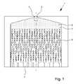
従って、本発明の第一態様によれば、本発明は、特に高圧用途のための、極性表面を有する基板又は流体コンポーネント、特にマイクロ構造コンポーネント(例えばノズル体)の表面を改質する方法であって、基板又はマイクロ構造コンポーネントを改質試薬と接触させ、特に改質試薬で処理し、コンポーネント表面と改質試薬との間の化学的及び/又は物理的相互作用によって基板の表面特性を改変し、改質試薬は、少なくとも1種の改質剤を含み、この改質剤は、シラン、シロキサン、ポリシロキサン及び/又はシリコナート並びにその混合物から成る群より選択される、方法に関する。
本発明の脈絡の範囲内では、基板又はマイクロ構造コンポーネントの表面を改質することによって、その表面特性を、物質、特にマイクロ構造基板又はコンポーネントを越えて又は通って導かれる液体溶液又は分散系の残渣の付着を必要に応じて増減できるように改質することができる。
本発明の脈絡の範囲内では、基板又はマイクロ構造コンポーネントをコーティングすることによって、特に標的様式で基板又はコンポーネントの表面と、物質、特に表面を越えて導かれる流体との間の相互作用を標的様式で変えるか又は減らすことができるような標的様式で、基板又はコンポーネントの表面特性を操作することができる。[Mode for carrying out the invention]
Thus, according to a first aspect of the invention, the invention is a method of modifying the surface of a substrate or fluidic component, in particular a microstructured component (e.g. nozzle body), having a polar surface, in particular for high pressure applications. contacting, in particular treating, a substrate or microstructured component with a modifying reagent to modify the surface properties of the substrate by chemical and/or physical interactions between the component surface and the modifying reagent. , the modifying reagent comprises at least one modifier, which modifier is selected from the group consisting of silanes, siloxanes, polysiloxanes and/or siliconates and mixtures thereof.
Within the context of the present invention, by modifying the surface of a substrate or microstructured component, its surface properties can be changed to that of a substance, particularly a liquid solution or dispersion conducted over or through the microstructured substrate or component. Modifications can be made to increase or decrease residue adhesion as desired.
Within the context of the present invention, by coating a substrate or microstructured component, the interaction between the surface of the substrate or component and a substance, in particular a fluid directed over the surface, is targeted in a particularly targeted manner. The surface properties of a substrate or component can be manipulated in a targeted manner such that the .
本発明の脈絡の範囲内では、基板を通って又は越えて導かれる流体による基板表面の濡れを特に下げることができる。これは、特に表面を疎水化することによって行なわれ、すなわち、表面を疎水性物質で処理し、この結果として、基板の表面エネルギーが低減し、特に疎水性物質はもはや以前と同程度には表面と相互作用できない。
本発明の脈絡の範囲内では、表面を改質試薬で処理することは、基板表面の物理的及び/又は化学的性質を変えることを意味するものと解釈すべきである。
いずれの適切な様式でも改質試薬で基板又はマイクロ構造コンポーネントを処理することができる。しかしながら、通常、基板を改質試薬の溶液若しくは分散系と接触させ、特に改質試薬の溶液若しくは分散系を噴霧するか又はそれに浸す。
特に、本発明の脈絡の範囲内では、表面改質は驚くべきことに、高圧用途においてさえもすぐれた結果をもたらすことができる。本発明の方法を用いて得ることができる表面改質は、通常、1,000バールまでの高圧でさえ、特に50~1,000バール、特に200~600バール、好ましくは250~350バールの範囲内の圧力で損傷又は破壊されない(改質表面と実質的に平行に流れる層流について試験した)。Within the context of the present invention, the wetting of the substrate surface by fluids conducted through or over the substrate can be particularly reduced. This is done in particular by hydrophobizing the surface, i.e. treating it with a hydrophobic substance, as a result of which the surface energy of the substrate is reduced, in particular the hydrophobic substance no longer affects the surface to the same extent as before. cannot interact with
Within the context of the present invention, treating a surface with a modifying agent should be taken to mean altering the physical and/or chemical properties of the substrate surface.
A substrate or microstructure component can be treated with the modifying reagent in any suitable manner. Generally, however, the substrate is contacted with a solution or dispersion of the modifying reagent, in particular sprayed or dipped into the solution or dispersion of the modifying reagent.
In particular, within the context of the present invention, surface modification can surprisingly yield excellent results even in high pressure applications. The surface modification obtainable using the process of the invention is usually even at high pressures up to 1,000 bar, especially at pressures in the range from 50 to 1,000 bar, especially from 200 to 600 bar, preferably from 250 to 350 bar. Not damaged or destroyed (tested for laminar flow running substantially parallel to the modified surface).
本発明の脈絡の範囲内では、マイクロ構造基板の極性表面は、好ましくは極性官能化学基によって形成される。本発明の脈絡の範囲内では、極性官能化学基は、ヒドロキシ基、エステル基、カルボニル基、アミン基、スルファン基、又は永久双極子モーメントを有し、特に他の極性基との相互作用に受容性のマイクロ構造基板の表面を与える同様の基のような化学官能基であると理解すべきである。
本発明の脈絡の範囲内では、マイクロ構造コンポーネントは、特にそれらの外側又は内側の表面に、例えば、チャネル又はリリーフの形態で、100μm以下、特に50μm以下、好ましくは20μm以下、特に好ましくは2μm~8μmの範囲内の少なくとも1つの空間方向に伸長している構造を含むコンポーネントであると理解すべきである。本発明の脈絡の範囲内では、コーティング試薬を用いる変換によって又はコーティングを適用(塗布)することによって、構造の形状を保持し、形状を覆わないか又はその輪郭の鮮明さを低減させずに、特に微細なマイクロ構造の表面特性を改変することができる。
本発明の脈絡の範囲内では、マイクロ構造コンポーネントは、少なくとも2つの異なる材料を含むことができる。本発明の脈絡の範囲内では、マイクロ構造コンポーネントが少なくとも2つの異なる材料を含む場合、これらの材料は通常各々極性表面を有する。
本発明の脈絡の範囲内では、マイクロ構造コンポーネントの全ての材料が極性表面を有することが有効であることも判明した。Within the context of the present invention, the polar surface of the microstructured substrate is preferably formed by polar functional chemical groups. Within the context of the present invention, polar functional chemical groups are hydroxy groups, ester groups, carbonyl groups, amine groups, sulfane groups or have a permanent dipole moment and are particularly receptive to interactions with other polar groups. should be understood to be chemical functional groups such as the same groups that provide the surface of the microstructured substrate of the nature.
Within the context of the present invention, the microstructured components, in particular on their outer or inner surface, for example in the form of channels or reliefs, are 100 μm or less, in particular 50 μm or less, preferably 20 μm or less, particularly preferably 2 μm or less. It should be understood as a component comprising structures extending in at least one spatial direction within 8 μm. Within the context of the present invention, the shape of the structure is retained by conversion with a coating reagent or by applying a coating, without covering the shape or reducing the sharpness of its contours. In particular, the surface properties of fine microstructures can be modified.
Within the context of the invention, the microstructural component can comprise at least two different materials. Within the context of the present invention, when a microstructured component comprises at least two different materials, these materials usually each have a polar surface.
Within the context of the present invention, it has also been found useful for all materials of the microstructured component to have a polar surface.
本発明の脈絡の範囲内では、コンポーネントの材料の表面は一般に一緒に改質される。コンポーネント表面を一緒に又は同時に改質すると、各材料を別々に疎水化しなくてよいので、簡単かつ迅速な改質となる。一緒に又は同時にコーティングするとは、コンポーネントの種々の材料が、好ましくは時間及び/又は位置に関して一緒に改質されることを意味すると理解すべきである。これは、コンポーネントの種々の材料をまず最初に相互に接続してからこの複合材の表面を、特に改質試薬又は改質剤を用いる変換によって改変することを意味する。
本発明の脈絡の範囲内でマイクロ構造コンポーネントに使用できる材料に関しては、コンポーネントが、例えばマイクロ構造上のカバーの形態で、ガラス、特にケイ酸塩ガラス、好ましくは石英ガラス及び/又はホウケイ酸ガラスを含むのが有効なことが判った。ガラス、特にケイ酸塩ガラスは、形状を保持し、頑丈で化学的に不活性な材料である。特に、ガラスは通常、例えば薬物又は医薬組成物に含まれる有機化合物と反応しない。Within the context of the present invention, the surfaces of the materials of the component are generally modified together. Modification of the component surfaces together or simultaneously results in simple and rapid modification, as each material does not have to be hydrophobized separately. Coating together or simultaneously should be understood to mean that the various materials of the component are modified together, preferably with respect to time and/or position. This means that the various materials of the component are first connected to each other and then the surface of this composite is modified, in particular by transformation using modifying reagents or modifiers.
As regards the materials that can be used for the microstructured component within the context of the present invention, the component, for example in the form of a microstructured cover, is made of glass, in particular silicate glass, preferably quartz glass and/or borosilicate glass. It has been found useful to include Glass, especially silicate glass, is a shape-retaining, robust and chemically inert material. In particular, glasses generally do not react with organic compounds contained in, for example, drugs or pharmaceutical compositions.
さらに、コンポーネントがシリコン、特に元素シリコンを含む場合にも本発明の脈絡の範囲内で良い結果が得られた。コンポーネントが元素シリコンを含む場合、コンポーネントの少なくとも一部がシリコンウェーハから成るか又はシリコンウェーハを含有するのが有効なことが判った。ベースメタロイドとしてのシリコンは常に薄い天然の酸化物層で覆われているので、元素シリコンは極性表面を有する。この酸化物層は例外的に改質試薬又は改質剤と結合することができる。さらに、マイクロ構造上にシリコンを非常に効果的に生成することができる。すなわち、簡単なやり方でマイクロ構造をシリコン、特にシリコンウェーハに適用することができる。これは、例えば、エッチング等の半導体技術において確立されている方法で行なうことができる。
本発明の脈絡の範囲内では、コンポーネントが元素シリコン及びガラスを含み、特に元素シリコン及びガラスから成る場合に特に良い結果が得られる。従って、本発明の脈絡の範囲内では、マイクロ構造コンポーネントは、ガラスと、特に天然の酸化物層を有する元素シリコンとから成ることが好ましい。Moreover, good results have also been obtained within the context of the present invention when the component contains silicon, in particular elemental silicon. If the component contains elemental silicon, it has proven useful for at least part of the component to consist of or contain a silicon wafer. Elemental silicon has a polar surface because silicon as the base metalloid is always covered with a thin native oxide layer. This oxide layer can exceptionally be combined with modifying reagents or modifiers. Furthermore, silicon can be produced very effectively on microstructures. Thus, the microstructures can be applied in a simple manner to silicon, in particular silicon wafers. This can be done, for example, by methods established in semiconductor technology, such as etching.
Within the context of the present invention, particularly good results are obtained when the component comprises, and in particular consists of, the elements silicon and glass. Therefore, within the context of the present invention, the microstructural component preferably consists of glass and, in particular, elemental silicon with a native oxide layer.
コンポーネンに用いる材料の形状については、これは大きく変動し得る。しかしながら、コンポーネントの異なる材料が特に少なくとも実質的に四角形、好ましくはプレート様であるのが有効であることが判った。好ましくは、コンポーネントの異なる材料はガラスウェーハ及び/又はシリコンウェーハである。四角形又はプレート様デザインの材料を有すると、機械的加工を簡単にし、簡単なやり方で材料を接続できるようになる。材料は通常それらの最大表面を介して接続されるので、特にウェーハのようなプレート様材料の場合、非常に頑丈な複合材を得ることができる。
本発明の脈絡の範囲内では、マイクロ構造コンポーネントの材料は、ガラスにも液体にも不透過性である結合複合材を得る目的のいずれの便利なやり方でも接続可能である。好ましくは、異なる材料、特にガラス及びシリコンウェーハは、強固に相互接続、例えば接着、プレスされるか又は「結合」によって接続される。結合に関するさらなる詳細は、欧州特許文献EP 1 644 129 B1を参照されたい。
本発明の脈絡の範囲内では、接着剤等の連結剤を使用せずに異なる材料を相互接続するのが好ましい。連結剤を使用すると、コンポーネントのマイクロ構造内に残渣が残ることがあり、それゆえにコンポーネントがより低い効率で機能するか又は全く機能しない可能性があるからである。As for the shape of the material used for the component, this can vary greatly. However, it has been found useful if the different materials of the components are in particular at least substantially square, preferably plate-like. Preferably, the different materials of the components are glass wafers and/or silicon wafers. Having a square or plate-like design of the material simplifies mechanical processing and allows the material to be connected in a simple manner. Since the materials are usually connected via their largest surface, very robust composites can be obtained, especially for plate-like materials such as wafers.
Within the context of the present invention, the materials of the microstructural components can be connected in any convenient manner with the aim of obtaining a bonded composite that is impermeable to both glass and liquids. Preferably, different materials, in particular glass and silicon wafers, are firmly interconnected, eg glued, pressed or connected by a "bond". For further details regarding conjugation see European
Within the context of the present invention, it is preferred to interconnect dissimilar materials without the use of bonding agents such as adhesives. This is because the use of a linking agent can leave residue within the microstructure of the component, which may therefore cause the component to function less efficiently or not at all.
本発明の方法は、いずれの形態のマイクロ構造を有する基板又はコンポーネントの表面改質にも適用できることが分かった。チャネル形態のマイクロ構造を有するコンポーネントで良い結果が得られる。この点において、チャネルは、0.1~50μm、特に0.5~40μm、好ましくは1~20μm、好ましくは2~15μm、特に好ましくは2.5~10μm、最も好ましくは3~8μmの範囲内の直径を有し得る。本発明の方法は、マイクロ構造の輪郭の鮮明さを失うか又は低減することなく、非常に微細なマイクロ構造の表面を改質、特にコーティングできるようにする。本発明の脈絡の範囲内では、マイクロ構造コンポーネントのチャネルは、マイクロ構造コンポーネント内のチャネルであると理解すべきである。 It has been found that the method of the present invention is applicable to surface modification of substrates or components having any form of microstructure. Good results are obtained with components having microstructures in the form of channels. In this respect the channels may have a diameter in the range 0.1-50 μm, especially 0.5-40 μm, preferably 1-20 μm, preferably 2-15 μm, particularly preferably 2.5-10 μm, most preferably 3-8 μm. . The method of the present invention makes it possible to modify, in particular coat, the surface of very fine microstructures without losing or reducing the sharpness of the contours of the microstructures. Within the context of the present invention, a channel of a microstructured component is to be understood as a channel within the microstructured component.
コンポーネント又はコンポーネント表面にマイクロ構造を作ることに関して、これらは多くの様々な方法で同様に作ることができる。しかしながら、本発明の脈絡の範囲内では、マイクロ構造は、通常はコンポーネント材料の少なくとも1つに作られる。この点で、マイクロ構造は、例えばドリリング、フライス加工、レーザー切断又はエッチングによって、好ましくはエッチングによって、コンポーネント材料の少なくとも1つに作ることができる。好ましくは、元素シリコンがマイクロ構造を備える。元素シリコンを使用する場合、エッチングによってコンポーネント材料にマイクロ構造を作るのが好ましい。シリコンにおいては、エッチング技術を用いて微細なマイクロ構造を大規模に、特に簡単なやり方で作ることができる。マイクロ構造コンポーネントに内部面、すなわち、チャネル等のキャビティを作り出すためには、コンポーネント材料、特に元素シリコンの1つの表面にマイクロ構造を作ってから、該材料を第2の材料、特にガラスに、マイクロ構造が第2の材料で覆われ、複合材料又は「サンドウィッチ複合材」内に位置するように、接続するのが好ましい。 As for creating microstructures on components or component surfaces, these can likewise be created in many different ways. However, within the context of the present invention, microstructures are typically made in at least one of the component materials. In this respect, microstructures can be produced in at least one of the component materials, for example by drilling, milling, laser cutting or etching, preferably by etching. Preferably, the elemental silicon is provided with microstructures. When using elemental silicon, it is preferable to microstructure the component material by etching. In silicon, etching techniques can be used to produce fine microstructures on a large scale, particularly in a simple manner. In order to create internal surfaces, i.e. cavities such as channels, in a microstructured component, the microstructures are created on one surface of the component material, particularly elemental silicon, and then the material is transferred to a second material, particularly glass, by applying microstructures. Preferably, the connection is such that the structure is covered with a second material and lies within a composite or "sandwich composite".
本発明の脈絡の範囲内では、コンポーネントは一般的にマイクロ流体システムである。従ってマイクロ構造コンポーネントは好ましくは、わずか数マイクロメートルの直径を有し、流体が導かれるチャネル又はキャビティを含む。マイクロ流体の注目すべき特徴は、流体、特に液体及び気体、好ましくは液体が狭小空間内で巨視的流体とは異なる挙動を示すことである。例えば、マイクロ流体システムにおいては巨視的システムにおけるより摩擦力が大きい役割を果たすことが多い。例えば、毛管力及び流体とマイクロ流体システムの表面との間の相互作用も巨視的システムにおけるよりずっと大きな意味を持つ。このように、マイクロ構造コンポーネントの使用特性を表面改質によって顕著に変えることができる。本発明の脈絡の範囲内では、特に医薬品用途においても、特に低量の高効力医薬品をできる限り均一様式で放出及び噴霧しなければならないので、マイクロ流体システムが好ましい。 Within the context of the present invention, components are typically microfluidic systems. The microstructured components therefore preferably have a diameter of only a few micrometers and contain channels or cavities through which fluids are directed. A remarkable feature of microfluidics is that fluids, especially liquids and gases, preferably liquids, behave differently in small spaces than macroscopic fluids. For example, frictional forces often play a greater role in microfluidic systems than in macroscopic systems. For example, capillary forces and interactions between fluids and surfaces of microfluidic systems are also much more significant than in macroscopic systems. Thus, the use properties of microstructured components can be significantly altered by surface modification. Within the context of the present invention, microfluidic systems are preferred, especially also in pharmaceutical applications, since particularly low amounts of high-potency pharmaceuticals have to be released and sprayed in a manner that is as uniform as possible.
基本原理によれば、マイクロ流体システムを原則として5つの異なる群に分割することができる。これらは、毛管力駆動型システム、圧力駆動型システム、遠心力駆動型システム、電気運動システム及び音響駆動型システムである。以下に、いくつの例を簡単に説明する。
「試験片」、例えば妊娠試験片とも呼ばれる側方流動試験(lateral flow test)(LAT)等の毛管力駆動型システムにおいては、液体は、存在する毛管力によって輸送される。 対照的に、圧力駆動型システムの部類に入る「直線作動型デバイス」においては、液体は、機械的転位(例えばポンププランジャー)によって移動される。この場合、液体の移動は一方向に限定されることが多い。この技術は、非常に頻繁にキャリブレーション溶液及び反応緩衝液と統合される。
遠心性マイクロ流体としても知られる遠心力駆動型システムは、システム内に存在する慣性及び毛管力を利用する。この場合の相対慣性力は、遠心力、オイラー力及びコリオリ力である。基礎基板は円板状であることが多く、活性液体の輸送は一般的に外側に向けられる。
電気運動システムは、電荷、電場、電場勾配又は一時的揺らぎ電場を利用する。これは、電極を用いることによって可能になり、使用液体に応じて広範な効果(電気泳動、誘電泳動、浸透流、分極)を互いに重ねることができる。
音響駆動型システムは、例えば、液体輸送を意図した表面音響波である。表面音響波(SAW)は、固体表面上の音響衝撃波であると理解すべきである。音響衝撃波は、それが液滴に衝突すると圧力を発生する。この圧力が臨界値を超えると、液滴が基板表面上で移動する。一般に、固体表面は、疎水性となり、ひいては液滴移動が容易になるように一般的にコーティングされる。種々のSAW源を基板上に位置づけることによって、基板上の液滴の移動を所望どおりにデザインすることができる。
好ましくは、本発明の脈絡の範囲内で使用するマイクロ流体システムは、圧力駆動型マイクロ流体システム、好ましくは後述するSMI型吸入器用のノズルシステムである。好ましくはチャネル、フィルター及びノズル構造を含むノズル体であるそのマイクロ流体コンポーネントのため、後述する吸入器は圧力駆動型システム、特に直線作動型デバイスの群に属する。According to the basic principle, microfluidic systems can in principle be divided into five different groups. These are capillary-driven systems, pressure-driven systems, centrifugal-driven systems, electrokinetic systems and acoustic-driven systems. A few examples are briefly described below.
In capillary force-driven systems such as the "test strip", eg the lateral flow test (LAT), also called pregnancy strip, liquid is transported by the capillary forces present. In contrast, in "linearly actuated devices," which fall into the category of pressure-driven systems, liquid is displaced by mechanical displacement (eg, pump plunger). In this case, liquid movement is often limited to one direction. This technique is very often integrated with calibration solutions and reaction buffers.
Centrifugally driven systems, also known as centrifugal microfluidics, take advantage of the inertia and capillary forces that exist within the system. The relative inertia forces in this case are centrifugal force, Euler force and Coriolis force. The base substrate is often disc-shaped and active liquid transport is generally directed outwards.
Electrokinetic systems utilize electric charges, electric fields, electric field gradients or transient perturbation electric fields. This is made possible by using electrodes, and depending on the liquid used, a wide range of effects (electrophoresis, dielectrophoresis, osmotic flow, polarization) can be superimposed on one another.
Acoustically driven systems are for example surface acoustic waves intended for liquid transport. A surface acoustic wave (SAW) is to be understood as an acoustic shock wave on a solid surface. The acoustic shock wave creates pressure when it hits the droplet. When this pressure exceeds a critical value, the droplet moves on the substrate surface. In general, solid surfaces are commonly coated to render them hydrophobic and thus facilitate droplet transport. By positioning different SAW sources on the substrate, the droplet movement on the substrate can be designed as desired.
Preferably, the microfluidic system used within the context of the present invention is a pressure-driven microfluidic system, preferably a nozzle system for SMI type inhalers as described below. Due to its microfluidic component, which is preferably a nozzle body comprising channels, filters and nozzle structures, the inhaler described below belongs to the group of pressure-driven systems, in particular linearly-actuated devices.
マイクロ構造コンポーネントのデザインについては、これは同様に広く変動し得る。しかしながら、本発明の好ましい用途のためには、コンポーネントが、流体、特に液体用の少なくとも1つの入口開口部と少なくとも1つの出口開口部、好ましくは2つの出口開口部を含むのが有効なことが判った。入口及び出口開口部は好ましくは接続され、すなわち、コンポーネント内に、好ましくは流体、特に液体、好ましくは液体医薬組成物を導くことができるキャビティ及びチャネルがある。
本発明の脈絡の範囲内では、出口開口部が、液体を放出するためのノズルを形成する場合に特に良い結果が得られる。本発明の脈絡の範囲内では、出口開口部は、好ましくは、液体、特に液体医薬組成物が、マイクロ構造コンポーネントから導かれ、特に加圧下で押し出され、好ましくは噴霧されるノズルを形成する。液体は、好ましくは、それが出口開口部を出るとき又はその後に噴霧され;これは、例えば特別にデザインされたノズルによって又はノズルを出るときに互いに衝突する液体ジェットによって行なうことができる(例えば、この場合に好ましいDJIノズル内で)。For the design of the microstructural components, this can vary widely as well. However, for preferred applications of the present invention it is useful that the component comprises at least one inlet opening and at least one outlet opening, preferably two outlet openings, for fluids, in particular liquids. understood. The inlet and outlet openings are preferably connected, ie there are cavities and channels within the component that can preferably lead fluids, especially liquids, preferably liquid pharmaceutical compositions.
Within the context of the invention, particularly good results are obtained if the outlet opening forms a nozzle for discharging the liquid. Within the context of the present invention, the outlet opening preferably forms a nozzle through which the liquid, in particular the liquid pharmaceutical composition, is directed from the microstructured component, in particular extruded under pressure, preferably sprayed. The liquid is preferably atomized as or after it exits the outlet opening; this can be done, for example, by specially designed nozzles or by liquid jets that collide with each other as they exit the nozzle (e.g. in the preferred DJI nozzle in this case).
本発明の好ましい実施形態によれば、コンポーネントは、入口開口部と出口開口部との間にフィルター領域を含む。フィルター領域を用いて、例えば放出すべき液体、特に医薬組成物を貯蔵する液体貯蔵所内に位置する相対的に大きい粒子を、出口開口部から、特にノズルから、出口開口部を出る相対的に大きい粒子によってノズルが詰まらないように或いは液体ジェットが偏向されないように隔離することができる。
本発明の脈絡の範囲内では、コンポーネントの内側表面を通常は特に少なくとも実質的に改質する。本発明の脈絡の範囲内では、好ましくはコンポーネントの内側表面全体を改質する。しかしながら、この点に関しては、内側表面領域に、急速にノズルを狭小にし、ひいては噴霧パターンを変えることになる沈着物が生じないように、出口開口部、特にノズルの方へ通じるチャネルを改質することが特に重要である。さらに、ノズルは、できる限り、封鎖されるか又は詰まらないようにすべきである。
本発明の脈絡の範囲内では、マイクロ構造コンポーネントの内側表面は、チャネル及びノズル等のキャビティによって形成されるマイクロ構造コンポーネント内の表面であると理解すべきである。これらのキャビティは、マイクロ流体システムを形成し、この中を流体、特に液体が通って導かれ、最終的に噴霧される。According to a preferred embodiment of the invention, the component includes a filter area between the inlet opening and the outlet opening. The filter area is used to filter relatively large particles, e.g., located within a liquid reservoir storing the liquid to be released, in particular the pharmaceutical composition, from the exit opening, in particular from the nozzle, leaving the exit opening. It can be isolated so that the particles do not clog the nozzles or deflect the liquid jet.
Within the context of the present invention, the inner surface of the component is usually specifically at least substantially modified. Within the context of the present invention, the entire inner surface of the component is preferably modified. In this regard, however, the outlet openings, particularly the channels leading towards the nozzles, are modified so that the inner surface area does not develop deposits that would rapidly narrow the nozzle and thus alter the spray pattern. is particularly important. Additionally, nozzles should be blocked or clogged as little as possible.
Within the context of the present invention, an inner surface of a microstructured component is to be understood as a surface within the microstructured component formed by cavities such as channels and nozzles. These cavities form a microfluidic system through which fluids, especially liquids, are guided and finally sprayed.
本発明の好ましい実施形態によれば、特に出口開口部の領域において、コンポーネントの外側表面をも改質する。また、特に出口開口部の領域、すなわち、ノズル領域内で、コンポーネントの外側表面を改質すると、放出される液体の粒子又は乾燥成分が沈着するのを防止する。
本発明の脈絡の範囲内では、マイクロ構造コンポーネントの外側表面は、マイクロ構造コンポーネントの外側表面、すなわち、外側から常に見える表面であると理解すべきである。
本発明の脈絡の範囲内では、内側表面は、例えば、ある材料又は第1のコンポーネント部分の外側表面にマイクロ構造を与えてから、この第1の材料、特に作製されたマイクロ構造に追加材料又は第2のコンポーネント部分に適用する(例えばカバーの形態で)ことによって作製可能である。結果として、ある材料又は第1のコンポーネント部分の外側マイクロ構造が、複合材料又はコンポーネントの内側マイクロ構造になる。According to a preferred embodiment of the invention, the outer surface of the component is also modified, especially in the area of the outlet opening. Also, modifying the outer surface of the component, especially in the area of the outlet opening, ie the nozzle area, prevents the deposition of particles or dry ingredients of the ejected liquid.
Within the context of the present invention, the outer surface of the microstructured component is to be understood as the outer surface of the microstructured component, ie the surface that is always visible from the outside.
Within the context of the present invention, the inner surface is for example provided with a microstructure on the outer surface of a material or first component part and then added material or microstructures to this first material, in particular the microstructures made. It can be made by applying it to the second component part (eg in the form of a cover). As a result, the outer microstructure of one material or first component portion becomes the inner microstructure of the composite material or component.
本発明の脈絡の範囲内では、表面全体、すなわち内側表面及び外側表面を改質することができる。
本発明の脈絡の範囲内では、表面改質、特に疎水化によってコンポーネント表面の特性を標的様式で調整することができる。本発明の脈絡の範囲内では、特に、適切な改質剤又は改質試薬を選択することによってコンポーネント表面の特性を調整することができる。
この点に関して、いずれの便利なやり方でも改質試薬を基板又はコンポーネントの表面と接触させることができる。しかしながら、改質試薬を基板の表面と接触させ、基板又はコンポーネントの表面に、層、特に疎水化層を適用する場合に特に良い結果が得られる。 この場合、本発明の脈絡の範囲内の層は、通常、数マイクロメートルの厚さを有する塗装層等のバインダー層であるのみならず、単一分子層から成る単分子層(「単層」)でもあると理解すべきである。
この種類の層は、特に層が単層の形態であるか又は単層として形成されるときは多くの場合、表面官能化又は表面改質とも呼ばれる。本発明の脈絡の範囲内では、改質、特にコーティングを、複数の層が適用されるように複数回繰り返すことができる。しかしながら、1回だけのコーティング方法工程を行なう、すなわち、たった1つだけの層、特に単層を適用するのが好ましい。
本発明の脈絡の範囲内では、層を基板又はコンポーネントに単層の形態で適用する場合に特に良い結果が得られる。単層を適用すると、極薄コーティングの達成を可能にし、すなわち最小量のコーティング剤又は改質剤を使用する。本発明の脈絡の範囲内では、層を基板又はコンポーネントに単層の形態で適用する場合、通常は単層を「自己組織化単層」(SAM)として適用する。単層の形態で層を適用すると、コンポーネントの構造の完全形状が保持され、コーティング剤又は改質剤の結果として外郭の鮮明さが失なわれないという点で有利である。Within the context of the present invention, the entire surface, ie the inner surface and the outer surface, can be modified.
Within the context of the present invention, the properties of component surfaces can be adjusted in a targeted manner by surface modification, in particular hydrophobization. Within the context of the present invention, among other things, it is possible to adjust the properties of the component surface by selecting suitable modifiers or modifying reagents.
In this regard, the modifying reagent can be contacted with the surface of the substrate or component in any convenient manner. However, particularly good results are obtained when the modifying reagent is brought into contact with the surface of the substrate and a layer, especially a hydrophobizing layer, is applied to the surface of the substrate or component. In this case, a layer within the context of the present invention is usually a binder layer, such as a paint layer having a thickness of a few micrometers, but also a monolayer consisting of a single molecular layer (“monolayer” ) should also be understood.
This type of layer is often also called surface functionalization or surface modification, especially when the layer is in the form of a monolayer or is formed as a monolayer. Within the context of the present invention, the modification, especially the coating, can be repeated multiple times such that multiple layers are applied. However, it is preferred to carry out only one coating method step, ie to apply only one layer, in particular a single layer.
Within the context of the present invention, particularly good results are obtained when the layer is applied to the substrate or component in the form of a single layer. Applying a single layer makes it possible to achieve ultra-thin coatings, ie using minimal amounts of coating agents or modifiers. Within the context of the present invention, when a layer is applied to a substrate or component in monolayer form, the monolayer is usually applied as a "self-assembled monolayer" (SAM). Applying the layer in the form of a single layer is advantageous in that the integrity of the structure of the component is retained and no contour sharpness is lost as a result of coatings or modifiers.
基板又はコンポーネントに適用される層は好ましくは、マイクロ構造のジオメトリ又はトポロジーの如何なる変化をも防止するように、かつマイクロ構造の輪郭の鮮明さが保持されるように薄くなければならない。通常、粒子の結果としての沈着物がチャネル構造の前部領域、例えばノズル体の領域に生じる。従って、チャネルのジオメトリが変化しないか又はこの領域を少程度しか変えないようにコーティングは十分に薄くなければならない。さらに、適用中の強い力に耐えるためには十分な機械的安定性が必須である。薄層又は単層を生成するため、複数の方法を使用することができる。通常、ラングミュアー・ブロジェット法(平面基板に好ましい;「ラングミュアー膜」の生成及び特徴づけについては関連先行技術、例えばPaso, K., et al., Hydrophobic monolayer preparation by Langmuir-Blodgett and chemical adsorption techniques. Journal of Colloid and Interface Science, 2008. 325(1): pp. 228-235を参照されたい)、並びに気相からの吸着、又はこの場合に好ましいように、生成溶液(「溶液吸着」)を使用する。後者の方法を用いて生成される層は、SAMとも呼ばれる。以下に、液体コーティングを用いる自己組織化単層の生成についてさらに詳細に述べる。本発明の脈絡の範囲内で好ましく用いられ、サンドイッチシステムと呼ばれることも多い複合材料をコーティングするためには、通常、溶液吸着法が最も適切な方法である。この方法は、亀裂に侵入するその優れた能力のため複雑なマイクロ構造内の分子の均一な沈殿を可能にするからである。さらに、毛管効果は、一般的に液体改質試薬による内側マイクロ構造の濡れを補助する。 The layers applied to the substrate or component should preferably be thin so as to prevent any change in the geometry or topology of the microstructures and so that the definition of the microstructures is preserved. A consequent deposit of particles usually occurs in the front region of the channel structure, for example in the region of the nozzle body. Therefore, the coating must be thin enough so that the geometry of the channel does not change or changes this area only to a small extent. Furthermore, sufficient mechanical stability is essential to withstand high forces during application. Several methods can be used to produce thin layers or monolayers. The Langmuir-Blodgett method (preferred for planar substrates in general; for the production and characterization of "Langmuir films" the relevant prior art, e.g. Paso, K., et al., Hydrophobic monolayer preparation by Langmuir-Blodgett and chemical adsorption Journal of Colloid and Interface Science, 2008. 325(1): pp. 228-235) and adsorption from the gas phase or, as preferred in this case, the product solution ("solution adsorption"). to use. Layers produced using the latter method are also called SAMs. The generation of self-assembled monolayers using liquid coating is described in more detail below. Solution adsorption methods are usually the most suitable method for coating composite materials, which are preferably used within the context of the present invention and are often referred to as sandwich systems. This method allows uniform precipitation of molecules within complex microstructures due to their superior ability to penetrate cracks. Additionally, capillary effects generally aid in wetting of the inner microstructures by liquid modifying reagents.
自己組織化単層は、液相又は気相から固体基板に適用される有機分子の単一層である。適切な基板及び有機分子を選択すると、分子は、基板が気相又は液相に導入されるときに基板表面との化学反応によって化学的に吸着される。
自己組織化単層が液相から形成されると、分子は分子間相互作用に基づいて基板上の優位な位置を占め、互いに方向づけあう。このようにして高度の秩序を有する単層が生成される。一端単層が完全に形成されると、分子で覆われた基板表面は反応に関与し続けられないので、層の成長は停止する。この種類の有機超薄膜は、自己組織化様式で自発的に生じるので、自己組織化単層と呼ばれる。SAMの二次元配置は、システムが平衡状態に達したプロセスで形成される。これは、実際にSAMが熱力学的に安定した状態に非常に近づけることを意味する。A self-assembled monolayer is a monolayer of organic molecules applied from the liquid or gas phase to a solid substrate. Upon choosing an appropriate substrate and organic molecule, the molecule is chemically adsorbed by chemical reaction with the substrate surface when the substrate is introduced into the gas or liquid phase.
When a self-assembled monolayer is formed from the liquid phase, the molecules occupy preferential positions on the substrate and orient with each other based on intermolecular interactions. A monolayer with a high degree of order is thus produced. Once the monolayer is fully formed, the growth of the layer stops because the molecule-covered substrate surface cannot continue to participate in the reaction. This type of organic ultra-thin film is called self-assembled monolayer because it occurs spontaneously in a self-assembled manner. A two-dimensional array of SAMs is formed in the process when the system reaches equilibrium. This actually means that the SAM is very close to a thermodynamically stable state.
基板と有機分子を組合せた基板材料の実例は、酸化アルミニウム、酸化銀又はガラス、金、銀、銅又はガリウム砒素及び酸化シリコン、酸化チタン又は他の酸化物である。基板と組合せる有機分子の関連例は、カルボン酸、有機硫黄化合物、例えばチオール等、又は(他の)有機成分である。典型的な組合せは、例えば、基板材料としての金とチオールである。
分子は、基板表面の全表面積にわたって表面上に、吸着するので、末端基の選択に応じて、所望どおりに基板の表面特性を改変することができる。これは、アルキル又はフルオロアルキル基を選択することによって、自由表面エネルギーを低減させることに関係するのみならず、例えばアミノ又はエポキシ基の選択の結果としてのその反応性に関係することもある。
結合(シリコン含有基板の場合のシロキサン結合)を関連づけると、共有結合性の安定性を有機シランSAMに与える。結合を表面に関連づけるのみならず、分子の選択によっては、結合ネットワーク(シリコン含有基板の場合のシロキサンネットワーク)を生成するためのように隣接分子に関連づけることもできる。機械的強度及び化学的安定性に関して有機シランSAMが他のSAMよりかなり安定性であるのは、この理由による。
従って、それらは、表面改質又は表面官能化について実際の使用に関する最大数の可能性を提供する。Examples of substrate materials that combine substrates and organic molecules are aluminum oxide, silver oxide or glass, gold, silver, copper or gallium arsenide and silicon oxide, titanium oxide or other oxides. Relevant examples of organic molecules to be combined with the substrate are carboxylic acids, organic sulfur compounds such as thiols, etc., or (other) organic moieties. A typical combination is, for example, gold and thiols as substrate materials.
Depending on the choice of end groups, the surface properties of the substrate can be modified as desired, as the molecules are adsorbed onto the surface over the entire surface area of the substrate surface. This may relate not only to reducing the free surface energy by choosing alkyl or fluoroalkyl groups, but also to its reactivity as a result of the choice of eg amino or epoxy groups.
The association of bonds (siloxane bonds in the case of silicon-containing substrates) confers covalent stability to the organosilane SAM. Bonds can not only be associated with the surface, but depending on the choice of molecule, can also be associated with adjacent molecules such as to create a bond network (siloxane network in the case of silicon-containing substrates). It is for this reason that organosilane SAMs are considerably more stable than other SAMs in terms of mechanical strength and chemical stability.
They therefore offer the greatest number of possibilities for practical use for surface modification or surface functionalization.
SAMの厚さは、多くの場合たった1~2nmであり、分子長によって決まる。SAMは、比較的大きいポリマーと異なり、ポリマーに共通するように分子サイズに関して変動しないという点で有利である。従って、表面改質によるマイクロ構造における接着の防止という点で、SAMは、本発明の脈絡の範囲内で好ましく用いられるコーティングである。
基板又はコンポーネントに適用される層の層厚に関しては、これは特に基板材料と有機分子の組合せに応じて変動し得る。例えば、層厚は、コーティングに用いる分子の長さによるのみならず、表面上のそれらの空間配置及び/又は互いの頂部の複数の分子層の形成によって影響され得る。しかしながら、本発明の脈絡の範囲内では、0.1~200nm、特に0.2~100nm、好ましくは0.3~50nm、好ましくは0.4~10nm、特に好ましくは0.5~5nmの層厚で基板又はコンポーネントに層を適用する場合に特に良い結果が得られる。
本発明の脈絡の範囲内では、層を通常は基板又はコンポーネントに化学的結合、特に共有結合を用いて結合する。言い換えれば、本発明の脈絡の範囲内では、共有結合は特に耐久性のある安定した化合物を可能にするので、改質剤又はコーティング剤と基板又はコンポーネント表面との間に共有結合を形成する。
本発明の好ましい実施形態によれば、改質試薬は、少なくとも1種の改質剤、特に少なくとも1種の上記有機シリコン化合物を含む。改質剤は、個々の物質又は種々の物質の混合物のどちらでもあり得る。
本発明の脈絡の範囲内では、改質試薬は、コンポーネント又は基板と接触させる物質又は物質混合物である。改質試薬は、例えば溶液又は分散系の形態であり得る。
本発明の脈絡の範囲内では、改質剤は、表面と物理的又は化学的に、例えば物理吸着又は化学吸着によって相互作用し、おそらく化学反応後に、コンポーネントの表面に結合する化合物であると理解すべきである。The thickness of SAMs is often only 1-2 nm and is determined by the molecular length. SAMs are advantageous in that, unlike larger polymers, they do not vary with respect to molecular size as is common with polymers. Therefore, in terms of preventing adhesion in microstructures by surface modification, SAMs are preferred coatings within the context of the present invention.
As regards the layer thicknesses of the layers applied to the substrate or component, this can vary, especially depending on the combination of substrate material and organic molecules. For example, layer thickness can be influenced not only by the length of the molecules used in the coating, but also by their spatial arrangement on the surface and/or the formation of multiple molecular layers on top of each other. However, within the context of the present invention, layers are applied to substrates or components in layer thicknesses of 0.1 to 200 nm, in particular 0.2 to 100 nm, preferably 0.3 to 50 nm, preferably 0.4 to 10 nm, particularly preferably 0.5 to 5 nm. Especially good results are obtained when
Within the context of the present invention, layers are usually attached to substrates or components using chemical bonds, in particular covalent bonds. In other words, within the context of the present invention, a covalent bond is formed between the modifier or coating agent and the substrate or component surface, as covalent bonding allows particularly durable and stable compounds.
According to a preferred embodiment of the invention, the modifying reagent comprises at least one modifying agent, in particular at least one organosilicon compound as described above. Modifiers can be either individual substances or mixtures of different substances.
Within the context of the present invention, a modifying reagent is a substance or substance mixture that comes into contact with a component or substrate. Modification reagents can be in the form of solutions or dispersions, for example.
Within the context of the present invention, a modifier is understood to be a compound that interacts physically or chemically with the surface, for example by physisorption or chemisorption, and binds to the surface of the component, possibly after a chemical reaction. Should.
本発明の脈絡の範囲内では、表面をコーティングとして改質する場合、改質試薬及び改質剤をコーティング試薬及びコーティング剤と呼ぶこともある。
上記で説明したように、改質剤は、シラン、シロキサン、ポリシロキサン及び/又はシリコナート並びにその混合物、特にシラン、シロキサン及び/又はシリコナート並びにその混合物、好ましくはシランから成る群より選択される。
特にシランを使用することによって、特に基板又はコンポーネント表面と頑丈な複合材をも形成する薄層、特に単層を達成することができる。さらに、多くの異なる有機基を有するシランは商業的に入手可能であり、容易に製造できるので、基板又はコンポーネント表面を所望どおりにシランとの反応によって改質することができ、特に所望どおりに疎水化することができる。Within the context of the present invention, modifying reagents and modifiers are sometimes referred to as coating reagents and coating agents when modifying a surface as a coating.
As explained above, the modifier is selected from the group consisting of silanes, siloxanes, polysiloxanes and/or siliconates and mixtures thereof, in particular silanes, siloxanes and/or siliconates and mixtures thereof, preferably silanes.
By using silanes in particular, it is possible to achieve thin layers, in particular monolayers, which also form strong composites, in particular with substrates or component surfaces. Furthermore, since silanes with many different organic groups are commercially available and easily manufactured, substrate or component surfaces can be modified by reaction with silanes as desired, in particular to be hydrophobic as desired. can be
構造SiRnX4-n(R=有機基、X=反応性化学基)を有する分子は、一般的に有機シランと呼ばれる。それは、構造SiH4から、水素が反応性化学基又は有機側鎖と置き換わって導かれる。有機膜は、例えば、酸化基板又はコンポーネント表面のヒドロキシ基と反応する官能基によって形成され得る。
クロロシラン、例えばトリクロロアルキルシラン及び/又はアルコキシアルキルシランは、シランに基づく層、特に有機シランSAMの合成用の出発材料として使用されることが多い。トリアルコキシシランは前駆体化合物であり、基板又はコンポーネント表面と反応させる前に加水分解的によって開裂しなければならない。他のSAMと比べて、これらの化合物の反応経路は、各分子が表面と又は互いに化合物を形成できる3つまでの反応基を有するので、相対的に複雑である。基板又はコンポーネント表面との反応を意図したシラノールを与えるためには、これは通常塩素基又はアルコキシ基の加水分解反応に基づくので、小割合の水が必要である。次に、これらのシラノール分子が基板又はコンポーネント表面のフリーのヒドロキシ基と反応し、縮合反応を経てシロキサン骨格が形成され得る。このプロセスは、化学吸着とも呼ばれる。この反応後に、分子は表面上に固定化される。各分子は複数の反応基を有するので、シロキサン結合は、基板又はコンポーネント表面上の分子に関連づけられるのみならず、隣接分子間でも水平に関連づけられる。この水平重合は、有機シラン自己組織化単層の二次元配置に重要な役割を果たし、ファンデルワールス力、疎水性相互作用及び静電気的相互作用によって該コーティングの安定性をもたらす。Molecules with the structure SiRn X4-n (R=organic group, X=reactive chemical group) are commonly referred to as organosilanes. It is derived from the structureSiH4 with hydrogen replacing reactive chemical groups or organic side chains. Organic films can be formed, for example, by functional groups that react with hydroxy groups on an oxidized substrate or component surface.
Chlorosilanes, such as trichloroalkylsilanes and/or alkoxyalkylsilanes, are often used as starting materials for the synthesis of silane-based layers, in particular organosilanes SAMs. A trialkoxysilane is a precursor compound and must be hydrolytically cleaved before reacting with a substrate or component surface. Compared to other SAMs, the reaction pathways of these compounds are relatively complex as each molecule has up to three reactive groups that can form compounds with surfaces or with each other. A small proportion of water is required to provide silanols intended for reaction with substrate or component surfaces, as this is usually based on hydrolysis reactions of chlorine or alkoxy groups. These silanol molecules can then react with free hydroxy groups on the substrate or component surface to form a siloxane backbone via a condensation reaction. This process is also called chemisorption. After this reaction the molecules are immobilized on the surface. Because each molecule has multiple reactive groups, siloxane bonds are not only associated with molecules on a substrate or component surface, but also horizontally between adjacent molecules. This horizontal polymerization plays an important role in the two-dimensional alignment of the organosilane self-assembled monolayer and provides stability to the coating through van der Waals forces, hydrophobic interactions and electrostatic interactions.
改質剤がシロキサンである場合、改質剤が、アルキルシロキサン、アルキルアルコキシシロキサン、アリールシロキサン及びアリールアルコキシシロキサン並びにその混合物、特にアルキルシロキサン及びアルキルアルコキシシロキサン並びにその混合物から成る群より選択されるシロキサンであり、該シロキサンがアルキルアルコキシシロキサンであるのが有効なことが判った。
この関連で、シロキサンは、C1-C20アルキルシロキサン、特にC1-C15アルキルシロキサン、好ましくはC1-C12アルキルシロキサンから選択され得る。シロキサンをC1-C20アルキルアルコキシシロキサン、特にC1-C15アルキルアルコキシシロキサン、好ましくはC1-C12アルキルアルコキシシロキサンから選択することもできる。さらに、シロキサンをC6-C20アリールシロキサン、特にC6-C18アリールシロキサン、好ましくはC6-C15アリールシロキサンから選択することができる。さらに、シロキサンをC6-C20アリールアルコキシシロキサン、特にC6-C18アリールアルコキシシロキサン、好ましくはC6-C15アリールアルコキシシロキサンから選択することができる。
同様に、本発明の脈絡の範囲内では、シロキサンが、200~10,000g/モル、特に500~8,000g/モル、好ましくは700~5,000g/モル、好ましくは1,000~4,000g/モル、特に好ましくは1,500~3,000g/モルの範囲内の重量平均分子量Mwを有する場合に良い結果が得られる。従って、本発明の脈絡の範囲内でシロキサンを使用する場合、低分子量シロキサンを用いるのが好ましい。
本発明の脈絡の範囲内で使用するシロキサンは、得られるコーティングの疎水性をさらに高めるためにフッ素化、特に一部フッ素化又は過フッ素化されることもある。When the modifier is a siloxane, the modifier is a siloxane selected from the group consisting of alkylsiloxanes, alkylalkoxysiloxanes, arylsiloxanes and arylalkoxysiloxanes and mixtures thereof, especially alkylsiloxanes and alkylalkoxysiloxanes and mixtures thereof. It was found that the siloxane is an alkylalkoxysiloxane.
In this connection, the siloxanes may be selected from C1-C20 alkyl siloxanes, in particular C1-C15 alkyl siloxanes, preferably C1- C12 alkyl siloxanes. The siloxanes may also be selected from C1-C20 alkylalkoxysiloxanes, especially C1-C15 alkylalkoxysiloxanes, preferably C1- C12alkylalkoxysiloxanes . Furthermore, the siloxanes can be selected from C6-C20 aryl siloxanes, especially C6-C18 aryl siloxanes, preferably C6-C15 aryl siloxanes. Furthermore, the siloxanes can be selected from C6-C20 arylalkoxysiloxanes, especially C6-C18 arylalkoxysiloxanes, preferably C6-C15 arylalkoxysiloxanes.
Likewise, within the context of the present invention, the siloxane is 200 to 10,000 g/mol, in particular 500 to 8,000 g/mol, preferably 700 to 5,000 g/mol, preferably 1,000 to 4,000 g/mol, particularly preferably Good results are obtained when has a weight-average molecular weight Mw in the range from 1,500 to 3,000 g/mol. Therefore, when using siloxanes within the context of the present invention, it is preferred to use low molecular weight siloxanes.
The siloxanes used within the context of the present invention may also be fluorinated, especially partially fluorinated or perfluorinated, in order to further enhance the hydrophobicity of the resulting coating.
本発明の脈絡の範囲内では、改質剤がポリシロキサンである場合、改質剤がアルキルポリシロキサン、アリールアルコキシポリシロキサン、アリールポリシロキサン及びアリールアルコキシポリシロキサン並びにその混合物、特にアルキルポリシロキサン及びアルキルアルコキシポリシロキサン並びにその混合物から成る群より選択されるポリシロキサンであり、好ましくはアルキルアルコキシポリシロキサンであるのが有効なことも判った。
この点で、ポリシロキサンをC1-C20アルキルポリシロキサン、特にC1-C15アルキルポリシロキサン、好ましくはC1-C12アルキルポリシロキサンから選択することができる。
ポリシロキサンをC1-C20アルキルアルコキシポリシロキサン、特にC1-C15アルキルアルコキシポリシロキサン、好ましくはC1-C12アルキルアルコキシポリシロキサンから選択することもできる。
同様に、ポリシロキサンをC6-C20アリールポリシロキサン、特にC6-C18アリールポリシロキサン、好ましくはC6-C15アリールポリシロキサンから選択することができる。
さらに、ポリシロキサンをC6-C20アリールアルコキシポリシロキサン、特にC6-C18アリールアルコキシポリシロキサン、好ましくはC6-C15アリールアルコキシポリシロキサンから選択することができる。
さらに、本発明の脈絡の範囲内では、ポリシロキサンが3,000~25,000g/モルの範囲内の重量平均分子量Mwを有する場合に同様に良い結果が得られる。
ポリシロキサンの使用の関連で、コーティングの疎水性を高めるために一部フッ素化又は過フッ素化ポリシロキサンを使用することもできる。Within the context of the present invention, when the modifier is a polysiloxane, the modifier is an alkylpolysiloxane, an arylalkoxypolysiloxane, an arylpolysiloxane and an arylalkoxypolysiloxane and mixtures thereof, especially alkylpolysiloxanes and alkylpolysiloxanes. It has also been found useful to use a polysiloxane selected from the group consisting of alkoxypolysiloxanes and mixtures thereof, preferably an alkylalkoxypolysiloxane.
In this regard, the polysiloxanes can be selected from C1-C20 alkylpolysiloxanes, especially C1-C15 alkylpolysiloxanes, preferably C1- C12 alkylpolysiloxanes.
The polysiloxane may also be selected from C1-C20 alkylalkoxypolysiloxanes, especially C1-C15 alkylalkoxypolysiloxanes, preferably C1- C12alkylalkoxypolysiloxanes .
Likewise, the polysiloxane can be selected from C6-C20arylpolysiloxanes , especially C6-C18arylpolysiloxanes , preferably C6-C15arylpolysiloxanes .
Furthermore, the polysiloxane can be selected from C6-C20 arylalkoxypolysiloxanes, especially C6-C18 arylalkoxypolysiloxanes, preferably C6-C15 arylalkoxypolysiloxanes.
Moreover, within the context of the present invention, equally good results are obtained when the polysiloxane has a weight-average molecular weightMw in the range from 3,000 to 25,000 g/mol.
In conjunction with the use of polysiloxanes, partially fluorinated or perfluorinated polysiloxanes can also be used to increase the hydrophobicity of the coating.
ポリシロキサンの高分子量のため、本発明の脈絡の範囲内では、低分子量化合物、特にシロキサン及びシラン、好ましくはシランの使用に比べてポリシロキサンの使用はあまり好ましくない。ポリシロキサンを選択する場合、コーティングすべきマイクロ構造に応じて、マイクロ構造を覆うか又は詰まらせ、マイクロ構造の輪郭の鮮明さを弱め、或いはマイクロ構造のジオメトリを変えない層厚で基板又はコンポーネント表面に確実に適用できなければならない。本発明の脈絡の範囲内では、シランは特に小さい層厚、特に単層を可能にするので、シランの使用が特に好ましい。 Due to the high molecular weight of polysiloxanes, the use of polysiloxanes is less preferred than the use of low molecular weight compounds, especially siloxanes and silanes, preferably silanes, within the context of the present invention. When choosing polysiloxanes, depending on the microstructures to be coated, the substrate or component surface is coated with a layer thickness that does not cover or clog the microstructures, weaken the definition of the microstructures, or alter the geometry of the microstructures. must be reliably applicable to Within the context of the present invention, the use of silanes is particularly preferred, as they allow particularly small layer thicknesses, especially monolayers.
本発明の脈絡の範囲内では、改質剤としてシランを使用する場合、下記一般式に従うシランを使用することができる。
R14-(n+m)SiR2mXn (I)
式中、
R1=アルキル、特にC1-C20アルキル、好ましくはC8-C18アルキル、好ましくはC10-C16アルキル;
アリール、特にC6-C20アリール、好ましくはC6-C10アリール;
オレフィン、特に末端オレフィン、好ましくはC2-C20オレフィン、好ましくはC8-C18オレフィン、特に好ましくはC10-C16オレフィン;
特に1~40個のフッ素原子、好ましくは5~35個のフッ素原子、好ましくは10~30個のフッ素原子を含むフルオロアルキル、特にC1-C20フルオロアルキル、好ましくはC8-C18フルオロアルキル、好ましくはC10-C16フルオロアルキル;
特に3~20個のフッ素原子、好ましくは5~20個のフッ素原子を含むフルオロアリール、特にC6-C20フルオロアリール、好ましくはC6-C10フルオロアリール;
特に1~30個のフッ素原子、好ましくは3~25個のフッ素原子、好ましくは5~25個のフッ素原子を含むフルオロオレフィン、特に末端フルオロオレフィン、好ましくはC2-C20フルオロオレフィン、好ましくはC8-C18フルオロオレフィン、特に好ましくはC10-C16フルオロオレフィン;
R2=アルキル、特にC1-C3アルキル、好ましくはメチル;
X=ハライド、特にクロリド及び/又はブロミド、好ましくはクロリド;
アルコキシ、特にC1-C6アルコキシ、特に好ましくはC1-C4アルコキシ、最も好ましくはC1及び/又はC2アルコキシ;及び
n=1~3、特に3、及び
m=0~2、特に0又は2、好ましくは0。Within the context of the present invention, when silanes are used as modifiers, silanes according to the following general formula can be used.
R14- (n+m)SiR2mXn( I)
During the ceremony,
R1 = alkyl, especially C1-C20 alkyl, preferably C8-C18 alkyl, preferably C10-C16 alkyl;
aryl, especially C6-C20 aryl, preferably C6- C10 aryl;
Olefins, especially terminal olefins, preferably C2-C20 olefins, preferably C8-C18 olefins, particularly preferably C10-C16 olefins;
fluoroalkyl, especially C1 -C20 fluoroalkyl, preferably C8 -C18 fluoro, containing especially 1 to 40 fluorine atoms, preferably 5 to 35 fluorine atoms, preferably 10 to 30 fluorine atoms alkyl, preferably C10-C16 fluoroalkyl;
fluoroaryl, especially C6-C20 fluoroaryl, preferably C6- C10 fluoroaryl, containing especially 3 to 20 fluorine atoms, preferably 5 to20 fluorine atoms;
Especially fluoroolefins containing 1 to 30 fluorine atoms, preferably 3 to 25 fluorine atoms, preferably 5 to 25 fluorine atoms, especially terminal fluoroolefins, preferably C 2 -
R2 = alkyl, especially C1- C3 alkyl, preferably methyl;
X = halide, especially chloride and/or bromide, preferably chloride;
alkoxy, especially C1- C6 alkoxy, particularly preferably C1-C4 alkoxy,most preferably C1 and/ orC2 alkoxy; and
n=1-3, especially 3, and
m=0-2, especially 0 or 2, preferably 0.
さらに、本発明の範囲内では、基Xは、追加の反応性、特に加水分解性化学基によっても形成され得る。
本発明の脈絡の範囲内では、改質剤のために、下記一般式IIに従うシランを使用する場合に特に良い結果が得られる。
R14-(n+m)SiR2mXn (II)
式中、
R1=アルキル、特にC1-C20アルキル、好ましくはC8-C18アルキル、好ましくはC10-C16アルキル;
特に1~40個のフッ素原子、好ましくは5~35個のフッ素原子、好ましくは10~30個のフッ素原子を含むフルオロアルキル、特にC1-C20フルオロアルキル、好ましくはC8-C18フルオロアルキル、好ましくはC10-C16フルオロアルキル;
R2=アルキル、特にC1-C3アルキル、好ましくはメチル;
X=ハライド、特にクロリド;
アルコキシ、特にC1-C6アルコキシ、特に好ましくはC1-C4アルコキシ、最も好ましくはC1及び/又はC2アルコキシ;及び
n=1~3、特に3、かつ
m=0~2、特に0又は2、好ましくは0。Furthermore, within the scope of the present invention, the group X can also be formed by additional reactive, especially hydrolyzable, chemical groups.
Within the context of the present invention, particularly good results are obtained when using silanes according to the general formula II below for the modifier.
R14- (n+m)SiR2mXn (II )
During the ceremony,
R1 = alkyl, especially C1-C20 alkyl, preferably C8-C18 alkyl, preferably C10-C16 alkyl;
fluoroalkyl, especially C1 -C20 fluoroalkyl, preferably C8 -C18 fluoro, containing especially 1 to 40 fluorine atoms, preferably 5 to 35 fluorine atoms, preferably 10 to 30 fluorine atoms alkyl, preferably C10-C16 fluoroalkyl;
R2 = alkyl, especially C1- C3 alkyl, preferably methyl;
X = halide, especially chloride;
alkoxy, especially C1- C6 alkoxy, particularly preferably C1-C4 alkoxy,most preferably C1 and/ orC2 alkoxy; and
n=1-3, especially 3, and
m=0-2, especially 0 or 2, preferably 0.
この関連で、改質剤のために、下記一般式IIIに従うシランを使用するのが特に好ましい。
R4-nSiXn (III)
式中、
R=アルキル、特にC1-C20アルキル、好ましくはC8-C18アルキル、好ましくはC10-C16アルキル;
特に1~40個のフッ素原子、好ましくは5~35個のフッ素原子、好ましくは10~30個のフッ素原子を含むフルオロアルキル、特にC1-C20フルオロアルキル、好ましくはC8-C18フルオロアルキル、好ましくはC10-C16フルオロアルキル;
X=アルコキシ、好ましくはC1-C4アルコキシ、最も好ましくはC1及び/又はC2アルコキシ;及び
n=1~4、特に3。In this connection, it is particularly preferred to use silanes according to general formula III below for the modifier.
R4-nSiXn (III)
During the ceremony,
R=alkyl, especially C1-C20 alkyl, preferably C8-C18 alkyl, preferably C10-C16 alkyl;
fluoroalkyl, especially C1 -C20 fluoroalkyl, preferably C8 -C18 fluoro, containing especially 1 to 40 fluorine atoms, preferably 5 to 35 fluorine atoms, preferably 10 to 30 fluorine atoms; alkyl, preferably C10-C16 fluoroalkyl;
X=alkoxy, preferably C1-C4 alkoxy,most preferably C1 and/orC2 alkoxy; and
n=1-4, especially 3.
本発明の好ましい実施形態によれば、フッ素化シランを改質剤として使用する。この関連で、改質剤のために、下記一般式IVに従うフッ素化シランを使用する場合に良い結果が得られる。
R14-(n+m)SiR2mXn (IV)
式中、
R1=特に1~40個のフッ素原子、好ましくは5~35個のフッ素原子、好ましくは10~30個のフッ素原子を含むフルオロアルキル、特にC1-C20フルオロアルキル、好ましくはC8-C18フルオロアルキル、好ましくはC10-C16フルオロアルキル;
特に3~20個のフッ素原子、好ましくは5~20個のフッ素原子を含むフルオロアリール、特にC6-C20フルオロアリール、好ましくはC6-C10フルオロアリール;
特に1~30個のフッ素原子、好ましくは3~25個のフッ素原子、好ましくは5~25個のフッ素原子を含むフルオロオレフィン、特に末端フルオロオレフィン、好ましくはC2-C20フルオロオレフィン、好ましくはC8-C18フルオロオレフィン、特に好ましくはC10-C16フルオロオレフィン;
R2=アルキル、特にC1-C3アルキル、好ましくはメチル;
X =ハライド、特にクロリド及び/又はブロミド、好ましくはクロリド;
アルコキシ、特にC1-C6アルコキシ、特に好ましくはC1-C4アルコキシ、最も好ましくはC1及び/又はC2アルコキシ;及び
n=1~3、特に3、かつ
m=0~2、特に0又は2、好ましくは0。According to a preferred embodiment of the invention, fluorinated silanes are used as modifiers. In this connection, good results are obtained when using fluorinated silanes according to the following general formula IV for the modifier.
R14- (n+m)SiR2mXn( IV)
During the ceremony,
R1 = fluoroalkyl, especially C1 -C20 fluoroalkyl, preferably C8 -, containing especially 1 to 40 fluorine atoms, preferably 5 to 35 fluorine atoms, preferably 10 to 30 fluorine atoms.C18 fluoroalkyl, preferably C10-C16 fluoroalkyl;
fluoroaryl, especially C6-C20 fluoroaryl, preferably C6- C10 fluoroaryl, containing especially 3 to 20 fluorine atoms, preferably 5 to20 fluorine atoms;
Especially fluoroolefins containing 1 to 30 fluorine atoms, preferably 3 to 25 fluorine atoms, preferably 5 to 25 fluorine atoms, especially terminal fluoroolefins, preferably C 2 -
R2 = alkyl, especially C1- C3 alkyl, preferably methyl;
X = halide, especially chloride and/or bromide, preferably chloride;
alkoxy, especially C1- C6 alkoxy, particularly preferably C1-C4 alkoxy,most preferably C1 and/ orC2 alkoxy; and
n=1-3, especially 3, and
m=0-2, especially 0 or 2, preferably 0.
この関連で、改質剤のために、下記一般式Vに従うシランを使用する場合に有効なことが判った。
R4-nSiXn (V)
式中、
R=特に1~40個のフッ素原子、好ましくは5~35個のフッ素原子、好ましくは10~30個のフッ素原子を含むフルオロアルキル、特にC1-C20フルオロアルキル、好ましくはC8-C18フルオロアルキル、好ましくはC10-C16フルオロアルキル;
X=アルコキシ、好ましくはC1-C4アルコキシ、最も好ましくはC1及び/又はC2アルコキシ;及び
n=1~4、特に3。In this connection, it has been found to be advantageous to use silanes according to general formula V below for the modifier.
R4 -nSiXn( V)
During the ceremony,
R=fluoroalkyl, especially C1 -C20 fluoroalkyl, preferably C8 -C, containing especially 1 to 40 fluorine atoms, preferably 5 to 35 fluorine atoms, preferably 10 to 30 fluorine atoms18 fluoroalkyl, preferably C10-C16 fluoroalkyl;
X=alkoxy, preferably C1-C4 alkoxy,most preferably C1 and/orC2 alkoxy; and
n=1-4, especially 3.
アルコキシ基を含むフルオロシラン、特にフルオロアルキルシランの場合、特に、優れた長時間性能を有する耐久性のコーティングをマイクロ構造コンポーネント又は基板上で達成することができる。このコーティングは、優れた疎水性を有し、高圧用途においてさえ、長時間にわたって基板又はコンポーネントに結合したままである。
本発明の別の特に好ましい実施形態によれば、改質剤のために、下記一般式VIに従うシランを使用する。
R14-(n+m)SiR2mXn (VI)
式中、
R1=アルキル、特にC1-C20アルキル、好ましくはC8-C18アルキル、好ましくはC10-C16アルキル;
アリール、特にC6-C20アリール、好ましくはC6-C10アリール;
オレフィン、特に末端オレフィン、好ましくはC2-C20オレフィン、好ましくはC8-C18オレフィン、特に好ましくはC10-C16オレフィン;
R2 =アルキル、特にC1-C3アルキル、好ましくはメチル;
X =ハライド、特にクロリド及び/又はブロミド、好ましくはクロリド;
アルコキシ、特にC1-C6アルコキシ、特に好ましくはC1-C4アルコキシ、最も好ましくはC1及び/又はC2アルコキシ;及び
n=1~3、特に3、及び
m=0~2、特に0又は2、好ましくは0。In the case of fluorosilanes, especially fluoroalkylsilanes, containing alkoxy groups, particularly durable coatings with excellent long-term performance can be achieved on microstructural components or substrates. This coating has excellent hydrophobicity and remains bonded to the substrate or component for extended periods of time, even in high pressure applications.
According to another particularly preferred embodiment of the invention, silanes according to general formula VI below are used for the modifier.
R14- (n+m)SiR2mXn( VI)
During the ceremony,
R1 = alkyl, especially C1-C20 alkyl, preferably C8-C18 alkyl, preferably C10-C16 alkyl;
aryl, especially C6-C20 aryl, preferably C6- C10 aryl;
Olefins, especially terminal olefins, preferably C2-C20 olefins, preferably C8-C18 olefins, particularly preferably C10-C16 olefins;
R2 = alkyl, especially C1- C3 alkyl, preferably methyl;
X = halide, especially chloride and/or bromide, preferably chloride;
alkoxy, especially C1- C6 alkoxy, particularly preferably C1-C4 alkoxy,most preferably C1 and/ orC2 alkoxy; and
n=1-3, especially 3, and
m=0-2, especially 0 or 2, preferably 0.
この関連で、改質剤のために、下記一般式VIIに従うシランを使用する場合に特に良い結果が得られる。
R4-nSiXn (VII)
式中、
R=アルキル、特にC1-C20アルキル、好ましくはC8-C18アルキル、好ましくはC10-C16アルキル;
X=アルコキシ、好ましくはC1-C4アルコキシ、最も好ましくはC1及び/又はC2アルコキシ;及び
n=1~4、特に3。In this connection, particularly good results are obtained when using silanes according to the following general formula VII for the modifier.
R4-nSiXn (VII)
During the ceremony,
R=alkyl, especially C1-C20 alkyl, preferably C8-C18 alkyl, preferably C10-C16 alkyl;
X=alkoxy, preferably C1-C4 alkoxy,most preferably C1 and/orC2 alkoxy; and
n=1-4, especially 3.
シランが3つの反応性化学官能基及び/又は化学基、特に3つの加水分解性化学官能基及び/又は化学基を含み、好ましくはトリアルコキシシランである場合に有効なことも判った。
本発明の脈絡の範囲内では、有機C1-C20基、特にC8-C18基、好ましくはC10-C16基を有するシランを改質剤として使用する場合にも良い結果が得られる。この関連で、有機基が非加水分解性であり、好ましくは、一部フッ素化又は過フッ素化されていてもよいアルキル、アリール及びオレフィン基から選択されるのが有効なことが判った。
本発明の脈絡の範囲内では、シランがフルオロアルキルトリアルコキシシランから選択され、シランが特に1H,1H,2H,2H-トリデカフルオロオクチルトリエトキシシランである場合に良い結果が得られる。
さらに、シランが、特にC12アルキルトリアルコキシシラン、C14アルキルトリアルコキシシラン及びC16アルキルトリアルコキシシラン並びにその混合物から成る群より選択されるアルキルトリアルコキシシランである場合に特に良い結果が得られる。It has also been found useful when the silane contains three reactive chemical functional groups and/or groups, in particular three hydrolyzable chemical functional groups and/or groups, and is preferably a trialkoxysilane.
Within the context of the present invention, good results are also obtained when using silanes having organic C1-C20 groups,in particular C8-C18 groups, preferably C10-C16 groups, as modifiers. be done. In this connection it has been found useful that the organic radicals are non-hydrolyzable and are preferably selected from alkyl, aryl and olefinic radicals which may be partially fluorinated or perfluorinated.
Within the context of the present invention, good results are obtained when the silane is selected from fluoroalkyltrialkoxysilanes and in particular when the silane is 1H,1H,2H,2H-tridecafluorooctyltriethoxysilane.
Moreover, particularly good results are obtained when the silane is an alkyltrialkoxysilane, especially selected from the group consisting of C12 alkyltrialkoxysilanes, C14alkyltrialkoxysilanes andC16alkyltrialkoxysilanes and mixtures thereof. .
出願人は、驚くべきことに、フッ素化化合物、特にフルオロアルキルシランによって得られるコーティングに匹敵する特性を有するコーティングは、有機シラン、特にアルキルシラン、好ましくはC10-C16アルキル基、特に好ましくはC12、C14又はC16アルキル基を有するアルキルシランに基づいて達成できることを見出した。アルキルシランに基づく本発明のコーティングは、高圧用途において基板又はコンポーネントの表面から除去される恐れがなく、かつストレス試験又は特に長時間性能に関する「誘発試験」でも優れた結果をもたらす。
改質試薬の組成及びその適用様式に関して、原則としていずれの適切な選択肢をも使用することができる。しかしながら、本発明の脈絡の範囲内では、改質試薬を溶液及び/又は分散系の形態で使用するのが有効なことが判った。
特に液体分散系又は溶液を使用するときには、単層でマイクロ構造コンポーネントをコーティングするのに適した非常に低含量の改質剤を有するように改質試薬を設定することができる。The Applicant has surprisingly found that coatings with properties comparable to coatings obtained with fluorinated compounds, in particular fluoroalkylsilanes, are organic silanes, in particular alkylsilanes, preferably C10 -C16 alkyl groups, particularly preferably We have found that this can be achieved basedon alkylsilanes with C12,C14 orC16 alkyl groups. The coatings of the invention based on alkylsilanes are not in danger of being removed from the surface of the substrate or component in high pressure applications and also give excellent results in stress tests or "induced tests" especially for long term performance.
As regards the composition of the modifying reagent and its mode of application, in principle any suitable choice can be used. However, within the context of the present invention, it has been found useful to use the modifying reagents in the form of solutions and/or dispersions.
Especially when using liquid dispersions or solutions, the modifying reagent can be designed to have a very low content of modifying agent suitable for coating the microstructured component in a single layer.
本発明の脈絡の範囲内では、溶媒及び/又は分散媒として一般的に水及び/又は有機溶媒を使用する。
溶媒及び/又は分散媒の具体的選択に関しては、溶媒及び/又は分散媒として水及び/又は極性有機溶媒を選択することができる。この点で、極性有機溶媒を一級及び二級アルコール、ケトン、エーテル、アミン、アミド、エステル、スルホキシド及びその混合物、特にメタノール、エタノール、イソプロパノール、ジメチルエーテル、ジエチルエーテル、酢酸エチルエーテル、THF、DMF、DMSO及びその混合物、好ましくはエタノール及びイソプロパノール並びにその混合物から成る群より選択するのが有効なことが判った。本発明の脈絡の範囲内では、水とアルコール、特にエタノール及び/又はイソプロパノールの混合物を使用するのが好ましい。
しかしながら、同様に、本発明の脈絡の範囲内の溶媒及び/又は分散媒として無極性有機溶媒、特にトルエン、テトラクロロメタン、クロロホルム、アルカン及びその混合物、特にトルエン、テトラクロロメタン、C5-C9アルカン、特にペンタン、ヘキサン、ヘプタン及び/又はオクタン、並びにその混合物を使用することもできる。作業を無水条件下で行なうことになるときには主に無極性有機溶媒を使用する。
改質剤は、特に薄層、好ましくは単層を基板又はコンポーネント表面上に作製するのに適したいずれの濃度でも使用可能である。しかしながら、本発明の脈絡の範囲内では、改質試薬が、改質試薬に基づいて、0.003~2モル/l、特に0.006~0.5モル/l、好ましくは0.01~0.1モル/l、好ましくは0.02~0.05モル/lの量で改質剤を含有するのが有効なことが判った。Within the context of the present invention, water and/or organic solvents are generally used as solvents and/or dispersion media.
As for the specific selection of the solvent and/or dispersion medium, water and/or polar organic solvents can be selected as the solvent and/or dispersion medium. In this regard, polar organic solvents include primary and secondary alcohols, ketones, ethers, amines, amides, esters, sulfoxides and mixtures thereof, especially methanol, ethanol, isopropanol, dimethyl ether, diethyl ether, ethyl acetate ether, THF, DMF, DMSO. and mixtures thereof, preferably ethanol and isopropanol and mixtures thereof. Within the context of the present invention, preference is given to using mixtures of water and alcohols, especially ethanol and/or isopropanol.
However, likewise non-polar organic solvents, especially toluene, tetrachloromethane, chloroform, alkanes and mixtures thereof, especially toluene, tetrachloromethane, C5- C, as solvents and/or dispersion media within the context of the present invention. It is also possible to use9 -alkanes, especially pentane, hexane, heptane and/or octane, and mixtures thereof. Non-polar organic solvents are primarily used when work is to be carried out under anhydrous conditions.
The modifier can be used in any concentration suitable for producing a particularly thin layer, preferably a monolayer, on the substrate or component surface. However, within the context of the present invention, the modifying reagent is 0.003 to 2 mol/l, especially 0.006 to 0.5 mol/l, preferably 0.01 to 0.1 mol/l, preferably 0.02, based on modifying reagent It has been found useful to include the modifier in an amount of ∼0.05 mol/l.
基板又はコンポーネント、特に基板又はコンポーネント表面が改質試薬と接触する持続時間に関しては、これは他の条件に応じて広範囲にわたって変動し得る。しかしながら、本発明の脈絡の範囲内では、基板又はコンポーネントを5分~20時間、特に30分~15時間、好ましくは1~10時間、好ましくは2~8時間、特に好ましくは4~7時間の間、改質試薬と接触させる場合に非常に良い結果を得ることできることが分かった。
基板又はコンポーネントを改質試薬と接触させる温度については、原則として特に薄い均質層の状態で基板又はコンポーネントをコーティングできるようにするいずれの温度も適しているという点でここでも同様のことが当てはまる。しかしながら、基板又はコンポーネントを10~50℃、特に15~40℃、好ましくは20~30℃の範囲内の温度で改質試薬と接触させる場合に、本発明の脈絡の範囲内で用いる改質剤又は改質試薬を使用すると良い結果が得られることが分かった。As regards the duration that the substrate or component, and in particular the substrate or component surface, is in contact with the modifying reagent, this can vary over a wide range depending on other conditions. However, within the context of the present invention, substrates or components are treated for 5 minutes to 20 hours, especially 30 minutes to 15 hours, preferably 1 to 10 hours, preferably 2 to 8 hours, particularly preferably 4 to 7 hours. It has been found that very good results can be obtained when contacting the modified reagent for a short period of time.
The same applies here for the temperature at which the substrate or component is brought into contact with the modifying reagent, in that in principle any temperature is suitable which allows the substrate or component to be coated in a particularly thin homogeneous layer. However, if the substrate or component is brought into contact with the modifying agent at a temperature within the range of 10-50°C, especially 15-40°C, preferably 20-30°C, the modifier used within the context of the present invention Alternatively, it was found that better results were obtained using modified reagents.
本発明の脈絡の範囲内では、基板又はコンポーネントを、改質剤と接触させながら、少なくとも間欠的に、特に固定間隔で、超音波で処理することが特に有効なことが判った。超音波処理は、マイクロ構造コンポーネントの毛細管及びチャネル内で改質剤を交換できるようにし、特に均一なコーティングを可能にする。
本発明の好ましい実施形態によれば、基板又はコンポーネントとの接触後、特に基板又はコンポーネントに適用後に改質剤を乾燥及び/又は硬化させる。改質剤の乾燥、硬化又は架橋は、基板又はコンポーネントの上に、少なくとも実質的に閉じて、基板又はコンポーネントに耐久的かつ強固に結合している、好ましくは単層の形態の層を生成する。
改質剤を乾燥、硬化又は架橋させる温度範囲は、改質剤に応じて広範に変動し得る。しかしながら、特にシラン及びシロキサンを改質剤として使用する場合、20~250℃、特に30~220℃、好ましくは50~200℃、好ましくは80~180℃、特に好ましくは100~150℃、最も好ましくは110~140℃の範囲内の温度で改質剤を乾燥及び/又は乾燥させるときに特に良い結果が達成される。好ましくは、改質剤又は改質剤を用いて得られるコーティングは、上記温度範囲内で、層内で架橋が起こって、化学結合、特に共有結合によって層が基板又はコンポーネント表面に結合するように調音される(tempered)。Within the context of the present invention, it has been found particularly effective to treat the substrate or component with ultrasound, at least intermittently, especially at fixed intervals, while in contact with the modifier. Sonication allows the exchange of modifiers within the capillaries and channels of the microstructured component, enabling particularly uniform coatings.
According to a preferred embodiment of the invention, the modifier is dried and/or cured after contact with the substrate or component, in particular after application to the substrate or component. Drying, curing or cross-linking of the modifier produces a layer, preferably in the form of a monolayer, on the substrate or component that is at least substantially closed and is durably and firmly bonded to the substrate or component. .
The temperature range for drying, curing or cross-linking the modifier can vary widely depending on the modifier. However, especially when silanes and siloxanes are used as modifiers, the Particularly good results are achieved when drying and/or drying the modifier at temperatures in the range of 110-140°C. Preferably, the modifier or the coating obtained with the modifier is such that within the above temperature range cross-linking takes place within the layer to bond the layer to the substrate or component surface by means of chemical bonds, especially covalent bonds. Tempered.
改質剤を乾燥及び/又は硬化させる時間に関しては、これも同様に、その都度用いる改質剤の特性に非常に依存する。しかしながら、本発明の脈絡の範囲内では、0.1~10時間、特に0.2~8時間、好ましくは0.5~5時間、好ましくは0.75~3時間、特に好ましくは1~2時間の間、改質剤を乾燥及び/又は硬化させる場合に有利なことが判った。
本発明の脈絡の範囲内では、乾燥及び/又は硬化の方法工程の前又は後に過剰の改質試薬を除去することもできる。コーティングされた基板又は表面改質された基板又はコンポーネントがその後に長期間正しく機能することを保証するためには、基板又はコンポーネント表面に結合していない過剰改質試薬又は改質剤を除去するのが有効なことが判った。これは、乾燥又は硬化前に、例えば機械的除去、特にタオル若しくは不織材を用いて又は非接触的に、或いは乾燥又は硬化後に、例えば、水若しくは溶媒を用いて洗い落とすことによって行なうことができる。コーティングされたマイクロ構造表面から溶媒を用いて過剰の改質試薬又は改質剤を除去する場合、通常は少なくとも1種のアルコール、特にイソプロパノール及び/又はエタノール、好ましくはイソプロパノールを使用する。As regards the time for drying and/or curing of the modifier, this likewise very much depends on the properties of the modifier used in each case. However, within the context of the present invention, the modifier is added for 0.1 to 10 hours, in particular 0.2 to 8 hours, preferably 0.5 to 5 hours, preferably 0.75 to 3 hours, particularly preferably 1 to 2 hours. It has been found to be advantageous when drying and/or curing.
Within the context of the present invention, it is also possible to remove excess modifying reagent before or after the drying and/or curing process steps. To ensure that the coated substrate or surface modified substrate or component will function properly for a long time thereafter, it is necessary to remove excess modifying reagents or modifiers that are not bound to the substrate or component surface. was found to be effective. This can be done before drying or curing, for example by mechanical removal, in particular with a towel or non-woven material or contactlessly, or after drying or curing by rinsing off, for example with water or a solvent. . When solvent is used to remove excess modifying reagents or modifiers from the coated microstructured surface, usually at least one alcohol is used, especially isopropanol and/or ethanol, preferably isopropanol.
この点で、乾燥及び/又は硬化前に過剰の改質試薬を基板又はコンポーネント表面、特にマイクロ構造から除去する場合に特に良い結果が得られる。これは、効果的にマイクロ構造が目詰まりしないようするか又はそのジオメトリが変わらないようにすることができる。特にマイクロ構造システムがノズルシステムであるとき、コーティングの均質性及び再現性の大きな上昇が達成可能である、この点で、機械的に、特に非接触的に過剰の改質試薬を除去するのが好ましい。この点で、本発明の脈絡の範囲内では改質試薬の非接触的除去は、改質試薬が、基板又はコンポーネント、特にマイクロ構造の領域の表面から、洗浄装置の部品が洗浄表面と接触せずに除去されることを意味するものと理解すべきである。好ましくは、加圧ガスを用いて、圧縮空気を用いて、或いは例えばスピンリンスドライヤー内で回転力の作用によって、過剰の改質試薬を除去する。
本発明の脈絡の範囲内では、スピンリンスドライヤーを用いて、すなわち回転力の作用下で過剰の改質試薬を除去するのが好ましい。この点で、コンポーネントに作用する回転力が5~12g、特に6~11g、好ましくは8~10gの範囲内である場合に特に良い結果が得られる。ここで、「g」は、9.81ms-2の重力に起因する加速度を表す。
回転力を用いて、特にスピンリンスドライヤーを用いて過剰の改質試薬を除去すると、第1に、マイクロ構造コンポーネントの最も微細な毛細管構造からさえ確実に改質試薬が除去されるという点で、第2に、改質試薬の除去が、例えば、濃度効果のため他の改質剤が沈殿又は蓄積することになる、いずれの蒸発作用をも引き起こさないという点で有利である。
この脈絡では、回転力を用いて過剰の改質試薬を除去することは、室温、特に15~30℃の温度範囲内で可能である。通常は普通の周囲空気内で回転力によって過剰の改質剤を除去することもできる。さらに、工業規模でさえ回転力を用いて過剰の改質試薬を除去することは簡単である。In this respect, particularly good results are obtained if excess modifying reagents are removed from the substrate or component surface, especially the microstructures, prior to drying and/or curing. This can effectively keep the microstructures from clogging or changing their geometry. Especially when the microstructured system is a nozzle system, a large increase in coating homogeneity and reproducibility is achievable. In this regard, mechanical, especially non-contact, removal of excess modifying reagents is advantageous. preferable. In this respect, the non-contact removal of the modifying reagent within the context of the present invention means that the modifying reagent is removed from the surface of the substrate or component, particularly the microstructured region, without the parts of the cleaning apparatus contacting the cleaning surface. should be understood to mean removed without Preferably, excess modifying reagent is removed using pressurized gas, using compressed air, or by the action of rotational force, for example in a spin rinse dryer.
Within the context of the present invention, it is preferred to remove excess modifying reagent using a spin rinse dryer, ie under the action of a rotational force. In this respect, particularly good results are obtained when the rotational force acting on the component is in the range of 5-12 g, in particular 6-11 g, preferably 8-10 g. where "g" represents the acceleration due to gravity of 9.81ms-2 .
Removal of excess modifying reagents using rotational force, particularly using a spin rinse dryer, firstly ensures that modification reagents are removed from even the finest capillary structures of microstructured components. Second, it is advantageous in that the removal of the modifying reagent does not cause any evaporative effects, eg due to concentration effects, which would lead to precipitation or accumulation of other modifiers.
In this context, the removal of excess modifying reagents using rotational force is possible at room temperature, particularly within the temperature range of 15-30°C. Excess modifier can also be removed by rotational force, usually in normal ambient air. Moreover, it is straightforward to remove excess modifying reagent using rotational force even on an industrial scale.
本発明の好ましい実施形態によれば、基板又はコンポーネントを改質試薬と接触させる前に基板又はコンポーネントの表面を活性化する。この点で、コンポーネントの全ての材料を1つの操作、すなわち1つの方法工程で達成するのが有利なことが判った。
この場合、基板又はコンポーネント表面の活性化は、本発明の脈絡の範囲内では、基板又はコンポーネント表面をその後の表面改質のために化学的又は物理的に調製することを意味するものと理解すべきである。これは、例えば、基板又はコンポーネント表面上に、その後に改質試薬又は改質剤と、結合、特に共有化学結合を形成できる官能性反応基を生成することによって行なうことができる。上記活性化は、一般的にその後の表面改質又はコーティングの質をかなり高め;特に、活性化は、改質剤と基板又はコンポーネント表面との間のかなり良い結合を保証するので、表面改質された基板又はコンポーネントの長期的性能が顕著に改善される。According to a preferred embodiment of the invention, the surface of the substrate or component is activated prior to contacting the substrate or component with the modifying reagent. In this respect it has been found advantageous to achieve all the materials of the component in one operation, ie in one method step.
In this case, activation of the substrate or component surface is understood within the context of the present invention to mean chemically or physically preparing the substrate or component surface for subsequent surface modification. should. This can be done, for example, by creating functional reactive groups on the substrate or component surface that can subsequently form bonds, particularly covalent chemical bonds, with modifying reagents or modifiers. Said activation generally considerably enhances the quality of subsequent surface modification or coating; The long-term performance of the engineered substrate or component is significantly improved.
本発明の好ましい実施形態によれば、本発明の方法は、上述したように、特に高圧用途のためのマイクロ構造コンポーネントの表面を改質、特に疎水化する方法であって、
(a)第1の方法工程で、マイクロ構造コンポーネントの表面を活性化し(場合により前追加洗浄工程後に)、
(b)後続方法工程で、少なくとも1種の改質剤を含有する改質試薬とマイクロ構造コンポーネントを接触させ、特に該試薬で処理し、及び
(c)後続工程で、改質剤を乾燥及び/又は硬化及び/又は架橋させる
方法である。According to a preferred embodiment of the invention, the method of the invention is a method of modifying, in particular hydrophobizing, the surface of microstructured components, in particular for high pressure applications, as described above, comprising:
(a) in a first method step, activating the surface of the microstructured component (optionally after a pre-additional washing step);
(b) in a subsequent method step, contacting, in particular treating, the microstructured component with a modifying reagent containing at least one modifying agent, and
(c) In a subsequent step, the modifier is dried and/or cured and/or crosslinked.
基板又はコンポーネント表面を活性化する方法工程に関しては、これは多くの異なる手段で行なうことができる。しかしながら、通常、基板又はコンポーネントを化学的及び/又は物理的、好ましくは化学的に活性化する。物理的活性化では、例えば、スパッタリング又はプラズマ/コロナ処理におけるように、基板又はコンポーネント表面に粒子又は電磁放射線を当てて衝撃する。物理的処理を用いて、基板又はコンポーネントの表面を洗浄し、(好ましくは同時に)基板又はコンポーネントの表面に反応性化学基、特に極性反応性化学基を形成し、その後の表面改質中に改質剤、特にシランが結合できるようにする。化学的活性化では、基板又はコンポーネント表面を化学的試薬と接触させ、特に基板又はコンポーネント表面を該試薬で処理又は変換することによって化学的に変え、その結果、反応性化学基、特に極性反応性化学基が基板又はコンポーネントの表面に形成される。 As for the method step of activating the substrate or component surface, this can be done in many different ways. Usually, however, the substrate or component is chemically and/or physically, preferably chemically, activated. Physical activation involves bombarding the substrate or component surface with particles or electromagnetic radiation, as in, for example, sputtering or plasma/corona treatment. Physical treatments are used to clean the surface of a substrate or component and (preferably at the same time) form reactive chemical groups, particularly polar reactive chemical groups, on the surface of the substrate or component to modify during subsequent surface modification. Allows binding agents, especially silanes. Chemical activation involves contacting a substrate or component surface with a chemical reagent, in particular chemically altering the substrate or component surface by treating or transforming it with said reagent, so that reactive chemical groups, especially polar reactive Chemical groups are formed on the surface of the substrate or component.
本発明の脈絡の範囲内では、活性化試薬、特に活性化溶液の作用によって基板又はコンポーネントを活性化するのが有利なことが判った。活性化試薬又は活性化溶液は、基板又はコンポーネント表面と相互作用し、前記表面を化学変換によって活性化することができる化学物質を含有する。通常、天然の酸化物層を有するガラス基板又はシリコン基板は、その後に改質剤と反応することができるシラノール基、すなわちフリーのヒドロキシ官能基がガラス又は二酸化シリコン層の表面に形成されるように活性化される。
一般的に、基板又はコンポーネントは、酸性及び/又は塩基性条件下で活性化される。酸又は灰汁は、通常はブレンステッド酸又は塩基である。
しかしながら、本発明の脈絡の範囲内では、酸化条件下、特に酸性及び/又塩基性酸化条件下、好ましくは酸性酸化条件下で基板又はコンポーネントを活性化するのが有利なことが判った。酸化条件下、特に酸性からわずかに塩基性の酸化条件下では、基板又はコンポーネント表面が優れた程度に活性化されるだけではない。このプロセスでは、ガラス又はシリコン基板の視覚特性が好ましく保持され、光学的方法を用いるマイクロ構造コンポーネントの簡単な品質制御を可能にする。さらに、酸性条件下での活性化は、基板又はコンポーネント上のシラノール基密度を顕著に高める。Within the context of the present invention, it has proven advantageous to activate the substrate or component by the action of an activating reagent, in particular an activating solution. Activating reagents or activating solutions contain chemicals capable of interacting with a substrate or component surface and activating said surface by chemical transformation. Usually, a glass or silicon substrate with a native oxide layer is used so that silanol groups, i.e. free hydroxy functional groups, are formed on the surface of the glass or silicon dioxide layer, which can subsequently react with the modifier. activated.
Generally, substrates or components are activated under acidic and/or basic conditions. Acids or lyes are usually Bronsted acids or bases.
However, within the context of the present invention, it has been found advantageous to activate the substrate or component under oxidizing conditions, in particular under acidic and/or basic oxidizing conditions, preferably under acidic oxidizing conditions. Under oxidizing conditions, especially acidic to slightly basic oxidizing conditions, not only is the substrate or component surface activated to an excellent degree. This process preferably preserves the visual properties of the glass or silicon substrate and allows for easy quality control of microstructural components using optical methods. Furthermore, activation under acidic conditions significantly increases the density of silanol groups on the substrate or component.
本発明の脈絡の範囲内で用いる活性化試薬に関しては、原理上は複数の試薬がこれに適している。しかしながら、活性化試薬が酸及び灰汁、特にアルカリ性灰汁、テトラメチルアンモニウムヒドロキシドの溶液、鉱酸、例えば硫酸、塩酸又は硝酸等、ハロゲン化有機酸、ピラニア溶液、SC-1溶液(SC-1=RCA法のStandard Clean 1;RCA=Radio Corporation of America)及びその混合物、好ましくはSC-1溶液から成る群より選択される場合に特に良い結果が得られる。RCA法に関するさらなる情報については、Kern, W., Cleaning Solutions based on hydrogen peroxide for use in silicon semiconductor technology. RCA review, 1970.31: pp.187-206を参照されたい。
本発明の実施形態によれば、活性化試薬は、10:1:1~5:2:2、好ましくは8:1:1~5:2:1の範囲内、特に好ましくは5:1:1の体積対体積比の水、アンモニア水溶液及び過酸化水素水溶液であり得る。これらの溶液は、SC-1溶液とも呼ばれ、シリコンウェーハを洗浄するためにRCA法の半導体技術で開発された。
この点で、アンモニア水溶液が、アンモニア溶液に基づいて、5~30wt.%のNH3、特に好ましくは25wt.%のNH3を含む場合に特に良い結果が得られる。同等に、過酸化水溶液は、過酸化水溶液に基づいて、10~40wt.%のH2O2、好ましくは30wt.%のH2O2を含むことができる。上記タイプの活性化試薬は、穏やかなわずかにアルカリ性条件下でガラス及びシリコン表面を活性化するために非常に適しており、廃棄物を扱う困難さをほとんどもたらさない。As regards the activating reagents used within the context of the present invention, in principle several reagents are suitable for this. However, if the activating reagents are acids and lyes, especially alkaline lyes, solutions of tetramethylammonium hydroxide, mineral acids such as sulfuric acid, hydrochloric acid or nitric acid, halogenated organic acids, piranha solutions, SC-1 solutions (SC-1= Particularly good results are obtained when a selection is made from the group consisting of the RCA
According to an embodiment of the invention, the activating reagent is in the range 10:1:1 to 5:2:2, preferably 8:1:1 to 5:2:1, particularly preferably 5:1: It can be water, aqueous ammonia and aqueous hydrogen peroxide in a volume to volume ratio of 1. These solutions, also called SC-1 solutions, were developed in semiconductor technology for the RCA method for cleaning silicon wafers.
In this respect, particularly good results are obtained when the aqueous ammonia solution contains 5 to 30 wt.% NH3 , particularly preferably 25 wt.% NH3 , based on the ammonia solution. Equivalently, the aqueous peroxide solution may contain 10-40 wt.% H2 O2 , preferably 30 wt.% H2 O2 , based on the aqueous peroxide solution. Activating reagents of the type described above are very suitable for activating glass and silicon surfaces under mild, slightly alkaline conditions and pose little difficulty in handling the waste.
本発明のさらなる実施形態によれば、活性化溶液は、硫酸及び過酸化水素水溶液を20:1~1:1、特に10:1~1:1、好ましくは5:1~1:1、好ましくは3:1~1:1、特に好ましくは7:3の体積対体積比で含むことができる。これらの活性化溶液は、通常はピラニア溶液又はカロ酸と呼ばれる。
これに関して、硫酸が濃縮されていてよく、特に硫酸に基づいて、99.0~99.9wt.%のH2SO4含量を有することができる。同等に、過酸化水素水溶液は、過酸化水素水溶液に基づいて、10~40wt.%のH2O2、特に好ましくは30wt.%のH2O2を含むことができる。
さらに、活性化試薬は、同様にアルカリ性灰汁、特に苛性ソーダであり得る。この点で、活性化試薬が少なくとも1種のアルカリ金属水酸化物、特に水酸化ナトリウム及び/又は水酸化カリウム、好ましくは水酸化ナトリウムを、活性化試薬に基づいて、5~25wt.%、好ましくは20wt.%の量で含む場合に特に良い結果が得られる。基板又はコンポーネント表面の優れた活性化は、上記塩基性活性化試薬を用いても達成可能である。しかしながら、場合によっては、特に高アルカリ性の活性化試薬を使用すると、ガラス及び/又はシリコン基板が変色することがあり、視覚的コンポーネント点検をより困難にし;この理由で、この方法は本発明の脈絡の範囲内ではあまり好ましくない。According to a further embodiment of the invention, the activating solution is sulfuric acid and aqueous hydrogen peroxide solution from 20:1 to 1:1, especially from 10:1 to 1:1, preferably from 5:1 to 1:1, preferably can be contained in a volume to volume ratio of 3:1 to 1:1, particularly preferably 7:3. These activation solutions are commonly referred to as piranha solutions or caro's acid.
In this connection, the sulfuric acid may be concentrated, in particular having a H2 SO4 content of 99.0-99.9 wt.%, based on sulfuric acid. Equally, the aqueous hydrogen peroxide solution can contain 10 to 40 wt.% H2 O2 , particularly preferably 30 wt.% H2 O2 , based on the aqueous hydrogen peroxide solution.
Furthermore, the activating reagent can likewise be alkaline lye, especially caustic soda. In this respect, the activating reagent preferably comprises at least one alkali metal hydroxide, in particular sodium hydroxide and/or potassium hydroxide, preferably sodium hydroxide, in an amount of 5 to 25 wt.%, based on the activating reagent. particularly good results are obtained when it is included in an amount of 20 wt.%. Good activation of substrate or component surfaces can also be achieved using the basic activation reagents described above. In some cases, however, the use of highly alkaline activating reagents can discolor glass and/or silicon substrates, making visual component inspection more difficult; within the range of .
基板又はコンポーネント表面を活性化試薬で処理する持続時間に関しては、これはその都度使用する活性化試薬に応じて広範囲にわたって変動し得る。しかしながら、本発明の脈絡の範囲内では、0.1~10時間、特に0.5~8時間、好ましくは1~5時間の間、基板又はコンポーネントを活性化試薬で処理する場合に有効なことが判った。基板又はコンポーネント表面を活性化試薬で上記時間処理すると、基板又はコンポーネントの表面が著しく腐食又は侵食されることなく、基板又はコンポーネント表面を完全に活性化することができる。
基板又はコンポーネントを活性化試薬で処理する温度に関しては、いずれの場合も活性化試薬に応じて非常に広範囲にわたって変動し得る。しかしながら、20~100℃、特に30~90℃、好ましくは40~85℃、好ましくは50~80℃、特に好ましくは60~75℃の範囲内の温度で基板又はコンポーネントを活性化試薬で処理する場合に有利であることが判った。温度を上げると、活性化速度をわずかに高め、その結果として、穏やかな活性化試薬を用いるときでさえ、基板又はコンポーネント表面は効率的かつ均一に活性化される。As regards the duration of treatment of the substrate or component surface with the activating reagent, this can vary within wide limits depending on the activating reagent used in each case. However, within the context of the present invention, it has been found to be advantageous if the substrate or component is treated with the activating reagent for a period of 0.1 to 10 hours, in particular 0.5 to 8 hours, preferably 1 to 5 hours. Treatment of the substrate or component surface with the activating reagent for the above-described time period allows for complete activation of the substrate or component surface without significant corrosion or erosion of the substrate or component surface.
As regards the temperature at which the substrate or component is treated with the activating reagent, it can vary over a very wide range, in each case depending on the activating reagent. However, the substrate or component is treated with the activating reagent at a temperature in the range 20-100°C, especially 30-90°C, preferably 40-85°C, preferably 50-80°C, particularly preferably 60-75°C. It has been found to be advantageous in some cases. Increasing the temperature slightly increases the activation rate, resulting in efficient and uniform activation of the substrate or component surface even when mild activation reagents are used.
本発明の脈絡の範囲内では、活性化基板又はコンポーネント(特に基板又はコンポーネントが金又は元素シリコンに基づくとき)を活性化試薬による処理後に水で洗浄してから、改質試薬と接触させるまで水中で貯蔵することも好ましい。さらに、基板又はコンポーネント表面を活性化試薬で活性化しながら、活性化溶液を少なくとも間欠的に超音波で処理する場合に特に良い結果が得られる。超音波処理は、活性化溶液が徹底的に、特に均一に混ざるようにし、特に基板又はコンポーネント内にあるいずれの毛細管及び微細なチャネル内でさえ活性化試薬を徹底的に混合及び交換できるようにする。
本発明の脈絡の範囲内では、基板又はコンポーネントは通常は活性化及び/又は表面改質前に洗浄、特に脱脂及び/又は粒子除去される。基板又はコンポーネント表面の洗浄、特に脱脂は、特に均一なコーティングが望ましいときに特に有効であることが判った。例えば、油脂性残渣は、好ましく用いられる上記活性化試薬によって基板又はコンポーネント表面から常に完全に除去されるわけではない。言い換えれば、基板又はコンポーネントの、油脂又は脂肪酸で覆われた部分は、活性化のためにアクセスできないか又は不十分にしかアクセスできず、この理由で、これらの部位では表面が改質されないか又は不十分にしか改質されない。このため、基板又はコンポーネント表面を活性化試薬で処理する前に、好ましくは有機溶媒を用いて、基板表面を洗浄又は脱脂すべきである。
この点で、特に揮発性有機溶媒、特にアルコール、好ましくはエタノール若しくはイソプロパノール、又は無極性非プロトン溶媒で処理することによって基板又はコンポーネントを洗浄するのが有効なことが判った。これに関して、無極性物質さえも基板又はコンポーネントの表面から除去するためにはアルカン、例えばペンタン、ヘキサン、ヘプタン又はオクタンが特に有効であることが判った。Within the context of the present invention, the activated substrate or component (particularly when the substrate or component is based on gold or elemental silicon) is washed with water after treatment with the activation reagent and then washed in water until brought into contact with the modifying reagent. It is also preferred to store at Moreover, particularly good results are obtained if the activating solution is at least intermittently sonicated while the substrate or component surface is activated with the activating reagent. Ultrasonication ensures that the activating solution is thoroughly, particularly homogeneously mixed, and in particular is capable of thoroughly mixing and exchanging the activating reagents even within any capillaries and fine channels within the substrate or component. do.
Within the context of the present invention, substrates or components are usually cleaned, in particular degreased and/or particle-free prior to activation and/or surface modification. Cleaning, especially degreasing, of substrate or component surfaces has been found to be particularly effective when a particularly uniform coating is desired. For example, greasy residues are not always completely removed from the substrate or component surface by the preferably used activating reagents. In other words, the parts of the substrate or component covered with fats or fatty acids are inaccessible or poorly accessible for activation, and for this reason the surface is not modified or modified at these sites. poorly modified. For this reason, before treating a substrate or component surface with an activating reagent, the substrate surface should be cleaned or degreased, preferably using an organic solvent.
In this respect, it has been found useful to clean the substrate or component, in particular by treatment with a volatile organic solvent, in particular an alcohol, preferably ethanol or isopropanol, or a non-polar aprotic solvent. In this regard, alkanes such as pentane, hexane, heptane or octane have been found to be particularly effective for removing even non-polar materials from the surface of substrates or components.
本発明の特定の好ましい実施形態によれば、最終方法工程、特に方法工程(d)において、表面改質、特に疎水化の質を判定する。この点で、表面改質の質を各コンポーネントについて判定することが好ましい。マイクロ構造コンポーネントに関する最終総合的品質点検は、常に有益であり、特にマイクロ構造コンポーネントを医療デバイス、例えば吸入デバイスに装着すべきときには必要である。
表面改質の質の判定に関して、これは多くの異なる手段で行なうことができる。しかしながら、本発明の脈絡の範囲内では、表面改質の質を光学的方法を用いて、特に画像データに基づいて判定する場合に特に良い結果が得られる。この点で、光学的方法を用いて、特に空間分解様式で測定パラメーターを目標値と比較することによって表面改質の質を判定するのが有効なことが判った。According to a particular preferred embodiment of the invention, in the final method step, in particular method step (d), the quality of the surface modification, in particular hydrophobization, is determined. In this regard, it is preferable to determine the quality of surface modification for each component. A final comprehensive quality check on a microstructured component is always beneficial and especially necessary when the microstructured component is to be mounted on a medical device, eg an inhalation device.
Regarding the determination of the quality of surface modification, this can be done in many different ways. However, within the context of the present invention, particularly good results are obtained when the quality of the surface modification is determined using optical methods, in particular based on image data. In this respect, it has been found useful to determine the quality of the surface modification using optical methods, in particular by comparing measured parameters in a spatially resolved manner with target values.
コンポーネントが部分的にガラス、好ましくはガラスとシリコンから成る場合、材料がガラスであるときに特に有効な品質点検のために透明乃至可視光を使用することができる。光学的方法を用いて、表面改質、特にコーティングの厚さの偏差、並びにマイクロ構造の目詰まりを検出することは簡単なので、簡単な自動化様式で、少なくとも部分的に透明なマイクロ構造コンポーネントを点検することができる。
この点で、本発明の脈絡の範囲内では、コンポーネントを通常は表面改質の質の判定に基づいて分類し、特に欠陥のあるコンポーネントを処分する。特に、マイクロ構造コンポーネントに関する視覚品質点検は、工業規模で医療用途のマイクロ構造コンポーネントを製造できるようにする。If the component partly consists of glass, preferably glass and silicon, transparent to visible light can be used for quality control, which is particularly effective when the material is glass. Inspection of at least partially transparent microstructured components in a simple automated fashion, since it is easy to detect surface modifications, especially coating thickness deviations, as well as clogging of microstructures using optical methods. can do.
In this regard, within the context of the present invention, components are typically sorted based on a determination of the quality of the surface modification, and particularly defective components are discarded. In particular, visual quality checks on microstructured components enable the production of microstructured components for medical applications on an industrial scale.
本発明の好ましい実施形態によれば、本発明は、特に高圧用途のための、極性表面を有するマイクロ構造コンポーネントの表面を改質、特に疎水化する方法であって、マイクロ構造コンポーネントを改質試薬と接触させ、特に改質試薬で処理し、コンポーネント表面と改質試薬との間の化学的及び/又は物理的相互作用によって基板の表面特性を改変し、改質試薬は少なくとも1種の改質剤を含み、改質剤のために下記一般式VIのシランを使用する、方法に関する。
R14-(n+m)SiR2mXn (VI)
式中、
R1=アルキル、特にC1-C20アルキル、好ましくはC8-C18アルキル、好ましくはC10-C16アルキル;
アリール、特にC6-C20アリール、好ましくはC6-C10アリール;
オレフィン、特に末端オレフィン、好ましくはC2-C20オレフィン、好ましくはC8-C18オレフィン、特に好ましくはC10-C16オレフィン;
R2 =アルキル、特にC1-C3アルキル、好ましくはメチル;
X=ハライド、特にクロリド及び/又はブロミド、好ましくはクロリド;
アルコキシ、特にC1-C6アルコキシ、特に好ましくはC1-C4アルコキシ、最も好ましくはC1及び/又はC2アルコキシ;及び
n=1~3、特に3、及び
m=0~2、特に0又は2、好ましくは0。According to a preferred embodiment of the invention, the invention provides a method for surface modification, in particular hydrophobization, of a microstructured component having a polar surface, in particular for high pressure applications, wherein the microstructured component is treated with a modifying reagent. and in particular treated with a modifying reagent to modify the surface properties of the substrate by chemical and/or physical interaction between the component surface and the modifying reagent, the modifying reagent comprising at least one modification and using a silane of general formula VI below for the modifier.
R14- (n+m)SiR2mXn( VI)
During the ceremony,
R1 = alkyl, especially C1-C20 alkyl, preferably C8-C18 alkyl, preferably C10-C16 alkyl;
aryl, especially C6-C20 aryl, preferably C6- C10 aryl;
olefins, especially terminal olefins, preferably C2-C20 olefins, preferably C8-C18 olefins, particularly preferably C10-C16 olefins;
R2 = alkyl, especially C1- C3 alkyl, preferably methyl;
X = halide, especially chloride and/or bromide, preferably chloride;
alkoxy, especially C1- C6 alkoxy, particularly preferably C1-C4 alkoxy,most preferably C1 and/ orC2 alkoxy; and
n=1-3, especially 3, and
m=0-2, especially 0 or 2, preferably 0.
本発明の他の実施形態に関連して記載する本発明の方法のさらなる有利な実施形態もこの特別の実施形態を準用することは当然である。
本発明の別の好ましい実施形態によれば、本発明は、特に高圧用途のための、極性表面を有するマイクロ構造コンポーネントの表面を改質、特に疎水化する方法であって、マイクロ構造コンポーネントを改質試薬と接触させ、特に改質試薬で処理し、コンポーネント表面と改質試薬との間の化学的及び/又は物理的相互作用によって基板の表面特性を改変し、改質試薬は少なくとも1種の改質剤を含み、改質剤が、シラン、シロキサン、ポリシロキサン及び/又はシリコナート並びにその混合物から成る群より選択され、改質剤を、コンポーネントとの接触後に乾燥及び/又は硬化させ、乾燥及び/又は硬化の方法工程後にコンポーネントをスピンリンスドライヤー内で処理することによって過剰の改質試薬を除去する、方法に関する。
本発明の他の実施形態に関連して提示する本発明の方法のさらなる有利な実施形態もこの特別の実施形態を準用することは当然である。Of course, further advantageous embodiments of the method according to the invention which are described in connection with other embodiments of the invention also apply mutatis mutandis to this particular embodiment.
According to another preferred embodiment of the invention, the invention provides a method for surface modification, in particular hydrophobization, of a microstructured component having a polar surface, in particular for high pressure applications, wherein the microstructured component is modified. contacting with a quality reagent, in particular treating with a modifying reagent to modify the surface properties of the substrate by chemical and/or physical interaction between the component surface and the modifying reagent, the modifying reagent comprising at least one a modifier, wherein the modifier is selected from the group consisting of silanes, siloxanes, polysiloxanes and/or siliconates and mixtures thereof, the modifier being dried and/or cured after contact with the component; and/or removing excess modifying reagent by treating the component in a spin rinse dryer after the method step of curing.
Of course, further advantageous embodiments of the method according to the invention presented in connection with other embodiments of the invention also apply mutatis mutandis to this particular embodiment.
本発明の同様に好ましい実施形態によれば、本発明は、特に高圧用途のための、極性表面を有するマイクロ構造コンポーネントの表面を改質、特に疎水化する方法であって、マイクロ構造コンポーネントを改質試薬と接触させ、特に改質試薬で処理し、コンポーネント表面と改質試薬との間の化学的及び/又は物理的相互作用によって基板の表面特性を改変し、改質試薬は少なくとも1種の改質剤を含み、改質剤は、シラン、シロキサン、ポリシロキサン及び/又はシリコナート並びにその混合物から成る群より選択され、最終方法工程で表面改質の質を判定する、方法に関する。
本発明の他の実施形態に関連して提示する本発明の方法のさらなる有利な実施形態もこの特別の実施形態を準用することは当然である。According to an equally preferred embodiment of the invention, the invention provides a method for surface modification, in particular hydrophobization, of a microstructured component having a polar surface, in particular for high pressure applications, wherein the microstructured component is modified. contacting with a quality reagent, in particular treating with a modifying reagent to modify the surface properties of the substrate by chemical and/or physical interaction between the component surface and the modifying reagent, the modifying reagent comprising at least one A method comprising a modifier, wherein the modifier is selected from the group consisting of silanes, siloxanes, polysiloxanes and/or siliconates and mixtures thereof, wherein the final method step determines the quality of the surface modification.
Of course, further advantageous embodiments of the method according to the invention presented in connection with other embodiments of the invention also apply mutatis mutandis to this particular embodiment.
本発明の第二態様によれば、本発明は、上記方法の1つに従って得られる表面改質、特にコーティングを含むマイクロ構造コンポーネントにも関する。
本発明のこの態様のさらなる詳細については、本発明の方法に関する上記説明を参照することができ、本発明のマイクロ構造コンポーネントに該説明を準用する。
本発明の第三態様によれば、本発明は、少なくとも1つの入口開口部、少なくとも1つの出口開口部及びマイクロ構造によって形成されている内側表面を含み、この内側表面が、少なくとも部分的に改質、特にコーティングされている、マイクロ流体システムのマイクロ構造コンポーネント、特にノズルシステムにも関する。
本発明のマイクロ構造コンポーネントは、好ましくはSMI型吸入器に用いられるノズル体である。特に好ましくは、本発明のコンポーネントは、DJIノズルである。
According to a second aspect of the invention, the invention also relates to a microstructured component comprising a surface modification, in particular a coating, obtainable according to one of the above methods.
For further details of this aspect of the invention, reference can be made to the above description of the method of the invention, which applies mutatis mutandis to the microstructured component of the invention.
According to a third aspect of the invention, the invention comprises an inner surfaceformed by at least one inlet opening, at least one outlet opening and microstructures , the inner surface being at least partially modified. It also relates to quality, in particular coated, microstructured components of microfluidic systems, in particular nozzle systems.
The microstructured component of the invention is preferably a nozzle body for use in SMI type inhalers. Particularly preferably, the component of the invention is a DJI nozzle.
本発明の好ましい実施形態によれば、コンポーネントの外側表面も、特に出口開口部の領域内で改質、特にコーティングされている。本発明のマイクロ構造コンポーネントの内側表面をコーティングするのみならず、外側表面の少なくとも一部の領域を、少なくとも出口開口部の領域内でコーティングすることも好ましい。少なくとも出口開口部の領域をコーティングすると、この領域に粒子が沈着しないようにし、ひいてはノズルの目詰まり又は封鎖を効率的に妨げるからである。
本発明の脈絡の範囲内では、コンポーネントの表面を特に少なくとも実質的に改質、特にコーティングする場合に特に良い結果が得られる。従って、本発明の脈絡の範囲内では、コンポーネントの表面全体を特に少なくとも実質的に改質、特にコーティングすることが好ましい。
コンポーネントの表面を疎水性の状態にする、特に疎水化するのが特に有効であることが判った。特に親水性基板、例えばガラ又はシリコン基板を使用するとき、疎水化することによって、標的様式で表面特性を調整することができる。
一般的に、改質試薬を用いる変換によってコンポーネントの表面を改質する。
改質試薬に関しては、これは全ての適切な試薬から選択可能である。しかしながら、本発明の脈絡の範囲内では、改質試薬が少なくとも1種のシラン、1種のシロキサン、1種のポリシロキサン及び/又は1種のシリコナートを含有する場合に特に良い結果が得られる。好ましい改質試薬に関するさらなる詳細については、本発明の方法に関する上記説明を参照することができる。According to a preferred embodiment of the invention, the outer surface of the component is also modified, especially coated, especially in the area of the outlet opening. It is preferred not only to coat the inner surface of the microstructured component of the invention, but also to coat at least a partial area of the outer surface, at least in the area of the exit opening. This is because coating at least the area of the exit opening prevents particles from depositing in this area and thus effectively prevents clogging or blockage of the nozzle.
Within the context of the present invention, particularly good results are obtained if the surface of the component is at least substantially modified, in particular coated. Within the context of the present invention, it is therefore preferred to modify, in particular coat, the entire surface of the component, in particular at least substantially.
It has been found to be particularly effective to render the surface of the component in a hydrophobic state, in particular to hydrophobize it. Particularly when using hydrophilic substrates, such as glass or silicon substrates, surface properties can be adjusted in a targeted manner by hydrophobizing.
Generally, the surface of the component is modified by transformation with a modifying reagent.
As regards the modifying reagent, it can be selected from any suitable reagent. Within the context of the present invention, however, particularly good results are obtained when the modifying reagent contains at least one silane, one siloxane, one polysiloxane and/or one siliconate. For further details regarding preferred modifying reagents, reference can be made to the above description of the method of the invention.
本発明の好ましい実施形態によれば、マイクロ構造コンポーネントは、2つの出口開口部を含む。この点で、コンポーネントは、特にこれらの出口開口部の方へ通じるチャネルを含むことができる。
また、チャネルが入口開口部と出口開口部を直接又は間接的に接続することも一般的である。入口開口部と出口開口部との間のチャネルを用いる間接的接続は、チャネルがマイクロ構造の個々の領域又は部分を接続するように、入口開口部と出口開口部との間にマイクロ構造の追加部分が設けられることを意味すると理解すべきである。
本発明の好ましい実施形態によれば、出口開口部のチャネルは、互いに50~130°、特に60~120°、好ましくは70~110°、好ましくは80~100°、特に好ましくは85~95°、最も好ましくは90°の角度で方向づけられている。好ましくは、チャネルは、それらの延長線が交差し、上記角度を形成するように方向づけられている。チャネルは互いに方向づけられているので、圧力下で出口ノズルを出る流体は、マイクロ構造コンポーネントからわずかな距離で互いに衝突し、その衝撃によって微粒化される。低い運動エネルギーを有する微細に分布したエアロゾルでできた衝突ディスクが形成され、医薬活性成分が肺の中に深く到達できるようにする。According to a preferred embodiment of the invention, the microstructured component comprises two outlet openings. In this respect, the components can include channels leading in particular towards these outlet openings.
It is also common for channels to directly or indirectly connect inlet and outlet openings. Indirect connection using channels between the inlet and outlet openings involves the addition of microstructures between the inlet and outlet openings such that the channels connect individual regions or portions of the microstructures. It should be understood to mean that portions are provided.
According to a preferred embodiment of the invention, the channels of the outlet openings are arranged at 50-130°, especially 60-120°, preferably 70-110°, preferably 80-100°, particularly preferably 85-95° to each other. , most preferably oriented at an angle of 90°. Preferably, the channels are oriented such that their extensions intersect and form said angle. Since the channels are oriented toward each other, the fluids exiting the exit nozzle under pressure collide with each other at a short distance from the microstructured component and are atomized by the impact. A finely distributed aerosol impingement disk with low kinetic energy is formed, allowing the pharmaceutically active ingredient to reach deep into the lungs.
本発明の脈絡の範囲内では、コンポーネントは一般的に、好ましくは入口開口部と出口開口部との間に配置されたフィルター領域を含む。このフィルター領域によって、出口開口部、特にノズルを通って出ようとする流体に含まれる微細な不純物が保持される。この種の不純物は、例えば、流体が流体貯蔵タンクの壁と反応することによって生成され得る。さらに、流体が貯蔵されている間に経時的に固体が沈降することもある。
本発明の脈絡の範囲内では、マイクロ構造、特にチャネルは、0.1~50μm、特に0.5~40μm、好ましくは1~20μm、好ましくは2~15μm、特に好ましくは2.5~10μm、最も好ましくは3~8μmの範囲内の深さ及び/又は直径をも有し得る。マイクロ構造の深さは、外側表面構造の場合、マイクロ構造と周囲コンポーネント表面との間の高さの差であると理解すべきである。マイクロ構造の深さは、例えば、材料除去法、例えばフライス加工、ドリリング、レーザー切断、又はシリコンウェーハの場合にはエッチングによって正確に調整可能である。Within the context of the present invention, a component generally includes a filter area preferably arranged between an inlet opening and an outlet opening. This filter area retains fine impurities contained in the fluid exiting through the outlet opening, particularly the nozzle. Impurities of this kind can be produced, for example, by reaction of the fluid with the walls of the fluid storage tank. Additionally, solids may settle over time while the fluid is stored.
Within the context of the present invention, microstructures, in particular channels, are 0.1-50 μm, especially 0.5-40 μm, preferably 1-20 μm, preferably 2-15 μm, particularly preferably 2.5-10 μm, most preferably 3-8 μm. It may also have a depth and/or diameter within the range of . The depth of the microstructure should be understood to be the difference in height between the microstructure and the surrounding component surface in the case of outer surface structures. The depth of the microstructures can be precisely adjusted, for example, by material removal methods, such as milling, drilling, laser cutting, or etching in the case of silicon wafers.
本発明の特定の実施形態によれば(さらに詳細には提示しない)、コンポーネントの外側表面をまた、特に少なくとも部分的に、特に出口開口部の領域内で、マイクロ構造化する。出口開口部の領域のマイクロ構造化は、その領域が再び効果的に粒子付着に対抗できるようにし、それによって出口開口部が封鎖され又は目詰まりしないようにする。
本発明の脈絡の範囲内では、コンポーネントは通常は少なくとも2つの異なる材料、特にガラスとシリコンから成る。
さらに、異なる材料は、特に少なくとも実質的に四角形、特にプレート様であり得る。四角形又はプレート様の材料を有するとは、大きい表面を相互接続できるので、2つの材料が、特に固い耐久性の持続様式で接続可能であることを意味する。
異なる材料が、強固に相互接続、特に結合されることも好ましい。
本発明の脈絡の範囲内では、異なる材料の少なくとも一方が、好ましくはその表面上でマイクロ構造化される場合に特に良い結果が得られる。上記で説明したように、複数の材料を含み、材料の少なくとも1つがその表面の1つにマイクロ構造を含むことによって、コンポーネント内にマイクロ構造は得ることができる。2つの材料を接続し、その複合材料の内側表面を一方の材料の外側表面から作り出すことができる。
本発明の好ましい実施形態によれば、異なる材料を接続することによってコンポーネント内にマイクロ構造を得る。
本発明のこの態様に関するさらなる詳細については、本発明の他の態様に関する上記説明を参照することができ、本発明のマイクロ構造コンポーネントに該説明を準用する。According to a particular embodiment of the invention (not presented in further detail), the outer surface of the component is also microstructured, in particular at least partially, especially in the region of the outlet opening. The microstructuring of the area of the exit opening again renders it effectively resistant to particle adhesion, thereby preventing the exit opening from being blocked or clogged.
Within the context of the present invention, components usually consist of at least two different materials, in particular glass and silicon.
Furthermore, the different materials may in particular be at least substantially square, in particular plate-like. Having a square or plate-like material means that two materials can be connected in a particularly rigid and durable manner, since large surfaces can be interconnected.
It is also preferred that the different materials are strongly interconnected, in particular bonded.
Within the context of the present invention, particularly good results are obtained if at least one of the different materials is preferably microstructured on its surface. As explained above, microstructures can be obtained in the component by including a plurality of materials, at least one of the materials including microstructures on one of its surfaces. Two materials can be connected and the inner surface of the composite can be created from the outer surface of one material.
According to a preferred embodiment of the invention, microstructures are obtained within the component by connecting different materials.
For further details regarding this aspect of the invention, reference can be made to the above description of other aspects of the invention, which applies mutatis mutandis to the microstructured component of the invention.
最後に、本発明の第四態様によれば、本発明は、流体、特に医療用液体、好ましくは液体医薬品用の放出装置であって、少なくとも1つの上記マイクロ構造コンポーネントを含む放出装置、特に噴霧器に関する。
本発明の脈絡の範囲内では、放出装置は、一般的に少なくとも1種の液体医薬品を含む。
この放出装置に存在するか又はそれによって放出される医薬品は、通常は、少なくとも1種の医薬活性成分の分散系、懸濁液又は溶液である。
この点で、医薬活性成分は、コルチコステロイド及び/又は(パラ)交感神経模倣薬から成る群より選択され得る。
本発明の脈絡の範囲内では、医薬活性成分がテルブタリン、サルブタモール、トロスピウム、特にトロスピウムクロリド、フルトロピウム、特にフルトロピウムブロミド、チオトロピウム、特にチオトロピウムブロミド、オキシトロピウム、特にオキシトロピウムブロミド、イプラトロピウム、特にイプラトロピウムブロミド、フェノテロール、ブデソニド、フルチカソン、特にフルチカソンプロピオナート、グリコピロニウム、特にグリコピロニウムブロミド、シクレソニド及びベクロメタゾン、特にベクロメタゾンプロピオナート、並びにその生理学的に適合性の塩及び誘導体から成る群より選択される場合に特に良い結果が得られる。Finally, according to a fourth aspect of the invention, the present invention provides a delivery device for fluids, in particular medical liquids, preferably liquid pharmaceuticals, comprising at least one microstructured component as described above, in particular a nebulizer. Regarding.
Within the context of the present invention, delivery devices generally contain at least one liquid pharmaceutical agent.
The medicament present in or released by this release device is usually a dispersion, suspension or solution of at least one pharmaceutically active ingredient.
In this respect the pharmaceutically active ingredient may be selected from the group consisting of corticosteroids and/or (para)sympathomimetics.
Within the context of the present invention, the pharmaceutically active ingredient is terbutaline, salbutamol, trospium, especially trospium chloride, flutropium, especially flutropium bromide, tiotropium, especially tiotropium bromide, oxitropium, especially oxitropium bromide, ipratropium , especially ipratropium bromide, fenoterol, budesonide, fluticasone, especially fluticasone propionate, glycopyrronium, especially glycopyrronium bromide, ciclesonide and beclomethasone, especially beclomethasone propionate, and physiologically compatible salts and derivatives thereof Particularly good results are obtained when selected from the group consisting of
溶液又は分散系中の医薬活性成分の濃度に関しては、これは当然に広範囲にわたって変動し得る。しかしながら、溶液又は分散系が、溶液又は分散系に基づいて、0.01~100ミリモル/l、特に0.05~80ミリモルモル/l、好ましくは0.1~50ミリモル/l、好ましくは0.5~20ミリモル/l、特に好ましくは0.6~10りミリモル/l、最も好ましくは0.8~5ミリモル/lの量で活性成分を含有する場合に特に良い結果が得られる。上記濃度範囲内では、特に効率的に組成物をデバイスから放出及び微粒化することができ、特に物質の望ましくない沈殿を効率的に防止することもできる。
溶媒又は分散媒は、全ての生理学的に適合性の溶媒又は分散媒から選択可能である。通常、溶媒又は分散媒は、有機溶媒、特にアルコール、好ましくはエタノール又はイソプロパノール、好ましくはエタノール及び水、並びにその混合物から成る群より選択される。
本発明の脈絡の範囲内では、エタノール及び水並びにその混合物から成る溶媒又は分散媒を含む製剤が特に考えられ;好ましくは、1:80~1:100、特に好ましくは1:90の範囲内の水とエタノールの混合物が選択される。しかしながら、原則的に、溶媒又は分散媒として用いる混合物中の水対エタノールの体積対体積比は、広範囲にわたって変動し得る。特に、得られるエアロゾルの粒径及び粒径分布については、混合物中の水対エタノールの体積対体積比が10:1~1:50、特に5:1~1:30、好ましくは2:1~1:20、好ましくは1:1~1:15、特に好ましくは1:2~1:10の範囲で変動する混合物に関する本試験を考慮して適切な結果を予測することもできる。
さらに、溶液又は分散系が2~8、特に2.2~7、好ましくは2.5~6.5、好ましくは2.8~6の範囲内のpHを有する場合に有効なことが判った。本発明の脈絡の範囲内では、酸性pH範囲の医薬品の溶液及び分散系を長期的な安定性で貯蔵することができ、ノズルを封鎖するか又は詰まらせることなくそれらを放出することができる。
本発明の脈絡の範囲内では、医薬品がブデソニドの水溶液若しくは水-エタノール溶液又は水性若しくは水-エタノール分散系であることが好ましい。As for the concentration of the pharmaceutically active ingredient in the solution or dispersion, this can of course vary within wide limits. However, if the solution or dispersion, based on the solution or dispersion, is 0.01 to 100 mmol/l, especially 0.05 to 80 mmol/l, preferably 0.1 to 50 mmol/l, preferably 0.5 to 20 mmol/l, especially Particularly good results are obtained when the active ingredient is contained in an amount of preferably 0.6 to 10 mmol/l, most preferably 0.8 to 5 mmol/l. Within the above concentration range, the composition can be particularly efficiently released and atomized from the device, and it can also particularly effectively prevent unwanted precipitation of the material.
Solvents or dispersion media can be selected from all physiologically compatible solvents or dispersion media. Usually the solvent or dispersion medium is selected from the group consisting of organic solvents, especially alcohols, preferably ethanol or isopropanol, preferably ethanol and water, and mixtures thereof.
Within the context of the present invention, formulations containing solvents or dispersion media consisting of ethanol and water and mixtures thereof are especially contemplated; A mixture of water and ethanol is selected. In principle, however, the volume-to-volume ratio of water to ethanol in the mixture used as solvent or dispersion medium can vary over a wide range. In particular, the particle size and particle size distribution of the resulting aerosol is such that the volume-to-volume ratio of water to ethanol in the mixture is from 10:1 to 1:50, especially from 5:1 to 1:30, preferably from 2:1. Appropriate results can also be predicted in view of this test with mixtures varying in the range 1:20, preferably 1:1 to 1:15, particularly preferably 1:2 to 1:10.
Furthermore, it has proven effective if the solution or dispersion has a pH in the range 2-8, especially 2.2-7, preferably 2.5-6.5, preferably 2.8-6. Within the context of the present invention, pharmaceutical solutions and dispersions in the acidic pH range can be stored with long-term stability and can be discharged without blocking or clogging nozzles.
Within the context of the present invention, it is preferred that the medicament is an aqueous or aqueous-ethanolic solution or aqueous or aqueous-ethanolic dispersion of budesonide.
本発明の好ましい実施形態によれば、医薬品は、
(a)ブデソニド、フルチカソン、シクレソニド及びベクロメタゾン、好ましくはシクレソニド、並びにその生理学的に適合性の塩及び誘導体から成る群より選択される少なくとも1つの活性成分Aと、
(b)下記
6-ヒドロキシ-8-{1-ヒドロキシ-2-[2-(4-メトキシ-フェニル)-1,1-ジメチル-エチルアミノ]-エチル}-4H-ベンゾ[1,4]オキサジン-3-オン;
6-ヒドロキシ-8-{1-ヒドロキシ-2-[2-(4-フェノキシ-酢酸エチルエステル)-1,1-ジメチルエチルアミノ]-エチル}-4H-ベンゾ[1,4]オキサジン-3-オン;
6-ヒドロキシ-8-{1-ヒドロキシ-2-[2-(4-フェノキシ-酢酸)-1,1-ジメチルエチルアミノ]-エチル}-4H-ベンゾ[1,4]オキサジン-3-オン;
8-{2-[1,1-ジメチル-2-(2,4,6-トリメチルフェニル)-エチルアミノ]-1-ヒドロキシ-エチル}-6-ヒドロキシ-4H-ベンゾ[1,4]オキサジン-3-オン;
6-ヒドロキシ-8-{1-ヒドロキシ-2-[2-(4-ヒドロキシ-フェニル)-1,1-ジメチルエチルアミノ]-エチル}-4H-ベンゾ[1,4]オキサジン-3-オン;
6-ヒドロキシ-8-{1-ヒドロキシ-2-[2-(4-イソプロピル-フェニル)-1,1-ジメチルエチルアミノ]-エチル}-4H-ベンゾ[1,4]オキサジン-3-オン;
8-{2-[2-(4-エチル-フェニル)-1,1-ジメチル-エチルアミノ]-1-ヒドロキシ-エチル}-6-ヒドロキシ-4H-ベンゾ[1,4]オキサジン-3-オン;
8-{2-[2-(4-フルオロ-3-メチル-フェニル)-1,1-ジメチル-エチルアミノ]-1-ヒドロキシ-エチル}-6-ヒドロキシ-4H-ベンゾ[1,4]オキサジン-3-オン;
8-{2-[2-(4-フルオロ-2-メチル-フェニル)-1,1-ジメチル-エチルアミノ]-1-ヒドロキシ-エチル}-6-ヒドロキシ-4H-ベンゾ[1,4]オキサジン-3-オン;
8-{2-[2-(2,4-ジフルオロ-フェニル)-1,1-ジメチル-エチルアミノ]-1-ヒドロキシ-エチル}-6-ヒドロキシ-4H-ベンゾ[1,4]オキサジン-3-オン;
8-{2-[2-(3,5-ジフルオロ-フェニル)-1,1-ジメチル-エチルアミノ]-1-ヒドロキシ-エチル}-6-ヒドロキシ-4H-ベンゾ[1,4]オキサジン-3-オン;
8-{2-[2-(4-エトキシ-フェニル)-1,1-ジメチル-エチルアミノ]-1-ヒドロキシ-エチル}-6-ヒドロキシ-4H-ベンゾ[1,4]オキサジン-3-オン;
8-{2-[2-(3,5-ジメチル-フェニル)-1,1-ジメチル-エチルアミノ]-1-ヒドロキシ-エチル}-6-ヒドロキシ-4H-ベンゾ[1,4]オキサジン-3-オン;
4-(4-{2-[2-ヒドロキシ-2-(6-ヒドロキシ-3-オキソ-3,4-ジヒドロ-2H-ベンゾ[1,4]オキサジン-8-yl)-エチルアミノ]-2-メチル-プロピル}-フェノキシ)-酪酸;
8-{2-[2-(3,4-ジフルオロ-フェニル)-1,1-ジメチル-エチルアミノ]-1-ヒドロキシ-エチル}-6-ヒドロキシ-4H-ベンゾ[1,4]オキサジン-3-オン;
8-{2-[2-(2-クロロ-4-フルオロ-フェニル)-1,1-ジメチル-エチルアミノ]-1-ヒドロキシ-エチル}-6-ヒドロキシ-4H-ベンゾ[1,4]オキサジン-3-オン;
8-{2-[2-(4-クロロ-フェニル)-1,1-ジメチル-エチルアミノ]-1-ヒドロキシ-エチル}-6-ヒドロキシ-4H-ベンゾ[1,4]オキサジン-3-オン;
8-{2-[2-(4-ブロモ-フェニル)-1,1-ジメチル-エチルアミノ]-1-ヒドロキシ-エチル}-6-ヒドロキシ-4H-ベンゾ[1,4]オキサジン-3-オン;
8-{2-[2-(4-フルオロ-フェニル)-1,1-ジメチル-エチルアミノ]-1-ヒドロキシ-エチル}-6-ヒドロキシ-4H-ベンゾ[1,4]オキサジン-3-オン;
8-{2-[2-(4-フルオロ-3-メトキシ-フェニル)-1,1-ジメチル-エチルアミノ]-1-ヒドロキシ-エチル}-6-ヒドロキシ-4H-ベンゾ[1,4]オキサジン-3-オン;
8-{2-[2-(4-フルオロ-2,6-ジメチル-フェニル)-1,1-ジメチル-エチルアミノ]-1-ヒドロキシ-エチル}-6-ヒドロキシ-4H-ベンゾ[1,4]オキサジン-3-オン;
8-{2-[2-(4-クロロ-2-メチル-フェニル)-1,1-ジメチル-エチルアミノ]-1-ヒドロキシ-エチル}-6-ヒドロキシ-4H-ベンゾ[1,4]オキサジン-3-オン;
8-{2-[2-(4-クロロ-3-フルオロ-フェニル)-1,1-ジメチル-エチルアミノ]-1-ヒドロキシ-エチル}-6-ヒドロキシ-4H-ベンゾ[1,4]オキサジン-3-オン;
8-{2-[2-(4-クロロ-2-フルオロ-フェニル)-1,1-ジメチル-エチルアミノ]-1-ヒドロキシ-エチル}-6-ヒドロキシ-4H-ベンゾ[1,4]オキサジン-3-オン;
8-{2-[2-(3-クロロ-4-フルオロ-フェニル)-1,1-ジメチル-エチルアミノ]-1-ヒドロキシ-エチル}-6-ヒドロキシ-4H-ベンゾ[1,4]オキサジン-3-オン;
8-{2-[2-(2,6-ジフルオロ-4-メトキシ-フェニル)-1,1-ジメチル-エチルアミノ]-1-ヒドロキシ-エチル}-6-ヒドロキシ-4H-ベンゾ[1,4]オキサジン-3-オン;
8-{2-[2-(2,5-ジフルオロ-4-メトキシ-フェニル)-1,1-ジメチル-エチルアミノ]-1-ヒドロキシ-エチル}-6-ヒドロキシ-4H-ベンゾ[1,4]オキサジン-3-オン;
8-{2-[2-(4-フルオロ-3,5-ジメチル-フェニル)-1,1-ジメチル-エチルアミノ]-1-ヒドロキシ-エチル}-6-ヒドロキシ-4H-ベンゾ[1,4]オキサジン-3-オン;
8-{2-[2-(3,5-ジクロロ-フェニル)-1,1-ジメチル-エチルアミノ]-1-ヒドロキシ-エチル}-6-ヒドロキシ-4H-ベンゾ[1,4]オキサジン-3-オン;
8-{2-[2-(4-クロロ-3-メチル-フェニル)-1,1-ジメチル-エチルアミノ]-1-ヒドロキシ-エチル}-6-ヒドロキシ-4H-ベンゾ[1,4]オキサジン-3-オン;
8-{2-[2-(3,4,5-トリフルオロ-フェニル)-1,1-ジメチル-エチルアミノ]-1-ヒドロキシ-エチル}-6-ヒドロキシ-4H-ベンゾ[1,4]オキサジン-3-オン;
8-{2-[2-(3-メチル-フェニル)-1,1-ジメチル-エチルアミノ]-1-ヒドロキシ-エチル}-6-ヒドロキシ-4H-ベンゾ[1,4]オキサジン-3-オン;及び
8-{2-[2-(3,4-ジクロロ-フェニル)-1,1-ジメチル-エチルアミノ]-1-ヒドロキシ-エチル}-6-ヒドロキシ-4H-ベンゾ[1,4]オキサジン-3-オン、並びにその生理学的に適合性の塩及び誘導体
から成る群より選択される少なくとも1つの活性成分B
との組合せである。According to a preferred embodiment of the invention, the medicament comprises
(a) at least one active ingredient A selected from the group consisting of budesonide, fluticasone, ciclesonide and beclomethasone, preferably ciclesonide, and physiologically compatible salts and derivatives thereof;
(b) below
6-Hydroxy-8-{1-hydroxy-2-[2-(4-methoxy-phenyl)-1,1-dimethyl-ethylamino]-ethyl}-4H-benzo[1,4]oxazin-3-one ;
6-Hydroxy-8-{1-hydroxy-2-[2-(4-phenoxy-acetic acid ethyl ester)-1,1-dimethylethylamino]-ethyl}-4H-benzo[1,4]oxazine-3- on;
6-hydroxy-8-{1-hydroxy-2-[2-(4-phenoxy-acetic acid)-1,1-dimethylethylamino]-ethyl}-4H-benzo[1,4]oxazin-3-one;
8-{2-[1,1-dimethyl-2-(2,4,6-trimethylphenyl)-ethylamino]-1-hydroxy-ethyl}-6-hydroxy-4H-benzo[1,4]oxazine- 3 - on;
6-hydroxy-8-{1-hydroxy-2-[2-(4-hydroxy-phenyl)-1,1-dimethylethylamino]-ethyl}-4H-benzo[1,4]oxazin-3-one;
6-hydroxy-8-{1-hydroxy-2-[2-(4-isopropyl-phenyl)-1,1-dimethylethylamino]-ethyl}-4H-benzo[1,4]oxazin-3-one;
8-{2-[2-(4-ethyl-phenyl)-1,1-dimethyl-ethylamino]-1-hydroxy-ethyl}-6-hydroxy-4H-benzo[1,4]oxazin-3-one ;
8-{2-[2-(4-fluoro-3-methyl-phenyl)-1,1-dimethyl-ethylamino]-1-hydroxy-ethyl}-6-hydroxy-4H-benzo[1,4]oxazine -3-on;
8-{2-[2-(4-fluoro-2-methyl-phenyl)-1,1-dimethyl-ethylamino]-1-hydroxy-ethyl}-6-hydroxy-4H-benzo[1,4]oxazine -3-on;
8-{2-[2-(2,4-difluoro-phenyl)-1,1-dimethyl-ethylamino]-1-hydroxy-ethyl}-6-hydroxy-4H-benzo[1,4]oxazine-3 -on;
8-{2-[2-(3,5-difluoro-phenyl)-1,1-dimethyl-ethylamino]-1-hydroxy-ethyl}-6-hydroxy-4H-benzo[1,4]oxazine-3 -on;
8-{2-[2-(4-ethoxy-phenyl)-1,1-dimethyl-ethylamino]-1-hydroxy-ethyl}-6-hydroxy-4H-benzo[1,4]oxazin-3-one ;
8-{2-[2-(3,5-dimethyl-phenyl)-1,1-dimethyl-ethylamino]-1-hydroxy-ethyl}-6-hydroxy-4H-benzo[1,4]oxazine-3 -on;
4-(4-{2-[2-hydroxy-2-(6-hydroxy-3-oxo-3,4-dihydro-2H-benzo[1,4]oxazine-8-yl)-ethylamino]-2 -methyl-propyl}-phenoxy)-butyric acid;
8-{2-[2-(3,4-difluoro-phenyl)-1,1-dimethyl-ethylamino]-1-hydroxy-ethyl}-6-hydroxy-4H-benzo[1,4]oxazine-3 -on;
8-{2-[2-(2-chloro-4-fluoro-phenyl)-1,1-dimethyl-ethylamino]-1-hydroxy-ethyl}-6-hydroxy-4H-benzo[1,4]oxazine -3-on;
8-{2-[2-(4-chloro-phenyl)-1,1-dimethyl-ethylamino]-1-hydroxy-ethyl}-6-hydroxy-4H-benzo[1,4]oxazin-3-one ;
8-{2-[2-(4-bromo-phenyl)-1,1-dimethyl-ethylamino]-1-hydroxy-ethyl}-6-hydroxy-4H-benzo[1,4]oxazin-3-one ;
8-{2-[2-(4-fluoro-phenyl)-1,1-dimethyl-ethylamino]-1-hydroxy-ethyl}-6-hydroxy-4H-benzo[1,4]oxazin-3-one ;
8-{2-[2-(4-fluoro-3-methoxy-phenyl)-1,1-dimethyl-ethylamino]-1-hydroxy-ethyl}-6-hydroxy-4H-benzo[1,4]oxazine -3-on;
8-{2-[2-(4-fluoro-2,6-dimethyl-phenyl)-1,1-dimethyl-ethylamino]-1-hydroxy-ethyl}-6-hydroxy-4H-benzo[1,4 ]oxazin-3-one;
8-{2-[2-(4-chloro-2-methyl-phenyl)-1,1-dimethyl-ethylamino]-1-hydroxy-ethyl}-6-hydroxy-4H-benzo[1,4]oxazine -3-on;
8-{2-[2-(4-chloro-3-fluoro-phenyl)-1,1-dimethyl-ethylamino]-1-hydroxy-ethyl}-6-hydroxy-4H-benzo[1,4]oxazine -3-on;
8-{2-[2-(4-chloro-2-fluoro-phenyl)-1,1-dimethyl-ethylamino]-1-hydroxy-ethyl}-6-hydroxy-4H-benzo[1,4]oxazine -3-on;
8-{2-[2-(3-chloro-4-fluoro-phenyl)-1,1-dimethyl-ethylamino]-1-hydroxy-ethyl}-6-hydroxy-4H-benzo[1,4]oxazine -3-on;
8-{2-[2-(2,6-difluoro-4-methoxy-phenyl)-1,1-dimethyl-ethylamino]-1-hydroxy-ethyl}-6-hydroxy-4H-benzo[1,4 ]oxazin-3-one;
8-{2-[2-(2,5-difluoro-4-methoxy-phenyl)-1,1-dimethyl-ethylamino]-1-hydroxy-ethyl}-6-hydroxy-4H-benzo[1,4 ]oxazin-3-one;
8-{2-[2-(4-fluoro-3,5-dimethyl-phenyl)-1,1-dimethyl-ethylamino]-1-hydroxy-ethyl}-6-hydroxy-4H-benzo[1,4 ]oxazin-3-one;
8-{2-[2-(3,5-dichloro-phenyl)-1,1-dimethyl-ethylamino]-1-hydroxy-ethyl}-6-hydroxy-4H-benzo[1,4]oxazine-3 -on;
8-{2-[2-(4-chloro-3-methyl-phenyl)-1,1-dimethyl-ethylamino]-1-hydroxy-ethyl}-6-hydroxy-4H-benzo[1,4]oxazine -3-on;
8-{2-[2-(3,4,5-trifluoro-phenyl)-1,1-dimethyl-ethylamino]-1-hydroxy-ethyl}-6-hydroxy-4H-benzo[1,4] Oxazin-3-one;
8-{2-[2-(3-methyl-phenyl)-1,1-dimethyl-ethylamino]-1-hydroxy-ethyl}-6-hydroxy-4H-benzo[1,4]oxazin-3-one ;as well as
8-{2-[2-(3,4-dichloro-phenyl)-1,1-dimethyl-ethylamino]-1-hydroxy-ethyl}-6-hydroxy-4H-benzo[1,4]oxazine-3 - at least one active ingredient B selected from the group consisting of one, and physiologically compatible salts and derivatives thereof
It is a combination of
本発明の別の好ましい実施形態によれば、医薬品は、
(a)上述した少なくとも1つの活性成分A、
(b)上述した少なくとも1つの活性成B、及び
(c)トロスピウム、特にトロスピウムクロリド、フルトロピウム、特にフルトロピウムブロミド、チオトロピウム、特にチオトロピウムブロミド、オキシトロピウム、特にオキシトロピウムブロミド、イプラトロピウム、特にイプラトロピウムブロミド、グリコピロニウム、特にグリコピロニウムブロミド、並びにその生理学的に適合性の塩及び誘導体から成る群より選択される活性成分C
の組合せである。
本発明の脈絡の範囲内で好ましいさらなる活性成分の組合せについては、WO 2008/020056 A1及びWO 2008/020057 A1を参照されたい。
本発明のこの態様に関するさらなる詳細については、本発明の他の態様に関する上記説明を参照することができ、本発明の放出装置に該説明を準用する。According to another preferred embodiment of the invention, the medicament comprises
(a) at least one active ingredient A as defined above,
(b) at least one active ingredient B as described above, and
(c) trospium, especially trospium chloride, flutropium, especially flutropium bromide, tiotropium, especially tiotropium bromide, oxitropium, especially oxitropium bromide, ipratropium, especially ipratropium bromide, glycopyrronium, especially glycopyrronium bromide , and an active ingredient C selected from the group consisting of physiologically compatible salts and derivatives thereof
is a combination of
For further active ingredient combinations which are preferred within the context of the present invention see WO 2008/020056 A1 and WO 2008/020057 A1.
For further details regarding this aspect of the invention, reference can be made to the above description of other aspects of the invention, which applies mutatis mutandis to the release device of the invention.
最後に、本発明の第五態様によれば、本発明は、マイクロ構造コンポーネントの表面改質の評方法であって、特に高圧下でマイクロ構造コンポーネントを通して誘発溶液を繰り返し導き、誘発溶液がマイクロ構造コンポーネントを出るときの誘発溶液の流動挙動を観察する方法にも関する。
本発明の好ましい実施形態によれば、表面改質の質、特に表面改質に対する改質試薬の適合性を、誘発溶液がマイクロ構造コンポーネントを出るときの誘発溶液の経時的な流動挙動、特に経時的な流動挙動の変化によって判定する。
驚くべきことに、適切な誘発溶液は、コンポーネント内の溶液の、特にそれが出口開口部を出るときの流動挙動を、特に非常に短時間にわたって変える沈着物をマイクロ構造コンポーネントのマイクロ構造内に標的様式で作り出し得ることが分かった。マイクロ構造コンポーネントを実際に例えば、吸入デバイスで使用するときには、流動挙動に対してこれらの混乱は起こらない。
誘発試験の結果を用いて、改善されたマイクロ構造、特にノズルジオメトリを規定し、例えば、表面改質に対するコーティング試薬の適合性についてコーティング試薬を試験することができる。結果として、マイクロ構造コンポーネント及び放出装置の使用は、新しい応用分野及び新しい材料を含むまでに拡大される可能性がある。Finally, according to a fifth aspect of the present invention, the present invention is a method for evaluating the surface modification of a microstructured component, in particular under high pressure, repeatedly guiding a triggering solution through the microstructured component, the triggering solution It also relates to a method of observing the flow behavior of the triggering solution as it exits the component.
According to a preferred embodiment of the present invention, the quality of the surface modification, in particular the suitability of the modifying reagent for the surface modification, is determined by the flow behavior of the triggering solution over time as it exits the microstructured component, especially over time. determined by changes in the dynamic flow behavior.
Surprisingly, a suitable triggering solution targets deposits within the microstructure of the microstructured component that alter the flow behavior of the solution within the component, in particular as it exits the exit opening, in particular over a very short period of time. I have found that it can be made in style. These perturbations to the flow behavior do not occur when the microstructured component is actually used, for example, in an inhalation device.
The results of provocation testing can be used to define improved microstructures, particularly nozzle geometries, and to test coating reagents for suitability for surface modification, for example. As a result, the use of microstructured components and release devices may be expanded to include new applications and new materials.
さらに、誘発試験を用いて、より良い長期性能を有するマイクロ構造コンポーネントを特定することもできる。特に改質試薬の場合、コーティングがもはやその目的を果たさない条件と、利用条件との間の十分に大きい安全域がなければならず、その結果、特に医療用吸入デバイスにおいては、使用者は常に信頼して治療用量の医薬品が与えられる。
本発明の脈絡の範囲内では、誘発溶液は、マイクロ構造コンポーネントが使用される実際の条件からは程遠い条件下で、マイクロ構造コンポーネント内の流動挙動への変化を引き起こすことができる溶液又は分散系であると理解すべきである。例えば、誘発溶液は、マイクロ構造を詰まらせるか又はマイクロ構造コンポーネント内の流動条件を変えることができる反応性化学物質又は粒子を含有し得る。
好ましくは、誘発溶液をマイクロ構造を通して10~1,000回、好ましくは15~500回、好ましくは25~250回導く。
本発明の脈絡の範囲内では、誘発溶液がマイクロ構造コンポーネントを出るときのその流動挙動は、光学的、特に写真方法によって判定可能である。この点で、特に出口開口部からの誘発溶液の退出を撮影し、前もって編集されたカタログと画像データを比較することによって分類することができる。特に、この方法は、経時的な流動挙動の変化の研究を可能にする。Additionally, provocative testing can be used to identify microstructural components with better long-term performance. Particularly in the case of modified reagents, there must be a sufficiently large margin of safety between the conditions under which the coating no longer serves its purpose and the conditions of use, so that the user, especially in medical inhalation devices, is always Reliable and therapeutic doses of medicines are given.
Within the context of the present invention, a triggering solution is a solution or dispersion capable of inducing changes to the flow behavior within the microstructured component under conditions far from the actual conditions in which the microstructured component is used. It should be understood that there is For example, the triggering solution may contain reactive chemicals or particles that can clog the microstructures or alter the flow conditions within the microstructured components.
Preferably, the triggering solution is led through the microstructures 10-1,000 times, preferably 15-500 times, preferably 25-250 times.
Within the context of the present invention, the flow behavior of the triggering solution as it exits the microstructured component can be determined by optical, in particular photographic methods. In this regard, egress of the evoked solution from the exit orifice in particular can be photographed and classified by comparing the image data with previously compiled catalogs. In particular, this method allows the study of changes in flow behavior over time.
本発明の好ましい実施形態によれば、マイクロ構造コンポーネントはノズル体、特にDJIノズルである。
本発明の脈絡の範囲内では、誘発溶液は通常は水性及び/又はアルコールベース、特に水-エタノール混合物である。この点で、誘発溶液が1:1~20:1、特に3:1~15:1、好ましくは6:1~12:1の範囲内、好ましくは9:1のアルコール対水の体積対体積比を有するのが有効なことが判った。
この点で、誘発溶液は、最大で4、特に最大で3、好ましくは最大で2のpHをも有し得る。しかしながら、同様に、誘発溶液が0~4、特に0.1~3、好ましくは1~2の範囲内のpHを有する場合に良い結果を得ることもできる。
本発明の特定の実施形態によれば、誘発溶液は、ケイ酸及び有機化合物、特に活性成分から選択される少なくとも1種の追加物質を含む。
誘発溶液が有機化合物を含む場合、誘発溶液が、誘発溶液に基づいて0.01~5ミリモル/l、特に0.1~3ミリモル/l、好ましくは0.5~2ミリモル/l、好ましくは1ミリモル/lの量で有機化合物、特に活性成分を含むのが有効なことが判った。According to a preferred embodiment of the invention, the microstructured component is a nozzle body, in particular a DJI nozzle.
Within the context of the present invention, triggering solutions are usually aqueous and/or alcohol-based, especially water-ethanol mixtures. In this regard, the trigger solution is in the range of 1:1 to 20:1, especially 3:1 to 15:1, preferably 6:1 to 12:1, preferably 9:1 alcohol to water volume to volume. It has been found useful to have a ratio.
In this respect, the triggering solution may also have a pH of up to 4, in particular up to 3, preferably up to 2. However, good results can also be obtained if the triggering solution has a pH in the range 0-4, in particular 0.1-3, preferably 1-2.
According to a particular embodiment of the invention, the triggering solution comprises at least one additional substance selected from silicic acid and organic compounds, in particular active ingredients.
When the trigger solution comprises an organic compound, the trigger solution is in an amount of 0.01 to 5 mmol/l, especially 0.1 to 3 mmol/l, preferably 0.5 to 2 mmol/l, preferably 1 mmol/l, based on the trigger solution. It has been found useful to include an organic compound, especially an active ingredient, in .
コーティングの適合性を判定するか又はそれらの耐久性を評価するために、複数の活性成分を使用することができる。これまでに行なわれた実験では、例えば、フェノテロールが特に確かな結果を与えると記述されきた。
しかしながら、同様に、誘発溶液は、誘発溶液に基づいて、0.001~2wt.%、特に0.01~1wt.%、好ましくは0.05~0.5wt.%、好ましくは0.1wt.%の量でケイ酸を含むこともできる。
本発明のこの態様に関するさらなる詳細については、本発明の他の態様に関する上記説明を参照することができ、マイクロ構造コンポーネントの表面改質を評価するための本発明の方法に該説明を準用する。
本発明の個々の特徴は、互いに独立に又は組合せて使用可能である。
特許請求の範囲、実施形態及び図面に基づいて与える下記説明に本発明の追加の利点、特徴、特性及び態様を提示する。Multiple active ingredients can be used to determine the suitability of coatings or to assess their durability. In the experiments carried out so far, fenoterol, for example, has been described as giving particularly convincing results.
However, the trigger solution likewise contains silicic acid in an amount of 0.001 to 2 wt.%, especially 0.01 to 1 wt.%, preferably 0.05 to 0.5 wt.%, preferably 0.1 wt.%, based on the trigger solution. can also
For further details regarding this aspect of the invention, reference may be made to the above description of other aspects of the invention, which applies mutatis mutandis to the method of the invention for evaluating surface modification of microstructural components.
Individual features of the invention can be used independently of each other or in combination.
Additional advantages, features, characteristics and aspects of the invention are presented in the following description given on the basis of the claims, embodiments and drawings.
図中、同様又は類似部分については同一の参照番号を使用し、説明を繰り返さなくても一致するか又は類似の特性及び利点が得られる。
図1は、本発明のマイクロ構造コンポーネント1、特にノズル体の概略図である。図1の図解は、好ましくはSMI型吸入器に用いるDJI型ノズルを含むノズル体のマイクロ構造を示す。ノズル体は、好ましくはマイクロ流体サンドウィッチシステムであり、0.5mm厚の、好ましくは非常に平滑なガラスプレート(例えば好ましくはホウケイ酸塩に基づいて、「フロート」法を用いて作製されたガラス)に結合した四角形のマイクロ構造シリコンチップから成る。
マイクロ構造コンポーネント1は、2つの強固に相互接続されたプレート様材料、好ましくはシリコンウェーハ及びガラスウェーハから成る。コンポーネント1は、好ましくは加圧流体、好ましくは液体を受けるか又は放出するための入口開口部2及び出口開口部3を有する。好ましくは互いに方向づけられているチャネル4は出口開口部に隣接する。チャネル4及び出口開口部3は、円又は非円形状、特に好ましくは2~10μmの直径又は深さ及び5~15μmの幅、特に4.5~6.5μmの深さ及び7~9μmの幅の角のある断面を有する。The same reference numerals are used in the figures to refer to similar or similar parts, and corresponding or similar features and advantages are obtained without repeating the description.
FIG. 1 is a schematic representation of a
The
シリコンチップ内のマイクロ構造は、好ましくはエッチング技術を用いて作製される。シリコンチップ上のエッチング深さは、使用する溶媒若しくは分散媒又は方法に応じて変動し得る。好ましくは、深さは、溶液又は分散系の異なる物理化学特性によって決まるように、水性製剤の微粒化を意図したノズル体については5.6μmであり、或いはエタノール製剤の微粒化を意図したノズル体については7.0μmである。出口開口部3の断面全体の表面積は、通常は30~500μmであり、30~200μmの断面範囲が好ましい。出口チャネル4は、好ましくは40μmの長さ及び8μmの幅を有する。
少なくとも2つの出口開口部3を有するコンポーネント1では、ジェット方向は、50~130°の角度で互いに傾き得る。70~110°、85~95°、最も好ましくは90°の角度を得るのが好ましい。出口開口部3は、一般的に10~200μm、特に10~100μm、好ましくは30~70μmだけ間隔が空いている。好ましくは、出口開口部3間の間隔は50μmである。ジェット方向は、ノズル開口部に互いに(好ましくはノズル体の表面から1mm未満、好ましくは100μm未満の距離で)近接して互いに交わり、衝突する液体ジェットによって流体が微粒化される。The microstructures in the silicon chip are preferably made using etching techniques. The etching depth on the silicon chip can vary depending on the solvent or dispersion medium used or the method. Preferably, the depth is 5.6 μm for nozzle bodies intended for the atomization of aqueous formulations, or for nozzle bodies intended for the atomization of ethanol formulations, as determined by the different physico-chemical properties of the solutions or dispersions. is 7.0 μm. The overall cross-sectional surface area of the
In a
以下、入口開口部2、出口開口部3及びチャネル4によって画定されたマイクロ構造をシリコンウェーハの表面に作る好ましい実施形態について説明する。いずれの適切な方法によってもマイクロ構造をシリコンウェーハ内に作ることができる。しかしながら、例えば半導体技術から知られるエッチング法によってマイクロ構造化を行なうのが好ましい。マイクロ構造コンポーネント1内に、加圧流体を受け、その後放出するのに適した表面を作り出すために、コンポーネントの材料の1つ、好ましくはシリコンウェーハ内にマイクロ構造を作り、第2のコンポーネント、好ましくはガラスウェーハに接続する。このようにして、マイクロ構造の形態のキャビティをマイクロ構造コンポーネント内に得ることができる。
複数のフィルターチャネルから成る微細フィルター5を出口開口部3又はチャネル4間に配置することができる。微細フィルター5内のフィルター構造の通路又はフィルターチャネルは、できる限り、最小の不純物でさえ出口開口部の領域、すなわちノズル領域に入れないように、かつそれらを詰まらせ又はジオメトリを変えることがないように選択される。チャネル又はフィルター通路の直径は、通常は0.5~20μm、好ましくは2~5μmである。微細フィルター5は、表面積を増やすために通常はジグザグ配列を有する。フィルターチャネルの断面より大きい粒子を微細フィルター5に保持して出口チャネルが詰まらないようにすることができる。微細フィルター5のフィルター内のフィルターチャネルは、フィルター表面積を増やすように好ましくはジグザグ形状に配置された突出部によって形成される。例えば、突出部少なくとも2つの列がジグザグコンフィグレーションを形成する。突出部の複数の列を形成することもでき、列は好ましくは互いに鋭角で隣接し、ジグザグコンフィグレーションを形成する。このような実施形態では、入口及び出口は、それぞれ、未濾過流体用の流入領域及び濾過流体用の流出領域を含み、流入領域及び流出領域は、実質的に正確にフィルター5と同じ幅であり、かつフィルター5の入口側及び出口側の突出部と実質的に同じ高さである。突出部の少なくとも2つの列によって形成されるジグザグコンフィグレーションは、好ましくは20~250°の傾き角を有する。このコンポーネントデザインに関するさらなる詳細は、WO 94/07607 A1で見つけられる。In the following, a preferred embodiment is described for producing microstructures defined by
A
マイクロ構造コンポーネント1は、流出領域又はプレナリー(plenary)チャンバー6を含むことができる。特に、プレナリーチャンバー6は、出口開口部3又はチャネル4と微細フィルター5との間に配置される。プレナリーチャンバーは、用途に応じてカラム構造7を含むことができる。プレナリーチャンバー6内のカラム構造7によって、複数のチャネルが生成され、好ましくは出口開口部3のチャネル4に合体される。
マイクロ構造コンポーネント1又はノズル体は、2つの液体ジェットが出口開口部3を出たらすぐにそれらを互いに衝突させるようにデザインされた強固システムを形成する。衝突が正確なときには、微細エアロゾルが生成される界面に衝突ディスクが生じる。エアロゾル形成に重大な意味を持つパラメーターには、とりわけ流速(ほぼ100m/秒)及び衝突の角度が含まれる。従ってノズルチャネル内に沈着する材料は、例えば、ジェットを偏向させることによって、著しくエアロゾル形成に影響する可能性があり、「噴霧異常(噴霧異常)」を引き起こし、ジェット偏向のため、噴霧雲が出現しないようにさえし得る。
マイクロ構造コンポーネント1の表面は、マイクロ構造コンポーネントの表面特性を決めるコーティング8を有する。この点で、マイクロ構造コンポーネント1の内側と外側の両表面をコーティングすることができる。好ましくは、マイクロ構造コンポーネントの少なくとも内側表面をコーティングして、粒子が内側表面に付着しないように、ひいてはノズルが封鎖又は詰まらないようにする。
本発明の好ましい実施形態によれば、コンポーネント1の外側表面をも、少なくとも出口開口部の領域内で改質又はコーティングする。
The
The surface of the
According to a preferred embodiment of the invention, the outer surface of
図3及び4は、手で操作する医療デバイスの形態の本発明に従う放出装置の概略図である。図3及び4の放出装置は、駆動サイクル毎に好ましくは呼吸可能又は吸入可能エアロゾル11として所定量の液体又は液体医薬製剤を放出する好ましくは無噴霧剤噴霧器9である。使用者は0.5~5μmの空気力学的直径を有するエアロゾル液滴を吸入することができる。エアロゾル11の平均空気力学的液滴サイズは、好ましくは0.5~10μmの直径範囲内、特に0.5~5μmの範囲内である。微粒化のために、本発明のマイクロ構造コンポーネント1の形態の適切なノズルを使用する。噴霧器9の操作時について、圧力チャンバー12内の計量容積が空である「張力がかかっていない状態」(図3)と、圧力チャンバー12が満ちている「張力がかかった状態」(図4)との間の区別を示してある。噴霧器9に張力がかかっているとき、上側ハウジング部分13が、内側ハウジング部分14及び下側ハウジング部分15に対して固定回転角、例えば180°回転している。めねじ機構(internal screw thread mechanism)によって、相対的回転がプランジャーポンプを駆動し、その結果、所定の、場合により調整可能な量の液体10が容器16から圧力チャンバー12の中へ運ばれ、同時に圧力発生器18のメインスプリング17に張力がかけられる(張力プロセスの最終状態を図4に示してある)。噴霧器9を動作させると、すなわちロッキングリング19をボタン20によって駆動させると、メインスプリング17に蓄えられたいたエネルギーが圧力発生器18から放出される。液体を運ぶために以前に使用された管状ピストン21が今度は圧力チャンバー12の方へ押すと、戻し弁22が閉じられ、その結果、管状ピストン21のストローク移動によって予め定められた量の液体が出口開口部3を通って前記チャンバーから放出される。次に、図3に示すように、装置は張力がかかっていない状態に戻る。
示した実施形態では、容器16を用いて、管状ピストン21が、圧力発生器18に属するマウント23に強固に接続、例えば一体成形され、接着され又はスナップ式で接続されている。容器16は、管状ピストン21が容器16の流体チャンバーに入り及び/又は容器16中の液体10と流体連絡し、前記液体を管状ピストンが吸い上げられるように、噴霧器9内に、マウント23によって、固定、特に締め具で締められるか又は掛け金で締められている。容器は、場合により交換可能であり得る。この目的で、デバイスのハウジングを開けることができるか又は部分的に除去できるようにデザインすることができる(例えばWO 07/123381 A1に開示されているキャップ様下側ハウジング部分の形態で)。Figures 3 and 4 are schematic illustrations of a release apparatus according to the invention in the form of a manually operated medical device. The delivery device of Figures 3 and 4 is preferably a
In the embodiment shown, with the
用量指示計又はメーター24を備える噴霧器9に用いる容器16は、複数の用量単位を除去するためにデザインされる。この目的で、液体除去中でさえ、内部圧が実質的に同じままであり、吸引中に常に同量の液体10が確実に除去されるように、容器をデザインしなければならない。このために、原理上は、その内部圧が通気によって一定に保たれ、例えばWO 06/136426 A1に記載されている剛性容器壁を含む容器16、及び内部容積の減少が内部圧を一定に保つように液体が除去されるときに少なくとも部分的に容器の内側へ滑る可撓性壁を有する容器16の両方を使用することができる。この場合、可撓性壁が実質的に変形性の押しつぶせる及び/又は収縮可能なパウチによって形成される容器16が好ましい。この種の容器の様々な実施形態は、文献WO 00/49988 A2、WO 01/076849 A1、WO 99/43571 A1、WO 09/115200 A1及びWO 09/103510 A1に記載されている。特に好ましくは、容器16は、底部が閉じられ、直接その上部領域で支持フランジに接続され、好ましくはプラスチック材料でできた可撓性の多層フィルムパウチ、その上に噴霧器9のマウント23に接続するために溶接された容器の蓋、外側保護スリーブ及び頂部シールから成る(詳細についてはWO 99/43571 A1及びWO 09/115200 A1を参照されたい)。容器16の典型的な充填容積は、3.0~3.6mlの吸入溶液から成る。
マイクロ構造コンポーネント1の上流のフィルターシステム25は、圧力チャンバー12の液体出口領域に位置することができる。このフィルタシステム25は、好ましくは縦に配置され、特に利用するフィルター技術の理由で互いに異なる複数のフィルターコンポーネントから成る。個々のフィルターコンポーネントのフィルター許容限界は、各フィルターが、最大交換原理に従って、その前の粒子より小さい粒子を通すようなレベルのものである。異なるフィルター技術を併用し、漸進的に増加する分離度又は漸進的に低減する孔径を有するようにフィルターを配置することによって、高いフィルター能力、すなわちフィルターが詰まることなく、フィルタリングを介して相対的に大量の粒子を沈殿させることが達成可能である。特定サイズの固体粒子を収集することに加えて、フィルターは、場合によって吸着により追加の材料を収集することができる。この目的では、吸着特性がフィルターごとに異なるように、様々な構造及び様々な材料のフィルターを使用することができる。従って、様々なフィルターを組合せると、より大きい粒子、特に種々の吸着効果のために圧力下で変形し得る粒子でさえ、捕獲することができる。好ましいフィルターシステムに関するさらなる詳細については、特にWO 2012/007315を参照されたい。 A
メインスプリング17を有する圧力発生器18、及びマイクロ構造コンポーネント1から成るシステム全体は、噴霧ミストが生成されときに、呼吸可能液滴サイズが形成されるのみならず、噴霧ミスト雲自体が、患者がそれらの吸入に簡単なやり方で順応できるのに十分な時間そこにとどまるように構築されるのが好ましい。好ましくは、噴霧時間は0.5~2秒、特に1~2秒である。流体、液体薬物が出口開口部を去るときの圧力は50~1,000バール、特に200~600バールである。
コンポーネント及び微粒化すべき液体製剤のサイズに応じて、エアロゾル11は、特にエタノール製剤については、例えば≧50%、好ましくは≧65%、特に好ましくは≧80%の特徴的に高い微粒子分率(この場合:≦5μmの直径を有する粒子によって構成された噴霧の分率)を含有し、生成される噴霧雲は、好ましくは他の携帯型吸入器、例えばMDI型吸入器よりゆっくりである。これは、他の従来の吸入器、例えばpMDI又はDPIにおけるより肺内で著しく高い沈着をもたらす。さらに、本発明の噴霧器9は、噴霧の目立って長い持続時間によって区別され、これは、噴霧器9又は吸入器を動作させる患者の観点から良い協調を可能にする。The entire system, consisting of the
Depending on the components and the size of the liquid formulation to be atomized, the
所要の1日用量及び意図した適用期間に応じて、噴霧器9が、10~200、特に20~150、好ましくは60~130噴霧を分配するようにデザインすることができる。メーター24上のスライドが、どれくらいのストロークが消費されたか又はどれくらい残っているかを指し示す。特定のストローク数に到達した後、放出装置自体が自動的にロックされ、さらに使用しないようにするのが好ましい。従って、圧縮空気を使用する定量エアロゾルで認めらられる「漸減」を防止する。
用途に合わせて噴霧器9を調製するためには、特にカートリッジの形態の容器16を最初に挿入しなければならない。この目的では、下側ハウジング部分15を除去しなければならない。容器を挿入した後、除去した下側ハウジング部分15を適所に戻して、数回駆動させることによってデバイスの事前準備をする(=システムから空気を放出する)。この時間後にだけ、操作する準備が整った状態の噴霧器9であり、用量の一定の分配を保証することができる。
事前準備する目的は、完全に計量チャンバー又は圧力チャンバー12を満たすことである。マウスピースを垂直上方に向けながらデバイスを駆動すると、かちっと音がするか又は掛け金の音がするまで下側ハウジング部分15が上側ハウジング部分18の方へ180°回転する。このプロセスでは、メインスプリング17は張力がかかっており、掛け金締め付けが完了すると、ボタン20が前方に飛び出して側面と同一平面に位置することによって、噴霧器9が張力がかかった状態であることを指し示す。ボタン20を押すと、エアロゾルが発生し;噴霧器9の位置を自由に選択することができる。
〔1〕
特に高圧用途のための、極性表面を有するマイクロ構造コンポーネントの表面を改質、特に疎水化する方法において、
シリコンを含むマイクロ構造コンポーネントを改質試薬と接触させ、特に改質試薬で処理し、前記コンポーネント表面と前記改質試薬との間の化学的及び/又は物理的相互作用によって基板の表面特性を改変し、前記改質試薬は、少なくとも1種の改質剤を含み、この改質剤は、シラン、シロキサン、ポリシロキサン及び/又はシリコナート並びにその混合物から成る群より選択され、前記改質試薬は、該改質試薬に基づいて0.001~2モル/lの濃度で前記改質剤を含有することを特徴とする前記方法。
〔2〕
前記改質剤が、アルキルシロキサン、アルキルアルコキシシロキサン、アリールシロキサン及びアリールアルコキシシロキサン並びにその混合物、特にアルキルシロキサン及びアルキルアルコキシシロキサン並びにその混合物から成る群より選択されるシロキサン、好ましくはアルキルアルコキシシロキサンであることを特徴とする項1に記載の方法。
〔3〕
有機C1-C20基、特にC8-C18基、好ましくはC10-C16基を有するシランを前記改質剤として使用することを特徴とする項1又は2に記載の方法。
〔4〕
前記改質剤のために、下記一般式I
R14-(n+m)SiR2mXn (I)
のシランを使用し、式中、
R1=アルキル、特にC1-C20アルキル、好ましくはC8-C18アルキル、好ましくはC10-C16アルキル;
アリール、特にC6-C20アリール、好ましくはC6-C10アリール;
オレフィン、特に末端オレフィン、好ましくはC2-C20オレフィン、好ましくはC8-C18オレフィン、特に好ましくはC10-C16オレフィン;
特に1~40個のフッ素原子、好ましくは5~35個のフッ素原子、好ましくは10~30個のフッ素原子を含む、フルオロアルキル、特にC1-C20フルオロアルキル、好ましくはC8-C18フルオロアルキル、好ましくはC10-C16フルオロアルキル;
特に3~20個のフッ素原子、好ましくは5~20個のフッ素原子を含む、フルオロアリール、特にC6-C20フルオロアリール、好ましくはC6-C10フルオロアリール;
特に1~30個のフッ素原子、好ましくは3~25個のフッ素原子、好ましくは5~25個のフッ素原子を含む、フルオロオレフィン、特に末端フルオロオレフィン、好ましくはC2-C20フルオロオレフィン、好ましくはC8-C18フルオロオレフィン、特に好ましくはC10-C16フルオロオレフィン;
R2=アルキル、特にC1-C3アルキル、好ましくはメチル;
X=ハライド、特にクロリド及び/又はブロミド、好ましくはクロリド;
アルコキシ、特にC1-C6アルコキシ、特に好ましくはC1-C4アルコキシ、最も好ましくはC1及び/又はC2アルコキシ;及び
n=1~3、特に3、及び
m=0~2、特に0又は2、好ましくは0
であることを特徴とする項3に記載の方法。
〔5〕
前記シランが3つの反応性化学官能基及び/又は化学基、特に3つの加水分解性化学官能基及び/又は化学基、好ましくはトリアルコキシシランを含むことを特徴とする項3又は4に記載の方法。
〔6〕
前記シランがフルオロアルキルトリアルコキシシランから選択され、前記シランが特に1H,1H,2H,2H-トリデカフルオロオクチルトリエトキシシランであることを特徴とする項3~5のいずれか1項に記載の方法。
〔7〕
前記シランが、特にC12アルキルトリアルコキシシラン、C14アルキルトリアルコキシシラン及びC16アルキルトリアルコキシシラン並びにその混合物から成る群より選択されるアルキルトリアルコキシシランであることを特徴とする項3~5のいずれか1項に記載の方法。
〔8〕
前記改質剤を、前記コンポーネントに接触させた後、特に適用した後に乾燥及び/又は硬化させることを特徴とする項1~7のいずれか1項に記載の方法。
〔9〕
前記改質剤を、20~250℃、特に30~220℃、好ましくは50~200℃、好ましくは80~180℃、特に好ましくは100~150℃、最も好ましくは110~140℃の範囲内の温度で乾燥及び/又は硬化させることを特徴とする項8に記載の方法。
〔10〕
前記改質剤を、0.1~10時間、特に0.2~8時間、好ましくは0.5~5時間、好ましくは0.75~3時間、特に好ましくは1~2時間の間、乾燥及び/又は硬化させることを特徴とする項8又は9に記載の方法。
〔11〕
前記コンポーネントを前記改質試薬と接触させる前に前記コンポーネントの表面を活性化することを特徴とする項1~10のいずれか1項に記載の方法。
〔12〕
前記乾燥及び/又は硬化の方法工程の前又は後、特に前記乾燥及び/又は硬化の方法工程の後に、スピンリンスドライヤー内で前記コンポーネントを処理することによって、過剰の改質試薬を除去することを特徴とする項1~11のいずれか1項に記載の方法。
〔13〕
最終方法工程において、前記表面改質、特に疎水化の質を、特に各コンポーネントについて判定することを特徴とする項1~12のいずれか1項に記載の方法。
〔14〕
前記表面改質の質を、光学的方法を用いて、特に画像データに基づいて、特に空間分解様式で測定パラメーターを目標値と比較することによって判定することを特徴とする項13に記載の方法。
〔15〕
前記表面改質の質の判定に基づいて前記コンポーネントを分類し、特に欠陥コンポーネントを処分することを特徴とする項13又は14に記載の方法。
〔16〕
前記コンポーネントがガラス、特にケイ酸塩ガラス、好ましくは石英ガラス及び/又はホウケイ酸ガラス、好ましくはホウケイ酸ガラスを含むことを特徴とする項1~15のいずれか1項に記載の方法。
〔17〕
前記コンポーネントが元素シリコンを含むことを特徴とする項1~16のいずれか1項に記載の方法。
〔18〕
前記コンポーネントが少なくとも2つの異なる材料、特にシリコン及びガラスを含み、前記材料が、特に極性表面を含むことを特徴とする項1~17のいずれか1項に記載の方法。
〔19〕
前記コンポーネントの前記材料の表面を一緒に改質することを特徴とする項18に記載の方法。
〔20〕
前記コンポーネントがチャネル形態のマイクロ構造を含み、前記チャネルが、特に0.1~50μm、特に0.5~40μm、好ましくは1~20μm、好ましくは2~15μm、特に好ましくは2.5~10μm、最も好ましくは3~8μmの範囲内の直径を有することを特徴とする項1~19のいずれか1項に記載の方法。
〔21〕
前記マイクロ構造が、前記コンポーネント材料の少なくとも1つ、特に元素シリコンに、特にドリリング、フライス加工、レーザー切断又はエッチングによって、好ましくはエッチングによって作られることを特徴とする項1~20のいずれか1項に記載の方法。
〔22〕
前記コンポーネントがマイクロ流体システムであることを特徴とする項1~21のいずれか1項に記載の方法。
〔23〕
前記コンポーネントが、流体、特に液体用の、少なくとも1つの入口開口部及び少なくとも1つの出口開口部、好ましくは2つの出口開口部を含むことを特徴とする項1~22のいずれか1項に記載の方法。
〔24〕
前記出口開口部が、液体を放出するためのノズルを形成していることを特徴とする項23に記載の方法。
〔25〕
前記コンポーネントが、前記入口開口部と出口開口部との間にフィルター領域を含むことを特徴とする項23又は項24に記載の方法。
〔26〕
前記コンポーネントの内側表面を、特に少なくとも実質的に改質し、前記内側表面が、特にチャネルによって形成されていることを特徴とする項1~25のいずれか1項に記載の方法。
〔27〕
前記コンポーネントの外側表面を、特に前記出口開口部の領域内で改質することを特徴とする項23又は項24に記載の方法。
〔28〕
前記コンポーネントの表面全体を改質することを特徴とする項1~27のいずれか1項に記載の方法。
〔29〕
前記表面改質、特に疎水化によって、標的様式で前記コンポーネント表面の特性を調整できることを特徴とする項1~28のいずれか1項に記載の方法。
〔30〕
前記改質試薬を前記コンポーネントの表面と接触させることによって、前記コンポーネントの表面に層、特に疎水性層を適用することを特徴とする項1~29のいずれか1項に記載の方法。
〔31〕
前記層を単層の形態で前記コンポーネントに適用することを特徴とする項30に記載の方法。
〔32〕
0.1~200nm、特に0.2~100nm、好ましくは0.3~50nm、好ましくは0.4~10nm、特に好ましくは0.5~3nmの層厚で前記層を前記コンポーネントに適用することを特徴とする項30又は項31に記載の方法。
〔33〕
前記層が、前記コンポーネントに化学結合、特に共有結合によって結合することを特徴とする項1~32のいずれか1項に記載の方法。
〔34〕
前記シロキサンが、C1-C20アルキルシロキサン、特にC8-C18アルコキシシロキサン、好ましくはC10-C16アルコキシシランから選択されること、及び/又は
前記シロキサンが、C1-C20アルキルアルコキシシロキサン、特にC8-C18アルキルアルコキシシラン、好ましくはC10-C16アルキルアルコキシシロキサンから選択されること、及び/又は
前記シロキサンが、C6-C20アリールシロキサン、特にC6-C18アリールシロキサン、好ましくはC6-C15アリールシロキサンから選択されること、及び/又は
前記シロキサンが、C6-C20アリールアルコキシシロキサン、特にC6-C18アリールアルコキシシロキサン、好ましくはC6-C15アリールアルコキシシロキサンから選択されること
を特徴とする項3~33のいずれか1項に記載の方法。
〔35〕
前記改質剤が、アルキルポリシロキサン、アルキルアルコキシポリシロキサン、アリールポリシロキサン及びアリールアルコキシポリシロキサン並びにその混合物、特にアルキルポリシロキサン及びアルキルアルコキシポリシロキサン並びにその混合物から選択されるポリシロキサン、好ましくはアルキルアルコキシポリシロキサンであることを特徴とする項1~34のいずれか1項に記載の方法。
〔36〕
前記改質剤のために、下記一般式II
R14-(n+m)SiR2mXn (II)
のシランを使用し、式中、
R1=アルキル、特にC1-C20アルキル、好ましくはC8-C18アルキル、好ましくはC10-C16アルキル;
特に1~40個のフッ素原子、好ましくは5~35個のフッ素原子、好ましくは10~30個のフッ素原子を含む、フルオロアルキル、特にC1-C20フルオロアルキル、好ましくはC8-C18フルオロアルキル、好ましくはC10-C16フルオロアルキル;
R2=アルキル、特にC1-C3アルキル、好ましくはメチル;
X=ハライド、特にクロリド;
アルコキシ、特にC1-C6アルコキシ、特に好ましくはC1-C4アルコキシ、最も好ましくはC1及び/又はC2アルコキシ;及び
n=1~3、特に3、及び
m=0~2、特に0又は2、好ましくは0である
ことを特徴とする項5~35のいずれか1項に記載の方法。
〔37〕
前記改質剤のために、下記一般式III
R4-nSiXn (III)
のシランを使用し、式中、
R=アルキル、特にC1-C20アルキル、好ましくはC8-C18アルキル、好ましくはC10-C16アルキル;
特に1~40個のフッ素原子、好ましくは5~35個のフッ素原子、好ましくは10~30個のフッ素原子を含む、フルオロアルキル、特にC1-C20フルオロアルキル、好ましくはC8-C18フルオロアルキル、好ましくはC10-C16フルオロアルキル;
X=アルコキシ、好ましくはC1-C4アルコキシ、最も好ましくはC1及び/又はC2アルコキシ;及び
n=1~4、特に3である
ことを特徴とする項5~36のいずれか1項に記載の方法。
〔38〕
前記改質剤のために、下記一般式IV
R14-(n+m)SiR2mXn (IV)
のシランを使用し、式中、
R1=特に1~40個のフッ素原子、好ましくは5~35個のフッ素原子、好ましくは10~30個のフッ素原子を含む、フルオロアルキル、特にC1-C20フルオロアルキル、好ましくはC8-C18フルオロアルキル、好ましくはC10-C16フルオロアルキル;
特に3~20個のフッ素原子、好ましくは5~20個のフッ素原子を含む、フルオロアリール、特にC6-C20フルオロアリール、好ましくはC6-C10フルオロアリール;
特に1~30個のフッ素原子、好ましくは3~25個のフッ素原子、好ましくは5~25個のフッ素原子を含む、フルオロオレフィン、特に末端フルオロオレフィン、好ましくはC2-C20フルオロオレフィン、好ましくはC8-C18フルオロオレフィン、特に好ましくはC10-C16フルオロオレフィン;
R2=アルキル、特にC1-C3アルキル、好ましくはメチル;
X=ハライド、特にクロリド及び/又はブロミド、好ましくはクロリド;
アルコキシ、特にC1-C6アルコキシ、特に好ましくはC1-C4アルコキシ、最も好ましくはC1及び/又はC2アルコキシ;及び
n=1~3、特に3、及び
m=0~2、特に0又は2、好ましくは0である
ことを特徴とする項5~37のいずれか1項に記載の方法。
〔39〕
前記改質剤のために、下記一般式V
R4-nSiXn (V)
のシランを使用し、式中、
R=特に1~40個のフッ素原子、好ましくは5~35個のフッ素原子、好ましくは10~30個のフッ素原子を含む、フルオロアルキル、特にC1-C20フルオロアルキル、好ましくはC8-C18フルオロアルキル、好ましくはC10-C16フルオロアルキル;
X=アルコキシ、好ましくはC1-C4アルコキシ、最も好ましくはC1及び/又はC2アルコキシ;及び
n=1~4、特に3である
ことを特徴とする項38に記載の方法。
〔40〕
前記改質剤のために、下記一般式VI
R14-(n+m)SiR2mXn (VI)
のシランを使用し、式中、
R1=アルキル、特にC1-C20アルキル、好ましくはC8-C18アルキル、好ましくはC10-C16アルキル;
アリール、特にC6-C20アリール、好ましくはC6-C10アリール;
オレフィン、特に末端オレフィン、好ましくはC2-C20オレフィン、好ましくはC8-C18オレフィン、特に好ましくはC10-C16オレフィン;
R2=アルキル、特にC1-C3アルキル、好ましくはメチル;
X=ハライド、特にクロリド及び/又はブロミド、好ましくはクロリド;
アルコキシ、特にC1-C6アルコキシ、特に好ましくはC1-C4アルコキシ、最も好ましくはC1及び/又はC2アルコキシ;及び
n=1~3、特に3、及び
m=0~2、特に0又は2、好ましくは0である
ことを特徴とする項5~39のいずれか1項に記載の方法。
〔41〕
前記改質剤のために、下記一般式VII
R4-nSiXn (VII)
のシランを使用し、式中、
R=アルキル、特にC1-C20アルキル、好ましくはC8-C18アルキル、好ましくはC10-C16アルキル;
X=アルコキシ、好ましくはC1-C4アルコキシ、最も好ましくはC1及び/又はC2アルコキシ;及び
n=1~4、特に3である
ことを特徴とする項40に記載の方法。
〔42〕
前記改質試薬を溶液及び/又は分散系の形態で使用し、特に溶媒及び/又は分散媒として水及び/又は有機溶媒を使用することを特徴とする項1~41のいずれか1項に記載の方法。
〔43〕
前記溶媒及び/又は分散媒として、水並びに/又は特に一級及び二級アルコール、ケトン、エーテル、アミン、アミド、エステル、スルホキシド及びその混合物、特にメタノール、エタノール、イソプロパノール、ジメチルエーテル、ジエチルエーテル、酢酸エチルエーテル、THF、DMF、DMSO及びその混合物、好ましくはエタノール及びイソプロパノール並びにその混合物から成る群より選択される極性有機溶媒を使用することを特徴とする項42に記載の方法。
〔44〕
前記溶媒及び/又は分散媒として、無極性有機溶媒、特にトルエン、テトラクロロメタン、クロロホルム、アルカン及びその混合物、特にトルエン、テトラクロロメタン、C5-C9アルカン、特にペンタン、ヘキサン、ヘプタン及び/又はオクタン、並びにその混合物を使用することを特徴とする項42に記載の方法。
〔45〕
前記改質試薬が、該改質試薬に基づいて、0.005~0.5モル/l、好ましくは0.01~0.1モル/l、好ましくは0.02~0.05モル/lの濃度で前記改質剤を含有することを特徴とする項1~44のいずれか1項に記載の方法。
〔46〕
前記コンポーネントを、5分~20時間、特に30分~15時間、好ましくは1~10時間、好ましくは2~8時間、特に好ましくは4~7時間の間、前記改質試薬と接触させることを特徴とする項1~45のいずれか1項に記載の方法。
〔47〕
前記コンポーネントを、10~50℃、特に15~40℃、好ましくは20~30℃の範囲内の温度で前記改質試薬と接触させることを特徴とする項1~46のいずれか1項に記載の方法。
〔48〕
前記改質剤と接触させながら、少なくとも間欠的に、特に固定間隔で、前記コンポーネントを超音波で処理することを特徴とする項1~47のいずれか1項に記載の方法。
〔49〕
特に高圧用途のためのマイクロ構造コンポーネントの表面を改質、特に疎水化する方法において、
(a)第1の方法工程で、マイクロ構造コンポーネントの表面を活性化し、
(b)後続方法工程で、前記マイクロ構造コンポーネントを、少なくとも1種の改質剤を含有する改質試薬と接触させ、特に該試薬で処理し、
(c)後続工程で、前記改質剤を乾燥及び/又は硬化させ、及び
(d)最終方法工程で、前記表面改質の質を判定する
ことを特徴とする項1~48のいずれか1項に記載の方法。
〔50〕
前記コンポーネントを物理的及び/又は化学的に、好ましくは化学的に活性化することを特徴とする項11~49のいずれか1項に記載の方法。
〔51〕
前記コンポーネントを、活性化試薬、特に活性化溶液の作用で活性化することを特徴とする項11~50のいずれか1項に記載の方法。
〔52〕
前記コンポーネントを酸性及び/又は塩基性条件下で活性化することを特徴とする項11~51のいずれか1項に記載の方法。
〔53〕
前記コンポーネントを酸化条件下、特に酸性及び/又は塩基性酸化条件下で活性化することを特徴とする項11~52のいずれか1項に記載の方法。
〔54〕
前記活性化試薬が、酸及び塩基、特にアルカリ性溶液及び/又はテトラメチルアンモニウムヒドロキシド溶液、鉱酸、ハロゲン化有機酸、ピラニア溶液、SC-1溶液、並びにその混合物、特にSC-1溶液から成る群より選択されることを特徴とする項51~53のいずれか1項に記載の方法。
〔55〕
前記活性化試薬が、水、アンモニア水溶液及び過酸化水素水溶液を、10:1:1~5:2:2、好ましくは8:1:1~5:2:1、特に好ましくは5:1:1の体積対体積比で含み、前記アンモニア水溶液は、該アンモニア溶液に基づいて、特に5~30wt.%のNH3、特に好ましくは25wt.%のNH3を含み、及び/又は前記過酸化水素水溶液は、該過酸化水素水溶液に基づいて、特に10~40wt.%のH2O2、好ましくは30wt.%のH2O2を含むことを特徴とする項51~54のいずれか1項に記載の方法。
〔56〕
前記活性化試薬が、硫酸及び過酸化水素水溶液を、20:1~1:1、特に10:1~1:1、好ましくは5:1~1:1、好ましくは3:1~1:1、特に好ましくは7:3の体積対体積比で含み、前記硫酸は、特に濃縮されており、好ましくは99.0~99.99wt.%のH2SO4含量を有し、及び/又は前記過酸化水素水溶液は、該過酸化水素水溶液に基づいて、特に10~40wt.%のH2O2、好ましくは30wt.%のH2O2を含むことを特徴とする項51~55のいずれか1項に記載の方法。
〔57〕
前記活性化試薬がアルカリ性灰汁、特に苛性ソーダであり、この活性化試薬は、特に少なくとも1種のアルカリ金属水酸化物、特に水酸化ナトリウム及び/又は水酸化カリウム、好ましくは水酸化ナトリウムを、該活性化試薬に基づいて、5~25wt.%、好ましくは20wt.%の量で含むことを特徴とする項51~56のいずれか1項に記載の方法。
〔58〕
前記コンポーネントを、0.1~10時間、特に0.5~8時間、好ましくは1~5時間の間、前記活性化試薬で処理することを特徴とする項51~57のいずれか1項に記載の方法。
〔59〕
前記コンポーネントを、20~100℃、特に30~90℃、好ましくは40~85℃、好ましくは50~80℃、特に好ましくは60~75℃の範囲内の温度にて前記活性化試薬で処理することを特徴とする項51~58のいずれか1項に記載の方法。
〔60〕
活性化及び/又は表面改質前に前記コンポーネントを洗浄、特に脱脂することを特徴とする項1~59のいずれか1項に記載の方法。
〔61〕
特に揮発性有機溶媒、特にアルコール、好ましくはエタノール若しくはイソプロパノール、又は無極性非プロトン溶媒で処理することによって前記コンポーネントを洗浄することを特徴とする項1~60のいずれか1項に記載の方法。
〔62〕
項1~62のいずれか1項に従って得られる表面改質、特にコーティングを含む、マイクロ構造コンポーネント。
〔63〕
マイクロ構造によって形成された少なくとも1つの入口開口部と、少なくとも1つの出口開口部と、内側表面とを含む、好ましくはマイクロ流体システムにおいて使用するための、マイクロ構造コンポーネント、特にノズルシステムであって、前記内側表面が、少なくとも部分的に改質、特にコーティングされていることを特徴とする前記マイクロ構造コンポーネント。
〔64〕
前記コンポーネントが、出口開口部を前記入口開口部に直接又は間接的に接続するチャネルを含むことを特徴とする項63に記載のマイクロ構造コンポーネント。
〔65〕
前記コンポーネントの外側表面が、特に前記出口開口部の領域内で改質、特にコーティングされていることを特徴とする項63又は項64に記載のマイクロ構造コンポーネント。
〔66〕
前記コンポーネントの表面が、疎水性になるように改質、特に疎水化されていることを特徴とする項63~65のいずれか1項に記載のマイクロ構造コンポーネント。
〔67〕
前記コンポーネントの表面が、改質試薬を用いる変換によって改質されていることを特徴とする項63~66のいずれか1項に記載のマイクロ構造コンポーネント。
〔68〕
前記改質試薬が、少なくともシラン、シロキサン、ポリシロキサン及び/又はシリコナートを含有することを特徴とする項67に記載のマイクロ構造コンポーネント。
〔69〕
前記コンポーネントが2つの出口開口部を含むことを特徴とする項63~68のいずれか1項に記載のマイクロ構造コンポーネント。
〔70〕
前記出口開口部の前記チャネルが、互いに50~130°、特に60~120°、好ましくは70~110°、好ましくは80~100°、特に好ましくは85~95°、最も好ましくは90°の角度で方向づけられていることを特徴とする項69に記載のマイクロ構造コンポーネント。
〔71〕
前記コンポーネントが、好ましくは前記入口開口部と前記出口開口部との間に、さらにフィルター領域を含むことを特徴とする項63~70のいずれか1項に記載のマイクロ構造コンポーネント。
〔72〕
前記マイクロ構造、特に前記出口開口部のチャネルが、0.1~50μm、特に0.5~40μm、好ましくは1~20μm、好ましくは2~15μm、特に好ましくは2.5~10μm、最も好ましくは3~8μmの範囲内の深さ及び/又は直径を有することを特徴とする項63~71のいずれか1項に記載のマイクロ構造コンポーネント。
〔73〕
前記コンポーネントが、少なくとも2つの異なる材料、特にガラス及びシリコンから成ることを特徴とする項63~72のいずれか1項に記載のマイクロ構造コンポーネント。
〔74〕
前記異なる材料が、特に少なくとも実質的に四角形、特にプレート様であることを特徴とする項73に記載のマイクロ構造コンポーネント。
〔75〕
前記異なる材料が、強固に相互接続、特に結合されていることを特徴とする項73又は項74に記載のマイクロ構造コンポーネント。
〔76〕
前記材料の少なくとも1つが、該材料が第2の材料に接続される面上でマイクロ構造化され、それゆえに前記異なる材料間の接続の結果として前記コンポーネント内にマイクロ構造が存在することを特徴とする項75に記載のマイクロ構造コンポーネント。
〔77〕
流体、特に医療用液体、好ましくは液体医薬品用の放出装置、特に噴霧器であって、項62~76のいずれか1項に記載の少なくとも1つのマイクロ構造コンポーネントを含む前記放出装置。
〔78〕
少なくとも1つの液体医薬品を含む、項77に記載の放出装置。
〔79〕
前記医薬品が、少なくとも1つの医薬活性成分の分散系又は溶液であることを特徴とする項77又は項78に記載の放出装置。
〔80〕
前記医薬活性成分が、テルブタリン、サルブタモール、トロスピウム、特にトロスピウムクロリド、フルトロピウム、特にフルトロピウムブロミド、チオトロピウム、特にチオトロピウムブロミド、オキシトロピウム、特にオキシトロピウムブロミド、イプラトロピウム、特にイプラトロピウムブロミド、フェノテロール、ブデソニド、フルチカソン、特にフルチカソンプロピオナート、グリコピロニウム、特にグリコピロニウムブロミド、シクレソニド及びベクロメタゾン、特にベクロメタゾンプロピオナート、並びにその生理学的に適合性の塩及び誘導体から成る群より選択されることを特徴とする項79に記載の放出装置。
〔81〕
前記溶液又は分散系が、前記活性成分を、該溶液又は分散系に基づいて、0.01~100ミリモル/l、特に0.05~80ミリモル/l、好ましくは0.1~50ミリモル/l、好ましくは0.5~20ミリモル/l、特に好ましくは0.6~10ミリモル/l、最も好ましくは0.8~5ミリモル/lの量で含有することを特徴とする項79又は項80に記載の放出装置。
〔82〕
前記溶媒又は分散媒が、有機溶媒、特にアルコール、好ましくはエタノール又はイソプロパノール、好ましくはエタノール、及び水、並びにその混合物から成る群より選択されることを特徴とする項79~81のいずれか1項に記載の放出装置。
〔83〕
前記溶媒又は分散媒が、エタノール及び水並びにその混合物、好ましくはその混合物から選択され、前記混合物中の水対エタノールの体積対体積比が、特に10:1~1:50、特に5:1~1:30、好ましくは2:1~1:20、好ましくは1:1~1:15、特に好ましくは1:2~1:10の範囲内で変動することを特徴とする項82に記載の放出装置。
〔84〕
前記溶液又は分散系が、2~8、特に2.2~7、好ましくは2.5~6.5、好ましくは2.8~6の範囲内のpHを有することを特徴とする項79~83のいずれか1項に記載の放出装置。
〔85〕
マイクロ構造コンポーネントの表面改質の評価方法において、特に高圧で、前記マイクロ構造コンポーネントを通して誘発溶液を繰り返し導き、前記誘発溶液が前記マイクロ構造コンポーネントを出るときの該誘発溶液の流動挙動を観察することを特徴とする、前記方法。
〔86〕
前記表面改質の質、特に改質試薬の適合性を、経時的な前記流動挙動によって、特に前記誘発溶液が前記マイクロ構造コンポーネントを出るときの該誘発溶液の経時的な流動挙動の変化によって判定することを特徴とする項85に記載の方法。
〔87〕
前記誘発溶液が前記マイクロ構造コンポーネントを出るときの該誘発溶液の流動挙動を光学的、特に写真方法によって観察することを特徴とする項85又は項86に記載の方法。
〔88〕
前記マイクロ構造コンポーネントがノズル体、特にDJIノズルであることを特徴とする項85~87のいずれか1項に記載の方法。
〔89〕
前記誘発溶液が、水溶液及び/又はアルコール溶液、特に水-エタノール混合物であり、前記誘発溶液が特に1:1~20:1、特に3:1~15:1、好ましくは6:1~12:1、好ましくは9:1の範囲内のアルコール対水の体積対体積比を有することを特徴とする項85~88のいずれか1項に記載の方法。
〔90〕
前記誘発溶液が、最大で4、特に最大で3、好ましくは最大で2のpHを有し、及び/又は前記誘発溶液が、0~4、特に0.1~3、好ましくは1~2の範囲内のpHを有することを特徴とする項85~89のいずれか1項に記載の方法。
〔91〕
前記誘発溶液が、ケイ酸及び有機化学化合物、特に活性成分から選択される少なくとも1つの追加物質を含むことを特徴とする項89又は項90に記載の方法。
〔92〕
前記誘発溶液が、該誘発溶液に基づいて、0.01~5ミリモル/l、特に0.1~3ミリモル/l、好ましくは0.5~2ミリモル/l、好ましくは1ミリモル/lの量で前記有機化学化合物、特に前記活性成分を含み、及び/又は前記誘発溶液が、該誘発溶液に基づいて、0.001~2wt.%、特に0.01~1wt.%、好ましくは0.05~0.5wt.%、好ましくは0.1wt.%の量でケイ酸を含むことを特徴とする項91に記載の方法。Depending on the daily dose required and the intended duration of application, the
In order to prepare the
The purpose of the prepriming is to fill the metering chamber or
[1]
In a method for surface modification, in particular hydrophobization, of microstructured components with polar surfaces, in particular for high pressure applications, comprising:
A microstructured component comprising silicon is brought into contact with, in particular treated with, a modifying reagent to modify the surface properties of the substrate by chemical and/or physical interaction between said component surface and said modifying reagent. and said modifying reagent comprises at least one modifying agent, said modifying agent being selected from the group consisting of silanes, siloxanes, polysiloxanes and/or siliconates and mixtures thereof, said modifying reagent comprising: Said method, characterized in that it contains said modifier at a concentration of 0.001 to 2 mol/l based on said modifying reagent.
[2]
said modifier is a siloxane, preferably an alkylalkoxysiloxane, selected from the group consisting of alkylsiloxanes, alkylalkoxysiloxanes, arylsiloxanes and arylalkoxysiloxanes and mixtures thereof, in particular alkylsiloxanes and alkylalkoxysiloxanes and mixtures thereof
[3]
3. Process according to
[4]
For said modifier, the following general formula I
R14-(n+m)SiR2mXn(I)
of silane, where
R1= alkyl, especially C1-C20alkyl,preferablyC8-C18alkyl, preferablyC10-C16alkyl;
aryl, especiallyC6-C20aryl,preferably C6-C10aryl;
Olefins, especially terminal olefins, preferably C2-C20olefins, preferablyC8-C18olefins, particularly preferablyC10 -C16olefins;
fluoroalkyl, especially C1-C20fluoroalkyl, preferably C8-C18, especially containing 1 to 40 fluorine atoms, preferably 5 to 35 fluorine atoms, preferably 10 to 30 fluorine atomsfluoroalkyl, preferablyC10 -C16fluoroalkyl;
fluoroaryl, especially C6-C20fluoroaryl, preferablyC6-C10 fluoroaryl, especially containing3to 20 fluorine atoms, preferably 5 to 20 fluorineatoms;
Fluoroolefins, especially terminal fluoroolefins, preferably C2-C20 fluoroolefins, preferably containing 1 to 30 fluorine atoms, preferably 3 to 25 fluorine atoms, preferably 5 to 25 fluorineatoms,preferably is aC8-C18fluoroolefin, particularly preferably aC10 -C16fluoroolefin;
R2=alkyl, especially C1-C3alkyl,preferably methyl;
X = halide, especially chloride and/or bromide, preferably chloride;
alkoxy, especially C1-C6alkoxy, particularly preferablyC1-C4alkoxy,most preferably C1and/or C2alkoxy; and
n=1-3, especially 3, and
m=0-2, especially 0 or 2, preferably 0
[5]
5.
[6]
6. Claims according to any one of
[7]
Clauses 3-5, characterized in thatsaid silane is an alkyltrialkoxysilane, in particular selected from the group consisting of C12alkyltrialkoxysilanes, C14alkyltrialkoxysilanes and C16alkyltrialkoxysilanes and mixtures thereof. The method according to any one of .
[8]
Method according to any one of the preceding claims, characterized in that the modifier is dried and/or cured after contact, in particular application, with the component.
[9]
The modifier is added at a 9. A method according to
[10]
The modifier is dried and/or cured for 0.1 to 10 hours, especially 0.2 to 8 hours, preferably 0.5 to 5 hours, preferably 0.75 to 3 hours, particularly preferably 1 to 2 hours. The method according to
[11]
11. The method of any one of clauses 1-10, wherein the surface of the component is activated prior to contacting the component with the modifying reagent.
[12]
Before or after said drying and/or curing method step, in particular after said drying and/or curing method step, removing excess modifying reagent by treating said component in a spin rinse dryer. 12. A method according to any one of paragraphs 1-11, characterized in that:
[13]
Method according to any one of the preceding paragraphs, characterized in that in the final method step the quality of said surface modification, in particular hydrophobization, is determined, in particular for each component.
[14]
14. Method according to
[15]
15. Method according to
[16]
Method according to any one of the preceding paragraphs, characterized in that the component comprises glass, in particular silicate glass, preferably quartz glass and/or borosilicate glass, preferably borosilicate glass.
[17]
17. The method of any one of paragraphs 1-16, wherein the component comprises elemental silicon.
[18]
Method according to any one of the preceding paragraphs, characterized in that said components comprise at least two different materials, in particular silicon and glass, said materials in particular comprising polar surfaces.
[19]
19. Method according to
[20]
Said component comprises microstructures in the form of channels, said channels being in particular 0.1 to 50 μm, in particular 0.5 to 40 μm, preferably 1 to 20 μm, preferably 2 to 15 μm, particularly preferably 2.5 to 10 μm, most preferably 3 to 8 μm. 20. A method according to any one of
[21]
21. Clause 1-20, characterized in that said microstructures are made in at least one of said component materials, in particular elemental silicon, in particular by drilling, milling, laser cutting or etching, preferably by etching. The method described in .
[22]
22. Method according to any one of
[23]
23. According to any one of
[24]
24. Method according to
[25]
25. A method according to
[26]
Method according to any one of the preceding paragraphs, characterized in that the inner surface of the component is in particular at least substantially modified, said inner surface being formed in particular by channels.
[27]
25. Method according to
[28]
28. A method according to any one of
[29]
Method according to any one of the preceding paragraphs, characterized in that said surface modification, in particular hydrophobization, allows the properties of said component surface to be adjusted in a targeted manner.
[30]
Method according to any one of the preceding paragraphs, characterized in that a layer, in particular a hydrophobic layer, is applied to the surface of said component by bringing said modifying reagent into contact with said surface of said component.
[31]
31. Method according to
[32]
[33]
33. Method according to any one of the preceding paragraphs, characterized in that said layer is attached to said component by a chemical bond, in particular a covalent bond.
[34]
said siloxanes are selected from C1-C20 alkyl siloxanes,inparticularC8-C18alkoxysiloxanes, preferablyC10-C16alkoxysilanes, and/or
said siloxane isselected fromC1 -C20 alkylalkoxysiloxanes,inparticularC8-C18alkylalkoxysilanes, preferably C10-C16 alkylalkoxysiloxanes, and/or
said siloxanes are selected fromC6-C20aryl siloxanes, in particularC6-C18arylsiloxanes, preferably C6-C15arylsiloxanes; and/or
that said siloxane isselected from C6-C20 arylalkoxysiloxanes, especiallyC6-C18arylalkoxysiloxanes, preferablyC6-C15 arylalkoxysiloxanes
34. The method according to any one of
[35]
polysiloxanes, preferably alkylalkoxy, wherein said modifier is selected from alkylpolysiloxanes, alkylalkoxypolysiloxanes, arylpolysiloxanes and arylalkoxypolysiloxanes and mixtures thereof, in particular alkylpolysiloxanes and alkylalkoxypolysiloxanes and mixtures thereof Item 35. The method according to any one of
[36]
For said modifier, the following general formula II
R14- (n+m)SiR2mXn(II)
of silane, where
R1= alkyl, especially C1-C20alkyl,preferablyC8-C18alkyl, preferablyC10-C16alkyl;
fluoroalkyl, especially C1-C20fluoroalkyl, preferably C8-C18, especially containing 1 to 40 fluorine atoms, preferably 5 to 35 fluorine atoms, preferably 10 to 30 fluorine atomsfluoroalkyl, preferablyC10 -C16fluoroalkyl;
R2=alkyl, especially C1-C3alkyl,preferably methyl;
X = halide, especially chloride;
alkoxy, especially C1-C6alkoxy, particularly preferablyC1-C4alkoxy,most preferably C1and/or C2alkoxy; and
n=1-3, especially 3, and
m=0 to 2, especially 0 or 2, preferably 0
Item 36. The method according to any one of
[37]
For said modifier, the following general formula III
R4-nSiXn(III)
of silane, where
R=alkyl, especially C1-C20alkyl, preferablyC8-C18alkyl, preferablyC10-C16alkyl;
fluoroalkyl, especially C1-C20fluoroalkyl, preferably C8-C18, especially containing 1 to 40 fluorine atoms, preferably 5 to 35 fluorine atoms, preferably 10 to 30 fluorine atomsfluoroalkyl, preferablyC10 -C16fluoroalkyl;
X=alkoxy, preferablyC1-C4alkoxy, most preferably C1and/or C2alkoxy; and
n=1-4, especially 3
[38]
For said modifier, the following general formula IV
R14-(n+m)SiR2mXn(IV)
of silane, where
R1 = fluoroalkyl, especially C1-C20fluoroalkyl, preferably C8, containing especially 1 to 40 fluorine atoms, preferably 5 to 35 fluorine atoms, preferably 10 to 30 fluorine atoms-C18fluoroalkyl, preferablyC10-C16fluoroalkyl;
fluoroaryl, especially C6-C20fluoroaryl, preferablyC6-C10 fluoroaryl, especially containing3to 20 fluorine atoms, preferably 5 to 20 fluorineatoms;
Fluoroolefins, especially terminal fluoroolefins, preferably C2-C20 fluoroolefins, preferably containing 1 to 30 fluorine atoms, preferably 3 to 25 fluorine atoms, preferably 5 to 25 fluorineatoms,preferably is aC8-C18fluoroolefin, particularly preferably aC10 -C16fluoroolefin;
R2=alkyl, especially C1-C3alkyl,preferably methyl;
X = halide, especially chloride and/or bromide, preferably chloride;
alkoxy, especially C1-C6alkoxy, particularly preferablyC1-C4alkoxy,most preferably C1and/or C2alkoxy; and
n=1-3, especially 3, and
m=0 to 2, especially 0 or 2, preferably 0
Item 38. The method according to any one of
[39]
For said modifier, the following general formula V
R4-nSiXn(V)
of silane, where
R=fluoroalkyl, especially C1-C20fluoroalkyl, preferably C8-, containing especially 1 to 40 fluorine atoms, preferably 5 to 35 fluorine atoms, preferably 10 to 30 fluorine atoms.C18fluoroalkyl, preferablyC10-C16fluoroalkyl;
X=alkoxy, preferablyC1-C4alkoxy, most preferably C1and/or C2alkoxy; and
n=1-4, especially 3
39. The method of paragraph 38, characterized by:
[40]
For said modifier, the following general formula VI
R14-(n+m)SiR2mXn(VI)
of silane, where
R1= alkyl, especially C1-C20alkyl,preferablyC8-C18alkyl, preferablyC10-C16alkyl;
aryl, especiallyC6-C20aryl,preferably C6-C10aryl;
Olefins, especially terminal olefins, preferably C2-C20olefins, preferablyC8-C18olefins, particularly preferablyC10 -C16olefins;
R2=alkyl, especially C1-C3alkyl,preferably methyl;
X = halide, especially chloride and/or bromide, preferably chloride;
alkoxy, especially C1-C6alkoxy, particularly preferablyC1-C4alkoxy,most preferably C1and/or C2alkoxy; and
n=1-3, especially 3, and
m=0 to 2, especially 0 or 2, preferably 0
[41]
For said modifier, the following general formula VII
R4-nSiXn(VII)_
of silane, where
R=alkyl, especially C1-C20alkyl, preferablyC8-C18alkyl, preferablyC10-C16alkyl;
X=alkoxy, preferablyC1-C4alkoxy, most preferably C1and/or C2alkoxy; and
n=1-4, especially 3
Item 41. The method according to
[42]
Item 41. Item 41, wherein the modifying reagent is used in the form of a solution and/or dispersion system, and in particular water and/or an organic solvent is used as the solvent and/or dispersion medium. the method of.
[43]
As said solvent and/or dispersion medium, water and/or especially primary and secondary alcohols, ketones, ethers, amines, amides, esters, sulfoxides and mixtures thereof, especially methanol, ethanol, isopropanol, dimethyl ether, diethyl ether, ethyl acetate , THF, DMF, DMSO and mixtures thereof, preferably ethanol and isopropanol and mixtures thereof.
[44]
As said solvent and/or dispersion medium, non-polar organic solvents, especially toluene, tetrachloromethane, chloroform, alkanes and mixtures thereof, especially toluene, tetrachloromethane, C5-C9alkanes,especiallypentane, hexane, heptane and/or or octane, and mixtures thereof.
[45]
The modifying reagent contains the modifying agent in a concentration of 0.005 to 0.5 mol/l, preferably 0.01 to 0.1 mol/l, preferably 0.02 to 0.05 mol/l, based on the modifying reagent. 45. The method of any one of paragraphs 1-44, characterized in that:
[46]
The component is contacted with the modifying reagent for a period of 5 minutes to 20 hours, especially 30 minutes to 15 hours, preferably 1 to 10 hours, preferably 2 to 8 hours, particularly preferably 4 to 7 hours. 46. The method of any one of paragraphs 1-45, characterized in that:
[47]
47. Clause 1-46, characterized in that the component is contacted with the modifying reagent at a temperature in the range 10-50°C, especially 15-40°C, preferably 20-30°C. the method of.
[48]
48. Method according to any one of the preceding clauses, characterized in that the component is treated with ultrasound at least intermittently, in particular at fixed intervals, while in contact with the modifier.
[49]
In a method for surface modification, in particular hydrophobization, of microstructured components, especially for high pressure applications,
(a) in a first method step, activating the surface of the microstructured component;
(b) in a subsequent method step, said microstructured component is contacted with, in particular treated with, a modifying reagent containing at least one modifying agent;
(c) in a subsequent step drying and/or curing the modifier; and
(d) determining the quality of said surface modification in a final method step;
Item 49. The method according to any one of
[50]
Method according to any one of
[51]
51. Method according to any one of
[52]
52. A method according to any one of
[53]
Method according to any one of
[54]
Said activating reagent consists of acids and bases, especially alkaline solutions and/or tetramethylammonium hydroxide solutions, mineral acids, halogenated organic acids, piranha solutions, SC-1 solutions and mixtures thereof, especially SC-1 solutions. 54. A method according to any one of paragraphs 51 to 53, selected from the group.
[55]
The activating reagent is water, aqueous ammonia solution and aqueous hydrogen peroxide solution in a ratio of 10:1:1 to 5:2:2, preferably 8:1:1 to 5:2:1, particularly preferably 5:1:1:1:1 to 5:2:2. in a volume to volume ratio of 1, the aqueous ammonia solution comprises in particular 5 to 30 wt.% NH3, particularly preferably 25 wt .% NH3 ,based on the ammonia solution, and/or the hydrogen peroxide55.Anyoneof paragraphs 51 to 54, characterized in that the aqueous solution contains in particular10 to 40 wt.%H2O2, preferably 30 wt.% H2O2,based on said aqueous hydrogen peroxide solution.The method described in .
[56]
The activating reagent is sulfuric acid and aqueous hydrogen peroxide solution in the range 20:1 to 1:1, especially 10:1 to 1:1, preferably 5:1 to 1:1, preferably 3:1 to 1:1. , particularly preferably in a volume to volume ratio of 7:3, said sulfuric acid being particularly concentrated, preferably having a H2SO4content of 99.0 to 99.99 wt.%, and/or said hydrogen peroxide56. Anyoneof paragraphs 51 to 55, characterized in that the aqueous solution contains in particular10 to 40 wt.%H2O2, preferably 30 wt.% H2O2, basedonsaid aqueous hydrogen peroxide solution.The method described in .
[57]
Said activating reagent is alkaline lye, in particular caustic soda, said activating reagent in particular containing at least one alkali metal hydroxide, in particular sodium hydroxide and/or potassium hydroxide, preferably sodium hydroxide, to 57. Method according to any one of paragraphs 51 to 56, characterized in that it comprises 5 to 25 wt.%, preferably 20 wt.%, based on the curing reagent.
[58]
Method according to any one of paragraphs 51 to 57, characterized in that said component is treated with said activating reagent for a period of 0.1 to 10 hours, in particular 0.5 to 8 hours, preferably 1 to 5 hours.
[59]
The component is treated with the activating reagent at a temperature in the range 20-100°C, especially 30-90°C, preferably 40-85°C, preferably 50-80°C, particularly preferably 60-75°C. Item 59. The method according to any one of Items 51 to 58, characterized in that:
[60]
60. Method according to any one of
[61]
61. Method according to any one of the preceding paragraphs, characterized in that the component is cleaned by treatment with a volatile organic solvent, in particular an alcohol, preferably ethanol or isopropanol, or a non-polar aprotic solvent.
[62]
A microstructured component comprising a surface modification, in particular a coating, obtainable according to any one of paragraphs 1-62.
[63]
1. A microstructured component, in particular a nozzle system, preferably for use in a microfluidic system, comprising at least one inlet opening formed by the microstructure, at least one outlet opening, and an inner surface, Said microstructured component, characterized in that said inner surface is at least partially modified, in particular coated.
[64]
64. Microstructural component according to paragraph 63, wherein said component comprises a channel directly or indirectly connecting an outlet opening to said inlet opening.
[65]
65. Microstructured component according to paragraph 63 or
[66]
66. Microstructured component according to any one of paragraphs 63 to 65, characterized in that the surface of said component is modified, in particular hydrophobized, so as to be hydrophobic.
[67]
67. Microstructured component according to any one of paragraphs 63-66, characterized in that the surface of said component has been modified by transformation with a modifying reagent.
[68]
68. Microstructured component according to
[69]
69. Microstructure component according to any one of paragraphs 63-68, characterized in that said component comprises two exit openings.
[70]
The channels of the outlet openings are at an angle of 50-130°, especially 60-120°, preferably 70-110°, preferably 80-100°, particularly preferably 85-95°, most preferably 90° to each other. 70. Microstructural component according to clause 69, characterized in that it is oriented with .
[71]
Microstructured component according to any one of paragraphs 63 to 70, characterized in that said component further comprises a filter area, preferably between said inlet opening and said outlet opening.
[72]
Said microstructures, in particular channels of said outlet opening, are in the range 0.1-50 μm, especially 0.5-40 μm, preferably 1-20 μm, preferably 2-15 μm, particularly preferably 2.5-10 μm, most preferably 3-8 μm. 72. Microstructural component according to any one of paragraphs 63 to 71, characterized in that it has a depth and/or diameter of .
[73]
Microstructural component according to any one of clauses 63-72, characterized in that said component consists of at least two different materials, in particular glass and silicon.
[74]
74. Microstructured component according to clause 73, characterized in that said different materials are in particular at least substantially square, in particular plate-like.
[75]
75. Microstructural component according to clause 73 or clause 74, characterized in that the different materials are rigidly interconnected, in particular bonded.
[76]
characterized in that at least one of said materials is microstructured on the side where said material is connected to a second material, so that microstructures are present in said component as a result of connections between said different materials. 76. The microstructured component of paragraph 75.
[77]
Release device, in particular nebulizer, for fluids, in particular medical liquids, preferably liquid pharmaceuticals, said release device comprising at least one microstructured component according to any one of paragraphs 62-76.
[78]
78. The release device of Paragraph 77, comprising at least one liquid pharmaceutical agent.
[79]
79. Release device according to paragraph 77 or paragraph 78, characterized in that the pharmaceutical product is a dispersion or solution of at least one pharmaceutically active ingredient.
[80]
said pharmaceutically active ingredient is terbutaline, salbutamol, trospium, especially trospium chloride, flutropium, especially flutropium bromide, tiotropium, especially tiotropium bromide, oxitropium, especially oxitropium bromide, ipratropium, especially ipratropium bromide, fenoterol, selected from the group consisting of budesonide, fluticasone, especially fluticasone propionate, glycopyrronium, especially glycopyrronium bromide, ciclesonide and beclomethasone, especially beclomethasone propionate, and physiologically compatible salts and
[81]
The solution or dispersion contains 0.01 to 100 mmol/l, especially 0.05 to 80 mmol/l, preferably 0.1 to 50 mmol/l, preferably 0.5 to 20 mmol/l, based on the solution or dispersion, of the active ingredient. 81. A release device according to
[82]
82. Any one of paragraphs 79 to 81, characterized in that said solvent or dispersion medium is selected from the group consisting of organic solvents, in particular alcohols, preferably ethanol or isopropanol, preferably ethanol, and water, and mixtures thereof. 3. The release device as described in .
[83]
Said solvent or dispersion medium is selected from ethanol and water and mixtures thereof, preferably mixtures thereof, wherein the volume to volume ratio of water to ethanol in said mixture is in particular from 10:1 to 1:50, in particular from 5:1 to 83. According to
[84]
84. Claims in any one of paragraphs 79 to 83, characterized in that said solution or dispersion has a pH in the
[85]
A method for evaluating surface modification of a microstructured component comprising: repeatedly directing a triggering solution through said microstructured component, particularly at high pressure, and observing the flow behavior of said triggering solution as it exits said microstructured component. The method as described above.
[86]
The quality of the surface modification, in particular the suitability of the modifying reagent, is determined by the flow behavior over time, in particular by the change in the flow behavior of the trigger solution over time as it exits the microstructured component. 86. A method according to
[87]
87. Method according to
[88]
88. Method according to any one of clauses 85-87, characterized in that said microstructured component is a nozzle body, in particular a DJI nozzle.
[89]
The triggering solution is an aqueous and/or alcoholic solution, especially a water-ethanol mixture, and the triggering solution is in particular 1:1 to 20:1, especially 3:1 to 15:1, preferably 6:1 to 12: 89. A process according to any one of
[90]
said triggering solution has a pH of at most 4, especially at most 3, preferably at most 2; 89. A method according to any one of paragraphs 85-89, characterized in that it has a pH of
[91]
91. Method according to
[92]
said organic chemical compound in an amount of 0.01 to 5 mmol/l, in particular 0.1 to 3 mmol/l, preferably 0.5 to 2 mmol/l, preferably 1 mmol/l, based on said trigger solution; In particular it comprises said active ingredient and/or said trigger solution is 0.001 to 2 wt.%, especially 0.01 to 1 wt.%, preferably 0.05 to 0.5 wt.%, preferably 0.1 wt.%, based on said trigger solution. 92. The method of paragraph 91, comprising silicic acid in an amount of
実施形態
1. 用いた方法及び実験装備
下記試験のため、シリコンとガラスでできた平面基板、及びマイクロ構造ノズルシステムの表面を改質し、それらの特性を調べた。下記試験用の平面基板としては、「フロート」法を用いてホウケイ酸ガラスから作製された市販のガラス平面基板を主に使用した。図1のマイクロ構造を有するノズル体をマイクロ構造ノズルシステムとして使用した。
Si/ガラス平面基板は、ノズル体と同じ材料から成り、ノズル体出発材料、すなわちガラスウェーハ(「フロート」法による平滑平面を有するホウケイ酸ガラス)及びシリコンウェーハ(111)から適当なサイズにカットされる。それらのサイズは、従来の顕微鏡スライド(26mm×75mm)のサイズであり、それらを参照材料として使用する。使用ノズル体は多くの特徴づけ試験に利用するのは困難なためである。embodiment
1. Methods and Experimental Equipment Used For the following tests, planar substrates made of silicon and glass and microstructured nozzle systems were surface modified and their properties investigated. As planar substrates for the tests described below, we mainly used commercially available glass planar substrates made from borosilicate glass using the "float" method. A nozzle body with the microstructure of FIG. 1 was used as the microstructure nozzle system.
The Si/glass planar substrate is made of the same material as the nozzle body and is cut to size from the nozzle body starting materials, i. be. Their size is that of a conventional microscope slide (26 mm x 75 mm) and they are used as reference material. This is because the nozzle bodies used are difficult to utilize for many characterization tests.
下記試験に用いたノズル体は、0.5mm厚のガラスプレート(この場合、「フロート」法を用いて作製されたホウケイ酸ガラス)に結合した2.05×2.55mm2のマイクロ構造シリコンチップから成るマイクロ流体サンドウィッチシステムである。用いたノズル体の内部マイクロ構造は、入口開口部を有する入口領域、ジグザグ型微細フィルター、円柱状マイクロ構造7及び前部ノズル領域から成る。シリコンチップ上のエッチング深さは7.0μmである。2つの出口開口部3間の距離は50μmである。
作動中、液体溶液又は分散系は、超高圧下で入口領域を通ってマイクロ構造の中に流れる。ジグザグ型微細フィルター内では、3μmの開口幅を有する微細フィルター構造は、相対的に大きい粒子を保持して、該相対的に大きい粒子で出口チャネルが詰まらないようにする。出口チャネルは、40μmの長さと8μmの幅を有する。吸入溶液は、2つの前部ノズル出口チャネルを通ってノズル体を去る。ノズル体の外側で、互いに衝突して生成された2つの液体ジェットによってエアロゾルが発生する。
ノズル体の構造が強固なシステムを形成し、2つの液体ジェットが互いに正確に衝突することを保証する。ノズルチャネルを出た後、2つの液体ジェットは互いに90°の角度で衝突する。衝突が正確であると、衝突ディスクが生じ、その境界面に微細エアロゾルが生成される。エアロゾル形成に重要な意味を持つパラメーターには、流速(ほぼ100m/秒)及び衝突の角度が含まれる。The nozzle body used in the following tests was a microfluidic nozzle body consisting of a 2.05 x 2.55mm2 microstructured silicon chip bonded to a 0.5 mm thick glass plate (in this case borosilicate glass made using the "float" method). sandwich system. The internal microstructure of the nozzle body used consists of an inlet region with an inlet opening, a zigzag fine filter, a
In operation, a liquid solution or dispersion flows under ultrahigh pressure through the inlet region and into the microstructures. Within the zigzag microfilter, a microfilter structure with an aperture width of 3 μm retains larger particles and prevents them from clogging the exit channels. The exit channel has a length of 40 μm and a width of 8 μm. Inhalation solution leaves the nozzle body through two front nozzle outlet channels. Outside the nozzle body, the aerosol is generated by two liquid jets produced by colliding with each other.
The structure of the nozzle body forms a rigid system and ensures that the two liquid jets impinge on each other precisely. After exiting the nozzle channel, the two liquid jets impinge on each other at an angle of 90°. Accurate impact results in an impact disk and a fine aerosol is generated at its interface. Parameters of significance to aerosol formation include flow velocity (approximately 100 m/s) and angle of impact.
ここに記載の試験の一部として、図3及び4に従ってデザインしたSMI噴霧器に基づいて、装着時に表面改質ノズル体の官能化を点検する。
1.1. 溶液コーティングによる表面官能化ノズル体及びSi/ガラス平面基板の調製
シリコン及びガラス表面を活性化することによってコーティングプロセスを開始する。活性化は、表面に付着した汚れを洗浄し、酸化によって表面上のフリーの反応性シラノール基の数を増やす。表面上の反応性シラノール基は、官能性シランと反応することができる。反応後に頑強なシロキサン骨格を表面上に形成する種々のクロロアルキルシラン及びアルキルアルコキシシランに基づく改質試薬について試験を行なった。
分光偏光解析法を用いる接触角測定及び層厚測定によって、Si/ガラス平面基板上の表面コーティングの質を判定する。マイクロ構造又はノズル体については、毛細管作用試験を行なうことができる。As part of the tests described here, based on the SMI atomizer designed according to FIGS.
1.1. Preparation of Surface Functionalized Nozzle Bodies and Si/Glass Planar Substrates by Solution Coating The coating process is initiated by activating the silicon and glass surfaces. Activation cleans the surface of contaminants and increases the number of free reactive silanol groups on the surface by oxidation. Reactive silanol groups on the surface can react with functional silanes. Various chloroalkylsilane- and alkylalkoxysilane-based modifying reagents that form a robust siloxane backbone on the surface after reaction have been tested.
The quality of surface coatings on Si/glass planar substrates is determined by contact angle measurements and layer thickness measurements using spectroscopic ellipsometry. Capillary action tests can be performed on microstructures or nozzle bodies.
1.1.1 ノズル体サンプルの調製
ノズル体をPEEKトレイ内で官能化する。PEEK(ポリエーテルエーテルケトン)は、非常に不活性な材料であり、この用途に非常に適している。超小型ノズル体はプロセスタンク内では他の方法で取り扱うことができないので、ノズル体はトレイ内で官能化しなければならない。トレイは、約50~75個のノズル体用の空間を有する反応チャンバーを有し、蓋を用いて閉じることができる。さらに、確実にチャンバーが徹底的に混合されるように反応チャンバーの下に撹拌機を配置することができる。蓋と反応チャンバーは両方とも、溶液がチャンバーを通過できるように、小孔を備える。
コーティング前に、バキュームカップを用いてノズル体を反応チャンバー中に輸送する。ノズル体は既に洗浄してあるので、シリコン又はガラス平面基板の場合のように、コンポーネントに特別の洗浄工程を行なう必要はない。1.1.1 Nozzle body sample preparation Nozzle bodies are functionalized in PEEK trays. PEEK (polyetheretherketone) is a very inert material and is well suited for this application. The nozzle bodies must be functionalized in the tray because the micronozzle bodies cannot otherwise be handled in the process tank. The tray has a reaction chamber with space for about 50-75 nozzle bodies and can be closed with a lid. Additionally, a stirrer can be placed below the reaction chamber to ensure that the chamber is thoroughly mixed. Both the lid and the reaction chamber are provided with small holes to allow solutions to pass through the chamber.
Prior to coating, a vacuum cup is used to transport the nozzle body into the reaction chamber. Since the nozzle body has already been cleaned, there is no need to perform a special cleaning step on the component, as is the case with silicon or glass planar substrates.
1.1.2 平面基板サンプルの調製
シリコン及びガラス平面基板は、ノズル体と同じように洗浄工程を受けないので、活性化前に水及びイソプロパノールを用いてそれらを再び徹底的に洗浄しなければならない。従来のスライド寸法に基板をカットし、約20個の基板用の空間を有する不活性なトレイ内でコーティングをもする。Si基板は、できる限り官能化に近くストリップされなければならない。すなわち、HF処理を受けるべきであり;これは表面上の均一なSiO2膜を確実にする。シリコン基板がストリップされると、表面上の天然酸化物が除去される。この除去後に、酸化物膜が再びゆっくり成長し、均一の酸化物膜を作り出す。
ストリッピングのために、6%フッ化水素溶液を使用し、この中でシリコン基板は少なくとも20分間留まるべきである。そこから取り出した後、Si基板を水で徹底的にすすぎ、コーティング用の基板トレイに振り分ける。
使用するガラス基板は、フロート法で生成された火造り面(fire-polished side)及び外部平滑面(extra-smooth side)を有する。ここに記載の試験の測定結果の再現性を改善するため、プロセスの開始前にダイヤモンド罫書針を用いてガラス基板の火造り面に印を付けた。これは、このプロセスで後に偏光解析測定を行なうことになる面である。1.1.2 Preparation of planar substrate samples Since silicon and glass planar substrates do not undergo the same cleaning process as nozzle bodies, they must be thoroughly cleaned again with water and isopropanol before activation. Substrates are cut to conventional slide dimensions and also coated in inert trays with room for approximately 20 substrates. The Si substrate should be stripped as close to functionalization as possible. That is, it should undergo an HF treatment; this ensures a uniformSiO2 film on the surface. When the silicon substrate is stripped, the native oxide on the surface is removed. After this removal, the oxide film grows slowly again, creating a uniform oxide film.
For stripping, a 6% hydrogen fluoride solution is used in which the silicon substrate should remain for at least 20 minutes. After removal from there, the Si substrates are thoroughly rinsed with water and sorted into substrate trays for coating.
The glass substrate used has a fire-polished side produced by the float method and an extra-smooth side. To improve the reproducibility of the measurement results of the tests described herein, the fire-polished surface of the glass substrate was marked with a diamond scribing stylus prior to the start of the process. This is the plane on which the ellipsometric measurements will be made later in the process.
1.1.3 表面官能化プロセス工程の概要
このプロセスは、汚れが付着した表面の洗浄から始める。次に、洗浄した表面を酸化的に活性化する。活性化溶液をノズル体又は基板から洗い流すすすぎ工程後に、実際のコーティングプロセスを始めることができる。アルキルトリアルコキシシランを用いてコーティングを行なう場合、前駆体分裂によってコーティング試薬を活性シラノール成分に変換しなければならない。コーティング後、サンプルを乾燥させてからオーブン内で120℃にて乾燥させる。
1.1.3.1 ノズル体及びSi/ガラス平面基板の洗浄及び活性化
コーティングプロセスは、通常、シリコン又はガラス表面を洗浄及び活性化することから始める。サンプルを1つの操作で洗浄及び活性化する。下記試験では、ノズル体及びSi/ガラス平面基板のために以下の洗浄及び活性化溶液を使用する。
1.1.3.1.1 NaOH溶液(高アルカリ性活性化)
サンプルを25%苛性ソーダに加えて撹拌する。次に、それらを大量の水で徹底的にすすぐ。ほとんどの場合、この方法は非常によく働くが、ガラス又はシリコン表面は既にエッチング(ガラスの腐食)されているので、表面が曇ることが比較的多い。従って、以下では、ノズル体上の曇りは視覚品質コントロールのため容認できないので、この方法は予備試験のためだけに使用する。1.1.3 Overview of Surface Functionalization Process Steps The process begins with cleaning the soiled surface. The cleaned surface is then oxidatively activated. After a rinsing step in which the activating solution is washed away from the nozzle body or substrate, the actual coating process can begin. When coating with alkyltrialkoxysilanes, the coating reagent must be converted to an active silanol component by precursor cleavage. After coating, the samples are dried and then dried in an oven at 120°C.
1.1.3.1 Nozzle Body and Si/Glass Flat Substrate Cleaning and Activation The coating process usually begins with cleaning and activation of the silicon or glass surface. Samples are washed and activated in one operation. The tests below use the following cleaning and activation solutions for the nozzle body and the Si/glass planar substrate.
1.1.3.1.1 NaOH solution (high alkaline activation)
Add sample to 25% caustic soda and stir. Then rinse them thoroughly with copious amounts of water. In most cases, this method works very well, but relatively often the surface becomes cloudy because the glass or silicon surface has already been etched (corrosion of the glass). Therefore, in the following, this method is used only for preliminary testing, as fogging on the nozzle body is unacceptable for visual quality control.
1.1.3.1.2 RCA溶液(RCA=Radio Corporation of America)
RCA溶液と呼ばれる次の活性化溶液は、標準洗浄1溶液(SC-1溶液)であり、シリコンウェーハを洗浄するためにRCA法用に開発された。70℃で5:1:1の体積対体積比のH2O:NH3(25%水溶液):H2O2(30%水溶液)の溶液にサンプルを添加して撹拌する。Si/ガラス基板を絶えず20分間撹拌し、一方ノズル体は、1時間超音波処理(毎回20分)と撹拌(毎回10分)を交互に行なって処理する。次に、基板又はノズル体を水で徹底的にすすぐ。プロセスの開始まで水中で基板又はノズル体を貯蔵する。
1.1.3.1.3 ピラニア溶液(酸性酸化的活性化)
70℃で7:3の体積対体積比のH2SO4(濃):H2O2(30%水溶液)の溶液にサンプルを添加して撹拌する。Si/ガラス基板を絶えず20分間撹拌し、一方ノズル体は、1時間超音波処理(毎回20分)と撹拌(毎回10分)を交互に行なって処理する。次に、基板又はノズル体を水で徹底的にすすぎ、コーティングまで水中で貯蔵することができる。
1.1.3.2 アルキルトリアルコキシシランを用いるシリコン及びガラス表面の表面官能化
トリアルコキシシランをアルコール溶液に添加し、それらは前駆体化合物なので、まずタンパク質分解により活性シラノール成分に分裂しなければならない。例として、この反応は下記式1から得ることができる。シラノール化合物は、例1H,1H,2H,2H-トリデカフルオロオクチルトリエトキシシラン(使用物質例:EvonikからのDynasylan(登録商標)F8261)について式1に示すように、出発化合物から通常5時間以内に生成される。1.1.3.1.2 RCA Solution (RCA=Radio Corporation of America)
The next activating solution, called RCA solution, is the
1.1.3.1.3 Piranha solution (acidic oxidative activation)
Samples are added to a solution of H2SO4( concentrated):
1.1.3.2 Surface Functionalization of Silicon and Glass Surfaces with Alkyltrialkoxysilanes Trialkoxysilanes are added to alcoholic solutions, and since they are precursor compounds, they must first be proteolytically cleaved into the active silanol components. By way of example, this reaction can be obtained from

今や活性シラノール成分は活性化表面と会合し、調温(tempering)後に共有結合する。
官能化中、常に溶液を撹拌する。基板とは異なり、ノズル体は、官能化中に固定間隔で超音波処理する。官能化後、サンプルを溶液から取り出し、1時間空気中で乾燥させる。乾燥後、サンプルをオーブン内で1時間120℃で調温する。調温後、少量のイソプロパノールを用いて慎重に基板をすすぐ。如何なる追加洗浄工程なしでノズル体を使用することもできる。
1.1.3.2.1 イソプロパノール-水混合物中のアルキルトリアルコキシシランを用いる表面コーティングプロセス
1.1.3.2.1.1 出発化合物の加水分解
シランの0.1~1.0vol.%溶液を酸性アルコール-水混合物(2-プロパノール/H2O/HCl濃 89.8:10:0.2)に添加して室温で少なくとも5時間撹拌する。化合物は、5時間後に使用可能であり、24時間以内に使い果たさなければならない。
1.1.3.2.1.1 表面官能化
サンプルを官能化溶液に添加し、コーティング中は常に撹拌する。ノズル体は、コーティング中、固定間隔でを繰り返し超音波で処理する。官能化後、サンプルを液体から取り出し、基板用トレイ及びノズル体用トレイから乾燥のためセルロース布に移動させる。サンプルを空気中で1時間乾燥させる。
1.1.3.2.1.2 縮合
サンプルを120℃のオーブンで調温する。次に、イソプロパノールを用いて基板を慎重に洗浄する。ノズル体は、調温後に如何なる追加の洗浄工程なしで使用することもできる。完成ノズル体及び基板は、実験室条件下で貯蔵可能である。The active silanol component now associates with the activated surface and becomes covalently bonded after tempering.
The solution is constantly stirred during functionalization. Unlike the substrate, the nozzle body is sonicated at fixed intervals during functionalization. After functionalization, the samples are removed from the solution and dried in air for 1 hour. After drying, the samples are tempered in an oven for 1 hour at 120°C. After conditioning, carefully rinse the substrate with a small amount of isopropanol. It is also possible to use the nozzle body without any additional cleaning steps.
1.1.3.2.1 Surface coating process using alkyltrialkoxysilane in isopropanol-water mixture
1.1.3.2.1.1 Hydrolysis of the Starting Compound A 0.1-1.0 vol.% solution of the silane was added to an acidic alcohol-water mixture (2-propanol/H2O /HClconc . 89.8:10:0.2) and hydrolyzed at room temperature for at least 5 minutes. Stir for hours. The compound is ready for use after 5 hours and must be exhausted within 24 hours.
1.1.3.2.1.1 Surface Functionalization Samples are added to the functionalization solution and stirred constantly during coating. The nozzle body is sonicated repeatedly at fixed intervals during coating. After functionalization, the samples are removed from the liquid and transferred from the substrate tray and the nozzle body tray to a cellulose cloth for drying. Allow the sample to dry in air for 1 hour.
1.1.3.2.1.2 Condensation Condition the sample in an oven at 120°C. The substrate is then carefully washed using isopropanol. The nozzle body can also be used without any additional cleaning steps after tempering. Completed nozzle bodies and substrates can be stored under laboratory conditions.
1.1.3.3 クロロアルキルシランを用いるシリコン及びガラス表面の表面官能化
クロロアルキルシランを用いる表面官能化は、表面上のフリーのシラノール基と官能性アルキルシランの塩素官能基との間の縮合反応に基づいている。
クロロシランは水分に非常に敏感であり、それらの反応は、乾燥した無極性溶媒、例えばトルエン、テトラクロロメタン又はアルカン、例えばヘキサン中で行なわなければならない。
1.1.3.3.1 トルエン中のアルキルクロロシランを用いる概略的表面コーティングプロセス
基板及びノズル体の表面を上述したように活性化する。
1.1.3.3.1.1 溶媒の乾燥
モレキュラーシーブ(4A型)を用いて少なくとも12時間トルエンを乾燥させる。比は、10gのモレキュラーシーブ対1リットルの溶媒である。
1.1.3.3.1.2 表面官能化
常に撹拌しながらクロロシランの0.07~0.7モル溶液中でサンプルをコーティングする。コーティング中、固定間隔でノズルを繰り返し超音波で処理する。官能化後、サンプルを液体から取り出し、基板用トレイ及びノズル体用のトレイから乾燥のためセルロース布に移動させる。空気中で1時間サンプルを乾燥させる。
1.1.3.3.1.3 縮合
乾燥後、サンプルを120℃のオーブン内で調温する。次に、イソプロパノールを用いて基板を慎重に洗浄する。ノズル体は、調温後に如何なる追加の洗浄工程なしで使用することもできる。完成ノズル体及び基板は、実験室条件下で貯蔵可能である。1.1.3.3 Surface Functionalization of Silicon and Glass Surfaces with Chloroalkylsilanes Surface functionalization with chloroalkylsilanes is based on a condensation reaction between free silanol groups on the surface and chlorine functional groups of functional alkylsilanes. ing.
Chlorosilanes are very sensitive to moisture and their reaction must be carried out in dry non-polar solvents such as toluene, tetrachloromethane or alkanes such as hexane.
1.1.3.3.1 Schematic Surface Coating Process Using Alkylchlorosilane in Toluene The surfaces of the substrate and nozzle body are activated as described above.
1.1.3.3.1.1 Solvent drying Dry toluene over molecular sieves (Type 4A) for at least 12 hours. The ratio is 10 g of molecular sieves to 1 liter of solvent.
1.1.3.3.1.2 Surface Functionalization Samples are coated in a 0.07-0.7 molar solution of chlorosilanes with constant stirring. During coating, the nozzle is repeatedly sonicated at fixed intervals. After functionalization, the samples are removed from the liquid and transferred from the substrate tray and the nozzle body tray to a cellulose cloth for drying. Dry the samples in air for 1 hour.
1.1.3.3.1.3 Condensation After drying, the samples are conditioned in an oven at 120°C. The substrate is then carefully washed using isopropanol. The nozzle body can also be used without any additional cleaning steps after tempering. Completed nozzle bodies and substrates can be stored under laboratory conditions.
1.2 コーティング後のノズル体の分類
コーティングされたノズル体を以下のノズル分類I~IVに分ける。
分類I
ノズル体のノズル領域、ジグザグ型フィルター及び支持構造にできるだけ残渣がない。
分類II
ノズル領域には残渣がないが、ジグザグ型フィルター及びカラム構造にはいくらか残渣がある。
分類III
1つのノズルチャネルが残渣を含有するか又は完全に詰まっている。
分類IV
2つのノズルチャネルが残渣を含有するか、完全に詰まっている。1.2 Classification of nozzle bodies after coating Coated nozzle bodies are classified into the following nozzle classifications I to IV.
Category I
The nozzle area of the nozzle body, the zig-zag filter and the support structure are as free of residue as possible.
Category II
There is no residue in the nozzle area, but there is some residue in the zigzag filter and column structure.
Category III
One nozzle channel contains debris or is completely clogged.
Class IV
Two nozzle channels contain debris or are completely clogged.
1.3. ノズル体にノズル封鎖の誘発
1.3.1 誘発溶液
誘発溶液は、ノズル封鎖現象又はジェット偏向作用をできるだけ頻繁に引き起こすことを目的とする。従って、それらのパラメーターに関して、試験中にそれらが非常に多くの数のノズルを詰まらせるように選択される。これは、できる限り少ないサンプルを用いて十分な数のノズルを詰まらせて、ノズルの目詰まり発生に改質が影響を与えるかどうかについて意味のある評価を行なえるようにするために必要である。
1.3.2 DJIノズルを有する噴霧器の使用過程(in-use)作動中のノズル封鎖の誘発(=誘発試験)
1.3.2.1 ノズル封鎖の現象
DJIノズルを有するSMI吸入器においては、エアロゾル生成は互いに衝突する2つの マイクロ流体ジェットに基づいている。これらのジェットは、互いに90°の角度に向けられてる2つの四角形ノズル出口チャネルによってノズル体内で発生する。噴霧性能のためには、2つの液体ジェットが互いに正確に衝突することが重大な意味を持つ。誘発された粒子の1つ又は両方のノズルチャネル内の沈着は、ジェットを偏向させることによって正しい衝突を妨害する恐れがあり、噴霧パターンの変化及び微粒子分率の偏差をもたらす可能性がある。この文書では、用語「ジェット偏向」は、微粒子分率が変化しているか、又は噴霧器の作動によって放出すべき液体がせいぜい少割合の量しか実際にエアロゾルとして放出されない、群IIIの噴霧パターンを意味するものと理解すべきである。この用語のさらに総合的な定義は以下のとおりである:ジェット偏向現象(ノズル封鎖によるジェットの偏向)は、吸入溶液中の粒子によって引き起こされたノズル体の1つ又は両方のノズルチャネルの可逆的又は永久的な部分的又は全体的な封鎖/目詰まりであり、異なる微粒子分率を有する噴霧をもたらす。1.3. Induction of nozzle blockage in the nozzle body
1.3.1 Triggering solutions Triggering solutions are intended to induce nozzle blocking phenomena or jet deflection effects as often as possible. Therefore, with respect to their parameters, they are chosen such that they clog a very large number of nozzles during testing. This is necessary to clog a sufficient number of nozzles using as few samples as possible so that a meaningful assessment can be made as to whether the modification affects the occurrence of nozzle clogging. .
1.3.2 Induction of nozzle blockage during in-use operation of nebulizers with DJI nozzles (= induction test)
1.3.2.1 The phenomenon of nozzle blockage
In the SMI inhaler with DJI nozzle, aerosol generation is based on two microfluidic jets colliding with each other. These jets are generated in the nozzle body by two square nozzle exit channels oriented at a 90° angle to each other. Accurate collision of the two liquid jets with each other is critical for atomization performance. Deposition of induced particles in one or both nozzle channels can interfere with proper impingement by deflecting the jet, which can lead to changes in the spray pattern and deviations in the fine particle fraction. In this document, the term "jet deflection" means a Group III spray pattern in which the fine particle fraction is varied or in which actuation of the nebulizer causes, at most, a small proportion of the liquid to be expelled to actually be expelled as an aerosol. should be understood as A more comprehensive definition of this term is as follows: The jet deflection phenomenon (deflection of the jet due to nozzle blockage) is the reversible flow of one or both nozzle channels of the nozzle body caused by particles in the inhalation solution. or permanent partial or total blockage/clogging, resulting in sprays with different fine particle fractions.
1.3.2.2 誘発試験における噴霧パターンの割り当て
誘発試験は、ノズル封鎖現象に影響を与える種々の要因の評価を可能にする。この試験は、試験の持続時間にわたってできるだけ多くの吸入器ノズルを封鎖するようにデザインされる。この目的では、噴霧器を1日1回動作させて、視覚的に噴霧パターンを判定する。この種の試験シナリオは、少なくとも使用頻度に関しては、使用者による噴霧器の使用を毎日再現するので、以降はこれを「使用過程試験」と称する。
上記で提示した分類に従って試験の持続時間全体にわたって噴霧器の噴霧パターン(SP)を記録し、次に評価する。このために、個々の噴霧パターンを以下の3つの上記群に要約する:正常(「良い」)噴霧(群I)、噴霧パターン異常(群II)及び微粒子分率が変化した噴霧(群III=ジェット偏向)。参照と比較することによって、出現頻度に及ぼす試験パラメーターの効果を推定することができる。1.3.2.2 Allocation of Spray Patterns in Provocation Testing Provocation testing allows evaluation of various factors that influence nozzle blockage phenomena. This test is designed to block as many inhaler nozzles as possible over the duration of the test. For this purpose, the nebulizer is operated once daily to visually determine the nebulization pattern. This type of test scenario replicates daily use of the nebulizer by the user, at least in terms of frequency of use, and is henceforth referred to as "in-use test".
The spray pattern (SP) of the nebulizer is recorded throughout the duration of the test according to the classification presented above and then evaluated. To this end, the individual spray patterns are summarized into three above-mentioned groups: normal (“good”) spray (Group I), abnormal spray pattern (Group II) and spray with altered fine particle fraction (Group III). jet deflection). By comparison with a reference, the effect of test parameters on frequency of occurrence can be estimated.
図5は、実施例群Iの噴霧パターンを示す。この種の噴霧は、支配的な非分割噴霧雲(最大でもほんの少量の側方噴霧しか含まない)を有する。通常、噴霧雲は対称的である。
図6は、実施例群IIの噴霧パターンを示す。この群の噴霧パターンは、分裂噴霧雲を示す。図6は、対称的に分裂した噴霧雲を示すが、非対称に分裂した噴霧雲又は複数回分裂した噴霧もこの噴霧パターン群に属する。ここで、噴霧雲の分割の検出は、観察者の視点に左右され得ることに留意すべきである。従って、噴霧雲の(自動)画像検出においては、エアロゾル雲の軸に対して90°の角度で配置した2つのカメラを利用して、デバイスを動作させると同時に2つの異なる視点からエアロゾル雲の画像を取るのが好ましい。
微粒子分率が群I及びIIの噴霧とはかなり異なるか又は群I及びIIの噴霧より少ない(エアロゾル形成の障害のため)群IIIの噴霧画像は、簡単な画像記録システムを用いては検出できない。しかしながら、特殊な照明を与えると、例えば1つ又は2つの超希薄ジェット状態でノズルを出る液体を視覚的に検出することができる。この群の噴霧パターンでは、液体ジェットは、それらが偏向されているため互いに衝突しない(その結果、DJIノズルの典型的な噴霧雲は形成されない)。従って、ジェット偏向が起こった。5 shows the spray pattern of Example Group I. FIG. This type of spray has a predominantly undivided spray cloud, containing at most only a small amount of side spray. Spray clouds are usually symmetrical.
FIG. 6 shows the spray pattern of Example Group II. This group of spray patterns exhibits a fragmented spray cloud. FIG. 6 shows a symmetrically split spray cloud, but asymmetrically split spray clouds or multiple split sprays also belong to this group of spray patterns. It should be noted here that the detection of spray cloud splitting may depend on the observer's point of view. Therefore, in the (automatic) image detection of a spray cloud, two cameras positioned at an angle of 90° to the axis of the aerosol cloud are used to image the aerosol cloud from two different viewpoints while the device is operating. It is preferable to take
Spray images of Group III, in which the fine particle fraction is significantly different or less than Groups I and II sprays (due to impaired aerosol formation), cannot be detected using simple image recording systems. . However, given special lighting, it is possible to visually detect the liquid exiting the nozzle in, for example, one or two ultra-thin jets. In this group of spray patterns, the liquid jets do not collide with each other because they are deflected (so that the typical spray cloud of DJI nozzles does not form). Therefore, jet deflection occurred.
1.3.2.3 噴霧パターン評価
噴霧パターンは、視覚的に(手動で行なう一連の試験で)又はカメラ技術によって(ストロークロボットを用いて行なう一連の試験で)評価し、デバイスの各ストロークについて評価する。試験日に検出した噴霧パターンをストローク数と一緒に記録する。評価においては、記録した噴霧パターンを個々の群に割り当て、経時的な噴霧パターンの推移を観察する。
誘発試験中、実験室に一定温度及び大気湿度で噴霧器を備え付ける。全てのデバイスについて同日の試験内で噴霧パターンを評価する。
まず最初に作動させるデバイスを試験開始前に準備しなければならない。
引き続き噴霧パターンを評価するため、準備したデバイスを吸引装置の中に45°の角度で持ち上げる。吸引機からの距離は、エアロゾル雲がはっきり見えるようにするため約20~30cmである。底部として黒色厚紙及び冷光源を使用することによってコントラストを高めることができる。上記群に従って噴霧パターンを分類する。
ストロークロボットを用いて自動様式で噴霧パターンを評価することもできる。この目的では、予め準備した噴霧器及びロボットアームをロボットに装着してから、吸入器の張力と解放を調和させる。2つのCCDカメラをエアロゾル雲軸に対して90°の角度で配置し、装置を動作させると同時にエアロゾル雲の画像を取る。記録された画像に基づいて従事者が手動で噴霧パターンを評価する。1.3.2.3 Spray Pattern Evaluation The spray pattern is evaluated visually (in series of tests performed manually) or by camera technology (in series of tests performed using a stroke robot) and evaluated for each stroke of the device. The spray pattern detected on the test day is recorded along with the number of strokes. In the evaluation, the recorded spray patterns are assigned to individual groups, and changes in the spray patterns over time are observed.
During the provocation test, the laboratory is equipped with a nebulizer at constant temperature and atmospheric humidity. Spray patterns are evaluated within the same day of testing for all devices.
The first device to be activated must be prepared before the test begins.
For subsequent spray pattern evaluation, the prepared device is lifted into the aspirator at a 45° angle. The distance from the aspirator is about 20-30 cm to ensure a clear view of the aerosol cloud. Contrast can be enhanced by using black cardboard and a cold light source as the bottom. Categorize the spray patterns according to the above groups.
A stroke robot can also be used to evaluate the spray pattern in an automated fashion. For this purpose, the robot is equipped with a pre-prepared nebulizer and robotic arm, and then the tension and release of the inhaler are coordinated. Two CCD cameras are placed at an angle of 90° to the aerosol cloud axis, and images of the aerosol cloud are taken while the device is operating. The spray pattern is manually evaluated by the practitioner based on the recorded images.
1.3.3 標準的誘発試験のための試験装備
誘発試験のための標準的試験装備は以下のとおりである:
吸入器の数:30~150(試験する影響パラメーターに応じて)
使用過程モード:1×1(1ストローク/日)又は1×2(2ストローク/日)
試験点:噴霧パターン(噴霧パターンカタログの明細)
試験の持続時間:28~120日;1カ月/4カ月の患者使用法と同様
製剤:エタノール/水 90/10(v/v)、pH≦2.0
参照の数:30~75
1.3.3.1 10日平均及び誘発参照
誘発試験の個々の噴霧パターン曲線は、試験の持続時間にわたって大きいゆらぎを受けやすいことがある。詰まったノズルを有するデバイスの数は時間に依存し、ある時の後に線形に増加してから、システムが広がる定常状態に達することが多い。従って、最終率を常に正確に決定できるわけではない。この理由で、噴霧パターン曲線に加えて、試験の最後の10日にわたる各試験ブランチについて群III噴霧の平均率を決定する(すなわち10日平均率を決定する)。群IIIの噴霧の発生頻度に及ぼす1つの試験パラメーターの影響の実際の尺度は、それを内部誘発参照と比較することによってのみ発見可能である。この点において、誘発参照は、研究している特徴、例えばノズルコーティングを失っている一群の吸入器である。それらは、デバイスの本来の状態を表し、従っていずれの改質についても意味のある結論を引き出せるようにする。1.3.3 Test set-up for standard provocation tests The standard test set-up for provocation tests is as follows:
Number of inhalers: 30-150 (depending on the effect parameter tested)
In-use mode: 1x1 (1 stroke/day) or 1x2 (2 strokes/day)
Test point: spray pattern (details in the spray pattern catalog)
Duration of study: 28-120 days; same as patient regimen for 1 month/4 months Formulation: ethanol/
Number of references: 30-75
1.3.3.1 10-day average and challenge reference The individual spray pattern curve of the challenge test can be subject to large fluctuations over the duration of the test. The number of devices with clogged nozzles is time dependent and often increases linearly after some time before reaching a steady state as the system unfolds. Therefore, the final rate cannot always be accurately determined. For this reason, in addition to the spray pattern curve, determine the average rate of Group III spray for each test branch over the last 10 days of the test (ie, determine the 10-day average rate). A true measure of the effect of one test parameter on the frequency of occurrence of Group III nebulization can only be discovered by comparing it to an internal challenge reference. In this regard, the triggering reference is a group of inhalers that are missing the feature being studied, such as the nozzle coating. They represent the native state of the device and thus allow meaningful conclusions to be drawn about any modification.
1.4. 機器分析
1.4.1 接触角測定
Si/ガラス平面基板上のコーティングの質は、静的接触角測定に基づいて記述可能である。その結果は、コーティングの存在及び均一性に関する情報を与える。制御技術及び制御ソフトウェア(ヤング・ラプラスモデルの評価)を付随する市販の測定機器(この場合、Kruss GmbHからのDSA 10 MKR)を用いて接触角の測定を行なう。
1.4.1.1 ベース
液体が表面を濡らせる程度を評価するために、接触角を使用することができる。固体と液体との間の固相/液相/気相接触線に関して接触角を形成して測定する。この点で、液体が表面を濡らせる程度は、固体と液体との間の表面張力比(γf/fl)、固体と空気との間の表面張力比(σf/g)、及び液体と空気との間の表面張力比(σfl/g)によって決まる。液滴の界面張力は、下記ヤング式2で表せる平衡状態にある。1.4. Instrumental analysis
1.4.1 Contact angle measurement
The quality of coatings on Si/glass planar substrates can be described based on static contact angle measurements. The results give information about the presence and uniformity of the coating. Contact angle measurements are carried out using a commercially available measuring instrument (in this
1.4.1.1 Base Contact angle can be used to assess the extent to which a liquid wets a surface. The contact angle is formed and measured with respect to the solid/liquid/vapor contact line between a solid and a liquid. In this regard, the degree to which a liquid wets a surface depends on the surface tension ratio between solid and liquid (γf/fl ), the surface tension ratio between solid and air (σf/g ), and the surface tension ratio between liquid and liquid (σ f/g ). It is determined by the surface tension ratio (σfl/g ) with air. The interfacial tension of the droplet is in an equilibrium state expressed by Young's

接触角が小さいほど、良く濡れる。0°の接触角は、完全濡れと呼ばれ;180°の接触角は、濡れ不良を意味する。ヤング式で表される平衡は、時間及び温度に従って調整される。
1.4.1.2 静的接触角対動的接触角の測定
動的接触角測定と異なり、静的接触角測定においては、測定中に固体と液体との間の接触面が変化しない。理想的な化学的及び位相幾何学的に均一の固体表面上では、飽和蒸気相中の純粋な液体は、同一の動的及び静的接触角を有することになる。この状態は、ヤング式で記述される。しかしながら、接触角は、時間及び位置に従って変動し得る。この現象は、常に液滴を置いた直後に接触角を測定することによって相殺される。
1.4.1.3 接触角測定の説明
各測定の前に、コーティングされたシリコン又はガラス基板から、付着した汚れをオイルフリーの空気によって除去し、測定用のサンプルステージ上に置く。この目的では、シリコン基板は、マットな面を下向きにして置く。自動マイクロリットルシリンジを用いて8μlの体積を有する液滴を基板の上に置き、制御ソフトウェア又は制御プログラムを用いて即座に測定する。全ての接触角測定のために、2回脱イオン水及び/又はn-ドデカンを使用する。本文書に記載の全ての接触角の値は、一般的に5つの液滴の測定から得られる平均値である。このプロセスでは、ヤング・ラプラスモデルと同様に制御プログラムによって各液滴を適合させて10回測定する。一般的に、3~5枚の基板を用いて各コーティングを行ない、接触角の測定にも各基板を使用する。The smaller the contact angle, the better the wetting. A contact angle of 0° is called complete wetting; a contact angle of 180° means poor wetting. The equilibrium expressed by the Young equation is adjusted according to time and temperature.
1.4.1.2 Static vs. Dynamic Contact Angle Measurements Unlike dynamic contact angle measurements, static contact angle measurements do not change the contact surface between the solid and the liquid during the measurement. On an ideal chemically and topologically uniform solid surface, a pure liquid in a saturated vapor phase would have identical dynamic and static contact angles. This state is described by the Young equation. However, contact angles can vary according to time and position. This phenomenon is counteracted by always measuring the contact angle immediately after placing the drop.
1.4.1.3 Description of Contact Angle Measurements Before each measurement, the coated silicon or glass substrate is cleaned of adhering dirt with oil-free air and placed on the sample stage for measurement. For this purpose, the silicon substrate is laid with the matte side down. A droplet with a volume of 8 μl is placed on the substrate using an automated microliter syringe and measured immediately using the control software or control program. Deionized water and/or n-dodecane are used twice for all contact angle measurements. All contact angle values given in this document are average values typically obtained from five droplet measurements. In this process, each drop is fitted and measured 10 times by a control program similar to the Young-Laplace model. Typically, 3-5 substrates are used for each coating and each substrate is also used for contact angle measurements.
1.4.2 送達質量(delivered mass)(DM)及び計量質量(MM)を用いる計量挙動の試験
噴霧器による製剤の計量分配、すなわち製剤の計量質量(以降「計量質量(MM)」は、吸入器の構造寸法及び製剤溶液の密度によって決まる。これは、噴霧器を作動させたときに噴霧器を経て放出される製剤溶液の質量である。MMは、重量測定法で決定される。
一般的に、動作後、測定量のごく一部がノズル上に残渣として残る。2つの液体ジェットによって形成される衝突ディスクに基づいて用いられる微粒化原理には常に後方散乱領域があるので、この残渣を完全に防止することはできない。従って、デバイスから噴霧雲として実際に放出される質量(これ以降「送達質量」(DM))は、通常は計量質量(MM)より少ない。DMも重量測定法で決定される。1.4.2 Test of metering behavior using delivered mass (DM) and metered mass (MM) Determined by the structural dimensions and the density of the formulation solution, which is the mass of the formulation solution expelled through the nebulizer when the nebulizer is actuated, MM is determined gravimetrically.
Typically, a small portion of the measured quantity remains as residue on the nozzle after operation. This residue cannot be completely prevented, since the atomization principle used, which is based on an impingement disk formed by two liquid jets, always has a backscattering region. Therefore, the mass actually emitted as a spray cloud from the device (hereinafter "delivered mass" (DM)) is usually less than the metered mass (MM). DM is also determined gravimetrically.
1.4.3 偏光解析
1.4.3.1 装置の装備
偏光解析は、早くも19世紀には利用された測定方法である。エリプソメーターの一部の基本部品は非常に長時間利用可能であったが、最近のエリプソメーターの他の部品は最近開発されたにすぎない。
分光偏光解析法(SE)において、モノクロメーターを有する白色光源は、様々な波長での偏光解析測定を可能にする。このプロセスでは、モノクロメーターを偏光子の上流又は検光子の下流に位置づけることができる。回転補償板を有する分光学的エリプソメーターもある(Irene, E.A.and H.G.Tompkins, Handbook of Ellipsometry, 2005: William Andrew Pub参照)。
本文書では、回転補償板を有する分光学的エリプソメーターを用いて偏光解析測定を行なう。使用デバイスに関するさらなる情報は下表1を参照されたい。1.4.3 Ellipsometry
1.4.3.1 Instrumentation Ellipsometry is a measurement method used as early as the 19th century. Some basic parts of ellipsometers have been available for a very long time, while other parts of modern ellipsometers were only recently developed.
In spectroscopic ellipsometry (SE), a white light source with a monochromator allows ellipsometric measurements at various wavelengths. In this process, the monochromator can be positioned upstream of the polarizer or downstream of the analyzer. There are also spectroscopic ellipsometers with rotating compensators (see Irene, EA and HGTompkins, Handbook of Ellipsometry, 2005: William Andrew Pub).
Ellipsometry measurements are performed in this document using a spectroscopic ellipsometer with a rotating compensator. See Table 1 below for more information on the devices used.
表1:偏光解析に用いたデバイス
1.4.3.2 偏光解析測定の説明
各測定前に、まずオイルフリー空気を用いて、付着した汚れをシリコン又はガラス基板から除去する。次に、ウェーハ用ピンセットを用いて基板をエリプソメーターのサンプルステージ上に慎重に置く。確実にシリコン基板がそれらのマットな面を下向きに配置されるように注意すべきである。透明ガラス基板(Borofloat(登録商標)33, Nexterion)では、基板をサンプルステージ上に置く前にスコッチテープを「スズ面」に貼る。コーティングプロセス前にダイヤモンド罫書針を用いてガラスに引っかいて付けた上記印を確認すべきである。
2つの理由で「スズ面」を下に固定する。まず第1に、透明ガラス基板上の後面反射を防止すべきであり、第2に、スズ残渣のため、また解析をより複雑にするので、ガラスの「フロート面」で層厚を測定すべきでない。使用ガラスはフロートガラスであり、その製造中にスズ浴上に注がれ、ガラス面に高レベルのスズ汚染をもたらす。
平面基板をサンプルステージ上に配置した後、ステージバキュームのスイッチを入れ(平面に平行のより良い方向づけ)、測定を行なうことができる。測定は、角度65°、70°及び75°で行なう。測定後、シリコン又はガラスに対応する方法を用いてComplete EASEソフトウェアの解析機能によって生データを解析する。1.4.3.2 Description of ellipsometric measurements Prior to each measurement, oil-free air is first used to remove adhering dirt from the silicon or glass substrate. The substrate is then carefully placed on the sample stage of the ellipsometer using wafer tweezers. Care should be taken to ensure that the silicon substrates are placed with their matte side down. For clear glass substrates (Borofloat® 33, Nexterion), scotch tape is applied to the "tin side" before placing the substrate on the sample stage. The marks made by scratching the glass with a diamond scribing stylus should be verified prior to the coating process.
Fix the "tin face" down for two reasons. Firstly, back-surface reflections on the transparent glass substrate should be prevented, and secondly, the layer thickness should be measured on the "floating surface" of the glass because of the tin residue and because it makes the analysis more complicated. not. The glass used is float glass, which is poured over a tin bath during its manufacture, resulting in high levels of tin contamination on the glass surface.
After placing the planar substrate on the sample stage, the stage vacuum is switched on (better orientation parallel to the plane) and measurements can be made. Measurements are made at angles of 65°, 70° and 75°. After measurement, the raw data are analyzed by the analysis function of the Complete EASE software using methods corresponding to silicon or glass.
1.4.3.3 シリコン及びガラス平面基板に関する層厚測定のための解析方法の開発
1.4.3.3.1 シリコン基板のための解析モデル
シリコン基板に関する層厚測定の偏光解析測定のため、以下の層モデルを想定する:シリコン基板/天然酸化物/自己組織化単層。
その表面上に、シリコンは天然酸化物層を形成し;これは、HFストリッピング後でさえ、比較的速く生じる。コーティング中、反応性シラン化合物の自己組織化単層は、この酸化物層上に順応する。
必要な光学定数及び層厚が存在するという条件で、使用測定機器でソフトウェア(Complete EASE)を用いてこの層モデルを設計することができる。純粋シリコン及び天然酸化物については光学定数が知られ、解析ソフトウェアのデータベースに記憶されている。生成すべきSAMの光学定数(存在するとき)は、文献に見られるか或いは実験室自体が決定しなければならない。自己組織化単層の層厚を決定するためには、解析ソフトウェアのコーシー分散式を使用する。この式は、波長λの関数として屈折率nを表し、超薄で透明の非吸収性膜の解析に適している。RCA処理後の天然酸化物層の層厚を実験により決定した。目標は最大1.5nmである。
試験の以下のように設計する:
基板:試験条件毎に2つのシリコン平面基板
HF処理:RCA処理前20分
RCA処理[分]:0、5、10、20、60、90
標準コーティング法では、RCA洗浄を60~90分行なう。従って、Si基板上のSAMの層厚を測定するためには、1.5nmのシリコン酸化物層を使用しなければならない。
後にSi基板上の自己組織化単層の層厚を決定するためには、天然酸化物層の層厚を特徴づけることが重要である。1.4.3.3 Development of analytical methods for layer thickness measurements on silicon and glass flat substrates
1.4.3.3.1 Analytical Models for Silicon Substrates For ellipsometric measurements of layer thickness measurements on silicon substrates, the following layer model is assumed: silicon substrate/native oxide/self-assembled monolayer.
On its surface silicon forms a native oxide layer; this occurs relatively quickly even after HF stripping. During coating, a self-assembled monolayer of reactive silane compound conforms onto this oxide layer.
This layer model can be designed using the software (Complete EASE) on the measuring instrument used, provided that the required optical constants and layer thicknesses are present. Optical constants are known for pure silicon and native oxides and are stored in the analysis software's database. The optical constants (if any) of the SAMs to be produced must be found in the literature or determined by the laboratory itself. To determine the layer thickness of the self-assembled monolayer, the analysis software's Cauchy dispersion formula is used. This equation expresses the refractive index n as a function of wavelength λ and is suitable for the analysis of ultrathin, transparent, non-absorbing films. The layer thickness of the native oxide layer after RCA treatment was determined experimentally. The target is a maximum of 1.5nm.
Design the test as follows:
Substrates: Two silicon planar substrates per test condition
HF treatment: 20 minutes before RCA treatment
RCA processing [min]: 0, 5, 10, 20, 60, 90
The standard coating method uses RCA cleaning for 60-90 minutes. Therefore, a 1.5 nm silicon oxide layer must be used to measure the layer thickness of a SAM on a Si substrate.
For the subsequent determination of the layer thickness of self-assembled monolayers on Si substrates, it is important to characterize the layer thickness of the native oxide layer.
1.4.3.3.2 ガラス基板用の解析モデル
ガラス基板に関して層厚を測定するために、下記層モデルを想定する:ガラス基板/自己組織化単層。
このモデルは、シリコン基板の場合のように、酸化物層を持たない。自己組織化単層がガラス基板に直接結合すると想定される。この場合に用いたガラスに特有の光学定数に加えて、RCA処理後にガラスがどのように振る舞うかに対して考慮すべき事項をも与え、それに応じて材料の定数を調整した。SAMの屈折率が分かっているときには、ガラスを材料としてその定数と共にソフトウェアに入力した。この場合、コーシー分散式に従って層厚を決定することもできる。1.4.3.3.2 Analytical Model for Glass Substrates To measure layer thicknesses for glass substrates, assume the following layer model: glass substrate/self-assembled monolayer.
This model does not have an oxide layer, as in the case of silicon substrates. It is envisioned that the self-assembled monolayer will bond directly to the glass substrate. In addition to the optical constants specific to the glasses used in this case, we also gave considerations to how the glasses behaved after RCA treatment, and adjusted the material constants accordingly. When the refractive index of the SAM was known, the glass was entered into the software as a material along with its constants. In this case, the layer thickness can also be determined according to the Cauchy dispersion equation.
1.4.4 ノズル体上の毛細管作用試験
マイクロ構造の内部は解析法のためにアクセスするのは困難なので、ノズル体がコーティングされているかどうかの証拠は、毛細管作用試験から集められる。この試験は、異なる極性の溶媒(一般的に水)で自然に満たされる毛細管に基づいている。毛細管作用試験は、ほんの数秒でコーティングが存在するかどうかを点検できるようにする。極性液体として、水は、コーティングされていないノズル体のノズル体表面を濡らし、ノズル体と接触すると、正の毛管力(毛細管上昇効果)の結果として即座にマイクロ構造に浸透する。この効果は、顕微鏡下で追跡可能であり、例えば、ノズル体がコーティングされて疎水性である場合には起こらない。
疎水性コーティングが成功している場合、毛細管上昇効果は起こらず、「毛細管低下」が記録される。毛細管低下の場合、分子間の凝集力は、表面への接着力より大きい。液体は球状になり、表面は濡れない。毛細管表面を濡らさない液体は、毛細管に入るときに毛細管から排出される。1.4.4 Capillary Action Tests on the Nozzle Body Since the interior of the microstructure is difficult to access for analytical methods, evidence of whether the nozzle body is coated is gathered from capillary action tests. This test is based on capillaries that are naturally filled with solvents of different polarities (generally water). A capillary action test makes it possible to check whether a coating is present in a matter of seconds. As a polar liquid, water wets the nozzle body surface of an uncoated nozzle body and penetrates the microstructures immediately upon contact with the nozzle body as a result of positive capillary forces (capillary rise effect). This effect is traceable under a microscope and does not occur, for example, when the nozzle body is coated and hydrophobic.
If the hydrophobic coating is successful, no capillary rise effect occurs and a "capillary drop" is recorded. In the case of capillary drop, the cohesive forces between molecules are greater than the adhesive forces to the surface. The liquid becomes spherical and does not wet the surface. Liquid that does not wet the capillary surface is expelled from the capillary as it enters the capillary.
1.4.4.1 毛細管作用試験の実施
内部のマイクロ構造がはっきり見えるように、PTFEピンセットを用いて、コーティングされたノズル体を顕微鏡下で方向づける。次に、試験液体に浸した綿棒(Qチップ)をノズル体の吸入領域近傍に慎重に動かす。ノズル体が疎水化されている場合、Qチップが吸入構造と接触してくると、マイクロ構造は極性液体、例えば水で満たされない。この場合のポジティブ点検として、無極性物質、例えばn-ドデカンを用いて試験を繰り返すことができる。ここでは、良い濡れのため充填が成功する。この場合、過フッ素化アルキルシランでコーティングされたノズル体は、過フッ素化試験液体、例えばペルフルオロオクタンで充填されるはずである。1.4.4.1 Conducting the Capillary Action Test Using PTFE tweezers, orient the coated nozzle body under a microscope so that the internal microstructures are clearly visible. A cotton swab (Q-tip) dipped in the test liquid is then carefully moved near the inhalation area of the nozzle body. If the nozzle body is hydrophobized, the microstructures will not fill with a polar liquid, eg water, when the Q-tip comes into contact with the suction structure. As a positive check in this case the test can be repeated with a non-polar substance such as n-dodecane. Here the filling is successful due to good wetting. In this case, the perfluorinated alkylsilane-coated nozzle body should be filled with a perfluorinated test liquid, eg perfluorooctane.
2. 結果
2.1 コーティングされていないノズル体の噴霧性能に影響を与えるパラメーター
適切な誘発溶液を決めるときには、様々な外的影響、特にpHが、検討中の噴霧器の噴霧性能に影響する程度を前もって調査した。この点で、例えば種々の酸性レベル(pH 2.0、2.4、2.8、3.2、3.5、5.0)のエタノール製剤(90/10)がノズル封鎖を引き起こす可能性について試験した。
3つの予備試験からの実施例として、図7は、ジェット偏向率が誘発溶液のpHにどれだけ左右されるかを示す。図7から分かるように、pH2.0及び2.4は、群III噴霧の早期の急な増加を経験した。試験の最後に、pH2.0ではほとんど70%の値、pH2.4ではほぼ50%の値が達成された。これら2つの曲線は、最初の群IIIが日2から非常に早く噴霧することを示す。これは、試験の最後に割合がほとんど0%であるpH3.5及び5.0の噴霧パターン曲線と対照的である。日21になって初めて少数の個々の群III噴霧が起こる。
噴霧パターン曲線から、pHが低下するにつれて(5.0から2.0へ)、群III噴霧の頻度が鋭く増加することが非常に明白である。
図8は、試験の最後における群III噴霧(ジェット偏向)の10日平均率(28日にわたる試験で)を示す。pHが増加するにつれて、群III噴霧の数が減少する。従って、吸入溶液のpHは、封鎖/目詰まりノズルの有意な比率を有する。ここで試験した範囲内では吸入溶液のpHが低いほど、群I噴霧(「良い噴霧」)から逸脱する頻度が高い。
全体的に、適切な誘発溶液を予備調査から判定した:≦2.0のpHのHClを用いて酸性にした体積対体積比90:10のエタノール/水溶液(活性成分を添加しない)。2. Results
2.1 Parameters Affecting Atomization Performance of Uncoated Nozzle Bodies When determining a suitable triggering solution, the extent to which various external influences, particularly pH, influence the atomization performance of the nebulizer under consideration was investigated beforehand. In this regard, for example, ethanol formulations (90/10) at various acid levels (pH 2.0, 2.4, 2.8, 3.2, 3.5, 5.0) were tested for their potential to cause nozzle blockage.
As an example from three preliminary studies, FIG. 7 shows how the jet deflection rate depends on the pH of the triggering solution. As can be seen from Figure 7, pH 2.0 and 2.4 experienced an early sharp increase in Group III nebulization. At the end of the test, a value of almost 70% was achieved at pH 2.0 and a value of almost 50% at pH 2.4. These two curves show that the first group III sprays very early from
It is very clear from the spray pattern curves that the frequency of Group III spray increases sharply as the pH decreases (from 5.0 to 2.0).
Figure 8 shows the 10-day mean rate of Group III spray (jet deflection) at the end of the study (over the 28-day study). As the pH increases, the number of Group III sprays decreases. Therefore, the pH of the inhalation solution has a significant ratio of blocked/clogged nozzles. Within the range tested here, the lower the pH of the inhalation solution, the more frequently it deviates from Group I nebulization (“good nebulization”).
Overall, a suitable challenge solution was determined from preliminary investigations: 90:10 v/v ethanol/water solution acidified with HCl at a pH of ≤2.0 (no active ingredient added).
2.2 平面基板及びノズル体の官能化
2.2.1 シリコン及びガラス基板の官能化
2.2.1.1 活性化の影響
シリコン及びガラスを同時にコーティングするのに適したコーティングプロセスを決定するためは、種々の影響因子を調査しなければならない。この点においてシリコン及びガラス表面の実際の活性化は、特にコーティングの十分な安定性を確実にするので、重要な役割を果たす。
ある試験では、様々な活性化が結果として生じるコーティングの特性に及ぼす効果を調査した。シリコン及びガラス平面基板を同一条件下で4つの異なる活性化法(ピラニア溶液、RCA溶液及びNaOH溶液)を用いて同時にコーティングした。次に1H,1H,2H,2H-トリデカフルオロオクチルトリエトキシシラン(c=0.003モル/l)を用いてそれらを官能化した。適切な1H,1H,2H,2H-トリデカフルオロオクチルトリエトキシシランは、例えば、名称Dynasylan(登録商標)F8216でEvonikにより販売されている。コーティング後、基板を2-プロパノールを用いて洗浄してから静的水接触角を測定した。この目的は、コーティング後に各活性化溶液 の100°より大きい水接触角を得るために使用できる各活性化溶液についての一連のパラメーターを得ることであった。100°より大きい水接触角は、均一の全体的なコーティング及び良い疎水性を意味する。
試験した全ての活性化を用いてうまくシリコン/ガラス平面基板をコーティングし、かつ100°より大きい接触角を得ることができるとが分かった。
しかしながら、NaOH活性化法は、金の上に曇りを生じさせる頻度が高いので、限られた範囲内のコーティングプロセスにのみ適していることも分かった。この現象は、ガラスの腐食としても知られている。この理由で、NaOH活性化は予備試験のみを対象とし、その後のノズル体に関する試験の対象とはしなかった。作製されるDJIノズルに関する品質点検のためには、顕微鏡下でノズルが常に見えることが望ましい。ノズル体のガラスコンポーネントが曇った場合、これはもはや不可能であろう。2.2 Functionalization of planar substrate and nozzle body
2.2.1 Functionalization of silicon and glass substrates
2.2.1.1 Effect of activation Various influencing factors must be investigated in order to determine a suitable coating process for simultaneous coating of silicon and glass. The actual activation of silicon and glass surfaces plays an important role in this respect, especially since it ensures sufficient stability of the coating.
In one study, the effects of various activations on the properties of the resulting coatings were investigated. Silicon and glass planar substrates were simultaneously coated using four different activation methods (piranha solution, RCA solution and NaOH solution) under identical conditions. They were then functionalized with 1H,1H,2H,2H-tridecafluorooctyltriethoxysilane (c=0.003 mol/l). A suitable 1H,1H,2H,2H-tridecafluorooctyltriethoxysilane is for example sold by Evonik under the name Dynasylan® F8216. After coating, the substrates were washed with 2-propanol before static water contact angles were measured. The aim was to obtain a set of parameters for each activated solution that could be used to obtain a water contact angle of greater than 100° for each activated solution after coating. A water contact angle greater than 100° means a uniform overall coating and good hydrophobicity.
It was found that all activations tested could be used to successfully coat silicon/glass planar substrates and obtain contact angles greater than 100°.
However, it was also found that the NaOH activation method is only suitable for a limited range of coating processes, as it frequently causes haze on gold. This phenomenon is also known as glass corrosion. For this reason, NaOH activation was included only in preliminary tests and not in subsequent tests on nozzle bodies. For quality control on the DJI nozzles that are made, it is desirable to always see the nozzles under a microscope. This would no longer be possible if the glass component of the nozzle body became cloudy.
2.2.1.1 コーティング試薬濃度の効果
シリコン/ガラス平面基板上の水接触角へのコーティング濃度の影響を解析した。この目的では、シリコン/ガラス平面基板を短鎖アルキルアルコキシシラン(メチルトリメトキシシラン=MTMS)でコーティングした。コーティング濃度の効果を解析するため、濃度を漸進的に増やした。次に、静的水接触角測定を利用して基板を特徴づけた。
シリコン及びガラス平面基板をセクション1.1の説明と同様にコーティングした。それらを75℃で20分間RCA活性化を利用して活性化した。官能化試薬メチルトリメトキシシラン(abcr GmbH, Karlsruhe, Germany)を0.7ミリモル/l~70ミリモル/lの種々の物質濃度で用いて超音波なしで室温で2時間基板をコーティングした。次に、基板を室温で1時間乾燥させ、最後にオーブン内で120℃にて1時間調温した。試験結果を下表2及び3に示す。2.2.1.1 Effect of Coating Reagent Concentration The effect of coating concentration on the water contact angle on silicon/glass planar substrates was analyzed. For this purpose, silicon/glass planar substrates were coated with short-chain alkylalkoxysilanes (methyltrimethoxysilane=MTMS). To analyze the effect of coating concentration, the concentration was increased progressively. The substrates were then characterized using static water contact angle measurements.
Silicon and glass planar substrates were coated as described in Section 1.1. They were activated using RCA activation at 75°C for 20 minutes. The substrates were coated with the functionalizing reagent methyltrimethoxysilane (abcr GmbH, Karlsruhe, Germany) at different substance concentrations from 0.7 mmol/l to 70 mmol/l for 2 hours at room temperature without ultrasound. The substrate was then dried at room temperature for 1 hour and finally tempered at 120° C. for 1 hour in an oven. The test results are shown in Tables 2 and 3 below.
表2:MTMSでコーティングしたガラス平面基板の、MTMS濃度に照らした水接触角(標準偏差dと共に)
表3:MTMSでコーティングしたシリコン平面基板の、MTMS濃度に照らした水接触角(標準偏差dと共に)
水接触角は、ガラスでもシリコンでもMTMS濃度が増すにつれて増加することが分かった。同時に、低濃度で濃度を増やすと、より高い濃度よりいくらか効果が大きい。このシステムは、110~120°の範囲内で最大に接近する。従って、接触角は、さらにコーティング濃度を高めることによって、影響が次第に少なくなる。全体的に見て、約7ミリモル/lの濃度から、中程度の広がりを示す値が検出され得ることも分かる。一般に、これは、コーティング分子によるより均一な表面コーティングを指す。
データは、両基板材料を1つのコーティングプロセスでうまくコーティングできることを示す。
明らかなように、接触角は、コーティング試薬の濃度が増すにつれて増加し、より高い濃度では見かけ上の最大値に漸近的に近づく。これは、ある一定の時点、すなわち、層が表面全体に形成された時点後に表面が飽和されているので、真実味があように思われる。この効果は、シリコン及びガラスについての結果から容易に導き出すことができる。低いコーティング濃度範囲では、濃度がわずかに上昇するときに接触角についてより大きい効果が達成されるが、この効果は、より高い濃度範囲では次第に弱くなってくる。この点において、35ミリモル/lから70ミリモル/lに濃度を2倍にすると、もう10°だけ水接触角が増加する。シリコン又はガラスには識別可能な一般的な差異はない(従って、ガラスとシリコンを同時にコーティングするための関連要件が満たされる)。
結果に基づいて、プロセスに最適な最小コーティング濃度を導くこともできる。最適な最小コーティング濃度は、30ミリモル/lより大きくなければならない。この濃度より高いと、信頼できる再現性のあるコーティングが得られることが分かったからである。The water contact angle was found to increase with increasing MTMS concentration on both glass and silicon. At the same time, increasing concentrations at low concentrations are somewhat more effective than higher concentrations. This system approaches maximally within the range of 110-120°. Therefore, the contact angle becomes less and less affected by further increasing the coating concentration. Overall, it can also be seen that from a concentration of about 7 mmol/l, a moderate spread of values can be detected. Generally, this refers to a more uniform surface coating with coating molecules.
The data show that both substrate materials can be successfully coated with one coating process.
As can be seen, the contact angle increases with increasing coating reagent concentration and asymptotically approaches an apparent maximum at higher concentrations. This seems plausible because the surface is saturated after a certain point, ie when the layer has formed over the surface. This effect can be easily derived from the results for silicon and glass. In the low coating concentration range, a greater effect on contact angle is achieved when the concentration is increased slightly, but this effect becomes progressively weaker in the higher concentration range. In this respect, doubling the concentration from 35 mmol/l to 70 mmol/l increases the water contact angle by another 10°. There is no discernible general difference between silicon or glass (thus fulfilling the relevant requirements for simultaneous coating of glass and silicon).
Based on the results, the optimum minimum coating concentration for the process can also be derived. The optimum minimum coating concentration should be greater than 30 mmol/l. Above this concentration it has been found that reliable and reproducible coatings are obtained.
2.2.2 ノズル体の官能化
一般的にセクション1.1下の手順に従ってノズル体を官能化する。コーティング後にノズル体の外観を試験した。
2.2.2.1 活性化溶液の影響
ある試験では、種々の活性化溶液を用いてノズル体を活性化してから1H,1H,2H,2H-トリデカフルオロオクチルトリエトキシシランでコーティングした。次に、光学顕微鏡下で容易に気づく問題についてノズル体を視覚的に点検した。一般に、RCA活性化及びピラニア活性化ノズル体は同様の外観を有する。
一般的に、コーティングされたノズル体は、走査型電子顕微鏡下でさえ、コーティングされていないノズル体と同様の表面を有し、ひいては光学的に同一とみなされる。アルキルシランの単分子層は、走査型電子顕微鏡で直接検出できないので、コーティングされたノズル体とコーティングされていないノズル体を直接どちらかと区別できない。全てのコーティングされたノズル体は、毛細管作用試験でポジティブ結果を示したので、うまくコーティングされた。表面官能化中にごく少ないケースでのみ形態学的人工産物が生じた。これらの人工産物は、非常に少ない数の事例でのみ生じるので、コーティングは通常、ノズルの表面形態を変えない。
2.2.2.2 コーティングされたノズル体に関する毛細管作用試験
表4は、0.03モル/lの1H,1H,2H,2H-トリデカフルオロオクチルトリエトキシシランでコーティングされた疎水化された過フッ素化ノズル体に関する毛細管作用試験の結果を示す。この方法は、セクション1.1の説明に従い、ランダムに選択したノズル体サンプルを用いた各コーティング後に行なった。2.2.2 Nozzle Body Functionalization The nozzle body is functionalized generally according to the procedure under Section 1.1. The appearance of the nozzle body was tested after coating.
2.2.2.1 Effect of Activating Solutions In one test, nozzle bodies were activated with different activating solutions and then coated with 1H,1H,2H,2H-tridecafluorooctyltriethoxysilane. The nozzle body was then visually inspected for problems easily noticed under an optical microscope. In general, RCA-activated and Piranha-activated nozzle bodies have a similar appearance.
In general, a coated nozzle body has a surface similar to an uncoated nozzle body, even under a scanning electron microscope, and is thus considered optically identical. The alkylsilane monolayer is not directly detectable by scanning electron microscopy, so it is not possible to directly distinguish between coated and uncoated nozzle bodies. All coated nozzle bodies were successfully coated as they gave positive results in the capillary action test. Morphological artifacts occurred only in very few cases during surface functionalization. Since these artifacts only occur in a very small number of cases, the coatings generally do not change the surface morphology of the nozzle.
2.2.2.2 Capillary action test on coated nozzle bodies Figure 2 shows the results of capillary action tests. This method was performed after each coating using randomly selected nozzle body samples as described in Section 1.1.
表4:コーティングされた過フッ素化ノズル体に関する毛細管作用試験(N=10)
コーティングされたノズル体におけるコーティングの直接的証拠は、複雑で時間のかかる測定法、例えばサンドウィッチシステムの分裂後のTOF-SIMS及びESCAによってしか推定できないので、得るのは困難である。これは、ごくわずかなナノメートルの薄い層厚に起因する低サンプル量のためである。
従って、最も簡単な方法は、マイクロ構造の毛細管効果の変化を利用することによるコーティングの間接的証拠を使用することである。この方法は、コーティングの存在についての同定試験である。この試験は、大規模な品質制御にも適している。Direct evidence of a coating on a coated nozzle body is difficult to obtain as it can only be deduced by complex and time consuming measurements such as TOF-SIMS and ESCA after splitting the sandwich system. This is due to the low sample volume due to the thin layer thickness of only a few nanometers.
Therefore, the simplest method is to use indirect evidence of coating by exploiting changes in microstructural capillary effects. This method is an identification test for the presence of coatings. This test is also suitable for large scale quality control.
2.2.2.3 ノズル体中の官能化溶液残渣が噴霧性能に及ぼす影響
ここで用いた実験室状況においては、全てのサンプルがコーティングプロセスからきれいに現れたわけではない。噴霧パターン性能に及ぼすコーティング残渣の影響を解析できるように、特徴的なノズル欠陥の画像を有する欠陥画像カタログを編集した。このプロセスでは、残渣の位置に応じてノズルを関連ノズル分類に割り当てた。
2.2.2.4 噴霧性能へのノズル体分類の影響
噴霧器の噴霧性能に及ぼすノズル体分類の影響を調べるため、長持続期間誘発試験(0参照)用にコーティングしたノズルを顕微鏡下で解析し、適切なノズル体分類に割り当てた。表5は、長持続期間誘発試験サンプリング用に作製したこれらのバッチ(A~C)の顕微鏡解析結果を示す。全体的に見て、3つの異なるバッチで151個のノズル体を0.03モル/lの1H,1H,2H,2H-トリデカフルオロオクチルトリエトキシシランでコーティングしてから顕微鏡下で解析した。2.2.2.3 Effect of Functionalization Solution Residue in Nozzle Body on Spray Performance In the laboratory conditions used here, not all samples emerged cleanly from the coating process. A defect image catalog with images of characteristic nozzle defects was compiled so that the effect of coating residue on spray pattern performance could be analyzed. In this process, nozzles were assigned to associated nozzle categories according to residue location.
2.2.2.4 Effect of Nozzle Body Classification on Spray Performance To investigate the effect of nozzle body classification on the spray performance of the nebulizer, coated nozzles for long-duration provocation tests (Ref. 0) were analyzed under a microscope and the appropriate assigned to the nozzle body classification. Table 5 shows the results of microscopic analysis of these batches (AC) made for long duration provocation test sampling. Overall, 151 nozzle bodies in three different batches were coated with 0.03 mol/l 1H,1H,2H,2H-tridecafluorooctyltriethoxysilane and then analyzed under a microscope.
表5:0からの長持続期間誘発試験用のサンプルに基づいて分類するノズル体の結果
長持続期間誘発試験のため、コーティングされたノズルを有する60個の噴霧器を準備した。これらのデバイスから本来のノズルを除去し、コーティングされたノズルを装着した。ここで用いたノズル体分類に関してコーティングされたノズルの分布は下表6で分かる。 For the long duration provocation test, 60 nebulizers with coated nozzles were prepared. The native nozzles were removed from these devices and fitted with coated nozzles. The distribution of coated nozzles for the nozzle body classifications used here can be found in Table 6 below.
表6:長持続期間誘発試験用のサンプルノズル体分類の分布
どのデバイスにどのノズル分類を適合させたかが常に分かるように、準備した噴霧器に追跡可能なやり方で全てのコーティングされたノズルを装着した。実験室条件下で作製できるように、粒子のない状態でノズルを装着した。誘発試験後、サンプルの噴霧パターンの推移を大きいヒストグラム解析で解析した。
1×2使用過程モード、すなわち1日2回の連続ストロークで120の試験日後に、総合ヒストグラム解析で60個のコーティングされたノズルによる試験で分配された全14400回の噴霧を解析した。最初に個々の群IIの噴霧パターンが形成されることが分かった。試験を続けるにつれて、クリアな列又はバンドが現れ、これは、封鎖されたデバイスが、好ましくは次のストロークで再び群IIの噴霧を呈することを示唆した。試験時間が進行するにつれて、群IIの噴霧から群IIIの噴霧が発生し、その後これらは試験において永続的となっった。この試験では、群IIIの噴霧の絶対数が比較的低かったので、棒グラフ解析のためには群IIの噴霧を用いた。群IIの噴霧は、群IIIの噴霧の前駆型であり、それらはさらなる解析に正当に使用できることを意味する。All coated nozzles were attached in a traceable manner to the prepared nebulizer so that it was always known which nozzle classification was fitted to which device. The nozzle was mounted particle-free so that it could be made under laboratory conditions. After provocation testing, the evolution of the spray pattern of the samples was analyzed by large histogram analysis.
After 120 test days in 1×2 in-use mode, ie, 2 consecutive strokes per day, a total histogram analysis analyzed all 14400 sprays dispensed in the test with 60 coated nozzles. It was found that initially individual Group II spray patterns were formed. As the test continued, clear lines or bands appeared, suggesting that the blocked device would again exhibit Group II spray, preferably on the next stroke. As the test time progressed, group II nebulizations gave rise to group III nebulizations, which were then permanent in the study. Group II nebulizations were used for bar graph analysis because the absolute number of Group III nebulizations was relatively low in this study. Group II nebulizations are precursors to group III nebulizations, meaning that they can legitimately be used for further analysis.
分類III及び分類IVのノズル体が、ノズル体分類I及びIIより多く群IIの噴霧を引き起こすこと、すなわちノズル体分類I及びIIでは15%、ノズル体分類III及びIVでは25~30%であることが分かった。
これいな分類I及びIIのノズル体は、試験の全持続時間にわたって分類III及びIVのノズルより少ない数の噴霧パターン異常を有することが分かった。従ってノズル領域内の残渣は一般的により多くの噴霧異常をもたらす。この数は、両ノズルチャネルが沈着物によって影響されるとき(分類IV)にさらに大きい。この試験の噴霧パターン異常の大部分は、試験の遅くになって生じる。分類I及びIIのノズルは、時間間隔に応じて壊れたときでさえ、常により良い噴霧性能を有する。きれいな分類I及びIIのノズル体の短期と長期の両噴霧性能は、分類III及びIVのノズル体の短期と長期の両噴霧性能よりかなり良い。
従って、残渣がコーティング又は表面上のコーティングの形成を害し、噴霧性能を悪化させると結論づけ得る。
RAMAN分光学的解析により、残渣はコーティング溶液のポリマー残渣であることが明らかになった。官能化後の乾燥期中に、コーティング溶液は、おそらくマイクロ構造の小キャビティで合体し、調温中にこれらの点から重合化した。
これらの結果は、大規模プロセスのためには分類Iのノズルの収率ができる限り高くなければならないことを明らかにする。このためには、過剰のコーティング溶液を排出するシステム、特に回転力の使用に基づくシステム、例えばSRDシステム(スピンリンスドライヤー)を使用するのが適している。Class III and Class IV nozzle bodies cause more Group II spray than nozzle body classes I and II, i.e. 15% for nozzle body classes I and II and 25-30% for nozzle body classes III and IV. I found out.
These Class I and II nozzle bodies were found to have fewer spray pattern anomalies than Class III and IV nozzle bodies over the entire duration of the test. Debris in the nozzle area therefore generally leads to more spray anomalies. This number is even higher when both nozzle channels are affected by deposits (class IV). Most of the spray pattern anomalies in this test occur late in the test. Class I and II nozzles always have better atomization performance, even when broken according to time intervals. Both the short-term and long-term spray performance of clean Class I and II nozzle bodies are significantly better than both the short-term and long-term spray performance of Class III and IV nozzle bodies.
It can therefore be concluded that the residue impairs the coating or the formation of a coating on the surface and impairs the spray performance.
RAMAN spectroscopic analysis revealed that the residue was polymer residue from the coating solution. During the drying period after functionalization, the coating solution presumably coalesced in microstructured small cavities and polymerized from these points during tempering.
These results demonstrate that for large scale processes the yield of Class I nozzles should be as high as possible. For this purpose, it is suitable to use systems for discharging excess coating solution, in particular systems based on the use of rotational forces, for example SRD systems (spin rinse dryers).
2.2.3 使用過程の方法(誘発試験)における官能性アルキルシランコーティングの性能
標準試験方法を使用する以下のノズル体の表面官能化においては、コーティング方法を十分に解析し、ノズル封鎖のリスクを阻止するための尺度として評価する。
2.2.3.2 官能化ノズルを用いる誘発試験:プラーク沈着に関する表面官能化の性能
誘発試験を用いて(噴霧器に所定の誘発溶液の使用)、プラーク沈着が誘発されるときの様々な層官能化の挙動を試験した。このプロセスでは、セクション1.1に記載の方法に従って様々なコーティング試薬でノズル体をコーティングした(RCA活性化を伴う)。
誘発試験を以下のように設計する。
コーティング試薬:
・Dynasylan(登録商標)F8261(=1H,1H,2H,2H-トリデカフルオロオクチルトリエトキシシラン)(F13C8-OET)
・n-オクチルトリエトキシシラン(C8-OET)
・1H,1H,2H,2H-ペルフルオロオクチルジメチルクロロシラン(F13C8-CI)
・n-オクチルジメチルクロロシラン(C8-CI)
濃度:いずれの場合も0.03モル/l
製剤:1.3.3と同様
吸入器の数:各コーティング用に50、参照用に30
使用過程モード:1×1ストローク/日
試験持続期間:28日
試験パラメーター:噴霧パターンカタログに従う噴霧パターン2.2.3 Performance of Functional Alkylsilane Coatings in an In-Use Method (Provocation Test) The following nozzle body surface functionalization using standard test methods fully characterizes the coating method and prevents the risk of nozzle blockage. Evaluate as a scale for
2.2.3.2 Provocation Test Using Functionalized Nozzles: Performance of Surface Functionalization on Plaque Deposition Using a provocation test (use of a given trigger solution in the nebulizer), the behavior of different layer functionalizations when plaque deposition is induced. was tested. In this process, the nozzle body was coated with various coating reagents according to the method described in Section 1.1 (with RCA activation).
The provocation test is designed as follows.
Coating reagent:
Dynasylan (registered trademark) F8261 (=1H,1H,2H,2H-tridecafluorooctyltriethoxysilane) (F13C8-OET)
・n-octyltriethoxysilane (C8-OET)
・1H,1H,2H,2H-Perfluorooctyldimethylchlorosilane (F13C8-CI)
・n-octyldimethylchlorosilane (C8-CI)
Concentration: 0.03 mol/l in each case
Formulation: Same as 1.3.3 Number of inhalers: 50 for each coating, 30 for reference
In-use mode: 1 x 1 stroke/day Test duration: 28 days Test parameters: Spray pattern according to spray pattern catalog
基本試験装備は、実験内で多数の態様を比較できるようにする。第1に、ここではフッ素化及び非フッ素化の両アルキルシランを使用し、第2に、これらはアルキルトリアルコキシシラン及びアルキルジメチルモノクロロシランである。これは、表面結合性に関する基本コーティング化学を試験することができ、その上、アルキル側鎖(フッ素化対非フッ素化)によって決まる実際の層性能についても試験できることを意味する。
以下では、群Iの噴霧(図9参照)、群IIの噴霧(図10参照)及び群IIIの噴霧(図11参照)についての噴霧パターン曲線をグラフに示す。The basic test setup allows comparison of multiple aspects within an experiment. First, both fluorinated and non-fluorinated alkylsilanes are used here, and secondly, these are alkyltrialkoxysilanes and alkyldimethylmonochlorosilanes. This means that the basic coating chemistry can be tested in terms of surface bonding, as well as the actual layer performance as determined by the alkyl side chains (fluorinated vs. non-fluorinated).
In the following, the spray pattern curves for group I spray (see Figure 9), group II spray (see Figure 10) and group III spray (see Figure 11) are shown graphically.
2.2.3.1.1 群Iの噴霧パターン曲線
図9は、コーティングされたノズルとコーティングされてない参照の群I(「良い噴霧」)の噴霧曲線を示す。群Iの噴霧の数は、全ての試験ブランチについて程度の差はあれ経時的に減少するが、コーティングされたノズルを使用する全ての試験ブランチは、コーティングされてない参照より良い噴霧パターン曲線を呈する。試験の最後になって初めて、試験ブランチC8-OET、C8-Cl及びF12C8-Clの噴霧パターン曲線が参照に近づく。この点で、これらの試験ブランチについて群Iの噴霧の数は、20%より下回る。
これは、噴霧パターン曲線にわたって優れた性能を示すコーティング試薬F13C8-OETでは起こらない。試験の最後まで、ほぼ80%の割合が群Iの噴霧(「良い噴霧」)に留まった。これは、他のコーティング試薬より60%超の利点である。これをコーティング試薬C8-OETと相互に関連づけると、F13C8-OETの過フッ素化側鎖の利点が明らかである。
コーティング試薬C8-OETは、2つのクロロシランF13C8-Cl及びC8-Clと同様に試験の最後に向かって不良結果を得る。しかしながら、C8-OETは、先行する試験日ではこれら2つの化合物を超える有意な利点を有することが明らかであり、F13C8-OETとこれら2つのクロロシランとの間の中間立場を取っている。
全体的に見て、2つのクロロシランの相対的に不十分な性能は驚くべきことである。F13C8-Clに関して過フッ素化鎖の利益がC8-Clと比較しても検出できないことも驚くべきことである。C8-Clが同様の結果を与えるという事実は、クロロシランでは表面結合が十分に安定性でないとう仮説につながる。それらは、最初のわずかな試験日ではコーティングされていない参照を超える利点を有するが、これは日17までしか続かない。2.2.3.1.1 Group I Spray Pattern Curves Figure 9 shows the spray curves for the coated nozzle and the uncoated reference Group I ("good spray"). Although the number of Group I sprays decreases with time for all test branches to varying degrees, all test branches using coated nozzles exhibit better spray pattern curves than the uncoated reference. . Only at the end of the test do the spray pattern curves of the test branches C8-OET, C8-Cl and F12C8-Cl approach the reference. In this regard, the number of group I sprays for these test branches is below 20%.
This does not occur with the coating reagent F13C8-OET, which shows excellent performance over the spray pattern curve. Nearly 80% of the sprays remained in Group I sprays (“good sprays”) by the end of the study. This is over 60% advantage over other coating reagents. Correlating this with the coating reagent C8-OET reveals the advantage of the perfluorinated side chains of F13C8-OET.
The coating reagent C8-OET gives poor results towards the end of the test as do the two chlorosilanes F13C8-Cl and C8-Cl. However, C8-OET appears to have significant advantages over these two compounds in the preceding test days, taking a middle ground between F13C8-OET and these two chlorosilanes.
Overall, the relatively poor performance of the two chlorosilanes is surprising. It is also surprising that no perfluorinated chain benefit is detectable for F13C8-Cl compared to C8-Cl. The fact that C8-Cl gives similar results leads to the hypothesis that the surface bonds are not sufficiently stable with chlorosilanes. They have an advantage over the uncoated reference for the first few days of testing, but this only lasts until
2.2.3.1.2 群IIの噴霧パターン
図10は、コーティングされたノズル及びコーティングされていない参照についての群IIの噴霧曲線を示す。群IIの噴霧(「噴霧パターン異常」)の割合は、全ての試験ブランチについて程度の差はあれ経時的に増加する。参照は、試験日4という早さで60%超でその最大に達するが、他の試験ブランチについては特有の最大を特定できない。試験持続期間にわたって群IIの噴霧は連続して増える。やはり印象的なことは、コーティング試薬F13C8-OETの大きい利点である。試験の最後に、噴霧パターン異常の割合は、ちょうど15%であり、日5から先は、全試験期間にわったて常に他の試験ブランチ未満である。
2.2.3.1.3 群IIIの噴霧パターン曲線
図11は、コーティングされたノズル及びコーティングされていない参照についての群III(「ジェット偏向」)の噴霧曲線を示す。この図は、群IIIの噴霧も全ての試験ブランチについて程度の差はあれ経時的に増加することを示す。試験の最後に向かって、2つのクロロシランは、コーティングされていない参照と同様の率の群IIIの噴霧(ほぼ60%)に達する。従って、クロロシランと参照は、日16後に既に同様数の群IIIの噴霧(ほぼ40%)を有するので、参照に比べて、クロロシランは、わずかな試験日持続する一次的な利益のみを示す。この観点から考えると、コーティング試薬C8-OETは、この場合もやはり試験の最後にほぼ30%という群IIIの噴霧率を有する中間の立場を想定する。コーティング試薬F13C8-OETは、圧倒的に最良の噴霧性能を有する。すなわち全ての試験日にわたって噴霧器の10%未満が群IIIの噴霧を示した。2.2.3.1.2 Group II Spray Patterns Figure 10 shows the Group II spray curves for the coated nozzle and the uncoated reference. The proportion of group II sprays (“abnormal spray pattern”) increases more or less over time for all test branches. The reference reaches its maximum in >60% as early as
2.2.3.1.3 Group III Spray Pattern Curves FIG. 11 shows the Group III (“jet deflection”) spray curves for the coated nozzle and the uncoated reference. This figure shows that Group III spray also increases more or less over time for all test branches. Towards the end of the test, the two chlorosilanes reach a similar rate of group III spray (approximately 60%) as the uncoated reference. Thus, compared to the reference, the chlorosilanes show only a temporary benefit that lasts for a few test days, since the chlorosilanes and the reference already have similar numbers of group III sprays (approximately 40%) after
2.2.3.1.4 群IIIの噴霧パターン曲線:試験の最後に向かう10日平均率
コーティング試薬F13C8-OETの利点は、特に図15に示す10日平均率から明白である。10日平均では、参照は、群IIIの噴霧のほぼ50%の率に達する。これは、同様に高いほぼ50%という10日平均率を示す2つのクロロシラン試験ブランチと同様である。コーティング試薬F13C8-OETを含有する試験ブランチによって群IIIの噴霧の最低率が達成され、試験の最後に向かって5%未満の10日平均率に達する。これは、全ての他の試験ブランチより顕著に良い。コーティング試薬C8-OETは、ほぼ25%という著しく良い10日平均率をも有する。従って、このコーティング試薬は、プラーク沈着に対してアルキルクロロシランより顕著に良い保護を与える。
全体的に見て、アルキルクロロシランを超えるアルキルトリアルコキシシランの利点は非常に間違えようがない。
官能化ノズルを用いる誘発試験の結果は、適正なコーティング試薬を使用すると、ノズルの目詰まりの可能性を劇的に減らせることを示す。2.2.3.1.4 Group III spray pattern curve: 10-day average rate towards the end of the test The advantage of coating reagent F13C8-OET is particularly evident from the 10-day average rate shown in FIG. On a 10-day average, the reference reaches a rate of almost 50% of Group III nebulization. This is similar to the two chlorosilane test branches showing similarly high 10-day average rates of approximately 50%. The lowest rate of Group III spraying is achieved by the test branch containing the coating reagent F13C8-OET, reaching a 10-day average rate of less than 5% towards the end of the test. This is significantly better than all other test branches. The coating reagent C8-OET also has a significantly better 10-day average rate of nearly 25%. Therefore, this coating reagent provides significantly better protection against plaque deposition than alkylchlorosilanes.
Overall, the advantages of alkyltrialkoxysilanes over alkylchlorosilanes are very unmistakable.
The results of provocation tests with functionalized nozzles show that using the correct coating reagent can dramatically reduce the likelihood of nozzle clogging.
不可解な理由で、アルキルジメチルモノクロロシランは相対的に悪く働き、参照に比べて噴霧性能にかろうじていくらかの利益をもたらした。文献ではアルキルジメチルモノクロロシランも良い結合特性を示すので、これは予想外だった(Fadeev, A.Y. and T.J. McCarthy, Trialkylsilame monolayers covalently attached to silicon surfaces: wettability studies indicating that molecular topography contributes to contact angle hysteresis.Langmuir, 1999. 15(11): pp.3759-3766参照)。試験期間にわたる噴霧パターン曲線は、コーティングされていない参照より良くない。
アルキルジメチルモノクロロシランが表面に不十分に結合した理由は、仮定するしかない。アルキルジメチルモノクロロシランの1つの考えられる重大な欠点は、この物質分類は、表面に結合するために1つの部位しか持たないことである。比較すると、アルキルトリアルコキシシランは、2つのさらなる配位部位を有し、このことが結合安定性を高めることになると考えられる。ノズルチャネル内で200バール超の圧力及び130m/秒を超える流速に到達し得る使用噴霧器の力条件をも考慮すれば、これらの力は、1つの配位部位には単に大き過ぎ、層腐食又は層脱着をもたらすと考えられる。For inexplicable reasons, the alkyldimethylmonochlorosilanes performed relatively poorly, providing barely any benefit in spray performance compared to the reference. This was unexpected as alkyldimethylmonochlorosilanes also show good bonding properties in the literature (Fadeev, AY and TJ McCarthy, Trialkylsilame monolayers covalently attached to silicon surfaces: wettability studies indicating that molecular topography contributes to contact angle hysteresis. Langmuir, 1999. 15(11): pp.3759-3766). The spray pattern curve over the test period is no better than the uncoated reference.
The reason why the alkyldimethylmonochlorosilane was poorly bound to the surface can only be hypothesized. One possible serious drawback of alkyldimethylmonochlorosilanes is that this material class has only one site for attachment to surfaces. By comparison, alkyltrialkoxysilanes have two additional coordination sites, which are believed to increase bond stability. Considering also the force conditions of the atomizer used, which can reach pressures of over 200 bar and flow velocities of over 130 m/sec in the nozzle channel, these forces are simply too great for one coordination site, layer erosion or It is believed to result in layer desorption.
2.2.4 使用過程試験における1H,1H,2H,2H-トリデカフルオロオクチルトリエトキシシランの長期性能
誘発試験では、コーティングされたノズルを使用することによって、長くノズル封鎖を回避できるかを調べた。そうするために、ノズルを1H,1H,2H,2H-トリデカフルオロオクチルトリエトキシシランでコーティングし、120日間にわたる使用過程モード1×2の誘発試験で調べた。全体的に、ノズル体分類I+II、III及びIVの60個のコーティングされたノズルを使用した。
誘発試験を以下のように設計する。
コーティング試薬:
・Dynasylan(登録商標)F8261(=1H,1H,2H,2H-トリデカフルオロオクチルトリエトキシシラン)(F13C8-OET)
・参照(非コーティング)
濃度:0.03モル/l
製剤:1.3.3と同様
試験の持続期間:Ref.=45日、F13C8=120日
吸入器の数:F13C8-OETでコーティングした60個
30個の参照(非コーティング)
使用過程モード:1×2ストローク/日
試験パラメーター:噴霧パターンカタログに従う噴霧パターン2.2.4 Long-term performance of 1H,1H,2H,2H-tridecafluorooctyltriethoxysilane in in-use tests In provocative tests, we investigated whether nozzle blockage could be avoided for a long time by using coated nozzles. To do so, nozzles were coated with 1H,1H,2H,2H-tridecafluorooctyltriethoxysilane and tested in an in-
The provocation test is designed as follows.
Coating reagent:
Dynasylan (registered trademark) F8261 (=1H,1H,2H,2H-tridecafluorooctyltriethoxysilane) (F13C8-OET)
・Reference (uncoated)
Concentration: 0.03 mol/l
Formulation: Same as 1.3.3 Duration of study: Ref.=45 days, F13C8=120 days Number of inhalers: 60 coated with F13C8-OET
30 references (uncoated)
In-use mode: 1 x 2 strokes/day Test parameters: Spray pattern according to spray pattern catalog
2.2.4.1 群Iの噴霧パターン曲線
図13は、長持続期間誘発試験について群I(「良い噴霧」)の噴霧曲線を示す。図13は、コーティングがコーティングされていない参照を超える大きな利点を図解する。参照は、試験日45にほぼ20%しか群Iの噴霧(“良い噴霧”)を持たなかったが、コーティングされたノズルは80%超の群Iの噴霧を有した。試験日120の試験の最後でさえ、F13C8-OETは、まだ群Iの噴霧(「良い噴霧」)を生成する60%超の噴霧器を有した。グラフから分かるように、良い噴霧率はほぼ20%で平衡状態に達したので、参照は日45に停止させた。
最初のわずかな試験日内では、コーティングされた噴霧器のいくつかは実際に群Iの噴霧から逸脱し始めた。これは、コーティング残渣の存在に遡ることができる。従って、最初の数日にわたって、参照は、コーティングされたノズルを有するデバイスよりわずかに良く働く傾向がある。この効果は、ほぼ日10まで持続し、その後、参照における良い噴霧の数はかなり低下し始める。この場合、最初にこの現象が起こる理由は、「良い」及び悪い」ノズル分類の使用である。コーティング残渣に関して、この試験では分類I及びIIのノズルのみならず分類III及びIVのノズルを使用した。
この試験から、コーティング溶液残渣は、群II及び群IIIの噴霧をも引き起こし得ることが非常に明白である。2.2.4.1 Spray pattern curve for Group I Figure 13 shows the spray curve for Group I ("good spray") for the long duration provocation test. Figure 13 illustrates the significant advantage of the coating over the uncoated reference. The reference had only approximately 20% Group I spray (“good spray”) on
Within the first few days of testing, some of the coated nebulizers actually began to deviate from the Group I nebulization. This can be traced to the presence of coating residues. Therefore, over the first few days, the reference tends to perform slightly better than the device with the coated nozzle. This effect persists until approximately
From this test it is very clear that coating solution residues can also cause group II and group III sprays.
2.2.4.2 群IIの噴霧パターン曲線
図14は、長持続期間誘発試験についての群II(「噴霧異常」)の噴霧曲線を示す。特に参照では、群IIの噴霧の数が経時的に急激に増加する。この点で、日20で既に70%超の群IIの噴霧が観察された。コーティングされたノズル(F13C8-OET)の噴霧パターン曲線から判断すると、この場合、群IIの噴霧の適度の増加も明白であることが分かる。しかしながら、日120の試験の最後でさえコーティングされたノズルは、ほぼ30~40%の群IIの噴霧しか持たず;これは参照よりかなり低い。
コーティングされたノズルを有するデバイスで最初の試験日という早期に噴霧パターン異常(群IIの噴霧)が生じたことも明白である。これは、上述したコーティング残渣に依存している。コーティングにもかかわらず、F13C8デバイスは、ある一定時間後に群IIの噴霧の増加を示し、この場合もプラーク沈着物形成のプロセスを指摘している。噴霧パターン曲線にわたって、日40あたりから、より大きい増加を見ることができる。
コーティング残渣に関して、コーティングされたノズル体についての視覚点検の一部として装着する前に、コーティング残渣を有するコーティングされたノズル体を処分することができる。これらを処分すると、コーティングされたノズルを有するデバイスについての噴霧パターン異常を顕著に減らす。2.2.4.2 Spray Pattern Curve for Group II Figure 14 shows the spray curve for Group II ("Abnormal Spray") for the long duration provocation test. Especially for reference, the number of group II nebulizations increases sharply over time. In this regard already on
It is also evident that the device with the coated nozzle experienced spray pattern anomalies (Group II spray) as early as the first test day. This relies on the coating residue mentioned above. Despite the coating, the F13C8 device showed an increase in group II spray after a certain time, again pointing to the process of plaque deposit formation. A larger increase can be seen from around
Regarding coating residue, a coated nozzle body with coating residue can be disposed of prior to installation as part of a visual inspection of the coated nozzle body. Disposing of these significantly reduces spray pattern anomalies for devices with coated nozzles.
2.2.4.3 群IIIの噴霧パターン曲線
図15は、長持続期間誘発試験についての群III(「ジェット偏向」)の噴霧曲線を示す。図から分かるように、全体的に極わずかな群IIIの噴霧が起こる(この点でバッチ効果も役割を果たす)。コーティングされたノズルを参照と比較すると、参照が試験日10後に既にいくらかの群IIIの噴霧を示したが、コーティングがあれば、日70以後に初めてこれが起こったことが分かる。これは、コーティングが、最初の群IIIの噴霧の発生をほぼ60日間遅らせ得ることを意味する。
ストレス条件下では、ここで試験した噴霧器バッチは、初めから非常に少数の群IIIの噴霧を有したが、参照では多数の群IIの噴霧が非常に急速に形成された。一般的に、これらの群IIの噴霧は迅速にさらに反応して群IIIの噴霧になり、ひいてはノズル封鎖の指標にもなり得る。2.2.4.3 Group III Spray Pattern Curves Figure 15 shows the Group III ("jet deflection") spray curve for the long duration provocation test. As can be seen, overall very little Group III spraying occurs (batch effects also play a role in this respect). Comparing the coated nozzles with the reference shows that the reference already showed some Group III spray after
Under stress conditions, the nebulizer batches tested here had very few group III sprays from the start, whereas in the reference a large number of group II sprays formed very quickly. In general, these Group II sprays can quickly react further to Group III sprays and thus also be indicative of nozzle blockage.
2.2.4.4 群IIIの噴霧:試験の最後に向かう10日平均率
図16は、長持続期間誘発試験について試験の最後の10日平均率を示す。図16は、さらに群IIIの噴霧についての噴霧パターン推移の結果の要約を示す。日45において、参照はほぼ5%の群III噴霧率を有した。比較すると、コーティングされたノズルを有する噴霧器は、まだ如何なる群IIIの噴霧をも示さなかった。これらは、日70あたりから散発的に起こった。日120の試験の最後でさえ、コーティングされたノズルを有する噴霧器デバイスは、ほぼ5%という同様の10日平均率を有した。2.2.4.4 Group III Nebulization: 10-Day Mean Rates Towards End of Trial Figure 16 shows the 10-day mean rates at the end of the trial for the long-duration provocation test. FIG. 16 also shows a summary of the spray pattern transition results for Group III sprays. On
2.2.4.5 1H,1H,2H,2H-トリデカフルオロオクチルトリエトキシシランノズルコーティングの性能についての結果
官能化ノズルを用いる長持続期間誘発試験の結果は、非常に長い試験期間にわたってさえノズルの目詰まりの可能性を劇的に減らせることを示す。この試験の持続期間は全体で120日であった。120日は、吸入器の4カ月の使用の可能性から導いた。この場合に1H,1H,2H,2H-トリデカフルオロオクチルトリエトキシシランでコーティングされたノズルについては、群IIIの噴霧は、試験日70に初めて起こった。他方で、参照は、日10の後に既に最初の群IIIの噴霧を示した。これは、60日というコーティングための利点である。コーティングは、この長い期間にわたって群IIIの噴霧の出現を遅らせた。これは優れた結果である。
この試験でも印象的なことは、全試験持続期間にわたって極わずかな群IIIの噴霧が生じたことである。これは、コーティングされていない参照についてさえ驚くべきことである。この理由は、噴霧器バッチ自体が、他の試験でも極わずかな群IIIの噴霧を示したことである。群II及びIIIの噴霧の発生率は、使用デバイスバッチによって決まる。しかしながら、この試験において、非常に長時間にわたって群IIの噴霧の数が非常に高いままであることは注目に値する。一般的に、非常に急速に群IIの噴霧の最大に到達する(すなわち、群IIの噴霧を有するデバイスが群IIIの噴霧を有するデバイスになる)ときに、群IIIの噴霧の数が顕著に増加する。
コーティングの利点が既に明白になり、参照が既に平衡状態に到達したので、日45で参照を停止した。日70に、コーティングされたノズルを有する吸入器も最初の群IIIの噴霧を示した。しかしながら、その増加速度はコーティングされていない参照の増加速度とは一致ぜす、それはずっとゆっくり上昇した。2.2.4.5 Results for the performance of 1H,1H,2H,2H-tridecafluorooctyltriethoxysilane nozzle coatings Results of long-duration provocation tests using functionalized nozzles show no nozzle clogging even over very long test periods. It shows that the possibility of The total duration of this study was 120 days. 120 days was derived from the possibility of 4 months of inhaler use. For the nozzles coated in this case with 1H,1H,2H,2H-tridecafluorooctyltriethoxysilane, group III spraying first occurred on
Also impressive in this test was that very little Group III spraying occurred over the entire test duration. This is surprising even for uncoated references. The reason for this is that the nebulizer batch itself showed very little Group III nebulization in other tests as well. The incidence of group II and III sprays depends on the device batch used. However, it is noteworthy that the number of sprays in Group II remains very high for a very long time in this test. In general, the number of Group III sprays becomes significant when the Group II spray maximum is reached very quickly (i.e., a device with a Group II spray becomes a device with a Group III spray). To increase.
References were stopped at
2.3. コーティングの長期安定性:コーティングされたSi/ガラス平面基板に関する安定性研究
1H,1H,2H,2H-トリデカフルオロオクチルトリエトキシシランの層性能に及ぼす様々なストレスパラメーター(pH、温度、貯蔵時間)の効果を調べるために安定性研究をデザインする。このために、シリコン及びガラス基板を複数のコーティング手法で3つの濃度にコーティングし、エタノールプラセボ溶液に長い時間かけて貯蔵した。サンプルはそれぞれ同一のコーティングパラメーターにコーティングされ、コーティング溶液の濃度に関してのみ異なった。次に層厚測定及び接触角測定を用いてサンプルの安定性を評価した。
2.3.1 安定性研究の装備
Si/ガラス平面基板を3つの下記濃度でコーティングした:0.003モル/l、0.015モル/l及び0.03モル/l。サンプルは、光から保護した封止様式でポリエチレンボトル中2.0及び4.5のpHのエタノールプラセボ溶液中、実験室の室温(20℃±3℃)及び気候試験キャビネット内40℃で貯蔵した。高コーティング濃度については、貯蔵時間は14、30、90及び180日であった。2つのより低いコーティング濃度は、30日間及び180日間だけ貯蔵した。研究パラメーターを表7に要約する。2.3. Long-term stability of coatings: stability studies on coated Si/glass planar substrates
A stability study is designed to investigate the effect of various stress parameters (pH, temperature, storage time) on the layer performance of 1H,1H,2H,2H-tridecafluorooctyltriethoxysilane. For this purpose, silicon and glass substrates were coated with multiple coating techniques at three concentrations and stored in ethanol placebo solutions for extended periods of time. Each sample was coated with identical coating parameters and differed only with respect to the concentration of the coating solution. Layer thickness measurements and contact angle measurements were then used to assess the stability of the samples.
2.3.1 Equipment for stability studies
Si/glass flat substrates were coated at three concentrations: 0.003 mol/l, 0.015 mol/l and 0.03 mol/l. Samples were stored in ethanol placebo solutions at pH 2.0 and 4.5 in polyethylene bottles in sealed fashion protected from light at laboratory room temperature (20°C ± 3°C) and 40°C in a climatic test cabinet. For high coating concentrations, storage times were 14, 30, 90 and 180 days. The two lower coating concentrations were stored for 30 and 180 days only. Study parameters are summarized in Table 7.
表7:Si/ガラス平面基板安定性研究用の装備
2.3.2 Si/ガラス平面基板のコーティング
安定性研究のため、Si/ガラス平面基板をセクションに従って数バッチでコーティングした。
2.3.3 基板の貯蔵
安定性研究のため、pH2.0及び4.5の2つのエタノールプラセボ溶液を使用した。サンプルを貯蔵場所に置いた日に、170gのエタノールプラセボ溶液を各々ポリエチレンボトルに入れた。次に、ウェーハピンセットを用いて各ボトルに2つのシリコン及びガラス基板を添加した。そうする際には、基板が互いに付着しないように、基板が確実にボトル内の正しい位置に置かれるように注意すべきである。基板を貯蔵場所から除去するときに貯蔵に起因する減量を決定するため、ボトルを閉じたらすぐに、PEボトル全体の質量を測定して記録する。さらに、基板のない参照サンプルをも各貯蔵持続期間、pH及び温度について貯蔵し始めた。2.3.2 Coating of Si/glass planar substrates For stability studies, Si/glass planar substrates were coated in several batches according to the section.
2.3.3 Substrate storage For stability studies, two ethanol placebo solutions at pH 2.0 and 4.5 were used. On the day the samples were placed in storage, 170 g of ethanol placebo solution was placed in each polyethylene bottle. Two silicon and glass substrates were then added to each bottle using wafer tweezers. In doing so, care should be taken to ensure that the substrates are in the correct position within the bottle so that they do not stick to each other. As soon as the bottle is closed, the mass of the entire PE bottle is measured and recorded in order to determine storage-induced weight loss when the substrate is removed from storage. In addition, a reference sample without substrate was also started to be stored for each storage duration, pH and temperature.
2.3.4 貯蔵場所から取り出したときのpH及び質量の点検
基板を貯蔵場所から取り出した日に、PEボトルの質量を再び測定し、このようにして貯蔵時間にわたって失われた質量を確認した。減量に加えて、溶液のpHをも点検した。これは、PEボトルが試験の持続期間にわたって十分に緊密であるかどうか及びpHが貯蔵中に変化したかどうかを点検できるようにする。
2.3.5 安定性研究の解析
分光偏光解析法によって、静的接触角測定及び層厚測定を用いて安定性研究を解析した。貯蔵場所から取り出した時のサンプルの値を、接触角及び層厚について前もって測定した初期値に関連づけた。初期値は、貯蔵されたことがない代表サンプルを用いて収集され、かつ前もって行なった各コーティングプロセスからのサンプルを含有した。
2.3.5.1 貯蔵時間にわたる接触角の変化
以下、シリコン及びガラスに関する接触角測定についての結果を提示する。
この試験は、シリコンに関する初期値についての明白な濃度効果を示す。コーティング濃度が増加するにつれて、水及びn-ドデカンに対してより高い接触角が得られ、より小さい標準偏差が生成された。いずれの場合いも、基板当たり5滴の水及び5滴のn-ドデカンを測定した。液滴毎に10回測定すると、これは50の角度をもたらした。
2.3.5.1.1 室温(25℃)で貯蔵したときのシリコン上の接触角への変化
室温で貯蔵したときのシリコン上の水接触角及びn-ドデカン接触角の変化を調べた。試験結果を表8及び9に要約する。2.3.4 Checking pH and Weight When Removed from Storage On the day the substrates were removed from storage, the PE bottles were weighed again to ascertain the weight lost over the storage time in this way. In addition to weight loss, the pH of the solution was also checked. This allows checking whether the PE bottles are tight enough for the duration of the test and whether the pH has changed during storage.
2.3.5 Analysis of Stability Studies Stability studies were analyzed by spectroscopic ellipsometry using static contact angle measurements and layer thickness measurements. The values of the samples when removed from storage were related to the initial values previously measured for contact angle and layer thickness. Initial values were collected using representative samples that had never been stored and contained samples from each previously run coating process.
2.3.5.1 Change in contact angle over storage time Results are presented below for contact angle measurements on silicon and glass.
This test shows a clear concentration effect on the initial value for silicon. As the coating concentration increased, higher contact angles were obtained for water and n-dodecane, producing smaller standard deviations. In each
2.3.5.1.1 Change in contact angle on silicon when stored at room temperature (25°C) Changes in water contact angle and n-dodecane contact angle on silicon when stored at room temperature were investigated. Test results are summarized in Tables 8 and 9.
表8:室温(25℃)で貯蔵したときのシリコン上の水接触角への変化
表9:室温(25℃)で貯蔵したときのシリコン上のn-ドデカン接触角への変化
これらの試験は、考慮した貯蔵期間にわたって極わずかな程度(x≦10°)しか水接触角及びn-ドデカン接触角が変化しないことを示す。しかし、コーティング濃度0.003モル/lについては、貯蔵期間にわたって接触角の漸進的な低下が見られる。この効果は、水でもドデカンでも検出され得る。
0.003モル/lのコーティング濃度での接触角の広がりは全体的に非常に高いと述べることができる。場合によっては、それは20°を超え、ひいては潜在的効果を隠す。比較すると、コーティング濃度0.015モル/l及び0.03モル/lでは、非常に低い広がりで非常に正確な値が達成される。これは、0.003モル/lの濃度では均一なコーティングが常に達成されるわけではないことを意味する。
水及びドデカン接触角についての全ての平均変化は10°未満のままなので、この場合、最大でも層変化への変化があるだけで、層の脱着はないと結論を下すことができる。コーティングされていないシリコン又はガラス基板についての水接触角は、ほぼ30~40°であろう。活性化基板は、さらに親水性が高いであろう。ここで考慮した水接触角は、貯蔵後でさえ100°より高い。層の脱着は、50°を優に超える水接触角の変化をもたらすことになる。ここでは、これは明らかに事実と異なる。
pH2.0での貯蔵とpH4.5での貯蔵との間には一般的な識別可能な差異もなかった(すなわち、試験したpH領域ではコーティングは耐酸性である)。
2.3.5.1.2 40℃で貯蔵したときのシリコン上の接触角への変化
気候試験キャビネット内で40℃にて貯蔵したときのシリコン上の水接触角及びn-ドデカン接触角の変化を試験した。試験結果を表10及び11に要約する。These tests show that the water contact angle and the n-dodecane contact angle change only to a negligible extent (x≦10°) over the storage period considered. However, for a coating concentration of 0.003 mol/l there is a gradual decrease in contact angle over the storage period. This effect can be detected in both water and dodecane.
It can be stated that the spread of the contact angle at a coating concentration of 0.003 mol/l is overall very high. In some cases it exceeds 20°, thus masking potential effects. By comparison, coating concentrations of 0.015 mol/l and 0.03 mol/l achieve very accurate values with a very low spread. This means that a uniform coating is not always achieved with a concentration of 0.003 mol/l.
Since all average changes for water and dodecane contact angles remain below 10°, it can be concluded that in this case there is at most only a change to layer change and no layer desorption. The water contact angle for uncoated silicon or glass substrates will be approximately 30-40°. The activated substrate will also be more hydrophilic. The water contact angles considered here are higher than 100° even after storage. Desorption of the layer will result in a change in water contact angle well over 50°. Here this is clearly not the case.
There was also no general discernible difference between storage at pH 2.0 and pH 4.5 (ie the coating is acid resistant in the tested pH range).
2.3.5.1.2 Change in contact angle on silicon when stored at 40°C The change in water contact angle and n-dodecane contact angle on silicon when stored at 40°C in a climatic test cabinet was tested. . Test results are summarized in Tables 10 and 11.
表10:40℃で貯蔵したときのシリコン上の水接触角への変化
表11:40℃で貯蔵したときのシリコン上のドデカン接触角への変化
これらの試験は、セクション2.3.1の表7に提示するように、接触角は、示したストレス変数に関してわずかに変化するでけであることを示す。水接触角の平均変化は、温度を上げたときでさえ、10°未満に留まる。ここでは経時的な接触角の漸進的低下をも濃度0.015モル/l及び0.03モル/lで記録した。これは室温での測定値と同様である。
全体的に見て、温度を上げても基板の疎水性を下げも変えもしないと述べることができる。データは、室温での値と絶対的に比較可能である。従って、シリコン基板については温度効果を検出できない。
2.3.5.1.3 室温(25℃)で貯蔵したときのガラス上の接触角への変化
室温で貯蔵したときのガラス上の水接触角及びn-ドデカン接触角の変化を試験した。試験結果を表12及び13に要約する。These tests, as presented in Table 7 of Section 2.3.1, show that contact angles only change slightly with respect to the indicated stress variables. The average change in water contact angle remains less than 10° even when the temperature is increased. The progressive decrease in contact angle over time was also recorded here at concentrations of 0.015 mol/l and 0.03 mol/l. This is similar to measurements at room temperature.
Overall, it can be stated that increasing the temperature neither reduces nor alters the hydrophobicity of the substrate. The data are absolutely comparable with room temperature values. Therefore, no temperature effect can be detected for silicon substrates.
2.3.5.1.3 Changes in contact angle on glass when stored at room temperature (25°C) Changes in water contact angle and n-dodecane contact angle on glass when stored at room temperature were tested. Test results are summarized in Tables 12 and 13.
表12: 室温(25℃)で貯蔵したときのガラス上の水接触角への変化
表13:室温(25℃)で貯蔵したときのガラス上のドデカン接触角への変化
ガラス上でも層は脱着しないことが分かる。この基板では、シリコン基板で既に分かったように、0.03モル/lのコーティング濃度で接触角の平均変化も10°未満に留まる。コーティング濃度0.003モル/l及び0.015モル/lについてのデータから判断すると、特にコーティング濃度0.003モル/lについてはここでも値に非常に高い広がりが見られる。これは、同コーティング濃度についてのシリコンに関する広がりと同様であり、ここでも潜在的効果を隠す。
コーティング濃度0.015モル/lについての結果も注目すべき特徴を呈する。ここでは、水及びn-ドデカンに対する接触角は、決定した初期値より大きい。この傾向は全てのサンプルについて測定されたが、標準偏差を考慮すればそれは重要でない。
全体的に見て、ガラス基板についても貯蔵効果を指摘できないこと結論づけ得る。これには、試験した2つのpHも含まれる。
2.3.5.1.4 40℃で貯蔵したときのガラス上の接触角への変化
40℃で貯蔵したときのガラス上の水接触角及びn-ドデカン接触角を試験した。試験結果を表14及び15に要約する。It can be seen that the layers do not desorb even on glass. On this substrate, the average change in contact angle also remains less than 10° at a coating concentration of 0.03 mol/l, as already found for silicon substrates. Judging from the data for coating concentrations of 0.003 mol/l and 0.015 mol/l, there is again a very high spread of values, especially for the coating concentration of 0.003 mol/l. This is similar to the spread for silicon for the same coating concentrations, again masking potential effects.
The results for a coating concentration of 0.015 mol/l also exhibit remarkable features. Here, the contact angles for water and n-dodecane are greater than the initial values determined. Although this trend was measured for all samples, it is not significant given the standard deviation.
Overall, it can be concluded that no storage effect can be pointed out for glass substrates either. This also includes the two pHs tested.
2.3.5.1.4 Change in contact angle on glass when stored at 40°C
The water contact angle and n-dodecane contact angle on glass when stored at 40°C were tested. Test results are summarized in Tables 14 and 15.
表14:40℃で貯蔵したときのガラス上の水接触角への変化
表15:40℃で貯蔵したときのガラス上のドデカン接触角への変化
原則的に、40℃について決定した値は、室温での値に匹敵する。
全体的に見て、ここでも40℃の温度でガラスについて特別な貯蔵効果を検出できないと結論づけ得る。これには、試験した2.0及び4.5の2つのpHも含まれる。
2.3.5.2 層厚に及ぼす貯蔵の効果
以下、偏光解析を用いてシリコン及びガラスについて行なった層厚測定に関する結果を提示する。
各基板を角度65°、70°及び75°で分光偏光解析法を用いて3回測定した。
コーティング濃度0.003モル/lを有するサンプルは、偏光解析測定においてもそれらの標準偏差に関して際立った。加えて、濃度がさらに上昇するにつれて、シリコン基板に関する層厚は、測定できる量の増加がないことも分かる。しかしながら、この効果は、ガラス基板に関する傾向と述べることができる。
解析用に想定したモデルは、セクション1.4.4下の説明に対応する。SAM層厚測定に必要とされる屈折率は文献から得、1.256である(Jung, J.-l., J.Y. Bae, and B.-S.Bae, Characterization and mesostructure control of mesoporous fluorinated organosilicate films. Journal of Materials Chemistry, 2004.14(13): pp.1988-1994参照)。
2.3.5.2.1 室温及び40℃で貯蔵したときのシリコンに関する層厚への変化
室温(25℃)及び40℃で貯蔵したときのシリコンに関する層厚の変化を試験した。試験結果を表16及び17に要約する。In principle, the values determined for 40° C. are comparable to those at room temperature.
Overall, it can be concluded that here too no special storage effect can be detected for the glass at a temperature of 40°C. This also includes the two pHs tested, 2.0 and 4.5.
2.3.5.2 Effect of Storage on Layer Thickness Results are presented below for layer thickness measurements made on silicon and glass using ellipsometry.
Each substrate was measured three times using spectroscopic ellipsometry at angles of 65°, 70° and 75°.
Samples with a coating concentration of 0.003 mol/l also stood out with respect to their standard deviation in the ellipsometry measurements. In addition, it can be seen that the layer thickness for the silicon substrate does not increase by any measurable amount as the concentration is further increased. However, this effect can be described as a trend for glass substrates.
The model assumed for the analysis corresponds to the description under Section 1.4.4. The refractive index required for SAM layer thickness measurements was obtained from the literature and is 1.256 (Jung, J.-l., JY Bae, and B.-S. Bae, Characterization and mesostructure control of mesoporous fluorinated organosilicate films. Journal of Materials Chemistry, 2004.14(13): pp.1988-1994).
2.3.5.2.1 Change in layer thickness for silicon when stored at room temperature and 40°C The change in layer thickness for silicon when stored at room temperature (25°C) and 40°C was tested. Test results are summarized in Tables 16 and 17.
表16:室温(25℃)で貯蔵したときのシリコン上のMTMSコーティングの層厚への変化
表17:40℃で貯蔵したときのシリコン上のMTMSコーティングの層厚への変化
シリコン上に作製されるコーティングは非常に薄いことが分かる。初期値については、層厚はほぼ0.7~0.9nmであり、従って文献の値に相当する(Plueddemann, E.P., Silane Coupling Agents, 2 ed.1991, New York: Plenum Publishing Corporation参照)。初期値及び貯蔵場所から取り出した時の値の広がりを考慮すれば、層厚に及ぼす識別可能な貯蔵効果はない。これは、室温(25℃)から40℃への温度変化及び2.0から4.5へのpHの変化の両方に関係する。
コーティング濃度の影響に関しては、上記観察を標準偏差の進展に含めることができる。層厚についての広がりもコーティング濃度が上昇するにつれて、より適度になり、濃度が高いほど、より均一な層形成となることを意味する。
2.3.5.2.2 室温及び40℃で貯蔵したときのガラスに関する層厚への変化
室温(25℃)及び40℃で貯蔵したときのガラスに関する層厚の変化を試験した。試験結果を表18及び19に要約する。It can be seen that the coatings produced on silicon are very thin. For initial values, the layer thickness is approximately 0.7-0.9 nm and thus corresponds to the literature value (cf. Plueddemann, EP, Silane Coupling Agents, 2 ed. 1991, New York: Plenum Publishing Corporation). There is no discernible storage effect on layer thickness, considering the initial value and the spread of values when removed from storage. This involves both a temperature change from room temperature (25°C) to 40°C and a pH change from 2.0 to 4.5.
Regarding the effect of coating concentration, the above observations can be included in the evolution of the standard deviation. The spread in layer thickness also becomes more moderate as the coating concentration increases, implying that higher concentrations result in more uniform layer formation.
2.3.5.2.2 Change in layer thickness for glass when stored at room temperature and 40°C The change in layer thickness for glass when stored at room temperature (25°C) and 40°C was tested. Test results are summarized in Tables 18 and 19.
表18:室温(25℃)で貯蔵したときのガラス上のMTMSコーティングの層厚への変化
表19:40℃で貯蔵したときのガラス上のMTMSコーティングの層厚への変化
ガラス上に生成される膜の層厚は、シリコン上より顕著に大きいことが分かる。初期値を考慮すると、厚さは約2nmであり、従ってシリコン上に生成される膜の厚さの2倍より大きい。この場合、これは、生成膜とガラスとの間のより高い密度(シリコンに比べて)の結合部位(特にOH結合)及び/又は使用ガラス基板上のより高い程度(使用シリコン基板に比べて)の表面粗さに依存している。
既に実証したように、ガラス上のコーティングの層厚については識別可能な濃度効果がある。コーティング溶液の濃度が上昇するにつれて、層厚は大きくなる傾向がある。しかしながら、この効果は重要でなく、広がりのかなりの程度によって隠される。0.03モル/lの最高コーティング濃度についてさえも、初期値の広がりは、ほぼ0.5nmに近い。
従って、層は検出可能であり、pH又は温度に起因する層厚への識別可能な有意な変化はないと結論を下すことができる。さらに、コーティング濃度が層厚に及ぼす効果は認められない。シリコンについては、より高いコーティング濃度の使用は、層厚測定範囲内で適度な広がりをもたらした。ガラスの場合、高コーティング濃度で、濃度を高めると、より高い層厚を検出することになる傾向がある(この効果は、決定された測定値の標準偏差内であった)。It can be seen that the layer thickness of the films produced on glass is significantly greater than on silicon. Considering the initial values, the thickness is about 2 nm, thus more than twice the thickness of films produced on silicon. In this case, this is due to a higher density of bonding sites (especially OH bonds) between the resulting film and the glass (compared to silicon) and/or a higher degree on the glass substrate used (compared to the silicon substrate used). depends on the surface roughness of
As already demonstrated, there is a discernible concentration effect on the layer thickness of coatings on glass. As the coating solution concentration increases, the layer thickness tends to increase. However, this effect is insignificant and is masked by a considerable degree of spread. Even for the highest coating concentration of 0.03 mol/l, the initial spread is close to 0.5 nm.
It can therefore be concluded that the layer is detectable and there is no discernible significant change to layer thickness due to pH or temperature. Furthermore, no effect of coating concentration on layer thickness is observed. For silicon, the use of higher coating concentrations resulted in a moderate spread within the layer thickness measurement range. For glass, at high coating concentrations, increasing concentrations tended to detect higher layer thicknesses (this effect was within the standard deviation of the determined measurements).
2.3.5.3 安定性研究結果
安定性研究の結果は、ここで試験した枠組み条件下で、コーティングは安定とみなせることを示す。これは、静的接触角測定と偏光解析的層厚測定の両方からの値によって実証される。
使用基板については、完全な層脱着は、試験したいずれのストレス条件下でも確認されなかった。しかしながら、シリコンに関する静的接触角測定は、実際には、層が貯蔵期間にわたって親水性がわずかに高くなることを示す。これは、行なった誘発試験からのデータとよく相関する。この場合でも試験のある時点後に、コーティングされたノズルに、起こり得る層厚変化の指標とみなすこともできる群IIIの噴霧が生じるからである。コーティングされたノズルにおける群IIIの噴霧の増加率は、コーティングされていない参照の当該増加率と一致しない。この点において、コーティングされたノズルでは群IIIの噴霧の増加は常にずっと遅く、層効果がまだ存在することを示唆している。
偏光解析的層厚測定の結果も全てのサンプルにおける安定した層を示唆する。層は常に検出可能であり、本質的に層厚の減少は認められない。
結果は、この場合もやはりガラス及びシリコン基板を1つのコーティング方法で同時にコーティングできることを示す。2.3.5.3 Stability Study Results The stability study results indicate that the coating can be considered stable under the framework conditions tested here. This is demonstrated by values from both static contact angle measurements and ellipsometric layer thickness measurements.
For the substrates used, complete layer detachment was not observed under any of the stress conditions tested. However, static contact angle measurements on silicon actually show that the layer becomes slightly more hydrophilic over storage. This correlates well with the data from the provocation tests conducted. Even in this case, after a certain time point in the test, a group III spray occurs on the coated nozzle, which can also be taken as an indicator of possible layer thickness variations. The rate of increase in Group III spray in the coated nozzles does not match that of the uncoated reference. At this point, the Group III spray increase was always much slower for the coated nozzles, suggesting that layer effects are still present.
Ellipsometric layer thickness measurements also suggest stable layers in all samples. The layer is always detectable and essentially no reduction in layer thickness is observed.
The results again show that glass and silicon substrates can be coated simultaneously with one coating method.
2.4 表面官能化が噴霧器の性能に及ぼす効果
コーティングされたノズルが噴霧器の性能に及ぼす効果を試験した。セクション1.1に従い、コーティング剤として1H,1H,2H,2H-トリデカフルオロオクチルトリエトキシシランを用いて試験ノズルを変換した。
2.4.1 プライミング挙動に及ぼすコーティングの効果
噴霧器のプライミング挙動に及ぼすコーティングされたノズルの効果を試験した。
プライミングは、デバイスの初期の操作を指す。この場合、誘発溶液を満たす使用容器を挿入した直後の最初の5ストロークを、送達質量及び計量質量について比較した(これはプライミング挙動の調査であり、放出重量がその完全値又は目標値に達するのに要するストローク数を識別することができる)。
2.4.1.1 プライミング挙動の推移:送達質量(DM)及び計量質量(MM)
コーティングされたノズル体及びコーティングされていないノズル体を含む噴霧器のプライミング挙動を試験した。
送達質量及び計量質量に関してプライミング挙動の推移の観点から、コーティングされたノズル体及びコーティングされていないノズル体を有する噴霧器試験群からの結果間に差がないことが分かった。従って、コーティングはプライミング挙動に影響を与えない。2.4 Effect of surface functionalization on atomizer performance The effect of coated nozzles on atomizer performance was tested. Test nozzles were converted using 1H,1H,2H,2H-tridecafluorooctyltriethoxysilane as the coating agent according to Section 1.1.
2.4.1 Effect of Coating on Priming Behavior The effect of coated nozzles on the priming behavior of the atomizer was tested.
Priming refers to the initial operation of the device. In this case, the first 5 strokes immediately after inserting a use container full of trigger solution were compared for delivered and metered mass (this is a study of priming behavior and whether the emitted weight reaches its full or target value). can identify the number of strokes required for
2.4.1.1 Transition of priming behavior: delivered mass (DM) and metered mass (MM)
The priming behavior of atomizers containing coated and uncoated nozzle bodies was tested.
It was found that there was no difference between the results from the atomizer test groups with coated and uncoated nozzle bodies in terms of priming behavior evolution with respect to delivered mass and metered mass. The coating therefore does not affect the priming behavior.
2.4.1.2 計量挙動への効果:120日の使用過程モードにおける送達質量と計量質量の比較
コーティングされたノズルが計量挙動に及ぼす効果を120日の使用過程期間(誘発モード)にわたって試験した。コーティングされたノズル及びコーティングされていないノズルを有する噴霧器9について送達質量(DM)及び計量質量(MM)の推移を決定した。送達質量及び計量質量の決定については、セクション1.4.3に記載されている。
2.4.1.2.1 送達質量
コーティングされたノズル体及びコーティングされていないノズル体を有する噴霧器9について送達質量の推移を120日の使用期間にわたって試験した。
最初に、コーティングされたノズル体及びコーティングされていないノズル体を有するデバイスを使用するときの送達質量の推移間に差がないことが明白に示された。しかしながら、日20後にこれが変化した。この時点後に、ノズル体上にコーティングを持たないデバイスの試験群は、送達質量の増加を経験した。日45までに、送達質量の増加は、ほぼ12mgに到達し、従って、ノズル体上にコーティングを有するデバイスの平均送達質量より著しく高いままだった。
この増加は、ノズル体上にコーティングを持たない噴霧器の群における噴霧パターン異常の出現によって引き起こされた。試験を誘発モードで行ない、試験が進行するにつれて、参照群では、より多くの群IIの噴霧(噴霧パターン異常)及び群IIIの噴霧を示した。プラーク沈着物は、衝突角度の偏向を引き起こすので実際に送達質量に影響を与え得る(従って噴霧異常は、DJIノズル内の衝突ディスクの形成に影響し、ひいてはエアロゾル後方散乱又はノズル上の残存液滴の形成にも影響を与える)。
しかしながら、基本的に、2つの試験群は、全体的に適合性の計量挙動を示すことが分かった。これは、望ましくない噴霧パターン異常の発生によってのみ変化する。2.4.1.2 Effect on Metering Behavior: Comparison of Delivered Mass and Metered Mass in 120 Day In-Use Mode The effect of coated nozzles on metering behavior was tested over a 120 day in-use period (triggered mode). The course of delivered mass (DM) and metered mass (MM) was determined for
2.4.1.2.1 Mass Delivered The evolution of the mass delivered was tested for
First, it was clearly shown that there is no difference between the course of mass delivered when using devices with coated and uncoated nozzle bodies. However, after
This increase was caused by the appearance of spray pattern anomalies in the group of sprayers with no coating on the nozzle body. The test was conducted in provocation mode and as the test progressed, the reference group showed more group II spray (abnormal spray pattern) and group III spray. Plaque deposits can actually affect the mass delivered as it causes a deflection of the impingement angle (thus spray anomalies affect the formation of the impingement disc in the DJI nozzle and thus the aerosol backscatter or residual droplets on the nozzle). (also affects the formation of
Basically, however, the two test groups were found to exhibit totally compatible weighing behavior. This changes only with the occurrence of undesirable spray pattern anomalies.
2.4.1.2.2 計量質量
コーティングされたノズル体及びコーティングされていないノズル体を有する噴霧器からの計量質量の推移を120日の使用期間にわたって試験した。
この場合も、行なった試験は、コーティングされたノズル体及びコーティングされていないノズル体を有する噴霧器間の計量質量の推移にいずれの差異をも示さず、結果はむしろ互いに完全に比較可能であった。
従って、コーティングは、噴霧器の計量挙動にいずれの効果をも及ぼさないと結論づけることができる。これは、プライミング挙動にも送達質量及び計量質量にも関連する。2.4.1.2.2 Metered Mass The course of metered mass from sprayers with coated and uncoated nozzle bodies was tested over a period of 120 days of use.
Again, the tests carried out did not show any difference in the course of the metered mass between atomizers with coated and uncoated nozzle bodies, the results being rather perfectly comparable with each other. .
It can therefore be concluded that the coating does not have any effect on the metering behavior of the nebulizer. This relates to priming behavior as well as delivered and metered masses.
2.4.2 コーティングされたノズルが粒径分布に及ぼす効果
コーティングされたノズルが粒径分布に及ぼす効果を試験した。コーティングされたノズル及びコーティングされていないノズルを有する噴霧器について粒径分布の推移に関して実験を行なった。粒径分布は、アンダーセン・カスケードインパクター(Andersen cascade impactor)(Ph. Eur.による)で行なう測定及びレーザー屈折(この場合、SympatecからのHelos BF測定機器)によって決定した。
コーティングされたノズル体及びコーティングされていないノズル体を有する試験した噴霧器は、関連測定方法の精度の範囲内で同一の粒径分布を有した。
コーティングされたノズル及びコーティングされていないノズルを装着した噴霧器の噴霧の持続時間に関しても実験を行なった。いずれの場合も、10個のデバイスを試験し、それぞれ1つのデバイスについて5回の個々の測定を行なった。
コーティングされたノズル及びコーティングされていないノズルを有する噴霧器の噴霧の持続時間は有意には異ならないことが分かった。コーティングされたノズルについては0.99±0.03秒という噴霧の持続時間が測定され、コーティングされていないノズルについては0.96±0.03秒という噴霧の持続時間が測定された。従って、測定精度の範囲内では、コーティングされたノズル及びコーティングされていないノズルについて噴霧の持続時間の差異は識別できない。2.4.2 Effect of Coated Nozzles on Particle Size Distribution The effect of coated nozzles on particle size distribution was tested. Experiments were conducted on the evolution of the particle size distribution for atomizers with coated and uncoated nozzles. The particle size distribution was determined by measurements performed on an Andersen cascade impactor (according to Ph. Eur.) and laser refraction (in this case a Helos BF measuring instrument from Sympatec).
The tested atomizers with coated and uncoated nozzle bodies had identical particle size distributions within the precision of the relevant measurement method.
Experiments were also conducted on the duration of spray for sprayers fitted with coated and uncoated nozzles. In each case, 10 devices were tested and 5 individual measurements were made for each device.
It was found that the spray durations of the sprayers with coated and uncoated nozzles were not significantly different. A spray duration of 0.99±0.03 seconds was measured for the coated nozzles and a spray duration of 0.96±0.03 seconds was measured for the uncoated nozzles. Therefore, within the measurement accuracy, no difference in spray duration can be discerned for coated and uncoated nozzles.
2.4.3 噴霧性能に及ぼすコーティングの効果に関する全体的結果
コーティングされたノズルを有する噴霧器とコーティングされていないノズルを有する噴霧機との間では、試験したデバイスパラメーターに関して有意な差は識別できない。この点に関して、ノズルは同一とみなすことができる。
コーティングされたノズル体及びコーティングされていないノズル体のこの性能解析の結果は、この場合に試験したデバイスパラメーターにコーティングが影響を与えないことを示した。これは、プライミング挙動、計量精度、粒径分布及び噴霧の持続時間に関連する。
この観点からは、ここで試験したノズル及びノズル体のコーティング方法は、詰まったノズルの現象に対抗することを意図した処置の基本的要件を満たす:噴霧器の特徴的な機能パラメーターに影響するコーティングの可能性を除外することができる。2.4.3 Overall Results on Effect of Coating on Spray Performance No significant differences can be discerned between sprayers with coated and uncoated nozzles with respect to the device parameters tested. In this respect the nozzles can be considered identical.
The results of this performance analysis of coated and uncoated nozzle bodies showed that the coating had no effect on the device parameters tested in this case. This relates to priming behavior, metering accuracy, particle size distribution and duration of spray.
From this point of view, the nozzle and nozzle body coating methods tested here fulfill the basic requirement of a treatment intended to combat the phenomenon of a clogged nozzle: possibility can be ruled out.
2.5 他のコーティング試薬の試験:アルキル側鎖長の効果
上記試験は、フッ素化シラン、特にフルオロアルキルシランに基づいくコーティングが、ノズルの封鎖又は目詰まりの防止に並外れて適していることを支援す。さらに、一部の非フッ素化シラン、特にアルキルシランは、有望な結果を示した。
以下の試験は、代替の有効なコーティング分子を同定することを目的とする。
下記試験の焦点は、アルキル側鎖長の効果を解析することである。このために、アルキル側鎖に関して同族列のアルカンにつながるコーティング分子に関して試験を行なった。試験は、この場合もやはりアルキルアルコキシシラン及びアルキルジメチルクロロシランに焦点を合わせる。
成功するコーティングの作製に関する第1の試験は、シリコン/ガラス平面基板に基づいて行なうことになる。これらのサンプルに基づいて、次にコーティングの均一性及び疎水性を静的接触角測定によって特徴づけることになる。このデータを用いて、誘発試験のために引き続き使用すべきコーティング分子の選択を決定することになる。
2.5.1 シリコン及びガラス平面基板のコーティング
セクション1.1から分かるアルキルアルコキシシラン及びアルキルクロロシランについての手順に従って基板をコーティングする。表20は、試験したコーティング試薬の概要を提供する。2.5 Test of Other Coating Reagents: Effect of Alkyl Side Chain Length The above tests support that coatings based on fluorinated silanes, especially fluoroalkylsilanes, are exceptionally suitable for preventing nozzle blockage or clogging. . Additionally, some non-fluorinated silanes, especially alkylsilanes, have shown promising results.
The following studies are aimed at identifying alternative effective coating molecules.
The focus of the studies below is to analyze the effect of alkyl side chain length. For this purpose, tests were carried out on coating molecules that lead to the homologous series of alkanes on the alkyl side chains. The tests again focus on alkylalkoxysilanes and alkyldimethylchlorosilanes.
A first test on the production of successful coatings will be based on silicon/glass planar substrates. Based on these samples, the uniformity and hydrophobicity of the coating will then be characterized by static contact angle measurements. This data will be used to determine the selection of coating molecules to be used subsequently for provocation testing.
2.5.1 Coating of Silicon and Glass Flat Substrates Coat the substrates according to the procedure for alkylalkoxysilanes and alkylchlorosilanes found in Section 1.1. Table 20 provides a summary of the coating reagents tested.
表20:試験した代替コーティング試薬のリスト
2.5.1.1 静的接触角測定を用いるコーティング試薬のスクリーニング
表21は、シリコン及びガラス平面基板についての静的接触角測定結果を示す。2.5.1.1 Screening of Coating Reagents Using Static Contact Angle Measurements Table 21 shows static contact angle measurement results for silicon and glass planar substrates.
表21:追加コーティング試薬の水接触角についての平均、標準偏差と共に
アルキルトリアルコキシシランについては、アルキル鎖の長さが増加するにつれて接触角の増加が記録されるが、この観察はアルキルモノクロロシランについては行なえず、鎖長に関して水接触角に不均一な事態が観察された。
ほとんど全ての試薬では、ガラス上の接触角は、常にシリコン上の接触角よりわずかに大きく、すなわちガラス表面については、表面上に、シリコン表面についてより高い密度の結合部位があった。過フッ素化コーティング試薬F13C8-Clによって最大の接触角に達した。試験した全てのシリコン/ガラス平面基板は、適度な標準偏差で安定した接触角を示した。基板は、層脱着を示さなかった。
後で噴霧器デバイスを用いて行なった誘発試験では、ここで試験したコーティング試薬に基づいて以下の選択を行なった。
・メチルトリメトキシシラン(C1)
・n-オクチルトリエトキシシラン(C8)
・n-デシルトリエトキシシラン(C10)
・n-ドデシルトリエトキシシラン(C12)
・トリメチルクロロシラン(C1-Cl)
・n-オクチルジメチルクロロシラン(C8-CI)
・1H,1H,2H,2H-ペルフルオロオクチルジメチルクロロシラン(F13C8-CI)
この選択は、アルキル側鎖の効果及びコーティング化学の効果の研究を可能にする。加えて、この選択には、非常に高い接触角及び非常に低い接触角を有するコーティング試薬が含まれる。さらに、この選択は、噴霧異常又はジェット偏向という現象を防止するために、接触角が、問題になっているDJIノズルのコーティングに試薬が適しているかを評価するのに実際に適切なパラメーターであるかを点検できるようにする。For the alkyltrialkoxysilanes, an increase in contact angle is recorded as the length of the alkyl chain increases, but this observation is not possible for the alkylmonochlorosilanes, where heterogeneity in water contact angle with respect to chain length is observed. was done.
For almost all reagents, the contact angle on glass was always slightly larger than on silicon, ie, there was a higher density of binding sites on the surface for the glass surface than for the silicon surface. The maximum contact angle was reached with the perfluorinated coating reagent F13C8-Cl. All silicon/glass planar substrates tested exhibited stable contact angles with moderate standard deviations. The substrate showed no layer detachment.
In subsequent provocation studies with nebulizer devices, the following selections were made based on the coating reagents tested here.
・Methyltrimethoxysilane (C1)
・n-octyltriethoxysilane (C8)
・n-decyltriethoxysilane (C10)
・n-dodecyltriethoxysilane (C12)
・Trimethylchlorosilane (C1-Cl)
・n-octyldimethylchlorosilane (C8-CI)
・1H,1H,2H,2H-Perfluorooctyldimethylchlorosilane (F13C8-CI)
This choice allows the study of the effect of alkyl side chains and the effect of coating chemistry. In addition, the selection includes coating reagents with very high contact angles and very low contact angles. Moreover, this choice makes contact angle a practically relevant parameter for assessing the suitability of a reagent for coating the DJI nozzle in question, in order to prevent the phenomena of atomization anomalies or jet deflection. make it possible to inspect whether
接触角研究の結果は、全ての基板上でコーティングは基本的に検出可能であることを示した。全てのコーティング試薬は、80°より大きく、非常に適度な広がりを有する安定した接触角をもたらした。しかしながら、結果は、結果として生じる水接触角に有意な差があることをも示した。
一般に、密に詰まったメチル末端単層は、110°より大きい水接触角を有する。単層内に分子がより低密度に充填されるにつれて接触角は小さくなる。この効果は、この場合も短鎖アルキル鎖C1、C2及びC2においておそらく実証され、ひいてはアルキルトリエトキシシラン及びアルキルジメチルモノクロロシランの両方に代表的である。全体的に見て、これらの試薬は、シリコンとガラスの両基板上で100°未満の水接触角を示した。
鎖長が増すにつれて水接触角が増加することが分かった。この効果は、試験した2つの試薬分類についてガラスでもシリコンでも認められる。ここで用いた材料に関しては、C10及びC12も最高の接触角を示した。これは、結果として生じる層のより高い充填密度による可能性が最も高い。Sievalらは、Si(111)の最大充填は分子モデリングシミュレーションの一般的におよそ0.5~0.55だけであることを開示した(Sieval, A.B., et al., Molecular modeling of covalently attached alkyl monolayers on the hydrogen-terminated Si (111) surface. Langmuir, 2001. 17(7): pp.2172-2181参照)。Results of contact angle studies indicated that the coating was essentially detectable on all substrates. All coating reagents resulted in stable contact angles greater than 80° and with a very moderate spread. However, the results also showed that there was a significant difference in the resulting water contact angles.
In general, a tightly packed methyl-terminated monolayer has a water contact angle greater than 110°. The contact angle decreases as the molecules are packed less densely within the monolayer. This effect is again presumably demonstrated for short alkyl chains C1, C2 and C2 and thus is representative for both alkyltriethoxysilanes and alkyldimethylmonochlorosilanes. Overall, these reagents exhibited water contact angles of less than 100° on both silicon and glass substrates.
It was found that the water contact angle increased with increasing chain length. This effect is observed on both glass and silicon for the two reagent classes tested. Regarding the materials used here, C10 and C12 also showed the highest contact angles. This is most likely due to the higher packing density of the resulting layers. disclosed that the maximum packing of Si(111) is typically only about 0.5-0.55 in molecular modeling simulations (Sieval, AB, et al., Molecular modeling of covalently attached alkyl monolayers on the hydrogen- terminated Si (111) surface. Langmuir, 2001. 17(7): pp.2172-2181).
2.5.2 誘発試験における追加コーティング試薬の性能
既に知られているように、誘発試験の基本的方法は、セクション1.3から得られる。
誘発試験を以下のように設計する。
製剤:1.3.3と同様
コーティング:
アルキルトリアルコキシシラン:
メチルトリメトキシシラン(C1)、
n-オクチルトリエトキシシラン(C8)、
n-デシルトリエトキシシラン(C10)、
n-ドデシルトリエトキシシラン(C12)
1H,1H,2H,2H-トリデカフルオロオクチルトリエトキシシラン(F13-C8)
アルキルジメチルクロロシラン:
トリメチルクロロシラン(C1-Cl)、
n-オクチルジメチルクロロシラン(C8-CI)、
1H,1H,2H,2H-ペルフルオロオクチルジメチルクロロシラン(F13C8-CI)、
1H,1H,2H,2H-ペルフルオロデシルジメチルクロロシラン(F17C10-CI)
濃度:いずれの場合も0.03モル/l
吸入器の数:各試薬及び参照について30
使用過程モード:1×1ストローク/日
試験パラメーター:噴霧パターンカタログに従う噴霧パターン
試験持続期間:
デシルトリエトキシシラン(C10)及びn-ドデシルトリエトキシシラン(C12)、1H,1H,2H,2H-トリデカフルオロオクチルトリエトキシシラン(F13-C8):120日、他の全ての試薬は28日2.5.2 Performance of Additional Coating Reagents in Provocation Tests As already known, the basic method for provocation tests is obtained from Section 1.3.
The provocation test is designed as follows.
Formulation: Same as 1.3.3 Coating:
Alkyltrialkoxysilane:
methyltrimethoxysilane (C1),
n-octyltriethoxysilane (C8),
n-decyltriethoxysilane (C10),
n-dodecyltriethoxysilane (C12)
1H,1H,2H,2H-tridecafluorooctyltriethoxysilane (F13-C8)
Alkyldimethylchlorosilane:
trimethylchlorosilane (C1-Cl),
n-octyldimethylchlorosilane (C8-CI),
1H,1H,2H,2H-perfluorooctyldimethylchlorosilane (F13C8-CI),
1H,1H,2H,2H-Perfluorodecyldimethylchlorosilane (F17C10-CI)
Concentration: 0.03 mol/l in each case
Number of inhalers: 30 for each reagent and reference
In-use mode: 1 x 1 stroke/day Test parameters: Spray pattern test duration according to spray pattern catalog:
Decyltriethoxysilane (C10) and n-dodecyltriethoxysilane (C12), 1H,1H,2H,2H-tridecafluorooctyltriethoxysilane (F13-C8): 120 days, all
2.5.2.1 群Iの噴霧パターン曲線
図17は、コーティングされたノズル及びコーティングされていない参照についての群I(「良い噴霧」)の噴霧曲線を示す。
この図は、長鎖アルキルアルコキシシランは長期間にわたって多数の群Iの噴霧(「良い噴霧」)を確保したが、他の全てのコーティング試薬はコーティングされていない参照を超える利点を示さなかったことを示す。ここで試験したアルキルアルコキシシランの範囲内では、C12(n-ドデシルトリエトキシシラン)が最良の結果を示した。この試験では、それは過フッ素化F13C8(1H,1H,2H,2H-トリデカフルオロオクチルトリエトキシシラン)を超えるわずかな利点さえ有した。この試験でもやはりアルキルモノクロロシランは相対的に不十分に働いた。このようにセクション2.2.3からの試験結果を確証し、フッ素化化合物を包含するように拡張さえすることができる。この試験でも、コーティングされていない参照を超える利点はなかった。
従ってこれは、最良の噴霧性能は、長い側鎖(すなわちこの場合はここで試験したC10及びC12鎖長)を有するアルキルトリアルコキシシラン(フッ素化及び非フッ素化の両方)を有するコーティングによって確保されることを示す。2.5.2.1 Group I spray pattern curves Figure 17 shows the group I ("good spray") spray curves for the coated nozzle and the uncoated reference.
This figure shows that long-chain alkylalkoxysilanes ensured a large number of Group I sprays (“good sprays”) over time, whereas all other coating reagents showed no advantage over the uncoated reference. indicates Within the range of alkylalkoxysilanes tested here, C12 (n-dodecyltriethoxysilane) gave the best results. In this test it even had a slight advantage over perfluorinated F13C8 (1H,1H,2H,2H-tridecafluorooctyltriethoxysilane). Again, the alkylmonochlorosilanes performed relatively poorly in this test. Thus the test results from Section 2.2.3 can be corroborated and even extended to include fluorinated compounds. This test also showed no advantage over the uncoated reference.
This therefore suggests that the best spray performance is obtained with coatings having alkyltrialkoxysilanes (both fluorinated and non- fluorinated) with long side chains (i.e. the C10 andC12 chain lengths tested here in this case). Indicates that it is reserved.
2.5.2.2 群IIの噴霧パターン曲線
図18は、コーティングされたノズル及びコーティングされていない参照についての群IIの噴霧曲線(噴霧パターン異常)を示す。
図18は、長鎖アルキルアルコキシシランが、クロロシラン又は短鎖アルキルアルコキシシランより顕著に少ない群IIの噴霧を引き起こしたことを非常に明白に示す。ここでは短鎖アルコキシシランも全てのクロロシランもコーティングされていない参照に比べてほとんどいずれの利益をももたらさなかったことも分かる。長鎖アルキルアルコキシシランは、試験した全ての他の試薬を超える明白な利点を有した。
2.5.2.3 群IIIの噴霧パターン曲線
図19は、コーティングされたノズル及びコーティングされていない参照についての群IIIの噴霧(「ジェット偏向」)曲線を示す。
群IIIの噴霧曲線の調査は、以前の噴霧パターン曲線から得た考えを確証する。長鎖アルキルアルコキシシランは、120日の使用過程時間にわたって一度も20%のマークを通過しなかったが、試験した他の全ての試薬は、ほぼ20日後にこのレベルを既に超えた。2.5.2.2 Group II Spray Pattern Curves Figure 18 shows the Group II spray curves (spray pattern anomalies) for the coated nozzle and the uncoated reference.
FIG. 18 very clearly shows that long-chain alkylalkoxysilanes caused significantly less Group II atomization than either chlorosilanes or short-chain alkylalkoxysilanes. It can also be seen here that neither the short-chain alkoxysilanes nor all the chlorosilanes provided little or any benefit over the uncoated reference. Long chain alkylalkoxysilanes had distinct advantages over all other reagents tested.
2.5.2.3 Group III Spray Pattern Curves FIG. 19 shows the Group III spray (“jet deflection”) curves for the coated nozzle and the uncoated reference.
Examination of the Group III spray curve corroborates the ideas obtained from the previous spray pattern curves. The long-chain alkylalkoxysilane never crossed the 20% mark over the 120 days in-service time, while all other reagents tested already exceeded this level after almost 20 days.
2.5.2.4 群IIIの噴霧:試験の最後に向かう10日平均率
アルキルアルコキシシランが有するアルキルモノクロロシランを超える利点は、図20に示すように、特に群IIIの噴霧の10日平均率を調査するときにやはり特に明らかである。
図20は、代替コーティング試薬について日28後の群IIIの噴霧の10日平均率を示す。この場合、コーティングされていない参照は、約40%の群IIIの噴霧率に達した。C1(メチルトリメトキシシラン)、F13C8-Cl(1H,1H,2H,2H-ペルフルオロオクチルジメチルクロロシラン)及びF17C10-Cl(1H,1H,2H,2H-ペルフルオロデシルジメチルクロロシラン)を用いるコーティングも同様に不良である。それらは、それらのコーティングに関して利点を示さない。上記コーティング試薬F13C8(1H,1H,2H,2H-トリデカフルオロオクチルトリエトキシシラン)、C10(n-デシルトリエトキシシラン)及びC12(n-ドデシルトリエトキシシラン)は、非常に良い性能を達成する。ここで示すカートリッジ期間(28日モード)については、F13C8(1H,1H,2H,2H-トリデカフルオロオクチルトリエトキシシラン)及びC12(n-ドデシルトリエトキシシラン)が群IIIの噴霧の発生を大いに防止することができる。
これらの結果は、アルキルトリアルコキシシラン群の非常に良い性能を示す。アルキル モノクロロシランの比較的不十分な性能は驚くべきことであり、以前に行なわれた研究では安定した接触角が達成されたのでなおさらである。試験したアルキルクロロシランの群のどのメンバーも10%未満の群IIIの噴霧率に到達できなかった。これは、3メンバーが10日平均群III噴霧率について5%という値に達したアルキルトリアルコキシシランとは対照的である。2.5.2.4 Group III Spray: 10-Day Average Rates Towards the End of the Test The advantage that alkylalkoxysilanes have over alkylmonochlorosilanes is specifically investigated for Group III 10-day average rates of spraying, as shown in Figure 20. Sometimes it is still particularly obvious.
Figure 20 shows the 10-day mean rate of spraying for Group III after
These results demonstrate the very good performance of the alkyltrialkoxysilane family. The relatively poor performance of alkyl monochlorosilanes is surprising, especially since previous studies have achieved stable contact angles. No member of the group of alkylchlorosilanes tested was able to reach a group III spray rate of less than 10%. This is in contrast to the alkyltrialkoxysilanes, for which three members reached a value of 5% for the 10-day average Group III spray rate.
2.5.2.5 誘発試験の結果
誘発試験の結果が示すように、アルキルジメチルモノクロロシランは、セクション2.2.3におけるのと同様に、相対的に不十分に働いた。アルキルジメチルモノクロロシランについては、10日平均群IIIの噴霧率は、より長い鎖のアルキルトリアルコキシシランよりずっと高かった。驚くべきことに、この試験ではメチルトリメトキシシランもアルキルジメチルモノクロロシランと同様の性能を示した。
メチルトリメトキシシランの不十分な性能の理由は不明である。しかしながら、噴霧パターン曲線は、試験の全持続期間にわたってコーティングされていない参照の範囲と推移が非常に類似することを示した。
メチルトリメトキシシランの不良の結果についての1つの考えられる説明は、存在しなか若しくは安定性が不十分なコーティング、又は不十分な充填密度であり得る。
アルキルモノクロロシランは、コーティングされていない参照と同様の曲線を有したが、この群の一部のメンバーは実際にわずかな層効果を示した。群IIIの噴霧の10日平均率から判断すると、トリメチルクロロシラン(C1-Cl)又はn-オクチルジメチルモノクロロシラン(C8-Cl)についてわずかな効果を認めることができる。
アルキルトリアルコキシシランは、表面と配位するためにアルキルモノクロロシランより2つ多くの部位を有する。従って、それらは表面にアルキルジメチルモノクロロシよりずっと強く結合される。これが、アルキルモノクロロシランとアルキルトリアルコキシシランとの間の系統的な差を説明することになる。しかしながら、この可能性のある説明は、メチルトリアルコキシシランも表面と配位するための3つの部位を有するので、この試薬の不十分な性能に当てはまらない。ここでも層腐食又はアルキル鎖長が充填密度に及ぼす上記効果が想定される。2.5.2.5 Results of the Induction Test As shown in the results of the induction test, the alkyldimethylmonochlorosilanes performed relatively poorly, as in Section 2.2.3. For the alkyldimethylmonochlorosilanes, the 10-day average Group III spray rate was much higher than the longer chain alkyltrialkoxysilanes. Surprisingly, methyltrimethoxysilane performed similarly to alkyldimethylmonochlorosilane in this test.
The reason for the poor performance of methyltrimethoxysilane is unknown. However, the spray pattern curve showed a very similar course to the uncoated reference range over the entire duration of the test.
One possible explanation for the poor results of methyltrimethoxysilane could be an absent or insufficiently stable coating, or insufficient packing density.
The alkylmonochlorosilanes had curves similar to the uncoated reference, but some members of this group actually showed slight layer effects. Judging from the 10-day average rate of spraying for Group III, a slight effect can be seen for trimethylchlorosilane (C1-Cl) or n-octyldimethylmonochlorosilane (C8-Cl).
Alkyltrialkoxysilanes have two more sites than alkylmonochlorosilanes to coordinate with the surface. They are therefore much more strongly bound to the surface than alkyldimethylmonochromes. This would explain the systematic difference between alkylmonochlorosilanes and alkyltrialkoxysilanes. However, this possible explanation does not apply to the poor performance of this reagent, as methyltrialkoxysilanes also have three sites for surface coordination. Again, the above effects of layer corrosion or alkyl chain length on packing density are assumed.
誘発試験は、n-デシルトリエトキシシラン(C10)及びn-ドデシルトリエトキシシラン(C12)がコーティング試薬としてよく適していることを示した。それらは、それらの噴霧パターン曲線に1H,1H,2H,2H-トリデカフルオロオクチルトリエトキシシラン(F13C8)と同様に良い結果を示す。10日平均率を調べると、n-ドデシルトリエトキシシラン(C12)はさらにわずかに良いことが分かる。これらの結果は、非フッ素化アルキルシランは、フッ素化シランの本格的な代替物であることを示す。これは驚くべきことであるが、フルオロアルキルシランは一般的により良い抗付着効果をもたらす(Giessler, S., E.Just, and R. Storger, Easy-to-clean properties-Just a temporary appearance, Thin Solid Films, 2006. 502(1): pp. 252-256参照)。しかしながら、誘発試験からのデータは、C10及びC12の範囲内の長いアルキル鎖長で十分だったことを示す。
ここで収集したデータも、より大きい水接触角のみが必ずしも有効なコーティング試薬の指標でないという結論をもたらす。以前の研究では、過フッ素化クロロシランF17C10-Clは約110°の優れた接触角を示したが、その後の誘発試験では非常に悪く働いた。従って、コーティング及びその充填密度の安定性をも考慮しなければならないので、接触角のみを用いて誘発試験における噴霧性能を推定することはできない。しかし、Ishizakiらが定義した大きい接触角は、高い充填密度を指し示すことができる。Provocation tests showed that n-decyltriethoxysilane (C10) and n-dodecyltriethoxysilane (C12) are well suited as coating reagents. They show similar good results to 1H,1H,2H,2H-tridecafluorooctyltriethoxysilane (F13C8) in their spray pattern curves. Examination of the 10-day average rate shows that n-dodecyltriethoxysilane (C12) is slightly better. These results indicate that non-fluorinated alkylsilanes are full-fledged alternatives to fluorinated silanes. This is surprising, but fluoroalkylsilanes generally provide better anti-adhesion effects (Giessler, S., E. Just, and R. Storger, Easy-to-clean properties-Just a temporary appearance, Thin Solid Films, 2006. 502(1): pp. 252-256). However, data from challenge studies indicate that long alkyl chain lengths in the range of C10 and C12 were sufficient.
The data collected here also lead to the conclusion that a larger water contact angle alone is not necessarily an indicator of an effective coating reagent. In previous studies, the perfluorinated chlorosilane F17C10-Cl showed an excellent contact angle of about 110°, but performed very poorly in subsequent provocation tests. Therefore, the contact angle alone cannot be used to estimate spray performance in provocative tests, as the stability of the coating and its packing density must also be considered. However, a large contact angle as defined by Ishizaki et al. may indicate a high packing density.
2.5.2.6 代替コーティング試薬によるコーティングからの分類Iノズルの収率
図21は、ノズル体分類カタログに従うコーティングされたノズル体の顕微鏡解析の結果を示す。
図21では、試験した実験室条件下でコーティング試薬F13C8(1H,1H,2H,2H-トリデカフルオロオクチルトリエトキシシラン)が最もきれいなノズルを生成することが分かる。ここで試験したノズルの90%超が分類Iとして分類された。誘発試験ではDynasylan(登録商標)F8261より実際に良く働いたC12(n-ドデシルトリエトキシシラン)については、分類Iノズルの粒率はたった約25である。C10(n-デシルトリエトキシシラン)も約55%という非常に良い分類Iノズル収率を達成する。
1H,1H,2H,2H-トリデカフルオロオクチルトリエトキシシランは、群を抜いて最もきれいな分類Iノズルを生成する。この試験では、収率は驚くべきことに90%と高く、調温前の乾燥期にノズルをさらに分離することによって高収率が達成された。
原則として、きれいなノズルの収率は、追加の自動プロセス工程を用いることによってさらに高めるられるであろう。これは、例えば、回転によってノズルから残存溶液を排出する自動スピンリンスドライヤーを使用することによって行ない得るであろう。これとは別に又はこれに加えて、例えばアルコール溶媒を用いるすすぎプロセスを行なうことができる。これは、ノズル体をさらに乾燥させるときにノズル体に存在する残存溶液がずっと少ないので、さらにきれいなノズルの収率を高めるはずである。
2.5.2.7 追加コーティング試薬に関する全体的な結果
結論として、最良の結果は、長鎖アルキルアルコキシシランを用いて達成されることは明白である。この試験において、フッ素化化合物の良い代替物、すなわちn-デシルトリエトキシシラン(C10)及びn-ドデシルトリエトキシシラン(C12)が見つかった。2.5.2.6 Yield of Class I Nozzles from Coating with Alternative Coating Reagents Figure 21 shows the results of a microscopic analysis of a nozzle body coated according to the nozzle body classification catalog.
In FIG. 21 it can be seen that the coating reagent F13C8 (1H,1H,2H,2H-tridecafluorooctyltriethoxysilane) produces the cleanest nozzles under the laboratory conditions tested. More than 90% of the nozzles tested here were classified as Class I. For C12 (n-dodecyltriethoxysilane), which actually performed better than Dynasylan® F8261 in provocation tests, the particle fraction for Class I nozzles is only about 25. C10 (n-decyltriethoxysilane) also achieves very good Class I nozzle yields of about 55%.
1H,1H,2H,2H-tridecafluorooctyltriethoxysilane produces by far the cleanest Class I nozzles. In this test the yield was surprisingly high at 90% and was achieved by further separating the nozzle during the drying period before tempering.
In principle, the yield of clean nozzles could be further enhanced by using additional automated process steps. This could be done, for example, by using an automatic spin rinse dryer that expels residual solution from the nozzle by spinning. Alternatively or additionally, a rinsing process using, for example, an alcoholic solvent can be performed. This should increase the yield of cleaner nozzles as there is much less residual solution on the nozzle body when the nozzle body is dried further.
2.5.2.7 Overall Results for Additional Coating Reagents In conclusion, it is clear that the best results are achieved with long-chain alkylalkoxysilanes. In this test, good substitutes for fluorinated compounds were found, namely n-decyltriethoxysilane (C10) and n-dodecyltriethoxysilane (C12).
参照番号のリスト:
1 マイクロ構造コンポーネント 14 内側ハウジング部分
2 入口開口部 15 下側ハウジング部分
3 出口開口部 16 容器
4 チャネル 17 メインスプリング
5 微細フィルター 18 圧力発生器
6 プレナリーチャンバー 19 ロッキングリング
7 カラム構造 20 ボタン
8 コーティング 21 管状ピストン
9 噴霧器 22 戻し弁
10 液体 23 マウント
11 エアロゾル 24 メーター
12 圧力チャンバー 25 フィルターシステム
13 上側ハウジング部分List of reference numbers:
1
2
3 outlet opening 16 container
4
5
6
7
8 Coating 21 Tubular piston
9
10
11
12
13 Upper housing part
Claims (14)
Translated fromJapaneseシリコンを含むマイクロ構造コンポーネントを改質試薬と接触させて(特には改質試薬で処理して)、前記コンポーネント表面と前記改質試薬との間の化学的及び/又は物理的相互作用によって前記コンポーネントの表面特性を改質し、
前記改質試薬は、少なくとも1種の改質剤を含み、
前記改質試薬は、該改質試薬に基づいて0.001~2モル/lの濃度で前記改質剤を含有し、
前記改質剤として、下記一般式I
R14-nSiXn (I)
(式中、
R1=C10-C12アルキル;
X=C1又はC2アルコキシ;及び
n=3である)
のシランが使用され、
前記マイクロ構造コンポーネントは、少なくとも1つの入口開口部及び2つの出口開口部を含み、ここで、前記出口開口部は液体を放出するためのノズルを形成しており、
前記入口開口部と前記出口開口部との間にはチャネル又はキャビティが形成されており、且つ
前記入口開口部と前記出口開口部との間のチャネル又はキャビティによって形成される、前記マイクロ構造コンポーネントの内側表面の少なくとも一部が改質される、
前記方法。A method for hydrophobizing a surface of a microstructured component having a polar surface for high pressure applications, comprising:
A microstructured component comprising silicon is brought into contact with (particularly treated with) a modifying reagent such that chemical and/or physical interactions between said component surface and said modifying reagent cause said component to modify the surface properties of
The modifying reagent comprises at least one modifier,
The modifying reagent contains the modifying agent at a concentration of 0.001 to 2 mol/l based on the modifying reagent,
As the modifier, the following general formula I
R14-nSiXn (I )
(In the formula,
R1 = C10-C12 alkyl;
X= C1or C2alkoxy; and
n =3 )
of silanes are used,
said microstructured component comprising at least one inlet opening and two outlet openings, wherein said outlet openings form nozzles for ejecting liquid;
a channel or cavity formed between the inlet opening and the outlet opening; and the microstructure component formed by the channel or cavity between the inlet opening and the outlet opening. at least a portion of the inner surface is modified;
the aforementioned method.
R14-nSiXn (I)
(式中、
R1=C10-C12アルキル;
X=C2アルコキシ;及び
n=3である)
のシランが使用されることを特徴とする請求項1に記載の方法。As the modifier, the following general formula I
R14-nSiXn (I )
(In the formula,
R1 = C10-C12 alkyl;
X=C2 alkoxy; and
n =3 )
of silane is used.
R4-nSiXn (VII)
(式中、
R=C10又はC12アルキル;
X=C2アルコキシ;及び
n=3
である)
のシランが使用されることを特徴とする請求項1~7のいずれか1項に記載の方法。As the modifier, the following general formula VII
R4-nSiXn (VII)
(In the formula,
R=C10orC12 alkyl;
X=C2 alkoxy; and
n=3
is)
A method according to any one of claims 1 to 7, characterized in that the silane of is used.
2つの出口開口部であって、液体を放出するためのノズルを形成している前記出口開口部と、
前記入口開口部と前記出口開口部との間のチャネル又はキャビティによって形成される、マイクロ構造コンポーネントの内側表面と
を含む、マイクロ構造コンポーネント(特にノズルシステム)であって、
前記内側表面が、少なくとも部分的に、下記一般式I
R14-nSiXn (I)
(式中、
R1=C10-C12アルキル;
X=C1又はC2アルコキシ;及び
n=3である)
のシランの形態の改質剤で改質されている(特にはコーティングされている)ことを特徴とする前記マイクロ構造コンポーネント。at least one inlet opening;
two outlet openings, said outlet openings forming nozzles for ejecting liquid;
an inner surface of the microstructural component formed by a channel or cavity between the inlet opening and the outlet opening, wherein
The inner surface is, at least in part,
R14-nSiXn (I )
(In the formula,
R1 = C10-C12 alkyl;
X= C1or C2alkoxy; and
n =3 )
said microstructured component, characterized in that it is modified (especially coated) with a modifier in the form of a silane of
Applications Claiming Priority (3)
| Application Number | Priority Date | Filing Date | Title |
|---|---|---|---|
| EP15189061 | 2015-10-09 | ||
| EP15189061.3 | 2015-10-09 | ||
| PCT/EP2016/073929WO2017060386A1 (en) | 2015-10-09 | 2016-10-06 | Method for coating microstructured components |
Publications (3)
| Publication Number | Publication Date |
|---|---|
| JP2018531699A JP2018531699A (en) | 2018-11-01 |
| JP2018531699A5 JP2018531699A5 (en) | 2021-04-15 |
| JP7189766B2true JP7189766B2 (en) | 2022-12-14 |
Family
ID=54541928
Family Applications (1)
| Application Number | Title | Priority Date | Filing Date |
|---|---|---|---|
| JP2018518412AActiveJP7189766B2 (en) | 2015-10-09 | 2016-10-06 | Methods of coating microstructured components |
Country Status (4)
| Country | Link |
|---|---|
| US (1) | US11701478B2 (en) |
| EP (1) | EP3359234B1 (en) |
| JP (1) | JP7189766B2 (en) |
| WO (1) | WO2017060386A1 (en) |
Families Citing this family (5)
| Publication number | Priority date | Publication date | Assignee | Title |
|---|---|---|---|---|
| DE202017005165U1 (en)* | 2017-10-06 | 2017-10-18 | WERRTA GmbH Düsen- und Zerstäubungstechnik | nozzle body |
| US20210077750A1 (en)* | 2018-05-04 | 2021-03-18 | Microbase Technology Corp. | Microstructured nozzle |
| EP3563894B1 (en)* | 2018-05-04 | 2021-12-22 | Boehringer Ingelheim International GmbH | Nebulizer and container |
| CN113165001B (en)* | 2018-09-28 | 2024-10-11 | 技术合伙公司 | Micro-nozzle with integrated filter |
| CN114950923A (en)* | 2022-06-28 | 2022-08-30 | 北京科技大学广州新材料研究院 | Preparation method of glass capillary tube for thermometer |
Citations (5)
| Publication number | Priority date | Publication date | Assignee | Title |
|---|---|---|---|---|
| JP2010500338A (en) | 2006-08-08 | 2010-01-07 | ザ プロクター アンド ギャンブル カンパニー | Capsule containing disintegrating water |
| JP2010505615A (en) | 2006-10-03 | 2010-02-25 | ソニック イノベーションズ インコーポレイテッド | Hydrophobic and oleophobic coatings and methods for their preparation |
| JP2012521875A (en) | 2009-03-31 | 2012-09-20 | ベーリンガー インゲルハイム インターナショナル ゲゼルシャフト ミット ベシュレンクテル ハフツング | Component surface coating method |
| JP2013510704A (en) | 2009-11-11 | 2013-03-28 | クイーン マリー アンド ウエストフィールド カレッジ | Electrospray emitter and manufacturing method |
| WO2015048539A1 (en) | 2013-09-26 | 2015-04-02 | Ross Technology Corporation | Flexible superhydrophobic and/or oleophobic polyurethane coatings |
Family Cites Families (18)
| Publication number | Priority date | Publication date | Assignee | Title |
|---|---|---|---|---|
| SG45171A1 (en) | 1990-03-21 | 1998-01-16 | Boehringer Ingelheim Int | Atomising devices and methods |
| IL107120A (en) | 1992-09-29 | 1997-09-30 | Boehringer Ingelheim Int | Atomising nozzle and filter and spray generating device |
| DE19808295A1 (en) | 1998-02-27 | 1999-11-11 | Boehringer Ingelheim Int | Medical fluid container |
| DE19940713A1 (en) | 1999-02-23 | 2001-03-01 | Boehringer Ingelheim Int | Diffusion resistant cartridge for storing and dosing liquids, especially for producing drug-containing inhalable aerosols, has three-shell structure with collapsible bag, container and rigid housing |
| DE10017443A1 (en) | 2000-04-07 | 2001-10-25 | Boehringer Ingelheim Pharma | Method for producing a container provided with a pressure compensation opening and container produced according to this method |
| DE10300983A1 (en) | 2003-01-14 | 2004-07-22 | Boehringer Ingelheim Pharma Gmbh & Co. Kg | Jet system for an inhaler, to deliver a mist of fluid droplets, has inner surfaces with micro- or nano-structures on the surfaces in contact with the aerosol flow to reduce precipitation |
| EA008075B1 (en) | 2003-07-16 | 2007-02-27 | Бёрингер Ингельхайм Фарма Гмбх Унд Ко. Кг | A process for producing micro fluidic arrangements from a plate-shaped composite structure |
| JP2007517529A (en)* | 2004-01-09 | 2007-07-05 | ベーリンガー インゲルハイム インターナショナル ゲゼルシャフト ミット ベシュレンクテル ハフツング | NOZZLE SYSTEM FOR LIQUID SUPPLEMENT DEVICE WITH NOZZLE, NOZZLE HOLDER AND / OR CHECK NUT |
| WO2005068399A1 (en)* | 2004-01-15 | 2005-07-28 | Newsouth Innovations Pty Limited | Method of making a surface hydrophobic |
| DE102005015573B4 (en)* | 2005-04-04 | 2014-01-23 | Chemetall Gmbh | A method of coating metallic surfaces with an aqueous silane / silanol / siloxane / polysiloxane containing composition, said aqueous composition, and the use of the process coated substrates |
| DE102005029746B4 (en) | 2005-06-24 | 2017-10-26 | Boehringer Ingelheim International Gmbh | atomizer |
| WO2007123381A1 (en) | 2006-04-26 | 2007-11-01 | Lg Electronics Inc. | Method for managing data transfer services on a network |
| UY30543A1 (en) | 2006-08-18 | 2008-03-31 | Boehringer Ingelheim Int | AEROSOL FORMULATION FOR INHALATION OF BETA- AGONISTS |
| UY30542A1 (en) | 2006-08-18 | 2008-03-31 | Boehringer Ingelheim Int | AEROSOL FORMULATION FOR INHALATION OF BETA AGONISTS |
| EP2044967A1 (en) | 2007-10-01 | 2009-04-08 | Boehringer Ingelheim Pharma GmbH & Co. KG | Atomiser |
| EP2244837B1 (en) | 2008-02-19 | 2016-10-19 | Boehringer Ingelheim International Gmbh | Cartridge system |
| CA2717192A1 (en) | 2008-03-17 | 2009-09-24 | Boehringer Ingelheim International Gmbh | Reservoir and nebulizer |
| JP5900494B2 (en) | 2010-07-16 | 2016-04-06 | ベーリンガー インゲルハイム インターナショナル ゲゼルシャフト ミット ベシュレンクテル ハフツング | Medical instrument filter system |
- 2016
- 2016-10-06JPJP2018518412Apatent/JP7189766B2/enactiveActive
- 2016-10-06EPEP16781345.0Apatent/EP3359234B1/enactiveActive
- 2016-10-06WOPCT/EP2016/073929patent/WO2017060386A1/ennot_activeCeased
- 2016-10-06USUS15/765,889patent/US11701478B2/enactiveActive
Patent Citations (5)
| Publication number | Priority date | Publication date | Assignee | Title |
|---|---|---|---|---|
| JP2010500338A (en) | 2006-08-08 | 2010-01-07 | ザ プロクター アンド ギャンブル カンパニー | Capsule containing disintegrating water |
| JP2010505615A (en) | 2006-10-03 | 2010-02-25 | ソニック イノベーションズ インコーポレイテッド | Hydrophobic and oleophobic coatings and methods for their preparation |
| JP2012521875A (en) | 2009-03-31 | 2012-09-20 | ベーリンガー インゲルハイム インターナショナル ゲゼルシャフト ミット ベシュレンクテル ハフツング | Component surface coating method |
| JP2013510704A (en) | 2009-11-11 | 2013-03-28 | クイーン マリー アンド ウエストフィールド カレッジ | Electrospray emitter and manufacturing method |
| WO2015048539A1 (en) | 2013-09-26 | 2015-04-02 | Ross Technology Corporation | Flexible superhydrophobic and/or oleophobic polyurethane coatings |
Also Published As
| Publication number | Publication date |
|---|---|
| US20180296775A1 (en) | 2018-10-18 |
| EP3359234B1 (en) | 2021-04-28 |
| US11701478B2 (en) | 2023-07-18 |
| EP3359234A1 (en) | 2018-08-15 |
| JP2018531699A (en) | 2018-11-01 |
| WO2017060386A1 (en) | 2017-04-13 |
Similar Documents
| Publication | Publication Date | Title |
|---|---|---|
| JP7189766B2 (en) | Methods of coating microstructured components | |
| JP6289590B2 (en) | Component surface coating method | |
| Qi et al. | Miniature inhalation therapy platform using surface acoustic wave microfluidic atomization | |
| EP2427278B1 (en) | Medicinal inhalation devices and components thereof | |
| EP2205300B1 (en) | Medicinal inhalation devices and components thereof | |
| US20170080168A1 (en) | Aerosol inhalation device | |
| CN101909684A (en) | Medicinal inhalation devices and components thereof | |
| EP2296628A2 (en) | Process for manufacturing flowable powder drug compositions | |
| US20240207543A1 (en) | Coating process | |
| CN120590073A (en) | Hollow body with a glass layer and a surface region with a contact angle for wetting | |
| EP1674122B1 (en) | Device for administering a medicinal aerosol | |
| EP1474197B1 (en) | Polyacrylate coated inhalation device | |
| JP2023515989A (en) | inhaler | |
| EP3436115A1 (en) | Aerosol inhalation device | |
| GB2536285A (en) | Coating process | |
| Rouse | Use of 3D Printing Technology to Investigate Particle Adhesion and Air Entrainment in a DPI System | |
| US9220852B2 (en) | Method for producing trench-like depressions in the surface of a wafer | |
| WO2015121827A1 (en) | Surface coating method and device for carrying out said method | |
| CN117219488A (en) | Device comprising transparent polymer with hydrophilic coating and method for manufacturing the same | |
| Eales | Low Shear Nebulization of Large Molecule Containing Liquids |
Legal Events
| Date | Code | Title | Description |
|---|---|---|---|
| A521 | Request for written amendment filed | Free format text:JAPANESE INTERMEDIATE CODE: A523 Effective date:20190930 | |
| A621 | Written request for application examination | Free format text:JAPANESE INTERMEDIATE CODE: A621 Effective date:20190930 | |
| A521 | Request for written amendment filed | Free format text:JAPANESE INTERMEDIATE CODE: A523 Effective date:20191105 | |
| A977 | Report on retrieval | Free format text:JAPANESE INTERMEDIATE CODE: A971007 Effective date:20200908 | |
| A131 | Notification of reasons for refusal | Free format text:JAPANESE INTERMEDIATE CODE: A131 Effective date:20200928 | |
| A601 | Written request for extension of time | Free format text:JAPANESE INTERMEDIATE CODE: A601 Effective date:20201225 | |
| A521 | Request for written amendment filed | Free format text:JAPANESE INTERMEDIATE CODE: A523 Effective date:20210226 | |
| A524 | Written submission of copy of amendment under article 19 pct | Free format text:JAPANESE INTERMEDIATE CODE: A524 Effective date:20210226 | |
| A02 | Decision of refusal | Free format text:JAPANESE INTERMEDIATE CODE: A02 Effective date:20210816 | |
| A521 | Request for written amendment filed | Free format text:JAPANESE INTERMEDIATE CODE: A523 Effective date:20211215 | |
| C60 | Trial request (containing other claim documents, opposition documents) | Free format text:JAPANESE INTERMEDIATE CODE: C60 Effective date:20211215 | |
| A911 | Transfer to examiner for re-examination before appeal (zenchi) | Free format text:JAPANESE INTERMEDIATE CODE: A911 Effective date:20211222 | |
| C21 | Notice of transfer of a case for reconsideration by examiners before appeal proceedings | Free format text:JAPANESE INTERMEDIATE CODE: C21 Effective date:20211223 | |
| A912 | Re-examination (zenchi) completed and case transferred to appeal board | Free format text:JAPANESE INTERMEDIATE CODE: A912 Effective date:20220225 | |
| C211 | Notice of termination of reconsideration by examiners before appeal proceedings | Free format text:JAPANESE INTERMEDIATE CODE: C211 Effective date:20220302 | |
| C22 | Notice of designation (change) of administrative judge | Free format text:JAPANESE INTERMEDIATE CODE: C22 Effective date:20220510 | |
| C13 | Notice of reasons for refusal | Free format text:JAPANESE INTERMEDIATE CODE: C13 Effective date:20220719 | |
| A521 | Request for written amendment filed | Free format text:JAPANESE INTERMEDIATE CODE: A523 Effective date:20221013 | |
| C23 | Notice of termination of proceedings | Free format text:JAPANESE INTERMEDIATE CODE: C23 Effective date:20221026 | |
| C03 | Trial/appeal decision taken | Free format text:JAPANESE INTERMEDIATE CODE: C03 Effective date:20221121 | |
| C30A | Notification sent | Free format text:JAPANESE INTERMEDIATE CODE: C3012 Effective date:20221121 | |
| A61 | First payment of annual fees (during grant procedure) | Free format text:JAPANESE INTERMEDIATE CODE: A61 Effective date:20221202 | |
| R150 | Certificate of patent or registration of utility model | Ref document number:7189766 Country of ref document:JP Free format text:JAPANESE INTERMEDIATE CODE: R150 |