JP7189468B2 - Defect point estimation system, defect point estimation method, and program - Google Patents
Defect point estimation system, defect point estimation method, and programDownload PDFInfo
- Publication number
- JP7189468B2 JP7189468B2JP2021214167AJP2021214167AJP7189468B2JP 7189468 B2JP7189468 B2JP 7189468B2JP 2021214167 AJP2021214167 AJP 2021214167AJP 2021214167 AJP2021214167 AJP 2021214167AJP 7189468 B2JP7189468 B2JP 7189468B2
- Authority
- JP
- Japan
- Prior art keywords
- sensor
- defect
- location
- occurred
- conditioning system
- Prior art date
- Legal status (The legal status is an assumption and is not a legal conclusion. Google has not performed a legal analysis and makes no representation as to the accuracy of the status listed.)
- Active
Links
Images


Classifications
- G—PHYSICS
- G01—MEASURING; TESTING
- G01M—TESTING STATIC OR DYNAMIC BALANCE OF MACHINES OR STRUCTURES; TESTING OF STRUCTURES OR APPARATUS, NOT OTHERWISE PROVIDED FOR
- G01M3/00—Investigating fluid-tightness of structures
- G01M3/02—Investigating fluid-tightness of structures by using fluid or vacuum
- G01M3/04—Investigating fluid-tightness of structures by using fluid or vacuum by detecting the presence of fluid at the leakage point
- G01M3/24—Investigating fluid-tightness of structures by using fluid or vacuum by detecting the presence of fluid at the leakage point using infrasonic, sonic, or ultrasonic vibrations
- G—PHYSICS
- G01—MEASURING; TESTING
- G01M—TESTING STATIC OR DYNAMIC BALANCE OF MACHINES OR STRUCTURES; TESTING OF STRUCTURES OR APPARATUS, NOT OTHERWISE PROVIDED FOR
- G01M3/00—Investigating fluid-tightness of structures
- G01M3/002—Investigating fluid-tightness of structures by using thermal means
- F—MECHANICAL ENGINEERING; LIGHTING; HEATING; WEAPONS; BLASTING
- F24—HEATING; RANGES; VENTILATING
- F24F—AIR-CONDITIONING; AIR-HUMIDIFICATION; VENTILATION; USE OF AIR CURRENTS FOR SCREENING
- F24F11/00—Control or safety arrangements
- F24F11/30—Control or safety arrangements for purposes related to the operation of the system, e.g. for safety or monitoring
- F24F11/32—Responding to malfunctions or emergencies
- F24F11/36—Responding to malfunctions or emergencies to leakage of heat-exchange fluid
- F—MECHANICAL ENGINEERING; LIGHTING; HEATING; WEAPONS; BLASTING
- F24—HEATING; RANGES; VENTILATING
- F24F—AIR-CONDITIONING; AIR-HUMIDIFICATION; VENTILATION; USE OF AIR CURRENTS FOR SCREENING
- F24F11/00—Control or safety arrangements
- F24F11/30—Control or safety arrangements for purposes related to the operation of the system, e.g. for safety or monitoring
- F24F11/32—Responding to malfunctions or emergencies
- F24F11/38—Failure diagnosis
- F—MECHANICAL ENGINEERING; LIGHTING; HEATING; WEAPONS; BLASTING
- F24—HEATING; RANGES; VENTILATING
- F24F—AIR-CONDITIONING; AIR-HUMIDIFICATION; VENTILATION; USE OF AIR CURRENTS FOR SCREENING
- F24F11/00—Control or safety arrangements
- F24F11/50—Control or safety arrangements characterised by user interfaces or communication
- F24F11/52—Indication arrangements, e.g. displays
- G—PHYSICS
- G01—MEASURING; TESTING
- G01M—TESTING STATIC OR DYNAMIC BALANCE OF MACHINES OR STRUCTURES; TESTING OF STRUCTURES OR APPARATUS, NOT OTHERWISE PROVIDED FOR
- G01M3/00—Investigating fluid-tightness of structures
- G01M3/02—Investigating fluid-tightness of structures by using fluid or vacuum
- G01M3/04—Investigating fluid-tightness of structures by using fluid or vacuum by detecting the presence of fluid at the leakage point
- G01M3/16—Investigating fluid-tightness of structures by using fluid or vacuum by detecting the presence of fluid at the leakage point using electric detection means
- F—MECHANICAL ENGINEERING; LIGHTING; HEATING; WEAPONS; BLASTING
- F25—REFRIGERATION OR COOLING; COMBINED HEATING AND REFRIGERATION SYSTEMS; HEAT PUMP SYSTEMS; MANUFACTURE OR STORAGE OF ICE; LIQUEFACTION SOLIDIFICATION OF GASES
- F25B—REFRIGERATION MACHINES, PLANTS OR SYSTEMS; COMBINED HEATING AND REFRIGERATION SYSTEMS; HEAT PUMP SYSTEMS
- F25B2500/00—Problems to be solved
- F25B2500/22—Preventing, detecting or repairing leaks of refrigeration fluids
- F25B2500/222—Detecting refrigerant leaks
Landscapes
- Engineering & Computer Science (AREA)
- General Engineering & Computer Science (AREA)
- Mechanical Engineering (AREA)
- Combustion & Propulsion (AREA)
- Chemical & Material Sciences (AREA)
- Physics & Mathematics (AREA)
- General Physics & Mathematics (AREA)
- Biomedical Technology (AREA)
- Health & Medical Sciences (AREA)
- Human Computer Interaction (AREA)
- Air Conditioning Control Device (AREA)
- Examining Or Testing Airtightness (AREA)
- Devices For Executing Special Programs (AREA)
- Management, Administration, Business Operations System, And Electronic Commerce (AREA)
- Thermal Sciences (AREA)
Description
Translated fromJapanese本開示は、不具合箇所推定システム、不具合箇所推定方法、及びプログラムに関する。 The present disclosure relates to a failure point estimation system, a failure point estimation method, and a program.
冷凍、冷蔵、又は空調等の用途に用いられる冷凍空調機器を含む冷凍空調システムにおいて、センサを用いて、不具合が発生した箇所を特定する技術が知られている。 2. Description of the Related Art In a refrigerating and air-conditioning system including refrigerating and air-conditioning equipment used for refrigeration, refrigeration, air conditioning, etc., there is known a technique for identifying a location where a problem occurs using a sensor.
例えば、複数の冷媒センサの出力に基づいて冷媒漏れを検知する冷媒漏洩検知装置と、複数の警報器とを備え、冷媒漏れが発生したときに、表示手段に冷媒漏れが発生したエリア等を表示する冷媒漏洩検知システムが知られている(例えば、特許文献1参照)。 For example, a refrigerant leakage detection device that detects refrigerant leakage based on the output of a plurality of refrigerant sensors and a plurality of alarms are provided, and when a refrigerant leakage occurs, the area where the refrigerant leakage has occurred is displayed on the display means. A refrigerant leakage detection system is known (see, for example, Patent Literature 1).
複数の構成要素を含む冷凍空調システムにおいて、不具合が発生した箇所を特定する場合、特許文献1に開示された技術では、不具合が発生する可能性がある箇所ごとにセンサが必要となるため、センサの数を削減することは困難である。 In a refrigeration and air-conditioning system that includes multiple components, when identifying a location where a problem has occurred, the technology disclosed in Patent Document 1 requires a sensor for each location where a problem may occur. It is difficult to reduce the number of
本開示は、複数の構成要素を含む冷凍空調システムにおいて、より少ないセンサの数で不具合が発生した箇所、不具合が発生した箇所の候補、又は不具合が発生した範囲等を示す不具合情報を提供できるようにする。 In a refrigeration and air conditioning system including a plurality of components, the present disclosure can provide defect information indicating a location where a defect has occurred, a candidate for a location where a defect has occurred, or a range where a defect has occurred with a smaller number of sensors. to
本開示の第1の態様に係る不具合箇所推定システムは、冷凍空調システムを制御する制御部を備え、前記制御部が、前記冷凍空調システムで発生した不具合を検知するセンサのセンサ情報と、前記冷凍空調システムに含まれる1つ以上の構成要素が設置された位置を示す設置位置情報とを用いて、前記不具合が発生した箇所、前記不具合が発生した箇所の候補、又は前記不具合が発生した範囲を示す不具合情報を出力する。 A malfunction location estimation system according to a first aspect of the present disclosure includes a control unit that controls a refrigeration and air conditioning system. Using installation position information indicating the position where one or more components included in the air conditioning system are installed, the location where the problem occurred, the candidate for the location where the problem occurred, or the range where the problem occurred. output fault information.
本開示の第1の態様によれば、複数の構成要素を含む冷凍空調システムにおいて、より少ないセンサの数で不具合が発生した箇所、不具合が発生した箇所の候補、又は不具合が発生した範囲等を示す不具合情報を提供できるようになる。 According to the first aspect of the present disclosure, in a refrigeration and air conditioning system including a plurality of components, a location where a problem has occurred, a candidate for a location where a problem has occurred, or a range where a problem has occurred can be identified with a smaller number of sensors. It will be possible to provide defect information that indicates
本開示の第2の態様は、第1の態様に記載の不具合箇所推定システムであって、前記不具合情報は、前記1つ以上の構成要素のうち、前記不具合が発生した可能性がある構成要素の情報を含む。これにより、不具合箇所推定システムは、冷凍空調システムに含まれる複数の構成要素のうち、不具合が発生した構成要素を特定することが容易になる。 A second aspect of the present disclosure is the failure location estimation system according to the first aspect, wherein the failure information is a contains information about This makes it easier for the failure location estimation system to identify the component in which the failure has occurred among the plurality of components included in the refrigeration and air conditioning system.
本開示の第3態様は、第1の態様に記載の不具合箇所推定システムであって、前記センサ情報は、前記センサが設置された位置に関する情報を含む。 A third aspect of the present disclosure is the fault location estimation system according to the first aspect, wherein the sensor information includes information on the position where the sensor is installed.
本開示の第4の態様は、第1の態様に記載の不具合箇所推定システムであって、前記制御部は、環境情報を取得する1つ以上のセンサによるセンサ情報をさらに用いて、前記不具合情報を出力する。 A fourth aspect of the present disclosure is the defect location estimation system according to the first aspect, wherein the control unit further uses sensor information from one or more sensors that acquire environmental information to obtain the defect information to output
本開示の第5の態様は、第1の態様に記載の不具合箇所推定システムであって、前記制御部は、前記不具合を検知する2つ以上のセンサのセンサ情報と前記設置位置情報とを用いて、前記不具合情報を出力する。 A fifth aspect of the present disclosure is the failure location estimation system according to the first aspect, wherein the control unit uses sensor information of two or more sensors that detect the failure and the installation position information. to output the defect information.
本開示の第6の態様は、第1の態様に記載の不具合箇所推定システムであって、前記制御部は、前記2つ以上のセンサのセンサ情報を用いて、前記不具合が発生した箇所、候補、又は範囲を限定する。 A sixth aspect of the present disclosure is the failure location estimation system according to the first aspect, wherein the control unit uses sensor information from the two or more sensors to determine the failure location, candidate , or limit the scope.
本開示の第7の態様は、第1の態様に記載の不具合箇所推定システムであって、前記制御部は、複数の同種類又は異なる種類のセンサのセンサ情報を組み合わせることで、前記不具合情報の精度を向上させる。 A seventh aspect of the present disclosure is the defect location estimation system according to the first aspect, wherein the control unit combines sensor information from a plurality of sensors of the same type or different types to obtain the defect information. Improve accuracy.
本開示の第8の態様は、第1の態様に記載の不具合箇所推定システムであって、前記設置位置情報は、前記冷凍空調システムに含まれる機器に接続される配管の接続部の位置を示す情報を含み、前記制御部は、1つ以上の冷媒センサ又はガスセンサのセンサ情報と、前記設置位置情報とを用いて、冷媒の漏洩箇所の候補を推定する。 An eighth aspect of the present disclosure is the failure point estimation system according to the first aspect, wherein the installation position information indicates the position of a connecting portion of a pipe connected to equipment included in the refrigeration and air conditioning system. The control unit estimates a candidate for a refrigerant leak location using sensor information of one or more refrigerant sensors or gas sensors and the installation position information.
本開示の第9の態様は、第1の態様に記載の不具合箇所推定システムであって、前記設置位置情報は、前記冷凍空調システムに含まれる機器と、前記機器に接続される配管又はダクトの接続部との位置を示す情報を含み、前記制御部は、音を取得する複数の音センサによるセンサ情報と、前記音センサごとの音の大きさ又は検知時間と、前記設置位置情報と、から前記不具合が発生した箇所の候補を推定する。 A ninth aspect of the present disclosure is the failure point estimation system according to the first aspect, wherein the installation position information includes equipment included in the refrigeration and air conditioning system and pipes or ducts connected to the equipment. including information indicating the position with the connection part, the control part, from the sensor information by a plurality of sound sensors that acquire sound, the sound volume or detection time of each of the sound sensors, and the installation position information A candidate for the location where the malfunction occurs is estimated.
本開示の第10の態様は、第1の態様に記載の不具合箇所推定システムであって、前記設置位置情報は、前記冷凍空調システムに含まれる機器の位置を示す情報を含み、
前記制御部は、振動を検知する複数の振動センサによるセンサ情報と、前記振動センサごとの振動の大きさ又は検知時間と、前記設置位置情報と、から前記不具合が発生した箇所の候補を推定する。A tenth aspect of the present disclosure is the failure point estimation system according to the first aspect, wherein the installation position information includes information indicating the positions of devices included in the refrigeration and air conditioning system,
The control unit estimates a candidate location where the malfunction occurs based on sensor information from a plurality of vibration sensors that detect vibration, the magnitude or detection time of vibration for each of the vibration sensors, and the installation position information. .
本開示の第11の態様は、第1の態様に記載の不具合箇所推定システムであって、前記設置位置情報は、前記冷凍空調システムに含まれる機器に接続される配管の接続部を示す情報を含み、前記制御部は、漏水を検知する複数の漏水センサによる前記センサ情報と、前記漏水センサごとの漏水の検知時間とから、前記不具合が発生した箇所の候補を推定する。 An eleventh aspect of the present disclosure is the fault location estimation system according to the first aspect, wherein the installation position information includes information indicating connection portions of pipes connected to equipment included in the refrigeration and air conditioning system. The control unit estimates a candidate location where the problem occurs based on the sensor information from a plurality of water leakage sensors that detect water leakage and the water leakage detection time for each of the water leakage sensors.
本開示の第12の態様は、第1の態様に記載の不具合箇所推定システムであって、前記設置位置情報は、前記構成要素の配置を示す図面情報を含み、前記センサは、前記構成要素を撮影する1つ以上のカメラを含み、前記制御部は、前記1つ以上のカメラが撮影した画像と、前記図面情報とから、前記不具合が発生した箇所の候補を推定する。 A twelfth aspect of the present disclosure is the fault location estimation system according to the first aspect, wherein the installation position information includes drawing information indicating the arrangement of the components, and the sensor detects the components. One or more cameras for photographing are included, and the control unit estimates a candidate for the location where the defect occurs from the images photographed by the one or more cameras and the drawing information.
本開示の第13の態様に係る不具合箇所推定方法は、冷凍空調システムを制御するコンピュータが、前記冷凍空調システムで発生した不具合を検知するセンサのセンサ情報と、前記冷凍空調システムに含まれる1つ以上の構成要素が設置された位置を示す設置位置情報とを用いて、前記不具合が発生した箇所、前記不具合が発生した箇所の候補、又は前記不具合が発生した範囲を示す不具合情報を出力する。 A faulty location estimation method according to a thirteenth aspect of the present disclosure is characterized in that a computer that controls a refrigerating and air-conditioning system detects sensor information of a sensor that detects a fault that has occurred in the refrigerating and air-conditioning system, and one By using the installation position information indicating the positions where the above components are installed, defect information indicating the location where the defect occurred, the candidate for the location where the defect occurred, or the range where the defect occurred is output.
本開示の第14の態様に係るプログラムは、冷凍空調システムを制御するコンピュータに、前記冷凍空調システムで発生した不具合を検知するセンサのセンサ情報と、前記冷凍空調システムに含まれる1つ以上の構成要素が設置された位置を示す設置位置情報とを用いて、前記不具合が発生した箇所、前記不具合が発生した箇所の候補、又は前記不具合が発生した範囲を示す不具合情報を出力させる。 A program according to a fourteenth aspect of the present disclosure stores, in a computer that controls a refrigerating and air-conditioning system, sensor information of a sensor that detects a malfunction that has occurred in the refrigerating and air-conditioning system, and one or more components included in the refrigerating and air-conditioning system. Installation position information indicating the position where the element is installed is used to output defect information indicating a location where the defect occurred, a candidate for the location where the defect occurred, or a range where the defect occurred.
以下、各実施形態について添付の図面を参照しながら説明する。なお、本明細書及び図面において、実質的に同一の機能構成を有する構成要素については、同一の符号を付することにより重複した説明を省略する。 Each embodiment will be described below with reference to the accompanying drawings. In the present specification and drawings, constituent elements having substantially the same functional configuration are denoted by the same reference numerals, thereby omitting redundant description.
<システム構成>
不具合箇所推定システムは、例えば、冷凍機器、冷蔵機器、又は空調機器等の冷凍空調機器を含む冷凍空調システムにおいて、1つ以上のセンサを用いて、不具合の発生を検知し、不具合が発生した不具合箇所の候補等を推定するシステムである。ここでは、説明用の一例として、空調システムにおいて、不具合箇所を推定する不具合箇所推定システムのシステム構成について説明する。<System configuration>
For example, in a refrigerating and air-conditioning system including refrigerating and air-conditioning equipment such as refrigerating equipment, refrigerating equipment, or air-conditioning equipment, one or more sensors are used to detect the occurrence of a malfunction and identify the malfunction that has occurred. This is a system for estimating candidate locations. Here, as an example for explanation, in an air conditioning system, a system configuration of a failure location estimation system for estimating failure locations will be described.
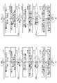
図1は、一実施形態に係る不具合箇所推定システムのシステム構成の例を示す図である。不具合箇所推定システム100は、例えば、1つ以上の空調機器111a、111b、・・・、空調システム110の不具合を検知する1つ以上のセンサ112a、112b、・・・、及びコントローラ113等を備える空調システム110を含む。なお、以下の説明において、1つ以上の空調機器111a、111b、・・・のうち、任意の空調機器を示す場合、「空調機器111」を用いる。また、1つ以上のセンサ112a、112b、・・・のうち、任意のセンサを示す場合、「センサ112」を用いる。 FIG. 1 is a diagram showing an example of the system configuration of a failure location estimation system according to one embodiment. , one or
好ましくは、不具合箇所推定システム100は、通信ネットワークN1、N2等を介して、コントローラ113、及びセンサ112等と通信可能な管理サーバ120を含む。ここで、通信ネットワークN1は、例えば、インターネットやLAN(Local Area Network)の通信ネットワークである。通信ネットワークN2は、空調システム110内で機器間の通信に用いられる、例えば、LAN等のネットワークである。ただし、通信ネットワークN2は、LANに限られず、空調システム110内で機器間の通信が可能な、様々な通信方式のネットワークであって良い。なお、以下の説明において、通信ネットワークN1、N2を特に区別する必要がない場合、単に「通信ネットワーク」と呼ぶ。 Preferably, the failure
空調機器111は、例えば、施設内の空気の温度、湿度、清浄度、又は気流等の空気環境を調整(調和)する機器である。空調機器111には、例えば、室内機、室外機、環境センサ、チラー(冷却水循環措置)、エアハンドリングユニット、配管、継手、又はダクト等の様々な構成要素が含まれ得る。また、空調機器111には、例えば、換気装置、及び換気装置用のダクト、吹出口、吸込口等の構成要素が含まれていても良い。 The air conditioner 111 is, for example, a device that adjusts (harmonizes) the air environment such as the temperature, humidity, cleanliness, or airflow of the air in the facility. The air conditioner 111 may include various components such as, for example, indoor units, outdoor units, environment sensors, chillers (cooling water circulation devices), air handling units, pipes, joints, or ducts. Further, the air conditioner 111 may include, for example, a ventilator, a duct for the ventilator, an air outlet, an air inlet, and other components.
センサ112は、空調システム110の不具合を検知する検知機器である。センサ112には、例えば、冷媒の漏れを検知する冷媒センサ(又はガスセンサ)、漏水を検知する漏水センサ、音を検知する音センサ(例えばマイク)、振動を検知する振動センサ、又はカメラ等の様々な検知機器が含まれ得る。 The sensor 112 is a detection device that detects malfunction of the
コントローラ(制御部)113は、コンピュータの構成を備え、所定のプログラムを実行することにより、1つ以上の空調機器111a、111b、・・・を制御する機器である。例えば、コントローラ113は、タッチパネルディスプレイ等に操作画面を表示して、管理者又は利用者等による操作に従って、施設内の温度、湿度、風量、又は清浄度等を制御する。なお、コントローラ113は、空調システム(冷凍空調システム)110を制御する制御部の一例である。本実施形態に係る制御部は、例えば、コンピュータ、プロセッサ、CPU(Central Processing Unit)、ASIC(application specific integrated circuit)、又はFPGA(Field Programmable Gate Array)等のハードウェアである。 The controller (control unit) 113 is a device that has a computer configuration and controls one or
また、本実施形態に係るコントローラ113は、空調システム110に含まれる1つ以上の空調機器111a、111b、・・・の構成要素が設置された位置を示す設置位置情報を、コントローラ113の記憶部、又は管理サーバ120等に記憶して管理している。さらに、コントローラ113は、1つ以上のセンサ112a、112b、・・・の固有情報を含むセンサ情報と、設置位置情報とを用いて、空調システム110で発生した不具合を検知し、不具合箇所の候補等を示す不具合情報を出力する機能を有している。 Further, the
なお、コントローラ113が備える、空調機器の制御、センサ情報の取得、設置位置情報の管理、及び不具合情報の出力等の機能のうち、少なくとも一部は、管理サーバが備えていても良い。 At least some of the functions of the
管理サーバ120は、コンピュータの構成を備えた情報処理装置、又は複数のコンピュータを含むシステムである。管理サーバ120は、例えば、複数の空調システム110を管理するクラウドシステム等であっても良い。 The
(設置位置情報について)
不具合箇所推定システム100(コントローラ113又は管理サーバ120)は、空調システム110に含まれる空調機器111の1つ以上の構成要素が設置された位置を示す設置位置情報を管理している。(About installation location information)
The failure point estimation system 100 (the
図2は、一実施形態に係る設置位置情報の一例のイメージを示す図である。設置位置情報には、一例として、図2に示すように、空調機器111が設置された部屋220、及び部屋220に設置された空調システム110の1つ以上の構成要素が設置された位置を記録した図面情報200が含まれる。図2の例では、図面情報200には、部屋220を上方から見た図に、室内機201a~201d、室内機に接続された配管(冷媒配管)203、及び配管203の接続部204a~204h等が設置された位置を示す情報が記録されている。また、図面情報200には、換気装置210、換気装置210に接続されたダクト211、複数の吹出口212、及び複数の吸込口213等の位置を示す情報が記録されている。さらに、図面情報200には、不具合を検知する1つ以上のセンサ112a、112b、及び室内機201a~201dの各々が備える環境センサ202a~202d等の位置を示す情報が記録されていても良い。 FIG. 2 is a diagram showing an image of an example of installation position information according to one embodiment. As an example, as shown in FIG. 2, the installation location information includes a
この図面情報200は、例えば、空調システム110を提供する提供者、又は空調システム110を管理する管理者等が、空調機器111を施工した際の設計図面、又は施工図面等に基づいて作成し、コントローラ113、又は管理サーバ120等に記憶しておく。或いは、不具合箇所推定システム100は、空調機器111を施工した際の設計図面、又は施工図面等を解析して、図面情報200を作成する機能を有していても良い。 The drawing
好ましくは、設置位置情報には、空調システム110に含まれる1つ以上の構成要素を識別する識別情報と、各構成要素が設置された位置を示す座標情報とを記憶した機器座標情報等が含まれる。 Preferably, the installation position information includes identification information for identifying one or more components included in the
(不具合情報について)
不具合箇所推定システム100は、例えば、不具合を検知するセンサ112a、112bのセンサ情報を取得し、不具合が検知された場合、取得したセンサ情報と設置位置情報とを用いて、不具合箇所の候補等を示す不具合情報を出力する。(About bug information)
For example, the defect
図3は、一実施形態に係る不具合情報の一例のイメージを示す図である。この図は、一例として、図2のセンサ112aで、配管203を通る冷媒の漏れ(以下、冷媒漏洩と呼ぶ)を検知した場合に、不具合箇所推定システム100が出力する不具合情報300の一例を示している。 FIG. 3 is a diagram showing an image of an example of defect information according to one embodiment. As an example, this figure shows an example of
不具合箇所推定システム100は、例えば、センサ112aで冷媒漏洩を検知した場合、センサ112aのセンサ情報に含まれる固有情報に基づいて、図2に示すような図面情報200上のセンサ112aの位置(座標情報)を特定する。また、不具合箇所推定システム100は、設置位置情報(例えば、図2の図面情報200等)を用いて、センサ112aから所定の範囲内にある、冷媒漏洩の不具合箇所の候補となる構成要素を抽出する。ここでは、不具合箇所の候補となる構成要素として、配管203の接続部204a、204b、204c、204dが抽出されるものとする。 For example, when the
この場合、不具合箇所推定システム100は、一例として、図3に示すように、不具合箇所の候補の位置を示す図301、不具合箇所の候補を示す文字列302、及び不具合の範囲を示す文字列303等を表示する不具合情報300を出力する。例えば、不具合箇所推定システム100は、図3に示すような不具合情報300を、コントローラ113等に表示しても良いし、予め登録された情報端末等に送信しても良い。 In this case, as an example, as shown in FIG. and the like is output. For example, the defect
図3に示すような不具合情報300により、空調システム110を管理する管理者、又は空調システム110を利用する利用者等は、配管203の接続部204a~204dのいずれかで冷媒漏洩が発生している可能性があることを容易に認識することができる。 The
図4は、一実施形態に係る不具合情報の別の一例を示す図である。この図は、一例として、図2のセンサ112a、112bで同時に、配管203を通る冷媒漏洩を検知した場合に、不具合箇所推定システム100が出力する不具合情報400の一例を示している。 FIG. 4 is a diagram illustrating another example of defect information according to one embodiment. As an example, this figure shows an example of
不具合箇所推定システム100は、例えば、センサ112a、112bで冷媒漏洩を検知した場合、センサ112のセンサ情報に含まれる固有情報に基づいて、図2に示すような図面情報200上のセンサ112a、112bの位置を特定する。また、不具合箇所推定システム100は、設置位置情報(例えば、図2の図面情報200)を用いて、センサ112a、112bから所定の範囲内にある、冷媒漏洩の不具合箇所の候補となる構成要素を抽出する。ここでは、不具合箇所の候補となる構成要素として、配管203の接続部204a~204hが抽出されるものとする。 For example, when the
この場合、不具合箇所推定システム100は、一例として、図4に示すように、不具合箇所の候補の位置を示す図401、不具合箇所の候補を示す文字列302、及び不具合の範囲を示す文字列303等を表示する不具合情報300を出力する。 In this case, as an example, as shown in FIG. 4, the defect
従来の技術では、このように、部屋220全体で冷媒漏洩が検知された場合、部屋220内で冷媒漏洩が発生したことが判るのみであり、不具合箇所の候補を示すことは困難である。 In the conventional technology, when refrigerant leakage is detected in the
一方、本実施形態に係る不具合箇所推定システム100では、冷媒漏洩を検知したセンサ112のセンサ情報と、設置位置情報とを用いて不具合箇所の候補を抽出し、例えば、図4に示すような不具合情報400を提供することができる。また、本実施形態に係る不具合箇所推定システム100は、センサ112aが不具合を検知した時刻と、センサ112bが不具合を検知した時間との時間差等に基づいて、不具合箇所の候補をさらに絞り込む機能を有している。なお、具体的な処理内容については、複数の実施形態を例示して後述する。 On the other hand, in the defect
このように、本実施形態によれば、複数の構成要素を含む冷凍空調システムにおいて、より少ないセンサの数で不具合が発生した箇所、不具合が発生した箇所の候補、又は不具合が発生した範囲等を特定できる。 As described above, according to the present embodiment, in a refrigeration and air-conditioning system including a plurality of components, a location where a problem has occurred, candidates for a location where a problem has occurred, or a range where a problem has occurred can be identified with a smaller number of sensors. can be identified.
<ハードウェア構成>
(コンロトーラ、及び管理サーバのハードウェア構成)
コントローラ113、及び管理サーバ120は、例えば、図5に示すようなコンピュータ500のハードウェア構成を有する。別の一例として、管理サーバ120は、例えば、複数のコンピュータ500によって構成される。<Hardware configuration>
(Hardware configuration of controller and management server)
The
図5は、一実施形態に係るコンピュータのハードウェア構成の例を示す図である。コンピュータ500は、例えば、CPU(Central Processing Unit)501、メモリ502、ストレージデバイス503、通信装置504、出力装置505、入力装置506、及びバス507等を有する。 FIG. 5 is a diagram illustrating an example of a hardware configuration of a computer according to one embodiment; The
CPU501は、例えば、ストレージデバイス503、又はメモリ502等の記録媒体に記憶した所定のプログラムを実行することにより、不具合箇所推定システム100が備える様々な機能を実現するプロセッサである。メモリ502は、例えば、CPU501のワークエリア等として用いられる揮発性のメモリであるRAM(Random Access Memory)、及びコンピュータ500の起動用のプログラム等を記憶する不揮発性のメモリであるROM(Read Only Memory)等を含む。ストレージデバイス503は、例えば、OS(Operating System)、アプリケーション等のプログラム、及び各種のデータ等を記憶する大容量の記憶装置であり、SSD(Solid State Drive)、又はHDD(Hard Disk Drive)等によって実現される。 The
通信装置504は、コンピュータ500を通信ネットワークに接続し、他の装置と通信する、例えば、LAN、WAN(Wide Area Network)等の通信インタフェースである。出力装置505は、例えば、不具合情報、操作画面等の様々な表示画面を表示する表示デバイス、又は音声メッセージ、エラー音等を出力する音声出力デバイス等を含む。入力装置506は、例えば、タッチパネル、キーボード、又はポインティングデバイス等の入力を受け付ける入力デバイスである。なお、入力装置506は、例えば、タッチパネルディスプレイ等の表示入力装置であっても良い。バス507は、上記の各構成要素に接続され、例えば、アドレス信号、データ信号、及び各種の制御信号等を伝送する。 The
(空調機器、及びセンサのハードウェア構成)
空調機器111、及びセンサ112は、例えば、コンピュータの構成と、通信装置とを備える公知の空調機器111、及びセンサ112を利用することを想定しているため、ここでは詳細な説明は省略する。(Hardware configuration of air conditioning equipment and sensors)
The air conditioning equipment 111 and the sensor 112 are assumed to use, for example, a known air conditioning equipment 111 and sensor 112 having a computer configuration and a communication device, so detailed description thereof will be omitted here.
<機能構成>
図6は、一実施形態に係る不具合箇所推定システムの機能構成の例を示す図である。不具合箇所推定システム100は、例えば、通信部601、取得部602、出力部603、操作受付部604、センサ情報記憶部605、及び設置位置情報記憶部606等を有する。<Functional configuration>
FIG. 6 is a diagram illustrating an example of the functional configuration of a failure location estimation system according to one embodiment. The fault
通信部601、取得部602、出力部603、及び操作受付部604は、例えば、不具合箇所推定システム100が備えるコンピュータ500(コントローラ113及び/又は管理サーバ120)によって実行されるプログラムによって実現される。なお、上記の機能構成のうち、少なくとも一部は、ハードウェアによって実現されるものであっても良い。また、センサ情報記憶部605、及び設置位置情報記憶部606は、例えば、不具合箇所推定システム100が備えるコンピュータ500のストレージデバイス503、又はメモリ502等によって実現される。 The
通信部601は、不具合箇所推定システム100を、例えば、図5の通信装置504等を用いて、通信ネットワークに接続し、他の装置と通信する通信処理を実行する。 The
取得部602は、空調システム(冷凍空調システムの一例)110で発生した不具合を検知する1つ以上のセンサ112a、112b、・・・の固有情報を含むセンサ情報を、例えば、通信部601を介して取得する取得処理を実行する。
図7(A)は、センサ112が出力するセンサ情報の一例のイメージを示している。図7(A)の例では、センサ情報701には、センサ112を識別するための識別情報である管理ID(固有情報の一例)と、1つ以上のセンサデータ(センサデータ1、センサデータ2、・・・)が含まれる。管理IDは、不具合箇所推定システム100が付与した識別情報であっても良いし、例えば、センサ112のアドレス情報(IPアドレス、又はMACアドレス)等の他の固有情報であっても良い。センサデータは、センサ112が取得した、例えば、フロン濃度データ、温度データ、湿度データ、音データ、振動データ、又は画像データ等の検知データである。 FIG. 7A shows an image of an example of sensor information output by the sensor 112. FIG. In the example of FIG. 7A, the
この場合、不具合箇所推定システム100は、センサ情報記憶部605等に、例えば、図7(B)に示すようなセンサ位置情報702を予め記憶しておく。センサ位置情報702には、複数のセンサ112の管理IDと、各センサ112が設置された位置を示す位置座標とが記憶されている。これにより、不具合箇所推定システム100は、センサ112が出力するセンサ情報701に含まれる管理IDと、センサ位置情報702とを用いて、センサ情報701を出力したセンサ112の位置を特定することができる。 In this case, the fault
図7(C)は、センサ112が出力するセンサ情報の別の一例のイメージを示している。図7(C)の例では、センサ情報703には、図7(A)に示したセンサ情報701に加えて、位置座標が含まれる。このように、センサ112が出力するセンサ情報には、位置座標(センサ112が設置された位置に関する情報の一例)が含まれていても良い。 FIG. 7C shows an image of another example of sensor information output by the sensor 112 . In the example of FIG. 7C, the
図7(D)は、センサ情報記憶部605に記憶するセンサ情報704の一例のイメージを示している。センサ情報704には、複数のセンサ112から取得したセンサ情報に含まれる管理ID、位置座標、1つ以上のセンサデータ、及び検知時刻等の情報が含まれる。検知時刻の情報は、センサ112が出力するセンサ情報に含まれている時刻を用いても良いし、取得部602が、センサ112から取得したセンサ情報を、センサ情報704に記憶する際に付与しても良い。 FIG. 7D shows an example image of
なお、コントローラ113が取得部602を有している場合、取得部602は、図7(D)に示すようなセンサ情報704を、センサ情報を収集する管理サーバ120から取得して、コントローラ113が備えるセンサ情報記憶部605に記憶しても良い。要するに、取得部602は、図7(D)に示すようなセンサ情報704をセンサ情報記憶部605に記憶するものであれば、取得するセンサ情報の形式は任意の形式であって良い。 Note that when the
出力部603は、取得部602が取得したセンサ情報704と、設置位置情報記憶部606に記憶した設置位置情報とに基づいて、不具合が発生した箇所、不具合が発生した箇所の候補、又は不具合が発生した範囲を示す不具合情報を出力する出力処理を実行する。出力部603は、例えば、推定部611、表示制御部612、及び音声制御部613等を含む。 Based on the
推定部611は、取得部602が取得したセンサ情報と、空調システム110に含まれる1つ以上の構成要素が設置された位置を示す設置位置情報とを用いて、不具合が発生したときに、不具合が発生した箇所の候補等を推定(抽出)する。 The estimating
図8(A)は、設置位置情報に含まれる図面情報801の一例のイメージを示している。図面情報801には、図2で説明した図面情報200と同様に、部屋220に設置された空調システム110の1つ以上の構成要素が設置された位置が記録されている。図8(A)の例では、図面情報801には、部屋220を上方から見た図に、室内機201a~201d、室内機に接続された配管(冷媒配管)203、及び配管203の接続部204a~204h等の位置を示す情報が記録されている。また、図面情報801には、換気装置210、換気装置210に接続されたダクト211a~211d、吹出口212a~212d、及び吸込口213a~213d等の位置を示す情報も記録されている。さらに、図面情報801には、不具合を検知する1つ以上のセンサ112a、112b、及び室内機201a~201dの各々が備える環境センサ202a~202d等の位置を示す情報が記録されていても良い。 FIG. 8A shows an image of an example of drawing
図8(B)は、設置位置情報に含まれる機器座標情報802の一例のイメージを示している。機器座標情報802には、空調システム110に含まれる1つ以上の構成要素を識別する管理IDと、各構成要素の表示名、及び各構成要素が設置された位置を示す座標情報等が記録されている。管理IDは、各構成要素を識別する識別情報である。表示名は、例えば、不具合情報に表示するとき等に用いられる各構成要素の名称等を示す情報である。位置座標は、例えば、空調機器111を施工した際の設計図面、施工図面等、又は図面情報801等に基づいて取得した、構成要素の位置を示す座標である。位置座標は、一例として、図面情報801上の座標で表される。別の一例として、位置座標は、施設内の位置情報システム等により測位した3次元の位置情報等であっても良い。なお、図面情報801、及び機器座標情報802は、設置位置情報の一例である。 FIG. 8B shows an image of an example of device coordinate
推定部611は、例えば、1つのセンサ112が不具合を検知した場合、不具合を検知したセンサ112から所定の距離以内にある所定の構成要素を、不具合箇所の候補とする。 For example, when one sensor 112 detects a defect, the estimating
好ましくは、不具合箇所推定システム100は、不具合を検知したセンサ112の種類に応じて、当該不具合が発生する可能性がある所定の構成要素が予め定められている。例えば、冷媒漏洩の不具合が、配管203の接続部で発生することが予め判っている場合、配管203の接続部が、冷媒センサに対応する所定の構成要素となる。 Preferably, in the failure
また、推定部611は、複数のセンサ112が不具合を検知した場合、不具合を検知した全てのセンサ112から所定の距離以内にある所定の構成要素を、不具合箇所の候補とする。なお、推定部611の処理は、様々な変形や応用が可能なので、具体的な処理内容については、複数の実施形態を例示して後述する。 In addition, when a plurality of sensors 112 detect a defect, the estimating
表示制御部612は、例えば、推定部611が抽出した不具合箇所の候補を示す不具合情報(表示画面)を作成し、例えば、コントローラ113、管理サーバ120、又は管理サーバ120に接続する情報端末等の表示部に、作成した不具合情報を表示させる。図3、4で説明した不具合情報300、400は、表示制御部612が作成し、表示させる不具合情報の一例である。 The
音声制御部613は、例えば、表示制御部612が作成した不具合情報に音声(音声メッセージ、エラー音等)が含まれている場合、音声を出力する。また、別の一例として、音声制御部613は、推定部611が抽出した不具合箇所の候補を示す不具合情報(音声メッセージ、エラー音等)を作成し、例えば、コントローラ113、管理サーバ120、又は管理サーバ120に接続する情報端末等から、作成した不具合情報を出力しても良い。 For example, if the trouble information created by the
なお、図6に示す出力部603の機能構成は一例である。例えば、推定部611、表示制御部612、及び音声制御部613の機能は、1つの出力部603で実現されるものであっても良い。 Note that the functional configuration of the
操作受付部604は、例えば、図5の入力装置506等を用いて、管理者、又は利用者による各種の操作を受け付ける。センサ情報記憶部605は、例えば、図7(D)に示すようなセンサ情報704を記憶する。設置位置情報記憶部606は、例えば、図8(A)に示すような図面情報801、及び図8(B)に示すような機器座標情報802等を含む設置位置情報を記憶する。 The
なお、図6に示す不具合箇所推定システム100に含まれる各機能構成は、図1のコントローラ113に含まれていても良いし、管理サーバ120に含まれていても良い。また、不具合箇所推定システム100に含まれる各機能構成は、コントローラ113と管理サーバ120とに分散して設けられていても良い。ここでは、コントローラ113が、図6に示す不具合箇所推定システム100の機能構成を有しているものとして、以下の説明を行う。 6 may be included in the
<処理の流れ>
続いて、本実施形態に係る不具合箇所推定方法の処理の流れについて説明する。<Process flow>
Next, the flow of processing of the defect location estimation method according to the present embodiment will be described.
[第1の実施形態]
図9(A)は、第1の実施形態に係る不具合箇所推定処理の例を示すフローチャートである。この処理は、例えば、図8(A)に示すような部屋220に、不具合を検知するセンサ112が1つ、部屋220全体をカバーするように設けられている場合に、不具合箇所推定システム100のコントローラ(制御部)113が実行する処理の一例を示している。[First embodiment]
FIG. 9A is a flow chart showing an example of defect location estimation processing according to the first embodiment. For example, in a
ステップS901において、出力部603の取得部602は、部屋220に設けられた不具合を検知するセンサ112のセンサ情報を取得する。 In step S<b>901 , the
ステップS902において、取得部602は、取得したセンサ情報に基づいて、不具合が検知されたか否かを判定する。例えば、取得部602は、センサ情報に含まれるセンサデータの値が、予め定められた閾値を超えた場合、不具合が検知されたと判定する。 In step S902, the
ステップS903において、不具合が検知された場合、取得部602は、処理をステップS904に移行させる。一方、不具合が検知されていない場合、取得部602は、処理をステップS901に戻す。 If a problem is detected in step S903, the
ステップS904に移行すると、出力部603の推定部611は、取得部602が取得したセンサ情報と、設置位置情報記憶部606に記憶した位置情報とから、不具合が発生した可能性がある構成要素である不具合箇所の候補を抽出(推定)する。 When the process proceeds to step S904, the
好ましくは、推定部611は、例えば、図8(A)に示すような図面情報801、又は図8(B)に示すような機器座標情報802から、センサ112が検知した不具合に対応する所定の構成要素を抽出する。 Preferably, the estimating
ステップS905において、出力部603は、推定部611が抽出した不具合箇所の候補(構成要素)を示す不具合情報を作成し、出力する。なお、推定部611が抽出した所定の構成要素が1つである場合、出力部603は、推定部611が抽出した構成要素を、「不具合箇所」とする不具合情報を作成しても良い。また、不具合情報には、「不具合の範囲」として、センサ112が設置された部屋220の情報等が含まれていても良い。 In step S<b>905 , the
このとき、出力部603は、例えば、表示制御部612を用いて不具合情報(表示画面)を作成し、コントローラ113、又は管理サーバ120等の表示部に表示させる。或いは、出力部603は、音声制御部613を用いて、不具合情報(音声メッセージ、エラー音等)を作成し、コントローラ113、又は管理サーバ120等から出力させても良い。さらに、出力部603は、不具合情報(表示画面、音声メッセージ、エラー音等)を、予め登録された管理者用の情報端末等に送信しても良い。 At this time, for example, the
図9(B)は、第1の実施形態に係る不具合箇所推定処理の具体的な一例を示すフローチャートである。この処理は、例えば、図8(A)に示した部屋220に設けられたセンサ112が、冷媒漏洩を検知するフロンセンサである場合の処理の例を示している。 FIG. 9B is a flow chart showing a specific example of the defect location estimation process according to the first embodiment. This processing shows an example of processing when the sensor 112 provided in the
ステップS911において、出力部603の取得部602は、部屋220に設けられたフロンセンサであるセンサ112のセンサ情報を取得する。 In step S<b>911 , the
ステップS912において、取得部602は、取得したセンサ情報に基づいて、冷媒漏洩の有無を判定する。例えば、取得部602は、センサ情報に含まれるフロン濃度の値が、予め定められた閾値より大きい場合、冷媒漏洩が検知されたと判定する。 In step S912, the acquiring
ステップS913において、冷媒漏洩が検知された場合、取得部602は、処理をステップS914に移行させる。一方、冷媒漏洩が検知されていない場合、取得部602は、処理をステップS911に戻す。 In step S913, when coolant leakage is detected, the
ステップS914に移行すると、出力部603の推定部611は、取得部602が取得したセンサ情報と、設置位置情報記憶部606に記憶した位置情報とから、冷媒漏洩箇所の候補となる配管203の接続部204a~204hを抽出する。なお、配管203の接続部は、フロンセンサであるセンサ112に対応する所定の構成要素の一例である。 In step S914, the estimating
ステップS915において、出力部603の表示制御部612は、推定部611が抽出した配管203の接続部204a~204hを図示する不具合情報を作成し、例えば、コントローラ113、又は管理サーバ120の表示部等に表示させる。 In step S915, the
図10は、ステップS915において、表示制御部612が表示させる不具合情報の一例のイメージを示している。図10の例では、不具合情報400には、冷媒漏洩箇所の候補の位置を示す図1001、冷媒漏洩箇所の候補を示す文字列1002、及び冷媒漏洩の範囲を示す文字列1003等が表示されている。 FIG. 10 shows an image of an example of defect information displayed by the
従来の技術では、このような場合、部屋220内で冷媒漏洩が発生したことしか示すことができない。しかし、本実施形態に係る不具合箇所推定システム100では、設置位置情報を用いて冷媒漏洩箇所の候補を抽出し、例えば、図10に示すような不具合情報1000を提供することができる。 In such a case, the conventional technology can only indicate that a refrigerant leak has occurred within the
[第2の実施形態]
図11(A)は、第2の実施形態に係る不具合箇所推定処理の例を示すフローチャートである。この処理は、例えば、図8(A)に示すような部屋220に、不具合を検知するセンサ112が複数設けられている場合に、不具合箇所推定システム100のコントロ-ラ(制御部)113が実行する処理の一例を示している。なお、ここでは、第1の実施形態と同様の処理に対する詳細な説明は省略する。[Second embodiment]
FIG. 11A is a flow chart showing an example of defect location estimation processing according to the second embodiment. This process is executed by the controller (control unit) 113 of the fault
ステップS1101において、出力部603の取得部602は、部屋220に設けられた複数のセンサ112のセンサ情報を取得する。例えば、取得部602は、図7(D)に示すようなセンサ情報704から、更新されたセンサ情報、又は直近の所定の期間内のセンサ情報等を取得する。 In step S<b>1101 , the
ステップS1102において、取得部602は、取得したセンサ情報の各々で、不具合が検知されたか否かを判定する。例えば、取得部602は、センサ情報に含まれるセンサデータの値が、予め定められた閾値を超えた場合、不具合が検知されたと判定する。 In step S<b>1102 , the
ステップS1103において、不具合が検知されたセンサ情報がある場合、取得部602は、処理をステップS1104に移行させる。一方、不具合が検知されたセンサ情報がない場合、取得部602は、処理をステップS1101に戻す。 In step S<b>1103 , if there is sensor information in which a problem has been detected, the
ステップS1104に移行すると、出力部603の推定部611は、取得部602が取得したセンサ情報から、不具合を検知した1つ以上のセンサ112の位置座標を取得する。また、ステップS1105において、推定部611は、取得した位置座標から所定の距離以内にある所定の構成要素を抽出する。 In step S<b>1104 , the
ステップS1106において、複数のセンサ112が不具合を検知した場合、推定部611は、処理をステップS1107に移行させる。一方、1つのセンサ112が不具合を検知した場合、推定部611は、処理をステップS1108に移行させる。 In step S1106, when the plurality of sensors 112 detect a defect, the
ステップS1107に移行すると、推定部611は、不具合を検知した全てのセンサ112から、所定の距離以内にある所定の構成要素を抽出する。 After moving to step S1107, the
ステップS1108に移行すると、出力部603は、推定部611が抽出した構成要素を、不具合箇所の候補として示す不具合情報を作成し、出力する。なお、推定部611が抽出した所定の構成要素が1つである場合、出力部603は、推定部611が抽出した構成要素を、「不具合箇所」とした不具合情報を作成しても良い。また、不具合情報には、「不具合の範囲」を示す情報が含まれていても良い。 When the process proceeds to step S1108, the
図11(B)は、第2の実施形態に係る不具合箇所推定処理の具体的な一例を示すフローチャートである。この処理は、例えば、図8(A)に示すような部屋220に設けられたセンサ112a、112bが、冷媒漏洩を検知するフロンセンサである場合の処理の例を示している。なお、冷媒漏洩を検知するセンサ112の数は、3つ以上であっても良い。 FIG. 11B is a flow chart showing a specific example of the defect location estimation process according to the second embodiment. This processing shows an example of processing when the
ステップS1111において、出力部603の取得部602は、部屋220に設けられた複数のフロンセンサであるセンサ112のセンサ情報を取得する。例えば、取得部602は、図7(D)に示すようなセンサ情報704から、更新されたセンサ情報、又は直近の所定の期間内のセンサ情報等を取得する。 In step S<b>1111 , the
ステップS1112において、取得部602は、取得したセンサ情報の各々で、冷媒漏洩が検知されたか否かを判定する。例えば、取得部602は、センサ情報に含まれるフロン濃度の値が閾値を超えた場合、冷媒漏洩が検知されたと判定する。 In step S1112, the acquiring
ステップS1113において、冷媒漏洩が検知されたセンサ情報がある場合、取得部602は、処理をステップS1114に移行させる。一方、冷媒漏洩が検知されたセンサ情報がない場合、取得部602は、処理をステップS1111に戻す。 In step S1113, if there is sensor information indicating that refrigerant leakage has been detected, the
ステップS1114に移行すると、出力部603の推定部611は、取得部602が取得したセンサ情報から、冷媒漏洩を検知した1つ以上のセンサ(フロンセンサ)112の位置座標を取得する。また、ステップS1115において、推定部611は、取得した位置座標から所定の距離以内にある配管(冷媒配管)203の接続部を抽出する。なお、配管203の接続部は、センサ(フロンセンサ)112に対応する所定の構成要素の一例である。 After proceeding to step S1114, the
ステップS1116において、複数のセンサ(フロンセンサ)112が冷媒漏洩を検知した場合、推定部611は、処理をステップS1117に移行させる。一方、1つのセンサ112が冷媒漏洩を検知した場合、推定部611は、処理をステップS1118に移行させる。 In step S1116, when the plurality of sensors (fluorocarbon sensors) 112 detect refrigerant leakage, the
ステップS1117に移行すると、推定部611は、冷媒漏洩を検知した全てのセンサ(フロンセンサ)112から、所定の距離以内にある配管203の接続部を抽出する。 After proceeding to step S1117, the estimating
ステップS1118に移行すると、出力部603は、推定部611が抽出した配管203の接続部を、冷媒漏洩箇所の候補として示す不具合情報を作成し、出力する。例えば、図8(A)に示すような部屋220のセンサ112aで冷媒漏洩が検知された場合、出力部603は、図3に示すような不具合情報300を出力する。 When the process proceeds to step S1118, the
このように、不具合箇所推定システム100は、複数のセンサ112を用いて、不具合が発生した箇所の候補を絞り込み、不具合情報の精度を向上させることができる。 In this way, the failure
上記の例では、冷媒漏洩を検知するセンサ112をフロンセンサとしたが、これに限られず、冷媒漏洩を検知可能な様々なガスセンサを、センサ112として適用することができる。 In the above example, the sensor 112 for detecting refrigerant leakage is a Freon sensor, but the sensor 112 is not limited to this, and various gas sensors capable of detecting refrigerant leakage can be applied.
[第3の実施形態]
第1、2の実施形態では、不具合を検知するセンサ112がフロンセンサ、又はガスセンサである場合の例について説明した。第3の実施形態では、不具合を検知するセンサ112が、音データを取得するマイク等の音センサ、又は振動を検知する振動センサである場合の例について説明する。なお、ここでは、第1、2の実施形態と同様の処理に対する詳細な説明は省略する。[Third Embodiment]
In the first and second embodiments, an example in which the sensor 112 that detects a problem is a Freon sensor or a gas sensor has been described. In the third embodiment, an example will be described in which the sensor 112 that detects malfunction is a sound sensor such as a microphone that acquires sound data or a vibration sensor that detects vibration. A detailed description of the same processing as in the first and second embodiments will be omitted here.
図12(A)は、第3の実施形態に係る不具合箇所推定処理の一例を示すフローチャートである。この処理は、不具合を検知するセンサ112が、音データを取得するマイク等の音センサである場合に、不具合箇所推定システム100のコントローラ(制御部)113が実行する処理の例を示している。 FIG. 12A is a flow chart showing an example of defect point estimation processing according to the third embodiment. This processing shows an example of processing executed by the controller (control unit) 113 of the fault
ステップS1201において、出力部603の取得部602は、部屋220に設けられた複数の音センサのセンサ情報を取得し、センサ情報に含まれる音データを取得する。例えば、取得部602は、図7(D)に示すようなセンサ情報704から、更新されたセンサ情報、又は直近の所定の期間内のセンサ情報等を取得する。 In step S1201, the
ステップS1202において、取得部602は、取得した音データの各々で、不具合判定を行う。例えば、取得部602は、音データが、音の大きさが閾値1より大きい音を含み、かつ閾値1より大きい音の周波数が、閾値2より高く、閾値3より低い場合、不具合を検知したと判定する。なお、閾値1~3は、不具合が発生したときに発生する、或いは発生すると予測される音の大きさ、及び音の周波数等に基づいて、予め設定されているものとする。 In step S1202, the acquiring
ステップS1203において、不具合が検知された音データがある場合、取得部602は、処理をステップS1204に移行させる。一方、不具合が検知された音データがない場合、取得部602は、処理をステップS1201に戻す。 In step S1203, if there is sound data for which a problem has been detected, the
ステップS1204に移行すると、出力部603の推定部611は、取得部602が取得したセンサ情報から、不具合を検知した音データを取得した、1つ以上の音センサの位置座標を取得する。 In step S<b>1204 , the
ステップS1205において、推定部611は、取得した位置座標から所定の距離以内にある、音センサに対応する所定の構成要素を抽出する。なお、音センサに対応する所定の構成要素には、例えば、室内機、チラー、室外機等の機器、又は配管、ダクト、継手(配管又はダクトの接続部)等が含まれ得る。 In step S1205, the
ステップS1206において、複数の音センサが不具合を検知した場合、推定部611は、処理をステップS1207に移行させる。一方、1つの音センサが不具合を検知した場合、推定部611は、処理をステップS1208に移行させる。 In step S1206, when a plurality of sound sensors detect a malfunction, the
ステップS1207に移行すると、推定部611は、不具合を検知した全ての音センサから、所定の距離以内にある所定の構成要素を抽出する。 After proceeding to step S1207, the
ステップS1208に移行すると、出力部603は、推定部611が抽出した所定の構成要素を、不具合箇所の候補として示す不具合情報を作成し、出力する。 When the process proceeds to step S1208, the
上記の処理により、不具合箇所推定システム100は、例えば、機器の故障(例えば、機器内のモータの故障等)、又は機器及び配管のがたつき等、冷媒漏洩以外の不具合箇所の候補を示す不具合情報を出力することができる。 With the above-described processing, the failure
図12(B)は、第3の実施形態に係る不具合箇所推定処理の別の一例を示すフローチャートである。この処理は、不具合を検知するセンサ112が、振動を検知する振動センサである場合に、不具合箇所推定システム100のコントローラ(制御部)113が実行する処理の例を示している。 FIG. 12B is a flow chart showing another example of the defect point estimation process according to the third embodiment. This processing shows an example of processing executed by the controller (control unit) 113 of the fault
ステップS1211において、出力部603の取得部602は、部屋220に設けられた複数の振動センサのセンサ情報を取得し、センサ情報に含まれる振動データを取得する。例えば、取得部602は、図7(D)に示すようなセンサ情報704から、更新されたセンサ情報、又は直近の所定の期間内のセンサ情報等を取得する。 In step S1211, the
ステップS1212において、取得部602は、取得した振動データの各々で、不具合判定を行う。例えば、取得部602は、振動データが、振動の大きさが閾値Aより大きい振動を含み、かつ閾値Aより大きい振動の周波数が、閾値Bより高く、閾値Cより低い場合、不具合を検知したと判定する。なお、閾値A~Cは、不具合が発生したときに発生する、或いは発生すると予測される振動の大きさ、及び振動の周波数等に基づいて、予め設定されているものとする。 In step S<b>1212 , the
ステップS1213において、不具合が検知された振動データがある場合、取得部602は、処理をステップS1214に移行させる。一方、不具合が検知された振動データがない場合、取得部602は、処理をステップS1211に戻す。 In step S1213, if there is vibration data in which a problem has been detected, the
ステップS1214に移行すると、出力部603の推定部611は、取得部602が取得したセンサ情報から、不具合を検知した振動データを取得した、1つ以上の振動センサの位置座標を取得する。 In step S<b>1214 , the
ステップS1215において、推定部611は、取得した位置座標から所定の距離以内にある、振動センサに対応する所定の構成要素を抽出する。なお、振動センサに対応する所定の構成要素には、例えば、室内機、チラー、室外機等の機器等が含まれ得る。 In step S1215, the
ステップS1216において、複数の振動センサが不具合を検知した場合、推定部611は、処理をステップS1217に移行させる。一方、1つの振動センサが不具合を検知した場合、推定部611は、処理をステップS1218に移行させる。 In step S1216, when a plurality of vibration sensors detect a malfunction, the
ステップS1217に移行すると、推定部611は、不具合を検知した全ての振動センサから、所定の距離以内にある所定の構成要素を抽出する。 After proceeding to step S1217, the
ステップS1218に移行すると、出力部603は、推定部611が抽出した所定の構成要素を、不具合箇所の候補として示す不具合情報を作成し、出力する。 When the process proceeds to step S1218, the
上記の処理により、不具合箇所推定システム100は、例えば、機器の故障等、冷媒漏洩以外の不具合箇所の候補を示す不具合情報を提供することができる。 Through the above-described processing, the fault
(所定の距離について)
図13は、第2、3の実施形態に係る所定の距離について説明するための図である。(Regarding a given distance)
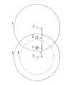
FIG. 13 is a diagram for explaining the predetermined distance according to the second and third embodiments.
例えば、図11(B)のステップS1117において、出力部603の推定部611は、冷媒漏洩を検知した全てのフロンセンサから所定の距離以内にある所定の構成要素を抽出している。この所定の距離は、初期値として、例えば、過去のデータ等から予測したフロンセンサの検知範囲、又はシミュレーション等で予測したフロンセンサの検知範囲等を適用することができる。また、この所定の距離は、必要に応じて動的に変更することができる。 For example, in step S1117 of FIG. 11B, the
例えば、図13において、2つのセンサ112x、112yがフロンセンサであり、2つのセンサ112x、112yの間に、冷媒漏洩箇所の候補となる2つの構成要素1301、1302があるものとする。また、2つの構成要素1301、1302のうち、構成要素1301で冷媒漏洩が発生しており、構成要素1301とセンサ112xとの間の距離がd1、構成要素1301とセンサ112yとの間の距離がd2(d1<d2)であるものとする。さらに、センサ112xから所定の距離(初期値)以内の検知範囲1303と、センサ112yから所定の距離(初期値)以内の検知範囲1304に、構成要素1301、1302が含まれるものとする。 For example, in FIG. 13, it is assumed that two
この場合、構成要素1301から漏洩した冷媒が拡散して、センサ112xで検知されるまでの時間(第1の時間)と、センサ112yで検知されるまでの時間(第2の時間)との間には時間差がある。推定部611は、この時間差を利用して、冷媒漏洩箇所の候補を抽出する所定の距離を変更して、冷媒漏洩箇所の候補を抽出する検知範囲1305を限定しても良い。 In this case, the time (first time) until the coolant leaking from the
例えば、推定部611は、距離と検知時間とが比例すると仮定して、第1の時間と第2の時間との時間差から、距離d1と距離d2との比を求め、この比に応じて、所定の距離を短くし、より狭い検知範囲1305で、冷媒漏洩箇所の候補を抽出しても良い。これにより、推定部611は、冷媒漏洩箇所の候補を、構成要素1301に絞り込むことができる。 For example, the
なお、距離と検知時間との関係については、例えば、冷媒の拡散速度と時間等に基づいて、距離を算出する関数等を作成しても良いし、学習済みの予測モデル等を利用しても良い。 Regarding the relationship between the distance and the detection time, for example, a function for calculating the distance may be created based on the diffusion speed and time of the refrigerant, or a learned prediction model may be used. good.
別の一例として、図12(A)のステップS1207において、出力部603の推定部611は、不具合を検知した全ての音センサから所定の距離以内にある所定の構成要素を抽出している。この所定の距離も、必要に応じて動的に変更することができる。 As another example, in step S1207 of FIG. 12A, the
例えば、図13において、2つのセンサ112x、112yが音センサであり、2つのセンサ112x、112yの間に、不具合箇所の候補となる2つの構成要素1301、1302があるものとする。また、2つの構成要素1301、1302のうち、構成要素1301で不具合による異音が発生しており、構成要素1301とセンサ112xとの間の距離がd1、構成要素1301とセンサ112yとの間の距離がd2(d1<d2)であるものとする。 For example, in FIG. 13, it is assumed that two
この場合、構成要素1301から発生した異音を、センサ112xで検知した音の大きさ(第1の音圧)と、センサ112yで検知した音の大きさ(第2の音圧)とには差がある。推定部611は、この第1の音圧と第2の音圧との差を利用して、不具合箇所の候補を抽出する所定の距離を変更して、不具合箇所の候補を抽出する検知範囲1305を限定しても良い。 In this case, for the abnormal noise generated from the
例えば、推定部611は、距離と音の大きさ(音圧)とが比例すると仮定して、第1の音圧と第2の音圧との差から、距離d1と距離d2との比を求め、この比に応じて、所定の距離を短くし、より狭い検知範囲1305で、不具合箇所の候補を抽出しても良い。これにより、推定部611は、不具合箇所の候補を、構成要素1301に絞り込むことができる。なお、この方法は、センサ112x、112yが振動センサである場合にも適用することができる。 For example, the estimating
なお、距離と音の大きさ(又は振動の大きさ)との関係については、例えば、音の大きさ(又は振動の大きさ)に基づいて距離を算出する関数等を作成しても良いし、学習済みの予測モデル等を利用しても良い。 Regarding the relationship between the distance and the loudness of the sound (or the magnitude of the vibration), for example, a function for calculating the distance based on the loudness of the sound (or the magnitude of the vibration) may be created. , a trained prediction model or the like may be used.
[第4の実施形態]
第4の実施形態では、推定部611が、不具合を検知する1つ以上のセンサ112a、112b、・・・のセンサ情報に加えて、例えば、温度、湿度等を検知する環境センサのセンサ情報を用いて、不具合箇所の候補の推定精度を向上させる場合の例について説明する。[Fourth embodiment]
In the fourth embodiment, the
図14は、第4の実施形態に係る不具合箇所推定処理の例を示すフローチャートである。なお、図14に示す処理のうち、ステップS1111~1114、S1115~S1118の処理は、図11(B)で説明した第2の実施形態に係る不具合箇所推定処理と同様なので、ここでは第2の実施形態との相違点を中心に説明する。 FIG. 14 is a flow chart showing an example of defect location estimation processing according to the fourth embodiment. Of the processes shown in FIG. 14, the processes of steps S1111 to 1114 and S1115 to S1118 are the same as the defect location estimation process according to the second embodiment described with reference to FIG. The description will focus on differences from the embodiment.
ステップS1113で冷媒漏洩が検知された場合、出力部603の推定部611は、ステップS1401において、例えば、図8(A)の1つ以上の環境センサ202a~202dから、温度情報、湿度情報等を含むセンサ情報を取得する。例えば、推定部611は、取得部602を用いて、環境センサ202a~202dのうち、1つ以上の環境センサからセンサ情報を取得する。なお、ステップS1401の処理は、ステップS1114の前に実行しても良い。 When refrigerant leakage is detected in step S1113, the
ステップS1402において、推定部611は、取得した環境情報に基づいて、冷媒漏洩を検知した1つ以上のセンサの所定の距離を決定する。例えば、推定部611は、図13で説明したように、2つのセンサ112x、112yが冷媒漏洩を検知した場合、距離d1と距離d2との比を求め、この比に応じて、例えば、センサ112xの所定の距離を決定する。 In step S1402, the
このとき、推定部611は、前述したように、冷媒の拡散速度と時間とに基づいて距離を算出する関数、又は学習済みの予測モデル等を用いても良い。ここで、冷媒の拡散速度は、温度に依存するので、例えば、環境センサから取得した温度を用いて冷媒の拡散速度を求めることにより、距離の算出精度を向上させることができる。また、学習済みの予測モデルについても、温度情報を学習データの一つとして学習済みの予測モデルに、温度を入力することにより、距離の予測精度を向上させることができる。 At this time, as described above, the
ステップS1115において、推定部611は、ステップS1402で決定した所定の距離を用いて、取得した位置情報から所定の距離以内にある冷媒配管の接続部を抽出する。 In step S1115, the estimating
上記の処理により、不具合箇所推定システム100は、環境センサが取得した環境情報を用いて、不具合箇所の推定精度を向上させることができる。 By the above processing, the failure
[第5の実施形態]
第5の実施形態では、不具合を検知するセンサ112がカメラである場合の例について説明する。[Fifth Embodiment]
In the fifth embodiment, an example in which the sensor 112 that detects malfunction is a camera will be described.
図15は、第5の実施形態に係る不具合箇所推定処理の例を示すフローチャートである。ここでは、不具合を検知するセンサ112が、物体の温度を示す温度画像を撮影するサーモグラフィカメラ(以下、サーモカメラと呼ぶ)等のカメラであるものとする。サーモカメラは、測定対象物からの赤外線放射を画像化して温度に換算し、温度の分布を色等によって可視化する装置である。 FIG. 15 is a flow chart showing an example of defect location estimation processing according to the fifth embodiment. Here, it is assumed that the sensor 112 that detects the defect is a camera such as a thermography camera (hereinafter referred to as a thermo camera) that captures a temperature image showing the temperature of an object. A thermo-camera is a device that visualizes the infrared radiation emitted from an object to be measured, converts it into temperature, and visualizes the distribution of the temperature using colors or the like.
ステップS1501において、出力部603の取得部602は、複数のカメラのセンサ情報から、温度画像を取得する。一例として、取得部602は、図16に示すように部屋1610に設けられたカメラ1、カメラ2が撮影した温度画像を取得する。 In step S1501, the
ステップS1502において、取得部602は、取得した温度画像の各々で、不具合が検知されたか否かを判定する。例えば、取得部602は、温度画像に、閾値より高い温度の示すエリアがある場合、不具合が検知されたと判定する。 In step S1502, the acquiring
ステップS1503において、不具合が検知された温度画像がある場合、取得部602は、処理をステップS1504に移行させる。一方、不具合が検知された温度画像がない場合、取得部602は、処理をステップS1501に戻す。 In step S1503, if there is a temperature image in which a defect has been detected, the
ステップS1504に移行すると、出力部603の推定部611は、取得部602が取得したセンサ情報から、不具合が検知された温度画像を撮影したカメラの位置座標を取得する。 When the process proceeds to step S1504, the
ステップS1505において、推定部611は、取得した位置座標とカメラの向きから、不具合箇所の座標を算出する。例えば、図16に示すように、カメラ1、2は、複数の構成要素1~5が画角内に収まるように、設置されているものとする。また、カメラ1は、図16に示すようなカメラ1の温度画像1620を撮影し、カメラ2は、カメラ2の温度画像1630を撮影したものとする。 In step S1505, the estimating
この場合、推定部611は、例えば、カメラ1の温度画像1620に撮影された閾値より温度が高いエリア1621の位置から、図16に示すように、カメラ1に対するエリア1621の方向1611を推定する。同様に、推定部611は、例えば、カメラ2の温度画像1630に撮影された閾値より温度が高いエリア1631の位置から、図16に示すように、カメラ2に対するエリア1631の方向1612を推定する。また、推定部611は、カメラ1に対するエリア1621の方向1611と、カメラ2に対するエリア1631の方向1612の交点の座標を算出する。 In this case, for example, the
ステップS1506において、推定部611は、算出した座標にある構成要素を抽出する。例えば、図16の例では、カメラ1に対するエリア1621の方向1611と、カメラ2に対するエリア1631の方向1612の交点に構成要素5があるので、推定部611は、算出した座標にある構成要素5を抽出する。 In step S1506, the
ステップS1507において、出力部603は、抽出した構成要素を不具合箇所、又は不具合箇所の候補として示す不具合情報を作成し、出力する。 In step S1507, the
(変形例)
上記の処理では、カメラ1、及びカメラ2のいずれかが不具合を検知できない場合、不具合箇所の候補となる構成要素を特定することは困難である。(Modification)
In the above process, if either camera 1 or camera 2 cannot detect a defect, it is difficult to identify components that are candidates for defect locations.
そこで、カメラ1、及びカメラ2として、温度画像だけではなく、カメラからの距離を表す深度画像を撮影する機能を持つカメラを用いても良い。これにより、1つのカメラでも、閾値より温度が高いエリア方向と距離とを求められるので、不具合箇所の候補となる構成要素を特定することができるようになる。 Therefore, as the camera 1 and the camera 2, a camera having a function of capturing not only a temperature image but also a depth image representing the distance from the camera may be used. As a result, even with a single camera, the direction and distance of an area where the temperature is higher than the threshold value can be obtained, so it is possible to specify the component that is a candidate for the defective location.
また、AI(Artificial Intelligence)技術により、通常の撮影画像(RGB画像等)から深度を推定する技術も開発されている。このような技術を利用すれば、カメラ1、及びカメラ2として、温度画像と通常の撮影画像とを撮影可能なカメラを利用することができる。例えば、推定部611は、カメラ1のみで不具合が検知された場合、カメラ1で撮影した通常の撮影画像を、学習済みの予測モデル、又は通常の撮影画像から深度を推定するサービスを提供するクラウドサービス等を利用して、深度画像に変換すれば良い。 Also, a technique for estimating depth from a normal captured image (RGB image, etc.) has been developed using AI (Artificial Intelligence) technology. By using such a technique, it is possible to use cameras capable of capturing temperature images and normal captured images as the cameras 1 and 2 . For example, the estimating
このように、不具合箇所推定システム100は、1つ以上のカメラが撮影した画像と、例えば、図16(A)に示す図面情報1600とから、不具合が発生した箇所、又は不具合が発生した箇所の候補を推定し、不具合情報を出力することができる。 In this way, the defect
<適用例>
上記の各実施形態は一例であり、様々な変形や応用が可能である。<Application example>
Each of the above embodiments is an example, and various modifications and applications are possible.
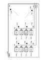
図17は、一実施形態に係る不具合箇所推定システムの適用例を示す図である。本開示に係る不具合箇所推定システム100は、例えば、図17に示すように、複数のチラー1701a~1701hが設置された機械室1700等にも適用することができる。図17の例では、複数のチラー1701a~1701dは、それぞれ、ポンプ1702を介して、水配管1703aに接続されている。同様に、複数のチラー1701a~1701dは、それぞれ、ポンプ1702を介して、水配管1703bに接続されている。 FIG. 17 is a diagram illustrating an application example of the failure location estimation system according to one embodiment. The failure
このように、水配管1703a、1703bが配置された機械室1700では、不具合を検知するセンサとして、漏水センサ1706a、1706bを利用することができる。例えば、図17において、漏水が発生した場合に、漏水が、より低い位置に設けられる排水溝に向かって流れるものとする。 Thus, in the
この場合、推定部611は、漏水センサ1706aのみで漏水が検知されたときに、一例として、チラー1701a~1701d、及びチラー1701a~1701dと水配管1703aとの接続部等を、漏水箇所の候補としても良い。同様に、推定部611は、漏水センサ1706bのみで漏水が検知されたときに、一例として、チラー1701e~1701h、及びチラー1701e~1701hと水配管1703bとの接続部等を、漏水箇所の候補としても良い。また、推定部611は、複数の漏水センサによるセンサ情報と、漏水センサごとの漏水の検知時間とから、不具合が発生した箇所の候補を推定しても良い。 In this case, when the water leakage is detected only by the
また、不具合箇所推定システム100は、複数のチラー1701a~1701hの近くに設けられた音センサ(又は振動センサ)1705a~1705dを用いて、第3の実施形態を適用して、不具合が発生したチラーの候補を推定しても良い。これにより、不具合箇所推定システム100は、複数のチラー1701a~1701hより数が少ない、音センサ(又は振動センサ)1705a~1705dを用いて、不具合が発生したチラーの候補等を示す不具合情報を提供することができる。 In addition, the failure
なお、音センサ(又は振動センサ)1705a~1705dだけでは、例えば、チラーの発熱等の不具合を検知することは困難である。そこで、不具合箇所推定システム100は、例えば、カメラ1704a、1704bを用いて、第4の実施形態を適用して、チラーの発熱等の不具合が発生したチラーの候補等を示す不具合情報を提供しても良い。 It should be noted that it is difficult to detect problems such as heat generation of the chiller only with the sound sensors (or vibration sensors) 1705a to 1705d. Therefore, the failure
このように、不具合箇所推定システム100は、複数の同種類又は異なる種類のセンサのセンサ情報を組み合わせることにより、不具合箇所、又は不具合箇所の候補の推定精度を向上させることができる。 In this manner, the defect
<その他の適用例>
(適用例1)
不具合箇所推定システム100は、2つの温度センサのセンサ情報から、温度差、温度変化の時間差、又は温度差の時間変化等の情報を取得し、取得した情報を用いて、不具合が発生した箇所の方向等を推定しても良い。これにより、不具合箇所推定システム100は、設置位置情報から、不具合が発生した平面、又は不具合が発生した範囲等を限定することができる。<Other application examples>
(Application example 1)
The failure
(適用例2)
不具合箇所推定システム100は、3つ以上の温度センサのセンサ情報から、温度差、温度変化の時間差、又は温度差の時間変化等の情報を取得し、取得した情報を用いて、不具合が発生した箇所の方向等を推定しても良い。これにより、不具合箇所推定システム100は、設置位置情報から、不具合が発生した箇所をさらに限定することができる。例えば、不具合箇所推定システム100は、水平方向だけではなく、垂直方向に設置された配管の接続部等、不具合が発生した範囲を、3次元で限定できるようになる。(Application example 2)
The failure
(適用例3)
不具合箇所推定システム100は、2つのガスセンサのセンサ情報から、ガスの濃度差、濃度変化の時間差、又は濃度差の時間変化等の情報を取得し、取得した情報を用いて、不具合が発生した箇所の方向等を推定しても良い。これにより、不具合箇所推定システム100は、設置位置情報から、不具合が発生した平面、又は不具合が発生した範囲等を限定することができる。(Application example 3)
The failure
(適用例4)
不具合箇所推定システム100は、3つ以上のガスセンサのセンサ情報から、ガスの濃度差、濃度変化の時間差、又は濃度差の時間変化等の情報を取得し、取得した情報を用いて、不具合が発生した箇所の方向等を推定しても良い。これにより、不具合箇所推定システム100は、設置位置情報から、不具合が発生した箇所をさらに限定することができる。例えば、不具合箇所推定システム100は、不具合が発生した範囲を、3次元で限定できるようになる。(Application example 4)
The failure
(適用例5)
不具合箇所推定システム100は、2つの音センサのセンサ情報から、音の強度差を取得し、取得した音の強度差を用いて、不具合が発生した箇所の方向等を推定しても良い。これにより、不具合箇所推定システム100は、設置位置情報から、不具合が発生した平面、又は不具合が発生した範囲等を限定することができる。(Application example 5)
The fault
(適用例6)
不具合箇所推定システム100は、3つ以上の音センサのセンサ情報から、音の強度差を取得し、取得した音の強度差を用いて、不具合が発生した箇所の方向等を推定しても良い。これにより、不具合箇所推定システム100は、設置位置情報から、不具合が発生した箇所をさらに限定することができる。例えば、不具合箇所推定システム100は、不具合が発生した範囲を、3次元で限定できるようになる。(Application example 6)
The defect
(適用例7)
不具合箇所推定システム100は、2つの振動センサのセンサ情報から、振動の強度を取得し、取得した振動の強度を用いて、不具合が発生した箇所の方向等を推定しても良い。これにより、不具合箇所推定システム100は、設置位置情報から、不具合が発生した平面、又は不具合が発生した範囲等を限定することができる。(Application example 7)
The failure
(適用例8)
不具合箇所推定システム100は、3つ以上の振動センサのセンサ情報から、振動の強度を取得し、取得した振動の強度を用いて、不具合が発生した箇所の方向等を推定しても良い。これにより、不具合箇所推定システム100は、設置位置情報から、不具合が発生した箇所をさらに限定することができる。例えば、不具合箇所推定システム100は、不具合が発生した範囲を、3次元で限定できるようになる。(Application example 8)
The failure
(適用例9)
不具合箇所推定システム100は、2つのカメラで撮影した映像と、設置位置情報とを用いて、不具合が発生した箇所等を特定しても良い。例えば、不具合箇所推定システム100は、対象機器の大きさ(画像に示す割合)、又は深度推定技術等により、対象機器までの距離を算出することにより、設置位置情報から不具合が発生した対象機器を特定することができる。(Application example 9)
The fault
(適用例10)
不具合箇所推定システム100は、2つのサーマルカメラ(サーモカメラ)で撮影した映像と、設置位置情報とを用いて、不具合の発生、又は不具合が発生した箇所等を特定しても良い。例えば、不具合箇所推定システム100は、サーマルカメラで撮影した映像から、表面温度、色の変化、又は振動等を検出することにより、不具合が発生したことを特定し、設置位置情報から不具合が発生した箇所等を特定することができる。(Application example 10)
The defect
(適用例11)
不具合箇所推定システム100は、温度センサのセンサ情報とガスセンサのセンサ情報とから、温度の時間変化とガスの濃度変化の情報とを取得し、取得した情報を用いて、漏洩箇所の深刻度(漏れ量等)を推定しても良い。例えば、不具合箇所推定システム100は、温度(熱)の伝搬には時間がかかることから、ガスは検知したが、温度変化がない場合、スローリークと判定しても良い。(Application example 11)
The failure
(適用例12)
不具合箇所推定システム100は、温度センサのセンサ情報と音センサのセンサ情報とから、温度の時間変化と音の強度を取得し、取得した情報を用いて、漏洩箇所の深刻度(漏れ量等)を推定しても良い。例えば、不具合箇所推定システム100は、異音は検知したが、温度変化がない場合、スローリークと判定しても良い。(Application example 12)
The failure
(適用例13)
不具合箇所推定システム100は、ガスセンサのセンサ情報と音センサのセンサ情報とから、不具合が発生した箇所の位置情報、及び漏洩箇所の深刻度(漏れ量等)を推定しても良い。例えば、不具合箇所推定システム100は、ガスの濃度変化と設置位置情報とから不具合箇所の位置情報を推定する。また、不具合箇所推定システム100は、ガスの拡散より音の伝搬の方が早いことから、異音を検出した時刻と、ガス漏れを検出した時刻との時間遅れから、スローリークであるか否かを判定しても良い。(Application example 13)
The fault
(適用例14)
不具合箇所推定システム100は、ガスセンサのセンサ情報と振動センサのセンサ情報とから、不具合が発生した箇所の位置情報、及び漏洩箇所の深刻度(漏れ量等)を推定しても良い。例えば、不具合箇所推定システム100は、ガスの濃度変化と設置位置情報とから不具合箇所の位置情報を推定する。また、不具合箇所推定システム100は、ガスの拡散より振動の伝搬の方が早いことから、振動を検出した時刻と、ガス漏れを検出した時刻との時間遅れから、スローリークであるか否かを判定しても良い。(Application example 14)
The fault
(適用例15)
不具合箇所推定システム100は、2つの温度センサのセンサ情報から、と、適用例1と同様にして不具合が発生した箇所の方向等を推定するとともに、ガスセンサのセンサ情報から、冷媒漏洩であることを確定しても良い。これにより、例えば、温度変化だけでは外的要因(熱源が設置されたなど)による誤検知があるが、ガスセンサを併用して誤検知を防止することができる。(Application example 15)
The failure
(適用例16)
不具合箇所推定システム100は、2つの温度センサのセンサ情報から、と、適用例1と同様にして不具合が発生した箇所の方向等を推定するとともに、音センサのセンサ情報から、不具合が発生した箇所をさらに限定しても良い。例えば、不具合箇所推定システム100は、音センサが取得した音の周波数パターンに応じて、不具合が発生した箇所が機器であるか、配管であるか等を特定しても良い。(Application example 16)
The failure
(適用例17)
不具合箇所推定システム100は、2つの温度センサのセンサ情報から、と、適用例1と同様にして不具合が発生した箇所の方向等を推定するとともに、振動センサのセンサ情報から、不具合が発生した箇所をさらに限定しても良い。例えば、不具合箇所推定システム100は、振動センサのセンサ情報から振動の周波数を取得し、振動の周波数パターンに応じて、不具合が発生した箇所が機器であるか、配管であるか等を特定しても良い。(Application example 17)
The failure
(適用例18)
不具合箇所推定システム100は、2つの温度センサのセンサ情報から、適用例1と同様にして不具合が発生した箇所の方向等を推定するとともに、カメラで撮影した映像を分析することにより、不具合箇所を特定しても良い。これにより、例えば、適用例9のように、カメラで撮影した映像のみから不具合箇所を特定するよりも、不具合を迅速に発見することができる。また、本適用例は、カメラの死角にある不具合箇所の特定にも適用することができる。(Application example 18)
The fault
(適用例19)
不具合箇所推定システム100は、2つのガスセンサのセンサ情報から、適用例3と同様にして、不具合が発生した箇所の方向等を推定するとともに、音センサで取得した音の強度と設置位置情報とから、不具合が発生した箇所をさらに限定しても良い。これにより、不具合箇所推定システム100は、不具合が発生した箇所の推定精度をさらに向上させることができる。(Application example 19)
The fault
(適用例20)
不具合箇所推定システム100は、2つのガスセンサのセンサ情報から、適用例3と同様にして、不具合が発生した箇所の方向等を推定するとともに、振動センサで取得した振動の強度と設置位置情報とから、不具合が発生した箇所をさらに限定しても良い。これにより、不具合箇所推定システム100は、不具合が発生した箇所の推定精度をさらに向上させることができる。(Application example 20)
In the same manner as in Application Example 3, the failure
(適用例21)
不具合箇所推定システム100は、2つのガスセンサのセンサ情報から、適用例3と同様にして、不具合が発生した箇所の方向等を推定するとともに、カメラで撮影した映像を分析することにより、不具合箇所を特定しても良い。これにより、例えば、適用例9のように、カメラで撮影した映像のみから不具合箇所を特定するよりも、不具合を迅速に発見することができる。また、本適用例は、カメラの死角にある不具合箇所の特定にも適用することができる。(Application example 21)
In the same manner as in Application Example 3, the failure
(適用例22)
不具合箇所推定システム100は、2つの音センサのセンサ情報から、適用例5と同様にして、不具合が発生した箇所の方向等を推定するとともに、振動センサで取得した振動の強度と設置位置情報とから、不具合が発生した箇所をさらに限定しても良い。これにより、不具合箇所推定システム100は、不具合が発生した箇所の推定精度をさらに向上させることができる。(Application example 22)
In the same manner as in Application Example 5, the defect
(適用例23)
不具合箇所推定システム100は、2つの音センサのセンサ情報から、適用例5と同様にして、不具合が発生した箇所の方向等を推定するとともに、カメラで撮影した映像を分析することにより、不具合が発生した箇所を特定しても良い。これにより、不具合箇所推定システム100は、例えば、適用例9のように、カメラで撮影した映像のみから不具合箇所を特定するよりも、不具合を迅速に発見することができる。また、本適用例は、カメラの死角にある不具合箇所の特定にも適用することができる。(Application example 23)
In the same manner as in Application Example 5, the failure
(適用例24)
不具合箇所推定システム100は、2つの振動センサのセンサ情報から、適用例7と同様にして、不具合が発生した箇所の方向等を推定するとともに、カメラで撮影した映像を分析することにより、不具合が発生した箇所を特定しても良い。これにより、不具合箇所推定システム100は、例えば、適用例9のように、カメラで撮影した映像のみから不具合箇所を特定するよりも、不具合を迅速に発見することができる。また、本適用例は、カメラの死角にある不具合箇所の特定にも適用することができる。(Application example 24)
In the same manner as in Application Example 7, the defect
以上、実施形態を説明したが、特許請求の範囲の趣旨及び範囲から逸脱することなく、形態や詳細の多様な変更が可能なことが理解されるであろう。 Although the embodiments have been described above, it will be appreciated that various changes in form and detail may be made without departing from the spirit and scope of the claims.
100 不具合箇所推定システム
110 空調システム(冷凍空調システムの一例)
111 空調機器
112 センサ
113 コントローラ(制御部)
120 管理サーバ
203 配管
204a~204h 配管の接続部
211a~211d ダクト
300、400、1000 不具合情報
500 コンピュータ
701、703、704 センサ情報
801 図面情報(設置位置情報の一例)
802 機器座標情報(設置位置情報の一例)
1704a、1704b カメラ
1706a、1706b 漏水センサ100 Defect
111 air conditioner 112
120
802 Device coordinate information (an example of installation position information)
1704a,
Claims (17)
Translated fromJapanese前記制御部は、
前記冷凍空調システムに前記第1のセンサより多く設置され、前記不具合が発生する可能性がある所定の構成要素が設置された位置を示す設置位置情報を有し、
前記第1のセンサと前記第2のセンサとが前記不具合を検知した場合、前記第1のセンサ、及び前記第2のセンサのセンサ情報と、前記設置位置情報とを用いて、前記第1のセンサ、及び前記第2のセンサから所定の距離以内にある前記所定の構成要素を、前記不具合が発生した箇所の候補とし、
前記第1のセンサが前記不具合を検知した第1の時間と、前記第2のセンサが前記不具合を検知した第2の時間との時間差に基づいて、前記所定の距離を変更し、
前記不具合が発生した箇所、前記不具合が発生した箇所の候補、又は前記不具合が発生した範囲を示す不具合情報を出力する、
不具合箇所推定システム。A first sensor that detects a malfunction that has occurred in arefrigeration and air conditioning system, a second sensor that detects a malfunction that has occurred in the refrigeration and air conditioning system, and a control unitthat controls the refrigeration and air conditioning system,
The control unit
Having installation position information indicating a position where a predetermined component that is installed more than the first sensor in the refrigeration and air conditioning system and may cause the malfunction is installed;
When the first sensorand the second sensor detect the malfunction, the first sensor is detected by using the sensor informationof the first sensor and the second sensor and the installation position information. The sensor and the predetermined component within a predetermined distance from the second sensor are candidates for the location where the malfunction has occurred;
changing the predetermined distance based on a time difference between a first time when the first sensor detects the malfunction and a second time when the second sensor detects the malfunction;
outputting defect information indicating a location wherethe defect occurred, a candidate for the location where the defect occurred, or a range where the defect occurred;
Defect location estimation system.
前記制御部は、前記冷凍空調システムに前記第1のセンサより多く設置され、前記不具合が発生する可能性がある所定の構成要素が設置された位置を示す設置位置情報を有し、
前記設置位置情報は、前記冷凍空調システムに含まれる機器と、前記機器に接続される配管又はダクトの接続部との位置を示す情報を含み、
前記第1のセンサは、音を取得する複数の音センサを含み、
前記制御部は、
前記第1のセンサが前記不具合を検知した場合、前記複数の音センサによるセンサ情報と、前記音センサごとの音の大きさ又は検知時間と、前記設置位置情報と、から前記不具合が発生した箇所の候補を推定し、
前記不具合が発生した箇所、前記不具合が発生した箇所の候補、又は前記不具合が発生した範囲を示す不具合情報を出力する、
不具合箇所推定システム。A first sensor that detects a malfunction that has occurred in the refrigeration and air conditioning system, and a control unit that controls the refrigeration and air conditioning system,
The control unit has installation position information indicating a position where a predetermined component that is installed in the refrigeration and air conditioning system more than the first sensor and that may cause the malfunction is installed,
The installation position information includes information indicating the positions of the devices included in the refrigeration and air conditioning system and the connections of pipes or ducts connected to the devices,
the first sensor includes a plurality of sound sensors that acquire sound;
The control unit
When the first sensor detects the defect, the location where the defect occurs based on the sensor information from the plurality of sound sensors, the sound volume or detection time of each of the sound sensors, and the installation position information. estimate candidatesfor
outputting defect information indicating a location where the defect occurred, a candidate for the location where the defect occurred, or a range where the defect occurred;
Defect location estimation system.
前記制御部は、前記冷凍空調システムに前記第1のセンサより多く設置され、前記不具合が発生する可能性がある所定の構成要素が設置された位置を示す設置位置情報を有し、
前記設置位置情報は、前記冷凍空調システムに含まれる機器の位置を示す情報を含み、
前記第1のセンサは、振動を検知する複数の振動センサを含み、
前記制御部は、
前記第1のセンサが前記不具合を検知した場合、前記複数の振動センサによるセンサ情報と、前記振動センサごとの振動の大きさ又は検知時間と、前記設置位置情報と、から前記不具合が発生した箇所の候補を推定し、
前記不具合が発生した箇所、前記不具合が発生した箇所の候補、又は前記不具合が発生した範囲を示す不具合情報を出力する、
不具合箇所推定システム。A first sensor that detects a malfunction that has occurred in the refrigeration and air conditioning system, and a control unit that controls the refrigeration and air conditioning system,
The control unit has installation position information indicating a position where a predetermined component that is installed in the refrigeration and air conditioning system more than the first sensor and that may cause the malfunction is installed,
The installation position information includes information indicating the positions of devices included in the refrigeration and air conditioning system,
The first sensor includes a plurality of vibration sensors that detect vibration,
The control unit
When the first sensor detects the defect, the location where the defect occurs based on the sensor information from the plurality of vibration sensors, the vibration magnitude or detection time of each vibration sensor, and the installation position information. estimate candidatesfor
outputting defect information indicating a location where the defect occurred, a candidate for the location where the defect occurred, or a range where the defect occurred;
Defect location estimation system.
前記制御部は、前記冷凍空調システムに前記第1のセンサより多く設置され、前記不具合が発生する可能性がある所定の構成要素が設置された位置を示す設置位置情報を有し、
前記設置位置情報は、前記冷凍空調システムに含まれる機器に接続される配管の接続部を示す情報を含み、
前記第1のセンサは、漏水を検知する複数の漏水センサを含み、
前記制御部は、
前記第1のセンサが前記不具合を検知した場合、前記複数の漏水センサによるセンサ情報と、前記漏水センサごとの漏水の検知時間とから、前記不具合が発生した箇所の候補を推定し、
前記不具合が発生した箇所、前記不具合が発生した箇所の候補、又は前記不具合が発生した範囲を示す不具合情報を出力する、
不具合箇所推定システム。A first sensor that detects a malfunction that has occurred in the refrigeration and air conditioning system, and a control unit that controls the refrigeration and air conditioning system,
The control unit has installation position information indicating a position where a predetermined component that is installed in the refrigeration and air conditioning system more than the first sensor and that may cause the malfunction is installed,
The installation position information includes information indicating connection portions of pipes connected to equipment included in the refrigeration and air conditioning system,
The first sensor includes a plurality of water leakage sensors that detect water leakage,
The control unit
when the first sensor detects the defect, estimating a candidate for the location where the defect has occurred from thesensor information from the plurality of water leakage sensors and the water leakage detection time for each of the water leakage sensors;
outputting defect information indicating a location where the defect occurred, a candidate for the location where the defect occurred, or a range where the defect occurred;
Defect location estimation system.
前記制御部は、前記冷凍空調システムに前記第1のセンサより多く設置され、前記不具合が発生する可能性がある所定の構成要素が設置された位置を示す設置位置情報を有し、
前記設置位置情報は、前記所定の構成要素の配置を示す図面情報を含み、
前記第1のセンサは、前記所定の構成要素を撮影する1つ以上のカメラを含み、
前記制御部は、
前記第1のセンサが前記不具合を検知した場合、前記1つ以上のカメラが撮影した画像と、前記図面情報とから、前記不具合が発生した箇所の候補を推定し、
前記不具合が発生した箇所、前記不具合が発生した箇所の候補、又は前記不具合が発生した範囲を示す不具合情報を出力する、
不具合箇所推定システム。A first sensor that detects a malfunction that has occurred in the refrigeration and air conditioning system, and a control unit that controls the refrigeration and air conditioning system,
The control unit has installation position information indicating a position where a predetermined component that is installed in the refrigeration and air conditioning system more than the first sensor and that may cause the malfunction is installed,
The installation position information includes drawing information indicating the arrangement of the predetermined components,
The first sensor includes one or more cameras that capture the predetermined component,
The control unit
when the first sensor detects the defect , estimating a candidate for the location where the defect has occurred from the images captured by the one or more cameras and the drawing information;
outputting defect information indicating a location where the defect occurred, a candidate for the location where the defect occurred, or a range where the defect occurred;
Defect location estimation system.
前記制御部が、
前記冷凍空調システムに前記第1のセンサより多く設置され、前記不具合が発生する可能性がある所定の構成要素が設置された位置を示す設置位置情報を有し、
前記第1のセンサと前記第2のセンサとが前記不具合を検知した場合、前記第1のセンサ、及び前記第2のセンサのセンサ情報と、前記設置位置情報とを用いて、前記第1のセンサ、及び前記第2のセンサから所定の距離以内にある前記所定の構成要素を、前記不具合が発生した箇所の候補とし、
前記第1のセンサが前記不具合を検知した第1の時間と、前記第2のセンサが前記不具合を検知した第2の時間との時間差に基づいて、前記所定の距離を変更し、
前記不具合が発生した箇所、前記不具合が発生した箇所の候補、又は前記不具合が発生した範囲を示す不具合情報を出力する、
不具合箇所推定方法。A fault location estimation system comprising: a firstsensor that detects a fault that has occurred in a refrigerating and air-conditioning system; a second sensor that detects a fault that has occurred in the refrigerating and air-conditioning system;and a controller that controls the refrigerating and air-conditioning system. in
The control unit
Having installation position information indicating a position where a predetermined component that is installed more than the first sensor in the refrigeration and air conditioning system and may cause the malfunction is installed;
When the first sensorand the second sensor detect the malfunction, the first sensor is detected by using the sensor informationof the first sensor and the second sensor and the installation position information. The sensor and the predetermined component within a predetermined distance from the second sensor are candidates for the location where the malfunction has occurred;
changing the predetermined distance based on a time difference between a first time when the first sensor detects the malfunction and a second time when the second sensor detects the malfunction;
outputting defect information indicating a location wherethe defect occurred, a candidate for the location where the defect occurred, or a range where the defect occurred;
Defect location estimation method.
前記制御部が、前記冷凍空調システムに前記第1のセンサより多く設置され、前記不具合が発生する可能性がある所定の構成要素が設置された位置を示す設置位置情報を有し、The control unit has installation position information indicating a position where a predetermined component that is installed more than the first sensor in the refrigeration and air conditioning system and may cause the malfunction is installed,
前記設置位置情報は、前記冷凍空調システムに含まれる機器と、前記機器に接続される配管又はダクトの接続部との位置を示す情報を含み、The installation position information includes information indicating the positions of the devices included in the refrigeration and air conditioning system and the connections of pipes or ducts connected to the devices,
前記第1のセンサは、音を取得する複数の音センサを含み、the first sensor includes a plurality of sound sensors that acquire sound;
前記制御部が、The control unit
前記第1のセンサが前記不具合を検知した場合、前記複数の音センサによるセンサ情報と、前記音センサごとの音の大きさ又は検知時間と、前記設置位置情報と、から前記不具合が発生した箇所の候補を推定し、When the first sensor detects the defect, the location where the defect occurs based on the sensor information from the plurality of sound sensors, the sound volume or detection time of each of the sound sensors, and the installation position information. estimate candidates for
前記不具合が発生した箇所、前記不具合が発生した箇所の候補、又は前記不具合が発生した範囲を示す不具合情報を出力する、outputting defect information indicating a location where the defect occurred, a candidate for the location where the defect occurred, or a range where the defect occurred;
不具合箇所推定方法。Defect location estimation method.
前記制御部が、前記冷凍空調システムに前記第1のセンサより多く設置され、前記不具合が発生する可能性がある所定の構成要素が設置された位置を示す設置位置情報を有し、The control unit has installation position information indicating a position where a predetermined component that is installed more than the first sensor in the refrigeration and air conditioning system and may cause the malfunction is installed,
前記設置位置情報は、前記冷凍空調システムに含まれる機器の位置を示す情報を含み、The installation position information includes information indicating the positions of devices included in the refrigeration and air conditioning system,
前記第1のセンサは、振動を検知する複数の振動センサを含み、The first sensor includes a plurality of vibration sensors that detect vibration,
前記制御部が、The control unit
前記第1のセンサが前記不具合を検知した場合、前記複数の振動センサによるセンサ情報と、前記振動センサごとの振動の大きさ又は検知時間と、前記設置位置情報と、から前記不具合が発生した箇所の候補を推定し、 When the first sensor detects the defect, the location where the defect occurs based on the sensor information from the plurality of vibration sensors, the vibration magnitude or detection time of each vibration sensor, and the installation position information. estimate candidates for
前記不具合が発生した箇所、前記不具合が発生した箇所の候補、又は前記不具合が発生した範囲を示す不具合情報を出力する、outputting defect information indicating a location where the defect occurred, a candidate for the location where the defect occurred, or a range where the defect occurred;
不具合箇所推定方法。Defect location estimation method.
前記制御部が、前記冷凍空調システムに前記第1のセンサより多く設置され、前記不具合が発生する可能性がある所定の構成要素が設置された位置を示す設置位置情報を有し、The control unit has installation position information indicating a position where a predetermined component that is installed more than the first sensor in the refrigeration and air conditioning system and may cause the malfunction is installed,
前記設置位置情報は、前記冷凍空調システムに含まれる機器に接続される配管の接続部を示す情報を含み、The installation position information includes information indicating connection portions of pipes connected to equipment included in the refrigeration and air conditioning system,
前記第1のセンサは、漏水を検知する複数の漏水センサを含み、The first sensor includes a plurality of water leakage sensors that detect water leakage,
前記制御部が、The control unit
前記第1のセンサが前記不具合を検知した場合、前記複数の漏水センサによるセンサ情報と、前記漏水センサごとの漏水の検知時間とから、前記不具合が発生した箇所の候補を推定し、 when the first sensor detects the defect, estimating a candidate for the location where the defect has occurred from the sensor information from the plurality of water leakage sensors and the water leakage detection time for each of the water leakage sensors;
前記不具合が発生した箇所、前記不具合が発生した箇所の候補、又は前記不具合が発生した範囲を示す不具合情報を出力する、outputting defect information indicating a location where the defect occurred, a candidate for the location where the defect occurred, or a range where the defect occurred;
不具合箇所推定方法。Defect location estimation method.
前記制御部が、前記冷凍空調システムに前記第1のセンサより多く設置され、前記不具合が発生する可能性がある所定の構成要素が設置された位置を示す設置位置情報を有し、The control unit has installation position information indicating a position where a predetermined component that is installed more than the first sensor in the refrigeration and air conditioning system and may cause the malfunction is installed,
前記設置位置情報は、前記所定の構成要素の配置を示す図面情報を含み、The installation position information includes drawing information indicating the arrangement of the predetermined components,
前記第1のセンサは、前記所定の構成要素を撮影する1つ以上のカメラを含み、The first sensor includes one or more cameras that capture the predetermined component,
前記制御部が、The control unit
前記第1のセンサが前記不具合を検知した場合、前記1つ以上のカメラが撮影した画像と、前記図面情報とから、前記不具合が発生した箇所の候補を推定し、 when the first sensor detects the defect, estimating a candidate for the location where the defect has occurred from the images captured by the one or more cameras and the drawing information;
前記不具合が発生した箇所、前記不具合が発生した箇所の候補、又は前記不具合が発生した範囲を示す不具合情報を出力する、outputting defect information indicating a location where the defect occurred, a candidate for the location where the defect occurred, or a range where the defect occurred;
不具合箇所推定方法。 Defect location estimation method.
前記コンピュータに、
前記冷凍空調システムに前記第1のセンサより多く設置され、前記不具合が発生する可能性がある所定の構成要素が設置された位置を示す設置位置情報を記憶させ、
前記第1のセンサと前記第2のセンサとが前記不具合を検知した場合、前記第1のセンサ、及び前記第2のセンサのセンサ情報と、前記設置位置情報とを用いて、前記第1のセンサ、及び前記第2のセンサから所定の距離以内にある前記所定の構成要素を、前記不具合が発生した箇所の候補とさせ、
前記第1のセンサが前記不具合を検知した第1の時間と、前記第2のセンサが前記不具合を検知した第2の時間との時間差に基づいて、前記所定の距離を変更させ、
前記不具合が発生した箇所、前記不具合が発生した箇所の候補、又は前記不具合が発生した範囲を示す不具合情報を出力させる、
プログラム。A fault location estimation system comprising: a firstsensor that detects a fault that has occurred in a refrigerating and air-conditioning system; a second sensor that detects a fault that has occurred in the refrigerating and air-conditioning system;and a computer that controls the refrigerating and air-conditioning system ,
to the computer;
storing installation position information indicating a position where a predetermined component that is installed in the refrigeration and air conditioning system more than the first sensor and that may cause the malfunction is installed;
When the first sensorand the second sensor detect the malfunction, the first sensor is detected by using the sensor informationof the first sensor and the second sensor and the installation position information. The sensor and the predetermined component within a predetermined distance from the second sensor are candidates for the location where the malfunction has occurred;
changing the predetermined distance based on a time difference between a first time when the first sensor detects the malfunction and a second time when the second sensor detects the malfunction;
outputting defect information indicating a location wherethe defect occurred, a candidate for the location where the defect occurred, or a range where the defect occurred;
program.
前記コンピュータに、前記冷凍空調システムに前記第1のセンサより多く設置され、前記不具合が発生する可能性がある所定の構成要素が設置された位置を示す設置位置情報を記憶させ、causing the computer to store installation position information indicating a position where a predetermined component that is installed in the refrigeration and air conditioning system more than the first sensor and that may cause the malfunction is installed;
前記設置位置情報は、前記冷凍空調システムに含まれる機器と、前記機器に接続される配管又はダクトの接続部との位置を示す情報を含み、The installation position information includes information indicating the positions of the devices included in the refrigeration and air conditioning system and the connections of pipes or ducts connected to the devices,
前記第1のセンサは、音を取得する複数の音センサを含み、the first sensor includes a plurality of sound sensors that acquire sound;
前記コンピュータに、to the computer;
前記第1のセンサが前記不具合を検知した場合、前記複数の音センサによるセンサ情報と、前記音センサごとの音の大きさ又は検知時間と、前記設置位置情報と、から前記不具合が発生した箇所の候補を推定させ、When the first sensor detects the defect, the location where the defect occurs based on the sensor information from the plurality of sound sensors, the sound volume or detection time of each of the sound sensors, and the installation position information. to estimate candidates for
前記不具合が発生した箇所、前記不具合が発生した箇所の候補、又は前記不具合が発生した範囲を示す不具合情報を出力させる、outputting defect information indicating a location where the defect occurred, a candidate for the location where the defect occurred, or a range where the defect occurred;
プログラム。program.
前記コンピュータに、前記冷凍空調システムに前記第1のセンサより多く設置され、前記不具合が発生する可能性がある所定の構成要素が設置された位置を示す設置位置情報を記憶させ、causing the computer to store installation position information indicating a position where a predetermined component that is installed in the refrigeration and air conditioning system more than the first sensor and that may cause the malfunction is installed;
前記設置位置情報は、前記冷凍空調システムに含まれる機器の位置を示す情報を含み、The installation position information includes information indicating the positions of devices included in the refrigeration and air conditioning system,
前記第1のセンサは、振動を検知する複数の振動センサを含み、The first sensor includes a plurality of vibration sensors that detect vibration,
前記コンピュータに、to the computer;
前記第1のセンサが前記不具合を検知した場合、前記複数の振動センサによるセンサ情報と、前記振動センサごとの振動の大きさ又は検知時間と、前記設置位置情報と、から前記不具合が発生した箇所の候補を推定させ、 When the first sensor detects the defect, the location where the defect occurs based on the sensor information from the plurality of vibration sensors, the vibration magnitude or detection time of each vibration sensor, and the installation position information. to estimate candidates for
前記不具合が発生した箇所、前記不具合が発生した箇所の候補、又は前記不具合が発生した範囲を示す不具合情報を出力させる、outputting defect information indicating a location where the defect occurred, a candidate for the location where the defect occurred, or a range where the defect occurred;
プログラム。program.
前記コンピュータに、前記冷凍空調システムに前記第1のセンサより多く設置され、前記不具合が発生する可能性がある所定の構成要素が設置された位置を示す設置位置情報を記憶させ、causing the computer to store installation position information indicating a position where a predetermined component that is installed in the refrigeration and air conditioning system more than the first sensor and that may cause the malfunction is installed;
前記設置位置情報は、前記冷凍空調システムに含まれる機器に接続される配管の接続部を示す情報を含み、The installation position information includes information indicating connection portions of pipes connected to equipment included in the refrigeration and air conditioning system,
前記第1のセンサは、漏水を検知する複数の漏水センサを含み、The first sensor includes a plurality of water leakage sensors that detect water leakage,
前記コンピュータに、to the computer;
前記第1のセンサが前記不具合を検知した場合、前記複数の漏水センサによるセンサ情報と、前記漏水センサごとの漏水の検知時間とから、前記不具合が発生した箇所の候補を推定させ、 when the first sensor detects the defect, estimating a candidate for the location where the defect has occurred based on sensor information from the plurality of water leakage sensors and a water leakage detection time for each of the water leakage sensors;
前記不具合が発生した箇所、前記不具合が発生した箇所の候補、又は前記不具合が発生した範囲を示す不具合情報を出力させる、outputting defect information indicating a location where the defect occurred, a candidate for the location where the defect occurred, or a range where the defect occurred;
プログラム。program.
前記コンピュータに、前記冷凍空調システムに前記第1のセンサより多く設置され、前記不具合が発生する可能性がある所定の構成要素が設置された位置を示す設置位置情報を記憶させ、causing the computer to store installation position information indicating a position where a predetermined component that is installed in the refrigeration and air conditioning system more than the first sensor and that may cause the malfunction is installed;
前記設置位置情報は、前記所定の構成要素の配置を示す図面情報を含み、The installation position information includes drawing information indicating the arrangement of the predetermined components,
前記第1のセンサは、前記所定の構成要素を撮影する1つ以上のカメラを含み、The first sensor includes one or more cameras that capture the predetermined component,
前記コンピュータに、to the computer;
前記第1のセンサが前記不具合を検知した場合、前記1つ以上のカメラが撮影した画像と、前記図面情報とから、前記不具合が発生した箇所の候補を推定させ、 when the first sensor detects the defect, estimating a candidate for the location where the defect has occurred from the images captured by the one or more cameras and the drawing information;
前記不具合が発生した箇所、前記不具合が発生した箇所の候補、又は前記不具合が発生した範囲を示す不具合情報を出力させる、outputting defect information indicating a location where the defect occurred, a candidate for the location where the defect occurred, or a range where the defect occurred;
プログラム。program.
Priority Applications (1)
| Application Number | Priority Date | Filing Date | Title |
|---|---|---|---|
| JP2022193061AJP7545069B2 (en) | 2021-01-08 | 2022-12-01 | Fault location estimation system, fault location estimation method, and program |
Applications Claiming Priority (2)
| Application Number | Priority Date | Filing Date | Title |
|---|---|---|---|
| JP2021001922 | 2021-01-08 | ||
| JP2021001922 | 2021-01-08 |
Related Child Applications (1)
| Application Number | Title | Priority Date | Filing Date |
|---|---|---|---|
| JP2022193061ADivisionJP7545069B2 (en) | 2021-01-08 | 2022-12-01 | Fault location estimation system, fault location estimation method, and program |
Publications (2)
| Publication Number | Publication Date |
|---|---|
| JP2022107519A JP2022107519A (en) | 2022-07-21 |
| JP7189468B2true JP7189468B2 (en) | 2022-12-14 |
Family
ID=82357992
Family Applications (2)
| Application Number | Title | Priority Date | Filing Date |
|---|---|---|---|
| JP2021214167AActiveJP7189468B2 (en) | 2021-01-08 | 2021-12-28 | Defect point estimation system, defect point estimation method, and program |
| JP2022193061AActiveJP7545069B2 (en) | 2021-01-08 | 2022-12-01 | Fault location estimation system, fault location estimation method, and program |
Family Applications After (1)
| Application Number | Title | Priority Date | Filing Date |
|---|---|---|---|
| JP2022193061AActiveJP7545069B2 (en) | 2021-01-08 | 2022-12-01 | Fault location estimation system, fault location estimation method, and program |
Country Status (6)
| Country | Link |
|---|---|
| US (1) | US20240053220A1 (en) |
| EP (1) | EP4276375A4 (en) |
| JP (2) | JP7189468B2 (en) |
| CN (1) | CN116783430A (en) |
| AU (1) | AU2022206133B2 (en) |
| WO (1) | WO2022149597A1 (en) |
Families Citing this family (6)
| Publication number | Priority date | Publication date | Assignee | Title |
|---|---|---|---|---|
| US10119738B2 (en) | 2014-09-26 | 2018-11-06 | Waterfurnace International Inc. | Air conditioning system with vapor injection compressor |
| US10871314B2 (en) | 2016-07-08 | 2020-12-22 | Climate Master, Inc. | Heat pump and water heater |
| US10866002B2 (en) | 2016-11-09 | 2020-12-15 | Climate Master, Inc. | Hybrid heat pump with improved dehumidification |
| US11592215B2 (en) | 2018-08-29 | 2023-02-28 | Waterfurnace International, Inc. | Integrated demand water heating using a capacity modulated heat pump with desuperheater |
| CA3081986A1 (en) | 2019-07-15 | 2021-01-15 | Climate Master, Inc. | Air conditioning system with capacity control and controlled hot water generation |
| US12181189B2 (en) | 2021-11-10 | 2024-12-31 | Climate Master, Inc. | Ceiling-mountable heat pump system |
Citations (7)
| Publication number | Priority date | Publication date | Assignee | Title |
|---|---|---|---|---|
| JP2004127047A (en) | 2002-10-04 | 2004-04-22 | Daikin Ind Ltd | Monitoring device, monitoring program, and monitoring method for environmental adjustment equipment |
| JP2010134367A (en) | 2008-12-08 | 2010-06-17 | Mitsubishi Electric Corp | Electric equipment |
| JP2012172912A (en) | 2011-02-22 | 2012-09-10 | Mitsubishi Electric Corp | Management device, management system, management method, and program |
| JP2013234797A (en) | 2012-05-09 | 2013-11-21 | Hitachi Appliances Inc | Air conditioner |
| JP2018009772A (en) | 2016-07-15 | 2018-01-18 | 日立ジョンソンコントロールズ空調株式会社 | Cooling/heating switching unit and air conditioner including the same |
| WO2018216127A1 (en) | 2017-05-24 | 2018-11-29 | 三菱電機株式会社 | Air conditioning system |
| JP2020197347A (en) | 2019-06-03 | 2020-12-10 | ダイキン工業株式会社 | Apparatus management device and heat source system |
Family Cites Families (19)
| Publication number | Priority date | Publication date | Assignee | Title |
|---|---|---|---|---|
| JPH06198586A (en)* | 1993-01-07 | 1994-07-19 | Toshiba Corp | Moving robot |
| CN102056784A (en)* | 2008-06-11 | 2011-05-11 | 三菱电机株式会社 | Vehicle air conditioner, vehicle air conditioner management system, and vehicle air conditioner management method |
| JP2017525732A (en) | 2014-08-25 | 2017-09-07 | エイチエルアイ セルラー セラピューティックス,リミテッド ライアビリティー カンパニーHli Cellular Therapeutics,Llc | Extracellular matrix composition |
| JP6532605B2 (en)* | 2016-05-18 | 2019-06-19 | 三菱電機株式会社 | Air conditioner |
| CN110199162B (en)* | 2017-01-19 | 2021-09-14 | 三菱电机株式会社 | Refrigeration cycle device |
| CN110291338B (en)* | 2017-01-20 | 2022-01-18 | 三菱电机株式会社 | Air conditioning apparatus |
| EP3591304B1 (en)* | 2017-03-02 | 2023-04-05 | Mitsubishi Electric Corporation | Refrigeration cycle device and refrigeration cycle system |
| JP6418346B2 (en)* | 2017-03-31 | 2018-11-07 | ダイキン工業株式会社 | Method for detecting refrigerant leak location |
| US11280513B2 (en)* | 2017-07-31 | 2022-03-22 | Ilmastointimittaus Lind Oy | Arrangement and method for determination of adjustment parameters of an HVAC system |
| ES2953351T3 (en)* | 2017-08-03 | 2023-11-10 | Daikin Ind Ltd | Cooling device |
| DE112017007962T5 (en)* | 2017-08-21 | 2020-07-09 | Mitsubishi Electric Corporation | Air conditioning and expansion valve unit |
| US11573149B2 (en)* | 2017-12-01 | 2023-02-07 | Johnson Controls Tyco IP Holdings LLP | Systems and methods for refrigerant leak management based on acoustic leak detection |
| EP3584522B1 (en)* | 2018-05-10 | 2021-04-14 | Mitsubishi Electric Corporation | Refrigerant leak determination device, air conditioner, and refrigerant leak determination method |
| CN109028456B (en)* | 2018-08-30 | 2021-04-30 | 海信(山东)空调有限公司 | Refrigerant leakage detection method and device |
| JP6815377B2 (en)* | 2018-12-26 | 2021-01-20 | 日立ジョンソンコントロールズ空調株式会社 | Air conditioner unit and air conditioner |
| US11579601B2 (en)* | 2019-01-15 | 2023-02-14 | Pricemy Developer LLC | Methods and devices for a building monitoring system |
| JP7268493B2 (en) | 2019-06-20 | 2023-05-08 | 株式会社リコー | Imaging device and imaging method |
| CN110779126A (en)* | 2019-10-31 | 2020-02-11 | 长兴吉数科技有限公司 | Automatic water leakage isolation system for IDC machine room air conditioning system |
| CN110986320A (en)* | 2019-12-13 | 2020-04-10 | 海尔(深圳)研发有限责任公司 | Method and device for air conditioner abnormity control, air conditioner and server |
- 2021
- 2021-12-28JPJP2021214167Apatent/JP7189468B2/enactiveActive
- 2022
- 2022-01-06USUS18/260,277patent/US20240053220A1/enactivePending
- 2022-01-06EPEP22736765.3Apatent/EP4276375A4/enactivePending
- 2022-01-06CNCN202280009261.2Apatent/CN116783430A/enactivePending
- 2022-01-06AUAU2022206133Apatent/AU2022206133B2/enactiveActive
- 2022-01-06WOPCT/JP2022/000232patent/WO2022149597A1/ennot_activeCeased
- 2022-12-01JPJP2022193061Apatent/JP7545069B2/enactiveActive
Patent Citations (7)
| Publication number | Priority date | Publication date | Assignee | Title |
|---|---|---|---|---|
| JP2004127047A (en) | 2002-10-04 | 2004-04-22 | Daikin Ind Ltd | Monitoring device, monitoring program, and monitoring method for environmental adjustment equipment |
| JP2010134367A (en) | 2008-12-08 | 2010-06-17 | Mitsubishi Electric Corp | Electric equipment |
| JP2012172912A (en) | 2011-02-22 | 2012-09-10 | Mitsubishi Electric Corp | Management device, management system, management method, and program |
| JP2013234797A (en) | 2012-05-09 | 2013-11-21 | Hitachi Appliances Inc | Air conditioner |
| JP2018009772A (en) | 2016-07-15 | 2018-01-18 | 日立ジョンソンコントロールズ空調株式会社 | Cooling/heating switching unit and air conditioner including the same |
| WO2018216127A1 (en) | 2017-05-24 | 2018-11-29 | 三菱電機株式会社 | Air conditioning system |
| JP2020197347A (en) | 2019-06-03 | 2020-12-10 | ダイキン工業株式会社 | Apparatus management device and heat source system |
Also Published As
| Publication number | Publication date |
|---|---|
| EP4276375A1 (en) | 2023-11-15 |
| WO2022149597A1 (en) | 2022-07-14 |
| JP2022107519A (en) | 2022-07-21 |
| JP7545069B2 (en) | 2024-09-04 |
| CN116783430A (en) | 2023-09-19 |
| AU2022206133B2 (en) | 2024-10-24 |
| EP4276375A4 (en) | 2024-06-19 |
| JP2023025165A (en) | 2023-02-21 |
| US20240053220A1 (en) | 2024-02-15 |
| AU2022206133A1 (en) | 2023-07-27 |
Similar Documents
| Publication | Publication Date | Title |
|---|---|---|
| JP7189468B2 (en) | Defect point estimation system, defect point estimation method, and program | |
| JP6734940B2 (en) | Three-dimensional measuring device | |
| US20190355177A1 (en) | Building system maintenance using mixed reality | |
| US20130182103A1 (en) | Automatic Configuration of Cameras in Building Information Modeling | |
| Vidas et al. | Real-time mobile 3D temperature mapping | |
| CN104574267A (en) | Guiding method and information processing apparatus | |
| JP7129403B2 (en) | Air conditioner selection system | |
| KR20180101746A (en) | Method, electronic device and system for providing augmented reality contents | |
| US11616699B2 (en) | Obtaining location metadata for network devices using augmented reality | |
| JP6854631B2 (en) | Information visualization system, information visualization method, and program | |
| US10565786B1 (en) | Sensor placement interface | |
| JP6688518B1 (en) | Method for determining coordinate axis and surface identification method in three-dimensional space | |
| CN111465906B (en) | Automatic allocation between flow control devices, sensor devices and control devices in HVAC applications | |
| JP4967699B2 (en) | Gap verification device, CAD system, and computer program | |
| CN112015267A (en) | System, apparatus and method for managing a building automation environment | |
| US11838346B2 (en) | Apparatus for light weighted setting spatial data of 3D modeling data and video monitoring | |
| JP6548683B2 (en) | Object image estimation device and object image determination device | |
| CA3067391C (en) | Interfaces for resolving maintenance activities | |
| JP2011154449A (en) | Congestion level measuring device | |
| KR102757694B1 (en) | Method, device and system for platform service to manage quality and performance rate of cleaning service based on user shooting and sensor data | |
| JP2013033386A (en) | House information providing system, house information providing method, and house information providing program | |
| JP7713677B2 (en) | Estimation method, program, and estimation system | |
| WO2025211187A1 (en) | Estimation device, system, method for controlling estimation device, and storage medium | |
| JP2010182138A (en) | System design support apparatus | |
| JP2023150338A (en) | Data processing device and program |
Legal Events
| Date | Code | Title | Description |
|---|---|---|---|
| A621 | Written request for application examination | Free format text:JAPANESE INTERMEDIATE CODE: A621 Effective date:20211228 | |
| A131 | Notification of reasons for refusal | Free format text:JAPANESE INTERMEDIATE CODE: A131 Effective date:20220201 | |
| A521 | Request for written amendment filed | Free format text:JAPANESE INTERMEDIATE CODE: A523 Effective date:20220404 | |
| A131 | Notification of reasons for refusal | Free format text:JAPANESE INTERMEDIATE CODE: A131 Effective date:20220816 | |
| A521 | Request for written amendment filed | Free format text:JAPANESE INTERMEDIATE CODE: A523 Effective date:20221017 | |
| TRDD | Decision of grant or rejection written | ||
| A01 | Written decision to grant a patent or to grant a registration (utility model) | Free format text:JAPANESE INTERMEDIATE CODE: A01 Effective date:20221101 | |
| A61 | First payment of annual fees (during grant procedure) | Free format text:JAPANESE INTERMEDIATE CODE: A61 Effective date:20221114 | |
| R151 | Written notification of patent or utility model registration | Ref document number:7189468 Country of ref document:JP Free format text:JAPANESE INTERMEDIATE CODE: R151 |