JP7189046B2 - Tactile sensation presentation device and tactile sensation presentation apparatus - Google Patents
Tactile sensation presentation device and tactile sensation presentation apparatusDownload PDFInfo
- Publication number
- JP7189046B2 JP7189046B2JP2019029801AJP2019029801AJP7189046B2JP 7189046 B2JP7189046 B2JP 7189046B2JP 2019029801 AJP2019029801 AJP 2019029801AJP 2019029801 AJP2019029801 AJP 2019029801AJP 7189046 B2JP7189046 B2JP 7189046B2
- Authority
- JP
- Japan
- Prior art keywords
- tactile sensation
- presentation device
- panel
- fingertip
- touch panel
- Prior art date
- Legal status (The legal status is an assumption and is not a legal conclusion. Google has not performed a legal analysis and makes no representation as to the accuracy of the status listed.)
- Active
Links
Images


Landscapes
- Input From Keyboards Or The Like (AREA)
- User Interface Of Digital Computer (AREA)
Description
Translated fromJapanese本発明は、触感提示デバイス及び触感提示装置に関する。 The present invention relates to a tactile sensation presentation device and a tactile sensation presentation apparatus.
近年、スマートフォン、スマートウォッチ、タブレット型PC等の携帯情報端末や、車載用ナビゲーション装置等の電子機器等には、操作者の操作に対して、振動によって触感を提示する装置が組み込まれている場合が多い。この種の装置の振動源としては、例えば電磁ソレノイド、電磁型リニアアクチュエータ、回転型の振動モータ、或いは形状記憶合金ワイヤを利用したアクチュエータ等が採用されていることが知られている。 In recent years, mobile information terminals such as smartphones, smart watches, tablet PCs, and electronic devices such as in-vehicle navigation devices have incorporated devices that present tactile sensations by vibration in response to operator operations. There are many. It is known that an electromagnetic solenoid, an electromagnetic linear actuator, a rotary vibration motor, an actuator using a shape memory alloy wire, or the like is employed as a vibration source for this type of device.
例えば下記特許文献1に示されるように、タッチパネルの前面側に配置された接触パネルを指先で触った際に、形状記憶合金ワイヤを利用して接触パネルを瞬間的に移動させて、指先に対して力学的な操作感覚(いわゆるクリック感のような触覚)を疑似的に作用させる触感提示装置が知られている。 For example, as shown in
さらには下記特許文献2に示されるように、タッチパネルを支持するケーシングに固定された固定部材と、タッチパネルに連結されると共に固定部材に対して弾性部材を介して支持される可動部材と、を備え、可動部材の振動をタッチパネルに伝達する触覚型ソレノイドを具備する装置が知られている。 Furthermore, as shown in
一般的に、指先をタッチするタッチパネル(接触パネルも同様)は、合成樹脂製或いはガラス製の板状部材とされ、その表面は平坦に形成されている。そのため、上記従来の装置等によってタッチパネルを振動させたとしても、タッチパネルに触れた指先に対して力学的な操作感覚である触感を効果的に与えることが難しい。従って、強い触感を指先に与えることが難しく、改善の余地があった。さらに毎回決まった触感のパターンになり易いので、やはり改善の余地があった。 Generally, a touch panel (the same applies to a touch panel) that is touched by a fingertip is a plate-shaped member made of synthetic resin or glass, and the surface thereof is formed flat. Therefore, even if the touch panel is vibrated by the above-described conventional device, it is difficult to effectively give a tactile sensation, which is a mechanical operation sensation, to the fingertip that touches the touch panel. Therefore, it is difficult to give a strong tactile sensation to the fingertips, and there is room for improvement. Furthermore, since the tactile sensation pattern tends to be fixed each time, there is still room for improvement.
本発明は、このような事情に考慮してなされたもので、その目的は、操作者の操作に対して多様な触感を効果的に与えることができる触感提示デバイス及び触感提示装置を提供することである。 SUMMARY OF THE INVENTION The present invention has been made in consideration of such circumstances, and an object thereof is to provide a tactile sensation presentation device and a tactile sensation presentation apparatus capable of effectively imparting various tactile sensations to an operator's operation. is.
(1)本発明に係る触感提示デバイスは、指先で操作される操作面を有し、少なくとも指先による操作時に瞬間的に振動する操作パネルと、前記操作パネルを通じて、少なくとも情報を表示する表示パネルと、を備え、前記操作面の少なくとも一部には、前記操作面における他の部分の表面粗さよりも粗面化された粗面部が設けられ、前記表示パネルは、複数の仮想ボタンを表示可能とされ、前記操作面は、複数の前記仮想ボタンのうち特定の仮想ボタンを操作するための特定ボタン領域を有し、前記粗面部は、前記特定ボタン領域に設けられ、前記粗面部は、前記操作面から突出した凸部、又は前記操作面から窪んだ凹部のいずれか一方を備え、前記凸部又は前記凹部は、前記操作パネルの厚さ方向から見た平面視で、前記特定の仮想ボタンの周囲を囲むように、連続的に繋がった枠状に形成されていることを特徴とする。(1) A tactile sensation presentation device according to the present invention includes an operation panel that has an operation surface that is operated with a fingertip, that vibrates momentarily at least when operated by a fingertip, and a display panel that displays at least information through the operation panel. , wherein at least a part of the operation surface is provided with a roughened surface portion that is rougher than other portions of the operation surface, and the display panel is capable of displaying a plurality of virtual buttons. The operation surface has a specific button area for operating a specific virtual button among the plurality of virtual buttons, the rough surface portion is provided in the specific button area, and the rough surface portion is provided for the operation Either a convex portion protruding from the surface or a concave portion recessed from the operation surface is provided, and the convex portion or the concave portion corresponds to the specific virtual button when viewed from above in the thickness direction of the operation panel. It is characterizedby being formed in a continuously connected frame shape so as to surround the periphery .
本発明に係る触感提示デバイスによれば、表示パネルに表示された情報を視認しながら、操作パネルを指先で操作する際に、操作パネルが瞬間的に振動する。そのため、操作パネルに触れた指先に対して、力学的な操作感覚を疑似的に作用させることができ、指先に対してクリック感を与えるような触感を与えることができる。
特に、操作面の少なくとも一部に粗面部が設けられているので、粗面部を指先で触れながら操作パネルを操作することができる。このとき、粗面部に触れた指先に対して物理的な刺激(触感)を与えることができるので、粗面部を触れないで操作パネルを操作した場合に比べて、操作パネルの振動に伴って指先に対して大きな触感を与えることができる。これにより、従来では感じ得ない、大きく且つ独特な触感を指先に与えることができる。また、例えば粗面部の形状等を工夫することで、多様な触感を与えることが可能となるので、触感のバリエーションを容易に増やすことができる。According to the tactile sensation presentation device of the present invention, the operation panel vibrates momentarily when the operation panel is operated with a fingertip while viewing information displayed on the display panel. Therefore, it is possible to give a pseudo mechanical operation feeling to the fingertip that touches the operation panel, and it is possible to give a tactile sensation such as a click feeling to the fingertip.
In particular, since at least a part of the operation surface is provided with a rough surface portion, the operation panel can be operated while touching the rough surface portion with a fingertip. At this time, since a physical stimulation (tactile sensation) can be given to the fingertip that touches the rough surface portion, the fingertip is more sensitive to the vibration of the operation panel than when the operation panel is operated without touching the rough surface portion. can give a great feeling to As a result, it is possible to give the fingertips a large and unique tactile sensation that cannot be felt conventionally. In addition, for example, by devising the shape of the rough surface portion, etc., it is possible to give various tactile sensations, so that it is possible to easily increase the variation of tactile sensations.
さらに、特定ボタン領域に粗面部が設けられているので、操作パネルを指先で触れて特定の仮想ボタンを入力操作するときに、粗面部を利用して指先に対して大きな触感を効果的に与えることができる。従って、特定の仮想ボタンの入力操作と、他の仮想ボタンの入力操作とで、指先に与える触感を異ならせることができる。従って、特定の仮想ボタンを、例えば緊急性の高い仮想ボタン或いは重要度の高い仮想ボタンとして利用することで、これらの仮想ボタンを入力操作するときに、より刺激の強い触感を与えるといった使い方を行える。Further , since the specific button area is provided with the rough surface, when the operation panel is touched with the fingertip to perform the input operation of the specific virtual button, the rough surface effectively gives the fingertip a large tactile sensation. be able to. Therefore, the tactile sensation given to the fingertip can be made different between the input operation of a specific virtual button and the input operation of another virtual button. Therefore, by using a specific virtual button, for example, as a virtual button with high urgency or a virtual button with high importance, it is possible to use these virtual buttons to provide a more stimulating tactile sensation when performing an input operation. .
さらに、操作パネルを指先で触れて特定の仮想ボタンを入力操作する際に、凸部の出っ張り感又は凹部の凹み感を指先に対して与えることができるので、指先に対してより大きな触感を与え易い。さらに凸部又は凹部を設けるだけで粗面部を構成できるので、構成の簡略化を図ることができる。さらに凸部又は凹部の形状等を工夫することで、指先に対して異なった触感を与えることが可能であるので、多様なバリエーションの触感を容易に与えることが可能となる。Furthermore , when a user touches the operation panel with a fingertip to perform an input operation on a specific virtual button, the fingertip can be given a bulging feeling of a convex portion or a concave feeling of a concave portion. easy. Further, since the rough surface portion can be configured by simply providing the convex portion or the concave portion, the configuration can be simplified. Furthermore, by devising the shape of the projections or recesses, it is possible to give different tactile sensations to the fingertips, so that it is possible to easily give various variations of tactile sensations.
さらに、凸部又は凹部が特定の仮想ボタンの周囲を囲むように枠状に形成されているので、操作パネルを指先で触れて特定の仮想ボタンを入力操作する際に、指先を凸部又は凹部に触れ易くすることができる。Further , since the projections or recesses are formed in a frame shape so as to surround the specific virtual button, when touching the operation panel with a finger to perform an input operation on the specific virtual button, the fingertip can be placed on the projection or recess. can be easily accessed.
(2)前記凸部は、前記操作パネルとは別体に形成され、前記操作面上に組み合わされても良い。(2 ) The convex portion may be formed separately from the operation panel and combined with the operation surface.
この場合には、操作パネルの操作面上に例えば凸部を接着、貼着等によって組み合わせるだけで粗面部を構成できるので、構成の簡略化を図ることができると共に低コスト化を図り易い。さらに、必要に応じて凸部の付替え等を行うことも可能であるので、例えば凸部の位置修正や形状の異なる別の凸部への交換等を行うことができ、使い易さを向上することができる。 In this case, the rough surface portion can be formed simply by combining, for example, the convex portion on the operation surface of the operation panel by gluing, sticking, or the like, so that the structure can be simplified and the cost can be easily reduced. Furthermore, since it is also possible to change the position of the convex portion as necessary, for example, it is possible to correct the position of the convex portion or replace it with another convex portion having a different shape, thereby improving ease of use. can do.
(3)前記操作パネルは、前記操作面の面内方向に振動しても良い。(3 ) The operation panel may vibrate in an in-plane direction of the operation surface.
この場合には、操作パネルに触れた指先の腹の部分に対して、滑らすように操作パネルを振動させることができるので、指先に対してより効果的な触感を与えることができる。特に、凸部又は凹部で粗面部を構成している場合には、凸部の突出方向又は凹部の凹み方向に対して直交するように操作パネルを振動させることができるので、指先に対してさらに効果的な触感を与えることができる。 In this case, since the operation panel can be vibrated so as to slide the pad of the fingertip touching the operation panel, the fingertip can be provided with a more effective tactile sensation. In particular, when the rough surface portion is composed of projections or recesses, the operation panel can be vibrated so as to be perpendicular to the projection direction of the projections or the recession direction of the recesses. It can give an effective tactile sensation.
(4)前記粗面部は、複数設けられ、互いに表面粗さが異なっても良い。(4 ) A plurality of rough surface portions may be provided, each having a different surface roughness.
この場合には、例えば特定の仮想ボタンの内容、種類等によって、指先に与える触感を容易に異ならせることができる。 In this case, it is possible to easily vary the tactile sensation given to the fingertip, for example, depending on the content, type, etc. of the specific virtual button.
(5)本発明に係る触感提示装置は、前記触感提示デバイスと、前記触感提示デバイスに組み合わされるケーシングと、前記ケーシング内に収容され、前記操作パネルに対して振動を与えるアクチュエータと、前記ケーシング内に収容され、前記操作パネルの操作に応じて前記表示パネルの表示を制御する制御部と、を備えることを特徴とする。(5 ) A tactile sensation presentation device according to the present invention includes: the tactile sensation presentation device; a casing combined with the tactile sensation presentation device; an actuator housed in the casing to apply vibration to the operation panel; and a control unit that is housed in the control panel and controls the display of the display panel according to the operation of the operation panel.
本発明に係る触感提示装置によれば、触感提示デバイスにより、従来では感じ得ない、大きく且つ独特で多様な触感を指先に与えることができるので、スマートフォンやスマートウォッチ等の携帯情報端末等として好適に利用することができる。特に、大きな触感を指先に与えることができるので、例えば振動を受け易い状況下であっても、指先に対して明確な触感を与えることができる。従って、例えば車載用途、或いは操作者に装着或いは操作者が所持した状態で使用するようなウエラブル用途等に、好適に利用することができる。 According to the tactile sensation presentation device according to the present invention, the tactile sensation presentation device can give the fingertips large, unique and diverse tactile sensations that cannot be felt in the past, so it is suitable for personal digital assistants such as smartphones and smart watches. can be used for In particular, since a strong tactile sensation can be imparted to the fingertips, a clear tactile sensation can be imparted to the fingertips even under conditions where vibrations are likely to occur. Therefore, it can be suitably used for, for example, vehicle-mounted applications, or wearable applications such as being worn by an operator or used while being held by an operator.
本発明によれば、操作者の操作に対して多様な触感を効果的に与えることができる。 ADVANTAGE OF THE INVENTION According to this invention, various tactile sensations can be effectively given with respect to an operator's operation.
以下、本発明に係る一実施形態について図面を参照して説明する。本実施形態では、触感提示装置として、車載用のカーナビゲーション装置を例に挙げて説明する。 An embodiment according to the present invention will be described below with reference to the drawings. In the present embodiment, an in-vehicle car navigation device will be described as an example of a tactile presentation device.
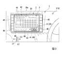
図1に示すように、本実施形態のカーナビゲーション装置1は、車両VにおけるインストルメントパネルPに取り付けられている。具体的には、カーナビゲーション装置1は、インストルメントパネルPのうち運転席と助手席との間に一体的に組み込まれるように取り付けられている。ただし、カーナビゲーション装置1の位置及び固定方法等は、この場合に限定されるものではなく、適宜変更して構わない。 As shown in FIG. 1, a
図1及び図2に示すように、カーナビゲーション装置1は、ケーシング2と、ケーシング2に対して組み合わされた触感提示デバイス3と、ケーシング2内に収容され、後述するタッチパネル20に対して振動を与えるアクチュエータ4と、ケーシング2内に収容され、タッチパネル20の操作に応じて後述する表示パネル21の表示を制御する制御部5と、を備えている。 As shown in FIGS. 1 and 2, the
本実施形態では、ケーシング2の平面視でケーシング2の厚さ方向L1に対して互いに直交する2方向を第1方向L2及び第2方向L3という。よって、第1方向L2及び第2方向L3は、ケーシング2の厚さ方向L1に対して直交する直交方向となる。
なお、カーナビゲーション装置1は車両VのインストルメントパネルPに組み込まれているので、図1に示すように、厚さ方向L1は車両Vの前後方向に相当し、第1方向L2は車両Vの左右方向に相当し、第2方向L3は車両Vの上下方向に相当する。In the present embodiment, two directions that are orthogonal to each other with respect to the thickness direction L1 of the
Since the
図1及び図2に示すように、ケーシング2は、第1方向L2に沿った長さが第2方向L3に沿った長さよりも長い平面視矩形状に形成されていると共に、厚みの薄い有底筒状に形成されている。これにより、ケーシング2には、車両Vの車室側に開口した収容空間10が形成されている。
収容空間10は、第1方向L2に沿った長さが、ケーシング2における第1方向L2に沿った長さよりも短く形成されている。そのため、ケーシング2には、車室側を向いたボタン設置面11が形成されている。ただし、ボタン設置面11は必須なものではなく、具備しなくても構わない。また、ケーシング2は一部品である必要がなく、例えば複数の部品を一体に組み合わせて構成しても構わない。As shown in FIGS. 1 and 2, the
The
触感提示デバイス3は、指先で操作されるタッチパネル(本発明に係る操作パネル)20と、タッチパネル20を通じて各種の情報を表示する表示パネル21と、タッチパネル20の操作面20aに設けられた粗面部30と、を備えている。 The tactile
タッチパネル20は、ケーシング2の収容空間10を塞ぐように、ケーシング2に対して一体的に組み合わされている。この際、タッチパネル20とケーシング2との間には、所定の防塵及び防水対策が施されている。これにより、ケーシング2の収容空間10は密封された状態とされている。 The
タッチパネル20は、合成樹脂材或いはガラス材で形成された薄型の透明パネルであって、例えば抵抗膜方式、静電容量方式、光学方式等の公知の接触検知機能を具備している。これにより、タッチパネル20は、指先で触れた箇所を検知することが可能とされている。なお、タッチパネル20のうち車室側を向いた面は、操作者の指先等によって操作される操作面20a、いわゆる触感提示面とされている。 The
このように構成されたタッチパネル20は、少なくとも指先による操作時に、アクチュエータ4からの振動によって瞬間的に振動するように構成されている。本実施形態では、タッチパネル20は、操作面20aの面内方向である第1方向L2に直線的に振動するように構成されている。
なお、タッチパネル20は、アクチュエータ4から直接的に伝わってきた振動によって振動しても構わないし、アクチュエータ4からケーシング2を介して間接的に伝わってきた振動によって振動しても構わない。The
Note that the
表示パネル21は、タッチパネル20に対して重なるように収容空間10内に配置されている。表示パネル21は、例えばLCD(Liquid Crystal Display)等の液晶表示装置であって、タッチパネル20を通じて各種の情報を表示可能としている。これにより、表示パネル21に表示された各種情報に対応して、タッチパネル20を指先で触れることで、触れた場所に対応する操作内容に基づいた入力信号(指令信号)が制御部5に送られる。 The
特に表示パネル21は、GUI(Graphical User Interface)を有し、各種情報を表示するだけでなく、図3に示すように、複数の仮想ボタン40を少なくとも表示することが可能とされている。なお、表示パネル21は、仮想ボタン40以外の表示内容として、例えば各種ウインドウ、メニュー等を表示することも可能である。
これにより操作者は、タッチパネル20を指先で触れて所望する仮想ボタン40の入力操作を行うことが可能とされている。これにより、入力操作した仮想ボタン40に対応する操作内容に基づいた入力信号が制御部5に送られる。In particular, the
Thereby, the operator can touch the
図2に示すように、ケーシング2の収容空間10内には、制御部5が実装された制御基板6が収容されている。制御基板6は、両面に図示しない回路パターンが形成された例えばプリント基板とされ、図示しない支持部材によって収容空間10内に安定的に支持されている。 As shown in FIG. 2, the
制御部5は、カーナビゲーション装置1を総合的に制御するCPU等であって、上述のように制御基板6に実装されている。特に制御部5は、タッチパネル20の操作に伴う上記入力信号に基づいて、表示パネル21の表示を制御している。さらに制御部5は、タッチパネル20の操作に基づいてアクチュエータ4を作動させて、タッチパネル20に与える振動の発生タイミング等を制御している。 The
さらにカーナビゲーション装置1は、カーナビゲーション装置1を機能させるための各種電子部品を備えている。
例えばカーナビゲーション装置1は、車両Vの位置を検出(測位)する位置検出部、外部との無線通信を行う通信部、メモリ部、複数の操作スイッチ45(図1参照)、音声をスピーカから出力する音声出力部、地図データを記憶する地図データベース部等を主に備えている。このうち、位置検出部、通信部、メモリ部、音声出力部、地図データベース部は、制御基板6に実装された状態で収容空間10内に収容されている。
なお、図2では、これら位置検出部、通信部、メモリ部、音声出力部、地図データベース部の図示を省略している。Further, the
For example, the
In FIG. 2, illustration of the position detection unit, communication unit, memory unit, voice output unit, and map database unit is omitted.
位置検出部は、例えば地磁気センサ、ジャイロセンサ及び車速センサ等を備え、人工衛星からの送信電波に基づいて車両Vの位置を検出するGPS機能を具備している。これにより、制御部5は、位置検出部からの検出結果に基づいて車両Vの現在位置、進行方向、速度、走行距離等を検出することが可能とされている。さらに制御部5は、車両Vの現在位置及び地図データベース部に記憶された地図データ等に基づいて、車両Vの現在位置及び進行方向を車両Vの周辺の道路地図に重ね合わせた状態で表示パネル21に表示させることが可能とされている。 The position detection unit includes, for example, a geomagnetic sensor, a gyro sensor, a vehicle speed sensor, etc., and has a GPS function for detecting the position of the vehicle V based on radio waves transmitted from artificial satellites. Thereby, the
さらに制御部5は、通信部を介して入出した情報に基づいて、例えば道路交通情報(渋滞情報、事故情報等)、周辺の施設情報等を、車両Vの周辺の道路地図に重ね合わせた状態で表示パネル21に表示させることも可能とされている。 Furthermore, based on the information received via the communication unit, the
図1に示すように、複数の操作スイッチ45は、ケーシング2におけるボタン設置面11に配置され、車室側に露出している。これにより操作者は、必要に応じて操作スイッチ45を指先で押圧するように入力操作することが可能とされ、例えば表示パネル21の画面切り換えや、カーナビゲーション装置1としての各種機能を選択、実行等することが可能とされている。 As shown in FIG. 1, the plurality of operation switches 45 are arranged on the
図2に示すアクチュエータ4は、制御基板6上に実装され、制御部5によって作動が制御されている。アクチュエータ4は、発生した振動を表示パネル21に伝えて、該表示パネル21を振動させることができれば良く、公知の振動発生機構を採用して構わない。例えば、圧電素子を利用した圧電アクチュエータ、ソレノイドを利用した電気アクチュエータ、重心が偏心した重錘を利用した回転型の振動モータ等をアクチュエータ4として採用しても構わないし、形状記憶合金ワイヤの伸縮を利用したアクチュエータ4としても構わない。 The
次に、上述した仮想ボタン40とタッチパネル20との関係についてさらに説明する。
表示パネル21は、先に述べたように各種の情報を表示することが可能とされていると共に、図3に示すように、複数の仮想ボタン40を表示させることが可能とされている。Next, the relationship between the
The
これら仮想ボタン40は、カーナビゲーション装置1としての各種機能を選択、実行等するためのボタンとされている。例えば目的地を選択する選択画面に表示パネル21の表示を切り替えたときに、表示パネル21は目的地の選択を行うための複数の仮想ボタン40を表示させる。これにより、タッチパネル20を指先で触れて、いずれかの仮想ボタン40を入力操作することで、目的地を選択することが可能となる。 These
本実施形態では、例えばどのような選択画面に切り替えたとしても、図3に示すように表示パネル21に、最終的な決定を行うための重要な仮想ボタン41が表示されるように設定されている。従って、この仮想ボタン41は、他の仮想ボタン40に比べて重要度が高いボタンとされている。以下、この仮想ボタン41を特定の仮想ボタン41と称する。図示の例では、特定の仮想ボタン41は、表示パネル21の右下に位置し、例えば「ON」を表示している。 In the present embodiment, the
タッチパネル20の操作面20aには、表示パネル21に表示された複数の仮想ボタン40を操作するためのタッチ領域42が形成されている。さらにタッチ領域42には、特定の仮想ボタン41を操作するための特定タッチ領域(本発明に係る特定ボタン領域)43が形成されている。
この特定タッチ領域43には、操作面20aにおける他の領域(他の部分)の表面粗さよりも粗面化された粗面部30が設けられている。A
The
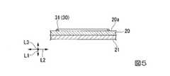
図3~図5に示すように、粗面部30は、操作面20aから突出した凸部31を備えている。
凸部31は、操作面20aから車室側に向けて厚さ方向L1に沿って膨出するように形成されている。具体的には、凸部31は、断面視で半円形状に膨出するように形成されていると共に、厚さ方向L1から見た平面視で、特定の仮想ボタン41の周囲を囲むように連続的に繋がった枠状に形成に形成されている。As shown in FIGS. 3 to 5, the
The
図示の例では、凸部31は厚さ方向L1から見た平面視で、第1方向L2に沿った長さが第2方向L3に沿った長さよりも長い長方形状に形成されている。ただし、凸部31の枠形状は、この場合に限定されるものではなく、例えば円形状、楕円状、多角形状であっても構わない。 In the illustrated example, the
上述のように構成された凸部31は、タッチパネル20とは別体に形成され、操作面20a上に組み合わされている。例えば凸部31は、所定の硬度を有する合成樹脂製とされ、操作面20a上に接着、貼着等によって一体的に組み合わされている。ただし、凸部31はタッチパネル20とは別体に形成されている必要はなく、タッチパネル20と一体に形成されていても構わない。 The
(カーナビゲーション装置の作用)
上述のように構成された触感提示デバイス3を具備するカーナビゲーション装置1を使用する場合の作用について説明する。(Action of car navigation device)
The operation of using the
この場合には、図1に示すように、タッチパネル20を通じて、表示パネル21に表示された情報を視認しながら、タッチパネル20を指先で操作することで、触れた場所に対応する操作を行うことができる。これにより、カーナビゲーション装置1が有する各種機能を適宜利用することができる。
特に、タッチパネル20を操作する際、アクチュエータ4からの振動を利用して、タッチパネル20を操作面20aの面内方向である第1方向L2に瞬間的に振動させることができる。そのため、タッチパネル20に触れた指先に対して、力学的な操作感覚を疑似的に作用させることができ、指先に対してクリック感を与えるかのような触感を与えることができる。In this case, as shown in FIG. 1, by operating the
In particular, when operating the
さらに図3に示すように、表示パネル21の表示内容を切り替えて、複数の仮想ボタン40を表示した場合、特定の仮想ボタン41を入力操作するときに、粗面部30を指先で触れながらタッチパネル20を操作することができる。このとき、粗面部30に触れた指先に対して物理的な刺激(触感)を与えることができるので、粗面部30を触れないでタッチパネル20を操作した場合に比べて、タッチパネル20の振動に伴って指先に対して大きな触感を効果的に与えることができる。従って、従来では感じ得ない、大きく且つ独特な触感を指先に与えることができる。 Furthermore, as shown in FIG. 3, when the display contents of the
上述のように、特定の仮想ボタン41を入力操作するときに、粗面部30を利用して指先に対して大きな触感を効果的に与えることができるので、特定の仮想ボタン41の入力操作と、他の仮想ボタン40の入力操作とで、指先に与える触感を異ならせることができる。従って、重要度の高い特定の仮想ボタン41を入力操作するときに、より刺激の強い触感を与えることができる。 As described above, when performing an input operation on a specific
しかも、凸部31は特定の仮想ボタン41の周囲を囲むように枠状に形成されているので、タッチパネル20を指先で触れて特定の仮想ボタン41を入力操作する際に、例えば指先をどの方向からアプローチしたとしても、凸部31に触れ易くすることができる。そのうえ、凸部31の出っ張り感を指先に対して与えることができるので、指先に対して大きな触感を効果的に与え易い。これらのことから、先に述べた作用効果をより一層顕著に奏功することができる。 Moreover, since the
以上説明したように、本実施形態のカーナビゲーション装置1によれば、操作者の指先に対して、大きく且つ独特な触感を効果的に与えることができる。従って、車両Vの振動を受けている状況下であっても、指先に対して明確な触感を与えることができる。そのため、操作性が向上したカーナビゲーション装置1として利用することができる。 As described above, according to the
さらに本実施形態では、タッチパネル20を操作面20aの面内方向である第1方向L2に振動させているので、タッチパネル20に触れた指先の腹の部分に対して、滑らすようにタッチパネル20を振動させることができるうえ、凸部31の突出方向(厚さ方向L1)に対して直交するようにタッチパネル20を振動させることができる。従って、指先に対してより効果的な触感を与えることができる。 Furthermore, in the present embodiment, the
さらに本実施形態では、タッチパネル20の操作面20a上に凸部31を接着、貼着等によって組み合わせることで粗面部30を構成しているので、構成の簡略化を図ることができると共に低コスト化を図り易い。さらに、必要に応じて凸部31の付替え等を行うことも可能であるので、例えば凸部31の位置修正や形状の異なる別の凸部31への交換等を行うことができ、使い易さを向上することができる。 Furthermore, in the present embodiment, the
以上、本発明の実施形態を説明したが、これらの実施形態は例として提示したものであり、発明の範囲を限定することは意図していない。実施形態は、その他様々な形態で実施されることが可能であり、発明の要旨を逸脱しない範囲で、種々の省略、置き換え、変更を行うことができる。実施形態やその変形例には、例えば当業者が容易に想定できるもの、実質的に同一のもの、均等の範囲のものなどが含まれる。 Although embodiments of the present invention have been described above, these embodiments are presented as examples and are not intended to limit the scope of the invention. Embodiments can be implemented in various other forms, and various omissions, replacements, and modifications can be made without departing from the scope of the invention. Embodiments and modifications thereof include, for example, those that can be easily imagined by those skilled in the art, those that are substantially the same, and those within an equivalent range.
例えば上記実施形態では、触感提示装置をカーナビゲーション装置1に適用した場合を例に挙げて説明したが、この場合に限定されるものではなく、タッチ時に指先に対して物理的な操作触感を疑似的に与える各種の電子機器等に適用しても構わない。
特に、本発明に係る触感提示装置は、振動を受け易い状況下であっても、指先に対して明確な触感を与えることができるので、操作者に装着或いは操作者が所持した状態で使用するようなウエラブル用途等に好適に利用することができる。例えば、スマートウォッチ或いはスマートフォン等の携帯情報端末に好適に利用することができる。For example, in the above embodiment, the case where the tactile sensation presentation device is applied to the
In particular, the tactile sensation presentation device according to the present invention can give a clear tactile sensation to the fingertip even in a situation where it is susceptible to vibration, so it is worn by the operator or used while being held by the operator. It can be suitably used for such wearable applications. For example, it can be suitably used for mobile information terminals such as smart watches and smartphones.
また上記実施形態では、操作面20aの面内方向である第1方向L2にタッチパネル20が振動する場合を例に挙げて説明したが、この場合に限定されるものではなく、例えば第2方向L3にタッチパネル20が直線的に振動する構成としても構わない。さらには、例えばカーナビゲーション装置1を車室側から見たときに、車両Vの左右方向に対して斜めにタッチパネル20が直線的に振動、すなわち第1方向L2及び第2方向L3の両方にベクトル成分を有するようにタッチパネル20を振動させても構わない。
さらには、タッチパネル20の振動方向は、操作面20aの面内方向に限定されるものではなく、例えば操作面20aに対して直交する方向である厚さ方向L1に振動しても構わない。In the above embodiment, the case where the
Furthermore, the vibrating direction of the
また上記実施形態では、仮想ボタン40の周囲を囲むように、連続的に繋がった枠状の凸部31を利用して粗面部30を構成したが、凸部31の形状はこの場合に限定されるものではなく、適宜変更して構わない。特に、粗面部30の形状等を工夫することで、指先に対して異なった触感を与えることが可能であるので、多様なバリエーションの触感を容易に与えることが可能である。 Further, in the above-described embodiment, the
例えば図6及び図7に示すように、操作面20aから厚さ方向L1に窪んだ凹部51によって粗面部50を構成しても構わない。
図示の例では、凹部51は断面視で半円形状に窪むように形成されていると共に、厚さ方向L1から見た平面視で、特定の仮想ボタン41の周囲を囲むように連続的に繋がった枠状に形成に形成されている。具体的には、凹部51は厚さ方向L1から見た平面視で、第1方向L2に沿った長さが第2方向L3に沿った長さよりも長い長方形状に形成されている。ただし、凹部51の枠形状は、この場合に限定されるものではなく、例えば円形状、楕円状、多角形状であっても構わない。
このように構成された粗面部50であっても、上記実施形態と同様の作用効果を奏功することができる。For example, as shown in FIGS. 6 and 7, the
In the illustrated example, the
Even with the
さらに、例えば図8及び図9に示すように、操作面20aの面内方向(第1方向L2及び第2方向L3)に間隔をあけて配置された複数の凸部61によって粗面部60を形成しても構わない。
図示の例では、複数の凸部61は、断面視で半円形状に膨出するようにそれぞれ形成されていると共に、厚さ方向L1から見た平面視で、特定の仮想ボタン41の周囲を囲むように枠状に配列されている。Further, as shown in FIGS. 8 and 9, for example, a
In the illustrated example, each of the plurality of
このように構成された粗面部60であっても、上記実施形態と同様の作用効果を奏功することができる。それに加え、タッチパネル20を指先で触れて特定の仮想ボタン41を入力操作する際に、複数の凸部61に対して指先を一度に接触させることができる。従って、指先に対する凸部61の接触箇所を増やすことができ、タッチパネル20の振動に伴って指先に対してさらに大きな触感を効果的に与えることができる。しかも、複数の凸部61は特定の仮想ボタン41の周囲を囲むように枠状に配列されているので、指先をどの方向からアプローチしたとしても、凸部61に触れ易くすることができる。従って、上述の作用効果を適切に奏功させることができる。
なお、この場合において、複数の凸部61を凹部に変更することで粗面部を構成しても構わない。この場合であっても、同様の作用効果を奏功することができる。Even with the
In this case, the rough surface portion may be configured by changing the plurality of
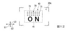
さらに、例えば図10及び図11に示すように、操作面20aの面内方向(第1方向L2及び第2方向L3)に間隔をあけてアレイ状(行列状)に配置された複数の凹部71によって粗面部70を形成しても構わない。
図示の例では、複数の凹部71は、断面視で半円形状に窪むようにそれぞれ形成されていると共に、厚さ方向L1から見た平面視で、特定の仮想ボタン41に対して厚さ方向L1に重なる位置に配列されている。Further, for example, as shown in FIGS. 10 and 11 , a plurality of
In the illustrated example, the plurality of
このように構成された粗面部70であっても、上記実施形態と同様の作用効果を奏功することができる。それに加え、タッチパネル20を指先で触れて特定の仮想ボタン41を入力操作する際に、指先を複数の凹部71に対して指先を確実に接触させることができる。従って、タッチパネル20の振動に伴って指先に対して確実に大きな触感を与えることができる。
なお、この場合において、複数の凹部71を凸部に変更することで粗面部を構成しても構わない。この場合であっても、同様の作用効果を奏功することができる。Even with the
In this case, the rough surface portion may be configured by changing the plurality of
なお、図10及び図11では、複数の凹部71を特定の仮想ボタン41に対して厚さ方向L1に重なる位置に配列したが、例えば図12に示すように、複数の凹部71を、厚さ方向L1から見た平面視で特定の仮想ボタン41から面内方向にずれた位置に配列した粗面部70としても構わない。図示の例では、複数の凹部71を、仮想ボタン40から第2方向L3にずれた位置に配列している。 10 and 11, the plurality of
このように構成された粗面部70であっても、上記実施形態と同様の作用効果を奏功することができる。それに加え、複数の凹部71が仮想ボタン40から第2方向L3にずれた位置に配列されているので、特定の仮想ボタン41の視認性を向上することができる。
なお、この場合には、例えば表示パネル21が、複数の凹部71が配列されている領域を照らすように、該領域を発光表示させても構わない。これにより、複数の凹部71を指先で触れるように、タッチを促すことができる。また、複数の凹部71を触れることで、特定の仮想ボタン41が入力操作されるように、タッチパネル20を構成すれば良い。Even with the
In this case, for example, the
また、上記実施形態では、特定の仮想ボタン41が1つの場合を例に挙げて説明したが、この場合に限定されるものではなく、特定の仮想ボタン41が複数あっても構わない。この場合には、特定の仮想ボタン41の数に対応して、粗面部30を複数設ければ良い。このとき、例えば凸部又は凹部の形状や個数等を変更することで、複数の粗面部30のそれぞれが、互いに表面粗さが異なるように構成しても構わない。
このように構成することで、同一のアクチュエータ4であっても、各粗面部30に触れた指先を、異なる振動モード(例えば振幅、周波数、パルス幅、PWM駆動時の周波数、Duty比等)で振動させることが可能である。従って、例えば特定の仮想ボタン41の内容、種類等によって、指先に与える触感を容易に異ならせることができる。Also, in the above embodiment, the case where there is one specific
By configuring in this way, even with the
L1…厚さ方向
L2…第1方向(面内方向)
L3…第2方向(面内方向)
1…カーナビゲーション装置(触感提示装置)
2…ケーシング
3…触感提示デバイス
4…アクチュエータ
5…制御部
20…タッチパネル(操作パネル)
20a…操作面
21…表示パネル
30、50、60、70…粗面部
31、61…凸部
40…仮想ボタン
43…特定タッチ領域(特定ボタン領域)
51、71…凹部L1... thickness direction L2... first direction (in-plane direction)
L3...Second direction (in-plane direction)
1... Car navigation device (tactile presentation device)
DESCRIPTION OF
20a...
51, 71... Concave part
Claims (5)
Translated fromJapanese前記操作パネルを通じて、少なくとも情報を表示する表示パネルと、を備え、
前記操作面の少なくとも一部には、前記操作面における他の部分の表面粗さよりも粗面化された粗面部が設けられ、
前記表示パネルは、複数の仮想ボタンを表示可能とされ、
前記操作面は、複数の前記仮想ボタンのうち特定の仮想ボタンを操作するための特定ボタン領域を有し、
前記粗面部は、前記特定ボタン領域に設けられ、
前記粗面部は、前記操作面から突出した凸部、又は前記操作面から窪んだ凹部のいずれか一方を備え、
前記凸部又は前記凹部は、前記操作パネルの厚さ方向から見た平面視で、前記特定の仮想ボタンの周囲を囲むように、連続的に繋がった枠状に形成されていることを特徴とする触感提示デバイス。an operation panel having an operation surface to be operated with a fingertip and vibrating momentarily at least when operated by the fingertip;
a display panel that displays at least information through the operation panel,
At least part of the operation surface is provided with a roughened surface portion having a surface roughness rougher than that of other portions of the operation surface,
The display panel is capable of displaying a plurality of virtual buttons,
The operation surface has a specific button area for operating a specific virtual button among the plurality of virtual buttons,
The rough surface portion is provided in the specific button area,
The rough surface portion includes either a convex portion protruding from the operation surface or a concave portion recessed from the operation surface,
The convex portion or the concave portion is formed in a continuously connected frame shape so as to surround the specific virtual button in a plan view seen from the thickness direction of the operation panel. haptic presentation device.
前記凸部は、前記操作パネルとは別体に形成され、前記操作面上に組み合わされている、触感提示デバイス。In the tactile sensation presentation device according to claim1 ,
The tactile sensation presentation device, wherein the convex portion is formed separately from the operation panel and combined with the operation surface.
前記操作パネルは、前記操作面の面内方向に振動する、触感提示デバイス。In the tactile sensation presentation device according to claim 1or 2 ,
The tactile sense presentation device, wherein the operation panel vibrates in an in-plane direction of the operation surface.
前記粗面部は、複数設けられ、互いに表面粗さが異なっている、触感提示デバイス。In the tactile sensation presentation device according to any one of claims1 to3 ,
The tactile sensation presenting device, wherein a plurality of the rough surface portions are provided and have different surface roughnesses.
前記触感提示デバイスに組み合わされるケーシングと、
前記ケーシング内に収容され、前記操作パネルに対して振動を与えるアクチュエータと、
前記ケーシング内に収容され、前記操作パネルの操作に応じて前記表示パネルの表示を制御する制御部と、を備えることを特徴とする触感提示装置。a tactile sense presentation device according to any one of claims 1 to4 ;
a casing combined with the tactile sensation presentation device;
an actuator housed in the casing and applying vibration to the operation panel;
A tactile sense presentation device, comprising: a control unit that is housed in the casing and that controls display on the display panel according to an operation on the operation panel.
Priority Applications (1)
| Application Number | Priority Date | Filing Date | Title |
|---|---|---|---|
| JP2019029801AJP7189046B2 (en) | 2019-02-21 | 2019-02-21 | Tactile sensation presentation device and tactile sensation presentation apparatus |
Applications Claiming Priority (1)
| Application Number | Priority Date | Filing Date | Title |
|---|---|---|---|
| JP2019029801AJP7189046B2 (en) | 2019-02-21 | 2019-02-21 | Tactile sensation presentation device and tactile sensation presentation apparatus |
Publications (2)
| Publication Number | Publication Date |
|---|---|
| JP2020135557A JP2020135557A (en) | 2020-08-31 |
| JP7189046B2true JP7189046B2 (en) | 2022-12-13 |
Family
ID=72278705
Family Applications (1)
| Application Number | Title | Priority Date | Filing Date |
|---|---|---|---|
| JP2019029801AActiveJP7189046B2 (en) | 2019-02-21 | 2019-02-21 | Tactile sensation presentation device and tactile sensation presentation apparatus |
Country Status (1)
| Country | Link |
|---|---|
| JP (1) | JP7189046B2 (en) |
Citations (4)
| Publication number | Priority date | Publication date | Assignee | Title |
|---|---|---|---|---|
| JP2004530200A (en) | 2001-03-09 | 2004-09-30 | イマージョン コーポレーション | Tactile interface for laptop computers and other portable devices |
| US20100052879A1 (en) | 2008-08-29 | 2010-03-04 | Nanos Steven G | Apparatus and Method for the Tactile Identification of Keys and Regions of a Touch-Responsive Device |
| JP2014174809A (en) | 2013-03-11 | 2014-09-22 | Univ Of Electro-Communications | Terminal device and input auxiliary sheet |
| JP2017045419A (en) | 2015-08-28 | 2017-03-02 | 富士通テン株式会社 | Input device and display device |
- 2019
- 2019-02-21JPJP2019029801Apatent/JP7189046B2/enactiveActive
Patent Citations (4)
| Publication number | Priority date | Publication date | Assignee | Title |
|---|---|---|---|---|
| JP2004530200A (en) | 2001-03-09 | 2004-09-30 | イマージョン コーポレーション | Tactile interface for laptop computers and other portable devices |
| US20100052879A1 (en) | 2008-08-29 | 2010-03-04 | Nanos Steven G | Apparatus and Method for the Tactile Identification of Keys and Regions of a Touch-Responsive Device |
| JP2014174809A (en) | 2013-03-11 | 2014-09-22 | Univ Of Electro-Communications | Terminal device and input auxiliary sheet |
| JP2017045419A (en) | 2015-08-28 | 2017-03-02 | 富士通テン株式会社 | Input device and display device |
Also Published As
| Publication number | Publication date |
|---|---|
| JP2020135557A (en) | 2020-08-31 |
Similar Documents
| Publication | Publication Date | Title |
|---|---|---|
| US9983672B2 (en) | Electrostatic haptic actuator and user interface with an electrostatic haptic actuator | |
| JP6078935B2 (en) | Electronics | |
| EP2889726B1 (en) | Systems and methods for controlling multiple displays with single controller and haptic enabled user interface | |
| JP6147656B2 (en) | Input device | |
| JP5390029B2 (en) | Electronics | |
| JP5884090B2 (en) | Method for presenting information and electronic device | |
| JP2017151638A (en) | Control unit for vehicle and control method thereof | |
| WO2015136923A1 (en) | Electronic device | |
| CN109564469B (en) | Display operation device | |
| JP2018036818A (en) | Input device | |
| JP7189046B2 (en) | Tactile sensation presentation device and tactile sensation presentation apparatus | |
| JP2014081716A (en) | Force feedback device and user interface system | |
| WO2019163196A1 (en) | Haptic sensation presentation device and haptic sensation presentation method | |
| JP2017199200A (en) | Touch manipulation device | |
| US20200142489A1 (en) | Input device | |
| KR20160075019A (en) | Display device | |
| JP2018160244A (en) | Haptic effect using high bandwidth thin actuation system | |
| CN111596755B (en) | Vibration generating device and touch feeling presenting device | |
| JP6809868B2 (en) | Movement guidance device, panel device, control device and movement guidance method | |
| JP6941798B2 (en) | Input device | |
| WO2019044371A1 (en) | Input device | |
| US12073069B2 (en) | Control value setting device and control value setting program | |
| JP2018147394A (en) | Input device | |
| KR20160080751A (en) | Haptic display device and method for driving the same | |
| JP2021047897A (en) | Movement guidance device and movement guidance method |
Legal Events
| Date | Code | Title | Description |
|---|---|---|---|
| A621 | Written request for application examination | Free format text:JAPANESE INTERMEDIATE CODE: A621 Effective date:20211207 | |
| A977 | Report on retrieval | Free format text:JAPANESE INTERMEDIATE CODE: A971007 Effective date:20220914 | |
| A131 | Notification of reasons for refusal | Free format text:JAPANESE INTERMEDIATE CODE: A131 Effective date:20221011 | |
| A521 | Request for written amendment filed | Free format text:JAPANESE INTERMEDIATE CODE: A523 Effective date:20221110 | |
| TRDD | Decision of grant or rejection written | ||
| A01 | Written decision to grant a patent or to grant a registration (utility model) | Free format text:JAPANESE INTERMEDIATE CODE: A01 Effective date:20221122 | |
| A61 | First payment of annual fees (during grant procedure) | Free format text:JAPANESE INTERMEDIATE CODE: A61 Effective date:20221201 | |
| R150 | Certificate of patent or registration of utility model | Ref document number:7189046 Country of ref document:JP Free format text:JAPANESE INTERMEDIATE CODE: R150 |