JP7187875B2 - Information processing device, system, moving object, information processing method and program - Google Patents
Information processing device, system, moving object, information processing method and programDownload PDFInfo
- Publication number
- JP7187875B2 JP7187875B2JP2018147868AJP2018147868AJP7187875B2JP 7187875 B2JP7187875 B2JP 7187875B2JP 2018147868 AJP2018147868 AJP 2018147868AJP 2018147868 AJP2018147868 AJP 2018147868AJP 7187875 B2JP7187875 B2JP 7187875B2
- Authority
- JP
- Japan
- Prior art keywords
- pixel
- pixels
- distance
- parallax
- map
- Prior art date
- Legal status (The legal status is an assumption and is not a legal conclusion. Google has not performed a legal analysis and makes no representation as to the accuracy of the status listed.)
- Active
Links
Images


Classifications
- G—PHYSICS
- G06—COMPUTING OR CALCULATING; COUNTING
- G06V—IMAGE OR VIDEO RECOGNITION OR UNDERSTANDING
- G06V20/00—Scenes; Scene-specific elements
- G06V20/50—Context or environment of the image
- G06V20/56—Context or environment of the image exterior to a vehicle by using sensors mounted on the vehicle
- G06V20/58—Recognition of moving objects or obstacles, e.g. vehicles or pedestrians; Recognition of traffic objects, e.g. traffic signs, traffic lights or roads
Landscapes
- Engineering & Computer Science (AREA)
- Physics & Mathematics (AREA)
- General Physics & Mathematics (AREA)
- Multimedia (AREA)
- Theoretical Computer Science (AREA)
- Image Analysis (AREA)
- Measurement Of Optical Distance (AREA)
- Traffic Control Systems (AREA)
Description
Translated fromJapanese本発明は、情報処理装置、システム、移動体、情報処理方法およびプログラムに関する。 The present invention relates to an information processing device, system, mobile object, information processing method, and program.
従来、自動車の安全性において、歩行者と自動車とが衝突したときに、いかに歩行者を守れるか、および、乗員を保護できるかの観点から、自動車のボディー構造等の開発が行われてきた。しかしながら、近年、情報処理技術および画像処理技術の発達により、高速に人および自動車を検知する技術が開発されてきている。これらの技術を応用して、自動車が物体に衝突する前に自動的にブレーキをかけ、衝突を未然に防ぐという自動車も既に開発されている。また、安全性能に加えてドライバーの運転時の負荷を軽減するため、前方車両を認識して、自動で追従する制御機能(ACC:Adaptive Cruise Control)も既に車載システムとして発売されている。 2. Description of the Related Art Conventionally, in terms of automobile safety, automobile body structures and the like have been developed from the viewpoint of how pedestrians and occupants can be protected when pedestrians and automobiles collide. However, in recent years, with the development of information processing technology and image processing technology, technology for detecting people and automobiles at high speed has been developed. By applying these technologies, automobiles have already been developed that automatically brake before they collide with an object to prevent collisions. In addition to safety performance, a control function (ACC: Adaptive Cruise Control) that recognizes the vehicle in front and automatically follows it has already been released as an in-vehicle system in order to reduce the burden on the driver while driving.
これらの制御を実現するためには、自車から前方に存在する物体までの距離を正確に測定する必要があり、そのために、ミリ波レーダ、レーザレーダによる測距、ステレオカメラによる測距などが既に採用されている。車載用画像認識技術による自動車の自動制御を実用化するには、上記装置で計測した距離情報に基づき、画面上に写る物体を認識し、物体ごとに制御を行う必要がある。例えば、検知物体が歩行者か車両かによって制御を変えることが想定される。 In order to realize these controls, it is necessary to accurately measure the distance from the vehicle to an object in front of it. Already adopted. In order to put into practical use the automatic control of automobiles using in-vehicle image recognition technology, it is necessary to recognize objects appearing on the screen based on the distance information measured by the above device, and to control each object. For example, it is assumed that the control is changed depending on whether the detected object is a pedestrian or a vehicle.
例えばステレオカメラで測距する場合、左右のカメラで撮影された局所領域のズレ量に基づいて視差画像(距離画像の一例)を生成することで、画像中の画素ごとに距離を測定することができる。この視差画像を用いて物体検知を行う場合は、まず、視差画像中の各画素を、横軸を視差値(距離)、縦軸を視差画像のy座標としたマップ(Vマップ:V-Disparity Map)上に投票し、マップ上の分布形状から路面形状を推定する。次に、視差画像中の画素のうち、推定した路面よりも高い位置に存在する画素のみを、横軸を視差画像のx座標、縦軸を視差値としたマップ(Uマップ:U-Disparity Map)に投票する。そして、U-Disparity Map上の同程度の視差値が高密度で集まる領域(視差塊)を物体として検知する。 For example, when measuring a distance with a stereo camera, it is possible to measure the distance for each pixel in the image by generating a parallax image (an example of a distance image) based on the amount of deviation between local areas captured by the left and right cameras. can. When performing object detection using this parallax image, first, each pixel in the parallax image is mapped (V map: V-Disparity Map) and estimate the road surface shape from the distribution shape on the map. Next, among the pixels in the parallax image, only the pixels that exist at a position higher than the estimated road surface are mapped (U map: U-Disparity Map ). Then, an area (parallax mass) where similar parallax values gather at a high density on the U-Disparity Map is detected as an object.
以上の方法で物体を検知する場合、各マップを生成する際に視差画像や他のマップにアクセスする必要があるために多くの処理時間を要するという問題がある。そこで、視差画像を間引いてアクセスする方法が知られている(例えば特許文献1参照)。 When detecting an object by the above method, there is a problem that a lot of processing time is required because it is necessary to access parallax images and other maps when generating each map. Therefore, a method of thinning out parallax images for access is known (see, for example, Patent Document 1).
上記従来技術のように、アクセスする画素を間引いて画素へのアクセス数を削減することにより、処理速度を向上させることができる。しかしながら、画素へのアクセス数の減少は、路面や路面上の物体(他車両、歩行者、道路設備等)の検知精度を低下させる可能性がある。このように、処理速度と検知精度とはトレードオフの関係にある。 By thinning out the pixels to be accessed to reduce the number of accesses to the pixels, as in the conventional technique described above, the processing speed can be improved. However, a decrease in the number of accesses to pixels may reduce the detection accuracy of the road surface and objects on the road surface (other vehicles, pedestrians, road facilities, etc.). Thus, there is a trade-off relationship between processing speed and detection accuracy.
本発明は、上記に鑑みてなされたものであって、処理速度と検知精度とのトレードオフを制御可能な情報処理装置、システム、移動体、情報処理方法およびプログラムを提供することを目的とする。 SUMMARY OF THE INVENTION It is an object of the present invention to provide an information processing apparatus, system, mobile object, information processing method, and program capable of controlling the trade-off between processing speed and detection accuracy. .
上述した課題を解決し、目的を達成するために、本発明の一形態は、画素毎に距離情報を有する視差画像を取得する取得部と、前記取得部により取得された前記視差画像の前記画素にアクセスすることにより取得した前記距離情報に基づいてデータを生成するデータ生成部と、を備え、前記データ生成部は、前記視差画像に基づいて取得した前記距離情報が示す距離が遠いほど前記画素へのアクセス数が増加するように、且つ前記距離が近いほど前記アクセス数が減少するように、前記アクセス数を変化させるパラメータを設定する、ことを特徴とする情報処理装置である。
In order to solve the above-described problems and achieve the object, one aspect of the present invention provides anacquisition unit that acquires aparallax image having distance information for each pixel; and a data generation unit that generates data based on the distance information obtained by accessing theparallax image, the data generation unit generates the pixels as the distance indicated by the distance information obtained based on the parallax image increases. and a parameter for changing the number of accesses is set so that the number of accesses to is increased and the number of accesses is decreased as the distance is shorter.
本発明によれば、処理速度と検知精度とのトレードオフを制御することが可能となる。 According to the present invention, it is possible to control the trade-off between processing speed and detection accuracy.
以下、添付図面を参照しながら、本発明に係る情報処理装置、システム、移動体、情報処理方法およびプログラムの実施形態を詳細に説明する。 Exemplary embodiments of an information processing apparatus, a system, a mobile object, an information processing method, and a program according to the present invention will be described in detail below with reference to the accompanying drawings.
(第1の実施形態)
図1は、第1の実施形態に係る機器制御システム1(「システム」の一例)を搭載した車両10(「移動体」の一例)の例を示す模式図である。本実施形態に係る車両10のフロントガラスの上部(バックミラー付近)には、撮像ユニット11が設置されている。撮像ユニット11は、車両10の進行方向17前方を撮像するステレオカメラと、ステレオカメラが撮像した撮像画像を解析する解析ユニット(「情報処理装置」の一例)と、を含む。ステレオカメラは、水平に配置された2つのカメラ部により、左側視界15の撮像画像および右側視界16の撮像画像を取得する(以下、「画像を取得する」という表現は「画像データを取得する」と同義として用いられる)。解析ユニットは、ステレオカメラから供給される左右の撮像画像に基づいて、車両10が走行中の路面、前方車両、歩行者、障害物等の認識対象物を解析する。また、車両10には、解析ユニットの解析結果(情報処理装置による情報処理の結果)に基づく制御(各種車載機器の制御、車両10のハンドル制御又はブレーキ制御等)を行う車両ECU(「制御装置」の一例)などが搭載されている。(First embodiment)
FIG. 1 is a schematic diagram showing an example of a vehicle 10 (an example of a “moving body”) equipped with a device control system 1 (an example of a “system”) according to the first embodiment. An
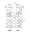
図2は、第1の実施形態に係る機器制御システム1の全体的なハードウェア構成の例を示す図である。機器制御システム1は、撮像ユニット11および車両ECU(Engine Control Unit)51を含む。車両ECU51は、車両10の走行状態を制御する信号を生成する回路を含むユニットであり、プログラムが記憶されたメモリ、プログラムにより所定の演算制御処理を行うCPU(Central Processing Unit)、各種ロジック回路等を利用して構成される。車両ECU51は、撮像ユニット11に含まれる解析ユニットの解析結果に基づいて、車両10の制御、例えばブレーキ、アクセル、操舵等の自動制御、警告の出力等を行うための処理を行う。 FIG. 2 is a diagram showing an example of the overall hardware configuration of the
図3は、第1の実施形態に係る撮像ユニット11のハードウェア構成の例を示す図である。本実施形態に係る撮像ユニット11は、ステレオカメラ12および画像解析ユニット13を含む。 FIG. 3 is a diagram showing an example of the hardware configuration of the
ステレオカメラ12は、左目用となる第1のカメラ部21aと、右目用となる第2のカメラ部21bとが平行に組み付けられて構成されている。両カメラ部21a,21bは、それぞれレンズ22、画像センサ23、およびセンサコントローラ24を含む。画像センサ23は、例えばCCD(Charge Coupled Device)、CMOS(Complementary Metal-Oxide Semiconductor)等である。センサコントローラ24は、画像センサ23の露光制御、画像読み出し制御、外部回路との通信、画像データの送信制御等を行うための回路を含むデバイスである。 The
画像解析ユニット13は、「情報処理装置」の一例であり、画素毎に距離情報を有する距離画像を取得し、その取得した距離画像に基づくデータを生成する。ここでは、距離画像の一例として、画素毎に視差値を有する視差画像を例に挙げて説明するが、これに限られるものでは無く、例えば画素ごとに、ミリ波レーダやLIDARなどで算出された距離計測値を有する画像や、画像ごとに、視差値と距離計測値との組み合わせを有する画像を距離画像として用いることもできる。また、詳しくは後述するが、ここでは、距離画像に基づくデータの一例として、VマップとUマップを例に挙げて説明するが、これに限られるものでは無い。画像解析ユニット13が有する機能の詳細については後述する。 The
画像解析ユニット13のハードウェア構成について説明する。図3に示すように、画像解析ユニット13は、CPU31、FPGA(Field-Programmable Gate Array)32、ROM(Read Only Memory)33、RAM(Random Access Memory)34、シリアルIF(Interface)35、データIF36、データバスライン41、およびシリアルバスライン42を含む。 A hardware configuration of the
ステレオカメラ12は、データバスライン41およびシリアルバスライン42を介して画像解析ユニット13と接続している。CPU31は、ROM33に記憶されたプログラムに従って、画像解析ユニット13全体の動作、画像処理、画像認識処理等を実行するための処理を行う。両カメラ部21a,21bの画像センサ23により取得された輝度データ(画素毎に輝度値が設定された輝度画像)は、データバスライン41を介して画像解析ユニット13のRAM34に書き込まれる。CPU31またはFPGA32からのセンサ露光値の変更制御データ、画像読み出しパラメータの変更制御データ、各種設定データ等は、シリアルバスライン42を介してセンサコントローラ24との間で送受信される。
FPGA32は、RAM34に保存されたデータに対してリアルタイム性が要求される処理を行う。リアルタイム性が要求される処理とは、例えばガンマ補正、ゆがみ補正(左右画像の平行化)、ブロックマッチングによる視差演算等を行うことにより、輝度画像から、画素毎に視差値が設定された視差画像を生成する処理等である。このように生成された視差画像は、RAM34に再度書き込まれる。 The
CPU31は、ステレオカメラ12の各センサコントローラ24の制御、および画像解析ユニット13の全体的な制御を行う。ROM33には、CPU31またはFPGA32に各種処理を実行させるプログラムが格納されている。CPU31は、データIF36を介して、例えば車両10のCAN(Controller Area Network)情報(車速、加速度、舵角、ヨーレート等)をパラメータとして取得する。CPU31は、ROM33に記憶されているプログラムに従って、RAM34に記憶されている輝度画像および視差画像を用いて、路面形状の推定、オブジェクトの認識、距離の計測等の各種処理を実行する。 The
画像解析ユニット13による解析結果を示す解析データは、シリアルIF35を介して、例えば自動ブレーキシステム、自動速度制御システム、自動操舵システム、警報システム等の外部システムへ供給される。 Analysis data indicating analysis results by the
図4は、第1の実施形態に係る機器制御システム1の機能構成の例を示す図である。本実施形態に係る機器制御システム1は、撮像部101、視差計算部102、Vマップ生成部103、路面推定部104、Uマップ生成部105、クラスタリング部106、棄却部107、トラッキング部108、および制御部109を含む。図4は、撮像ユニット11による1フレームの撮像から路面推定、オブジェクト認識等を含む画像解析処理を終え、車両制御を開始させるまでの一連の流れの例を示している。 FIG. 4 is a diagram showing an example of the functional configuration of the
撮像部101は、車両10前方を撮像し、2つの輝度画像(撮像画像)を取得する機能部である。撮像部101は、撮像ユニット11等により構成される。撮像部101により取得された2つの輝度画像の一方(例えば第1のカメラ部21aにより取得された左側視界15の輝度画像)が基準画像となり、他方(例えば第2のカメラ部21bにより取得された右側視界16の輝度画像)が比較画像となる。 The
視差計算部102は、基準画像の輝度画像と比較画像の輝度画像とを用いて、ステレオカメラ12の撮像範囲内の局所領域のブロックマッチング等により画素毎の視差値を算出し、視差画像を生成する機能部である。視差計算部102は、例えばFPGA32、CPU31等により構成される。 The parallax calculation unit 102 uses the luminance image of the reference image and the luminance image of the comparison image to calculate the parallax value for each pixel by block matching or the like of the local area within the imaging range of the
Vマップ生成部103は、視差計算部102により生成された視差画像を用いて、後段の路面推定部104で使用するためのVマップを生成する。Vマップは、「第1のマップ」の一例であり、視差画像(「距離画像」の一例)の垂直方向の位置と、視差値d(「距離情報」の一例)との関係を示すマップである。より具体的には、Vマップは、横軸に視差値d、縦軸に視差画像のy座標を対応させた二次元マップであり、視差画像の各座標(x,y)の視差値dが、Vマップ上の対応する位置(d,y)に投票されて生成される。Vマップ上の座標(d,y)には、この位置に投票された視差値dの頻度(点数)を示す値(頻度値)が格納される。 The V
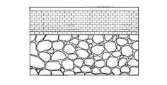
図5は、視差画像とVマップとの関係を説明するための図である。図5に示すように、Vマップの横方向の1ライン(水平ライン)上に投票される視差は、視差画像中の所定の横方向の1ラインから抽出された視差になる。なお、図5の例では、視差画像とVマップのy座標を一致させているが、必ずしもこうなっている必要はない。この関係に基づくと、視差画像中の物体は、自車から同距離に存在するため、Vマップ上では縦方向に分布(同程度の視差値d(横軸の座標)に対応して分布)することとなる。また、視差値dは距離が近方ほど大きな値となり、遠方ほど小さな値となるという特徴がある。従って、Vマップを図5のように左上原点とした場合、視差画像中の各画素(視差値d)をVマップ上に投票すると、視差値dの分布を示す形状は左上上がりとなる。後段の路面推定部104による路面形状の推定は、Vマップを用いて実施し、推定後は視差値dにおける路面高さに対応するy座標を決定することができる。図5に示す符号1030は、図5に示すVマップ上で路面形状を推定した結果を示す。ここで、前方車両の視差Pにおける路面からの高さは図中の関係となる。そのため、このy座標差(前方車両の視差Pに対応するy座標と、視差Pにおける路面高さに対応するy座標との差)が路面からの高さとなる。 FIG. 5 is a diagram for explaining the relationship between the parallax image and the V map. As shown in FIG. 5, the parallax voted on one horizontal line (horizontal line) of the V map is the parallax extracted from one predetermined horizontal line in the parallax image. In the example of FIG. 5, the y-coordinates of the parallax image and the V map are matched, but this need not necessarily be the case. Based on this relationship, the object in the parallax image exists at the same distance from the vehicle, so it is distributed in the vertical direction on the V map (distributed corresponding to the same parallax value d (horizontal axis coordinate)) It will be done. Further, the parallax value d has a characteristic that the closer the distance is, the larger the value is, and the farther the distance is, the smaller the value is. Therefore, when the V map has the upper left origin as shown in FIG. 5, when each pixel (parallax value d) in the parallax image is voted on the V map, the shape indicating the distribution of the parallax value d is upward to the upper left. The estimation of the road surface shape by the road
本実施形態では、Vマップ生成部103は、視差画像(「距離画像」の一例)を間引きながら複数の画素の各々に対してアクセス(順番にアクセス)し、アクセス対象の画素を示すアクセス画素の視差値dに基づいて、アクセスしない画素を示す未アクセス画素の視差値dを決定し、その決定した視差値dを用いてVマップ(「距離画像に基づくデータ」の一例)を生成する。詳細な内容については後述する。なお、Vマップ生成部103の機能は、CPU31がプログラムを実行することにより実現されるが、これに限らず、例えば専用のハードウェア回路(例えばFPGA32等)で実現されてもよい。 In this embodiment, the V
図4に戻って説明を続ける。路面推定部104は、Vマップ生成部103により生成されるVマップに基づいて路面形状の推定を行う。Vマップの生成方法については後述する。路面推定部104は、例えばCPU31、FPGA32等により構成される。 Returning to FIG. 4, the description continues. A road
Uマップ生成部105は、視差計算部102により生成された視差画像と、路面推定部104による路面形状の推定結果とを用いて、後段のクラスタリング部106で使用するためのUマップを生成する。Uマップは、「第2のマップ」の一例であり、視差画像(距離画像)の水平方向の位置と、路面の高さを超える視差値d(距離)との関係を示す。より具体的には、Uマップは、横軸に視差画像のx座標、縦軸に視差値dを対応させた二次元マップであり、視差画像の各座標(x,y)の視差値dのうち路面高さを超える視差値dが、Uマップ上の対応する位置(x,d)に投票されて生成される。Uマップ上の座標(x,d)には、この位置に投票された視差値dの頻度(点数)を示す値(頻度値)が格納される。 The
図6は、視差画像とUマップとの関係を説明するための図である。このUマップには、視差画像中の画素のうち、路面よりも高い視差を有する画素のみが投票されている。また、視差画像の横軸とUマップの横軸は一致しているものとする。なお、Uマップの横軸は、視差画像の横方向の座標を実距離に換算した形態であってもよいし、Uマップ上の座標に頻度値ではなく路面からの実高さを格納する形態とすることも可能であるが、Uマップの種類は任意であり、この例では、横軸を視差画像中のx座標と対応させ、各座標には頻度値を格納するものとする。物体検知は、このマップ上の視差の塊を見つける処理に該当する。図6の例では、側壁2面分と前方車両が物体として検知される。 FIG. 6 is a diagram for explaining the relationship between the parallax image and the U map. Among the pixels in the parallax image, only pixels having a higher parallax than the road surface are voted in this U map. It is also assumed that the horizontal axis of the parallax image and the horizontal axis of the U map match. Note that the horizontal axis of the U map may be in the form of converting the horizontal coordinates of the parallax image into actual distances, or in the form of storing the actual height from the road surface instead of the frequency value in the coordinates on the U map. However, any type of U-map can be used. In this example, the horizontal axis corresponds to the x-coordinate in the parallax image, and each coordinate stores a frequency value. Object detection corresponds to the process of finding disparity clusters on this map. In the example of FIG. 6, two side walls and the preceding vehicle are detected as objects.
本実施形態では、Uマップ生成部105は、視差画像を間引きながら複数の画素の各々に対してアクセスし、アクセス画素の視差値dに基づいて、アクセスしない画素を示す未アクセス画素の視差値dを決定し、その決定した視差値dを用いてUマップを生成する。詳細な内容については後述する。なお、Uマップ生成部105の機能は、CPU31がプログラムを実行することにより実現されるが、これに限らず、例えば専用のハードウェア回路(例えばFPGA32等)で実現されてもよい。 In this embodiment, the
なお、以下の説明では、VマップとUマップを区別しない場合は、単に「ディスパリティマップ」と称する場合がある。このディスパリティマップは、距離画像(この例では視差画像)に基づくデータの一例である。 In the following description, when the V map and the U map are not distinguished from each other, they may simply be referred to as "disparity maps". This disparity map is an example of data based on a distance image (parallax image in this example).
図4に戻って説明を続ける。クラスタリング部106は、Uマップ生成部105により生成されたUマップ上において、頻度値が所定値よりも多い視差値が密集している領域を新規オブジェクトとして検知し、検知された領域の輝度画像上の座標、サイズ等に基づいてオブジェクトのタイプ(人、車両、ガードレール等)を推定し、タイプを示す個体情報を付与する。クラスタリング部106は、例えばCPU31、FPGA32等により構成される。 Returning to FIG. 4, the description continues. The
棄却部107は、フレーム情報(輝度画像、視差画像等)、Uマップ、新規オブジェクトの個体情報等を用いて、検知されたオブジェクトのうち認識対象(衝突回避等の対象)でないものを棄却する処理を行う機能部である。棄却部107は、例えばCPU31、FPGA32等により構成される。 The
トラッキング部108は、検知されたオブジェクト(棄却されなかったオブジェクト)が複数のフレームで連続して出現する場合に、そのオブジェクトが追跡対象であるか否かを判定し、追跡対象である場合には追跡対象であることを示す個体情報を生成する処理を行う機能部である。トラッキング部108は、例えばCPU31,FPGA32等により構成される。
制御部109は、上記処理で得られた結果に基づき、車両10を制御(衝突回避行動、警告の出力等)する機能部である。制御部109は、例えば車両ECU51等により構成される。 The
次に、ディスパリティマップの具体的な生成方法について説明する。本実施形態のVマップ生成部103またはUマップ生成部105は、ディスパリティマップを生成する際に、視差画像を間引きながら複数の画素の各々に対して順番にアクセスし、第1のアクセス画素(着目したアクセス画素)と、その次にアクセスする第2のアクセス画素との間に存在する未アクセス画素の視差値dを、該第1のアクセス画素の視差値dと同じ値に決定して投票する。以下では、このようにアクセス画素の視差値dを基に未アクセス画素の視差値dを決定(推定)して投票する方式を、「仮想投票方式」と称する場合がある。 Next, a specific method of generating a disparity map will be described. When generating the disparity map, the V
図7は、画素の間引きについて説明するための図である。例えばx方向の間引き幅が4、y方向の間引き幅が2の場合、x方向においてアクセス画素の間に存在する未アクセス画素の数は3、y方向においてアクセス画素の間に存在する未アクセス画素の数は1となる。このとき、間引かれた未アクセス画素を間引き画素と定義する。以降では、間引かれない画素(アクセス対象の画素)を「アクセス画素」、間引かれた画素(未アクセス画素)を「間引き画素」と称する場合がある。 FIG. 7 is a diagram for explaining pixel thinning. For example, if the thinning width in the x direction is 4 and the thinning width in the y direction is 2, the number of unaccessed pixels existing between the accessed pixels in the x direction is 3, and the unaccessed pixels existing between the accessed pixels in the y direction. number is 1. At this time, the thinned non-access pixels are defined as thinned pixels. Hereinafter, pixels that are not thinned (pixels to be accessed) may be referred to as "access pixels", and pixels that have been thinned (unaccessed pixels) may be referred to as "thinned pixels".
ここで、ディスパリティマップを生成する際に、全ての画素にアクセスして投票する方式を全画素投票方式と称する。この方式では仮想投票方式や後述の単純間引き方式に比べて処理時間は最遅であるが、情報欠損は発生しない。また、ディスパリティマップを生成する際に、アクセス画素のみを投票し、間引き画素は投票しない方式を単純間引き方式と称する。この方式では全画素投票方式や仮想投票方式に比べて処理時間は最速であるが、情報欠損が生じるため物体の検知精度が低下してしまう。 Here, when generating a disparity map, a method in which all pixels are accessed and voted is called an all-pixel voting method. In this method, the processing time is the slowest compared to the virtual voting method and the simple thinning method described later, but information loss does not occur. Also, when generating a disparity map, a method in which only access pixels are voted and thinned pixels are not voted is called a simple thinning method. In this method, the processing time is the fastest compared to the all-pixel voting method and the virtual voting method, but the accuracy of object detection decreases due to information loss.
これに対して、本実施形態の仮想投票方式では、ディスパリティマップを生成する際に、所定の間引き幅で間引くものの、アクセス画素の視差値dを基に間引き画素の視差値dを推定し、アクセス画素と間引き画素を合わせて投票するので、視差画像へのアクセスを減らしつつ、ディスパリティマップ上の有効視差点数を増加させることができる。これにより、処理時間を短縮しつつ物体の検知精度の低下を抑制できる。 On the other hand, in the virtual voting method of the present embodiment, when generating the disparity map, thinning is performed with a predetermined thinning width, but the parallax value d of the thinned pixel is estimated based on the parallax value d of the access pixel, Since the access pixels and the thinned pixels are voted together, it is possible to increase the number of effective parallax points on the disparity map while reducing access to the parallax images. As a result, it is possible to suppress deterioration in object detection accuracy while shortening the processing time.
この仮想投票方式では、視差画像(距離画像)の場合、画像中の着目画素の周辺は同じ被写体の画素である確率が高いため、近い画素値になる確率も高いことを前提とする。例えば輝度画像の場合は、被写体のテクスチャなどにより、着目画素の周辺が模様の境界に該当すると画素値は大きく変化することになる。しかしながら、視差画像(距離画像)の場合はテクスチャに関係なく同じ物体の画素値は同程度の距離になり易いため、より上記前提が成立し易い。この前提の下、視差画像に基づくディスパリティマップを生成する場合は、例えば着目画素の右隣の画素に対しては、実際にアクセスしなくても同じ画素とみなして投票しても、概ね良好な視差値dを投票することができる(多少の微変化はあっても)。左右方向に限らず、上下、斜め方向に関しても同様である。つまり、仮想投票方式では、視差画像中の着目画素とその近傍画素は近い視差値dになっている可能性が高いことに着目し、アクセス画素の視差値dを基に、その近傍の間引き画素の視差値dを決定(推定)し、アクセス画素と間引き画素を合わせて投票している。これにより、処理時間を短縮しつつも有効な投票点数を増やすことができる。 In this virtual voting method, in the case of a parallax image (distance image), it is premised that there is a high probability that the pixels surrounding the target pixel in the image are pixels of the same object, and therefore the probability that the pixel values are close to each other is also high. For example, in the case of a luminance image, the pixel value will change greatly if the periphery of the target pixel corresponds to the boundary of the pattern due to the texture of the subject. However, in the case of a parallax image (distance image), the pixel values of the same object tend to be at approximately the same distance regardless of the texture, so the above premise is more likely to hold. Under this premise, when generating a disparity map based on a parallax image, for example, the pixel to the right of the pixel of interest is generally good even if it is considered the same pixel and voted without actually accessing it. disparity value d can be voted (albeit with some minor changes). The same applies not only to the horizontal direction but also to the vertical and oblique directions. In other words, in the virtual voting method, focusing on the fact that the pixel of interest in the parallax image and its neighboring pixels are likely to have similar parallax values d, based on the parallax value d of the access pixel, thinned pixels is determined (estimated), and the access pixels and the thinned pixels are voted together. As a result, it is possible to increase the effective number of voting points while shortening the processing time.
以下、Uマップを例に挙げて本実施形態の仮想投票方式について説明する。図8は、Uマップにおける横方向の全画素投票方式と、本実施形態の仮想投票方式との差異を説明するための図である。図8(A)に示すように、視差画像中の着目画素をアクセス画素αとし、次にアクセスする画素β(アクセス画素β)までの投票を考える。なお、この例では、画素へのアクセス順序は左上を始点として右方向に処理していき、1ラインにおける処理が完了すると下方向のラインに進み、そのライン中のアクセス画素に対するアクセスを左端から右方向に向かって順番に行うことになるが、これに限らず、アクセス順序は任意である。例えば下から上に向かって着目するラインを変えていく形態であってもよい。なお、図8の例では、アクセス画素αの視差値dを150、アクセス画素αの右隣の間引き画素の視差値dを145、その右隣の間引き画素の視差値dを140、さらにその右隣の間引き画素の視差値dを135とする。 The virtual voting method of the present embodiment will be described below using the U map as an example. FIG. 8 is a diagram for explaining the difference between the horizontal all-pixel voting method in the U map and the virtual voting method of the present embodiment. As shown in FIG. 8A, a pixel of interest in a parallax image is assumed to be an access pixel α, and voting up to a pixel β to be accessed next (access pixel β) is considered. In this example, the access order to the pixels starts from the upper left corner and proceeds to the right. Although the accesses are performed in order in the direction, the order of access is not limited to this and is arbitrary. For example, it may be possible to change the line of interest from bottom to top. In the example of FIG. 8, the parallax value d of the access pixel α is 150, the parallax value d of the thinned pixel adjacent to the right of the access pixel α is 145, and the parallax value d of the thinned pixel adjacent to the right is 140. Assume that the parallax value d of the adjacent thinned pixel is 135.
ここで、全画素投票方式では、アクセス画素αからアクセス画素βまでの区間に存在する間引き画素3つ分に対し、実際にアクセスしてUマップ上に投票する。この場合、投票後のUマップは図8(B)のようになる。 Here, in the all-pixel voting method, three thinned pixels existing in the section from the access pixel α to the access pixel β are actually accessed and voted on the U map. In this case, the U map after voting becomes as shown in FIG. 8(B).
これに対して、本実施形態の仮想投票方式では、上記3つの間引き画素は着目画素(アクセス画素α)の近傍の画素であるため、アクセス画素αと同じ画素値(視差値d)であるとみなして(推定して)、投票位置のみを変えて投票する。この場合、投票後のUマップは図8(C)のようになる。図8(B)に比べて誤差はあるものの、概ね良好な視差値dが投票されていると言える。 On the other hand, in the virtual voting method of the present embodiment, the three thinned pixels are pixels in the vicinity of the target pixel (access pixel α). Consider (estimate) and vote by changing only the voting position. In this case, the U map after voting becomes as shown in FIG. 8(C). Although there is an error compared to FIG. 8B, it can be said that generally favorable parallax values d are voted.
このように本実施形態の仮想投票方式を採用することで、間引き画素にアクセスすることなく、有効であると想定される視差値を決定してUマップ上に投票することができるので、Uマップ上の有効視差点数が増加し、検知精度を向上させることができる。 By adopting the virtual voting method of the present embodiment in this way, it is possible to determine a parallax value assumed to be effective and vote on the U map without accessing the thinned pixels. The number of upper effective parallax points increases, and detection accuracy can be improved.
なお、ここでは、着目したアクセス画素αと、その次にアクセスするアクセス画素βとの間に存在する3つの間引き画素全てを仮想投票したが、これに限らず、例えば3つよりも少ない数の間引き画素を仮想投票する形態であってもよい。例えば間引き幅が大きい場合、全ての間引き画素を仮想投票すると、推定された視差値d(実際とは異なる値を示す可能性がある視差値d)を割り当てられた多数の画素がUマップに投票されることになるため、検知精度に悪影響を及ぼす可能性がある。 Here, virtual voting is performed for all three thinning pixels existing between the access pixel α of interest and the access pixel β to be accessed next. A form of virtual voting for thinned pixels may be used. For example, when the decimation width is large, if all the decimated pixels are virtually voted, a large number of pixels assigned the estimated disparity value d (disparity value d that may indicate a different value than the actual value) are voted in the U map. This may have a negative impact on detection accuracy.
要するに、本発明が適用される仮想投票方式は、第1のアクセス画素(この例ではアクセス画素α)と、その次にアクセスする第2のアクセス画素(この例ではアクセス画素β)との間に存在する1以上の未アクセス画素(間引き画素)の視差値d(「距離情報」の一例)を、該第1のアクセス画素の視差値dと同じ値に決定して投票する形態であればよい。 In short, the virtual voting scheme to which the present invention applies is that between a first access pixel (access pixel α in this example) and a second access pixel to be accessed next (access pixel β in this example), The parallax value d (an example of “distance information”) of one or more non-accessed pixels (thinned pixels) existing may be set to the same value as the parallax value d of the first accessed pixel and voted. .
また、横方向だけではなく、図9に示すように、縦方向に対しても同様の処理が可能となる。Uマップの場合、縦方向に仮想投票方式を採用すると、x座標は上下で同じになるため、Uマップ上の同じ座標に投票することになる(図9(C)参照)。 Moreover, as shown in FIG. 9, similar processing can be performed not only in the horizontal direction but also in the vertical direction. In the case of the U-map, if the virtual voting method is adopted in the vertical direction, the x-coordinates will be the same up and down, so the same coordinates on the U-map will be voted (see FIG. 9C).
なお、着目するアクセス画素(着目アクセス画素)に対して、その視差値dの有効無効判定を実施した後に、着目アクセス画素の視差値dを用いた仮想投票を実施するか否かを決定しても良い。例えば、画素によっては夜間や黒い被写体であるため視差を計算できない(視差を左右画像のブロックマッチングで算出する場合、マッチングできない)場合がある。その場合を想定し、有効視差範囲を予め定義しておき、着目アクセス画素の視差値dが有効視差範囲外である場合には、着目アクセス画素は無効として、その着目アクセス画素、および、その着目アクセス画素と次のアクセス画素との間に存在する未アクセス画素の投票は行わない(仮想投票対象外とする)形態でも構わない。この場合、無効画素を仮想投票することで発生する処理時間を削減できる。ただし、これに限らず、無効画素であっても処理してしまっても構わない。判定処理のように分岐処理を入れるとFPGA32などの回路で一括処理する際に、かえって処理時間が増加してしまう可能性がある。従って、分岐を入れず、有効、無効画素に関係なく仮想投票方式で処理した方が良い場合も存在する。 It should be noted that after performing the valid/invalid determination of the parallax value d of the access pixel of interest (access pixel of interest), it is determined whether or not to perform virtual voting using the parallax value d of the access pixel of interest. Also good. For example, depending on the pixel, the parallax may not be calculated due to nighttime or black subject (matching may not be possible when calculating the parallax by block matching of the left and right images). Assuming such a case, an effective parallax range is defined in advance, and when the parallax value d of the target access pixel is outside the effective parallax range, the target access pixel is invalidated, and the target access pixel and the target access pixel are invalidated. A non-accessed pixel that exists between an accessed pixel and the next accessed pixel may not be voted (excluded from virtual voting). In this case, it is possible to reduce the processing time caused by virtual voting for invalid pixels. However, the processing is not limited to this, and even invalid pixels may be processed. If a branching process is inserted like the determination process, there is a possibility that the processing time will rather increase when batch processing is performed by a circuit such as the
また、上記では着目アクセス画素の有効無効判定を、着目アクセス画素の視差値dと、予め定められた有効視差範囲との関係に基づいて実施したが、これに限定されない。例えば、着目アクセス画素の視差値dが、路面からの高さが所定範囲外(例えば、高すぎる視差)を示す値であれば無効とみなすことも可能である。このように着目アクセス画素に対して、任意の判定基準を設けることが可能である。要するに、アクセス画素が有効であると判定するための条件には、該アクセス画素の視差値d(距離情報)が、予め定められた範囲内であることが含まれてもよいし、該アクセス画素の視差値d(距離情報)が、路面から所定範囲内の高さを示すことが含まれてもよい。 In the above description, the valid/invalid determination of the access pixel of interest is performed based on the relationship between the parallax value d of the access pixel of interest and the predetermined effective parallax range, but the present invention is not limited to this. For example, if the parallax value d of the target access pixel is a value indicating that the height from the road surface is out of a predetermined range (for example, too high a parallax), it can be regarded as invalid. In this way, it is possible to set any criterion for the access pixel of interest. In short, the condition for determining that the access pixel is valid may include that the parallax value d (distance information) of the access pixel is within a predetermined range. may include that the parallax value d (distance information) of indicates a height within a predetermined range from the road surface.
また、視差画像中のラインごとに仮想投票方式、全画素投票方式、単純間引き方式のいずれかを採用しても良い。例えば、前方車両が写りやすい画像の中央領域付近では、全画素投票方式を採用し、その上下領域では仮想投票方式を採用し、最も重要度が低い(検知対象が写る可能性が低い)領域では、単純間引き方式を採用するといった使い方が可能である。各方式の採用基準は処理時間と検知精度のトレードオフを考慮し、好適な結果が得られるように組み合わせて利用することができる。例えば、画像を所定縦幅の横長領域に分割し、領域ごとに投票方式、及び、x,y方向の間引き幅を決定するという使い方が可能である(例えば、視差画像サイズが(横×縦)=(2,000×1,000)である場合に、縦方向を5分割するとして、2,000×200を一つの領域とする)。 Further, any one of the virtual voting method, the all-pixel voting method, and the simple thinning method may be adopted for each line in the parallax image. For example, in the central region of the image where the vehicle ahead is likely to be captured, the all-pixel voting method is adopted, in the upper and lower regions, the virtual voting method is adopted, and in the region with the lowest importance (low possibility of the detection target being captured). , a simple decimation method can be used. Considering the trade-off between processing time and detection accuracy, the selection criteria for each method can be used in combination so as to obtain a favorable result. For example, it is possible to divide an image into horizontally long regions with a predetermined vertical width, and determine the voting method and the thinning width in the x and y directions for each region (for example, if the parallax image size is (horizontal × vertical) =(2,000×1,000), the vertical direction is divided into 5, and 2,000×200 is defined as one area).
また、上記は仮想投票方式を用いてUマップを生成する場合の方法を説明したが、これに限定されない。例えば、以上に説明した仮想投票方式を用いてVマップを生成することもできる。図10は、Vマップの生成に際して、縦方向に対して、全画素投票方式、または、仮想投票方式を適用した場合の比較図を示している。VマップとUマップは視差値dの座標が縦横逆転するだけであるため、上記と同様の方法によって仮想投票方式を実施することができる。Vマップの横方向に対しても、Uマップの横方向に対して仮想投票方式を採用した場合と同様の手順で適用可能である。 Moreover, although the method for generating the U map using the virtual voting method has been described above, the present invention is not limited to this. For example, a V-map may be generated using the virtual voting scheme described above. FIG. 10 shows a comparison diagram when the all-pixel voting method or the virtual voting method is applied in the vertical direction when generating a V map. In the V map and the U map, the coordinates of the parallax value d are only vertically and horizontally reversed, so the virtual voting method can be implemented by a method similar to the above. The same procedure as in the case of adopting the virtual voting method for the horizontal direction of the U map can also be applied to the horizontal direction of the V map.
上記のように、ディスパリティマップの生成時における画素に対するアクセス数は、間引き幅や投票方式(全画素投票方式、単純間引き方式、及び仮想投票方式)に応じて変化する。すなわち、間引き幅を大きくすれば、アクセス数が減少して処理速度が速くなるが、投票される距離情報(視差値d)が減少してディスパリティマップの精度が低下する。一方、間引き幅を小さくすれば、投票される距離情報が増加してディスパリティマップの精度が向上するが、アクセス数が増加して処理速度が遅くなる。また、全画素投票方式を採用すれば、投票される距離情報が増加してディスパリティマップの精度が向上するが、アクセス数が増加して処理速度が遅くなる。単純間引き方式を採用した場合、間引き幅に依存して上記のように処理速度及び精度が変化する。仮想投票方式を採用した場合、上記のようにアクセス数の増加(処理速度の低下)を抑えつつ精度をある程度高く維持することができるが、全画素投票方式と比較すると精度が低くなり、単純間引き方式と比較すると処理速度が遅くなる。 As described above, the number of accesses to pixels when generating a disparity map changes according to the thinning width and the voting method (all pixel voting method, simple thinning method, and virtual voting method). That is, if the thinning width is increased, the number of accesses is decreased and the processing speed is increased, but the distance information (parallax value d) to be voted is decreased and the accuracy of the disparity map is decreased. On the other hand, if the thinning width is reduced, the distance information to be voted increases and the accuracy of the disparity map improves, but the number of accesses increases and the processing speed slows down. Further, if the all-pixel voting method is adopted, the distance information to be voted increases and the accuracy of the disparity map improves, but the number of accesses increases and the processing speed slows down. When the simple thinning method is adopted, the processing speed and accuracy change as described above depending on the thinning width. When the virtual voting method is adopted, it is possible to maintain a certain degree of accuracy while suppressing the increase in the number of accesses (reduction in processing speed) as described above. The processing speed is slow compared to the method.
上記のように、ディスパリティマップの生成時における処理速度と検知精度とはトレードオフの関係にある。そして、ディスパリティマップの生成時における画素へのアクセス数を変化させるパラメータであるアクセス数パラメータ(本実施形態においては間引き幅及び投票方式)を設定することにより、処理速度と検知精度とのトレードオフを制御することができる。そこで、本実施形態に係る機器制御システム1(画像解析ユニット13)は、状況に応じてアクセス数パラメータを調整することにより、処理速度と検知精度とのトレードオフを動的に最適化する手段を備えるものである。 As described above, there is a trade-off between the processing speed and the detection accuracy when generating the disparity map. Then, by setting an access number parameter (thinning width and voting method in this embodiment), which is a parameter that changes the number of accesses to pixels when generating a disparity map, a trade-off between processing speed and detection accuracy can be controlled. Therefore, the device control system 1 (image analysis unit 13) according to the present embodiment adjusts the number of access parameters according to the situation, thereby dynamically optimizing the trade-off between processing speed and detection accuracy. Be prepared.
図11は、Uマップ生成部105の機能構成の一例を示す図である。なお、Vマップ生成部103の機能構成も同様となる。図11に示すように、Uマップ生成部105は、取得部1102と、データ生成部1103とを有する。取得部1102は、視差画像を取得する。この例では、視差計算部102により生成された視差画像は、ネットワークバス1101を介してUマップ生成部105に伝送される。取得部1102は、この視差画像を取得する。 FIG. 11 is a diagram showing an example of the functional configuration of the
データ生成部1103は、取得部1102により取得された視差画像に基づくUマップ(「データ」の一例)を生成する。ここでは、データ生成部1103は、取得部1102により取得された視差画像に基づいて、以下に説明するパラメータ設定部11032により設定されたアクセス数パラメータを用いてUマップを生成する機能を有している。 A
図12は、データ生成部1103の機能構成の一例を示す図である。本実施形態に係るデータ生成部1103は、アクセス部11031と、パラメータ設定部11032と、投票部11033とを有する。 FIG. 12 is a diagram showing an example of the functional configuration of the
アクセス部11031は、取得部1102により取得された視差画像の画素にアクセスし、アクセスした画素の視差値dを取得する。本実施形態に係るアクセス部11031は、パラメータ設定部11032により設定されたアクセス数パラメータ(間引き幅)に基づいて、アクセスする画素(アクセス画素)を決定する。 The
パラメータ設定部11032は、アクセス部11031により取得された視差値d(アクセス画素の距離情報)に基づいて、アクセス数パラメータ(本実施形態においては間引き幅及び投票方式)を設定する。アクセス数パラメータの設定方法については後述する。 The
投票部11033は、パラメータ設定部11032により設定されたアクセス数パラメータ(本実施形態においては、全画素投票方式、単純間引き方式、又は仮想投票方式のいずれか)に基づいて、アクセス部11031により取得された視差値dをUマップに投票する。 The
図13は、パラメータ設定部11032の機能構成の一例を示す図である。本実施形態に係るパラメータ設定部11032は、間引き幅設定部110321と、投票方式設定部110322とを有する。 FIG. 13 is a diagram showing an example of the functional configuration of the
間引き幅設定部110321は、アクセス画素の視差値dに基づいて、間引き幅(隣り合う2つのアクセス画素間に介在する未アクセス画素の数)を設定する。上述したように、間引き幅は、アクセス数パラメータの一例である。本実施形態に係る間引き幅設定部110321は、視差値dが小さい(距離が遠方)ほど間引き幅を小さくし、視差値dが大きい(距離が近方)ほど間引き幅を大きくする。 The thinning
図14は、第1の実施形態における検知対象物の距離と間引き幅との関係を説明するための視差画像の第1の例を示す図である。遠方に存在する路面領域や物体領域は、視差画像上に占める面積が小さい。そのため、間引き幅Aが大きい状態で視差画像の画素にアクセスすると、路面や物体等の検知対象物に対応する画素にアクセスできない可能性が高くなる。この場合、ディスパリティマップの作成時における視差値dの投票数が減少し、路面形状を正しく推定できない問題や、視差値をクラスタリングできないことにより物体を検知できない問題が発生する。 FIG. 14 is a diagram showing a first example of parallax images for explaining the relationship between the distance of the detection object and the thinning width in the first embodiment. A road surface area and an object area existing in the distance occupy a small area on the parallax image. Therefore, when the pixels of the parallax image are accessed while the thinning width A is large, there is a high possibility that the pixels corresponding to the detection target such as the road surface and the object cannot be accessed. In this case, the number of votes for the disparity value d decreases when creating the disparity map, which causes problems such as inability to accurately estimate the road surface shape and inability to detect objects due to inability to cluster disparity values.
図14には、同じ車両71A,71Bの視差画像上に占める面積が距離に応じて異なっている状態が示されている。遠方の車両71Aの映像は視差画像の上方に位置し、近方の車両71Bの映像は視差画像の下方に位置している。遠方の車両71Aの視差画像上に占めるサイズは、近方の車両71Bのサイズより小さくなっている。 FIG. 14 shows a state in which the areas occupied by the
同じ間引き幅Aで視差画像にアクセスする場合、遠方の車両71Aの1ライン上の幅(横幅)に対して間引き幅Aが占める割合は、近方の車両71Bの走査ライン上の幅に対して間引き幅Aが占める割合より大きくなる。図14に示す例では、間引き幅Aが遠方の車両71Aの横幅と略一致している。このような場合、アクセス画素にミスヒット(何らかの理由により有効な視差値dを取得できない状態)が発生すると、車両71Aに対応する画素にアクセスできず、車両Aを検知できなくなる可能性が高くなる。一方、近方の車両71Bについては、あるアクセス画素についてミスヒットが発生したとしても、他のアクセス画素により近方の車両71Bに対応する画素の視差値dを取得できる可能性が高く、車両71Bを検知できない可能性は低い。また、間引き幅Aを小さくすると、遠方の車両71Aについても検知できる可能性が高くなるが、アクセス数の増加から処理速度が低下する問題が生じる。そこで、間引き幅Aを検知対象となる路面や物体の距離に応じて調整することが求められる。 When accessing parallax images with the same thinning width A, the ratio of the thinning width A to the width (horizontal width) of one line of the
図15は、第1の実施形態における間引き幅の設定方法を説明するための視差画像の第1の例を示す図である。間引き幅設定部110321は、着目アクセス画素γ1,γ2の視差値dに基づいて、間引き幅、すなわち走査方向(図15に示す例では図中左から右)に沿って連続する間引き画素(未アクセス画素)δの数を設定する。着目アクセス画素γ1,γ2は、複数のアクセス画素から選択される画素であり、全てのアクセス画素を着目アクセス画素としてもよいし、所定の条件を満たすアクセス画素のみを着目アクセス画素としてもよい。 FIG. 15 is a diagram showing a first example of a parallax image for explaining a thinning width setting method according to the first embodiment. Based on the parallax value d of the access pixels γ1 and γ2 of interest, the thinning
図15に示す例では、遠方の車両71Aに対応する視差画像の上方領域における間引き幅は、遠方の着目アクセス画素γ1の視差値d1に基づいて「1」に設定され、近方の車両71Bに対応する視差画像の下方領域における間引き幅は、近方の着目アクセス画素γ2の視差値d2に基づいて「3」に設定されている。このとき、d1<d2の関係が成り立つ。すなわち、視差値dが小さい(距離が遠方)ほど間引き幅が小さくなり、視差値dが大きい(距離が近方)ほど間引き幅が大きくなっている。視差値dが閾値より小さい場合には、間引き幅を「0」としてもよい。間引き幅の値は、求められる処理速度と検知精度とのトレードオフに応じて任意に設定されるべきものである。これにより、着目アクセス画素の視差値に応じて間引き幅を動的に最適化することが可能となる。すなわち、遠方に存在する路面や物体についてはアクセス数を増加させて検知精度を向上させ、近方に存在する路面や物体についてはアクセス数を減少させて処理速度を向上させることが可能となる。 In the example shown in FIG. 15, the thinning width in the upper region of the parallax image corresponding to the
図16は、第1の実施形態における検知対象物の距離と間引き幅との関係を説明するための視差画像の第2の例を示す図である。図17は、第1の実施形態における間引き幅の設定方法を説明するための視差画像の第2の例を示す図である。図16には、前方の近距離の領域に壁面が存在している状態が示されている。このような場合、着目アクセス画素γの視差値は、視差画像の略全領域において、比較的大きい値となる。そのため、間引き幅は、視差画像の略全領域において比較的大きい値(本例では「3」)に設定されることとなる。このように、本実施形態においては、視差画像の領域(例えば上方領域か下方領域か)に関わらず、視差値に基づいて間引き幅が決定される。従って、間引き幅は、同一の領域内であっても、視差画像(撮像対象)の変化に応じて変化する。例えば、同一の上方領域内であっても、視差値が小さければ(検知対象物までの距離が遠ければ)間引き幅は小さく設定され、視差値が大きければ(検知対象物までの距離が近ければ)間引き幅は大きく設定される。 FIG. 16 is a diagram showing a second example of parallax images for explaining the relationship between the distance of the detection object and the thinning width in the first embodiment. FIG. 17 is a diagram showing a second example of parallax images for explaining the method of setting the thinning width in the first embodiment. FIG. 16 shows a state in which a wall surface exists in the front near range area. In such a case, the parallax value of the target access pixel γ is a relatively large value in substantially the entire region of the parallax image. Therefore, the thinning width is set to a relatively large value (“3” in this example) in substantially the entire region of the parallax image. Thus, in the present embodiment, the thinning width is determined based on the parallax value regardless of the area of the parallax image (for example, whether it is an upper area or a lower area). Therefore, the thinning width changes according to the change of the parallax image (imaging target) even within the same region. For example, even within the same upper region, if the parallax value is small (if the distance to the detection object is long), the thinning width is set small, and if the parallax value is large (if the distance to the detection object is short) ) The thinning width is set large.
図13に示す投票方式設定部110322は、アクセス画素(着目アクセス画素)の視差値dに基づいて投票方式を設定する。上述したように、投票方式は、アクセス数パラメータの一例である。本実施形態に係る投票方式設定部110322は、全画素投票方式、単純間引き方式、又は仮想投票方式のいずれかを、投票部11033が実行する投票方式として設定する。 The voting
投票方式の具体的な設定方法は特に限定されるべきものではなく、求められる処理速度と検知精度とのトレードオフに応じて適宜選択されるべきものであるが、例えば、間引き幅が「1」以上である場合には、仮想投票方式又は単純間引き方式のいずれかを採用することが好ましい。特に、間引き幅が比較的大きい場合(例えば3以上等)には、仮想投票方式を採用することが好ましい。これにより、上述したように、アクセス数が減少しても投票数を多く確保し、精度の低下を抑制することが可能となる。なお、間引き幅が「0」となる場合には、必然的に全画素投票方式が採用されることとなる。これにより、着目アクセス画素の視差値(間引き幅)に応じて投票方式を動的に最適化することが可能となる。 A specific setting method of the voting method should not be particularly limited, and should be appropriately selected according to the trade-off between the required processing speed and detection accuracy. In the case above, it is preferable to adopt either the virtual voting method or the simple decimation method. In particular, when the thinning width is relatively large (for example, 3 or more), it is preferable to employ the virtual voting method. As a result, as described above, even if the number of accesses decreases, it is possible to secure a large number of votes and suppress deterioration in accuracy. Note that when the thinning width is "0", the all-pixel voting method is inevitably adopted. This makes it possible to dynamically optimize the voting method according to the parallax value (thinning width) of the access pixel of interest.
この例では、取得部1102およびデータ生成部1103の各々の機能は、CPU31がプログラムを実行することにより実現されるが、これに限らず、例えば専用のハードウェア回路(例えばFPGA32等)で実現されてもよい。 In this example, each function of the
図18は、第1の実施形態におけるUマップ生成部105の動作例を示すフローチャートである。なお、ここではUマップ生成部105の動作例を説明するが、Vマップ生成部103の動作例についても同様に考えることができる。 FIG. 18 is a flow chart showing an operation example of the
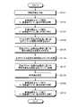
図18に示すように、まず取得部1102は視差画像を取得する(ステップS1101)。次に、データ生成部1103は、ステップS1101で取得された視差画像の各ラインに対して、ステップS1103~S1107の処理を繰り返し実行する(ステップS1102)。データ生成部1103は、所定の縦方向の間引き幅で、処理するラインを順番に選択していく。なお、図18のステップS1102の「画像縦幅分ループ開始」に付された括弧書きは(開始座標,終了座標,移動量)を示している。開始座標は任意であるため、図18の例では「*」で記載している。また、例えば視差画像を縦方向に領域分割して処理する場合には、領域ごとに設定した縦方向の間引き幅で画像アクセスを実行する。 As shown in FIG. 18, the
次に、データ生成部1103は、ステップS1102で指定したライン(横方向に延びるラインであって、縦方向の位置は任意のy)に対し、ステップS1104~ステップS1107の処理を繰り返し実行する(ステップS1103)。データ生成部1103は、所定の横方向の間引き幅で、処理する画素(アクセス画素)を順番に選択していく。なお、図18のステップS1103の「画像横幅分ループ開始」に付された括弧書きは(開始座標,終了座標,移動量)を示している。開始座標は任意であるため、図18の例では「*」で記載している。また、例えば視差画像を縦方向に領域分割して処理する場合には、領域ごとに設定した横方向の間引き幅で画像アクセスを実行する。 Next, the
以下、ステップS1104~ステップS1107の処理について説明する。ステップS1104において、データ生成部1103は、着目したアクセス画素(選択したアクセス画素)が有効であるか否かを判定する。Uマップを生成する場合は、推定路面よりも高い視差値を有する画素のみを投票するので、ここでは、データ生成部1103は、アクセス画素の視差値が、路面よりも高く、かつ、適正範囲内であることを示す範囲に収まっているか否かを判定することで、アクセス画素の有効無効を判定することができる。なお、Vマップでは、前記判定における路面からの高さ判定は不要であるため、視差値が適正範囲内であるか否かのみを判定してもよい。 The processing of steps S1104 to S1107 will be described below. In step S1104, the
上記判定の結果、アクセス画素が有効である場合は(ステップS1104:Yes)、処理はステップS1105に移行し、アクセス画素が無効である場合は(ステップS1104:No)、処理はステップS1108に移行する。 As a result of the above determination, if the access pixel is valid (step S1104: Yes), the process proceeds to step S1105, and if the access pixel is invalid (step S1104: No), the process proceeds to step S1108. .
ステップS1105において、データ生成部1103のパラメータ設定部11032(間引き幅設定部110321及び投票方式設定部110322)は、着目アクセス画素(有効と判定されたアクセス画素)の画素値(視差値)に基づき間引き幅及び投票方式を設定する。次に、ステップS1106において、投票部11033は、着目アクセス画素の画素値をUマップに投票する。 In step S1105, the parameter setting unit 11032 (thinning
次に、ステップS1107が実行されるが、図18の例では、投票方式として仮想投票方式が設定された場合の例を示す。ステップS1107において、投票部11033は、着目アクセス画素の画素値に基づき間引き画素の画素値をUマップに投票する。すなわち、着目アクセス画素の画素値を間引き画素の画素値と仮定してUマップに投票する。このステップS1107は、全画素投票方式が設定された場合及び単純間引き方式が設定された場合には実行されない。仮想投票方式の場合、上述したとおり、投票は縦方向、横方向、斜め方向の任意の方向に対して実行可能である。このとき、いずれか一つの方向のみに対して実行してもよいし、複数の方向に対して実行してもよい。 Next, step S1107 is executed, and the example in FIG. 18 shows an example in which the virtual voting method is set as the voting method. In step S1107, the
ステップS1108において、データ生成部1103は、ライン内に処理すべきアクセス画素が残存する場合は、ステップS1103以降の処理を繰り返す。ライン内に処理すべきアクセス画素が残存していない場合は、次のラインに進むため、処理はステップS1108に移行する。 In step S1108, the
ステップS1109において、データ生成部1103は、1ライン分の処理が完了した後、視差画像中に処理すべきラインが残存する場合は、ステップS1102以降の処理を繰り返す。視差画像中に処理すべきラインが残存していない場合は、処理を終了する。 In step S1109, when the line to be processed remains in the parallax image after the processing for one line is completed, the
以上に説明したように、本実施形態では、着目アクセス画素の画素値(距離情報)に基づいて、間引き幅、投票方式等のアクセス数パラメータが動的に調整される。これにより、処理速度と検知精度とのトレードオフを制御することが可能となる。 As described above, in the present embodiment, access count parameters such as the thinning width and voting method are dynamically adjusted based on the pixel value (distance information) of the target access pixel. This makes it possible to control the trade-off between processing speed and detection accuracy.
以下に他の実施形態について図面を参照して説明するが、第1の実施形態と共通の部分については同一の符号を付してその説明を省略する場合がある。 Other embodiments will be described below with reference to the drawings, but parts common to those of the first embodiment may be denoted by the same reference numerals, and descriptions thereof may be omitted.
(第2の実施形態)
次に、第2の実施形態について説明する。本実施形態は、着目アクセス画素が無効である場合に、着目アクセス画素の周辺に存在するアクセス済み画素の画素値(距離情報、視差値)に基づいて着目アクセス画素の画素値を補正する手段を有する点で、第1の実施形態と相違する。(Second embodiment)
Next, a second embodiment will be described. In this embodiment, when the access pixel of interest is invalid, the pixel value of the access pixel of interest is corrected based on the pixel values (distance information, parallax value) of the accessed pixels existing around the access pixel of interest. It differs from the first embodiment in that it has
図19は、第2の実施形態に係るデータ生成部2103の機能構成の一例を示す図である。本実施形態に係るデータ生成部2103は、アクセス部11031と、パラメータ設定部11032と、投票部11033と、画素値記憶部21034と、着目画素補正部21035とを有する。アクセス部11031とパラメータ設定部11032と投票部11033とは、第1の実施形態と同様の機能を有する。 FIG. 19 is a diagram showing an example of the functional configuration of the
画素値記憶部21034は、アクセス部11031が画素にアクセスすることにより取得した視差値を記憶する。本実施形態では、アクセス部11031によりアクセスされ視差値が取得された画素をアクセス済み画素と称する。画素値記憶部21034は、半導体メモリ等の適宜な記憶装置を利用して構成される。 The pixel
着目画素補正部21035は、着目アクセス画素が無効である場合に、当該着目アクセス画素の周辺に存在するアクセス済み画素の視差値に基づいて、当該着目アクセス画素の視差値を補正する。着目アクセス画素の有効無効の判定方法は特に限定されるものではないが、例えば第1の実施形態において例示したように、有効視差範囲を予め定義しておき、着目アクセス画素の視差値が有効視差範囲外である場合には、着目アクセス画素を無効と判定する方法等を採用してもよい。また、着目アクセス画素が有効である場合であっても、当該着目アクセス画素の視差値の信頼度を向上させるために、アクセス済み画素の視差値に基づいて当該着目アクセス画素の視差値を補正してもよい。着目画素補正部21035は、CPU31がプログラムを実行することにより実現されるが、これに限らず、例えば専用のハードウェア回路(例えばFPGA32等)で実現されてもよい。 When the access pixel of interest is invalid, the pixel-of-
図20は、着目アクセス画素の視差値の補正方法を説明するための視差画像の例を示す図である。図20には、無効と判定された着目アクセス画素γと、着目アクセス画素の走査方向下流側に位置する間引き画素δと、着目アクセス画素γから所定範囲内に存在するアクセス済み画素εとが示されている。着目アクセス画素γの視差値は、アクセス済み画素εの視差値に基づいて補正される。なお、着目アクセス画素γが有効である場合であっても、当該着目アクセス画素γの視差値の信頼度を向上させるために、アクセス済み画素の視差値に基づいて当該着目アクセス画素γの視差値を補正してもよい。そして、投票方式として仮想投票方式が設定された場合には、補正された着目アクセス画素γの視差値が間引き画素δの視差値としてディスパリティマップに投票される。 FIG. 20 is a diagram showing an example of a parallax image for explaining the method of correcting the parallax value of the access pixel of interest. FIG. 20 shows an access pixel of interest γ determined to be invalid, a thinned-out pixel δ located downstream of the access pixel of interest in the scanning direction, and an accessed pixel ε existing within a predetermined range from the access pixel of interest γ. It is The parallax value of the accessed pixel of interest γ is corrected based on the parallax value of the accessed pixel ε. Note that even when the access pixel γ of interest is valid, the parallax value of the access pixel γ of interest is calculated based on the disparity values of the accessed pixels in order to improve the reliability of the disparity value of the access pixel γ of interest. may be corrected. Then, when the virtual voting method is set as the voting method, the corrected parallax value of the target access pixel γ is voted in the disparity map as the parallax value of the thinned pixel δ.
例えば、視差画像を構成する各画素へのアクセス順序を、左上を原点とし、ライン内を左から右方向、ライン間を上から下方向とした場合、着目アクセス画素γの上側及び左側には、既にアクセスされ視差値が取得されたアクセス済み画素εが存在することとなる。アクセス済み画素εの視差値は、画素値記憶部21034に記憶される。そして、着目アクセス画素γが無効であった場合、又は有効であっても信頼度を向上させたい場合には、画素値記憶部21034に記憶されたアクセス済み画素εの視差値を用いて、着目アクセス画素γの視差値となる補正値を算出する。 For example, when the order of access to each pixel constituting the parallax image is set such that the top left is the origin, the line is from left to right, and the space between lines is from top to bottom, above and to the left of the target access pixel γ are: There will be accessed pixels ε that have already been accessed and for which disparity values have been obtained. A parallax value of the accessed pixel ε is stored in the pixel
補正値の算出方法は特に限定されるものではないが、補正値は、例えば、アクセス済み画素εの1以上の視差値の平均値、重み付き平均値、中央値、最大値、最小値、最頻値等であり得る。また、アクセス済み画素εが無効である場合には、当該無効であるアクセス済み画素εの視差値を無視してもよい。 The method of calculating the correction value is not particularly limited. It can be frequent values and the like. Also, when the accessed pixel ε is invalid, the parallax value of the invalid accessed pixel ε may be ignored.
上記のように、補正値は、着目アクセス画素γから所定範囲内に存在するアクセス済み画素εの視差値に基づいて算出されるが、当該所定範囲は、使用条件に応じて適宜設定されるべきものである。所定範囲を広く設定すると、補正値を算出するために参照されるアクセス済み画素εが多くなり、補正値の精度を向上させることが可能となるが、画素値記憶部21034の記憶容量の増大化や処理速度の低下等を招く場合がある。一方、所定範囲を狭く設定すると、補正値を算出するために参照されるアクセス済み画素εが少なくなり、画素値記憶部21034の記憶容量の縮小化や処理速度の向上等を図ることができるが、補正値の精度の低下を招く場合がある。従って、記憶容量や処理速度の問題と補正値の精度の問題とはトレードオフの関係にあり、上記所定範囲は所望するトレードオフに基づいて設定すればよい。 As described above, the correction value is calculated based on the parallax value of the accessed pixel ε existing within a predetermined range from the target access pixel γ. It is. If the predetermined range is set wide, the number of accessed pixels ε to be referenced for calculating the correction value increases, and the accuracy of the correction value can be improved, but the storage capacity of the pixel
間引き幅が大きい場合、アクセス画素の数が減少する。このような状況下で着目アクセス画素γにミスヒット(例えば、有効視差範囲外の視差値の取得等)が生じると、路面や物体の検知精度が低下する。ミスヒットによる問題は、特に、遠方検知時、夜間、雨天、水たまり、逆光等の検知困難状況下において発生しやすい。そこで、上記のように着目アクセス画素γの視差値をアクセス済み画素εの視差値に基づいて補正することにより、間引き幅が大きい場合や検知困難状況下においても、検知精度を向上させることが可能となる。なお、上記のような補正処理を実行するか否かを、所定の条件に基づいて決定してもよい。例えば、視差画像を所定サイズの複数の領域(例えば上方領域及び下方領域等)に分割し、領域毎に補正処理を実行するか否かを決定してもよい。 If the thinning width is large, the number of accessed pixels is reduced. Under such circumstances, if a miss-hit occurs in the target access pixel γ (for example, acquisition of a parallax value outside the effective parallax range), the detection accuracy of the road surface and the object deteriorates. Problems caused by miss-hit are particularly likely to occur when sensing from a distance, at night, in rainy weather, in puddles, in backlight, or other conditions that make detection difficult. Therefore, by correcting the parallax value of the accessed pixel γ of interest based on the parallax value of the accessed pixel ε as described above, it is possible to improve the detection accuracy even when the thinning width is large or when detection is difficult. becomes. It should be noted that whether or not to execute the correction process as described above may be determined based on a predetermined condition. For example, the parallax image may be divided into a plurality of regions of a predetermined size (for example, an upper region and a lower region), and whether or not to perform correction processing may be determined for each region.
図21は、第2の実施形態におけるUマップ生成部105の動作例を示すフローチャートである。なお、ここではUマップ生成部105の動作例を説明するが、Vマップ生成部103の動作例についても同様に考えることができる。 FIG. 21 is a flow chart showing an operation example of the
図21に示すように、まず取得部1102は視差画像を取得する(ステップS2101)。次に、データ生成部1103は、ステップS2101で取得された視差画像の各ラインに対して、ステップS2103~S2108の処理を繰り返し実行する(ステップS2102)。データ生成部2103は、所定の縦方向の間引き幅で、処理するラインを順番に選択していく。なお、図21のステップS2102の「画像縦幅分ループ開始」に付された括弧書きは(開始座標,終了座標,移動量)を示している。開始座標は任意であるため、図21の例では「*」で記載している。また、例えば視差画像を縦方向に領域分割して処理する場合には、領域ごとに設定した縦方向の間引き幅で画像アクセスを実行する。 As shown in FIG. 21, the
次に、データ生成部2103は、ステップS2102で指定したライン(横方向に延びるラインであって、縦方向の位置は任意のy)に対し、ステップS2104~ステップS2108の処理を繰り返し実行する(ステップS2103)。データ生成部2103は、所定の横方向の間引き幅で、処理する画素(アクセス画素)を順番に選択していく。なお、図21のステップS2103の「画像横幅分ループ開始」に付された括弧書きは(開始座標,終了座標,移動量)を示している。開始座標は任意であるため、図21の例では「*」で記載している。また、例えば視差画像を縦方向に領域分割して処理する場合には、領域ごとに設定した横方向の間引き幅で画像アクセスを実行する。 Next, the
以下、ステップS2104~ステップS2108の処理について説明する。ステップS2104において、データ生成部2103は、アクセス済み画素の画素値(視差値)に基づいて着目アクセス画素の画素値を補正する。当該画素値の補正は、無効な着目アクセス画素についてのみ行われてもよいし、有効な着目アクセス画素の信頼度を向上させるために行われてもよい。 The processing of steps S2104 to S2108 will be described below. In step S2104, the
ステップS2105において、データ生成部2103のパラメータ設定部11032(間引き幅設定部110321及び投票方式設定部110322)は、補正された着目アクセス画素の画素値に基づき間引き幅及び投票方式を設定する。次に、ステップS2106において、投票部11033は、補正された着目アクセス画素の画素値をUマップに投票する。 In step S2105, the parameter setting unit 11032 (thinning
次に、ステップS2107が実行されるが、図21の例では、投票方式として仮想投票方式が設定された場合の例を示す。ステップS2107において、投票部11033は、補正された着目アクセス画素の画素値に基づき間引き画素の画素値をUマップに投票する。すなわち、補正された着目アクセス画素の画素値を間引き画素の画素値と仮定してUマップに投票する。このステップS2107は、全画素投票方式が設定された場合及び単純間引き方式が設定された場合には実行されない。仮想投票方式の場合、上述したとおり、投票は縦方向、横方向、斜め方向の任意の方向に対して実行可能である。このとき、いずれか一つの方向のみに対して実行してもよいし、複数の方向に対して実行してもよい。 Next, step S2107 is executed, and the example in FIG. 21 shows an example in which the virtual voting method is set as the voting method. In step S2107, the
次に、ステップS2108において、着目アクセス画素の画素値(補正された画素値を含む)を画素値記憶部214034に記憶させる。 Next, in step S2108, the pixel value of the target access pixel (including the corrected pixel value) is stored in the pixel value storage unit 214034. FIG.
ステップS2109において、データ生成部2103は、ライン内に処理すべきアクセス画素が残存する場合は、ステップS2103以降の処理を繰り返す。ライン内に処理すべきアクセス画素が残存していない場合は、次のラインに進むため、処理はステップS2110に移行する。 In step S2109, the
ステップS2110において、データ生成部2103は、1ライン分の処理が完了した後、視差画像中に処理すべきラインが残存する場合は、ステップS2102以降の処理を繰り返す。視差画像中に処理すべきラインが残存していない場合は、処理を終了する。 In step S2110, when the line to be processed remains in the parallax image after the processing for one line is completed, the
以上に説明したように、本実施形態では、着目アクセス画素の画素値(距離情報)に基づいて、間引き幅、投票方式等のアクセス数パラメータが動的に調整されると共に、着目アクセス画素の画素値がアクセス済み画素の画素値に基づいて補正される。これにより、着目アクセス画素の画素値が無効値であっても有効な画素値に補正できるため、処理速度と検知精度とのトレードオフを制御することが可能となると共に、検知精度の向上を図ることが可能となる。 As described above, in the present embodiment, based on the pixel value (distance information) of the access pixel of interest, access number parameters such as the thinning width and voting method are dynamically adjusted, and the pixel of the access pixel of interest is The value is corrected based on the pixel value of the accessed pixel. As a result, even if the pixel value of the target access pixel is an invalid value, it can be corrected to a valid pixel value, so that it is possible to control the trade-off between the processing speed and the detection accuracy, and to improve the detection accuracy. becomes possible.
以上、本発明の実施形態を説明したが、上記実施形態は例として提示したものであり、発明の範囲を限定することを意図するものではない。この新規な実施形態はその他の様々な形態で実施されることが可能であり、発明の要旨を逸脱しない範囲で種々の省略、置き換え、変更を行うことができる。この実施形態及びその変形は発明の範囲及び要旨に含まれるとともに、特許請求の範囲に記載された発明とその均等の範囲に含まれる。 Although the embodiment of the present invention has been described above, the above embodiment is presented as an example and is not intended to limit the scope of the invention. This novel embodiment can be embodied in various other forms, and various omissions, replacements, and modifications can be made without departing from the scope of the invention. This embodiment and its modifications are included in the scope and gist of the invention, and are included in the scope of the invention described in the claims and its equivalents.
また、上述した実施形態の機器制御システム1で実行されるプログラムは、インストール可能な形式または実行可能な形式のファイルでCD-ROM、フレキシブルディスク(FD)、CD-R、DVD(Digital Versatile Disk)、USB(Universal Serial Bus)等のコンピュータで読み取り可能な記録媒体に記録して提供するように構成してもよいし、インターネット等のネットワーク経由で提供または配布するように構成してもよい。また、各種プログラムを、ROM等に予め組み込んで提供するように構成してもよい。 Further, the program executed by the
1 機器制御システム
10 車両
11 撮像ユニット
12 ステレオカメラ
13 画像解析ユニット
15 左側視界
16 右側視界
21a 第1のカメラ部
21b 第2のカメラ部
22 レンズ
23 画像センサ
24 センサコントローラ
31 CPU
32 FPGA
33 ROM
34 RAM
35 シリアルIF
36 データIF
42 シリアルバスライン
51 車両ECU
101 撮像部
102 視差計算部
103 Vマップ生成部
104 路面推定部
105 Uマップ生成部
106 クラスタリング部
107 棄却部
108 トラッキング部
109 制御部
1101 ネットワークバス
1102 取得部
1103,2103 データ生成部
11031 アクセス部
11032 パラメータ設定部
11033 投票部
21034 画素値記憶部
21035 着目画素補正部
110321 間引き幅設定部
110322 投票方式設定部1
32 FPGAs
33 ROMs
34 RAMs
35 serial interface
36 data interface
42
101 imaging unit 102 parallax calculation unit 103 V
Claims (12)
Translated fromJapanese前記取得部により取得された前記視差画像の前記画素にアクセスすることにより取得した前記距離情報に基づいてデータを生成するデータ生成部と、
を備え、
前記データ生成部は、前記視差画像に基づいて取得した前記距離情報が示す距離が遠いほど前記画素へのアクセス数が増加するように、且つ前記距離が近いほど前記アクセス数が減少するように、前記アクセス数を変化させるパラメータを設定する、
情報処理装置。an acquisition unit that acquires a parallax image having distance information for each pixel;
a data generating unit that generates data based on the distance information obtained by accessing the pixels of the parallax image obtained by the obtaining unit;
with
The data generation unit increases the number of accesses to the pixels as the distance indicated by the distance information acquired based on the parallax image increases, and decreases the number of accesses as the distance decreases. setting a parameter that changes the number of accesses;
Information processing equipment.
請求項1に記載の情報処理装置。The data generated by the data generation unit is a V map indicating the relationship between the vertical position of theparallax image and the distance, or the relationship between the horizontal position of theparallax image and the distance exceeding the height from the road surface. is a U map showing
The information processing device according to claim 1 .
前記パラメータは、間引かれる画素の数を示す間引き幅である、
請求項1又は2に記載の情報処理装置。The data generation unit thins out and accesses one or more pixels among a plurality of pixels included in theparallax image,
the parameter is a decimation width indicating the number of pixels to be decimated;
The information processing apparatus according to claim 1 or 2.
前記パラメータは、前記距離情報の投票方法を示す投票方式である、
請求項1~3のいずれか1項に記載の情報処理装置。The data generation unit generates the data by voting the acquired distance information on a map,
The parameter is a voting method indicating a voting method for the distance information,
The information processing apparatus according to any one of claims 1 to 3.
請求項4に記載の情報処理装置。The voting method is an all-pixel voting method in which the distance information obtained from all pixels is voted, a simple thinning method in which only the distance information obtained from the accessed pixels is voted, or a distance information obtained from the accessed pixels is accessed. is a virtual voting method that votes as distance information for unaccessed pixels that are not
The information processing apparatus according to claim 4.
請求項1~5のいずれか1項に記載の情報処理装置。The data generation unit determines whether the distance information of the pixel is valid, and sets the parameter based on the valid distance information.
The information processing apparatus according to any one of claims 1 to 5.
請求項1~6のいずれか1項に記載の情報処理装置。The data generation unit corrects the distance information of the pixel of interest based on the distance information of the accessed pixels existing within a predetermined range from the pixel of interest.
The information processing apparatus according to any one of claims 1 to 6.
請求項7に記載の情報処理装置。The data generator calculates the distance of the target pixel based on one of an average value, a weighted average value, a maximum value, a minimum value, a median value, and a mode value of the distance information of the accessed pixels. correct the information,
The information processing apparatus according to claim 7.
前記情報処理装置による情報処理の結果に基づく制御を行う制御装置と、を備える、
システム。The information processing device according to any one of claims 1 to 8,
A control device that performs control based on the result of information processing by the information processing device,
system.
前記情報処理装置による情報処理の結果に基づく制御を行う制御装置と、を備える、
移動体。The information processing device according to any one of claims 1 to 8,
A control device that performs control based on the result of information processing by the information processing device,
Mobile.
前記取得された前記視差画像の前記画素にアクセスすることにより取得した前記距離情報に基づいてデータを生成するステップと、
前記視差画像に基づいて取得した前記距離情報が示す距離が遠いほど前記画素へのアクセス数が増加するように、且つ前記距離が近いほど前記アクセス数が減少するように、前記アクセス数を変化させるパラメータを設定するステップと、
を含む情報処理方法。obtaining a parallax image having distance information for each pixel;
generatingdata based on the distance information obtained by accessing the pixels of the obtained parallax image;
The number of accesses is changed such that the number of accesses to the pixels increases as the distance indicated by the distance information acquired based on the parallax image increases, and the number of accesses decreases as the distance decreases. setting parameters;
Information processing method including.
画素毎に距離情報を有する視差画像を取得する処理と、
前記取得された前記視差画像の前記画素にアクセスすることにより取得した前記距離情報に基づいてデータを生成する処理と、
前記視差画像に基づいて取得した前記距離情報が示す距離が遠いほど前記画素へのアクセス数が増加するように、且つ前記距離が近いほど前記アクセス数が減少するように、前記アクセス数を変化させるパラメータを設定する処理と、
を実行させるプログラム。to the computer,
A process of acquiring a parallax image having distance information for each pixel;
a process of generating data based on the distance information obtained by accessing the pixels of the obtained parallax image;
The number of accesses is changed such that the number of accesses to the pixels increases as the distance indicated by the distance information acquired based on the parallax image increases, and the number of accesses decreases as the distance decreases. a process of setting parameters;
program to run.
Priority Applications (2)
| Application Number | Priority Date | Filing Date | Title |
|---|---|---|---|
| JP2018147868AJP7187875B2 (en) | 2018-08-06 | 2018-08-06 | Information processing device, system, moving object, information processing method and program |
| EP19188257.0AEP3608832A1 (en) | 2018-08-06 | 2019-07-25 | Image display apparatus, image display method, and carrier means |
Applications Claiming Priority (1)
| Application Number | Priority Date | Filing Date | Title |
|---|---|---|---|
| JP2018147868AJP7187875B2 (en) | 2018-08-06 | 2018-08-06 | Information processing device, system, moving object, information processing method and program |
Publications (2)
| Publication Number | Publication Date |
|---|---|
| JP2020024114A JP2020024114A (en) | 2020-02-13 |
| JP7187875B2true JP7187875B2 (en) | 2022-12-13 |
Family
ID=67438837
Family Applications (1)
| Application Number | Title | Priority Date | Filing Date |
|---|---|---|---|
| JP2018147868AActiveJP7187875B2 (en) | 2018-08-06 | 2018-08-06 | Information processing device, system, moving object, information processing method and program |
Country Status (2)
| Country | Link |
|---|---|
| EP (1) | EP3608832A1 (en) |
| JP (1) | JP7187875B2 (en) |
Citations (3)
| Publication number | Priority date | Publication date | Assignee | Title |
|---|---|---|---|---|
| WO2015059970A1 (en) | 2013-10-23 | 2015-04-30 | オリンパス株式会社 | Imaging device and phase difference detection method |
| JP2018045680A (en) | 2016-09-12 | 2018-03-22 | 株式会社リコー | Image processing apparatus, object recognition apparatus, device control system, moving object, image processing method and program |
| JP2018088234A (en) | 2016-11-22 | 2018-06-07 | 株式会社リコー | Information processing apparatus, imaging apparatus, device control system, moving object, information processing method, and program |
Family Cites Families (4)
| Publication number | Priority date | Publication date | Assignee | Title |
|---|---|---|---|---|
| CN105335955B (en)* | 2014-07-17 | 2018-04-10 | 株式会社理光 | Method for checking object and object test equipment |
| EP3115933B1 (en)* | 2015-07-07 | 2021-03-17 | Ricoh Company, Ltd. | Image processing device, image capturing device, mobile body control system, image processing method, and computer-readable recording medium |
| JP6657789B2 (en) | 2015-10-29 | 2020-03-04 | 株式会社リコー | Image processing device, imaging device, device control system, frequency distribution image generation method, and program |
| JP6950170B2 (en)* | 2016-11-30 | 2021-10-13 | 株式会社リコー | Information processing device, imaging device, device control system, information processing method, and program |
- 2018
- 2018-08-06JPJP2018147868Apatent/JP7187875B2/enactiveActive
- 2019
- 2019-07-25EPEP19188257.0Apatent/EP3608832A1/enactivePending
Patent Citations (3)
| Publication number | Priority date | Publication date | Assignee | Title |
|---|---|---|---|---|
| WO2015059970A1 (en) | 2013-10-23 | 2015-04-30 | オリンパス株式会社 | Imaging device and phase difference detection method |
| JP2018045680A (en) | 2016-09-12 | 2018-03-22 | 株式会社リコー | Image processing apparatus, object recognition apparatus, device control system, moving object, image processing method and program |
| JP2018088234A (en) | 2016-11-22 | 2018-06-07 | 株式会社リコー | Information processing apparatus, imaging apparatus, device control system, moving object, information processing method, and program |
Also Published As
| Publication number | Publication date |
|---|---|
| JP2020024114A (en) | 2020-02-13 |
| EP3608832A1 (en) | 2020-02-12 |
Similar Documents
| Publication | Publication Date | Title |
|---|---|---|
| CN111971682B (en) | Road surface detection device, image display device, obstacle detection device, road surface detection method, image display method, and obstacle detection method | |
| JP6023216B2 (en) | In-vehicle image processing device | |
| JP6303090B2 (en) | Image processing apparatus and image processing program | |
| JP4987573B2 (en) | Outside monitoring device | |
| KR102772870B1 (en) | Electronic device and control method | |
| JP7206583B2 (en) | Information processing device, imaging device, device control system, moving object, information processing method and program | |
| JP2013190421A (en) | Method for improving detection of traffic-object position in vehicle | |
| JP2011128756A (en) | Object detection device | |
| JP2012073927A (en) | Driving support apparatus | |
| JP2013164351A (en) | Stereo parallax calculation device | |
| JP2018060422A (en) | Object detection device | |
| JP6907513B2 (en) | Information processing equipment, imaging equipment, equipment control system, information processing method and program | |
| JP2011175572A (en) | Lane recognition device | |
| EP3545465A1 (en) | Information processing apparatus, imaging apparatus, apparatus control system, movable object, information processing method, and information processing program | |
| US12371068B2 (en) | Electronic instrument, movable apparatus, distance calculation method, and storage medium | |
| JP2021113767A (en) | Obstacle detection device and obstacle detection system | |
| JP7187875B2 (en) | Information processing device, system, moving object, information processing method and program | |
| JP2019160251A (en) | Image processing device, object recognition device, instrument control system, moving body, image processing method and program | |
| JP2018088217A (en) | Information processing device, imaging device, apparatus control system, information processing method, and program | |
| JP7322576B2 (en) | Information processing device, imaging device, and moving object | |
| JP4788399B2 (en) | Pedestrian detection method, apparatus, and program | |
| JP7052265B2 (en) | Information processing device, image pickup device, device control system, mobile body, information processing method, and information processing program | |
| JP2013206328A (en) | Object detection device | |
| WO2022113470A1 (en) | Image processing device and image processing method | |
| JP6429101B2 (en) | Image determination apparatus, image processing apparatus, image determination program, image determination method, moving object |
Legal Events
| Date | Code | Title | Description |
|---|---|---|---|
| A621 | Written request for application examination | Free format text:JAPANESE INTERMEDIATE CODE: A621 Effective date:20210616 | |
| RD04 | Notification of resignation of power of attorney | Free format text:JAPANESE INTERMEDIATE CODE: A7424 Effective date:20220204 | |
| A977 | Report on retrieval | Free format text:JAPANESE INTERMEDIATE CODE: A971007 Effective date:20220413 | |
| A131 | Notification of reasons for refusal | Free format text:JAPANESE INTERMEDIATE CODE: A131 Effective date:20220426 | |
| A521 | Request for written amendment filed | Free format text:JAPANESE INTERMEDIATE CODE: A523 Effective date:20220608 | |
| A131 | Notification of reasons for refusal | Free format text:JAPANESE INTERMEDIATE CODE: A131 Effective date:20220712 | |
| A521 | Request for written amendment filed | Free format text:JAPANESE INTERMEDIATE CODE: A523 Effective date:20220906 | |
| TRDD | Decision of grant or rejection written | ||
| A01 | Written decision to grant a patent or to grant a registration (utility model) | Free format text:JAPANESE INTERMEDIATE CODE: A01 Effective date:20221101 | |
| A61 | First payment of annual fees (during grant procedure) | Free format text:JAPANESE INTERMEDIATE CODE: A61 Effective date:20221114 | |
| R151 | Written notification of patent or utility model registration | Ref document number:7187875 Country of ref document:JP Free format text:JAPANESE INTERMEDIATE CODE: R151 |