JP7187450B2 - patient interface - Google Patents
patient interfaceDownload PDFInfo
- Publication number
- JP7187450B2 JP7187450B2JP2019518447AJP2019518447AJP7187450B2JP 7187450 B2JP7187450 B2JP 7187450B2JP 2019518447 AJP2019518447 AJP 2019518447AJP 2019518447 AJP2019518447 AJP 2019518447AJP 7187450 B2JP7187450 B2JP 7187450B2
- Authority
- JP
- Japan
- Prior art keywords
- frame
- mask
- configurations
- nose
- headgear
- Prior art date
- Legal status (The legal status is an assumption and is not a legal conclusion. Google has not performed a legal analysis and makes no representation as to the accuracy of the status listed.)
- Active
Links
Images


Classifications
- A—HUMAN NECESSITIES
- A61—MEDICAL OR VETERINARY SCIENCE; HYGIENE
- A61M—DEVICES FOR INTRODUCING MEDIA INTO, OR ONTO, THE BODY; DEVICES FOR TRANSDUCING BODY MEDIA OR FOR TAKING MEDIA FROM THE BODY; DEVICES FOR PRODUCING OR ENDING SLEEP OR STUPOR
- A61M16/00—Devices for influencing the respiratory system of patients by gas treatment, e.g. ventilators; Tracheal tubes
- A61M16/06—Respiratory or anaesthetic masks
- A61M16/0605—Means for improving the adaptation of the mask to the patient
- A61M16/0616—Means for improving the adaptation of the mask to the patient with face sealing means comprising a flap or membrane projecting inwards, such that sealing increases with increasing inhalation gas pressure
- A—HUMAN NECESSITIES
- A61—MEDICAL OR VETERINARY SCIENCE; HYGIENE
- A61M—DEVICES FOR INTRODUCING MEDIA INTO, OR ONTO, THE BODY; DEVICES FOR TRANSDUCING BODY MEDIA OR FOR TAKING MEDIA FROM THE BODY; DEVICES FOR PRODUCING OR ENDING SLEEP OR STUPOR
- A61M16/00—Devices for influencing the respiratory system of patients by gas treatment, e.g. ventilators; Tracheal tubes
- A61M16/06—Respiratory or anaesthetic masks
- A61M16/0605—Means for improving the adaptation of the mask to the patient
- A61M16/0611—Means for improving the adaptation of the mask to the patient with a gusset portion
- A—HUMAN NECESSITIES
- A61—MEDICAL OR VETERINARY SCIENCE; HYGIENE
- A61M—DEVICES FOR INTRODUCING MEDIA INTO, OR ONTO, THE BODY; DEVICES FOR TRANSDUCING BODY MEDIA OR FOR TAKING MEDIA FROM THE BODY; DEVICES FOR PRODUCING OR ENDING SLEEP OR STUPOR
- A61M16/00—Devices for influencing the respiratory system of patients by gas treatment, e.g. ventilators; Tracheal tubes
- A61M16/06—Respiratory or anaesthetic masks
- A61M16/0683—Holding devices therefor
- A—HUMAN NECESSITIES
- A61—MEDICAL OR VETERINARY SCIENCE; HYGIENE
- A61M—DEVICES FOR INTRODUCING MEDIA INTO, OR ONTO, THE BODY; DEVICES FOR TRANSDUCING BODY MEDIA OR FOR TAKING MEDIA FROM THE BODY; DEVICES FOR PRODUCING OR ENDING SLEEP OR STUPOR
- A61M16/00—Devices for influencing the respiratory system of patients by gas treatment, e.g. ventilators; Tracheal tubes
- A61M16/08—Bellows; Connecting tubes ; Water traps; Patient circuits
- A61M16/0816—Joints or connectors
- A—HUMAN NECESSITIES
- A61—MEDICAL OR VETERINARY SCIENCE; HYGIENE
- A61M—DEVICES FOR INTRODUCING MEDIA INTO, OR ONTO, THE BODY; DEVICES FOR TRANSDUCING BODY MEDIA OR FOR TAKING MEDIA FROM THE BODY; DEVICES FOR PRODUCING OR ENDING SLEEP OR STUPOR
- A61M16/00—Devices for influencing the respiratory system of patients by gas treatment, e.g. ventilators; Tracheal tubes
- A61M16/20—Valves specially adapted to medical respiratory devices
- A61M16/208—Non-controlled one-way valves, e.g. exhalation, check, pop-off non-rebreathing valves
- A—HUMAN NECESSITIES
- A61—MEDICAL OR VETERINARY SCIENCE; HYGIENE
- A61M—DEVICES FOR INTRODUCING MEDIA INTO, OR ONTO, THE BODY; DEVICES FOR TRANSDUCING BODY MEDIA OR FOR TAKING MEDIA FROM THE BODY; DEVICES FOR PRODUCING OR ENDING SLEEP OR STUPOR
- A61M2210/00—Anatomical parts of the body
- A61M2210/06—Head
- A61M2210/0618—Nose
- A—HUMAN NECESSITIES
- A61—MEDICAL OR VETERINARY SCIENCE; HYGIENE
- A61M—DEVICES FOR INTRODUCING MEDIA INTO, OR ONTO, THE BODY; DEVICES FOR TRANSDUCING BODY MEDIA OR FOR TAKING MEDIA FROM THE BODY; DEVICES FOR PRODUCING OR ENDING SLEEP OR STUPOR
- A61M2210/00—Anatomical parts of the body
- A61M2210/06—Head
- A61M2210/0625—Mouth
Landscapes
- Health & Medical Sciences (AREA)
- Pulmonology (AREA)
- Life Sciences & Earth Sciences (AREA)
- Animal Behavior & Ethology (AREA)
- Anesthesiology (AREA)
- Biomedical Technology (AREA)
- Heart & Thoracic Surgery (AREA)
- Hematology (AREA)
- Emergency Medicine (AREA)
- Engineering & Computer Science (AREA)
- General Health & Medical Sciences (AREA)
- Public Health (AREA)
- Veterinary Medicine (AREA)
- Respiratory Apparatuses And Protective Means (AREA)
- Percussion Or Vibration Massage (AREA)
- Pharmaceuticals Containing Other Organic And Inorganic Compounds (AREA)
- Ultra Sonic Daignosis Equipment (AREA)
Description
Translated fromJapanese関連出願の相互参照
本出願は、2016年10月5日出願の米国仮特許出願第62/413,604号明細書、2017年10月26日出願の米国仮特許出願第62/413,280号明細書および2016年10月27日出願の米国仮特許出願第62/404,341号明細書に対する優先権を主張し、これらのそれぞれの全体が参照により本書に援用される。CROSS-REFERENCE TO RELATED APPLICATIONS This application is filed October 5, 2016, U.S. Provisional Application No. 62/413,604, and U.S. Provisional Application No. 62/413,280, filed October 26, 2017. This specification and priority to US Provisional Patent Application No. 62/404,341 filed October 27, 2016, each of which is hereby incorporated by reference in its entirety.
本開示は、呼吸療法のためのインターフェースアセンブリに関する。特に、本開示は、使用者の鼻の鼻梁を覆わない鼻下型(under-nose)のインターフェースアセンブリに関する。 The present disclosure relates to interface assemblies for respiratory therapy. In particular, the present disclosure relates to under-nose interface assemblies that do not cover the bridge of the user's nose.
閉塞性睡眠時無呼吸(OSA)を患う患者では、通常、上気道を開いた状態に保つ筋肉が、寝ている間、気道が圧迫されるかまたは完全に塞がれる程度に弛緩し、この現象が、いびきの形態で現れる。これがある期間にわたって生じると、患者の脳は、一般に、低酸素症の恐れを認識し、および気道を開かせるために、部分的に患者を覚醒させて、正常呼吸を再開させ得る。患者は、睡眠セッション当たり数百回も生じ得るこれらの覚醒エピソードに気付かないことがあり得る。この部分的な覚醒状態は、患者の睡眠の質を著しく低下させる可能性があり、時間が経つにつれて、日中の過剰な眠気、慢性疲労、高心拍数、血圧の上昇、体重増加、頭痛、被刺激性、鬱病および不安を含む、様々な症状を生じる可能性がある。 In patients with obstructive sleep apnea (OSA), the muscles that normally keep the upper airway open relax during sleep to the extent that the airway is compressed or completely blocked, causing this. The phenomenon manifests itself in the form of snoring. When this occurs over a period of time, the patient's brain generally recognizes the threat of hypoxia and may partially awaken the patient to resume normal breathing in order to open the airways. Patients may be unaware of these awakening episodes, which can occur hundreds of times per sleep session. This partial wakefulness can significantly reduce the patient's sleep quality and, over time, lead to excessive daytime sleepiness, chronic fatigue, high heart rate, elevated blood pressure, weight gain, headaches, A variety of symptoms can occur, including irritability, depression and anxiety.
閉塞性睡眠時無呼吸は、一般に、気道陽圧(PAP)療法を行うことによって治療される。PAP療法は、大気圧を上回る治療圧力で、患者にガス流を送出することを含み、この治療圧力は、無呼吸、呼吸低下および/または流れの制限の頻度および/または持続期間を減少させる。この療法は、気道陽圧装置を使用して、加圧気流を、導管を通って、患者の顔に位置決めされた患者用インターフェースまたはマスクによって患者まで送出することによって実施されることが多い。 Obstructive sleep apnea is commonly treated by administering positive airway pressure (PAP) therapy. PAP therapy involves delivering a flow of gas to a patient at a therapeutic pressure above atmospheric pressure that reduces the frequency and/or duration of apnea, hypopnea and/or flow limitation. This therapy is often performed by using a positive airway pressure device to deliver pressurized airflow through a conduit to the patient via a patient interface or mask positioned on the patient's face.
ガスの投与を含む、PAP療法または他の呼吸療法と一緒に使用される一般的なタイプの1つの患者用インターフェースアセンブリは、インターフェースアセンブリの使用者の鼻の鼻梁と接触するシールを含む。鼻の鼻梁は、インターフェースアセンブリのシールによって加えられる圧力に敏感である。最近になって、鼻の鼻梁に接触しないインターフェースアセンブリが入手できるようになってきている。そのようなインターフェースアセンブリは、「鼻下型」インターフェースアセンブリと呼ばれ得る。快適さおよび/または密封性が改善された改良型の鼻下型インターフェースアセンブリを提供するための、または有用な選択肢を公衆に提供するためのニーズが存在する。 One common type of patient interface assembly used with PAP therapy or other respiratory therapy, including administration of gas, includes a seal that contacts the bridge of the nose of the user of the interface assembly. The bridge of the nose is sensitive to pressure exerted by the interface assembly seals. More recently, interface assemblies have become available that do not contact the bridge of the nose. Such an interface assembly may be referred to as an "under-the-nose" interface assembly. A need exists to provide an improved under-the-nose interface assembly with improved comfort and/or sealing, or to provide the public with a useful choice.
本明細書で説明するシステム、方法および装置は、発明的な態様を有し、そのいずれの1つも不可欠ではなく、またはそれらの所望の特質について単独でその要因となるものでもない。特許請求の範囲を限定することなく、有利な特徴のいくつかを以下に要約する。 The systems, methods and apparatus described herein have inventive aspects, no one of which is essential or solely responsible for their desirable attributes. Without limiting the scope of the claims, some of the advantageous features are summarized below.
いくつかの構成では、陽圧呼吸療法を提供することにおいて使用するためのインターフェースは、マスクシールを有するマスクアセンブリを含む。マスクアセンブリは、使用者の顔の鼻の鼻梁よりも十分に低く位置決めされ、かつ使用者の鼻の露出された鼻梁を提供するように構成される。マスクシールは、少なくとも1つの鼻開口部を含む鼻領域を含む。マスクシールは、鼻領域の第1の側部における第1のパドルおよび鼻領域の第2の側部における第2のパドルを含む。第1のパドルは、使用者の鼻の一方の側面に接触するように構成され、および第2のパドルは、使用者の鼻の他方の側面に接触するように構成される。第1のパドルは、第1のパドルの前側から第1のパドルの後側まで延在する第1のカットアウト領域を含む。第2のパドルは、第2のパドルの前側から第2のパドルの後側まで延在する第2のカットアウト領域を含む。 In some configurations, an interface for use in providing positive airway pressure therapy includes a mask assembly having a mask seal. The mask assembly is positioned sufficiently below the nasal bridge of the user's face and is configured to provide an exposed nasal bridge of the user's nose. The mask seal includes a nasal region including at least one nasal opening. The mask seal includes a first paddle on a first side of the nasal region and a second paddle on a second side of the nasal region. A first paddle is configured to contact one side of the user's nose and a second paddle is configured to contact the other side of the user's nose. The first paddle includes a first cutout area extending from the front side of the first paddle to the rear side of the first paddle. The second paddle includes a second cutout area extending from the front side of the second paddle to the rear side of the second paddle.
いくつかの構成では、マスクシールは、マスクシールの鼻領域を支持するように構成された支持構造をさらに含む。 In some configurations, the mask seal further includes a support structure configured to support the nose region of the mask seal.
いくつかの構成では、マスクシールは、フレームパドルを受け入れるように構成された上部の窪んだ前面を含む窪んだ前面を含む。 In some configurations, the mask seal includes a recessed front surface including an upper recessed front surface configured to receive the frame paddle.
いくつかの構成では、第1のカットアウト領域は、低減された壁厚さを含む。 In some configurations, the first cutout region includes a reduced wall thickness.
いくつかの構成では、第1のカットアウト領域は、第1のカットアウト領域の長さに沿って位置決めされた第1の凹状部分を含み、および第2のカットアウト領域は、第2のカットアウト領域の長さに沿って位置決めされた第2の凹状部分を含む。 In some configurations, the first cutout area includes a first recessed portion positioned along the length of the first cutout area, and the second cutout area comprises a second cutout. A second recessed portion positioned along the length of the out region is included.
いくつかの構成では、第1の凹状部分は、第1のパドルに力が加えられるときに第1のカットアウト領域を内向きに折り畳むことができるように構成され、および第2の凹状部分は、第2のパドルに力が加えられるときに第2のカットアウト領域を内向きに折り畳むことができるように構成される。 In some configurations, the first recessed portion is configured to allow the first cutout region to fold inwardly when a force is applied to the first paddle, and the second recessed portion is , to allow the second cutout region to fold inwardly when a force is applied to the second paddle.
いくつかの構成では、マスクシールは、マスクシールの外周側に沿って位置決めされる凹面領域を含む。 In some configurations, the mask seal includes a concave area positioned along the outer peripheral side of the mask seal.
いくつかの構成では、第1のカットアウト領域は、第1の内側領域および第1の外側領域を含む。第1の内側領域は、第1の内側領域に力が加えられるときに第1の外側領域に向かって圧縮するように構成される。第2のカットアウト領域は、第2の内側領域および第2の外側領域を含む。第2の内側領域は、第2の外側領域に力が加えられるときに第2の外側領域に向かって圧縮するように構成される。 In some configurations, the first cutout region includes a first inner region and a first outer region. The first inner region is configured to compress toward the first outer region when force is applied to the first inner region. The second cutout area includes a second inner area and a second outer area. The second inner region is configured to compress toward the second outer region when force is applied to the second outer region.
いくつかの構成では、第1のカットアウト領域は、第1のパドルの後側の一部にわたって少なくとも鼻開口部の第1の側面まで延在する。 In some configurations, the first cutout region extends over a portion of the rear side of the first paddle to at least the first side of the nasal opening.
いくつかの構成では、陽圧呼吸療法を提供することにおいて使用するためのインターフェースは、マスクシールを有するマスクアセンブリを含む。マスクアセンブリは、使用者の顔の鼻の鼻梁よりも十分に低く位置決めされ、かつ使用者の鼻の露出された鼻梁を提供するように構成される。マスクシールは、少なくとも1つの鼻開口部を含む鼻領域を含む。マスクシールは、鼻領域の第1の側部における第1のパドルおよび鼻領域の第2の側部における第2のパドルを含む。第1のパドルは、使用者の鼻の一方の側面に接触するように構成され、および第2のパドルは、使用者の鼻の他方の側面に接触するように構成される。マスクアセンブリは、前面上部をさらに含む。前面上部は、窪んだ前面部を含む。いくつかの構成では、マスクアセンブリは、前面上部の上方周辺と窪んだ前面部との間に段付き移行部をさらに含む。 In some configurations, an interface for use in providing positive airway pressure therapy includes a mask assembly having a mask seal. The mask assembly is positioned sufficiently below the nasal bridge of the user's face and is configured to provide an exposed nasal bridge of the user's nose. The mask seal includes a nasal region including at least one nasal opening. The mask seal includes a first paddle on a first side of the nasal region and a second paddle on a second side of the nasal region. A first paddle is configured to contact one side of the user's nose and a second paddle is configured to contact the other side of the user's nose. The mask assembly further includes an upper front surface. The upper front surface includes a recessed front surface. In some configurations, the mask assembly further includes a stepped transition between the upper perimeter of the upper front surface and the recessed front surface.
いくつかの構成では、段付き移行部は、第1のパドルおよび第2のパドルの周辺の湾曲に従う。 In some configurations, the stepped transition follows the curvature of the periphery of the first paddle and the second paddle.
いくつかの構成では、段付き移行部は、深さにおいて変化する。 In some configurations, the stepped transition varies in depth.
いくつかの構成では、段付き移行部は、深さが段付き移行部の下方末端部において最小であるようにテーパが付けられる。 In some configurations, the stepped transition is tapered such that the depth is minimal at the lower end of the stepped transition.
いくつかの構成では、段付き移行部の深さは、マスクシールのサイズに依存する。 In some configurations, the depth of the stepped transition depends on the size of the mask seal.
いくつかの構成では、マスクアセンブリは、フレームをさらに含む。窪んだ前面部は、フレームの少なくとも一部を受け入れるように構成される。 In some configurations, the mask assembly further includes a frame. The recessed front portion is configured to receive at least a portion of the frame.
いくつかの構成では、段付き移行部は、フレームの厚さ以上である最大深さを有する。 In some configurations, the stepped transition has a maximum depth that is greater than or equal to the thickness of the frame.
いくつかの構成では、前面上部は、第1および第2のパドルの前側に形成された第1の上方の角および第2の上方の角をさらに含む。 In some configurations, the front upper portion further includes a first upper corner and a second upper corner formed on the front sides of the first and second paddles.
いくつかの構成では、段付き移行部は、段付き移行部の深さが、第1の上方の角および第2の上方の角において、第1の上方の角と第2の上方の角との間の中間部分におけるよりも大きいように変化する深さを含む。 In some configurations, the stepped transition is such that the depth of the stepped transition is between the first upper corner and the second upper corner at the first upper corner and the second upper corner. contains a depth that varies to be greater than in the middle part between
いくつかの構成では、インターフェースは、マスクアセンブリに取り外し可能に接続可能なフレームを含む。 In some configurations, the interface includes a frame removably connectable to the mask assembly.
いくつかの構成では、フレームは、フレームパドルを含む。 In some configurations, the frame includes frame paddles.
いくつかの構成では、フレームパドルは、マスクアセンブリに組み立てられると、窪んだ前面に差し込まれてかつ/または窪んだ前面内に位置決めされる。 In some configurations, the frame paddle is inserted into and/or positioned within the recessed front surface when assembled to the mask assembly.
いくつかの構成では、フレームパドルの外表面は、上部の窪んだ面と同一平面に載置される。 In some configurations, the outer surface of the frame paddle rests flush with the upper recessed surface.
いくつかの構成では、フレームは、シールの鼻領域に追加的な支持を提供する。 In some configurations, the frame provides additional support to the nose region of the seal.
いくつかの構成では、フレームは、シールの前側の鼻領域に追加的な剛性を提供する。 In some configurations, the frame provides additional stiffness to the forward nose region of the seal.
いくつかの構成では、フレームパドルは、鼻領域に支持を提供する。 In some configurations, the frame paddles provide support to the nose area.
いくつかの構成では、フレームパドルは、使用時、シールパドルが使用者の鼻から離れて撓むことを防止することを促進する。 In some configurations, the frame paddle helps prevent the seal paddle from flexing away from the user's nose during use.
いくつかの構成では、フレームパドルは、マスクシールが過度に変形される場合、フレームパドルが使用者の顔に接触するかまたは食い込むことを防止することを促進し得る。 In some configurations, the frame paddles may help prevent the frame paddles from contacting or digging into the user's face if the mask seal is excessively deformed.
いくつかの構成では、窪んだ前面は、様々なサイズを有するマスクアセンブリで単一サイズのフレームの使用が実施されることを可能にする。 In some configurations, the recessed front surface allows the use of a single size frame to be implemented with mask assemblies having various sizes.
いくつかの実施形態によれば、陽圧呼吸療法を提供することにおいて使用するためのインターフェースは、マスクアセンブリおよびフレームを含み得る。マスクアセンブリは、マスクシールを含み得る。マスクアセンブリは、使用者の顔の鼻の鼻梁よりも十分に低く位置決めされ、かつ使用者の鼻の露出された鼻梁を提供し得る。マスクシールは、鼻領域を含み得る。鼻領域は、少なくとも1つの鼻開口部を含み得る。マスクシールは、鼻領域の第1の側部における第1のパドルおよび鼻領域の第2の側部における第2のパドルを含み得る。第1のパドルは、使用者の鼻の一方の側面に接触し得、および第2のパドルは、使用者の鼻の他方の側面に接触し得る。フレームは、マスクアセンブリに取り外し可能に結合され得る。マスクアセンブリは、ハウジングを含み得る。ハウジングは、入口と、入口を囲む凹状の前面とを含み得る。入口は、マスクアセンブリの内部チャンバーへの流路を画成し得る。 According to some embodiments, an interface for use in providing positive airway pressure therapy may include a mask assembly and a frame. A mask assembly may include a mask seal. The mask assembly may be positioned well below the nasal bridge of the user's face and provide an exposed nasal bridge of the user's nose. A mask seal may include a nose region. The nasal region may include at least one nasal opening. The mask seal may include a first paddle on a first side of the nasal region and a second paddle on a second side of the nasal region. A first paddle may contact one side of the user's nose and a second paddle may contact the other side of the user's nose. A frame may be removably coupled to the mask assembly. A mask assembly may include a housing. The housing may include an inlet and a concave front surface surrounding the inlet. The inlet may define a flow path to the internal chamber of the mask assembly.
いくつかの構成では、インターフェースは、接続特徴によってフレームに接続されるエルボーを含む。 In some configurations, the interface includes an elbow connected to the frame by a connection feature.
いくつかの構成では、接続特徴は、スナップフィット配置構成を含み、それにより、フレームは、エルボーのスロットにスナップ嵌めされ得る。 In some configurations, the connection feature includes a snap-fit arrangement, whereby the frame can be snap-fitted into slots in the elbow.
いくつかの構成では、接続特徴は、スナップフィット配置構成を含み、それにより、エルボーは、エルボーから外向きに延在する複数のリブを含む。複数のリブは、フレームを受け入れるためのスロットを形成し得る。 In some configurations, the connecting feature includes a snap fit arrangement whereby the elbow includes a plurality of ribs extending outwardly from the elbow. A plurality of ribs may form a slot for receiving a frame.
いくつかの構成では、フレームは、エルボーを少なくとも部分的に受け入れるような形状にされる。 In some configurations, the frame is shaped to at least partially receive the elbow.
いくつかの構成では、エルボーは、大気からエルボーの内部空間への流路を提供するように構成された弁口を含む。 In some configurations, the elbow includes a valve port configured to provide a flow path from the atmosphere to the interior space of the elbow.
いくつかの構成では、弁口は、凹状の前面に対面し、および弁口および凹状の前面は、流路を画成し、それにより、弁口の領域は、流路の最も小さい領域を形成する。 In some configurations, the orifice faces the concave anterior surface, and the orifice and the concave anterior surface define a flow path, whereby the area of the orifice forms the smallest area of the flow path. do.
いくつかの構成では、マスクアセンブリは、使用者によって呼気された空気を排気するように構成されたバイアス通気口を含み得る。 In some configurations, the mask assembly may include a bias vent configured to exhaust air exhaled by the user.
いくつかの構成では、陽圧呼吸療法を提供することにおいて使用するためのインターフェースは、マスクシールを有するマスクアセンブリを含む。マスクアセンブリは、使用者の顔の鼻の鼻梁よりも十分に低く位置決めされ、かつ使用者の鼻の露出された鼻梁を提供するように構成される。マスクシールは、少なくとも1つの鼻開口部を含む鼻領域を含む。マスクシールは、鼻領域の第1の側部における第1のパドルおよび鼻領域の第2の側部における第2のパドルを含む。第1のパドルは、使用者の鼻の一方の側面に接触するように構成され、および第2のパドルは、使用者の鼻の他方の側面に接触するように構成される。マスクアセンブリは、マスクアセンブリに取り外し可能に結合されたフレームをさらに含み、フレームは、ヘッドギアクリップに接続するように構成されたクリップ保持特徴を含む。ヘッドギアクリップは、上部ストラップスロット、下部ストラップスロット、引き手ならびに上部および下部ストラップスロットの外側部と引き手との間に位置決めされたアパーチャを含む。 In some configurations, an interface for use in providing positive airway pressure therapy includes a mask assembly having a mask seal. The mask assembly is positioned sufficiently below the nasal bridge of the user's face and is configured to provide an exposed nasal bridge of the user's nose. The mask seal includes a nasal region including at least one nasal opening. The mask seal includes a first paddle on a first side of the nasal region and a second paddle on a second side of the nasal region. A first paddle is configured to contact one side of the user's nose and a second paddle is configured to contact the other side of the user's nose. The mask assembly further includes a frame removably coupled to the mask assembly, the frame including clip retention features configured to connect to the headgear clips. The headgear clip includes an upper strap slot, a lower strap slot, pull tabs and an aperture positioned between the outer portions of the upper and lower strap slots and the pull tab.
いくつかの構成では、クリップ保持特徴は、使用者によって呼気された空気を排気するように構成された開口部を提供する。 In some configurations, the clip retention feature provides an opening configured to exhaust air exhaled by the user.
いくつかの構成では、ヘッドギアクリップは、インサートを含み、それにより、引き手は、オーバーモールドされた配置構成の少なくとも一部を形成する。 In some configurations, the headgear clips include inserts whereby the tabs form at least part of the overmolded arrangement.
いくつかの構成では、フレームは、ヘッドギアクリップの対応するキー固定用ノッチに係合するように構成されたキー固定用隆起を含む。 In some configurations, the frame includes keying ridges configured to engage corresponding keying notches in the headgear clips.
いくつかの構成では、キー固定用隆起は、第1のクリップ保持特徴の1つの側面に位置決めされ、およびキー固定用隆起は、ヘッドギアクリップを接続するのに適切な向きを示すように構成される。 In some configurations, the keying ridge is positioned on one side of the first clip retaining feature, and the keying ridge is configured to exhibit the proper orientation for connecting headgear clips. .
いくつかの構成では、フレームは、少なくとも2つの開口部を含む。 In some configurations, the frame includes at least two openings.
いくつかの構成では、ヘッドギアクリップは、手指グリップおよび親指グリップを含み、手指グリップおよび親指グリップは、使用者に提供されるオーバーモールドグリップを形成し、手指グリップは、ヘッドギアクリップの外側凹面に沿って親指グリップの横方向に反対側に位置決めされる。 In some configurations, the headgear clip includes a finger grip and a thumb grip, the finger grip and thumb grip forming an overmolded grip provided to the user, the finger grip along an outer concave surface of the headgear clip. Positioned laterally opposite the thumb grip.
いくつかの構成では、ヘッドギアクリップは、マスクシールの前面上部に隣接して位置決めされ、それにより、ヘッドギアクリップは、マスクシールが膨らむことを防止する。 In some configurations, the headgear clips are positioned adjacent the upper front face of the mask seal such that the headgear clips prevent the mask seal from bulging.
いくつかの実施形態によれば、呼吸マスクは、マスクアセンブリおよびフレームを含み得る。マスクアセンブリは、シールおよびハウジングを含み得る。シールは、鼻密封部分および口密封部分を含み得る。シールは、使用者の鼻および口にガスの流れを提供し得る。ハウジングおよびシールは、呼吸チャンバーを形成し得る。フレームは、マスクアセンブリに取り外し可能に結合され得る。フレームは、本体、入口開口部であって、それを通して加圧空気の供給がマスクアセンブリに提供される、入口開口部、および入口開口部と流体連通する窒息防止弁を含み得る。フレームの本体は、窒息防止弁のガス流路の少なくとも一部を画成し得る。 According to some embodiments, a respiratory mask may include a mask assembly and a frame. A mask assembly may include a seal and a housing. The seal may include a nose-sealing portion and a mouth-sealing portion. The seal may provide gas flow to the user's nose and mouth. The housing and seal may form a breathing chamber. A frame may be removably coupled to the mask assembly. The frame may include a body, an inlet opening through which a supply of pressurized air is provided to the mask assembly, and an anti-asphyxia valve in fluid communication with the inlet opening. The body of the frame may define at least a portion of the gas flow path of the anti-asphyxia valve.
いくつかの構成では、フレームは、フレームの本体に結合された管コネクタを含む。フレームは、呼吸管に接続し得る。管コネクタは、入口開口部を画成し得る。 In some configurations, the frame includes a tube connector coupled to the body of the frame. The frame may connect to a respiratory tube. A tube connector may define an inlet opening.
いくつかの構成では、管コネクタは、窒息防止弁の弁部材をフレームの本体に固定し得る。 In some configurations, the tube connector may secure the valve member of the anti-asphyxia valve to the body of the frame.
いくつかの構成では、フレームは、マスクコネクタを画成し得る。マスクコネクタは、マスクアセンブリをフレームに固定し得る。マスクコネクタは、ガス流路の一部を画成し得る。マスクコネクタは、入口開口部および窒息防止弁からのガスの流れを受け入れ得る。マスクコネクタは、マスクアセンブリにガスの流れを送給し得る。 In some configurations, the frame may define a mask connector. A mask connector may secure the mask assembly to the frame. The mask connector may define part of the gas flow path. The mask connector can receive gas flow from the inlet opening and the anti-asphyxia valve. A mask connector may deliver gas flow to the mask assembly.
いくつかの構成では、フレームの前壁は、呼吸マスクのガス流路の一部を画成し得る。 In some configurations, the front wall of the frame may define part of the gas flow path of the respirator.
いくつかの構成では、ハウジングは、窒息防止弁を含むフレームの少なくとも一部を収容する凹部を画成し得る。 In some configurations, the housing may define a recess that houses at least a portion of the frame that includes the anti-asphyxia valve.
いくつかの構成では、鼻密封部分は、左鼻密封面および右鼻密封面を含み得る。シールの鼻開口部に最も近い各密封面の内側部分は、全体的に平坦であり得る。 In some configurations, the nose sealing portion may include a left nasal sealing surface and a right nasal sealing surface. The inner portion of each sealing surface proximate the nose opening of the seal may be generally flat.
いくつかの構成では、密封面のそれぞれの外側部分は、湾曲し得る。外側部分の曲率半径は、外側部分のそれぞれにおいて後ろから前の方向に減少し得る。 In some configurations, each outer portion of the sealing surface may be curved. The radius of curvature of the outer portions may decrease in the rear-to-front direction in each of the outer portions.
いくつかの構成では、左および右密封面間に画成される角度は、後ろから前の方向に増加し得る。 In some configurations, the angle defined between the left and right sealing surfaces may increase in a back-to-front direction.
いくつかの構成では、マスクは、ガス流路の一部を画成し、かつフレームの本体に対して固定される入口管を含む。 In some configurations, the mask includes an inlet tube that defines part of the gas flow path and is fixed relative to the body of the frame.
いくつかの構成では、入口開口部は、フレームの本体と一体的に形成される。 In some configurations, the inlet opening is integrally formed with the body of the frame.
いくつかの構成では、入口管は、前壁の底部領域から下方に延在する。 In some configurations, the inlet tube extends downwardly from the bottom region of the front wall.
いくつかの構成では、入口管は、前壁の前面と連続的な表面を画成する前面を含む。 In some configurations, the inlet tube includes a front surface that defines a continuous surface with the front surface of the front wall.
いくつかの構成では、入口管は、少なくとも部分的に前壁の後方に位置決めされる。 In some configurations, the inlet tube is positioned at least partially behind the front wall.
いくつかの構成では、入口管は、後側内面および前側内面を含む。後側内面は、入口から離れて延在し得、かつ前側内面に向かって角度が付けられ得る。 In some configurations, the inlet tube includes a back inner surface and a front inner surface. The posterior inner surface may extend away from the inlet and may be angled toward the anterior inner surface.
いくつかの構成では、凹部は、入口管を収容する。 In some configurations, the recess accommodates the inlet tube.
いくつかの構成では、ハウジングは、入口アパーチャの反対側およびフレームの下方のハウジングの前面に位置決めされるバイアス通気口を含む。バイアス通気口は、フレームの下縁の下方で空気を排気し得る。 In some configurations, the housing includes a bias vent positioned on the front side of the housing opposite the entrance aperture and below the frame. A bias vent may exhaust air below the lower edge of the frame.
いくつかの実施形態によれば、呼吸マスクは、マスクアセンブリおよびフレームを含み得る。マスクアセンブリは、フルフェイスマスクシールおよびハウジングを含み得る。ハウジングは、バイアス通気口を含み得る。フレームは、マスクアセンブリを加圧空気の供給部に接続し得、かつ少なくとも1つのヘッドギアコネクタを画成する本体を含み得る。バイアス通気口は、入口アパーチャの反対側およびフレームの下方のハウジングの前面に位置決めされ得、およびバイアス通気口は、フレームの下縁の下方で空気を排気し得る。フレームは、窒息防止弁のガス流路の少なくとも一部を画成し得る。 According to some embodiments, a respiratory mask may include a mask assembly and a frame. A mask assembly may include a full face mask seal and a housing. The housing may include a bias vent. The frame may connect the mask assembly to a supply of pressurized air and may include a body defining at least one headgear connector. A bias vent may be positioned on the front side of the housing opposite the inlet aperture and below the frame, and the bias vent may exhaust air below the lower edge of the frame. The frame may define at least a portion of the gas flow path of the anti-asphyxia valve.
いくつかの構成では、フレームは、窒息防止弁の少なくとも1つの弁出口を画成し得る。 In some configurations, the frame may define at least one valve outlet of the anti-asphyxia valve.
いくつかの構成では、フレームは、フレームの本体に結合された管コネクタを含む。フレームは、呼吸管に接続し得る。管コネクタは、入口開口部を画成し得る。 In some configurations, the frame includes a tube connector coupled to the body of the frame. The frame may connect to a respiratory tube. A tube connector may define an inlet opening.
いくつかの構成では、管コネクタは、窒息防止弁の弁部材をフレームの本体に固定し得る。 In some configurations, the tube connector may secure the valve member of the anti-asphyxia valve to the body of the frame.
いくつかの構成では、フレームは、マスクコネクタを画成し得る。マスクコネクタは、マスクアセンブリをフレームに固定し得る。マスクコネクタは、ガス流路の一部を画成し得る。マスクコネクタは、入口開口部および窒息防止弁からのガスの流れを受け入れ得る。マスクコネクタは、マスクアセンブリにガスの流れを送給し得る。 In some configurations, the frame may define a mask connector. A mask connector may secure the mask assembly to the frame. The mask connector may define part of the gas flow path. The mask connector can receive gas flow from the inlet opening and the anti-asphyxia valve. A mask connector may deliver gas flow to the mask assembly.
いくつかの構成では、フレームの前壁は、呼吸マスクのガス流路の一部を画成し得る。 In some configurations, the front wall of the frame may define part of the gas flow path of the respirator.
いくつかの構成では、ハウジングは、窒息防止弁を含むフレームの少なくとも一部を収容する凹部を画成し得る。 In some configurations, the housing may define a recess that houses at least a portion of the frame that includes the anti-asphyxia valve.
いくつかの構成では、鼻密封部分は、左鼻密封面および右鼻密封面を含み得る。シールの鼻開口部に最も近い各密封面の内側部分は、全体的に平坦であり得る。 In some configurations, the nose sealing portion may include a left nasal sealing surface and a right nasal sealing surface. The inner portion of each sealing surface proximate the nose opening of the seal may be generally flat.
いくつかの構成では、密封面のそれぞれの外側部分は、湾曲し得る。外側部分の曲率半径は、外側部分のそれぞれにおいて後ろから前の方向に減少し得る。 In some configurations, each outer portion of the sealing surface may be curved. The radius of curvature of the outer portions may decrease in the rear-to-front direction in each of the outer portions.
いくつかの構成では、左および右密封面間に画成される角度は、後ろから前の方向に増加し得る。 In some configurations, the angle defined between the left and right sealing surfaces may increase in a back-to-front direction.
いくつかの構成では、マスクは、ガス流路の一部を画成し、かつフレームの本体に対して固定される入口管を含む。 In some configurations, the mask includes an inlet tube that defines part of the gas flow path and is fixed relative to the body of the frame.
いくつかの構成では、入口開口部は、フレームの本体と一体的に形成される。 In some configurations, the inlet opening is integrally formed with the body of the frame.
いくつかの構成では、入口管は、前壁の底部領域から下方に延在する。 In some configurations, the inlet tube extends downwardly from the bottom region of the front wall.
いくつかの構成では、入口管は、前壁の前面と連続的な表面を画成する前面を含む。 In some configurations, the inlet tube includes a front surface that defines a continuous surface with the front surface of the front wall.
いくつかの構成では、入口管は、少なくとも部分的に前壁の後方に位置決めされる。 In some configurations, the inlet tube is positioned at least partially behind the front wall.
いくつかの構成では、入口管は、後側内面および前側内面を含む。後側内面は、入口から離れて延在し得、かつ前側内面に向かって角度が付けられ得る。 In some configurations, the inlet tube includes a back inner surface and a front inner surface. The posterior inner surface may extend away from the inlet and may be angled toward the anterior inner surface.
いくつかの構成では、凹部は、入口管を収容する。 In some configurations, the recess accommodates the inlet tube.
いくつかの構成では、ハウジングは、入口アパーチャの反対側およびフレームの下方のハウジングの前面に位置決めされるバイアス通気口を含む。バイアス通気口は、フレームの下縁の下方で空気を排気し得る。 In some configurations, the housing includes a bias vent positioned on the front side of the housing opposite the entrance aperture and below the frame. A bias vent may exhaust air below the lower edge of the frame.
いくつかの実施形態によれば、呼吸マスクは、マスクアセンブリおよびフレームを含み得る。マスクアセンブリは、シールおよびハウジングを含み得る。フレームは、マスクアセンブリに取り外し可能に結合され得る。フレームは、入口開口部であって、それを通して加圧空気の供給がマスクアセンブリに提供される、入口開口部、および入口開口部と流体連通する窒息防止弁を含み得る。ハウジングは、窒息防止弁を含むフレームの少なくとも一部を収容する弁凹部を含み得る。 According to some embodiments, a respiratory mask may include a mask assembly and a frame. A mask assembly may include a seal and a housing. A frame may be removably coupled to the mask assembly. The frame may include an inlet opening through which a supply of pressurized air is provided to the mask assembly, and an anti-asphyxia valve in fluid communication with the inlet opening. The housing may include a valve recess that houses at least a portion of the frame containing the anti-asphyxia valve.
いくつかの構成では、弁凹部は、凹面領域を画成する。 In some configurations, the valve recess defines a concave surface area.
いくつかの構成では、凹面領域は、入口の下方に位置決めされる。 In some configurations, the concave region is positioned below the inlet.
いくつかの構成では、凹面領域は、入口に隣接して位置決めされる。 In some configurations, the concave region is positioned adjacent to the inlet.
いくつかの構成では、弁凹部は、入口の最大幅を下回る幅を有する。 In some configurations, the valve recess has a width less than the maximum width of the inlet.
いくつかの構成では、弁凹部は、弁の少なくとも一部を受け入れ得る。 In some configurations, the valve recess may receive at least a portion of the valve.
いくつかの構成では、弁凹部は、弁の少なくとも後面部を受け入れ得る。 In some configurations, the valve recess may receive at least the rear portion of the valve.
いくつかの構成では、弁凹部は、弁の1つ以上の弁出口の少なくとも一部を受け入れ得る。 In some configurations, the valve recess may receive at least a portion of one or more valve outlets of the valve.
いくつかの構成では、弁凹部は、弁の後面の湾曲に対応する曲面を有する。 In some configurations, the valve recess has a curved surface that corresponds to the curvature of the posterior surface of the valve.
いくつかの構成では、弁凹部は、弁がシール内に凹ませて位置決めされることを可能にするように構成される。 In some configurations, the valve recess is configured to allow the valve to be recessed and positioned within the seal.
いくつかの構成では、弁凹部および弁は、マスクアセンブリの全体深さを減少させ、かつ使用者にとってマスクアセンブリを目立たなくするように構成される。 In some configurations, the valve recess and valve are configured to reduce the overall depth of the mask assembly and make the mask assembly less noticeable to the user.
いくつかの構成では、弁凹部および弁は、弁がシールの底縁に対してより高く位置決めされることを可能にするように構成される。 In some configurations, the valve recess and valve are configured to allow the valve to be positioned higher relative to the bottom edge of the seal.
いくつかの構成では、弁凹部および弁は、入口アパーチャの長さを低減するように構成される。 In some configurations, the valve recess and valve are configured to reduce the length of the inlet aperture.
図面を通して、参照要素の全体的な対応を示すために参照符号を再使用し得る。図面は、本明細書で説明する例示的な実施形態を説明するために提供され、および本開示の範囲を限定することを意図するものではない。 Throughout the drawings, reference numerals may be reused to indicate general correspondence of referenced elements. The drawings are provided to illustrate exemplary embodiments described herein and are not intended to limit the scope of the disclosure.
システム、構成要素ならびに組立および製造方法の実施形態を、以下、添付図面を参照して説明し、図面では、同様の符号は、全体を通して同様のまたは類似の要素を示す。いくつかの実施形態、例および説明を下記に開示するが、当業者には、本明細書で説明する本発明は、具体的に開示した実施形態、例および説明を逸脱し、かつ本発明の他の使用法ならびに明らかな修正形態およびその均等物を含み得ることを理解されたい。本明細書で提示される説明において使用される用語法は、単に本発明のいくつかの具体的な実施形態の詳細な説明と併せて使用されるため、なんら限定または制限するものであると解釈されるものではない。さらに、本発明の実施形態は、いくつかの新規の特徴を含むことができ、および単一の特徴が、その所望の特性について単独でその要因となるものではなく、または本明細書で説明する本発明を実施するために必須なものでもない。 Embodiments of systems, components and methods of assembly and manufacture are described below with reference to the accompanying drawings, where like numerals indicate like or similar elements throughout. While certain embodiments, examples and descriptions are disclosed below, it will be appreciated by those skilled in the art that the invention described herein departs from the specifically disclosed embodiments, examples and descriptions and extends beyond the scope of the invention. It should be understood that other uses and obvious modifications and equivalents thereof may be included. The terminology used in the description presented herein is merely for use in conjunction with the detailed description of several specific embodiments of the invention and is therefore to be construed as limiting or restrictive in no way. not to be Moreover, embodiments of the present invention may include several novel features, and no single feature is solely responsible for its desirable properties or characteristics discussed herein. Nor are they essential to the practice of the present invention.
ある種の用語法は、参照するためにのみ以下の説明で使用され得るため、限定を意図するものではない。例えば、「上」および「下」などの用語は、図面における言及される方向を指す。「前」、「後」、「左」、「右」、「後方」および「側」などの用語は、検討中の構成要素または要素を説明する本文および関連図面を参照することにより明らかにされる、一貫しているが任意の座標系内での構成要素または要素の部分の向きおよび/または位置を説明する。例えば、文脈によって表わされ得るように、用語「前」および/または前方は、本明細書で説明するようなマスクアセンブリが使用者によって装用されるとき、使用者の顔に対して比較的または完全に遠位に位置決めされる、本明細書で説明する構成要素に対して使用され得る。文脈によって表わされ得るように、用語「後方」および/または「後」は、本明細書で説明するようなマスクアセンブリが使用者によって装用されるとき、使用者の顔に対して比較的または完全に近位に位置決めされる、本明細書で説明する構成要素および/またはマスクアセンブリの前方または前にある構成要素に対して使用され得る。さらに、「第1」、「第2」、「第3」などの用語は、別々の構成要素を説明するために使用され得る。そのような用語法は、具体的に上述した語、その派生語および同様に重要な語を含み得る。 Certain terminology is not intended to be limiting, as it may be used in the following description for reference only. For example, terms such as "top" and "bottom" refer to the referenced directions in the drawings. Terms such as "front", "rear", "left", "right", "rear" and "side" are defined by reference to the text and associated drawings describing the component or elements under consideration. describes the orientation and/or position of a component or portion of an element within a consistent but arbitrary coordinate system. For example, as may be dictated by context, the terms "front" and/or anterior refer to a user's face when the mask assembly as described herein is worn by the user. It can be used for components described herein that are fully distally positioned. As may be dictated by context, the terms "rear" and/or "posterior" are used relative or relative to the user's face when the mask assembly as described herein is worn by the user. It may be used for the components described herein that are fully proximally positioned and/or components that are anterior or in front of the mask assembly. Additionally, terms such as "first," "second," and "third" may be used to describe separate components. Such terminology may include the words specifically mentioned above, derivatives thereof and words of similar import.
本明細書で説明する実施形態の1つ以上は、フェイスマスクで経験され得る様々な顔(例えば、鼻)の幾何学的形状の密封および適合の課題に取り組む。特に、実施形態の少なくともいくつかは、使用者の鼻の鼻梁の下を、および外鼻孔の周りを密封する患者用インターフェース、例えばフェイスマスクに関する。しかしながら、本明細書で開示する実施形態は、他のフルフェイスマスク(例えば、使用者の鼻の鼻梁を部分的に覆うおよび/または密封するものなど)にも適合され得る。 One or more of the embodiments described herein address the challenges of sealing and conforming to various facial (eg, nose) geometries that may be experienced with face masks. In particular, at least some of the embodiments relate to a patient interface, such as a face mask, that seals under the bridge of the user's nose and around the nostrils. However, the embodiments disclosed herein may also be adapted to other full face masks, such as those that partially cover and/or seal the bridge of the user's nose.
本明細書で説明する実施形態の1つ以上は、様々な顔の幾何学的形状において、鼻下型のシールによる満足のいくシールを生じるという課題に対処する。鼻梁と接触する従来の鼻マスクまたはフルフェイスマスクと比べて、使用者の顔での設置面積が削減された鼻下型の鼻マスクまたは鼻-口複合型マスクは、使用者の顔とのシールを維持することをより困難にし、かつ様々な顔の幾何学的形状に適合するように構成され得る。鼻の周りおよびその下方での密封性には、使用者毎の顔の幾何学的形状に見られるばらつきに起因する課題が生じ得る。本明細書で説明する実施形態の1つ以上は、例えば、特定の使用者での装着に応答してまたはマスクシール内の圧力に応答してマスクシールの鼻部分を拡張できるようにする。いくつかの構成では、マスクシールの鼻部分は、幅の増加に対する抵抗を比較的低くできるように構成され得る。そのような配置構成は、単一のマスクシールが、比較的細い鼻を有する使用者および比較的幅広の鼻を有する使用者との満足のいくシールを生じることができるようにする。例えば、比較的細い鼻を有する使用者に使用されるとき、鼻部分の幅は、拡張しないかもしくは幅が広くならなくてもよく、またはわずかにのみ拡張するかもしくは幅が広くなり得る。鼻部分の幅は、比較的幅広の鼻を有する使用者に使用されるとき、著しくまたは最大限まで拡張するかまたは幅が広くなり得る。しかしながら、少なくともいくつかの構成では、拡張されるときでも、鼻部分は、使用者の鼻に不快なレベルの力を加えない。そのような配置構成は、有利には、使用者の顔とマスクシールとの間に満足のいくシールを維持し得る。 One or more of the embodiments described herein address the problem of producing a satisfactory seal with an under-the-nose seal in a variety of facial geometries. An under-nose nasal mask or combined nose-mouth mask that has a reduced footprint on the user's face compared to a conventional nasal mask or full-face mask that contacts the bridge of the nose provides a seal with the user's face. and can be configured to conform to various facial geometries. Sealability around and under the nose can be a challenge due to the variability found in facial geometry from user to user. One or more of the embodiments described herein allow the nose portion of the mask seal to expand, for example, in response to application by a particular user or in response to pressure within the mask seal. In some configurations, the nose portion of the mask seal may be configured to allow relatively low resistance to increasing width. Such an arrangement allows a single mask seal to produce a satisfactory seal with users with relatively narrow noses and users with relatively wide noses. For example, when used with a user having a relatively thin nose, the width of the nose portion may not expand or widen, or may expand or widen only slightly. The width of the nose portion may expand or widen significantly or maximally when used with a user having a relatively wide nose. However, in at least some configurations, the nose portion, even when expanded, does not exert an uncomfortable level of force on the user's nose. Such an arrangement can advantageously maintain a satisfactory seal between the user's face and the mask seal.
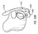
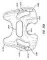
図1~75は、使用者の顔上での位置および使用者の顔から離れた位置の両方にあるマスクアセンブリ2100およびその構成要素を示す。図示のマスクアセンブリ2100は、鼻および口複合型マスクであり、本明細書では鼻-口マスクと称し得る。図示のマスクアセンブリ2100は、使用者の鼻の下側を、鼻に対して横方向に延在する顔の一部に沿ってかつ使用者の口の周りを密封するように設計される。マスクアセンブリ2100は、有利には、使用者の鼻の鼻梁との接触を必要としない。図示の構成では、マスクアセンブリ2100は、使用者の鼻の鼻梁の上側にわたって延在しない。より詳細には、図示のマスクアセンブリ2100は、使用者の鼻の鼻梁に接触しない。さらにより詳細には、図示のアセンブリ2100は、使用者の鼻の鼻梁の前向きの部分と接触しない。いくつかの構成では、アセンブリ2100は、使用者の眼の下縁に沿って延在するほぼ水平の平面よりも垂直方向に高い領域において、顔と接触しない。マスクアセンブリ2100は、使用者の鼻尖の上方に延在してもまたはしなくてもよい。そのため、いくつかの構成では、マスクアセンブリ2100は、鼻尖を覆う。いくつかの構成では、マスクアセンブリ2100のシールは鼻尖を覆う。いくつかの構成では、図示のマスクアセンブリ2100は、好ましくは、使用者の鼻尖を覆い隠さない。いくつかの構成では、またはいくつかの顔の幾何学的形状に従って、使用者の鼻尖は、マスクアセンブリ2100の隣接部分の上方に延在する。 Figures 1-75 show the
図示の通り、マスクアセンブリ2100は、好ましくは、鼻孔の周りに丸みを帯びた隆起を形成するように広がる鼻翼または小鼻の周りに延在しかつその上側を密封するように適合される。図示のマスクアセンブリ2100は、鼻柱(columella)と呼ばれることもある鼻中隔の肉付きのよい外側端部の一部または全体を含み得る、鼻孔への開口部を画成する表面の周りを密封するように適合される。いくつかの構成では、マスクアセンブリ2100は、上方に延在して、使用者の鼻の背部の左および右の側壁の少なくとも一部に沿って密封するように適合される。いくつかの構成では、マスクアセンブリ2100は、使用者の鼻の鼻梁の領域まで上方には延在せずに、背部の左および右の側壁の少なくとも一部に沿って、上方に延在するように適合される。いくつかの構成では、マスクアセンブリ2100の主密封面は、使用者の鼻の下面と、場合により上唇および/または鼻の下面と上唇との間の移行領域とに接触する。マスクの副密封面は、使用者の鼻の側面と、場合により鼻に近い位置にある頬とに接触し得る。そのような主および副密封面は、全ての使用者の顔には接触しないことがあり得る。しかしながら、そのような配置構成は、比較的広範囲の顔の幾何学的形状との好適な密封をもたらし得る。マスクアセンブリ2100は、好ましくは、使用者の口の少なくとも一部の周りも密封する。マスクアセンブリ2100は、使用者の口と鼻との間を密封するように適合されてもまたはされなくてもよい。 As shown, the
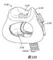
図示の通り、マスクアセンブリ2100は、例えば、ベース、ハウジングまたはマスクシェル2102などのマスク支持体を含む(例えば、図4を参照されたい)。マスクシールまたはクッション2104は、ハウジング2102に取り付けられ、それにより、ハウジング2102がマスクシール2104にある程度の量の支持をもたらし得る。しかしながら、他の構成では、マスクシール2104は、支持体を含まなくてもよく、および関連のインターフェースアセンブリの別の構成要素に直接組み立てられるように適合され得る。いくつかの構成では、ハウジング2102は、図示のハウジングよりも実質的に小さいことができる。例えば、ハウジング2102は、マスクアセンブリ2100を別の構成要素、例えばフレームおよび/または導管コネクタ(例えば、エルボー)に取り付けることができるようにする開口部を画成でき、およびハウジング2102は、マスクアセンブリ2100の他の部分に直接的な支持をもたらすことなく、開口部に局所化され得る。 As shown,
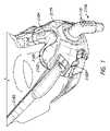
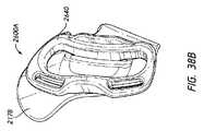
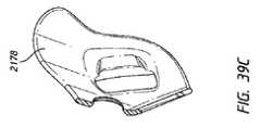
マスクアセンブリ2100は、任意の好適な配置構成のヘッドストラップまたはヘッドギア2180に接続できるようにするフレーム2178と係合し得るか、または他の方法でそれによって支持され得る。マスクアセンブリ2100は、フレーム2178に調整して固定されて、アセンブリを正しい向きにのみすることを可能にする。いくつかの構成では、ヘッドストラップまたはヘッドギア2180は、マスクアセンブリ2100に直接結合され、およびフレーム2178は、他の目的のために使用され得るか、または省略され得る。導管コネクタ2106がまた、ハウジング2102、フレーム2178に取り付けられ得るか、または他の方法で、マスクアセンブリ2100の内部空間に対して支持され、かつそれと連通するように適合され得る。同時に、フレーム2178およびヘッドギア2180は、マスクアセンブリ2100を、使用者の顔上で適所に支持し得る。まとめて、マスクアセンブリ2100、フレーム2178およびヘッドギア2180は、インターフェースアセンブリと呼ばれ得る。マスクアセンブリ2100またはフレーム2178と組み合わせたマスクアセンブリ2100は、インターフェースと呼ばれ得る。 The
図示の導管コネクタ2106は、限定されるものではないが、本出願の他の箇所で説明されるいずれかの方法を含む任意の好適な方法で、フレーム2178および/またはハウジング2102に接続され得る。例えば、限定されるものではないが、コネクタ2106がハウジング2102に接続され得、それにより、コネクタ2106がハウジング2102に対して単軸の周りでまたは複数の軸の周りで旋回、回動また回転できる。いくつの構成では、コネクタ2106は、例えば限定されるものではないが、他の部分を画成するフレーム2178および/またはハウジング2102によって玉継手の一部を画成し得る。玉継手は、任意の好適な構成を有し得る。コネクタ2106は、マスクアセンブリ2100の内部に加圧呼吸ガスを供給するためのガス導管、例えば供給導管などに接続されることを容易にする。場合により、コネクタ2106とガス導管との間の相対的な回転を可能にするスイベル結合または回転結合を含み得る任意の好適なコネクタ2106が使用され得る。 The illustrated
図示の構成では、コネクタ2106は、例えば限定されるものではないがポリカーボネートエルボーなど、通気口を含むエルボーを含む。図示の配置構成では、通気口は、バイアス流れ孔2110を含む。しかしながら、通気口は、スロットなどの他の幾何学的形状もしくは配置構成または例えば構成要素間の制御式の漏れ口を含み得る。通気口は、騒音および/または隙間風を低減させる拡散材料も含み得る。バイアス流れ孔2110は、オリフィスの集合であり、これは、使用者によって呼息された二酸化炭素を再呼吸する可能性を低減させるために、排気しかつCO2を流すように構成される。もっぱらコネクタ2106上にあるバイアス流れ孔2110を示すが、いくつかの構成では、バイアス流れ孔2110は、ハウジング2102、マスクシール2104、またはコネクタ2106、ハウジング2102およびシール2104のいずれかの組み合わせ、またはインターフェースアセンブリまたは関連の呼吸回路のいずれかの他の構成要素に設けられる。バイアス流れ孔2110は、任意の好適な横断面を有することができ、かつシリンダー状の砂時計形状にされる、両方向にテーパが付けられる、完全にまたは部分的にテーパが付けられる、完全にまたは部分的にシリンダー状で、横断面を変化させるような外形にされるなどであり得る。 In the illustrated configuration,
ハウジング2102は、概してマスクアセンブリ2100に、およびより具体的にはマスクシール2104に、ある種の支持構造を提供する。ハウジング2102は、任意の好適な材料から形成され得る。いくつかの構成では、ハウジング2102は、かなり硬質の材料から形成される。いくつかの構成では、ハウジング2102は、ポリカーボネート材料などのプラスチック材料から形成される。いくつかの構成では、マスクアセンブリ2100は、ハウジングから分離されるがそれに取り付けることができるマスクシールクリップを含むマスクシールを含み得る。そのような構成では、マスクシールクリップは、マスクシール2104をハウジング2102に接続する。そのような構成では、マスクシールおよびマスクシールクリップは、別々に形成されて、一緒に固定され得るか、またはマスクシールおよびマスクシールクリップは、単一の構成要素に組み込まれ得る。いくつかの構成では、マスクシールは、マスクシールクリップ上にオーバーモールドされ得、およびいくつかの構成では、マスクシール2104は、ハウジング2102上に直接オーバーモールドされ得、これは、例えば、化学的および/または機械的オーバーモールディングを含み得る。
いくつかの構成では、ハウジング2102は、マスクアセンブリ2100の前方壁のかなりの部分を含む。そのような配置構成は、マスクシール2104に有利なレベルの支持をもたらす。例えば、ハウジング2102は、マスクアセンブリ2100の前方壁の口部分のかなりの部分を含む。いくつかの構成では、ハウジング2102は、全体的に、マスクアセンブリ2100の口部分に制限され、および少なくとも影響を与える程度には、マスクアセンブリ2100の鼻部分に延在しない。そのような配置構成は、マスクシール2104に支持をもたらし得る一方、有利には、マスクシール2104の鼻部分の動きまたは変形を可能にする。他の配置構成では、ハウジング2102は、必要に応じて鼻部分に追加的な支持体を提供するように鼻部分に延在し得る。図示の構成では、ハウジング2102は、中心部分2112から対向する側部部分2116の方に後方に延びる。中心部分2112は、コネクタ2106を受け入れるためのアパーチャ2114を含む。ハウジング2102は、中心部分2112および対向する側部部分2116のあらゆる場所で、全体的にまたは実質的に一定の高さを有し得る。他の配置構成では、ハウジング2102は、マスクシール2104の前部の形状を全体的に模倣する形状を形成することなどにより、高さが変動し得る。ハウジング2102の高さは、マスクシール2104の口部分の高さに実質的に等しいことができる。ハウジング2102の幅は、マスクアセンブリ2100の口部分の全幅の少なくとも約4分の3など、マスクアセンブリ2100の口部分の全幅のかなりの部分を含み得る。ハウジング2102のそのような配置構成は、マスクシール2104の中心および横方向部分を補強し得る。いくつかの構成では、ハウジング2102は、例えば、環状支持リングまたはフレームなど、最小限であり得る。 In some configurations,
マスクシール2104は、使用者の顔に対して密封するように設計される。マスクシール2104は、好ましくは、例えば限定されるものではないが、シリコーンなどの軟質材料で形成される。いくつかの構成では、マスクシール2104の少なくとも複数の部分が、使用者の快適さを向上するためにテクスチャー加工され得る。例えば、いくつかの構成では、図示のマスクシール2104を形成するために使用される型の少なくとも複数の部分が、少なくとも使用者の皮膚に接触するマスクシール2104の領域に表面テクスチャーをもたらすために、ビードブラストされ得る。マスクシール2104の1つ以上の表面をテクスチャー加工する他の技術が使用され得る。いくつかの構成では、表面テクスチャー加工を回避し、かつマスクシール2104の少なくとも顔に接触する面に滑らかな表面テクスチャーをもたらし、これにより、使用者の顔上でのマスクシール2104のグリップ力を向上させかつ密封特徴を改善し得ることが望ましいことがあり得る。
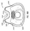
上述の通り、図示のマスクシール2104は、鼻-口マスクシールを含み、そのため、少なくとも1つの口開口部2122および少なくとも1つの鼻開口部2124を含む。いくつかの構成では、マスクシール2104は、口-鼻複合型開口部を含み得る。いくつかの構成では、マスクシール2104は、2つ以上の鼻開口部2124を含み得る。いくつかの構成では、マスクシール2104は、例えばピロー、プロングなどの上部構造内に画成された鼻開口部2124を含み得る。いくつかの構成では、鼻開口部2124は、マスクシール2104のベース構造にオーバーモールドされ得るかまたは他の方法で固定され得る鼻用クッションまたはインサートによって画成され得る。そのような配置構成の例は、本出願人の公報国際公開第2014/062070号に開示されており、その全体を参照により本明細書に援用する。 As mentioned above, the illustrated
少なくとも1つの口開口部2122および少なくとも1つの鼻開口部2124は、好ましくは、マスクアセンブリ2100内に画成される単一チャンバー2125と連通する。図示のマスクアセンブリ2100のチャンバー2125は、ハウジング2102およびマスクシール2104によって少なくとも部分的に画成される。少なくとも1つの口開口部2122は、コネクタ2106を受け入れるかまたはそれと連通するアパーチャ2114に実質的に対向する。少なくとも1つの鼻開口部2124は、少なくとも1つの口開口部2122の垂直に上にあり得る。少なくとも1つの鼻開口部2124は、マスクアセンブリ2100の前後方向において、コネクタ2106のためのアパーチャ2114と、少なくとも1つの口開口部2122との間に位置決めされ得る。少なくとも1つの鼻開口部は、垂直に対して傾斜している軸を有し、かついくつかの配置構成では全体的にコネクタ2106のためのアパーチャ2114を通って延在し得る。 At least one
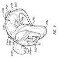
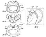
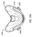
マスクシール2104は、好ましくは、マスクシール2104の中心部分の上部表面2130(例えば、図7を参照されたい)の上方へ上側に延在するパドル2126の対を含む。上部表面2130は、前後方向に、マスクシール2104の鼻表面の中心面に沿って存在する線を画成し得る。そのような線は、全体的に、使用者の顔から離れる方向に、鼻中隔に沿って延在する。パドル2126は、外鼻孔と並行に、およびいくつかの構成では外鼻孔の上方へ上側に延在するように構成される。パドル2126は、外鼻孔の縁および/または鼻の側面に接触し得る。パドル2126またはパドル2126間のマスクシール2104の複数の部分は、使用者の鼻尖を覆ってもまたは覆わなくてもよい。本明細書で説明するように、好ましくは、マスクシール2104は、使用者の鼻の鼻梁に接触しない。
いくつかの構成では、パドル2126は、それぞれエアポケットを含み、このエアポケットは、コネクタ2106から少なくとも1つの鼻開口部2124および少なくとも1つの口開口部2122までマスクアセンブリ2100を通る空気経路と直接流体連通する。パドル2126は、マスクシール2104内の圧力の上昇に応答して体積が拡張し、かつ/または様々な顔および鼻の幾何学的形状に適合するように内側に曲がって、使用者の顔との密封接触を生じることを支援するように構成され得る。パドル2126の拡張は、特に使用者の鼻でのおよびその周りの様々な外形に沿って使用者の顔に対する密封を支援し得る。パドル2126の内側の曲りにより、マスクシール2104の材料をあまり抑制せずにまたはあまり伸張させずに、中心部分(例えば、上部表面2130)を下方に動かすようにできるため、マスクシール2104は、様々な鼻の幾何学形状により良好に一致できる。同様に、下記でより詳細に説明するように、支持構造2163のカットアウト領域2202は、有利には、マスクシール2104内の圧力の上昇に応答して、マスクシールが使用者の顔との密封接触を維持することを可能にし得る。 In some configurations, paddles 2126 each include an air pocket that provides an air path and direct fluid flow through
上部表面2130の上方のパドル2126の高さは、使用者の顔でのマスクシール2104の安定性(例えば、垂直安定性)と、ある範囲の鼻の幾何学的形状に適合できることまたはパドル2126による視覚的な崩壊の減少との間のバランスを望ましくするように選択され得る。概して、より高いパドル2126は、マスクアセンブリ2100の追加的な垂直安定性をもたらす傾向を有する一方、より低いパドル2126は、広範な使用者により良好に適合し、あまり視覚的な崩壊を生じない傾向を有する。いくつかの構成では、パドル高さ2126は、約10mm~約30mmまたは約15mm~約25mmである。いくつかの構成では、パドル高さ2126は、約15mm~約22mmまたは約18mm~約20mmであり、上述の範囲内の任意の値または部分範囲を含む。いくつかの構成では、パドル高さは約18.5mmである。 The height of the
マスクシール2104は、パドル2126のための支持構造または支持体2163も含むことができ、これらの支持体は、マスクシール2104が使用者によって装用されるとき、パドル2126の形状を保持するための機械的剛性および構造をもたらすサスペンション部材またはバネの形態であり得る。支持体2163は、シール材料の厚みのある領域を含み得る。支持体2163は、好ましくは、パドル2126の後方または使用者に接触する面から、パドル2126の前方の面の方にまたはそこまで力を伝達するようなサイズにされ、形状にされ、かつ/または他の方法でそのように構成される。いくつかの構成では、インターフェースは、パドル2126のための支持部分またはカバーを含むことができ、および支持体2163は、パドル2126の後方の面から、支持部分またはカバーに接触または対面するパドル2126またはマスクシール2104の前方の面または他の部分まで力を伝達し得る。いくつかの構成では、支持体2163は、パドル2126の後方の面から、マスクシール2104の別の支持部分(例えば、ハウジング2102)またはインターフェースの方にまたはそこまで力を伝達し得る。支持体2163は、パドル2126またはマスクシール2104の他の関連のまたは隣接する部分が潰れるのに抵抗するかまたはそれを防止して、装着を容易にし、かつ加えられた力(例えば、ヘッドギアの力)に応答してなど、使用者にフィードバックを提供し得る。いくつかの構成では、支持体2163は、有意な内部ガス圧がない場合、パドル2126またはマスクシール2104の他の関連のまたは隣接する部分が潰れるのに抵抗するかまたはそれを防止し得る。 The
支持体2163は、少なくとも、通常の使用中に経験する力に応答して、マスクシール2104のパドル2126の形状を維持することを促進し得、および/またはマスクシール2104の後壁(顔に接触する面を画成する)とマスクシール2104の前壁との間の分離を維持することを促進し得る。さらに、支持体2163は、鼻領域または鼻シール部分2168に支持をもたらし得る。特に、支持体2163は、鼻シール部分2168および/または前面上部2150に構造を提供し、かつそれらの折りじわ、しわまたは潰れを阻止または防止し得る。上述の通り、鼻領域2168および/または前面上部2150は、好ましくは、比較的薄く、マスクシール2104のこれらの部分が使用者の鼻に一致できるようにする。比較的薄い鼻領域2168および/または前面上部2150は、拡張して使用者の鼻の周りを密封し得る。使用者が使用者の鼻をマスクアセンブリ2100に係合するとき、支持体2163は、比較的薄い鼻シール部分2168および/または前面上部2150に隣接してまたはそれらの近くにシール2104の硬質部分または要素を提供して、潰れを阻止または防止する。後面上部2156は、鼻領域2168および/または前面上部2150の潰れを防止することを支援し得る。 The
いくつかの構成では、支持体2163は、使用中にパドル2126の顔に接触する部分にしわまたは折りじわが形成される可能性を低減させる一方、上述のように、横方向内側部分を実用的な制限内で必要に応じて可能な限り薄くできるようにするのに役立つ。支持体2163は、パドル2126の潰れを阻止もしくは防止するか、またはパドル2126の所望の形状を維持することを支援し得る。例えば、支持体2163は、パドル2126の所望の前後形状および/またはパドル2126の横方向または左右形状を維持することを支援し得る。提供される支持レベルは、異なる方向で異なり得る。いくつかの構成では、支持体2163は、シール材料とは別個の部分または別個の構成要素として形成でき、かつ同じまたは異なる材料であり得る。そのような別個の支持体2163は、必要に応じてパドル2126またはマスクシール2104の他の部分に結合され得る。本明細書で開示する支持体2163は、特に、鼻マスクおよび鼻-口複合型マスクの両方を含む鼻下型のマスクアセンブリにおいて有用であり得る。しかしながら、支持体2163は、例えば、限定されるものではないが、使用者の鼻の鼻梁を覆うか、それと接触するかもしくはそれを密封し、かつ/またはT字形部片もしくは他のタイプの額支持体を含むものを含め、他のタイプのマスクアセンブリまたはインターフェースでも用いられ得る。支持体2163は、潰れに対する支持および/または過拡張に対する支持が望まれ得るインターフェースのいずれかの箇所で用いられ得るか、またはそこで使用するように修正され得る。そのような個所は、使用者の鼻と接触またはそれと一緒に延在するシールの部分にまたはその近くにあり得るか、または他の箇所にあり得る。 In some configurations, the
図示の配置構成では、支持体2163の少なくとも一部は、全体的にパドル2126に沿って前後方向に延在する。特に、支持体2163は、パドル2126の上縁に沿って、またはパドル2126の上縁に沿った、横方向外表面部分と横方向内表面部分とが接合する領域もしくはリッジに沿って延在し得る。支持体2163は、鼻領域2168の側面の一部に沿って延在し得る。支持体2163は、全体的に薄くて細長い形状を含み得る。上から見ると、支持体2163は、ほぼ三角形の形状を含むことができ、三角形の底辺が三角形の頂点または点の後方に位置決めされる。所望の支持レベルを達成するために、または隣接するかもしくは直近の構造の所望の形状などの他の設計の検討事項のために他の形状が可能である。支持体2163は、追加的な部分を有して他の支持レベルをもたらし得るか、または他の方向に支持をもたらし得る。例えば、支持体2163は、鼻開口部2124の前方側面または後方側面の一方または両方に沿ってなど、互いに接続し得る。いくつかの構成では、支持体2163は、パドル2126を通って、例えばハウジング2102までなど、完全に延在し得る。 In the illustrated arrangement, at least a portion of
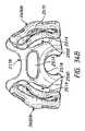
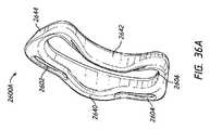
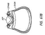
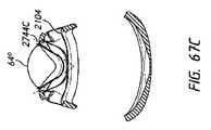
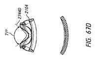
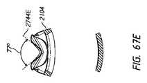
図7~18Bに示すように、パドル2126(または例えば、支持体2163)は、それぞれ薄いおよび/またはカットアウト領域2202を含み得る。カットアウト領域2202は、後方に延在し、かつ各パドル2126の鼻領域の下方に位置決めされる。いくつかの構成では、カットアウト領域2202は、後方に延在し、かつ各パドル2126の鼻領域に隣接して位置決めされる。しかしながら、他の構成では、カットアウト領域2202は、後方に延在し、かつ各パドル2126の鼻領域から横方向にオフセットして位置決めされる。カットアウト領域2202は、マスクシール2104の前面上部2150からマスクシール2104の後面上部2151まで延在して、カットアウト領域2202が各パドル2126の外側部分2210に巻き付くようにし得る。従って、いくつかの構成では、カットアウト領域2202は、全体的に湾曲しており、直線であり、かつ/または可変の湾曲を有する。いくつかの構成では、カットアウト領域2202は、前面上部2150から後面上部2151までおよび/または後面上部2151から前面上部2150まで傾斜され得る。いくつかの他の構成では、カットアウト領域2202は、実質的に平坦であるか、または最小限の傾斜を有する。 As shown in FIGS. 7-18B, paddles 2126 (or, for example, supports 2163) may each include thin and/or cut-out
図示の構成に示すように、カットアウト領域2202は、前面上部2150の少なくとも一部および後面部2151の少なくとも一部にわたって延在する。例えば、カットアウト領域2202は、マスクシール2104の外側部分2110の周りにおよび後面部2151にわたり、口開口部2122の上方の後面上部のほぼ中心に向かって延在する。いくつかの構成では、カットアウト領域2202は、後面上部および/または前面上部の約1/16、1/8、1/4、および/または1/2以上にわたって延在する。いくつかの構成では、カットアウト領域2202は、後面上部2151にわたり、鼻領域2200の鼻開口部2124の外側部の位置には到達しないある距離だけ延在する。 As shown in the illustrated configuration, the
図示の構成では、カットアウト領域2202は、パドル2126の鼻領域の下方に位置決めされる。しかしながら、他の構成では、カットアウト領域2202は、パドル2126の鼻領域の上方および/またはそれと同じ平面に位置決めされ得る。例えば、カットアウト領域2202は、パドル2126の鼻領域の下方の約0.1~0.5mm、0.5~1mm、1~10mm、10~50mm、50mm~1cm、1cm~2cmおよび/または2cm~3cm以上に位置決めされ得る。いくつかの構成では、カットアウト領域2202は、口開口部2122の上側にほぼ隣接して位置決めされる。さらに他の構成では、カットアウト領域2202は、鼻開口部2124の上方、下方および/またはそれと平面的に位置決めされる。しかしながら、いくつかの構成では、カットアウト領域2202は、パドル2126の外側部に沿って延在する。そのような構成では、カットアウト領域2202は、前面上部2150の一部および/または後面上部2151の一部にわたって延在しなくてもよく、およびパドル2126に限定されるかまたは鼻領域2200内で終端してもよい。 In the illustrated configuration,
図7~18Bに示すように、マスクアセンブリ2100の図示のマスクシール2104は、ある範囲および構成の厚さを含む。厚さは、図示のマスクシール2104の異なる領域において異なる特徴を利用するかまたは提供するように様々である。例えば、様々な領域の厚さは、その領域および/またはマスクシール2104全体に対する所望の特性に対処するように選択され得る。そのような特徴は、例えば、マスクシール2104が使用者の顔の幾何学的形状に一致できるようにして、密封性または快適さを高めるようにすること、装着を容易にする著しい内部ガス圧力がなく、および/または内部ガス圧力および/または外圧(例えば、ヘッドギアの力に起因する)に応答してマスクシールの形状を維持すること、または強度または耐久性をもたらすことを含み得る。 As shown in FIGS. 7-18B, the illustrated
上述の通り、マスクシール2104は、異なる厚さの様々な領域を含み得る。そのような配置構成の例は、本出願人の公報国際公開第2015/193821号に説明されており、その全体が参照により本明細書に援用される。概して、マスクシール2104の外表面は、方向の急激な変化がない比較的滑らかな形状の面または曲面を画成する。異なる厚さは、明らかな壁厚さの変化によって生じるか、またはマスクシール2104の内部表面の形状の変化によって生じる。 As mentioned above,
支持体2163は、パドル2126の他の部分と異なる厚さを有することができ、およびパドル2126の他の部分よりも厚さが大きいことができる。いくつかの構成では、支持体2163は、最大厚さを有し得るか、またはマスクシール2104の最大厚さのうちの1つであり得る。いくつかの構成では、支持体2163の一部または全体厚さは、約1.5mm~約3.5mmであり得る。図示の構成では、支持体2163の一部または全体厚さは、約2.5mmであり得る。支持体2163の厚さは、一定または可変であり得る。
いくつかの構成では、パドルのための支持構造2163は、鼻領域2168および前面上部2150よりも厚い。いくつかの構成では、厚さの比較的急激な遷移は、鼻領域2168および前面上部2150およびパドル2126間で生じる。対照的に、外側周辺部2162、パドル2126および後面上部2151間の厚さの遷移は、より漸進的である。さらに、少なくともいくつかの構成では、外側周辺部2162、後面上部2151および口開口部2122間の厚さの遷移は、比較的漸進的である。マスクシール2104の様々な部分が、下記でさらに説明される。 In some configurations, the
使用中、マスクシール2104の顔に接触する領域の少なくともいくつかでのしわの発生を減少させるために、外側周辺部2162が、隣接する部分またはマスクシール2104の他の部分と比較してかなり硬質または比較的硬質であるとき、一般的にマスクシール2104の顔に接触する部分のいくつかまたは全てに隣接する、マスクシール2104の外側周辺部2162は、所望の性能を提供することが見出された。図示の配置構成では、外側周辺部2162は、マスクシール2104の後部のほぼ垂直に延在する部分に沿って延在し、およびマスクシール2104の後部の底部でわずかに内側に巻き付く。さらに、外側周辺部2162は、マスクシールの後ろ向きの側面から、マスクシール2104の横向きの側面の少なくとも一部に巻き付いている。 In order to reduce wrinkling in at least some of the face-contacting areas of the
図示の配置構成では、外側周辺部2162は、口開口部2122の各外側部に配置される。いくつかの構成では、外側周辺部2162は、口開口部2122の全高に沿って延在する。外側周辺部2162の上端は、少なくとも口開口部2122の上端のあたりまで延在し得る。外側周辺部2162の下端部は、口開口部2122の下端部の下方に延在する。上述の通り、いくつかの構成では、外側周辺部2162は、口開口部2122の下方で内側に巻き付いて、外側周辺部2162の複数の部分が、口開口部2122の複数の部分の垂直方向に下側に位置決めされるようにする。 In the illustrated arrangement, an
外側周辺部2162の厚さが比較的厚くなることは、装着を容易にしかつ加えられた力(例えば、ヘッドギアの力)に応答するなどのフィードバックを使用者に提供する著しい内部ガス圧力がないとき、マスクシール2104の潰れに抵抗するかまたはそれを防止することを支援し得る。外側周辺部2162は、マスクシール2104の外側部の湾曲した形状を維持することを促進し得、および/または少なくとも通常の使用中に経験する力に応答してマスクシール2104の後壁(顔に接触する面を画成する)とマスクシール2104の前壁との間の分離を維持することを促進し得る。いくつかの構成では、外側周辺部2162の一部または全体厚さは、約1.0mm~約2.0mmであり得る。図示の構成では、外側周辺部2162の一部または全体厚さは、好ましくは、約1.5mmである。外側周辺部2162の厚さは、外側周辺部2162の境界線内で一貫性があるかまたは様々であり得る。 The relatively thicker thickness of the
いくつかの構成では、カットアウト領域2202の壁厚さは、周囲の密封面(例えば、支持構造2163)と比べて薄い。例えば、カットアウト領域2202のいくつかまたは全ての壁厚さは、周囲の密封面と比べて薄くでき、少なくともいくつかの実施形態では、その全てまたは一部は、支持構造2163の全てまたは一部によって画成され得る。いくつかの構成では、周囲の密封面の壁厚さは、ほぼ3mmである。上述の通り、外側周辺部2162を含む周囲の密封面のいくつかまたは全ての厚さは、約1.0mm~約2.0mmであり得る。しかしながら、支持構造2163のカットアウト領域2202は、例えば、約0.1~0.2mm、0.2~0.3mm、0.3~0.4mm、0.4~0.5mm、0.5~0.6mm、0.6mm~0.7mm、0.7~0.8mm、0.8~0.9mmおよび/または0.9~1.0mm以上の壁厚さを有し得る。図示の構成では、カットアウト領域2202の一部または全体は、好ましくは、約.3mmの壁厚さを有する。カットアウト領域2202の厚さは、カットアウト領域2202の境界線内で一貫性があり得るかまたは様々であり得る。 In some configurations, the wall thickness of
周囲の密封面と比べてカットアウト領域2202の壁厚さが薄いことは、望ましくは、周囲の密封面よりも変形可能および/または圧縮可能である領域を提供し得る。例えば、カットアウト領域は、周囲の密封面よりも硬質でなくかつ/またはより拡張でき得る。これは、例えば、より幅が広い鼻によってなど、パドル2126に横方向の力が加えられるときに望ましいことがあり得る。そのため、カットアウト領域2202は、カットアウト領域2202がないパドル2126、および/または支持構造2163があるかもしくはないパドル2126と比較して、より簡単に圧縮でき、パドル2126の鼻領域に加えられる横方向の力により良好に適応し得る。カットアウト領域2202は、硬質のままである代わりに、パドル2126が圧縮できるようにし、同時にマスクシールアセンブリの構造健全性を維持する(例えば、図10A~10C、図11A~11Bを参照されたい)。この構成は、マスクシールアセンブリを装用している患者にとってより快適であり得る。 A reduced wall thickness of the
いくつかの構成では、マスクシール2104の支持構造2163のカットアウト領域2202は、凹状輪郭2204を含む。例えば、図8は、カットアウト領域2202がカットアウト領域2202の後面部2160に凹状輪郭2204を含むことを示す。図示の構成では、凹状輪郭2204の比較的低い点が各カットアウト領域2202の後面部2160のほぼ中心に位置決めされる。しかしながら、他の構成では、凹状輪郭は、一方の側により接近して位置決めされる。さらに他の構成では、カットアウト領域2202の凹状輪郭2204は、パドル2126の鼻領域により接近して位置決めされる。 In some configurations,
いくつかの構成では、カットアウト領域2202は、カットアウト領域2202の一部または全長に沿って凹状輪郭2204を含む。図示の構成では、凹状輪郭2204の比較的低い点は、カットアウト領域2202の幅のほぼ中心に位置決めされる。しかしながら、他の構成では、凹状輪郭は、一方の側により接近して位置決めされる。さらに他の構成では、カットアウト領域2202の凹状輪郭2204は、パドル2126の鼻領域により接近して位置決めされる。図8に示すように、凹状輪郭2204は、カットアウト領域2202の後面部2160に沿って滑らかに内向きに遷移する。いくつかの構成では、凹状輪郭2204は、比較的短い距離だけマスクシール2104の前面上部2150に向かって内向きに延在する。いくつかの構成では、凹状輪郭2204は、より実質的な距離だけマスクシール2104の前面上部2150に向かって内向きに延在する。いくつかの構成では、凹状輪郭2204は、カットアウト領域2202の後面部2160に沿って下方に延在する。 In some configurations, the
一般的に、パドル2126の拡張は、特に使用者の鼻およびその周りでの変化する表面輪郭2206に沿った、使用者の顔に対する密封を支援し得る。例えば、図8に示すように、鼻領域2168は、表面輪郭2206を含む。表面輪郭2206は、鼻領域2168の内側面に沿って延在し得る。表面輪郭2206は、マスクシール2104の後面上部からマスクシール2104の前面上部2150の中心に向かって全体的に内向きに延在し得る。表面輪郭2206は、望ましくは、患者の快適さを高め、および使用者の顔とのシールが確実に形成されることを支援する一方、特定の使用者に適応するために必要に応じて鼻領域2168の外向きの動きを可能にする。 In general, expansion of the
図9A~9Dは、支持構造2163のカットアウト領域2202の凹状輪郭2204の拡大図を示す。図示の構成に示すように、凹状輪郭2204は、垂直方向に下方に(図9A~9Dに示す向きに対して)、およびマスクシール2104の内部に向かって内向きに延在し得る。そのため、凹状輪郭2204は、十分な力がパドル2126に加えられると、カットアウト領域2202がマスクシール2104の内部に向かって内向きに折り畳むことができるようにする。 9A-9D show enlarged views of the
一般的に、凹状輪郭2204、表面輪郭2206および/またはカットアウト領域2202の薄い壁の厚さは、材料を減少させることに貢献し得る。これにより、望ましくは、嵩を減らし、および患者の快適さを高め得る。いくつかの構成では、凹状輪郭2204は、カットアウト領域2202の壁がマスクシールアセンブリの内部チャンバー2125に向かって内向きに折り畳むことを促し得る。これは、有利には、マスクシール2104が患者の顔にもたれて折り畳むため、嵩を減らし得る。同様に、カットアウト領域2202の凹状輪郭2204は、マスクシール2104が使用者によって装用されたときに使用者の顔とのシールがより良好となるため、漏れを最小限にすることを支援し得る。例えば、マスクシール2104が横方向に拡張するときに外向きに拡張しおよびまたは外向きに急に出るのではなく、有利には、カットアウト部分2202は、内向きに折り畳んで使用者の顔との係合を維持し、かつマスクシール2104が望ましくない位置に移ることを防止し得る。 In general, the
いくつかの構成では、凹状輪郭2204は、パドル2126に力が加えられたとき、カットアウト領域2202をより良好に圧縮できるようにする。上述の通り、凹状輪郭2204は、パドル2126に横方向の力が加えられると、カットアウト領域2202が横方向および/または垂直方向にかつ内向きに折り畳むことができるようにし得る。 In some configurations,
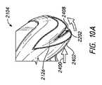
例えば、図10A~10Cおよび図11A~11Bは、マスクシール2104のカットアウト領域2202を示す、マスクアセンブリの上面図を示す。この例では、パドル2126の鼻領域2402に一定の横方向の力2400が加えられる。いくつかの構成では、横方向の力2400は、使用者の鼻が鼻領域2402のニュートラルな幅(例えば、鼻領域2402に加えられる横方向の力がないかまたは最小限であるとき)よりも広いことに起因する。しかしながら、図示しない他の構成では、力は、いずれの方向にも加えられ得、および/または変更され得る。図示の例に示すように、力2400がパドル2126に加えられると、カットアウト領域2202は、圧縮し得る。図10Aは、力が加えられていないかまたはほとんど加えられていないときの例示的な構成を示す。図示の通り、支持構造2163は、内側領域2404および外側領域2406を含み、これらは、協働して、カットアウト領域2202を画成する。そのような構成では、カットアウト領域2202は、内側領域2404と外側領域2406とを分離する。パドル2126に力が全く加えられていないかまたは小さい力が加えられているとき、内側領域2404および外側領域2406の外側端部は、間隙2408によって離間される。図10Bは、横方向の力2400がパドル2126の鼻領域に加えられたときのマスクシール2104の構成を示す。図示の構成に示すように、内側領域2404は、カットアウト領域2202の外側領域2406の方に圧縮する。図示の構成では、外側領域2406は、横方向の力2400がパドル2126の鼻領域に加えられたとき、比較的静止した状態のままである。図10Bに示すように、間隙2408のサイズは、カットアウト領域2202の内側領域2404が圧縮されるにつれて小さくなる。パドル2126が圧縮されるにつれて、内側領域2404は、外側領域2406の方に動く。いくつかの構成では、鼻領域に加えられる力の量に依存して、カットアウト領域2202の内側領域2404は、外側領域2406に触れず、かつ/またはそれと重なり合わない。しかしながら、図10Cに示すように、内側領域2404は、外側領域2406と触れ得、かつ/または少なくとも部分的に重なり合い得る。 For example, FIGS. 10A-10C and 11A-11B show top views of the mask assembly showing the
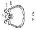
いくつかの構成では、マスクシール2104は、鼻密封面に柔軟性をもたらして、使用者の様々な鼻の幾何学的形状および異なるサイズの鼻領域、特に様々な鼻の幅の要求を満たし得る。いくつかのそのような構成では、本明細書で説明するシール2104は、使用者の鼻の外側で内向きに挟むことにより、使用者の下方の鼻表面とのシールを向上させる。 In some configurations, the
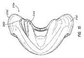
図12~15に示すように、マスクシールは、他のマスクシールと比べて狭くなった鼻領域幅2410を含み得る。鼻領域幅2410が狭いことは、望ましくは、使用者の鼻の側面との確実な係合が増した感じをもたらし得る。例えば、鼻領域幅2410は、マスクシール2104の上部の幅の約2分の1であり得る。いくつかの構成では、鼻領域幅2410は、マスクシール2104の上部の幅の約1/4である。いくつかの構成では、鼻領域幅2410は、マスクシール2104の中心からマスクシール2104の外側周辺部2162に向かって外向きに、口開口部2122の横方向の幅よりも短い距離だけ延在し得る。いくつかの構成では、鼻領域幅2410は、マスクシール2104の中心からマスクシール2104の外側周辺部2162に向かって外向きに、口開口部2122の横方向の幅とほぼ同じおよび/またはそれを上回る距離だけ延在する。いくつかの構成では、鼻領域幅2410は、マスクシール2104の中心からカットアウト領域2202まで外向きに延在する。 As shown in FIGS. 12-15, the mask seal may include a narrowed
いくつかの構成では、全鼻領域幅2412は、約20mm~25mmの幅、25mm~30mmの幅、30mm~35mmの幅、35mm~40mmの幅、40mm~45mmの幅、45mm~50mmの幅および/または50mm以上の幅である。好ましくは、全鼻領域幅2412は、約40mmの幅である。 In some configurations, the total
いくつかの構成では、全鼻領域幅2412が狭いことにより、装用時に使用者の鼻の側面との係合を増し得る。そのため、上述の通り、マスクシール2104は、使用者の顔とのより良好なシールを提供し得る。そのような構成は、使用者が、マスクシール2104が正しく位置決めされ、かつ/または使用者の鼻と適切に密封されると感じることができるようにする。いくつかの構成では、マスクシール2104のパドル2126は、使用者の鼻に加えられる密封力を高めることにより、使用者の鼻で内向きに挟み得る。 In some configurations, a narrower overall
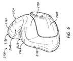
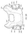
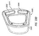
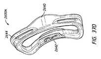
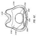
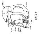
いくつかの構成では、マスクアセンブリは、前面部2420を含む。前面部2420は、窪んだ前面2430および1つ以上のスカラップ状の外側部2440を含み得る。例えば、図16は、ハウジングまたはマスクシェル2102によって形成された窪んだ前面2430を含む、マスクアセンブリ2100の例を示す。窪んだ面2430は、マスクシール2104の前側に位置決めされ得、およびフレーム2178を受け入れるように構成され得る。窪んだ前面2430は、シール2104が接合されるハウジングまたはマスクシェル2102の周囲の一部または全体に沿って形成され得る。図示の例では、窪んだ前面2430は、前面部2420の表面に段を形成する。窪んだ前面2430は、全体的に、ハウジング2102の周囲の側面および下縁に沿って延在する。いくつかの構成では、段は、その長さに沿って深さにテーパが付けられており、ハウジング2102の周囲の上縁に沿って段が全くまたはほとんどないようにして、シール2104がハウジング2102の周囲の上縁に沿ってハウジング2102と同一平面にあるようにする。 In some configurations, the mask assembly includes
段の深さは、シール2104のサイズに依存し得る。例えば、シール2104は、ある範囲の顔の寸法および顔の幾何学的形状である使用者に適合するようにある範囲のサイズで提供され得る。いくつかの構成では、シール2104は、単一サイズのハウジング2102に接合される。いくつかの構成では、ハウジング2102に対してシール2104のサイズが異なることにより、段の深さを決定する。いくつかの構成では、窪んだ前面2430は、一定の深さまたは可変深さで窪んでいる。例えば、窪んだ前面2430の深さは、窪んだ前面2430の表面全体を通して一定であり得る。しかしながら、いくつかの構成では、上部の窪んだ面2432(下記でより詳細に説明する)は、窪んだ前面2430の残りの領域の深さを下回るおよび/または上回る深さで窪んでいる。 The depth of the step may depend on the size of
いくつかの構成では、前面部2420は、シール2104内に形成された上部の窪んだ面2432を含む。上部の窪んだ面2432は、前面上部2150に位置決めされ得る。図示の構成では、上部の窪んだ面2432は、パドル2126の前側に沿って位置決めされる。上部の窪んだ面2432は、マスクシール2104の前側面2422の外側周辺部2162に沿って延在し得る。上部の窪んだ面2432は、マスクシール2104の側面の周りで後方に延在し得る。いくつかの構成では、上部の窪んだ面2432は、実質的にマスクシール2104の外側周辺部2162の周りで巻き付いている。いくつかの構成では、上部の窪んだ面2432は、外側周辺部2162の一部にのみ位置決めされる。例えば、上部の窪んだ面2432は、シール2104の両側で前側面2422の高さのおよそ半分だけ下方に延在し得る。いくつかの構成では、上部の窪んだ面2432は、前側面2422の半分を下回っておよび場合により前側面2422の約1/3だけ下方に延在する。 In some configurations,
いくつかの構成では、上部の窪んだ面2432は、周辺の湾曲に沿って延在する前面上部2420の上方周辺またはパドル2126の上縁間に段付き移行部を形成する。いくつかの構成では、段付き移行部は、一定の深さまたは可変深さで延在する。例えば、段付き移行部の深さは、前面上部2420の上方周辺と窪んだ前面2430との間の段付き移行部全体を通して一定であり得る。しかしながら、いくつかの構成では、段付き移行部は、変化する。例えば、段付き移行部は、テーパが付けられ得る。この配置構成では、深さは、段付き移行部の下方または横方向末端部において最小であり得る。しかしながら、いくつかの実施形態では、深さは、段付き移行部の上方末端部において最小であり得る。 In some configurations, the upper recessed
段付き移行部の深さは、マスクシールのサイズを含むいくつもの要因に依存し得る。例えば、段付き移行部のテーパの深さは、より大型のマスクシールではより深く、またはより小型のマスクシールではより浅いことができる。いくつかの構成では、前面上部2420は、複数の上方の角を含む。例えば、前面上部2420は、第1の上方の角および/または第2の上方の角を含み得る。複数の上方の角は、パドル2126の前面部に形成され得る。複数の上方の角は、前面上部2420の周辺に沿って延在する上部の窪んだ面2432の周囲の全てまたは一部を画成し得る。 The depth of the stepped transition can depend on a number of factors, including the size of the mask seal. For example, the taper depth of the stepped transition can be deeper for larger mask seals or shallower for smaller mask seals. In some configurations, the
いくつかの構成では、段付き移行部の深さおよび/または段付き移行部のテーパは、全体的に上方の角間(例えば、第1の上方の角と第2の上方の角との間)に位置決めされた中心上部と比べて複数の角において大きい。 In some configurations, the depth of the stepped transition and/or the taper of the stepped transition is generally between the upper corners (eg, between the first upper corner and the second upper corner). It is larger at several corners compared to the central top positioned at .
いくつかの構成では、窪んだ前面2430および/または上部の窪んだ面により、フレーム2178をマスクシール2104に挿入できるようにする。例えば、上部の窪んだ面2432は、フレーム2178の全てまたは一部を受け入れ得る。そのため、いくつかの構成では、上部の窪んだ面2432の段付き移行部は、フレームの厚さ以上である最大深さを有する。同様に、窪んだ前面2430は、フレーム2178の全てまたは一部を受け入れ得る。これらの構成は、有利には、幾分平坦な仕上げを提供し得、これは、使用者にとってより見た目が美しい。いくつかの構成では、マスクシール2104の視覚的なサイズが小さくされ得、かつ/またはマスクシールに使用される材料の量が削減され得る。そのため、いくつかの構成では、マスクシール2104は、使用者にとってあまり嵩張らず、および/またはあまり目立たない(例えば、図17を参照されたい)。 In some configurations, a recessed
いくつかの構成では、上部の窪んだ面2432は、いくつかの密封クッションサイズでのみ提供され得る。例えば、上部の窪んだ面2432は、いくつかの中型または大型のマスクシール2104のみに提供され得る。いくつかの構成では、上部の窪んだ面2432は、いくつかの小型または中型のサイズのマスクシール2104に提供される。いくつかの構成では、上部の窪んだ面2432は、全てのサイズのマスクシール2104に存在し得る。上部の窪んだ面2432の深さは、マスクシール2104のサイズに依存して変化し得る。いくつかの構成では、窪んだ上部の深さは、小型および/または中型のマスクシール2104のためのフレーム2178の厚さと実質的に同じであり得、および深さは、大型のマスクシール2104(例えば、小型および/または中型のサイズのマスクシール2104よりも大きいサイズ)のためのフレーム2178の厚さを上回り得る。そのような構成では、これは、フレーム2178に覆いかぶさりかつ/またはそれを越えて延在するマスクシール2104を生じ得る。いくつかの構成では、上部の窪んだ面2432は、フレーム2178が複数のマスクシール2104に対して大き過ぎたりまたは小さ過ぎたりすることなく、複数の様々なサイズのマスクシール2104と一緒に単一サイズのフレームを使用できるように構成される。 In some configurations, the upper recessed
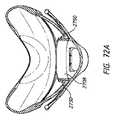
いくつかの構成では、上部の窪んだ面2432は、鼻密封面をより良好に支持する。例えば、図17は、フレーム2178と、上部の窪んだ面2432に差し込まれたおよび/または上部の窪んだ面内に位置決めされたフレームパドル2179とを示す。図示の構成に示すように、フレームパドル2179は、上部の窪んだ面2432内に位置決めされ得る。この構成では、フレームパドル2179の外表面は、上部の窪んだ面2432と同一平面に載置される。この配置構成は、マスクシール2104の前側面2422およびパドル2126にさらなる剛性を提供することにより、鼻密封面を追加的に支持し得る。いくつかの構成では、フレームパドル2179は、望ましくは、シールパドル2126を支持する。そのような構成では、フレームパドル2179は、シールパドル2126が使用時に使用者の鼻から離れて撓むことを防止することを促進し得る。いくつかの構成では、この配置構成は、マスクシール2104が過度に変形される場合、フレームパドル2179が使用者の顔に接触するかまたは食い込むことを防止することを促進し得る。そのため、いくつかの構成では、窪んだ前面2430は、有利には、マスクシール2104を長い時間にわたってその構造に維持できるようにし、およびマスクシール2104の耐久性を高め得る。いくつかの構成では、窪んだ前面2430は、単一サイズのフレーム2178を、様々なサイズを有するマスクシール2104で使用できるようにする。そのため、いくつかの構成では、窪んだ前面2430は、マスクアセンブリの製造コストを削減する。 In some configurations, the upper recessed
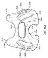
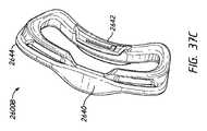
図18Aおよび図18Bは、スカラップ状の外側部2440を含むマスクシール2104の例を示す。スカラップ状の外側部2440は、有利には、マスクシール2104の材料の量を削減でき、およびより見た目が美しいかまたは視覚的に小さいマスクシール2104を提供し得る。図示の構成に示すように、マスクシール2104の外壁は、マスクシール2104の外側周辺部2162に沿って滑らかに移行する。しかしながら、他の構成では、外側周辺部2162は、少なくとも3つの別個のセクション(例えば、上部、中心部分および下部)を含むことができ、かつ外側周辺部2162は、各セクション間を滑らかに移行しないことがあり得る。 18A and 18B show an
図示の構成では、スカラップ状の外側部2440は、マスクシール2104の側面に沿って凹状部分を形成する。スカラップ状の外側部2440は、マスクシール2104の外側周辺部2162に沿ってパドル2126の下方に位置決めされ得る。いくつかの構成では、スカラップ状の外側部2440は、パドル2126の底部と少なくとも部分的に重なり合って位置決めされる。いくつかの構成では、スカラップ状の外側部2440は、全体的にパドル2126の下方に位置決めされる。いくつかの構成では、スカラップ状の外側部2440の凹状部分の中心2442は、口開口部2122の頂部とほぼ整列される。いくつかの構成では、凹状部分の中心2442は、口開口部2122の上方であるが、鼻領域2168の下方に位置決めされる。いくつかの構成では、凹状部分の中心2442は、鼻領域2168の上方に位置決めされる。 In the illustrated configuration, the scalloped
いくつかの構成では、スカラップ状の外側部2440は、マスクシール2104の外側周辺部2162のおよそ2分の1に沿って延在する。いくつかの構成では、スカラップ状の外側部2440は、マスクシール2104の外側周辺部2162のおよそ1/8、1/4、1/3、3/4以上に沿って延在する。 In some configurations, scalloped
図示の構成に示すように、スカラップ状の外側部2440は、鼻領域2168を追加的に垂直方向に支持し得る。例えば、スカラップ状の外側部2440は、鼻領域に横方向の力が加えられるときおよび/またはマスクシール2104内の圧力が上昇するとき、追加的に支持し得る。例えば、スカラップ状の外側部2440は、マスクシール2104のいくつかある部分の中で特に、有利には、頬からマスクシール2104の側部にあるフレーム2178に荷重を伝達することを支援し得、それにより使用者の顔との係合を維持することを促進する。そのため、スカラップ状の外側部2440は、使用者の鼻とマスクシール2104との間の密封性を改善し得る。 As shown in the illustrated configuration, the scalloped
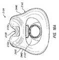
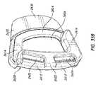
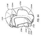
図19Aおよび図19Bは、ハウジングまたはマスクシェル2102によって形成された窪んだ前面2430を含むマスクアセンブリ2100の例を示す。窪んだ前面2430は、マスクシール2104の前側に位置決めされ得、かつフレーム2178の様々な構成を受け入れることができる。例えば、図19Aおよび図19Bに示すように、フレーム2178およびフレームパドル2179は、シール2104によって全体または一部が画成され得る上部の窪んだ面2432に差し込まれ、かつ/または上部の窪んだ面内に位置決めされる。 19A and 19B show an
いくつかの構成では、ハウジング2102は、バイアス通気口2502を含み得る。バイアス通気口2502は、複数のオリフィスを含み得、これらのオリフィスは、使用者によって呼息された二酸化炭素を再呼吸する可能性を低減させるために排気しかつCO2を流すように構成される。もっぱらハウジング2102上にあるバイアス通気口2502のオリフィスを示すが、いくつかの構成では、バイアス通気口2502は、マスクシール2104、エルボー2520もしくは他の導管コネクタ、またはハウジング2102、マスクシール2104、エルボー2520のいずれかの組み合わせ、またはインターフェースアセンブリもしくは関連の呼吸回路のいずれかの他の構成要素に設けられ得る。オリフィスは、任意の好適な横断面を有することができ、かつシリンダー状の砂時計形状にされるか、両方向にテーパが付けられるか、完全にもしくは部分的にテーパが付けられるか、完全にもしくは部分的にシリンダー状であるか、または横断面を変化させるような輪郭にされるなどであり得る。オリフィスの横断面は、オリフィスを通る排気を増加または減少させ得る。 In some configurations,
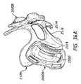
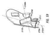
いくつかの構成では、フレーム2178は、エルボー2520を取り付け得、かつ/または他の方法で含み得る。図19Aおよび図19Bは、エルボー2520がフレーム2178に取り付けられるマスクアセンブリ2100の例を示すが、いくつかの構成では、エルボーは、いくつかあるマスク構成要素の中で特に、マスクハウジング2102および/またはマスクシール2104に直接取り付けられる。エルボーは、フレーム2178および/またはハウジング2102に取り外し可能にかつ/または永久に取り付けられ得る。エルボー2520は、非水平のコネクタを形成し得る。例えば、エルボー2520は、曲り部を含み得る。いくつかの構成では、エルボー2520は、いくつかある範囲の中で特に、約10~20度、20~30度、30~40度、40~50度、50~60度、60~70度、70~80度および/または80~90度の角度で曲がる。そのような構成は、望ましくは、マスクアセンブリの嵩高性を減少させ、材料を削減し、および/または空気の流れの向きを所望の方向に変え得る。いくつかの構成では、エルボー2520は、水平、垂直または直線である。 In some configurations,
エルボー2520は、上部および下部を含み得る。上部および下部は、上述のような曲り部によって分離され得る。エルボー2520は、特に、フレーム接続スロット2532、保持用ノッチ2534および入口コネクタ2530などの様々な接続特徴を含み得る。入口コネクタ2530は、エルボー2520の上部を形成して、入口コネクタ2530がマスクハウジング2102の入口2510と接続し得るようにする。入口コネクタ2530は、スナップフィット、圧入、締り嵌めおよび/または他の嵌合構成により、エルボー2520を入口2510に取り外し可能に接続し得る。従って、いくつかの構成では、エルボー2520は、一方の端部(例えば、下部)においてガス供給導管(図示せず)に接続され得、およびエルボー2520の別の端部(例えば、上部)に位置決めされた入口コネクタ2530は、流路を提供し、この流路を通して、加圧ガスの流れがマスクシール2104の内部チャンバー2125を通して使用者にもたらされる。
フレーム接続スロット2532は、エルボー2520内にスロットまたはカットアウト部によって形成され得る。いくつかの構成では、フレーム接続スロット2532は、エルボー2520の隣接する表面部分から外向きに延在するリブなどの複数の突起によって形成され得る。例えば、図26および図28に示すように、エルボー2520は、エルボー2520から外向きに延在する2つのリブを含んで、フレーム2178のエルボーコネクタ2516を受け入れかつ/または保持する。図21Aおよび図21Bに示すように、フレーム接続スロット2532は、エルボー2520の上部の端部からオフセットして位置決めされ得る。いくつかの構成では、フレーム接続スロット2532は、曲り部の一方の側部においてエルボー2520の下部に位置決めされる。フレーム接続スロット2532は、エルボー2520の周りに完全に巻き付き得る。いくつかの構成では、図示の通り、フレーム接続スロット2532は、エルボー2520の一部の周りにのみ延在する。
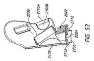
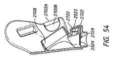
いくつかの構成では、エルボー2520は、窒息防止(A-A)弁2522を含み得る。A-A弁2522は、周囲空気がマスク2100に入ることができるようにする流路を提供し得る。例えば、場合により、流れ発生器がマスクにガスを供給できない場合、弁2522は、使用者に周囲空気へのアクセスをもたらす。 In some configurations,
A-A弁2522は、いくつかある構成要素の中で特に、弁フラップ2524、弁シートまたはリテーナ2526および弁口2536を含み得る。弁口2536は、大気からマスクシール2104の内部チャンバー2125に空気が流れるための経路を提供するために1つ以上の開口部を含み得る。弁口2536は、エルボー2520の一方の端部に位置決めされ得る。例えば、弁口2536は、エルボー2520の下部の後側2540に位置決めされ得、弁口2536が全体的にマスクシール2104またはマスクシール2104の凹状の前面2508の方に対面する開口部を形成するようにする(下記で説明するように)。いくつかの構成では、弁口2536は、エルボー2520の入口コネクタ2530の下方に位置決めされる。いくつかの構成では、弁口2536は、マスクシール2104の凹状の前面2508に対してほぼ平行である。いくつかの構成では、弁口2536は、マスクシール2104の凹状の前面2508に向かって下方に角度が付けられる。 The
弁フラップ2524は、エルボー2520におよび/または弁シート2526の少なくとも一部に収まるように位置決めされ得る。弁フラップ2524は、弁口2536を開閉して、弁口2536を通って空気が流れることができるようにし得る。例えば、流れ発生器が使用者にマスクシール2104を通る空気流れをもたらすとき、弁フラップ2524は、弁シート2526に対して開放されており、それにより弁口2536を閉鎖する。流れ発生器がマスクシール2104に空気流れをもたらさないとき、弁フラップ2524は、弁シート2526に対して閉鎖されており、および弁口2536は、開放されて、使用者が弁口2536を通して周囲空気を吸息できるようにする。弁シート2526は、弁フラップ2524を動作可能位置に支持し得る。いくつかの構成では、弁シート2526は、弁フラップ2524が反転するかまたはエルボー2520から下方に延在することを防止するストッパを画成する。下記でより詳細に説明するように、いくつかの構成では、弁2522を含むエルボー2520は、マスクシール2104の凹状の前面の前方に位置決めされ得る。
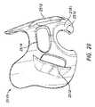
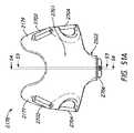
図20は、マスクアセンブリ2100に実装され得、かつ本明細書で説明するハウジング2102の実施形態に接続され得る例示的なフレーム2178を示す。フレーム2178は、様々な配置構成によってハウジング2102に取り付けられ得る。例えば、フレーム2178は、マスクシール2104内に摺動し得、および/またはいくつかある好適な取り付け配置構成の中で特に、スナップフィットまたは圧入により、マスクシール2104に取り付けられ得る。上述の通り、フレーム2178は、上部の窪んだ面2432を含むマスクシール2104の窪んだ前面2430に収まり得る。いくつかの構成では、フレーム2178は、マスクシール2104から繰り返し取り外し可能であり、マスクシール2104およびフレーム2178の一方または両方を交換できるように構成される。しかしながら、いくつかの構成では、フレーム2178は、マスクシール2104に永久に取り付けられ得る。 FIG. 20 shows an
いくつかの構成では、フレーム2178は、いくつかある特徴または構成要素の中で特に、少なくとも1つのヘッドギアコネクタ2512、通気アパーチャ2514および/またはエルボーコネクタ2516を含み得る。少なくとも1つのヘッドギアコネクタ2512は、ヘッドギアに接続し得、かつ/またはそれを受け入れ得る。いくつかの構成では、ヘッドギアコネクタ2512は、フレーム2178に形成され得る。例えば、フレーム2178は、1個、2個、3個、4個、5個および/または6個以上のヘッドギアコネクタ2512を含み得る。図20に示すように、図示のフレーム2178は、対向するヘッドギアコネクタ2512の対を含み、これらのヘッドギアコネクタは、ヘッドギアのコネクタクリップなど、ヘッドギアの少なくとも一部をそれぞれ受け入れるスロットを形成する。 In some configurations,
少なくとも1つのヘッドギアコネクタ2512は、フレーム2178の前側に沿って位置決めされ得る。例えば、少なくとも1つのヘッドギアコネクタ2512は、フレーム2178の前側から外向きに(例えば、前方および/または横方向外向きに)延在し、およびヘッドギアを接続するためにフレーム2178のアパーチャの境界線を少なくとも部分的に画成し得る。図20に示すように、ヘッドギアコネクタ2512は、高さおよび/または幅方向においてフレーム2178の前側の一部のみに沿って延在し得る。ヘッドギアコネクタ2512は、フレーム2178の頂部側とフレーム2178の下側との間で垂直に延在し得るか、または角度が付けられ得る。図示の配置構成では、ヘッドギアコネクタ2512の上方端部は、ヘッドギアコネクタ2512の下方端部に対して前方および/または内側に位置決めされる。ヘッドギアコネクタ2512は、少なくとも部分的にパドル2126および/またはフレーム2178の鼻領域のそれぞれの下方に位置決めされ得る。いくつかの構成では、ヘッドギアコネクタ2512は、ハウジング2102またはマスクアセンブリ2100の他の構成要素に位置決めされ得る。 At least one
図20に示すように、フレーム2178は、バイアス通気口2502に適応するかまたは受け入れるような形状にされた通気アパーチャ2514を含み得る。従って、いくつかの構成では、通気アパーチャ2514は、バイアス通気口2502と位置合わせする。いくつかの配置構成は、有利には、上述の通り、排気がフレーム2178を通って大気へ通過可能にし得る。例えば、バイアス通気口2502は、好ましくは、ハウジング2102に設けられ、かつフレーム2178および/またはヘッドギアにあるいずれかの開口部と連通し得るかまたは位置合わせし得る。いくつかの構成では、バイアス通気口2502は、フレーム2178によって覆われていないハウジング2102の少なくとも一部内またはフレーム2178とハウジング2102との間に画成された空間内に配置される。いくつかの構成では、バイアス通気口2502は、フレーム2178によって少なくとも部分的に覆われ得る。そのような配置構成は、排気がフレーム2178に接触する場合、流量に影響を及ぼし得る。 As shown in FIG. 20,
いくつかの構成では、フレーム2178がマスクシール2104に接続されたとき、バイアス通気口2502は、少なくとも部分的にフレーム2178の通気アパーチャ2514を通って延在し得る(例えば、図19Aおよび図19Bを参照されたい)。いくつかの構成では、バイアス通気口2502は、バイアス通気口2502が通気アパーチャ2514内に位置決めされたとき、フレーム2178と同一平面に位置決めされる。 In some configurations, the
いくつかの構成では、フレーム2178は、エルボーコネクタ2516を含み得る。エルボーコネクタ2516は、図22A~23Bに示すように、エルボー2520を受け入れ得、かつ/またはそれに接続し得る。エルボーコネクタ2516は、エルボー2520の少なくとも一部を受け入れるように構成され得るフレーム2178の下縁に位置するカットアウトによって画成され得るかまたはそれを含み得る。例えば、エルボーコネクタ2516のカットアウト部は、エルボー2520に接続して、フレーム2178がエルボー2520のフレーム接続スロット2532に収まるようにし得る。 In some configurations,
いくつかの構成では、エルボーコネクタ2516は、スナップフィット、圧入、締り嵌めおよび/または他の嵌合構成により、エルボー2520に接続し得る。例えば、エルボーコネクタ2516は、好ましくは、保持用隆起2518の対を含み得る。保持用隆起2518は、エルボーコネクタ2516の下方の角に互いに対向して位置決めされ得る。保持用隆起2518は、エルボー2520の対応する接続特徴、例えば保持用ノッチ2534と係合し得る。保持用ノッチ2534は、エルボー2520のフレーム接続スロット2532の下方端部に位置決めされ得る。いくつかの構成では、フレーム2178は、特に、溶接、オーバーモールドおよび/または接着剤などの接続手段により、エルボー2520に永久的に接続され得る。 In some configurations,
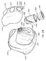
上述の通り、エルボー2520は、フレーム2178に接続し得る。いくつかの構成では、図22A~23Bに示すように、エルボー2520は、フレーム2178がマスクシール2104に接続される前にフレーム2178に接続し得る。例えば、エルボーは、エルボーコネクタ2516のカットアウト部内に摺動して、エルボーコネクタ2516がフレーム接続スロット2532と位置合わせするようにし得る。エルボーコネクタ2516がフレーム接続スロット2532内に摺動すると、保持用隆起2518は、対応する保持用ノッチ2534と位置合わせし得る。従って、エルボー2520はフレーム2178によって保持されてサブアセンブリを形成し得、その後、マスクシール2104に結合され得る。
いくつかの構成では、図21Aおよび図21Bに示すように、例えば、エルボー2520は、エルボー2520の入口コネクタ2530によってハウジング2102の入口2510に直接接続する。いくつかの構成では、エルボー2520は、フレーム2178がエルボー2520に接続される前またはその後にハウジング2102に接続し得る。しかしながら、他の構成では、エルボー2520は、最初にフレーム2178に接続され、その後、エルボー2520/フレーム2178サブアセンブリがハウジング2102に接続され得る必要がある。いくつかの構成では、エルボー2520は、ハウジング2102とフレーム2178との間を接続し得る。例えば、そのような構成では、フレーム2178は、エルボー2520によってもたらされた接続がない状態でハウジング2102に接続しなくてもよい。いくつかの構成では、エルボーは、マスクシール2104の密封面2504に対してほぼ垂直である平面2506から下方に角度が付けられる方向において、ハウジング2102に接続しかつ/またはそこから切り離す。例えば、平面2506は、エルボー2520がフレーム2178に接続される方向に対して実質的に垂直であり得る。いくつかの構成では、平面2506は、フレーム2178がエルボー2520に接続される方向に対して実質的に垂直であり得る。エルボー2520は、スナップフィット配置構成などのいくつもの接続配置構成により、ハウジング2102に取り外し可能に取り付けられ得る。 In some configurations, for example,
エルボー2520がハウジング2102に接続されると、エルボー2520は、非回転可能であり得る。例えば、フレーム2178、エルボー2520およびハウジング2102が組み立てられたとき、フレーム2178は、ハウジング2102に対して回転できなくてもよい。いくつかの構成では、ハウジング2102とエルボー2520との間の接続配置構成は、有利には、CPAPホースによって生成されたホースの引きずり力がマスクから隔離され得るようにする。そのような構成では、可撓性導管(図示せず)は、CPAPホースをエルボー2520に接続する中間構成要素を形成し得る。いくつかの構成では、ハウジング2102とエルボー2520との間の接続配置構成は、望ましくは、より薄型のマスクアセンブリ2100を提供するために角度が付けられ、使用者が装用するのにあまり目立たないようにする。そのようなものとして、エルボー2520は、従来のマスクアセンブリと比較して装用時に使用者の顔からあまり遠くに延在しなくてもよい。そのような構成は、エルボー2520およびマスクアセンブリ2100上での潜在的なホースの引きずりに起因するモーメントアームを減少させ得る。 When
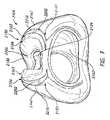
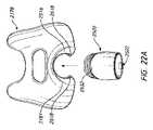
いくつかの構成では、ハウジング2102は、入口2510を少なくとも部分的に囲む凹状の前面2508を含む(例えば、図21Bおよび図24を参照されたい)。例えば、凹状の前面2508は、入口2510の下方にある凹状の前面2508の部分が、入口2510の上方にある凹状の前面2508の部分より広くなるように入口2510に対してオフセットされ得る。いくつかの構成では、入口2510の最下点の下方にある凹状の前面2508の部分の面積は、入口2510の中心の上方にある凹状の前面2508の部分の面積よりも少なくとも2倍、3倍、4倍および/または5倍大きい。いくつかの構成では、入口2510の下方にある凹状の前面の部分の面積は、入口2510の側面までの凹状の前面の部分よりも大きい。 In some configurations,
凹状の前面は、有利には、マスクアセンブリ2100を位置合わせすることを支援して、凹状の前面により、組立中にエルボー2520および/またはフレーム2178をハウジング2102の入口2510内に方向付けるようにし得る。 The concave front surface may advantageously assist in aligning the
組み立てられると、図26~28に示すように、例えば、凹面2508は、エルボー2520の後側2540から離間される。従って、一方の側のエルボー2520の後側2540またはフレーム2178の内面と、他方の側のハウジング2102との間に間隙が形成される。いくつかの構成では、間隙は、弁口2536が開放位置にあるとき、内部マスク呼吸チャンバーに対して流入および流出する空気の流路を提供する。図26および図27に示すように、例えば、間隙の断面積は、弁口2536の面積よりも大きい。そのため、いくつかの構成では、弁口2536を通る流路は、周囲空気から間隙、弁口2536を通ってエルボー2520の内部に至る流路の最も小さい面積を画成する。この配置構成は、望ましくは、A-A弁を通る空気流れが確実に制限されないようにし得る。そのため、この配置構成は、十分な周囲空気が内部マスク呼吸チャンバーに流入し、およびCO2が内部マスク呼吸チャンバーから適切に流され得るようにし、それにより空気流れの制限を防止し得る。 When assembled, for example,
いくつかの構成では、凹状の前面2508は、望ましくは、弁口2536からの空気の流れを使用者から離れて拡散させ得る。例えば、空気は、弁口2536を通って凹状の前面2508の方に流れて、空気が凹状の前面2508に沿って横方向に消散および/または凹状の前面2508で反射して使用者から離れるように、エルボーとハウジング2102との間に形成された間隙から大気に出るようにする。 In some configurations, the concave
いくつかの構成では、この配置構成は、使用中、エルボー2520を典型的なマスクアセンブリよりも使用者の顔の近くにすることができる。例えば、凹状の前面2508は、ハウジング2102の深さを浅くすることができ、かつ入口2510をマスクシール2104の密封面2504のより近くに位置決めすることができる。同時に、この配置構成は、弁口2536を通る十分な量の空気流れを可能にし得る。 In some configurations, this arrangement allows the
同様に、エルボー2520は、ハウジング2102の凹状の前面2508によって画成された空間内に少なくとも部分的に位置決めされ得る。本明細書で説明する配置構成は、エルボーに、ハウジング2102と接続しているエルボー2520の部分(例えば、入口コネクタ2530)に対して下方に角度が付けられている壁(例えば、後側2540)を含ませることを可能にし得る。従って、そのような配置構成は、エルボー2520がハウジング2102から離れて外側に延在する距離を短くできる。 Similarly,
エルボー2520がハウジング2102から離れて外側に延在する距離を凹状の前面2508のない配置構成と比べて短くするかまたは最小限にすることにより、本明細書で説明する配置構成は、望ましくは、上述のように、CPAPホースに起因するマスクアセンブリ2100でのホースの引きずりを減少させ得る。過度なホースの引きずりは、不必要に、マスクシール2104を装用時に使用者の顔から係合解除させ得、治療を部分的にまたは完全に失わせることとなる。一般的に、ホースの引きずり力は、マスクアセンブリ2100と使用者の顔との間の係合を十分な量の力で維持するためのヘッドギアストラップを含むヘッドギアによって相殺され得る。しかしながら、過度の材料により、およびマスクハウジング2102から遠くに延在し過ぎているエルボーにより、より大きいホースの引きずり力が引き起こされる場合、ヘッドギアストラップによって加えられる力は、使用者に対する不快感の原因となり得る。従って、本明細書で説明する配置構成は、有利には、ヘッドギアストラップによって使用者に加えられる過度の力を制限することにより、および/またはホースの引きずり力を減少させるかもしくは最小限にすることにより、使用者に対する不快感を減少させ得る。 By shortening or minimizing the distance that the
いくつかの構成では、本明細書で説明する配置構成は、上述のように、エルボー2520に加えられるモーメントアームを減少させ得る。同様に、凹状の前面2508は、あまり突出しないマスクアセンブリを提供することにより、ハウジング2102またはマスクアセンブリ2100の外形寸法を最小限にし得る。 In some configurations, the arrangements described herein can reduce the moment arm applied to
少なくとも図21B~23Bおよび図27に示すように、フレーム2178は、シールド面2181を含む。シールド面2181は、エルボーコネクタ2518を囲み、およびフレーム2178とハウジング2102の凹状の前面2508との間に形成された流路の前側境界線を形成する。シールド面2181は、フレーム2178の前面にある切頭面または凹状部分によって形成され得る。いくつかの構成では、シールド面2181は、フレーム2178がハウジング2102に接続されたとき、ハウジング2102の凹状の前面2508からオフセットされ得る。例えば、シールド面2181は、平面的であり、かつフレーム2178とハウジング2102が組み立てられたとき、ハウジング2102の凹面2508に対して実質的に平行に位置決めされ得る。そのような配置構成は、有利には、マスクアセンブリ2100の外形寸法を減少させて、マスクアセンブリ2100を使用者にとってあまり目立たなくするようにでき、およびエルボー2520を十分に支持し得る。この配置構成は、弁口2536を通りかつ/またはそこから出る空気流れの拡散および/または方向付けを促進し得る。 As shown at least in FIGS. 21B-23B and 27, the
図29~33Eは、マスクアセンブリ2100の構成を示す。例えば、マスクアセンブリ2100は、使用者の鼻の少なくとも一部の下側でおよび/または使用者の口の少なくとも一部の周りにシールを形成するフルフェイスマスクを含み得る。図29~33Eに示すように、マスクアセンブリ2100は、マスクシール2104、ハウジング2102、フレーム2178、少なくとも1つのヘッドギアクリップ2600およびエルボー2520または他のタイプの入口導管コネクタを含み得る。 29-33E illustrate the construction of
いくつかの構成では、マスクシール2104は、例えば、オーバーモールドにより、ハウジング2102に永久に接合または結合され得る。ハウジング2102は、マスクシール2104の前方に位置決めされ得、かつ単独でまたはシール2104と一緒に、使用者の口および/または鼻(例えば、使用者の鼻孔)の少なくとも一部の周りで呼吸チャンバーを画成し得る。いくつかの構成では、ハウジング2102は、本明細書で説明したようなバイアス通気口2502を含み得る。 In some configurations,
上述の通り、マスクアセンブリ2100は、フレーム2178と係合し得るか、または他の方法でそれによって支持され得、それにより任意の好適な配置構成のヘッドストラップまたはヘッドギア2180(図1を参照されたい)との接続を可能にする。いくつかの構成では、ヘッドストラップまたはヘッドギア2180は、マスクアセンブリ2100および/またはフレーム2178の少なくとも一部に直接結合され得る。例えば、フレーム2178は、少なくとも1つのクリップ保持特徴2550を含み得る。好ましくは、フレーム2178は、フレーム2178の対向する外側部に位置決めされるクリップ保持特徴2550の対を含み得る。例えば、クリップ保持特徴2550は、フレーム2178の中心部分の横方向に位置決めされ得る。フレーム2178は、マスクシール2104のパドル2126を支持するためにフレームパドル2179を含み得る。いくつかの構成では、フレーム2178は、バイアス通気口2502が内部チャンバー2125(図5を参照されたい)からの排気を通気させ得る通気アパーチャ2514を含み得る。 As noted above, the
いくつかの構成では、マスクアセンブリ2100は、少なくとも1つのヘッドギアクリップ2600を含む。好ましくは、マスクアセンブリ2100は、ヘッドギアクリップ2600の対を含み得る。ヘッドギアクリップ2600は、マスクフレーム2178の対向する両側面にあるクリップ保持特徴2550に接続し得る。下記でより詳細に説明するように、ヘッドギアクリップ2600は、ヘッドギアストラップなどのヘッドギア2180の少なくとも一部とフレーム2178との間に接続を提供し得る。 In some configurations,
いくつかの構成では、エルボー2520は、マスクアセンブリ2100の内部チャンバー2125と連通するようにハウジング2102、フレーム2178に取り付けられ得るか、または他の方法で支持および適合され得る。本明細書で説明するように、エルボー2520は、空気供給導管に接続して、例えば内部チャンバー2125に加圧空気の供給を送達し得る。フレーム2178およびヘッドギア2180は、協同して、使用者の顔の代わりにマスクアセンブリ2100を支持し得る。 In some configurations,
図30Aおよび図30Bは、クリップ保持特徴2550およびヘッドギアクリップ2600を示すマスクアセンブリ2100の構成を示す。いくつかの構成では、図30Aおよび図30Bに示すように、ヘッドギアクリップ2600は、フレーム2178に取り外し可能に接続され得る。例えば、ヘッドギアクリップ2600は、フレーム2178のクリップ保持特徴2550に取り外し可能にクリップ留めおよび/もしくはスナップ留めまたは他の方法で取り付けられ得る。いくつかの構成では、ヘッドギアクリップ2600は、ヘッドギア2180に調整可能に取り付け得る。例えば、ヘッドギアクリップ2600は、フレーム2178の対応する保持特徴2550に嵌り得るアパーチャ2606を含み得、および/または装用時に後方向にまたは使用者の顔に向かって摺動して、クリップ保持特徴2550がヘッドギアクリップ2600を捕らえるようにし得る。 30A and 30B show a configuration of
例えば、図30Bは、ヘッドギアクリップ2600の例を示す。ヘッドギアクリップ2600は、上部ストラップスロット2602および下部ストラップスロット2604などの少なくとも1つのストラップスロットを含み得る。ヘッドギア2180は、上部および下部ストラップスロット2602、2604のそれぞれに接続するために少なくとも1つのヘッドギアストラップを含み得る。例えば、ヘッドギア2180(図1に示すように)は、上部ストラップスロット2602に接続するための上部ストラップと、下部ストラップスロット2604に接続するための下部ストラップとを含み得る。いくつかの構成では、ヘッドギアストラップは、ヘッドギアクリップ2600の上部および下部ストラップスロット2602、2604に調整可能に取り付けられ得る。 For example, FIG. 30B shows an
図31Aおよび図31Bは、マスクフレーム2178およびエルボー2520に接続されたマスクシール2104を含むマスクアセンブリ2100の追加的な例を示す。有利には、マスクアセンブリ2100のヘッドギアクリップ2600は、一回の操作で少なくとも1つおよび/または好ましくは2つのヘッドギアストラップに接続し得る。この構成は、インターフェースアセンブリの様々な構成要素、例えばフレーム2178、ヘッドギアクリップ2600およびヘッドギア2180を簡単に組み立てかつ/または分解することができるようにする。そのような構成では、使用者の可視範囲は、インターフェースアセンブリを組み立てかつ/または分解するときに制限および/または限定され得る。いくつかの構成では、本明細書で説明する配置構成は、使用者がインターフェースアセンブリを片手で組み立てかつ/または分解することができるようにする。本明細書で説明するように、ヘッドギアクリップ2600および/またはフレーム2178は、ヘッドギア2180をフレーム2178に向けるための様々な特徴を提供し得、組立中にヘッドギア2180および/またはヘッドギアクリップ2600がインターフェースアセンブリ内で適切に位置決めされるようにし、かつ/またはインターフェースアセンブリが使用中に不注意に切り離されないようにする。 31A and 31B show additional examples of
図32Aおよび図32Bは、マスクアセンブリ2100のフレーム2178の様々な構成を示す。図32Aおよび図32Bに示すように、フレーム2178は、複数のクリップ保持特徴2550と、通気アパーチャ2514とを含み得る。クリップ保持特徴2550は、フレーム2178の外側部に沿って位置決めされ得る。例えば、クリップ保持特徴2550は、フレーム2178の中心部分から横方向にオフセットして位置決めされ得る。いくつかの構成では、クリップ保持特徴2550は、フレーム2178の最も外側の外側部に沿って位置決めされ、かつ/またはそこから延在する。図示の構成に示すように、クリップ保持特徴2550は、フレーム2178のパドル2179の下方に少なくとも部分的に位置決めされ得る。 32A and 32B show various configurations of
いくつかの構成では、図32Aおよび図32Bに示すように、クリップ保持特徴2550は、隆起した壁2554および少なくとも1つの支持体2552を含み得る。隆起した壁2554は、マスクフレーム2178の隣接する部分から前方または横方向にオフセットされ得る。例えば、隆起した壁2554は、クリップ保持特徴2600の前面を提供して、隆起した壁2554がフレーム2178の前面2560の隣接する部分から前方に位置決めされるようにする。いくつかの構成では、隆起した壁2554は、フレーム2178の前面2560の輪郭に従い得る。例えば、隆起した壁2554は、実質的に平坦であり得、および/または湾曲してフレーム2178の形状に一致し得る。そのような構成では、隆起した壁2554は、マスクフレーム2178に対して実質的に平行に延在し、かつフレーム2178の外側部からマスクフレーム2178の中心部分の方に延在し得る。いくつかの構成では、隆起した壁2554は、パドル2179の底部領域からマスクフレーム2178の下方領域の方にまたはそこまで延在する。例えば、いくつかの構成では、隆起した壁2554は、パドル2179の下方のマスクフレーム2178の外側部全体に沿って延在する。必要に応じて、隆起した壁2554は、マスクフレーム2178の外側部の全体または実質的に全体に沿って延在し得る。 In some configurations, the
いくつかの構成では、隆起した壁2554は、少なくとも1つの支持体2552によってフレーム2178に接続される。好ましくは、各クリップ保持特徴2550は、例えば、隆起した壁2554の上縁および下縁において、互いに離間している少なくとも2つの支持体2552を含み得る。支持体2552は、隆起した壁2554の上側、下側および/または外側部に沿って、隆起した壁2554をフレーム2178に接続し得る。いくつかの構成では、支持体2552は、マスクフレーム2178から外側に延在して、隆起した壁2554をフレーム2178の前面2560に対して実質的に垂直な方向に接続する。そのため、支持体2552は、フレーム2178の前面2560の前方にオフセットした位置において、隆起した壁2554を支持し得る。従って、間隙2558がクリップ保持特徴2550およびフレーム2178内に形成され得る。間隙2558は、フレーム2178にアパーチャを提供して、ヘッドギア2180の少なくとも一部および/またはヘッドギアクリップ2600の少なくとも一部を受け入れ得る。図示の構成に示すように、間隙2558は、隆起した壁2554の前縁2556、支持体2552およびフレーム2178の前面2560によって画成され得る。いくつかの構成では、隆起した壁2554の前縁2556は、支持体2552の前方に延在してリップを形成する。リップは、望ましくは、使用中、ヘッドギアクリップ2600を係合および/または保持し得る。 In some configurations, raised
図33A~33Eは、ヘッドギアクリップ2600の例示的な構成を示す。ヘッドギアクリップ2600は、上部ストラップスロット2602、下部ストラップスロット2604、アパーチャ2606、段2608、引き手2630および前面2620を含み得る。いくつかの構成では、ヘッドギアクリップ2600は、実質的に「D」字形状を形成する。例えば、アパーチャ2606は、ヘッドギアクリップ2606内の中心に置かれ得る。いくつかの構成では、アパーチャ2606は、引き手2630と上部および下部ストラップスロット2602、2604との間に横方向に位置決めされ得る。いくつかの構成では、アパーチャ2606は、アパーチャ2606の最大幅を上回る最大高さを有し得る。 33A-33E illustrate exemplary configurations of headgear clips 2600. FIG.
そのような構成では、クリップ保持特徴2550は、マスクアセンブリ2100の組立中、全体的にアパーチャ2606を通って延在し得る。例えば、アパーチャ2606は、ヘッドギアクリップ2600の少なくとも一部に形成され得る。いくつかの構成では、アパーチャ2606は、ヘッドギアクリップ2600のインサート2614を貫通して形成される(下記でより詳細に説明する)。いくつかの構成では、ヘッドギアクリップ2600は、フレーム2178の対応するクリップ保持特徴2550にクリップ留めされ、取り付けられ、および/またはスナップ留めされ得る。例えば、アパーチャ2606は、クリップ保持特徴2550の少なくとも一部を受け入れ得る。組み立てられると、アパーチャ2606は、フレーム2178のクリップ保持特徴2550を通り過ぎ、かつクリップ保持特徴2550の前側に形成された間隙2558内へ後方に摺動し得る。そのような構成では、アパーチャ2606によって形成された周囲の前方部分は、クリップ保持特徴2550の隆起した壁2554とフレーム2178の前面2560との間に載置される。そのため、アパーチャ2606の周囲の前方部分は、クリップ保持特徴2550の前縁2556に形成されたリップの真下に保持され得る。 In such a configuration,
図33C~33Eに示すように、ヘッドギアコネクタ2600は、オーバーモールド配置構成を含み得る。例えば、ヘッドギアコネクタ2600は、インサート2614を含み得る。いくつかの構成では、インサート2614は、プラスチックによって形成され得る。例えば、インサート2614のプラスチックは、実質的に硬質であり得る。インサート2614は、比較的可撓性のおよび/または軟質の材料、例えばシリコーンまたはTPEでオーバーモールドされ得る。いくつかの構成では、オーバーモールドは、引き手2630を形成し得る。 As shown in FIGS. 33C-33E,
いくつかの構成では、アパーチャ2606および/または上部および下部ストラップスロット2602、2604は、インサート2614を貫通してかつ/またはインサート内に形成され得る。いくつかの構成では、インサート2614は、ヘッドギアクリップ2600に構造を備え得る。例えば、インサート2614は、ヘッドギア2180のヘッドギアストラップとフレーム2178との間に実質的に剛性の接続を提供し得る。図示の例に示すように、上部および下部ストラップスロット2602、2604は、上部および下部ヘッドギアストラップをフレーム2178に接続できるようにするように離間され得る。例えば、上部ストラップスロット2602は、下部ストラップスロット2604の上方にオフセットして位置決めされ得る。装用時、この配置構成は、ヘッドギア2180の上部ストラップが使用者の耳の上方を通過でき、およびヘッドギア2180の下部ストラップが使用者の耳の下側を通過できるようにする。そのような構成は、望ましくは、インターフェースアセンブリが使用者の顔で装用されるときのマスクの安定性を向上させる。 In some configurations,
図示の配置構成に示すように、オーバーモールドは、インサート2614の少なくとも一部を囲み得る。いくつかの構成では、オーバーモールドは、インサート2614の実質的に全体またはインサート2614の全体の周りで周囲を形成する。オーバーモールドされた配置構成は、望ましくは、触れるときに柔らかくかつ/または使用者によって簡単に把持できる表面を提供し得る。例えば、オーバーモールドされた配置構成は、ヘッドギアクリップ2600の少なくとも一部(例えば、引き手2030)に柔軟性を提供し得る。オーバーモールドされた配置構成は、フレーム2178とヘッドギア2180との間の接続を支持するために少なくともある程度の剛性をもたらし得る。 As shown in the illustrated arrangement, the overmold may surround at least a portion of
いくつかの構成では、オーバーモールドは、引き手2630および回転ロック2616を形成し得る。いくつかの構成では、回転ロック2616は、ヘッドギアクリップ2600の後面2624から後方に延在する突起を含み得る。いくつかの構成では、突起は、実質的にL字形状であり得る。しかしながら、いくつかの構成では、突起は、様々な形状を形成し得る。突起は、ヘッドギアクリップ2600の後方および/または下方の縁の少なくとも一部に沿って延在し得る。例えば、突起は、インサート2614の下部の少なくとも一部に沿って延在し得る。突起は、インサート2614の下部の側縁を越えて横方向に延在し得る。いくつかの構成では、突起は、ヘッドギアクリップ2600の後面に沿って垂直に延在する。いくつかの構成では、突起の後面は、ヘッドギアクリップ2600の後面2624に対してほぼ平行に延在する。 In some configurations, the overmolding may form
回転ロック2616は、フレーム2178の下縁に当接し得、かつ/またはそれに隣接して位置決めされ得る。いくつかの構成では、回転ロック2616は、クリップ保持特徴2550の支持体2552に当接し得、かつ/またはそれに隣接して位置決めされ得る。本明細書で説明する構成では、回転ロック2616は、望ましくは、クリップ保持特徴2550の隆起した壁2554にほぼ垂直に延在する軸の周りでのヘッドギアクリップ2600の回転を防止し得る。
いくつかの構成では、ヘッドギアクリップ2600の回転ロック2616の垂直部分は、突起を通過するアパーチャを形成する上部および下部ストラップスロット2602、2604を含み得る。図33Bに示すように、上部および下部ストラップスロット2602、2604は、ストラップガイド2612を含み得る。ストラップガイド2612は、回転ロック2616の後縁2622にカットアウト部を形成し得る。いくつかの構成では、ストラップガイド2612は、滑らかな表面を提供し得る。例えば、ストラップガイド2612は、望ましくは、ヘッドギアストラップをヘッドギアコネクタ2600の上部および下部ストラップスロット2602、2604内で適切な配置構成に位置合わせし得、かつ/または方向付け得る。そのような構成は、有利には、組み立てられたときの、ヘッドギアコネクタ2600に接続するヘッドギアストラップに起因する嵩高性および/またはヘッドギアストラップの深さを減少させることを促進し得る。例えば、ストラップガイド2612は、ヘッドギアストラップがヘッドギアクリップ2600に対して実質的に平らに置くことができるようにする。 In some configurations, the vertical portion of the
いくつかの構成では、回転ロック2616は、マスクフレーム2178への接続の適切な位置を示すためにキー付き部分を含む。例えば、回転ロック2616は、左ヘッドギアコネクタ2600が右クリップ保持特徴2550に接続されること、および/または右ヘッドギアコネクタ2600が左クリップ保持特徴2550に接続されることを防止し得る。同様に、回転ロック2616は、ヘッドギアコネクタ2600が間違った垂直配置構成に位置決めされることを防止し得る。 In some configurations,
いくつかの構成では、引き手2630は、ヘッドギアクリップ2600に形成されたアパーチャ2606の上方および/または下方に延在する部分を有し得る前面を含む。引き手2630の前面は、ヘッドギアクリップ2600の少なくとも一部の前面に対して隆起され得、かつ/または外側に延在し得る。例えば、引き手2630の前面は、アパーチャ2616を囲み、かつ/またはアパーチャ2616に隣接するヘッドギアクリップ2600の一部の前面に対して隆起され得、かつ/または外側に延在し得る。 In some configurations,
図33Aに示すように、例えば、引き手2630の隆起した前面2620は、段2608を形成し得る。段2608は、前面を形成でき、およびアパーチャ2616を囲む周囲の少なくとも一部を形成できる。段2608は、望ましくは、マスクアセンブリ2100の組立中にヘッドギアクリップ2600がフレーム2178と間違って取り付けられかつ/または位置合わせされることを防止し得る。例えば、段2608は、アパーチャ2616からオフセットされる表面を提供することにより、ヘッドギアクリップ2600が間違った前後の向きでフレーム2178に取り付けられることを防止し得る。すなわち、前側(図33Aに示す)が、正しい外向きの向きの代わりに、フレーム2178に接してまたはそれに隣接して内側に位置決めされるとき、段2608は、クリップ2600がクリップ保持特徴2550と係合することを防止し得る。そのような構成は、アパーチャ2616がフレーム2178の対応するクリップ保持特徴2550の下側で摺動し、かつ/またはそれを受け入れることを防止し得る。 As shown in FIG. 33A, for example, raised
いくつかの構成では、引き手2630は、ある程度弾性および/または可撓性であり得る。例えば、引き手2630は、引き手2630に力が加えられるとき、引き手2630を伸張できかつ/または曲げることができる実質的に可撓性の材料で形成され得る。例えば、引き手2630は、対応するクリップ保持特徴2550からヘッドギアクリップ2600を切り離すように引かれると伸張し得る。そのような配置構成は、クリップ保持特徴2550からヘッドギアクリップ2600を切り離すために剥離型の作動を促し得る。そのような配置構成は、使用者がクリップ2600をクリップ保持特徴2550から適切に切り離すことを保証し得る。例えば、そのような配置構成は、使用者がクリップ2600をクリップ保持特徴2550から不注意に取り外さずかつ/または切り離さないようにすることを保証し得、および/または使用者がそのようにするリスクを最小限にし得る。いくつかの構成では、引き手2630は、十分な引張り力をもたらして、ヘッドギアクリップ2600の一部のみが横方向に曲がることができるようにする。 In some configurations,
図33C~33Eに示すように、例えば、オーバーモールドは、上部および下部ストラップスロット2602、2604を形成しなくてもよい。例えば、上部および下部ストラップスロット2602、2604は、いくつかの構成では、インサート2614であり得る周囲の表面よりも厚さが大きくかつ/または剛性が高い材料によって形成され得る。そのような配置構成は、ヘッドギアストラップが上部および下部ストラップスロット2602、2604を通過し、上部および下部ストラップスロット2602、2604内で簡単に調整され、かつ/または摺動することを可能にする低摩擦表面仕上げを提供し得る。 For example, the overmold may not form the upper and
図34A~35Bは、マスクアセンブリ2100の構成を示す。マスクアセンブリ2100は、フレーム2178および第1および第2のヘッドギアクリップ2600A、2600Bを含み得る。第1および第2のヘッドギアクリップ2600A、2600Bは、マスクアセンブリ2100の装着者から見て右および左のヘッドギアクリップ2600A、2600Bであると定義され得る。図34Aおよび図34Bは、フレーム2178に接続された第1および第2のヘッドギアクリップ2600A、2600Bの例示的な構成を示す。 34A-35B show the configuration of
図35Aおよび図35Bに示すように、フレーム2178は、少なくとも1つのクリップ保持特徴2550および少なくとも1つの通気アパーチャ2514を含み得る。例えば、フレーム2178は、少なくとも2つの通気アパーチャを含み得る。いくつかの構成では、フレーム2178は、少なくとも3つの開口部を含み得る。クリップ保持特徴2550は、フレーム2178を貫通して延在する通気アパーチャ2514を少なくとも部分的に形成し得る。通気アパーチャ2514は、フレーム2178に開口部を提供して、ヘッドギアクリップ2600の少なくとも一部を受け入れ得る。通気アパーチャ2514は、実質的に矩形、円形および/または卵形形状であり得る。例えば、通気アパーチャ2514は、頂部側、底部側および少なくとも1つの外側部を含み得る。図35Aおよび図35Bに示すように、通気アパーチャ2514の頂部側および底部側は、湾曲し得る。いくつかの構成では、通気アパーチャ2514の頂部側および底部側は、凹面形にでき、およびフレーム2178の中心部分に対面し得る。例えば、通気アパーチャ2514の凹面形の頂部側および底部側は、全体的にエルボーコネクタ2516の頂点の方に対面する。
いくつかの実施形態では、接続特徴2550は、隆起した縁2572を含み得る。隆起した縁2572は、フレーム2178の最も外側の外側部のより近くに位置決めされる接続特徴2550のアパーチャの最も外側部によって形成され得る。例えば、隆起した縁2572は、フレーム2178の、輪郭を有する前面2560の外側に延在し得る。隆起した縁2572の厚さは、隆起した縁2572を囲むフレーム2178の部分と比べて厚くされ得る。 In some embodiments, connecting
いくつかの構成では、隆起した縁2572は、通気アパーチャ2514の側縁の長さに沿って延在し、ヘッドギアクリップ2600のための接続点を形成する。例えば、隆起した縁2572は、ヘッドギアクリップ2600のフック2654に接続するためのポスト2576を形成し得る(例えば、図40を参照されたい)。そのような配置構成は、アパーチャを通過するために、ヘッドギアクリップ2600のフック2654のためのクリアランスを提供し得る。そのような構成は、ヘッドギアクリップ2600をフレーム2178と簡単に位置合わせおよび/または接続されるようにする。 In some configurations, raised
例えば、隆起した縁2572は、ヘッドギアクリップ2600をフレーム2178と適切に位置合わせする位置合わせ特徴2574を形成し得る(例えば、図35Bを参照されたい)。従って、隆起した縁2572は、フレーム2178の後面に段付き領域および/または凹部を形成し得る。いくつかの構成では、位置合わせ特徴2574は、ヘッドギアクリップ2600のフック2654の少なくとも一部を受け入れ得る。いくつかの構成では、位置合わせ特徴2574は、可変壁厚さを有し得る。例えば、壁厚さは、ポスト2576に隣接する表面およびフレーム2178の後面の周囲の外側面を含む周囲の表面と比較して、ポスト2576などの隆起した縁2572において大きいことができる。そのような構成では、位置合わせ特徴2574は、ヘッドギアクリップ2600のフック2654と当接して、望ましくは、クリップ保持特徴2550の近位にあるフレーム2178の前面2560に対して実質的に垂直である軸の周りでの回転を最小限にし得、かつ/または防止し得る。そのような配置構成は、ヘッドギアが、上に、下に、および/またはマスクアセンブリ2100から離れて引かれる結果、クリップがクリップ保持特徴2550から押しのけられることを防止し得る。位置合わせ特徴2574は、望ましくは、摺動防止または滑り防止面を提供する。そのため、位置合わせ特徴2574は、ヘッドギアクリップ2600がクリップ保持特徴2550のポスト2576に沿って摺動することを防止する。そのような配置構成は、ヘッドギア2180とマスクアセンブリ2100との間により確実な接続を提供し得る。同様に、そのような配置構成は、ヘッドギア2180とマスクアセンブリ2100との間の接続により高い安定性を提供し得る。 For example, raised
図34A~35Bに示すように、フレーム2178は、キー固定用隆起2570を含み得る。いくつかの構成では、キー固定用隆起2570は、クリップ保持特徴2550の1つのみに隣接してフレーム2178に形成され得る。いくつかの構成では、キー固定用隆起2570は、複数のクリップ保持特徴2550に隣接して位置決めされたフレーム2178に形成され得る。例えば、キー固定用隆起2570は、ヘッドギアクリップ2600がフレーム2178に調整して固定されて、アセンブリを適切な向きにのみできるようにする。いくつかの構成では、キー固定用隆起2570は、フレーム2178の左外側部の前面2560から外側に延在し得る。キー固定用隆起2570は、好ましくは、左クリップ保持特徴2550からフレーム2178の最も外側の側縁に向かって横方向にオフセットして位置決めされ得る。キー固定用隆起2570は、例えば、第2のおよび/または左ヘッドギアクリップ2600Bにある対応するキー固定用ノッチ2650と位置合わせし得る。いくつかの構成では、キー固定用隆起2570は、望ましくは、間違ったヘッドギアクリップ2600(この例では右ヘッドギアクリップ2600A)がフレーム2178の左側と接続することを防止し得る。いくつかの構成では、キー固定用隆起2570は、望ましくは、ヘッドギア2180が、間違った水平配置構成、垂直配置構成および/または前後の向きでフレーム2178に取り付けられることを防止する。そのため、キー固定用隆起2570は、マスクアセンブリ2100の使用性を高め得、および/またはマスクアセンブリ2100を簡単に組み立てかつ/または分解することができるようにする。 As shown in FIGS. 34A-35B, the
図36A~43は、第1および第2のヘッドギアクリップ2600A、2600Bの構成ならびに/またはフレーム2178に接続された第1および第2のヘッドギアクリップ2600A、2600Bを示す。第1および第2のヘッドギアクリップ2600A、2600Bは、多くの点で上述のヘッドギアクリップ2600の他の例と同様または同一であり得る。図示の構成に示すように、第1および第2のヘッドギアクリップ2600A、2600Bは、フレーム2178の対応するクリップ保持特徴2550の少なくとも一部(例えば、ポスト2576)にクリップ留めし得、かつ/またはそれを受け入れ得るアパーチャを含む。いくつかの構成では、第1および第2のヘッドギアクリップ2600A、2600Bは、いくつかある材料の中で特に、ナイロン、ポリカーボネートおよび/またはポリプロピレンなどの実質的に硬質の材料で形成される。そのため、第1および第2のヘッドギアクリップ2600A、2600Bは、望ましくは、ヘッドギア2180を支持し得、かつ/またはヘッドギア2180とフレーム2178との間の接続を維持し得る。 36A-43 show the configuration of the first and second headgear clips 2600A, 2600B and/or the first and second headgear clips 2600A, 2600B connected to the
第1および第2のヘッドギアクリップ2600A、2600Bは、アパーチャ2606、親指グリップ2640、手指グリップ2642、上部ストラップスロット2602、下部ストラップスロット2604、オーバーモールドグリップ2644、フック2654およびキー固定用ノッチ2650を含み得る。例えば、第1および第2のヘッドギアクリップ2600A、2600Bは、アパーチャ2606を囲む実質的に弓状のループを形成し得る。従って、アパーチャ2606は、第1および第2のヘッドギアクリップ2600A、2600B内で中心に位置決めされ得る。いくつかの構成では、アパーチャ2606は、フレーム2178のクリップ保持特徴2550の少なくとも一部(例えば、隆起したリップ2652)を受け入れ得る。例えば、第1および第2のヘッドギアクリップ2600A、2600Bがクリップ保持特徴2550を介してフレーム2178に接続されるとき、第1および第2のヘッドギアクリップ2600A、2600Bは、フレーム2178の前面2560と実質的に同一平面に載置され得る。 The first and second headgear clips 2600A, 2600B may include
いくつかの構成では、第1および第2のヘッドギアクリップ2600A、2600Bは、親指グリップ2640を含み得る。親指グリップ2640は、第1のヘッドギアクリップ2600Aと第2のヘッドギアクリップ2600Bとの間に垂直に延在する中心平面に対して、第1および第2のヘッドギアクリップ2600A、2600Bの外側縁に沿って位置決めされる隆起したタブによって画成され得る。そのような構成は、望ましくは、使用者の親指のためのグリップを提供し得る。例えば、使用者は、使用者の親指を親指グリップ2640に載せ得る。いくつかの構成では、親指グリップ2640は、親指グリップ2640の周囲部分よりも厚さが大きいことができる。そのような構成は、望ましくは、使用者の親指が把持するための接触面積を大きくし得、それにより、使用者が第1および第2のヘッドギアクリップ2600A、2600Bを対応するクリップ保持特徴2550に簡単に接続し、かつ/またはそこから切り離すことができるようにする。 In some configurations, the first and second headgear clips 2600A, 2600B may include thumb grips 2640. The thumb grips 2640 are aligned along the outer edges of the first and second headgear clips 2600A, 2600B with respect to a center plane extending perpendicularly between the first and second headgear clips 2600A, 2600B. It may be defined by a positioned raised tab. Such a configuration may desirably provide a grip for the user's thumb. For example, a user may rest their thumb on
少なくとも図36Aおよび図36Bに示すように、第1および第2のヘッドギアクリップ2600A、2600Bは、第1および第2のヘッドギアクリップ2600A、2600Bの少なくとも一部に沿って(例えば、第1および第2のヘッドギアクリップ2600A、2600Bの外側縁の一部に沿って)凹面を形成する。例えば、親指グリップは、第1および第2のヘッドギアクリップ2600A、2600Bの外側縁に沿って中心に位置決めされ得る。親指グリップ2640の凹面は、使用者にとって快適な把持面を提供し得る。いくつかの構成では、凹面は、親指グリップ2640の表面が使用者によって把持される必要のあることを使用者に示し得る視覚インジケータを提供し得る。 As shown in at least FIGS. 36A and 36B, the first and second headgear clips 2600A, 2600B are configured along at least a portion of the first and second headgear clips 2600A, 2600B (eg, the first and second headgear clips 2600A, 2600B). (along a portion of the outer edge of headgear clips 2600A, 2600B). For example, thumb grips may be centered along the outer edges of the first and second headgear clips 2600A, 2600B. The concave surface of
いくつかの構成では、第1および第2のヘッドギアクリップ2600A、2600Bは、手指グリップ2642を含む。手指グリップ2642は、第1および第2のヘッドギアクリップ2600A、2600Bの内側縁に沿って位置決めされる隆起したタブによって画成され得る。そのような構成は、望ましくは、1本以上の使用者の指に対する把持を提供し得る。例えば、使用者は、使用者の手指を手指グリップ2642に載せ得る。いくつかの構成では、手指グリップ2642は、手指グリップ2642の周囲部分よりも厚さが大きいことができる。そのような構成は、望ましくは、使用者の手指が把持するための接触面積を大きくし、それにより、使用者が第1および第2のヘッドギアクリップ2600A、2600Bを対応するクリップ保持特徴2550から簡単に接続および/または切り離すことができるようにする。 In some configurations, the first and second headgear clips 2600A, 2600B include finger grips 2642. Finger grips 2642 may be defined by raised tabs positioned along inner edges of the first and second headgear clips 2600A, 2600B. Such a configuration may desirably provide grip for one or more of the user's fingers. For example, a user may rest their fingers on finger grips 2642 . In some configurations,
少なくとも図36および図36Bに示すように、第1および第2のヘッドギアクリップ2600A、2600Bの手指グリップ2642は、第1および第2のヘッドギアクリップ2600A、2600Bの少なくとも一部に沿って(例えば、第1および第2のヘッドギアクリップ2600A、2600Bの内側縁の一部に沿って)凹面を形成する。例えば、手指グリップ2642は、第1および第2のヘッドギアクリップ2600A、2600Bの内側縁に沿って中心に位置決めされ得る。手指グリップ2642の凹面は、使用者にとって快適な把持面を提供し得る。いくつかの構成では、凹面は、手指グリップ2642の表面が使用者によって把持される必要があることを使用者に示し得る視覚インジケータを提供し得る。 As shown at least in FIGS. 36 and 36B, the finger grips 2642 of the first and second headgear clips 2600A, 2600B extend along at least a portion of the first and second headgear clips 2600A, 2600B (eg, the
いくつかの構成では、手指グリップ2642は、親指グリップ2640に対向する第1および第2のヘッドギアクリップ2600A、2600Bの側縁に沿って位置決めされ得る。例えば、手指グリップ2642および親指グリップ2640は、アパーチャ2606の反対側に位置決めされ得る。そのような構成は、使用者が使用者の指でクリップの前縁に向かって第1および第2のヘッドギアクリップ2600A、2600Bを把持することを促し得る。そのような構成は、組立および/または分解中の第1および第2のヘッドギアクリップ2600A、2600Bの角度に対する使用者の制御を改善し得、それにより第1および第2のヘッドギアクリップ2600A、2600Bをクリップ保持特徴2550に簡単に接続できるようにする。例えば、第1および第2のヘッドギアクリップ2600A、2600Bは、クリップ保持特徴2550とより簡単に位置合わせできる。いくつかの構成では、親指グリップ2640に対する手指グリップ2642の位置および/または形状は、第1および第2のヘッドギアクリップ2600A、2600Bの第1の外側面および第2の外側面を使用者が把持することを促し得る。 In some configurations, finger grips 2642 may be positioned along the side edges of first and second headgear clips 2600A, 2600B that face thumb grips 2640 . For example,
いくつかの構成では、第1および第2のヘッドギアクリップ2600A、2600Bは、上部および下部ストラップスロット2602、2604を含み得る。上部および下部ストラップスロット2602、2604は、多くの点で上述の上部および下部ストラップスロット2602、2604の他の例と同様または同一であり得る。そのため、上部および下部ストラップスロット2602、2604は、ヘッドギア2180の対応する上部および下部ヘッドギアストラップを受け入れ得る。 In some configurations, the first and second headgear clips 2600A, 2600B may include upper and
いくつかの構成では、第1および第2のヘッドギアクリップ2600A、2600Bのオーバーモールドグリップ2644は、第1および第2のヘッドギアクリップ2600A、2600Bの少なくとも一部の周りに延在し得る。例えば、オーバーモールドグリップ2644は、第1および第2のヘッドギアクリップ2600A、2600Bの周囲に延在し得る。図36Aおよび図36Bに示すように、オーバーモールドグリップ2644は、親指グリップ2640および/または手指グリップ2642の凹面の少なくとも一部を形成し得る。いくつかの構成では、オーバーモールドグリップ2644は、親指グリップ2640および/または手指グリップ2642の凹面を形成し得る。 In some configurations, the
いくつかの構成では、オーバーモールドグリップ2644は、エラストマー材料などの様々な材料を含み得る。例えば、オーバーモールドグリップ2644は、いくつかある材料の中で特に、シリコーンおよび/またはTPEを含み得る。オーバーモールドグリップ2644は、第1および第2のヘッドギアクリップ2600A、2600Bでのより快適な把持をもたらすソフトタッチ仕上げを提供し得る。いくつかの構成では、オーバーモールドグリップ2644は、使用者に対して把持を提供し得る。そのような構成では、オーバーモールドグリップ2644は、第1および第2のヘッドギアクリップ2600A、2600Bの周囲部分を上回る摩擦係数を有し得る。 In some configurations,
図37Aおよび図37Bに示すように、第1および第2のヘッドギアクリップ2600A、2600Bは、フック2654を含み得る。フック2654は、手指グリップ2642の後面部からアパーチャ2606の中心に向かって後方および横方向に突出する舌部を形成し得る。例えば、フック2654は、アパーチャ2606内へ内側に延在し得る。いくつかの構成では、組立中、フック2654は、クリップ保持特徴2550の少なくとも一部(例えば、隆起した縁2572)の下側で摺動し得る。いくつかの構成では、フック2654は、隆起したリップ2652を含み得る。隆起したリップ2652は、フック2654の内縁に沿って延在し得る。隆起したリップ2652は、クリップ保持特徴2550の少なくとも一部(例えば、ポスト2576)と係合し得る。そのため、フック2654は、第1および第2のヘッドギアクリップ2600A、2600Bをフレーム2178に固定し得る。 The first and second headgear clips 2600A, 2600B may include
いくつかの構成では、第1および第2のヘッドギアクリップ2600A、2600Bの少なくとも一方は、キー固定用ノッチ2650を含む。キー固定用ノッチ2650は、例えば、第1および第2のヘッドギアクリップ2600A、2600Bの少なくとも一方の縁に沿って凹部を形成し得る。例えば、キー固定用ノッチ2650は、第1および第2のヘッドギアクリップ2600A、2600Bの少なくとも一方の後面に沿って位置決めされ得る。キー固定用ノッチ2654は、フレーム2178のキー固定用隆起2570に対応しておよび/またはそれを受け入れて、ヘッドギアクリップがフレーム2178に接続されると、ヘッドギアクリップがフレーム2178の前面と実質的に同一平面に載置されるようにし得る。例えば、図36Bに示すように、左ヘッドギアクリップがキー固定用ノッチ2650を含み得る。キー固定用ノッチ2650は、フレーム2178の左外側部に位置決めされたキー固定用隆起2570に対応し得る。キー固定用ノッチ2650は、例えば、ヘッドギアクリップ2600が左ヘッドギアクリップ2600Bまたは右ヘッドギアクリップ2600Aであることを使用者に示し得る。そのような構成では、キー固定用ノッチ2650は、望ましくは、ヘッドギアクリップ2600が間違ったクリップ保持特徴2550と接続することを防止し得る。 In some configurations, at least one of the first and second headgear clips 2600A, 2600B includes a
図44~45は、インターフェースアセンブリの実施形態を示す。図44~45に示すように、インターフェースは、ヘッドギアアセンブリ2180およびマスクアセンブリ2100を含み得る。マスクアセンブリ2100は、マスクシール2104、フレーム2178および空気供給導管2520Aを含み得る。図示の例に示すように、フレーム2178は、導管接続部2700を含み得る。導管接続部2700は、フレーム2178と空気供給導管2520Aとの間を直接接続し得る。例えば、導管接続部2700は、ハウジング2102の下方領域の実質的な部分を形成し得る。例えば、導管接続部2700は、対向する両方のクリップ保持特徴2550間に実質的に横方向に延在し得る。いくつかの構成では、導管接続部2700は、フレーム2178から離れて下方に角度が付けられ得る。 Figures 44-45 show an embodiment of an interface assembly. The interface may include a
図44~45に示すように、フレームは、少なくとも1つの通気アパーチャ2514を含み得る。例えば、通気アパーチャ2514は、好ましくは、マスクアセンブリ2100内に設けられて、通気アパーチャ2514がフレーム2178内においておよび/またはマスクアセンブリ2100の様々な構成要素間で開口部と位置合わせするようにし得る。例えば、通気アパーチャ2514は、フレーム2178とヘッドギアクリップ2600A、2600Bとの間に設けられ得る。いくつかの構成では、通気アパーチャ2514は、フレーム2178とヘッドギアクリップ2600A、2600Bとの間に設けられた開口部を画成し得る。いくつかの構成では、通気アパーチャ2514は、クリップ保持特徴2550の少なくとも一部(例えば、クリップ保持特徴2550のアパーチャの少なくとも一部)を形成し得る。例えば、通気アパーチャ2514は、ヘッドギアクリップ2600がフレーム2178に接続されるときにヘッドギアクリップ2600によって覆われないクリップ保持特徴2550のアパーチャの一部を画成し得る。そのような構成は、望ましくは、排気をより大きい領域にわたっておよび使用者の顔から離れて少なくとも2つの方向に分散させて、装用時の使用者の顔に対する隙間風を減少させ得る。 As shown in FIGS. 44-45, the frame may include at least one
いくつかの配置構成では、通気アパーチャ2514は、有利には、上述の通り、排気がフレーム2178を通って大気まで通過できるようにし得る。いくつかの構成では、通気アパーチャ2514は、マスクフレーム2178の外側部に沿って位置決めされ得、およびフレーム2178の中心部分から外向きとなり得る。例えば、図45に示すように、使用者がマスクアセンブリ2100を装用しているとき、排気は、フレーム2178を通っておよび使用者から横方向に通過し得る。上述の通り、そのような構成は、望ましくは、排気をより大きい面積にわたっておよび使用者の顔から離れて少なくとも2つの方向に分散させて、装用時の使用者の顔に対する隙間風を減少させ得る。 In some arrangements,
図46~48は、多くの点で上述のインターフェースアセンブリと同様または同一の特徴および/または構成要素を含むインターフェースアセンブリの実施形態を示す。図46~48に示すように、通気アパーチャ2514は、上述の通り、フレーム2178内で中心に位置決めされ得る。いくつかの構成では、通気アパーチャ2514は、導管接続部2700の少なくとも一部に形成され得る。例えば、通気アパーチャ2514は、導管接続部2700の上部に形成され得る。図46に示すように、例えば、導管接続部2700は、フレーム2178と一体的に形成され得る。いくつかの構成では、導管接続部2700は、ハウジング2102に直接形成され得る。 46-48 illustrate embodiments of interface assemblies that include similar or identical features and/or components to the interface assemblies described above in many respects. As shown in FIGS. 46-48,
いくつかの構成では、図46に示すように、ヘッドギアクリップ2600は、マスクシール2104を支持し得る。そのような構成では、フレーム2178は、マスクシール2104のパドル2126を支持しなくてもよい。例えば、ヘッドギアクリップ2600は、マスクシール2104の前面に設けられて、ヘッドギアクリップ2600が十分な機械的剛性および構造をもたらして、マスクシール2104が使用者によって装用されるときにマスクシール2104の形状を保持するようにする。例えば、ヘッドギアクリップ2600は、マスクシール2104が膨らむことを防止することを促進し得る。図46に示すように、ヘッドギアクリップは、マスクシール2104の外側部に沿って垂直に延在し得る。例えば、ヘッドギアクリップ2600は、マスクシール2104の外側部のかなりの部分に沿って延在し得る。フレーム2178に接続されると、ヘッドギアクリップ2600は、マスクシール2104の前面に沿って上方に延在し得、およびマスクシール2104の少なくとも一部を覆い得る。そのような構成は、望ましくは、マスクシール2104を支持し、かつフレーム2178の外形寸法を減少させ得る。そのため、そのような構成は、マスクアセンブリ2100の嵩高性を減少させ得る。 In some configurations,
図47および図48は、ヘッドギアクリップ2600の様々な構成を示す。いくつかの構成では、ヘッドギアクリップ2600は、丸みを帯びたおよび/または楕円形の断面を有し得る(図48を参照されたい)。そのような構成では、ヘッドギアクリップ2600の丸みを帯びた表面は、使用者にとって見た目が美しい外観を提供し得る。例えば、ヘッドギアクリップ2600の丸みを帯びた表面は、ヘッドギアクリップ2600が使用者にとってより小さく見えるようにでき、および/またはヘッドギアクリップ2600の全体的な嵩高性を減少させ得る。いくつかの構成では、ヘッドギアクリップ2600は、正方形および/または実質的に矩形の断面を含み得る(図47を参照されたい)。そのような構成では、ヘッドギアクリップ2600の正方形の表面は、他の形状の断面と比較してより簡単に把持できる表面を提供し得る。 47 and 48 show various configurations of headgear clips 2600. FIG. In some configurations,
図49~75は、インターフェースアセンブリの実施形態を示す。図49に示すように、インターフェースアセンブリは、いくつかある考えられる構成要素の中で特に、ヘッドギアアセンブリ2180、フレーム2178、マスクアセンブリ2100および空気供給導管2520Aを含み得る。ヘッドギアアセンブリ2180は、いくつかある構成要素の中で特に、ストラップ、例えば1つ以上の上部サイドストラップ2804、1つ以上の下部サイドストラップ2802および/または頭頂部ストラップ2808を含み得る(図73~75を参照されたい)。マスクアセンブリ2100は、いくつかある考えられる構成要素の中で特に、マスクハウジング2012およびマスクシール2104を含み得、これらは、呼吸チャンバーを形成する。図示の例に示すようにおよび下記でより詳細に説明するように、フレーム2178は、窒息防止(A-A)弁アセンブリ2522Bを含み得る。いくつかの構成では、弁アセンブリ2522Bは、下記で説明するように、弁凹部2726によって受け入れられ得る。下記でより詳細に説明するように、弁アセンブリ2522Bは、弁ハウジング2522(本明細書では「弁2522」と称す)を含み得る。弁2522は、フレーム2178と一体的に形成され得る。下記で説明するように、弁アセンブリ2522Bは、いくつかある考えられる構成要素の中で特に、フレーム2178の少なくとも一部、弁2522、弁要素もしくは弁部材、例えば弁フラップ2524および/または管コネクタ2711を含み得る。弁2522は、空気供給導管2520Aに隣接してフレーム2178内に置かれ得る。いくつかの実施形態では、弁アセンブリ2522Bの弁2522は、入口管2522Aを含み得る。入口管2522Aは、フレーム2178の前壁の後方に位置決めされ得る。いくつかの実施形態では、入口管2522Aは、ガス流路の少なくとも一部を画成し得る。いくつかの構成では、フレーム2178との弁2522の統合により、空気供給導管2520Aをフレーム2178の前面下部から全体的に下方向に延在させ得る。そのような構成は、患者用インターフェースの全体的な嵩高性を減少させ得る。例えば、そのような構成では、導管2520Aは、使用中、使用者のより近くに位置決めされ得る。ガス流路は、ガス供給導管2520A、弁アセンブリ2522Bおよびクッションコネクタ2708によって提供される。ガス流路は、加圧ガスがマスクアセンブリ2100を経由して使用者の鼻および/または口に送給される通路を提供する。 49-75 illustrate embodiments of interface assemblies. As shown in FIG. 49, the interface assembly may include a
図50A~50Bは、マスクアセンブリ2100の例を示す。上述の通り、マスクアセンブリ2100は、マスクシール2104およびハウジング2012を含み得、およびいくつかある構成要素の中で特に、フレーム2178および/または空気供給導管2520Aに組み立てられる。フレーム2178は、横方向および/または垂直方向において全体的に湾曲し得る。 50A-50B illustrate an
いくつかの実施形態では、フレーム2178は、マスクシール2104の前側に設けられ得る。いくつかの実施形態では、フレーム2178は、マスクシール2104の前側の実質的な部分、例えばマスクシール2104のハウジング2102の実質的な部分を覆い得る。いくつかの実施形態では、フレーム2178は、マスクシール2104の前面に沿って横方向において中心にされる。例えば、フレーム2178の前面全体は、マスクシール2104の前方に位置決めされ得る。 In some embodiments,
図51A~59は、フレーム2178の実施形態を示す。いくつかの実施形態では、フレーム2178は、クッションコネクタ2708、入口または入口開口部2706、弁2522、少なくとも1つの上部ストラップコネクタ2702、少なくとも1つの下部ストラップコネクタ2704および/またはパドル2179を含み得る。 51A-59 illustrate embodiments of
いくつかの実施形態では、クッションコネクタ2708は、フレーム2178の後側に位置決めされ得る。いくつかの実施形態では、クッションコネクタ2708は、フレーム2178とユニタリーであり、およびフレーム2178の前壁の後面から後方に延在する。クッションコネクタ2708は、入口2706とマスクアセンブリ2100との間に流体接続をもたらし得る。 In some embodiments,
いくつかの実施形態では、クッションコネクタ2708は、マスクアセンブリ2100の少なくとも一部に収まって、フレーム2178をマスクアセンブリ2100に接続するような形状にされ得る。例えば、クッションコネクタ2708は、マスクアセンブリ2100のマスクハウジング2102部分の少なくとも受け入れ部分に収まり得る。クッションコネクタ2708は、いくつかある考えられる形状の中で特に、幾分丸みを帯びた「D」字形状、丸みを帯びた台形形状、円形形状、楕円形形状および/または卵形形状を含み得る。 In some embodiments, the
いくつかの実施形態では、クッションコネクタ2708は、カフまたはカラーを形成する突出壁の形態である。突出壁は、フレーム2178の前壁部分2701の後側から後方および/または上方に延在し得る。クッションコネクタ2708は、フレーム2178の後側に沿ってA-A弁2522の上方に位置決めされ得る。クッションコネクタ2708は、フレーム2178の後側に沿ってA-A弁2522に隣接して位置決めされ得る。いくつかの構成では、入口2706、A-A弁2522およびクッションコネクタ2708は、協働して、フレーム2178によって画成されたガス流路を形成する。図示の配置構成では、入口2706、A-A弁2522およびクッションコネクタ2708のそれぞれは、実質的に閉鎖空間を含み(特定のおよび意図的な開口部を除いて)、それによりガス流路全体の一部を画成する。いくつかの構成では、フレーム2178の前壁部分2701は、ガス流路の少なくとも一部を画成する。図示の配置構成では、フレーム2178の前壁部分2701は、A-A弁2522およびクッションコネクタ2708の一方または両方にガス流路の一部を画成する。そのような配置構成により、ガス流路の全体が専用の構造によって画成される設計と比べてフレーム2178の奥行きを浅くすることができる。 In some embodiments, the
いくつかの実施形態では、クッションコネクタ2708は、位置合わせ用ノッチ2710などの位置合わせ特徴を含み得る。位置合わせ用ノッチ2710は、クッションコネクタ2710の一部に形成され得る。例えば、位置合わせ用ノッチ2710は、クッションコネクタ2708の上壁部分に形成され得る。位置合わせ用ノッチ2710は、フレーム2178とマスクアセンブリ2100との間の接続を案内し得る。例えば、位置合わせ用ノッチ2710は、マスクアセンブリ2100上の特徴に対応でき、フレーム2178およびマスクアセンブリ2100を適切な向きで接続できるようにする。いくつかの実施形態では、位置合わせ用ノッチ2710は、いくつかある考えられる形状の中で特に、全体的に台形形状、矩形形状および/または正方形形状を有する。いくつかの実施形態では、位置合わせ用ノッチ2710の幅は、クッションコネクタ2708の上壁の外縁において、フレーム2178の後側により近い位置にある位置合わせ用ノッチ2710の幅よりも広いことができる。 In some embodiments, the
いくつかの実施形態では、フレーム2178は、入口2706を含み得る。入口2706は、フレーム2178に結合される別個の構造であり得る管コネクタ2711によって画成され得る。いくつかの実施形態では、入口2706は、流体流路またはガス流路を提供し、そこを通って加圧空気がマスクアセンブリ2100にもたらされ得る。いくつかの実施形態では、加圧空気は、入口2706を通ってA-A弁2522を経由してまたはA-A弁2522を通過してマスクアセンブリ2100にもたらされ得る。下記でより詳細に説明するように、A-A弁2522は、加圧空気源がないとき、またはそうでなければマスクアセンブリ2100内の圧力が大気圧未満に低下するとき、大気へのアクセスを提供し得る。 In some embodiments,
いくつかの実施形態では、フレーム2178は、少なくとも1つの上部ストラップコネクタ2702および少なくとも1つの下部ストラップコネクタ2704を含み得る。図示の配置構成では、フレーム2178は、上部ストラップコネクタ2702の対および下部ストラップコネクタ2704の対を含む。対の上部および下部ストラップコネクタ2702、2704のそれぞれは、フレーム2178の対向する外側部に位置決めされ得る。いくつかの実施形態では、上部ストラップコネクタ2702は、ヘッドギア2180の対応する上部ヘッドギアストラップ2802を摺動式に受け入れ得る(例えば、図49を参照されたい)。上部ヘッドギアコネクタ2702は、ポスト2703Aおよびアパーチャ2703Bを含み得る。ポスト2703Aは、フレーム2178の前面から離間され得る。ポスト2703Aは、アパーチャ2703Bのほぼ中心に位置決めされ得る。いくつかの実施形態では、ポスト2703Aは、アパーチャ2703Bの中心からオフセットして位置決めされ得る。いくつかの実施形態では、ポスト2703Aは、フレーム2178の前壁の前方にオフセットして位置決めされ得る。 In some embodiments, the
少なくとも図49および図73に示すように、ポスト2703Aは、上部サイドストラップ2802を上部ヘッドギアコネクタ2702に固定することを促進し得る。いくつかの実施形態では、ポスト2703Aは、フレーム2178の前面と共に、対応する上部サイドストラップ2802を通し得るスロットを画成し得る。例えば、上部サイドストラップ2802は、ポスト2703Aとアパーチャ2703Bとの間に形成されたスロットを通過し得る。上部サイドストラップ2802がスロットを通過すると、上部サイドストラップ2802は、ポスト2703Aの外側の周りに巻き付けられ、かつ例えばそれ自体の上に折り重ねられ得る。いくつかの実施形態では、アパーチャ2703Bは、追加的な空間を提供でき、上部サイドストラップ2802をポスト2703Aの後ろ側に通すことができるようにする。いくつかの構成では、アパーチャ2703Bは、ポスト2703Aと、ストラップ2802の厚さに適応するために必要であるフレーム2178の前面との間の距離を短くすることを促進する。いくつかの実施形態では、上部ストラップコネクタ2702は、上部サイドストラップ2802に取り付けられ得るヘッドギアクリップを取り外し可能に固定するなどして固定し得る。 As shown at least in FIGS. 49 and 73,
いくつかの実施形態では、下部ストラップコネクタ2704は、下部サイドストラップ2802および/または下部ヘッドギアクリップ2600を受け入れ得、かつ/または固定し得る(図49を参照されたい)。少なくとも図51A~54に示すように、下部ストラップコネクタ2704は、下部ポスト2705Aを含み得る。下部ポスト2705Aは、フレーム2178の側縁に沿って位置決めされ得る。下部ポスト2705Aは、フレーム2178の一部から離間されて、アパーチャ2705Bを画成し得る。いくつかの実施形態では、下部ポスト2705Aは、フレーム2178の下部側縁を形成する。いくつかの実施形態では、アパーチャ2705Bは、下部ヘッドギアクリップ2600の少なくとも一部を受け入れるような形状にされ得る。いくつかの実施形態では、アパーチャ2705Bは、いくつかある考えられる形状の中で特に、実質的にD字形状にされ得る。いくつかの実施形態では、ポスト2705Aは、クリップ2600のフック部分など、対応する下部ヘッドギアクリップ2600の一部内に受け入れられ得、かつ/またはそれを保持し得る。下部ポスト2705Aは、下部サイドストラップ2804フレーム2178との間および/または下部ヘッドギアクリップ2600とフレーム2178との間に取り外し可能な接続を提供し得る。 In some embodiments,
いくつかの実施形態では、フレーム2178は、フレームパドル2179を含み得る。上述の通り、パドル2179は、組み立てられると、マスクシール2104の鼻領域2168の前向きの外側部(シールパドル2126)を支持する上部支持部材を画成し得る。パドル2179は、マスクシール2104の撓みを最小限にすることを促進し得る。いくつかの実施形態では、パドル2179は、鼻領域2168と使用者の鼻との間の接触を維持するのことを促進し得る。例えば、パドル2179は、マスクシール2104の鼻領域2168およびシールパドル2126が使用者の鼻から離れて膨張することおよび/またはそこから係合解除することを防止することを促進し得る。 In some embodiments,
図52~58は、弁2522のいくつかの部分をかなり詳細に示す。少なくとも図52~54に示すように、弁2522は、弁要素または弁部材、例えば弁フラップ2524を含み得る。弁2522は、いくつかある考えられる構成要素の中で特に、管コネクタ2711も含み得る。いくつかの実施形態では、弁2522は、通気路2722および/または出口2720を含み得る。図示の通り、弁2522の少なくとも一部またはいくつかの構成要素は、フレーム2178と一体的に形成され得る。例えば、弁2522の1つまたは複数のガス流路を画成する本体部分は、フレーム2178と一体的に形成される。いくつかの構成は、望ましくは、組立時間を削減し、かつ/または製造、清掃および/もしくは交換するために必要な構成要素数を削減し得る。いくつかのそのような構成は、望ましくは、加圧空気がアセンブリから漏れる可能性を減少させ得る。 52-58 show some portions of
図53および図54は、それぞれ図51Aに示す線53-53および線54-54に沿って取ったフレーム2178の横断面図を示す。図55は、図52に示すフレーム2178の前側から見た断面図を示す。図示の通り、フレーム2178は、弁フラップ2524を収容し得る。いくつかの実施形態では、フレーム2178は、弁フラップ2524を全体的に囲む。そのようなものとして、弁フラップ2524は、フレーム2178の弁2522のガス流路内に収まるように位置決めされ得る。 53 and 54 show cross-sectional views of
いくつかの実施形態では、管コネクタ2711は、入口開口部2706を画成し得、入口開口部は、加圧空気を、弁2522を通してマスクアセンブリ2100によって使用者へ方向付ける。いくつかの実施形態では、管コネクタ2711は、いくつかある形状の中で特に、楕円形形状、円形形状および/または卵形形状であり得る。好ましくは、前後方向における入口2706の寸法は、横方向における入口2706の寸法よりも小さい。従って、入口2706が円形である設計と比較して、フレーム2178の前後寸法を増加させたりまたは入口2706を使用者の顔からさらに離すように動かしたりすることなく、前後方向において弁2522を収納する余分な空間を設け得る。管コネクタ2711は、対応する雌型コネクタによって受け入れられる雄型構成要素を含み得る。雌型コネクタは、導管2520Aに取り付けられ得る。いくつかの実施形態では、管コネクタ2711は、フレーム2178および/または管コネクタ2711に対して導管2520Aをねじることによって導管2520Aの切り離しを可能にする。いくつかの実施形態では、導管2520Aは、いくつかある考えられる構成の中で特に、スナップフィット構成によって管コネクタ2711に接続される。例えば、管コネクタ2711は、1つ以上の管コネクタ用ノッチ2712を含み得る。管コネクタ用ノッチ2712は、スナップフィット構成を介して導管2520A上の対応する特徴に係合し得る。 In some embodiments,
いくつかの実施形態では、弁フラップ2524は、管コネクタ2711によってフレーム2178内に固定され得る。いくつかの実施形態では、管コネクタ2711は、いくつかある考えられる構成の中で特に、溶接、接着剤および/またはスナップフィット構成などの様々な構成により、弁2522を画成するフレーム2178の下方端部に永久的に接続され得る。いくつかの実施形態では、管コネクタ2711は、フレーム2178の下方端部と管コネクタ2711のフランジとの間で弁フラップ2524のタブを囲み得、かつ/または固定し得る。いくつかの実施形態では、弁フラップ2524は、フレーム2178の管コネクタ2711の内側端部2711Aに隣接して位置決めされ得る。いくつかの実施形態では、弁フラップ2524は、全体的にまたは部分的に、いくつかある材料の中で特に、シリコーンなどの可撓性エラストマーから構成され得る。 In some embodiments,
弁フラップ2524は、弁2522内の異なる流路を開閉して、弁2522の異なる流路のうちの所望の流路を通って空気が流れることができるようにし得る。例えば、流れ発生器がマスクアセンブリ2100を通して陽圧の空気を使用者に供給するとき、弁フラップ2524は、入口2706に流入する加圧空気に応答して、ヒンジの周りで旋回し得るかまたは他の方法で動き得る。この位置では、弁フラップ2524は、管コネクタ2711の入口2706に対して開放されており、かつ弁2522および/または弁2522の通気路2722に対して閉鎖されている。いくつかの構成は、全てまたは実質的に全ての陽圧の空気流れが、弁2522の通気路2722からの空気流れの漏れがないかまたはそれに近い状態で確実に使用者に方向付けられることを促進し得る。流れ発生器がマスクアセンブリ2100に空気流れをもたらさないか、またはそうでなければマスクアセンブリ2100内の圧力が大気圧未満に低下するとき、弁フラップ2524は、管コネクタ2711の入口2706に対して閉鎖され、およびA-A弁2522の通気路2722は、開放されて、使用者が弁2522を通して周囲空気を吸入できるようにする。
管コネクタ2711は、フレーム2178の弁2522部分に対して動作可能位置に弁フラップ2524を支持し得る。いくつかの構成では、管コネクタ2711は、弁フラップ2524が反転するかまたはフレーム2178の入口2706から下方に延在することを防止するストッパを画成する(例えば、図53を参照されたい)。いくつかの構成では、管コネクタ2711は、フラップ支持体2724を含み得る。いくつかの実施形態では、管コネクタ2711は、少なくとも3個のフラップ支持体2724を含み得る(図56を参照されたい)。いくつかの実施形態では、管コネクタ2711は、少なくとも2個、3個、4個、5個または6個以上のフラップ支持体2724を含み得る。フラップ支持体2724は、管コネクタ2711の周囲壁の内面から管コネクタ2711の入口2706へ半径方向内側に延在し得る。いくつかの実施形態では、フラップ支持体2724は、管コネクタ2711の上縁に隣接して位置決めされ得る。いくつかの構成では、フラップ支持体2724は、弁フラップ2524が反転するかまたは入口2706へ下方に延在することを防止し得る。
少なくとも図55に示すように、弁2522(単独でまたはフレーム2178と組み合わせて)は、弁フラップ2524が閉鎖位置にあるとき、空気がマスクアセンブリ2100に流入または流出することができるようにするために様々な通気路および弁出口を含み得る。例えば、いくつかの実施形態では、流路は、弁アセンブリ2522Bの通気路2722および弁出口2720ならびにクッションコネクタ2708を通して設けられる。いくつかの実施形態では、弁2522は、少なくとも2つの通気路2722および/または少なくとも2つの横方向弁出口2720を含み得る。 As shown at least in FIG. 55, valve 2522 (either alone or in combination with frame 2178) is configured to allow air to flow into or out of
いくつかの実施形態では、通気路2722は、入口2706から離れて出口2720の方へ後方に延在し得る。いくつかの実施形態では、通気路2722は、弁2522の内壁を通って出口2720の方に延在し得る。いくつかの実施形態では、通気路2722は、管2520Aから弁2522の内壁を通って出口2720の方に延在し得る。いくつかの実施形態では、通気路2722は、出口2720内まで後方および下方に延在し得る。いくつかの実施形態では、通気路2722の中心軸は、入口2706の中心軸2706Aと鋭角を形成する(図59に示すように)。 In some embodiments,
いくつかの実施形態では、出口2720は、開口部を画成して、弁フラップ2524が閉鎖位置にあるとき、通気路2722を経由して排気が患者用インターフェースから通過できるようにし得るか、または吸入空気が患者用インターフェースに流入できるようにし得る。図54に示すように、弁2522は、出口2720において通気路2722の出口から後方に離間される後壁2523を含み得、および内壁と一緒に出口2720を画成する。そのような構成は、図51Bに示す矢印によって示されるように、排気を横方向に方向付けるための空間を提供し得る。弁2522の後壁は、排気を使用者から離れて方向付けることができるようにする。いくつかの実施形態では、横方向であることは、排気と使用者との接触を最小限にすることを促進し得る。いくつかの構成は、排気によって患者に対して生じる不快感を減少させることを促進し得る。いくつかの実施形態では、出口2720は、組み立てられると、ハウジング2102の下面の下方に延在し得る(図68~70を参照されたい)。そのような構成では、排気は、ハウジング2102によって遮断されないことがあり得る。 In some embodiments, the
図57および図58は、弁2522の複数の部分を示すフレーム2178の分解図を示す。いくつかの実施形態では、弁フラップ2524は、外周部2524Aおよび内部リブ2524Bを含み得る。外周部2524Aは、リップを含み得る。リップは、外周部2524Aに沿って延在する厚みのある領域を画成し得る。いくつかの実施形態では、リブ2524Bは、弁フラップ2524の下側に沿って位置決めされ得る。リブ2524Bは、弁フラップ2524のほぼ中心軸に沿って位置決めされ得る。いくつかの実施形態では、リブ2524Bは、弁フラップ2524の中心に沿って厚みのある領域を画成し得る。いくつかの実施形態では、外周部2524Aおよび/またはリブ2524Bは、弁フラップ2524に剛性をもたらし得る。外周部2524Aおよび/またはリブ2524Bは、使用中、加圧空気の流れに起因して弁フラップ2524が膨らみかつ/または変形することを阻止することを促進し得る。いくつかの構成は、弁2522が開放位置にあるとき、通気路2722の周りに効果的なシールを提供することを促進し得る。 57 and 58 show exploded views of
いくつかの実施形態では、管コネクタ2711は、入口2706を含み、それにより、加圧空気源は、弁2522を通って呼吸チャンバー内に方向付けられ得る。入口2706は、使用中、下方に角度が付けられ得る。例えば、図59に示すように、入口2706の中心軸2706Aは、クッションコネクタ2708の中心軸2708Aと角度を形成し得る。いくつかの実施形態では、その角度は、約125度である。いくつかの実施形態では、その角度は、125度を上回るかまたは下回る。いくつかの実施形態では、その角度は、約124.4度である。いくつかの実施形態では、その角度は、124.4度を上回るかまたは下回る。いくつかの構成は、導管2520Aを使用者から離して保つことを促進し得る。いくつかの構成は、望ましくは、マスクアセンブリ2100の前側においてなど、患者用インターフェースの嵩高性を最小限にし得る。 In some embodiments,
図60~72Bは、フレーム2178に結合されたマスクアセンブリ2100の実施形態を示す。本明細書で上述した通り、マスクアセンブリ2100は、ハウジング2102およびマスクシール2104を含み得る。ハウジング2102は、マスクシール2104の前側に位置し得る。いくつかの実施形態では、ハウジング2102は、実質的に硬質であり得る。いくつかの実施形態では、ハウジング2102は、フレームコネクタ2730、少なくとも1つのバイアス通気口2502および/またはA-A弁凹部2726を含み得る。 60-72B show an embodiment of
図62は、ハウジング2102を示すマスクアセンブリ2100の前面図を示す。いくつかの実施形態では、ハウジング2102は、1個、2個、3個、4個または5個以上のバイアス通気口2502を含み得る。バイアス通気口2502は、ハウジング2102の底部領域に位置決めされ得る。いくつかの実施形態では、バイアス通気口2502は、ハウジング2102の全体的に前向きの面に位置決めされ得る。例えば、バイアス通気口2502は、ハウジング2102の下縁に隣接して位置決めされ得る。いくつかの構成では、バイアス通気口2502の孔は、組み立てられると、フレーム2178の下縁の近くにおよび/またはそれに隣接して位置決めされ得る。好ましくは、バイアス通気口2502は、フレーム2178の下縁の下方に位置決めされる。そのような構成は、通気とフレーム2178との間の接触を最小限にし得る。そのような構成は、騒音および/または望ましくない隙間風もしくは空気の漏れを低減させることを促進し得る。 62 shows a front view of
図62は、2つのバイアス通気口2502を含むハウジング2102の例を示す。バイアス通気口2502は、複数の孔を含み得る。複数の孔は、いくつかある考えられるパターンの中で特に、ほぼ三角形のパターンに配置され得る。バイアス通気口2502は、入口2732の対向する外側部および/またはマスクシール2104の弁凹部2726に位置決めされ得る。いくつかの実施形態では、バイアス通気口2502の少なくとも一部は、入口2732の少なくとも一部の下方に位置決めされ、およびバイアス通気口2502の少なくとも一部は、入口2732の側部を越えて位置決めされる。そのような構成では、バイアス通気口2502の一部のみが入口2732を越えて横方向に位置決めされる。いくつかの実施形態では、バイアス通気口2502は、全体的に入口2732の側部を越えて位置決めされる。バイアス通気口2502は、排気を分散させることを促進し得る。そのような構成は、使用者および/または使用者と一緒に寝ている人に対して、排気に起因する隙間風などの乱れおよび/または騒音を低減させ得る。 FIG. 62 shows an
いくつかの実施形態では、バイアス通気口2502は、空気がフレーム2178の下方で排気されるように位置決めされる(図68~70を参照されたい)。例えば、バイアス通気口2502は、フレーム2178の下縁の直下におよび/またはそれに隣接して位置決めされる。そのような構成は、通気が空気流れに対する乱れを最小限にして、フレーム2178を通過できるようにする。上述の通り、そのような構成は、排気を分散させ、騒音を低減させ、かつ/または使用者および/もしくは使用者と一緒に寝ている人に対して、排気に起因する乱れを低減させることを促進し得る。 In some embodiments,
いくつかの実施形態では、ハウジング2102は、弁凹部2726を含む。弁凹部2726は、凹面領域を画成し得る。凹面領域は、入口2732の下方におよび/またはそれに隣接して位置決めされ得る。いくつかの実施形態では、弁凹部2726の幅は、入口2732の最大幅を下回り得る。 In some embodiments,
いくつかの実施形態では、弁凹部2726は、弁2522の後面部および/または弁出口2720など、弁アセンブリ2522Bの少なくとも一部を受け入れ得る。いくつかの実施形態では、弁凹部2726は、弁2522の後面/壁2523の湾曲に適応または適合する湾曲を含む曲面を有する。少なくともいくつかの実施形態では、弁凹部2726は、弁2522を、マスクアセンブリ2100内に凹ませてかつ/またはマスクシール2104の上方前部および/もしくは鼻領域2168などのマスクシール2104の少なくとも一部の下方に位置決めできるようにする。少なくともいくつかの実施形態では、弁凹部2726および/または弁2522は、望ましくは、患者用インターフェースの全体深さを減少させ得る。これにより、使用者にとって患者用インターフェースの目立ちやすさを低減させ、かつホースの引張りを減少させることを促進し得る。少なくともいくつかの実施形態では、弁凹部2726および/または弁2522は、弁2522をマスクシール2104の底部よりも高く位置決めし、かつ/または入口2732を短くすることができるようにする。これにより、マスクアセンブリ2100の外形寸法を低減させることを促進し得る。 In some embodiments, the
上述の通り、ハウジング2102は、フレームコネクタ2730を含み得る。図60に示すように、フレームコネクタ2730は、カラーを形成し得る。カラーは、ハウジング2102の前面からマスクアセンブリ2100の内部の方にまたはそこに内向きに突出し得る。フレームコネクタ2730は、入口2730の周囲の全てまたは一部に延在し得る。いくつかの実施形態では、フレームコネクタ2730は、フレーム2178のクッションコネクタ2708を受け入れ得、かつ/またはそれを保持し得る。 As mentioned above,
いくつかの実施形態では、フレームコネクタ2730は、フレーム2178のクッションコネクタ2708を係合するための固定特徴を含み得る。例えば、フレームコネクタ2730は、少なくとも1つのコネクタ用隆起2734(例えば、コネクタ用隆起2734の対)または他の保持もしくは位置合わせ特徴を含み得る。コネクタ用隆起2734は、フレームコネクタ2730の内部表面の一部に沿って位置決めされ得る。コネクタ用隆起2734は、クッションコネクタ2708の対応する係合特徴2715と係合し得る。係合特徴2715は、ノッチ、凹部または他の係合特徴を含み得る。係合特徴2715は、クッションコネクタ2708の外表面に位置決めされ得る。いくつかの実施形態では、コネクタ用隆起2734は、いくつかある係合配置構成の中で特に、スナップフィット配置構成により、クッションコネクタ2708の係合特徴2715と係合し得る。いくつかの実施形態では、クッションコネクタ2708は、フレームコネクタ2730上の対応する対のコネクタ用隆起2734を受け入れかつ/または保持するように構成される横方向に対向する凹部2715の対を含む。そのような構成は、フレーム2178をマスクシール2104に固定し得る。 In some embodiments,
少なくとも図61に示すように、いくつかの実施形態では、フレームコネクタ2730は、リップ2738を含み得る(図69を参照されたい)。リップ2738は、弁凹部2726の上壁を画成し得る。いくつかの構成では、リップ2738は、ハウジング2102の前側に対して凹まされて位置決めされ得る。いくつかの実施形態では、リップ2738は、フレームコネクタ2730の少なくとも一部および/または入口2732を形成し得る。組み立てられると、リップ2738は、弁出口2720の上方に位置決めされ得る。 As shown at least in FIG. 61, in some embodiments the
いくつかの実施形態では、フレームコネクタ2730は、位置合わせ特徴2714を含み得る。位置合わせ特徴2739は、入口内におよび/またはフレームコネクタ2730の後縁の前方に半径方向に突出し得る。位置合わせ特徴2714は、フレーム2178のクッションコネクタ2708の位置合わせ用ノッチ2710と係合し得る。そのような構成は、フレーム2178をマスクシール2104と位置合わせしかつ/または固定することを促進し得る。 In some embodiments,
いくつかの実施形態では、マスクシール2104は、実質的に弾力がある。いくつかの実施形態では、マスクシール2104は、鼻領域2168および口シール部分を含み得る。鼻領域2168は、鼻開口部2124および右左の鼻密封面2124A、2124Bを含み得る。右左の鼻密封面2124A、2124Bは、鼻開口部2124から外向きに延在し得る。いくつかの実施形態では、口シール部分は、口開口部2122を含み得る(図61を参照されたい)。 In some embodiments,
少なくとも図61~62に示すように、マスクシール2104は、入口2732を含み得る。入口2732は、マスクシール2104に開口部を形成して、空気が呼吸チャンバーに対して流入および流出できるようにし得る。いくつかの実施形態では、入口2732は非円形周囲を含み得る。いくつかの実施形態では、入口2732の周囲は、いくつかある形状の中で特に、全体的に卵形形状、楕円形形状、正方形形状および/または矩形形状を有し得る。いくつかの実施形態では、入口2732は、いくつかある形状の中で特に、全体的に丸みを帯びた「D」字形状および/または丸みを帯びた台形形状を含む。非円形周囲を有する入口2732は、望ましくは、フレーム2178とマスクシール2104とをより簡単に組み立てかつ/または位置合わせすることを促進し得る。そのような構成は、フレーム2178へのシール2104の間違った組み立てを防止することを促進し得る。そのような構成は、組み立てられると、シール2104に対するフレーム2178の回転を阻止または制限することを促進し得る。いくつかの実施形態では、入口2732の非円形周囲は、円形入口2732を有する設計よりも、入口2732の中心の近くに弁2522の少なくとも一部を位置決めできるようにする。そのような非円形構成は、望ましくは、弁2522に追加的な空間を生じ、それにより、円形入口を有するマスクと比較して、組み立てられるときのマスクアセンブリ2100の外形寸法(例えば、高さ)を減少させ得る。 As shown at least in FIGS. 61-62,
上述の通り、マスクシール2104は、鼻領域2168を含み得る。鼻領域2168は、左および右密封面2124B、2124Aを含み得る。いくつかの実施形態では、左および右密封面2124B、2124Aのそれぞれは、凸面領域を画成し得る。本明細書で上述した通り、左および右密封面2124B、2124Aは、協働して使用者の鼻を受け入れるように構成される凹面領域を画成し得る。左および右密封面2124B、2124Aの凸面領域は、全体的に平らにされ得る。例えば、平らにされた凸面領域は、左および右密封面2124B、2124Aの頂部から鼻開口部2124の方に延在し得る。平らにされた凸面領域は、左および右密封面2124B、2124Aが最高点から鼻開口部2124の方に延在するときに全体的に線形のプロファイルを有し得る。平らにされた密封面2124B、2124Aは、例えば、使用中に鼻領域2168が使用者の鼻に係合するとき、密封面2124B、2124Aに折りじわが形成することを防止または制限することを促進し得る。いくつかの構成は、使用中、使用者の鼻の周りでの漏れを最小限にすることを促進し得る。 As mentioned above,
図65は、鼻領域2168の一部の拡大後面図を示す。左鼻密封面2124Bを示しかつ説明するが、右鼻密封面2124Aは、同様の特徴を含み得、好ましくは左鼻密封面2124Bの鏡像である。図示の通り、鼻密封面2124Bは、鼻開口部2124に横方向に隣接して、比較的平坦であり得る。いくつかの実施形態では、鼻密封面2124Bが鼻開口部2124から鼻密封面2124Bの最高点の方に半径方向外向きに延在するため、鼻密封面2124Bの湾曲は、比較的小さい(例えば、ほぼ線形)であり得る。いくつかの実施形態では、曲率線2727A、2727B、2727C、2727D、2727Eによって示す通り、鼻密封面2124Bが鼻開口部2124から鼻密封面2124Bのほぼ中間点2725まで半径方向外向きに延在するため、鼻密封面2124Bの湾曲は、比較的小さいことができる。いくつかの実施形態では、鼻密封面2124Bが中間点2725を越えて半径方向外向きに延在する(例えば、外側鼻密封面領域において)ため、鼻密封面2124Bの湾曲は、大きい。曲線プロット2728によって示すようにおよび下記でより詳細に説明するように、外側鼻密封面領域の曲率半径は、外側鼻密封面領域の表面に沿って後方から前方の方向に減少する。例えば、いくつかの実施形態では、鼻密封面2124Bの後方部分の外側鼻密封面領域の曲率半径は、鼻密封面2124Bの前方部分の外側鼻密封面領域の曲率半径よりも大きい。すなわち、鼻密封面2124Bは、後方から前方の方向に、あまり湾曲していない状態からより湾曲している状態に進み得る。 FIG. 65 shows an enlarged posterior view of a portion of
図66は、マスクシール2104の上面図を示す。図67A~67Fは、マスクシール2104の後ろから見たときの断面図を示す。図示の通り、いくつかの実施形態では、左および右鼻密封面2124B、2124Aは、少なくとも2次元において互いに角度が付けられ得る。例えば、前または後ろから見ると、左および右鼻密封面2124B、2124Aは、全体的にv字形状を形成するような角度で鼻領域2168から離れて上方に延在し得る。いくつかの実施形態では、上から見ると、左および右鼻密封面2124B、2124Aは、マスクシール2104またはシールアセンブリ2100の前2740から後ろ2742の方向において、互いに離れて角度が付けられ得る。そのような構成では、左および右鼻密封面2124B、2124Aを含む鼻領域2168は、全体的に三角形を形成し得る。そのような構成は、望ましくは、使用者の鼻の幾何学的形状に適応し得るかまたはほぼ適合し得る。これは、より安定性および/または使用者に対する快適さをもたらし得る。そのような構成は、マスクシール2104からの空気の漏れを減少させることを促進し得る。 66 shows a top view of the
図67Aは、図66の線A-Aに沿って取った後側から見た断面図を示す。図67Bは、図66の線B-Bに沿って取った後側から見た断面図を示す。図67Cは、図66の線C-Cに沿って取った後側から見た断面図を示す。図67Dは、図66の線D-Dに沿って取った後側から見た断面図を示す。図67Eは、図66の線E-Eに沿って取った後側から見た断面図を示す。図67Fは、図66の線F-Fに沿って取った後側から見た断面図を示す。図67A~67Fに示すように、鼻領域2168の左および右鼻密封面2124B、2124Aは、互いに離れて外向きおよび上方にかつ底部から頂部の方向に中心の垂直平面から角度が付けられ得る。いくつかの実施形態では、左および右鼻密封面2124Bおよび2124A間の角度は、後から前の方向において増加する。いくつかの実施形態では、鼻領域2168の深さは、後から前の方向に減少する。例えば、角度2744Aは、約57度であり得、角度2744Bは、約60度であり得、角度2744Cは、約64度であり得、角度2744Dは、約71度であり得、角度2744Eは、約77度であり得、角度2744Fは、約88度であり得、およびそのような範囲間にある角度であり得る。そのような構成は、使用者の鼻尖の上側を覆って延在せずに、鼻領域2168が使用中に使用者の鼻と係合できるようにする。そのような構成は、望ましくは、使用者の鼻の幾何学的形状により良好に適合し得る。これは、より安定性および/または使用者に対する快適さをもたらし得る。そのような構成は、マスクシール2104からの空気の漏れを減少させることを促進し得る。 FIG. 67A shows a cross-sectional view from the rear side taken along line AA in FIG. 67B shows a cross-sectional view from the rear side taken along line BB of FIG. 66. FIG. FIG. 67C shows a cross-sectional view from the rear side taken along line CC in FIG. FIG. 67D shows a cross-sectional view from the rear side taken along line DD of FIG. FIG. 67E shows a cross-sectional view from the rear side taken along line EE of FIG. FIG. 67F shows a cross-sectional view from the rear side taken along line FF of FIG. As shown in FIGS. 67A-67F, the left and right nose sealing surfaces 2124B, 2124A of the
図73は、ヘッドギア2180の実施形態を示す患者用インターフェースの側面図を示す。図74は、ヘッドギア2180の外面の外部から見た平面図を示し、および図75は、ヘッドギア2180の内面の内部から見た図を示し、図74および図75の両方において、ヘッドギア2180は、平らに置かれた状態にある。上述の通り、ヘッドギア2180は、いくつかある構成要素の中で特に、少なくとも2つの上部サイドストラップ2804、少なくとも2つの下部サイドストラップ2802、後部パネル2806および/または頭頂部ストラップ2808を含み得る。少なくとも図74および図75に示すように、上部サイドストラップ2804は、頭頂部ストラップ2808に角度2818で接続され得る。例えば、上部サイドストラップ2804と頭頂部ストラップ2804との間の角度2818は、約144度であり得る。いくつかの実施形態では、角度2818は、130度、135度、140度、145度または150度以上である。角度2818は、使用中、上部サイドストラップ2804が使用者の耳の上方でフレーム2178まで下方に延在できるようにする。 73 shows a side view of the patient interface showing an embodiment of
使用中、上側サイドストラップ2804は、ヘッドギア2180の反対側に位置決めされ得、および頭頂部ストラップ2808からマスクアセンブリ2100の方へ下方に延在し得る。いくつかの実施形態では、上部サイドストラップ2804は、装用時、使用者の頬にわたって延在するように構成され得る。いくつかの実施形態では、上部サイドストラップ2804は、フレーム2178の上部ストラップコネクタ2702などのフレーム2178に調整可能および/または直接接続され得る。 In use,
いくつかの実施形態では、下部サイドストラップ2802は、ヘッドギア2180の反対側に位置決めされ得る。使用中、下部サイドストラップ2802は、使用者の耳の下側で実質的に水平に延在し得る。下部サイドストラップ2802は、後部パネル2806からマスクアセンブリ2100の方に延在し得る。いくつかの実施形態では、下部サイドストラップ2802は、装用時、全体的に使用者の顎に沿ってなど、使用者の顔にわたって延在するように構成され得る。いくつかの実施形態では、下部サイドストラップ2804は、フレーム2178に調整可能に接続され得る。フレーム2178と下部サイドストラップ2802との間の接続は、直接および/または間接的な接続を含み得る。例えば、下部サイドストラップ2802は、ヘッドギアクリップ2600を介してフレーム2178に間接的に接続され得る。図73~75に示すように、上部および下部サイドストラップ2804、2802は、後部パネル2806によって接続され得る。後部パネル2806における上部および下部サイドストラップ2804の接続部は、使用中、使用者の耳の後方に位置決めされ得る。そのような構成は、ヘッドギア2180に対して安定性および支持をもたらし得る。そのような構成は、装用時に使用者に対してより快適さおよび/またはより見た目が美しい外観をもたらし得る。 In some embodiments,
いくつかの実施形態では、後部パネル2806は、ヘッドギア2180のほぼ中心に位置決めされ得る。後部パネル2806は、装用時、使用者の後頭部部分に接触するように構成され得る。いくつかの実施形態では、後部パネル2806は、少なくとも2つ以上の部分を含み得る。後部パネル2806は、第1の部分2806Aおよび第2の部分2806Bを含み得る。第1の部分2806Aは、上部および下部サイドストラップ2804、2802と一体的に形成され得る。いくつかの実施形態では、第2の部分2806Bは、後部パネル2806のほぼ中心に位置決めされ得る。第2の部分2806Bは、少なくとも一部には、スペーサファブリックによって作製され得る。そのようなスペーサファブリックの例は、本出願人の公報国際公開2017021836号に開示されており、その全体が参照により本明細書に援用される。スペーサファブリックは、使用者にさらに快適さをもたらし得る。例えば、スペーサファブリックは、望ましくは、軽量で、通気性があり、かつ/または使用者の後頭部に対するクッション領域を形成し得る。いくつかの実施形態では、第2の部分のスペーサファブリックは、後部パネル2806の第1の部分2806Aから内向きに延在し得る。いくつかの実施形態では、スペーサファブリックは、2つのスペーサファブリック層を含み得る。例えば、それら層のそれぞれは、互いに重ね合わせられ得る。 In some embodiments,
いくつかの実施形態では、ヘッドギア2180は、頭頂部ストラップ2808を含む。頭頂部ストラップ2808は、右側部分2810および左側部分2812を含み得る。いくつかの実施形態では、左側部分および右側部分2812、2810は、使用者の頭頂部など、使用者の頭部の上方領域にわたって延在するストラップを形成し得る。 In some embodiments,
いくつかの実施形態では、左側部分および右側部分2812、2810は、調整可能に結合され得る。いくつかの実施形態では、左側部分および右側部分2812、2810は、バックルによって調整可能に結合される。いくつかの実施形態では、左側部分2812はアパーチャ2813を含む。アパーチャ2813は、頭頂部ストラップ2808の左側部分2812の端部の近くに位置決めされ得る。いくつかの実施形態では、アパーチャ2813は、頭頂部ストラップ2808の右側部分2810の少なくとも一部を受け入れ得る。いくつかの実施形態では、アパーチャ2813は、左側部分2812および右側部分2810を調整可能に結合できるようにする。例えば、左側部分および右側部分2812、2810は、互いに対して摺動式に調整され得る。いくつかの実施形態では、右側部分2810は、第1の窪んだ領域2811Aおよび第2の窪んだ領域2811Aを含む。第1および第2の窪んだ領域2811A、2811Bは、右側部分2810の反対側に沿って形成され得る。第1および第2の窪んだ領域2811A、2811Bは、互いに位置合わせされ、かつ右側部分2810の端部からオフセットして位置決めされ得る。いくつかの実施形態では、第1および第2の窪んだ領域2811A、2811Bは、幅が狭くなった領域を画成する。幅が狭くなった領域は、アパーチャ2813を通って摺動できる。いくつかの実施形態では、幅が狭くなった領域は、左側および/または右側部分2812、2810の変形がない状態でまたはほとんど変形がない状態でアパーチャ2813を通って摺動できる。 In some embodiments, the left and
アパーチャ2813を有する左側部分2812ならびに第1および第2の窪んだ領域2811A、2811Bを有する右側部分2810など、いくつかの実施形態を説明したが、他の構成が考えられる。例えば、右側部分2810がアパーチャ2813を含み得、および左側部分2812が第1および第2の窪んだ領域2811A、2811Bを含み得る。 Although several embodiments have been described, such as a
いくつかの実施形態では、上部サイドストラップ2804、下部サイドストラップ2802および/または頭頂部ストラップ2808は、締結特徴2820を含み得る。締結特徴2820は、いくつかある特徴の中で特に、1つ以上の面ファスナーを含み得る。締結特徴2820は、ヘッドギアを、使用者が規定する長さなどの様々な長さに調整できるようにする。いくつかの実施形態では、下部サイドストラップ2802および/または上部サイドストラップ2804の締結特徴2820は、ストラップ2802、2804を簡単に調整し、かつ/またはマスクアセンブリ2100から取り外すことができるようにする。 In some embodiments,
文脈上明白に他の意味に解釈すべき場合を除いて、説明および特許請求の範囲を通して、語「含む」、「含んでいる」などは、排他的または徹底的であるのとは対照的に、包括的に、すなわち、「限定されるものではないが、~を含む」と解釈され得る。本明細書で使用される条件付きの文言、例えば、特に、「できる」、「得る」、「ことがあり得る」、「してもよい」、「例えば」などは、具体的に別段の定めをした場合または使用されるような文脈内で別段の理解がされる場合を除き、一般的に、いくつかの実施形態はいくつかの特徴、要素および/または状態を含むが、他の実施形態は含まないことを伝えるものとする。そのため、そのような条件付きの文言は、特徴、要素および/または状態が含まれるかまたは任意の特定の実施形態において実施されるかに関わらず、著者の入力または指示があってもまたはなくても、一般的に、これらの特徴、要素および/または状態が、1つ以上の実施形態に必要とされること、または1つ以上の実施形態が必然的に、決定するための論理を含むことを暗示するものではない。 Unless the context clearly dictates otherwise, throughout the description and claims the words "comprise," "include," etc. are used as opposed to exclusive or exhaustive. , may be interpreted inclusively, ie, “including but not limited to”. Conditional language used herein, such as, among others, "could", "obtain", "could", "may", "for example", etc., is specifically defined otherwise. Generally, some embodiments will include some features, elements and/or states, while other embodiments will shall be communicated that it does not include As such, such conditional language may be used with or without the input or direction of the author, whether features, elements and/or states are included or implemented in any particular embodiment. also generally that these features, elements and/or states are required by one or more embodiments or that one or more embodiments necessarily include logic for determining is not implied.
用語「複数」は、2つ以上のアイテムを指す。量、寸法、サイズ、配合、パラメータ、形状および他の特徴への言及は、量、寸法、サイズ、配合、パラメータ、形状または他の特徴の前に、用語「約」または「ほぼ」が付くかのように解釈する必要がある。用語「約」または「ほぼ」は、量、寸法、サイズ、配合、パラメータ、形状および他の特徴が、正確である必要はないが、容認可能な許容誤差、変換因子、丸め、測定誤差など、および当業者に公知の他の要因を反映して、概算であり得、および/または必要に応じて大きいまたは小さくてもよいことを意味する。量、寸法、サイズ、配合、パラメータ、形状および他の特徴への言及は、量、寸法、サイズ、配合、パラメータ、形状または他の特徴の前に、用語「実質的に」が付くかのように解釈する必要もある。本明細書では、用語「ほぼ」、「約」および「実質的に」は、依然として所望の機能を実施するかまたは所望の結果を達成する、述べた量に近い量を表す。例えば、いくつかの実施形態では、文脈によって表わされ得るように、用語「ほぼ」、「約」および「実質的に」は、述べた量の10%以下内の量を指し得る。本明細書では、用語「全体的に」は、特定の値、量または特性を主に含むかまたはその傾向がある値、量または特性を表す。例えば、文脈によって表わされ得るように、用語「ほぼ線形」は、正確な平行から15°以下だけ逸脱するものを意味し得る。 The term "plurality" refers to two or more items. References to amounts, dimensions, sizes, formulations, parameters, shapes and other characteristics may be preceded by the term "about" or "approximately". should be interpreted as The term "about" or "approximately" means that amounts, dimensions, sizes, formulations, parameters, shapes and other characteristics need not be exact, but include acceptable tolerances, conversion factors, rounding, measurement errors, etc. and may be approximate and/or may be larger or smaller as desired, reflecting other factors known to those skilled in the art. References to amounts, dimensions, sizes, formulations, parameters, shapes and other characteristics are as if the term "substantially" precedes the quantity, dimensions, sizes, formulations, parameters, shapes or other characteristics. need to be interpreted as As used herein, the terms "approximately," "about," and "substantially" refer to amounts close to the stated amount that still perform the desired function or achieve the desired result. For example, in some embodiments, as the context may indicate, the terms "approximately," "about," and "substantially" can refer to amounts within 10% or less of the stated amount. As used herein, the term "generally" refers to a value, amount or property that predominantly includes or tends to a particular value, amount or property. For example, as may be implied by context, the term "substantially linear" may mean deviating from exact parallel by no more than 15°.
数値データは、本明細書では、範囲形式で表現または提示され得る。そのような範囲形式は、単に便宜上および簡潔にするために使用されるため、柔軟に、範囲の限界値として明白に言及した数値のみを含むと解釈されるだけでなく、その範囲内に含まれる個々の数値および部分範囲が明白に言及されるかのように、各数値または部分範囲の全てを含むと解釈される必要があることを理解されたい。例として、数の範囲「1~5」は、約1~約5の明白に言及された値を含むと解釈される必要があるだけでなく、その示した範囲内にある個々の値および部分範囲も含むと解釈される必要がある。そのため、この数の範囲内には、2、3および4などの個々の値ならびに「1~3」、「2~4」および「3~5」などの部分範囲も含まれる。この同じ原理は、1つのみの数値を言及する範囲(例えば、「1を上回る」)にも適用され、かつ範囲の広がりまたは説明される特徴に関わらず、適用される必要がある。 Numerical data may be expressed or presented herein in a range format. Such range formats are used merely for convenience and brevity and are therefore flexibly construed to include only the numerical values explicitly recited as the limits of a range, as well as those within that range. It should be understood that each numerical value or subrange should be construed as inclusive as if each individual numerical value and subrange were explicitly recited. By way of example, a numerical range "1 to 5" should be construed to include the expressly recited values from about 1 to about 5, as well as individual values and portions within the indicated range. It should be interpreted as including ranges. Thus, included within this numerical range are individual values such as 2, 3 and 4, as well as subranges such as "1-3", "2-4" and "3-5". This same principle applies to ranges reciting only one numerical value (eg, "greater than 1"), and should apply regardless of the breadth of the range or the characteristic being described.
複数のアイテムは、便宜上、共通のリストに提示され得る。しかしながら、これらのリストは、あたかもリストの各要素が別個のおよび一意の要素として個々に特定されるかのように解釈される必要がある。そのため、そのようなリストの個々の要素は、これと反対の表示がない場合、単に共通の群における他の提示に基づいて、事実上、同じリストの任意の他の要素と均等であると解釈されるべきではない。さらに、用語「および」および「または」を、アイテムのリストと併せて使用する場合、それらは、列挙したアイテムのいずれかの1つ以上が単独でまたは他の列挙したアイテムと組み合わせて使用され得ると、広義に解釈される。用語「代わりに」は、2つ以上の代替例の1つを選択することを指し、および文脈上明白に別段の指示がある場合を除いて、選択を、それらの列挙した代替例のみに、または列挙した代替例のうち、一度に1つのみに限定することを意図したものではない。 Multiple items may be presented in a common list for convenience. However, these lists should be interpreted as if each element of the list was individually identified as a separate and unique element. As such, individual elements of such lists, in the absence of indications to the contrary, are construed to be effectively equivalent to any other elements of the same list, solely on the basis of their other presentation in the common group. should not be. Further, when the terms "and" and "or" are used in conjunction with lists of items, they may be used with any one or more of the listed items alone or in combination with other listed items. be interpreted broadly. The term "instead" refers to choosing one of two or more alternatives, and unless the context clearly dictates otherwise, the choice is limited to those listed alternatives only. or alternatives listed are not intended to be limited to only one at a time.
本明細書におけるいずれかの従来技術への言及は、世界中のいずれかの国における努力分野において、従来技術が共通の一般知識の一部を形成するとの承認でも、またはいずれかの形態の提案でもなく、およびそのように取られるべきではない。 Any reference herein to any prior art is neither an acknowledgment nor any form of suggestion that the prior art forms part of the common general knowledge in the field of endeavor in any country in the world. neither nor should it be taken as such.
本発明はまた、部分、要素または特徴の2つ以上の組み合わせのいずれかまたは全てにおいて、個別にまたはまとめて、本出願の明細書に言及されるかまたは示される前記部分、要素および特徴にあると広範に言われ得る。 The invention also resides in the said parts, elements and features, either individually or collectively, referred to or shown in the specification of the present application, in any or all combinations of two or more of the parts, elements or features. can be broadly called
上記の説明において、完全体またはそれと均等であると公知の構成要素に言及した場合、それらの完全体は、本明細書では、個々に説明されるかのように組み込まれる。 Where the above description refers to integrals or components known to be equivalent thereto, those integrals are incorporated herein as if individually described.
本明細書で説明する現在好ましい実施形態に対する様々な変更形態および修正形態は、当業者に明らかであることに留意する必要がある。そのような変更形態および修正形態は、本発明の趣旨および範囲から逸脱することなく、およびその付随する利点を減少させることなくなされ得る。例えば、様々な構成要素が必要に応じて位置を変更され得る。そのため、そのような変更形態および修正形態は、本発明の範囲内に含まれるものとする。さらに、特徴、態様および利点の全てが必ずしも本発明の実施に必要なわけではない。従って、本発明の範囲は、以下の特許請求の範囲によってのみ定義されるものとする。 It should be noted that various changes and modifications to the presently preferred embodiments described herein will be apparent to those skilled in the art. Such changes and modifications may be made without departing from the spirit and scope of the invention and without diminishing its attendant advantages. For example, various components may be repositioned as desired. Therefore, such changes and modifications are intended to be included within the scope of the present invention. Moreover, not all features, aspects and advantages are necessarily required to practice the invention. Accordingly, the scope of the invention shall be defined only by the following claims.
Claims (15)
Translated fromJapanese鼻密封部分および口密封部分を含むシールであって、使用者の鼻および口にガスの流れを提供するように構成されるシール、
入口と、前記入口の下方に位置決めされるおよび/または前記入口に隣接して位置決めされる凹部と、を含むハウジング
を含み、前記シールおよびハウジングは、呼吸チャンバーを形成する、マスクアセンブリと、
前記マスクアセンブリに取り外し可能に結合されるフレームであって、
少なくとも1つのヘッドギアコネクタを画成する本体、
入口開口部であって、それを通して加圧空気の供給が前記マスクアセンブリに提供される、入口開口部、および
前記入口開口部と流体連通する窒息防止弁
を含み、前記フレームの前記本体は、前記窒息防止弁のガス流路の少なくとも一部を画成する、フレームと
を含み、
前記凹部は、前記窒息防止弁の少なくとも一部を収容するように構成される、呼吸マスク。A mask assembly,
a seal comprising a nose sealing portion and a mouth sealing portion, the seal configured to provide gas flow to the nose and mouth of a user;
a mask assembly comprising a housing including an inlet and a recess positioned below and/or adjacent to said inlet, said seal and housing forming a breathing chamber;
A frame removably coupled to the mask assembly, comprising:
a body defining at least one headgear connector;
an inlet opening through which a supply of pressurized air is provided to the mask assembly; and an anti-asphyxiation valve in fluid communication with the inlet opening, wherein the body of the frame includes: a frame defining at least a portion of the gas flow path of the anti-asphyxia valve;
A respiratory mask, wherein the recess is configured to accommodate at least a portionof the anti-asphyxia valve .
Priority Applications (2)
| Application Number | Priority Date | Filing Date | Title |
|---|---|---|---|
| JP2022191509AJP2023029925A (en) | 2016-10-05 | 2022-11-30 | patient interface |
| JP2024115526AJP2024147745A (en) | 2016-10-05 | 2024-07-19 | Patient Interface |
Applications Claiming Priority (7)
| Application Number | Priority Date | Filing Date | Title |
|---|---|---|---|
| US201662404341P | 2016-10-05 | 2016-10-05 | |
| US62/404,341 | 2016-10-05 | ||
| US201662413280P | 2016-10-26 | 2016-10-26 | |
| US62/413,280 | 2016-10-26 | ||
| US201662413604P | 2016-10-27 | 2016-10-27 | |
| US62/413,604 | 2016-10-27 | ||
| PCT/IB2017/056136WO2018065926A1 (en) | 2016-10-05 | 2017-10-05 | Patient interfaces |
Related Child Applications (1)
| Application Number | Title | Priority Date | Filing Date |
|---|---|---|---|
| JP2022191509ADivisionJP2023029925A (en) | 2016-10-05 | 2022-11-30 | patient interface |
Publications (3)
| Publication Number | Publication Date |
|---|---|
| JP2019528992A JP2019528992A (en) | 2019-10-17 |
| JP2019528992A5 JP2019528992A5 (en) | 2020-11-12 |
| JP7187450B2true JP7187450B2 (en) | 2022-12-12 |
Family
ID=61831687
Family Applications (3)
| Application Number | Title | Priority Date | Filing Date |
|---|---|---|---|
| JP2019518447AActiveJP7187450B2 (en) | 2016-10-05 | 2017-10-05 | patient interface |
| JP2022191509APendingJP2023029925A (en) | 2016-10-05 | 2022-11-30 | patient interface |
| JP2024115526APendingJP2024147745A (en) | 2016-10-05 | 2024-07-19 | Patient Interface |
Family Applications After (2)
| Application Number | Title | Priority Date | Filing Date |
|---|---|---|---|
| JP2022191509APendingJP2023029925A (en) | 2016-10-05 | 2022-11-30 | patient interface |
| JP2024115526APendingJP2024147745A (en) | 2016-10-05 | 2024-07-19 | Patient Interface |
Country Status (9)
| Country | Link |
|---|---|
| US (2) | US11452833B2 (en) |
| EP (3) | EP4122516B1 (en) |
| JP (3) | JP7187450B2 (en) |
| CN (3) | CN110035789B (en) |
| AU (3) | AU2017339844B2 (en) |
| CA (1) | CA3036634A1 (en) |
| FI (1) | FI3522966T3 (en) |
| SG (1) | SG10202102729UA (en) |
| WO (1) | WO2018065926A1 (en) |
Families Citing this family (18)
| Publication number | Priority date | Publication date | Assignee | Title |
|---|---|---|---|---|
| CA3117178C (en) | 2009-12-23 | 2023-06-13 | Fisher & Paykel Healthcare Limited | An interface and a method of supplying breathing gas |
| USD784516S1 (en) | 2015-09-25 | 2017-04-18 | Fisher & Paykel Healthcare Limited | Face mask frame |
| USD800895S1 (en)* | 2015-09-25 | 2017-10-24 | Fisher & Paykel Healthcare Limited | Face mask cushion |
| USD784515S1 (en) | 2015-09-25 | 2017-04-18 | Fisher & Paykel Healthcare Limited | Headgear |
| WO2018177794A1 (en)* | 2017-03-28 | 2018-10-04 | Koninklijke Philips N.V. | Valve arrangement for full face mask |
| WO2019199180A1 (en)* | 2018-04-13 | 2019-10-17 | Fisher & Paykel Healthcare Limited | Headgear for use with a patient interface of a respiratory therapy system |
| EP4223342B1 (en)* | 2018-06-04 | 2025-08-13 | Fisher & Paykel Healthcare Limited | Interface assemblies for respiratory therapy |
| US12059528B2 (en)* | 2018-10-16 | 2024-08-13 | ResMed Pty Ltd | Textile seal-forming structure with multiple curvatures |
| AU2020222309B2 (en) | 2019-02-13 | 2021-10-28 | ResMed Pty Ltd | Textile seal with air-assisted biasing portion |
| WO2020191463A1 (en)* | 2019-03-28 | 2020-10-01 | ResMed Pty Ltd | Patient interface |
| US20220257890A1 (en)* | 2019-07-18 | 2022-08-18 | Fisher & Paykel Healthcare Limited | Patient interface |
| AU2020339512A1 (en)* | 2019-08-27 | 2022-02-17 | Fisher & Paykel Healthcare Limited | Patient interface |
| JP7667141B2 (en)* | 2019-09-10 | 2025-04-22 | レスメド・プロプライエタリー・リミテッド | Oronasal Patient Interface |
| WO2021054844A1 (en)* | 2019-09-16 | 2021-03-25 | Fisher & Paykel Healthcare Limited | Knitted headgear for respiratory interface |
| EP4017352A1 (en)* | 2019-09-24 | 2022-06-29 | Calibre Biometrics Inc. | Systems and methods for measuring respiratory biometrics |
| AU2021238884B2 (en)* | 2020-03-20 | 2025-08-07 | ResMed Pty Ltd | A patient interface with an occipital anchor |
| US11213702B1 (en) | 2020-08-31 | 2022-01-04 | ResMed Pty Ltd | Hygiene mask with seal forming structure |
| CN112169108A (en)* | 2020-10-20 | 2021-01-05 | 赣南医学院第一附属医院 | A respiratory recovery aid for critically ill patients |
Citations (2)
| Publication number | Priority date | Publication date | Assignee | Title |
|---|---|---|---|---|
| US20090260628A1 (en) | 2008-04-16 | 2009-10-22 | Flynn Sr Stephen Donald | Multipurpose therapeutic face mask |
| JP2013538631A (en) | 2010-09-30 | 2013-10-17 | レスメド・リミテッド | Patient interface system |
Family Cites Families (193)
| Publication number | Priority date | Publication date | Assignee | Title |
|---|---|---|---|---|
| US1229050A (en) | 1917-03-29 | 1917-06-05 | Robert Donald | Respirator. |
| US1445010A (en) | 1920-11-15 | 1923-02-13 | William S Feinberg | Breathing apparatus for swimmers |
| US2228218A (en) | 1936-11-25 | 1941-01-07 | Hygeia Filtering Corp | Respirator |
| US2353643A (en) | 1942-07-29 | 1944-07-18 | Arthur H Bulbulian | Head harness for masks |
| US2403046A (en) | 1943-07-19 | 1946-07-02 | Arthur H Bulbulian | Mask construction |
| US2415846A (en) | 1944-10-23 | 1947-02-18 | Randall Francis Eugene | Oronasal mask |
| US2578621A (en)* | 1945-12-29 | 1951-12-11 | Mine Safety Appliances Co | Respirator mask |
| US2706983A (en) | 1951-09-15 | 1955-04-26 | Willson Products Inc | Flexible construction in respirator mask facepiece |
| US2939458A (en) | 1957-04-29 | 1960-06-07 | Bendix Aviat Corp | Respiratory masks |
| US2931356A (en) | 1958-08-25 | 1960-04-05 | Puritan Compressed Gas Corp | Oxygen mask having detachable face seal cushion |
| US3182659A (en)* | 1962-01-15 | 1965-05-11 | Gordon D Mcmaude | Oxygen and inhalant mask |
| US3680555A (en) | 1969-03-20 | 1972-08-01 | Draegerwerk Ag | Protective mask with annular flushing chamber |
| US4263908A (en) | 1979-07-25 | 1981-04-28 | Mizerak Vladimir S | Nasal cannula mask |
| US4384577A (en) | 1981-04-03 | 1983-05-24 | Moldex/Metric Products, Inc. | Disposable face mask |
| DE3202870C2 (en) | 1982-01-29 | 1985-03-21 | Drägerwerk AG, 2400 Lübeck | Breathing connection with mouthpiece for breathing apparatus |
| US4606340A (en)* | 1983-07-14 | 1986-08-19 | Figgie International Inc. | Combined pressure compensating exhalation and anti-suffocation valve |
| DE3719009A1 (en) | 1987-06-06 | 1988-12-22 | Ernst Dipl Ing Hoermann | Ventilation mask with adjustable mouthpiece and nose moulding |
| US4907584A (en) | 1988-03-03 | 1990-03-13 | Mcginnis Gerald E | Respiratory mask |
| US5005571A (en) | 1988-11-25 | 1991-04-09 | Dietz Henry G | Mouth nose mask for use with an inhalation therapy and/or breathing monitoring apparatus |
| DE4004157C1 (en) | 1990-02-10 | 1991-04-11 | Draegerwerk Ag, 2400 Luebeck, De | Respiratory nose-mouth half mask - has body with peripheral seal bead to define separate compartments |
| US5243971A (en) | 1990-05-21 | 1993-09-14 | The University Of Sydney | Nasal mask for CPAP having ballooning/moulding seal with wearer's nose and facial contours |
| DE4307754A1 (en) | 1992-07-23 | 1994-04-07 | Johannes Dipl Ing Geisen | System and method for the controlled supply or removal of breathing air |
| US5560354A (en) | 1993-06-18 | 1996-10-01 | Rescare Limited | Facial masks for assisted respiration or CPAP |
| US5570689A (en) | 1993-09-30 | 1996-11-05 | Respironics, Inc. | Respiratory mask having a vertically adjustable spacer element that limits seal deformation on a wearer's face |
| US5540223A (en) | 1994-02-17 | 1996-07-30 | Respironics, Inc. | Respiratory mask facial seal |
| US5513634A (en) | 1994-05-06 | 1996-05-07 | Chek-Med Systems, Inc. | Combination integral bite block airway and nasal cannula |
| US5896857A (en) | 1996-12-20 | 1999-04-27 | Resmed Limited | Valve for use in a gas delivery system |
| AUPP855099A0 (en) | 1999-02-09 | 1999-03-04 | Resmed Limited | Gas delivery connection assembly |
| AUPO504597A0 (en) | 1997-02-10 | 1997-03-06 | Resmed Limited | A mask and a vent assembly therefor |
| US6119694A (en) | 1997-07-24 | 2000-09-19 | Respironics Georgia, Inc. | Nasal mask and headgear |
| US6016804A (en) | 1997-10-24 | 2000-01-25 | Scott Technologies, Inc. | Respiratory mask and method of making thereof |
| AUPP794598A0 (en) | 1998-12-24 | 1999-01-28 | Resmed Limited | An anti-asphyxia valve |
| US6470886B1 (en) | 1999-03-23 | 2002-10-29 | Creations By B J H, Llc | Continuous positive airway pressure headgear |
| US6412488B1 (en) | 1999-05-12 | 2002-07-02 | Respironics, Inc. | Low contact nasal mask and system using same |
| US7219669B1 (en) | 1999-06-08 | 2007-05-22 | Sleepnet Corporation | Nose mask |
| US6581601B2 (en) | 1999-06-18 | 2003-06-24 | Saeed Ziaee | Nasal mask with balloon exhalation valve |
| US6467483B1 (en) | 1999-07-28 | 2002-10-22 | Respironics, Inc. | Respiratory mask |
| US6644316B2 (en) | 1999-10-12 | 2003-11-11 | Mallinckrodt Inc. | Variable aperture venting for respiratory mask |
| DE19954517C2 (en) | 1999-11-12 | 2002-01-31 | Map Gmbh | Breathing mask and method of making the same |
| EP1900388B1 (en) | 2000-02-25 | 2013-06-05 | ResMed R&D Germany GmbH | Seal device for a respiratory mask |
| US6584977B1 (en) | 2000-04-06 | 2003-07-01 | Respironics, Inc. | Combined patient interface and exhaust assembly |
| US6581594B1 (en) | 2000-05-15 | 2003-06-24 | Resmed Limited | Respiratory mask having gas washout vent and gas washout vent for respiratory mask |
| US6986352B2 (en) | 2000-06-22 | 2006-01-17 | Resmed Limited | Mask with gusset |
| US6584975B1 (en) | 2000-08-28 | 2003-07-01 | Eldridge Taylor | Respirator mask for filtering breathed air |
| EP2301616B8 (en) | 2000-12-22 | 2019-07-24 | ResMed Pty Ltd | Flow regulation vent |
| AUPR315401A0 (en) | 2001-02-16 | 2001-03-15 | Resmed Limited | An apparatus for supplying clean breathable gas |
| US7007696B2 (en) | 2001-05-18 | 2006-03-07 | Tiara Medical Systems, Inc. | Mask cushion and method of using same |
| US6851425B2 (en) | 2001-05-25 | 2005-02-08 | Respironics, Inc. | Exhaust port assembly for a pressure support system |
| US7320323B2 (en) | 2001-10-22 | 2008-01-22 | Map Medizin-Technologie Gmbh | Breathing mask device and application device and frontal support device thereof |
| DE10201682A1 (en) | 2002-01-17 | 2003-07-31 | Map Medizin Technologie Gmbh | The breathing mask arrangement |
| EP1582230B1 (en) | 2001-11-22 | 2008-05-14 | Resmed Limited | Respiratory mask with gas washout vent |
| US6851428B2 (en) | 2002-01-08 | 2005-02-08 | Carnell K. Dennis | Respiratory mask |
| GB0204161D0 (en) | 2002-02-22 | 2002-04-10 | Smiths Group Plc | Mask apparatus |
| GB0205447D0 (en) | 2002-03-08 | 2002-04-24 | Smiths Group Plc | Mask apparatus |
| US8997742B2 (en) | 2002-04-23 | 2015-04-07 | Resmed Limited | Ergonomic and adjustable respiratory mask assembly with cushion |
| AUPS192602A0 (en) | 2002-04-23 | 2002-05-30 | Resmed Limited | Nasal mask |
| AU2003246441B2 (en) | 2002-06-14 | 2009-01-22 | Resmed R&D Germany Gmbh | Mask cushioning and forehead pad for a respiratory mask, respiratory mask in addition to a mould and method for their production |
| JP4570966B2 (en) | 2002-09-06 | 2010-10-27 | レスメド・リミテッド | Cushion for breathing mask assembly |
| US6941182B2 (en) | 2002-11-26 | 2005-09-06 | Resmed Limited | Method and apparatus for measurement of pressure at a device/body interface |
| GB0300875D0 (en)* | 2003-01-15 | 2003-02-12 | Smiths Group Plc | Face masks |
| WO2004071565A1 (en) | 2003-02-12 | 2004-08-26 | Fisher & Paykel Healthcare Limited | Patient interface |
| CN101987221B (en) | 2003-05-02 | 2013-09-04 | 雷斯梅德有限公司 | A mask system |
| US7559326B2 (en)* | 2003-06-18 | 2009-07-14 | Resmed Limited | Vent and/or diverter assembly for use in breathing apparatus |
| US7353826B2 (en) | 2003-08-08 | 2008-04-08 | Cardinal Health 205, Inc. | Sealing nasal cannula |
| US7357136B2 (en) | 2003-08-18 | 2008-04-15 | Ric Investments, Llc | Patient interface assembly and system using same |
| AU2004292336B2 (en) | 2003-11-25 | 2011-07-07 | ResMed Pty Ltd | Vent system for CPAP patient interface used in treatment of sleep disordered breathing |
| US7296575B1 (en) | 2003-12-05 | 2007-11-20 | Ric Investments, Llc | Headgear and interface assembly using same |
| EP2510968B1 (en) | 2003-12-31 | 2017-02-08 | ResMed Limited | Compact oronasal patient interface |
| WO2005063326A1 (en) | 2003-12-31 | 2005-07-14 | Resmed Limited | Mask system |
| US7178525B2 (en) | 2004-02-06 | 2007-02-20 | Ric Investments, Llc | Patient interface assembly supported under the mandible |
| US7856982B2 (en) | 2004-03-11 | 2010-12-28 | Ric Investments, Llc | Patient interface device |
| AU2004201337A1 (en) | 2004-03-30 | 2005-10-20 | Joseph Anthony Griffiths | Oxygen Mask with Flexible Face Seal |
| CN101683545B (en) | 2004-04-09 | 2012-11-28 | 雷斯梅德有限公司 | Nasal assembly and nasal face mask with the nasal assembly |
| EP1737520A4 (en) | 2004-04-15 | 2009-10-28 | Resmed Ltd | Snoring treatment apparatus and methods of managing snorers |
| NZ608551A (en) | 2004-06-16 | 2014-10-31 | Resmed Ltd | Cushion for a respiratory mask assembly |
| US8967146B2 (en) | 2004-07-23 | 2015-03-03 | Resmed Limited | Respiratory mask having gas washout vent and method for making the mask |
| US8127764B2 (en) | 2004-11-05 | 2012-03-06 | Ric Investments Llc | Respiratory mask cushion and mask using same |
| US8042539B2 (en) | 2004-12-10 | 2011-10-25 | Respcare, Inc. | Hybrid ventilation mask with nasal interface and method for configuring such a mask |
| US8261745B2 (en) | 2004-12-10 | 2012-09-11 | Respcare, Inc. | Ventilation interface |
| US8251066B1 (en) | 2004-12-22 | 2012-08-28 | Ric Investments, Llc | Exhalation port with built-in entrainment valve |
| EP2471566B1 (en) | 2005-01-12 | 2016-04-27 | ResMed Limited | Cushion for patient interface |
| EP1841482B1 (en) | 2005-01-12 | 2016-07-06 | ResMed Limited | Reinforcing member for a patient interface |
| NZ589953A (en) | 2005-01-12 | 2012-07-27 | Resmed Ltd | Respiratory mask with gusseted cushions |
| US7287528B2 (en) | 2005-04-13 | 2007-10-30 | Ric Investments, Llc | Cushion inside a cushion patient interface |
| US20060266365A1 (en) | 2005-05-31 | 2006-11-30 | Resmed Limited | Vent cover for a mask assembly |
| NZ563608A (en) | 2005-06-06 | 2011-03-31 | Resmed Ltd | A mask with upper and lower stabilization parts contoured to the shape of a human face as part of the straps |
| US7909035B2 (en) | 2005-07-11 | 2011-03-22 | Airway Technologies, Llc | Multi-chamber mask and method of forming the same |
| WO2007012140A1 (en) | 2005-07-29 | 2007-02-01 | Resmed Limited | Method and apparatus for managing moisture buildup in pressurised breathing systems |
| US8245711B2 (en)* | 2005-08-15 | 2012-08-21 | Ric Investments, Llc | Patient interface with adjustable cushion |
| EP1928527B1 (en) | 2005-08-29 | 2015-11-11 | ResMed Limited | Mouth seal assembly for nasal mask system |
| US8397728B2 (en) | 2005-10-14 | 2013-03-19 | Resmed Limited | Cushion to frame assembly mechanism |
| WO2007045008A1 (en) | 2005-10-17 | 2007-04-26 | Resmed Limited | Anti-asphyxia valve assembly for respiratory mask |
| WO2007045023A1 (en) | 2005-10-19 | 2007-04-26 | Resmed Ltd | Nasal mask assembly |
| US7975694B2 (en) | 2005-10-24 | 2011-07-12 | Koninklijke Philips Electronics N.V. | Non-intrusive mask interface with nasal support |
| US7556043B2 (en) | 2005-10-24 | 2009-07-07 | Ric Investments, Llc | Patient interface with an integral cushion and nasal pillows |
| US20090126739A1 (en) | 2005-10-25 | 2009-05-21 | Resmed Limited | Interchangeable Mask Assembly |
| WO2007053878A1 (en) | 2005-11-08 | 2007-05-18 | Resmed Ltd | Nasal assembly |
| US7448386B2 (en)* | 2005-12-07 | 2008-11-11 | Ric Investments, Llc | Full face respiratory mask with integrated nasal interface |
| US7810497B2 (en) | 2006-03-20 | 2010-10-12 | Ric Investments, Llc | Ventilatory control system |
| US8701667B1 (en) | 2006-05-05 | 2014-04-22 | Ric Investments, Llc | Patient interface device with limited support area on the face |
| EP2032213A4 (en) | 2006-06-07 | 2014-02-19 | Theravent Inc | DEVICES FOR THE NOSE |
| US8342181B2 (en) | 2006-06-16 | 2013-01-01 | Resmed Limited | Elbow assembly |
| US7500480B2 (en) | 2006-06-16 | 2009-03-10 | Koninklijke Philips Electronics N.V. | Chin pivot patient interface device |
| US8254637B2 (en) | 2006-07-27 | 2012-08-28 | Resmed Limited | Mask fitting system and method |
| DE102006039448B3 (en) | 2006-08-23 | 2008-02-21 | Nierhaus, Stefan | Individually adapted ventilation mask |
| US8205615B1 (en) | 2006-09-29 | 2012-06-26 | Ric Investments, Llc | Self directing exhaust port assembly |
| WO2008058330A1 (en) | 2006-11-14 | 2008-05-22 | Resmed Ltd | Frame and vent assembly for mask assembly |
| DE202007019572U1 (en) | 2006-12-06 | 2013-12-02 | Weinmann Geräte für Medizin GmbH + Co. KG | Respiratory mask with a filling body |
| US9981102B2 (en) | 2007-03-02 | 2018-05-29 | Resmed Limited | Respiratory mask |
| NZ578334A (en) | 2007-04-19 | 2011-01-28 | Resmed Ltd | Mask frame connected to face cushion via intervening clip |
| US8875709B2 (en) | 2007-05-10 | 2014-11-04 | Resmed Limited | Mask assembly |
| NZ706184A (en) | 2007-06-22 | 2016-11-25 | Resmed Ltd | Flexible forehead support |
| US8757157B2 (en) | 2007-08-02 | 2014-06-24 | Resmed Limited | Mask for delivery of respiratory therapy to a patient |
| GB0722247D0 (en) | 2007-11-13 | 2007-12-27 | Intersurgical Ag | Improvements relating to anti-asphyxiation valves |
| EP2481438B1 (en) | 2007-11-19 | 2015-09-23 | Koninklijke Philips N.V. | A patient interface device including a coating adhesive layer |
| WO2009065368A1 (en) | 2007-11-23 | 2009-05-28 | Weinmann Geräte für Medizin GmbH + Co. KG | Respiratory mask comprising a filling body and production method |
| WO2009100905A1 (en) | 2008-02-13 | 2009-08-20 | Map Medizin-Technologie Gmbh | Patient interface structure and method/tool for manufacturing same |
| US8950403B2 (en)* | 2008-03-04 | 2015-02-10 | Resmed Limited | Mask system and method for constructing the same |
| US20110000492A1 (en) | 2008-03-04 | 2011-01-06 | Resmed Ltd | Foam respiratory mask |
| NZ783425A (en) | 2008-03-04 | 2022-12-23 | ResMed Pty Ltd | Mask system |
| US10792451B2 (en) | 2008-05-12 | 2020-10-06 | Fisher & Paykel Healthcare Limited | Patient interface and aspects thereof |
| NZ589845A (en) | 2008-05-29 | 2013-05-31 | Resmed Ltd | Flexible structure for mask having a flexible gel filled structure including two gells of diferent hardness |
| US20090293881A1 (en)* | 2008-05-30 | 2009-12-03 | Graham William B | Mask for oxygen delivery with medication inlet |
| US8291906B2 (en) | 2008-06-04 | 2012-10-23 | Resmed Limited | Patient interface systems |
| JP5513517B2 (en) | 2008-12-11 | 2014-06-04 | コーニンクレッカ フィリップス エヌ ヴェ | Exhaust structure |
| JP5823872B2 (en) | 2008-12-11 | 2015-11-25 | コーニンクレッカ フィリップス エヌ ヴェKoninklijke Philips N.V. | Respiratory interface with flexible faceplate |
| EP2213324B1 (en) | 2009-01-30 | 2016-07-27 | ResMed R&D Germany GmbH | Patient interface structure and method/tool for manufacturing same |
| EP2414018B1 (en) | 2009-04-03 | 2019-02-20 | ResMed Ltd. | Mask system |
| US9149593B2 (en) | 2009-05-29 | 2015-10-06 | Resmed Limited | Nasal mask system |
| CN108310580B (en)* | 2009-06-02 | 2023-06-13 | 瑞思迈私人有限公司 | Non-highlighting nasal mask |
| EP2445563A4 (en) | 2009-06-24 | 2016-03-23 | Resmed Ltd | ADJUSTABLE MASK SYSTEM AND CORRESPONDING METHODS |
| US9539403B2 (en) | 2009-08-26 | 2017-01-10 | Resmed Limited | Mask system |
| US9155857B2 (en) | 2009-10-20 | 2015-10-13 | Human Design Medical, Inc. | CPAP system with heat moisture exchange (HME) and multiple channel hose |
| WO2011060479A1 (en) | 2009-11-20 | 2011-05-26 | Resmed Ltd | Mask system |
| US10265492B2 (en) | 2010-04-30 | 2019-04-23 | Resmed Limited | Respiratory mask |
| US9616190B2 (en) | 2010-08-27 | 2017-04-11 | Resmed Limited | PAP system |
| NZ701943A (en) | 2010-09-01 | 2016-05-27 | Resmed Ltd | Mask system |
| EP2621573B1 (en)* | 2010-09-30 | 2016-12-21 | ResMed Limited | Mask system |
| EP3470102B1 (en) | 2010-10-08 | 2021-05-05 | ResMed Pty Ltd | Unobstrusive nasal mask |
| CA2815585A1 (en) | 2010-10-25 | 2012-05-03 | Insleep Technologies, Llc | Butterfly nasal mask |
| ES2553973T3 (en) | 2011-01-05 | 2015-12-15 | Air Liquide Medical Systems | Enhanced facial mask pad for the treatment of sleep disorders |
| US20120234326A1 (en) | 2011-01-14 | 2012-09-20 | Resmed Limited | Mask system |
| AU2012219019B2 (en) | 2011-02-16 | 2015-07-02 | Resmed Limited | Mask vent |
| EP2731655B1 (en) | 2011-07-12 | 2017-07-12 | ResMed Limited | Textile mask systems |
| CN103974735A (en) | 2011-09-13 | 2014-08-06 | 雷斯梅德有限公司 | Vent arrangement for respiratory mask |
| US9333314B2 (en) | 2011-09-20 | 2016-05-10 | Koninklijke Philips N.V. | Patient interface with torque-resistant connection |
| US20150144139A1 (en) | 2011-09-20 | 2015-05-28 | Koninklijke Philips N.V. | Patient interface device having a residual leak seal cushion |
| WO2013061260A1 (en) | 2011-10-26 | 2013-05-02 | Koninklijke Philips Electronics N.V. | Cushion for patient interface with localized region of reduced stiffness |
| AU2012331716B2 (en) | 2011-10-31 | 2017-06-29 | Fisher & Paykel Healthcare Limited | Interface comprising a nasal sealing portion |
| CN104023778A (en) | 2011-11-03 | 2014-09-03 | 皇家飞利浦有限公司 | Modular patient interface device with chamber and nasal pillows assembly |
| EP2750746A1 (en) | 2011-11-09 | 2014-07-09 | Koninklijke Philips N.V. | Customizable user interface device for use with respiratory ventilation systems |
| CN107261287B (en) | 2011-11-15 | 2020-09-11 | 瑞思迈私人有限公司 | Nasal mask system |
| BR112014013409A2 (en) | 2011-12-06 | 2017-06-13 | Koninklijke Philips Nv | cushion set for use in a patient interface device, and patient interface device |
| US10130782B2 (en) | 2011-12-13 | 2018-11-20 | Koninklijke Philips N.V. | Parametric approach to mask customization |
| CN102627541B (en) | 2012-03-28 | 2014-07-23 | 湖北三宁化工股份有限公司 | Technology for preparing hexanaphthene and cyclohexanone through cyclohexane oxidation and device thereof |
| NZ627433A (en) | 2012-03-30 | 2016-03-31 | Resmed Ltd | Patient interface |
| US9867958B2 (en) | 2012-04-20 | 2018-01-16 | Koninklijke Philips N.V. | Auto-adjusting membrane for respiratory interface device |
| EP2873027A2 (en) | 2012-07-11 | 2015-05-20 | Koninklijke Philips N.V. | Patient interface identification system |
| EP2869878B1 (en) | 2012-07-16 | 2015-12-23 | Koninklijke Philips N.V. | Cradle cushion having side stabilizers |
| CN116764059A (en) | 2012-07-27 | 2023-09-19 | 瑞思迈私人有限公司 | Patient interface and method for manufacturing the same |
| WO2014045136A1 (en) | 2012-09-19 | 2014-03-27 | Koninklijke Philips N.V. | Articulating full face mask |
| EP3388102B1 (en)* | 2012-10-17 | 2023-02-22 | Fisher & Paykel Healthcare Limited | Interface comprising a nasal sealing portion and a rolling hinge |
| JP6422880B2 (en) | 2012-12-18 | 2018-11-14 | コーニンクレッカ フィリップス エヌ ヴェKoninklijke Philips N.V. | Motion stabilizer system for respiratory interface devices |
| NZ728967A (en) | 2013-01-16 | 2018-08-31 | ResMed Pty Ltd | Patient interface and method for making same |
| WO2014110622A1 (en) | 2013-01-18 | 2014-07-24 | Resmed Limited | Patient interface and method for making same |
| US10004867B2 (en) | 2013-02-04 | 2018-06-26 | Resmed Limited | Respiratory apparatus |
| US10413692B2 (en) | 2013-02-04 | 2019-09-17 | ResMed Pty Ltd | Cushion assembly |
| CN105188819B (en) | 2013-03-13 | 2017-07-18 | 皇家飞利浦有限公司 | Liner and the patient interface device using the pad under nose |
| US10456540B2 (en) | 2013-03-15 | 2019-10-29 | ResMed Pty Ltd | Patient interface systems for ensuring effective seal |
| WO2014181214A1 (en) | 2013-05-09 | 2014-11-13 | Koninklijke Philips N.V. | Stabilized mask |
| NZ732754A (en)* | 2013-05-14 | 2018-12-21 | ResMed Pty Ltd | Oro-nasal patient interface |
| NZ631077A (en) | 2013-07-29 | 2017-09-29 | Resmed Ltd | Heat and moisture exchanger for a patient interface |
| NZ718810A (en) | 2013-10-03 | 2017-10-27 | Resmed Ltd | Mask vent with side wall |
| NZ720335A (en) | 2013-11-15 | 2021-07-30 | ResMed Pty Ltd | Patient interface and method for making same |
| WO2015092621A1 (en) | 2013-12-18 | 2015-06-25 | Koninklijke Philips N.V. | Oral sealing segment for patient interface device |
| RU2695885C1 (en) | 2013-12-20 | 2019-07-29 | Конинклейке Филипс Н.В. | Individually adjustable face sealing element for respiratory device and individual adjustment method |
| CN109999305B (en) | 2014-04-23 | 2022-01-07 | 瑞思迈私人有限公司 | Apparatus for maintaining humidity in a patient interface |
| WO2015170207A1 (en) | 2014-05-06 | 2015-11-12 | Koninklijke Philips N.V. | Determining patient interface device optimal hardness |
| CN106413788B (en)* | 2014-06-17 | 2019-12-20 | 费雪派克医疗保健有限公司 | Patient interface |
| EP2957314B1 (en) | 2014-06-17 | 2018-03-21 | ResMed Ltd. | Seal forming portion, pad and cushion for a patient interface |
| CN106714885B (en) | 2014-07-02 | 2019-12-03 | 瑞思迈私人有限公司 | Customized patient interface and method of making the same |
| CN106714886A (en) | 2014-09-16 | 2017-05-24 | 瑞思迈有限公司 | Headgear comprising spacer fabric |
| CN107073236B (en) | 2014-09-18 | 2020-05-05 | 瑞思迈私人有限公司 | Gas washout vent for patient interface |
| WO2016054692A2 (en) | 2014-10-10 | 2016-04-14 | Resmed Limited | Foam cushion respiratory apparatus |
| SG11201703928QA (en)* | 2014-11-14 | 2017-06-29 | Fisher & Paykel Healthcare Ltd | Patient interface |
| AU2015365496A1 (en) | 2014-12-18 | 2017-08-10 | Koninklijke Philips N.V. | Adaptive buckling member in a patient interface |
| US10751497B2 (en) | 2014-12-24 | 2020-08-25 | Koninklijke Philips N.V. | Face mask with sleeve and flap |
| CN104587580B (en) | 2015-02-05 | 2018-03-02 | 深圳瑞之谷医疗科技有限公司 | Mask |
| WO2016193859A1 (en) | 2015-06-05 | 2016-12-08 | Koninklijke Philips N.V. | Tubing assembly for patient interface device and elements for improving the fit and feel of such assembly |
| US10828451B2 (en) | 2015-06-18 | 2020-11-10 | Koninklijke Philips N.V. | Passive nose bridge pressure distributing insert |
| TWI614039B (en) | 2015-07-24 | 2018-02-11 | Hsiner Co Ltd | Breathing mask |
| SG10201913686XA (en) | 2015-07-31 | 2020-03-30 | Fisher & Paykel Healthcare Ltd | An elbow assembly of a patient interface, an anti-asphyxia valve for an elbow assembly and a connector |
| ES2841980T3 (en) | 2016-10-07 | 2021-07-12 | Air Liquide Medical Systems | Hollow curved connector with various support structures for a respiratory mask |
- 2017
- 2017-10-05JPJP2019518447Apatent/JP7187450B2/enactiveActive
- 2017-10-05CNCN201780073731.0Apatent/CN110035789B/enactiveActive
- 2017-10-05FIFIEP17857947.0Tpatent/FI3522966T3/enactive
- 2017-10-05USUS16/335,414patent/US11452833B2/enactiveActive
- 2017-10-05WOPCT/IB2017/056136patent/WO2018065926A1/ennot_activeCeased
- 2017-10-05AUAU2017339844Apatent/AU2017339844B2/enactiveActive
- 2017-10-05CACA3036634Apatent/CA3036634A1/enactivePending
- 2017-10-05EPEP22195918.2Apatent/EP4122516B1/enactiveActive
- 2017-10-05CNCN202210558288.9Apatent/CN114904112A/enactivePending
- 2017-10-05SGSG10202102729UApatent/SG10202102729UA/enunknown
- 2017-10-05EPEP25162424.3Apatent/EP4541402A3/enactivePending
- 2017-10-05CNCN202210558310.XApatent/CN114887182A/enactivePending
- 2017-10-05EPEP17857947.0Apatent/EP3522966B1/enactiveActive
- 2022
- 2022-08-18USUS17/820,854patent/US20230070009A1/enactivePending
- 2022-11-30JPJP2022191509Apatent/JP2023029925A/enactivePending
- 2023
- 2023-03-28AUAU2023201885Apatent/AU2023201885B2/enactiveActive
- 2024
- 2024-07-19JPJP2024115526Apatent/JP2024147745A/enactivePending
- 2025
- 2025-06-17AUAU2025204498Apatent/AU2025204498A1/enactivePending
Patent Citations (2)
| Publication number | Priority date | Publication date | Assignee | Title |
|---|---|---|---|---|
| US20090260628A1 (en) | 2008-04-16 | 2009-10-22 | Flynn Sr Stephen Donald | Multipurpose therapeutic face mask |
| JP2013538631A (en) | 2010-09-30 | 2013-10-17 | レスメド・リミテッド | Patient interface system |
Also Published As
| Publication number | Publication date |
|---|---|
| WO2018065926A1 (en) | 2018-04-12 |
| EP3522966A1 (en) | 2019-08-14 |
| US20230070009A1 (en) | 2023-03-09 |
| AU2017339844B2 (en) | 2023-01-05 |
| EP4122516B1 (en) | 2025-03-12 |
| AU2023201885A1 (en) | 2023-05-04 |
| JP2019528992A (en) | 2019-10-17 |
| AU2025204498A1 (en) | 2025-07-03 |
| CN110035789B (en) | 2022-06-10 |
| JP2023029925A (en) | 2023-03-07 |
| JP2024147745A (en) | 2024-10-16 |
| EP4541402A2 (en) | 2025-04-23 |
| US20200016356A1 (en) | 2020-01-16 |
| CA3036634A1 (en) | 2018-04-12 |
| AU2017339844A1 (en) | 2019-04-11 |
| AU2023201885B2 (en) | 2025-03-27 |
| CN114904112A (en) | 2022-08-16 |
| CN110035789A (en) | 2019-07-19 |
| SG10202102729UA (en) | 2021-04-29 |
| EP4122516A1 (en) | 2023-01-25 |
| EP4541402A3 (en) | 2025-07-09 |
| FI3522966T3 (en) | 2023-03-15 |
| CN114887182A (en) | 2022-08-12 |
| US11452833B2 (en) | 2022-09-27 |
| EP3522966B1 (en) | 2022-11-30 |
| EP3522966A4 (en) | 2020-06-03 |
Similar Documents
| Publication | Publication Date | Title |
|---|---|---|
| JP7187450B2 (en) | patient interface | |
| JP7384882B2 (en) | Patient interface | |
| US20250032741A1 (en) | Patient interface systems | |
| US20200061398A1 (en) | Patient interface systems | |
| AU2024205704A1 (en) | Nasal seal, mask and respiratory interface assembly | |
| US10500424B2 (en) | Patient interface systems |
Legal Events
| Date | Code | Title | Description |
|---|---|---|---|
| A521 | Request for written amendment filed | Free format text:JAPANESE INTERMEDIATE CODE: A523 Effective date:20201002 | |
| A621 | Written request for application examination | Free format text:JAPANESE INTERMEDIATE CODE: A621 Effective date:20201002 | |
| A977 | Report on retrieval | Free format text:JAPANESE INTERMEDIATE CODE: A971007 Effective date:20210721 | |
| A131 | Notification of reasons for refusal | Free format text:JAPANESE INTERMEDIATE CODE: A131 Effective date:20210804 | |
| A601 | Written request for extension of time | Free format text:JAPANESE INTERMEDIATE CODE: A601 Effective date:20211028 | |
| A521 | Request for written amendment filed | Free format text:JAPANESE INTERMEDIATE CODE: A523 Effective date:20211214 | |
| A131 | Notification of reasons for refusal | Free format text:JAPANESE INTERMEDIATE CODE: A131 Effective date:20220425 | |
| A601 | Written request for extension of time | Free format text:JAPANESE INTERMEDIATE CODE: A601 Effective date:20220711 | |
| A521 | Request for written amendment filed | Free format text:JAPANESE INTERMEDIATE CODE: A523 Effective date:20221018 | |
| TRDD | Decision of grant or rejection written | ||
| A01 | Written decision to grant a patent or to grant a registration (utility model) | Free format text:JAPANESE INTERMEDIATE CODE: A01 Effective date:20221031 | |
| A61 | First payment of annual fees (during grant procedure) | Free format text:JAPANESE INTERMEDIATE CODE: A61 Effective date:20221130 | |
| R150 | Certificate of patent or registration of utility model | Ref document number:7187450 Country of ref document:JP Free format text:JAPANESE INTERMEDIATE CODE: R150 |