JP7186695B2 - adjustable beam characteristics - Google Patents
adjustable beam characteristicsDownload PDFInfo
- Publication number
- JP7186695B2 JP7186695B2JP2019517064AJP2019517064AJP7186695B2JP 7186695 B2JP7186695 B2JP 7186695B2JP 2019517064 AJP2019517064 AJP 2019517064AJP 2019517064 AJP2019517064 AJP 2019517064AJP 7186695 B2JP7186695 B2JP 7186695B2
- Authority
- JP
- Japan
- Prior art keywords
- fiber
- length
- rip
- optical
- optical beam
- Prior art date
- Legal status (The legal status is an assumption and is not a legal conclusion. Google has not performed a legal analysis and makes no representation as to the accuracy of the status listed.)
- Active
Links
- 239000000835fiberSubstances0.000claimsdescription717
- 238000000034methodMethods0.000claimsdescription166
- 230000003287optical effectEffects0.000claimsdescription115
- 230000008569processEffects0.000claimsdescription101
- 238000009826distributionMethods0.000claimsdescription76
- 102100022419RPA-interacting proteinHuman genes0.000claimsdescription63
- 230000005540biological transmissionEffects0.000claimsdescription57
- 239000000463materialSubstances0.000claimsdescription40
- 230000008859changeEffects0.000claimsdescription35
- 238000005452bendingMethods0.000claimsdescription22
- 238000005253claddingMethods0.000claimsdescription22
- 238000002473ribonucleic acid immunoprecipitationMethods0.000claimsdescription21
- 230000001902propagating effectEffects0.000claimsdescription20
- 230000003094perturbing effectEffects0.000claimsdescription18
- 230000004044responseEffects0.000claimsdescription14
- 230000004048modificationEffects0.000claimsdescription11
- 238000012986modificationMethods0.000claimsdescription11
- 230000007423decreaseEffects0.000claimsdescription10
- 239000013307optical fiberSubstances0.000claimsdescription9
- 230000008878couplingEffects0.000claimsdescription6
- 238000010168coupling processMethods0.000claimsdescription6
- 238000005859coupling reactionMethods0.000claimsdescription6
- 229940104869fluorosilicateDrugs0.000claimsdescription6
- 230000005284excitationEffects0.000claimsdescription5
- 239000011162core materialSubstances0.000description57
- 230000001143conditioned effectEffects0.000description44
- 238000012545processingMethods0.000description16
- 238000013461designMethods0.000description15
- 230000004888barrier functionEffects0.000description9
- 238000000429assemblyMethods0.000description8
- 230000000712assemblyEffects0.000description8
- 230000001965increasing effectEffects0.000description6
- 238000012423maintenanceMethods0.000description6
- VYPSYNLAJGMNEJ-UHFFFAOYSA-NSilicium dioxideChemical compoundO=[Si]=OVYPSYNLAJGMNEJ-UHFFFAOYSA-N0.000description5
- 238000006073displacement reactionMethods0.000description5
- 238000005516engineering processMethods0.000description5
- 230000008901benefitEffects0.000description4
- 238000000576coating methodMethods0.000description4
- 238000005520cutting processMethods0.000description4
- 230000006870functionEffects0.000description4
- -1free-space opticsSubstances0.000description3
- 230000033001locomotionEffects0.000description3
- 229910052751metalInorganic materials0.000description3
- 239000002184metalSubstances0.000description3
- 229920000642polymerPolymers0.000description3
- 238000003466weldingMethods0.000description3
- ZOXJGFHDIHLPTG-UHFFFAOYSA-NBoronChemical compound[B]ZOXJGFHDIHLPTG-UHFFFAOYSA-N0.000description2
- PXGOKWXKJXAPGV-UHFFFAOYSA-NFluorineChemical compoundFFPXGOKWXKJXAPGV-UHFFFAOYSA-N0.000description2
- 229910000323aluminium silicateInorganic materials0.000description2
- 229910052796boronInorganic materials0.000description2
- 238000004364calculation methodMethods0.000description2
- 238000005229chemical vapour depositionMethods0.000description2
- 229910052681coesiteInorganic materials0.000description2
- 230000006835compressionEffects0.000description2
- 238000007906compressionMethods0.000description2
- 229910052906cristobaliteInorganic materials0.000description2
- 238000000151depositionMethods0.000description2
- 230000008021depositionEffects0.000description2
- 230000000694effectsEffects0.000description2
- 238000002474experimental methodMethods0.000description2
- 229910052731fluorineInorganic materials0.000description2
- 239000011737fluorineSubstances0.000description2
- 239000005350fused silica glassSubstances0.000description2
- YBMRDBCBODYGJE-UHFFFAOYSA-Ngermanium dioxideChemical compoundO=[Ge]=OYBMRDBCBODYGJE-UHFFFAOYSA-N0.000description2
- NJPPVKZQTLUDBO-UHFFFAOYSA-NnovaluronChemical compoundC1=C(Cl)C(OC(F)(F)C(OC(F)(F)F)F)=CC=C1NC(=O)NC(=O)C1=C(F)C=CC=C1FNJPPVKZQTLUDBO-UHFFFAOYSA-N0.000description2
- 230000009467reductionEffects0.000description2
- 239000000377silicon dioxideSubstances0.000description2
- 235000012239silicon dioxideNutrition0.000description2
- 239000007787solidSubstances0.000description2
- 229910052682stishoviteInorganic materials0.000description2
- DLYUQMMRRRQYAE-UHFFFAOYSA-Ntetraphosphorus decaoxideChemical compoundO1P(O2)(=O)OP3(=O)OP1(=O)OP2(=O)O3DLYUQMMRRRQYAE-UHFFFAOYSA-N0.000description2
- 238000012546transferMethods0.000description2
- 230000007704transitionEffects0.000description2
- 229910052905tridymiteInorganic materials0.000description2
- 229910052691ErbiumInorganic materials0.000description1
- 229910052689HolmiumInorganic materials0.000description1
- 229910052779NeodymiumInorganic materials0.000description1
- 229910052775ThuliumInorganic materials0.000description1
- 229910052769YtterbiumInorganic materials0.000description1
- 239000000654additiveSubstances0.000description1
- 230000000996additive effectEffects0.000description1
- PNEYBMLMFCGWSK-UHFFFAOYSA-Naluminium oxideInorganic materials[O-2].[O-2].[O-2].[Al+3].[Al+3]PNEYBMLMFCGWSK-UHFFFAOYSA-N0.000description1
- 239000000872bufferSubstances0.000description1
- 239000004568cementSubstances0.000description1
- 230000001010compromised effectEffects0.000description1
- 230000003750conditioning effectEffects0.000description1
- 238000007796conventional methodMethods0.000description1
- 229910052593corundumInorganic materials0.000description1
- 239000002178crystalline materialSubstances0.000description1
- 239000002019doping agentSubstances0.000description1
- 230000008030eliminationEffects0.000description1
- 238000003379elimination reactionMethods0.000description1
- UYAHIZSMUZPPFV-UHFFFAOYSA-NerbiumChemical compound[Er]UYAHIZSMUZPPFV-UHFFFAOYSA-N0.000description1
- 239000012634fragmentSubstances0.000description1
- 239000011521glassSubstances0.000description1
- 239000003292glueSubstances0.000description1
- KJZYNXUDTRRSPN-UHFFFAOYSA-Nholmium atomChemical compound[Ho]KJZYNXUDTRRSPN-UHFFFAOYSA-N0.000description1
- 230000001939inductive effectEffects0.000description1
- 230000001788irregularEffects0.000description1
- 230000014759maintenance of locationEffects0.000description1
- 238000004519manufacturing processMethods0.000description1
- 230000007246mechanismEffects0.000description1
- 239000003607modifierSubstances0.000description1
- 239000002105nanoparticleSubstances0.000description1
- QEFYFXOXNSNQGX-UHFFFAOYSA-Nneodymium atomChemical compound[Nd]QEFYFXOXNSNQGX-UHFFFAOYSA-N0.000description1
- 238000005457optimizationMethods0.000description1
- 230000000737periodic effectEffects0.000description1
- 239000004038photonic crystalSubstances0.000description1
- 230000000644propagated effectEffects0.000description1
- 230000005855radiationEffects0.000description1
- 229910052761rare earth metalInorganic materials0.000description1
- 238000004088simulationMethods0.000description1
- 230000003068static effectEffects0.000description1
- 238000003860storageMethods0.000description1
- 230000009466transformationEffects0.000description1
- 238000000844transformationMethods0.000description1
- 238000007740vapor depositionMethods0.000description1
- 229910001845yogo sapphireInorganic materials0.000description1
- NAWDYIZEMPQZHO-UHFFFAOYSA-NytterbiumChemical compound[Yb]NAWDYIZEMPQZHO-UHFFFAOYSA-N0.000description1
Images


Classifications
- B—PERFORMING OPERATIONS; TRANSPORTING
- B22—CASTING; POWDER METALLURGY
- B22F—WORKING METALLIC POWDER; MANUFACTURE OF ARTICLES FROM METALLIC POWDER; MAKING METALLIC POWDER; APPARATUS OR DEVICES SPECIALLY ADAPTED FOR METALLIC POWDER
- B22F10/00—Additive manufacturing of workpieces or articles from metallic powder
- B22F10/20—Direct sintering or melting
- B—PERFORMING OPERATIONS; TRANSPORTING
- B22—CASTING; POWDER METALLURGY
- B22F—WORKING METALLIC POWDER; MANUFACTURE OF ARTICLES FROM METALLIC POWDER; MAKING METALLIC POWDER; APPARATUS OR DEVICES SPECIALLY ADAPTED FOR METALLIC POWDER
- B22F10/00—Additive manufacturing of workpieces or articles from metallic powder
- B22F10/30—Process control
- B22F10/31—Calibration of process steps or apparatus settings, e.g. before or during manufacturing
- B—PERFORMING OPERATIONS; TRANSPORTING
- B22—CASTING; POWDER METALLURGY
- B22F—WORKING METALLIC POWDER; MANUFACTURE OF ARTICLES FROM METALLIC POWDER; MAKING METALLIC POWDER; APPARATUS OR DEVICES SPECIALLY ADAPTED FOR METALLIC POWDER
- B22F10/00—Additive manufacturing of workpieces or articles from metallic powder
- B22F10/30—Process control
- B22F10/36—Process control of energy beam parameters
- B—PERFORMING OPERATIONS; TRANSPORTING
- B22—CASTING; POWDER METALLURGY
- B22F—WORKING METALLIC POWDER; MANUFACTURE OF ARTICLES FROM METALLIC POWDER; MAKING METALLIC POWDER; APPARATUS OR DEVICES SPECIALLY ADAPTED FOR METALLIC POWDER
- B22F3/00—Manufacture of workpieces or articles from metallic powder characterised by the manner of compacting or sintering; Apparatus specially adapted therefor ; Presses and furnaces
- B22F3/10—Sintering only
- B22F3/11—Making porous workpieces or articles
- B22F3/1103—Making porous workpieces or articles with particular physical characteristics
- B22F3/1109—Inhomogenous pore distribution
- B—PERFORMING OPERATIONS; TRANSPORTING
- B22—CASTING; POWDER METALLURGY
- B22F—WORKING METALLIC POWDER; MANUFACTURE OF ARTICLES FROM METALLIC POWDER; MAKING METALLIC POWDER; APPARATUS OR DEVICES SPECIALLY ADAPTED FOR METALLIC POWDER
- B22F3/00—Manufacture of workpieces or articles from metallic powder characterised by the manner of compacting or sintering; Apparatus specially adapted therefor ; Presses and furnaces
- B22F3/24—After-treatment of workpieces or articles
- B—PERFORMING OPERATIONS; TRANSPORTING
- B23—MACHINE TOOLS; METAL-WORKING NOT OTHERWISE PROVIDED FOR
- B23K—SOLDERING OR UNSOLDERING; WELDING; CLADDING OR PLATING BY SOLDERING OR WELDING; CUTTING BY APPLYING HEAT LOCALLY, e.g. FLAME CUTTING; WORKING BY LASER BEAM
- B23K26/00—Working by laser beam, e.g. welding, cutting or boring
- B23K26/02—Positioning or observing the workpiece, e.g. with respect to the point of impact; Aligning, aiming or focusing the laser beam
- B23K26/03—Observing, e.g. monitoring, the workpiece
- B23K26/032—Observing, e.g. monitoring, the workpiece using optical means
- B—PERFORMING OPERATIONS; TRANSPORTING
- B23—MACHINE TOOLS; METAL-WORKING NOT OTHERWISE PROVIDED FOR
- B23K—SOLDERING OR UNSOLDERING; WELDING; CLADDING OR PLATING BY SOLDERING OR WELDING; CUTTING BY APPLYING HEAT LOCALLY, e.g. FLAME CUTTING; WORKING BY LASER BEAM
- B23K26/00—Working by laser beam, e.g. welding, cutting or boring
- B23K26/02—Positioning or observing the workpiece, e.g. with respect to the point of impact; Aligning, aiming or focusing the laser beam
- B23K26/03—Observing, e.g. monitoring, the workpiece
- B23K26/034—Observing the temperature of the workpiece
- B—PERFORMING OPERATIONS; TRANSPORTING
- B23—MACHINE TOOLS; METAL-WORKING NOT OTHERWISE PROVIDED FOR
- B23K—SOLDERING OR UNSOLDERING; WELDING; CLADDING OR PLATING BY SOLDERING OR WELDING; CUTTING BY APPLYING HEAT LOCALLY, e.g. FLAME CUTTING; WORKING BY LASER BEAM
- B23K26/00—Working by laser beam, e.g. welding, cutting or boring
- B23K26/02—Positioning or observing the workpiece, e.g. with respect to the point of impact; Aligning, aiming or focusing the laser beam
- B23K26/03—Observing, e.g. monitoring, the workpiece
- B23K26/0342—Observing magnetic fields related to the workpiece
- B—PERFORMING OPERATIONS; TRANSPORTING
- B23—MACHINE TOOLS; METAL-WORKING NOT OTHERWISE PROVIDED FOR
- B23K—SOLDERING OR UNSOLDERING; WELDING; CLADDING OR PLATING BY SOLDERING OR WELDING; CUTTING BY APPLYING HEAT LOCALLY, e.g. FLAME CUTTING; WORKING BY LASER BEAM
- B23K26/00—Working by laser beam, e.g. welding, cutting or boring
- B23K26/02—Positioning or observing the workpiece, e.g. with respect to the point of impact; Aligning, aiming or focusing the laser beam
- B23K26/06—Shaping the laser beam, e.g. by masks or multi-focusing
- B23K26/062—Shaping the laser beam, e.g. by masks or multi-focusing by direct control of the laser beam
- B—PERFORMING OPERATIONS; TRANSPORTING
- B23—MACHINE TOOLS; METAL-WORKING NOT OTHERWISE PROVIDED FOR
- B23K—SOLDERING OR UNSOLDERING; WELDING; CLADDING OR PLATING BY SOLDERING OR WELDING; CUTTING BY APPLYING HEAT LOCALLY, e.g. FLAME CUTTING; WORKING BY LASER BEAM
- B23K26/00—Working by laser beam, e.g. welding, cutting or boring
- B23K26/02—Positioning or observing the workpiece, e.g. with respect to the point of impact; Aligning, aiming or focusing the laser beam
- B23K26/06—Shaping the laser beam, e.g. by masks or multi-focusing
- B23K26/064—Shaping the laser beam, e.g. by masks or multi-focusing by means of optical elements, e.g. lenses, mirrors or prisms
- B—PERFORMING OPERATIONS; TRANSPORTING
- B23—MACHINE TOOLS; METAL-WORKING NOT OTHERWISE PROVIDED FOR
- B23K—SOLDERING OR UNSOLDERING; WELDING; CLADDING OR PLATING BY SOLDERING OR WELDING; CUTTING BY APPLYING HEAT LOCALLY, e.g. FLAME CUTTING; WORKING BY LASER BEAM
- B23K26/00—Working by laser beam, e.g. welding, cutting or boring
- B23K26/02—Positioning or observing the workpiece, e.g. with respect to the point of impact; Aligning, aiming or focusing the laser beam
- B23K26/06—Shaping the laser beam, e.g. by masks or multi-focusing
- B23K26/067—Dividing the beam into multiple beams, e.g. multifocusing
- B—PERFORMING OPERATIONS; TRANSPORTING
- B23—MACHINE TOOLS; METAL-WORKING NOT OTHERWISE PROVIDED FOR
- B23K—SOLDERING OR UNSOLDERING; WELDING; CLADDING OR PLATING BY SOLDERING OR WELDING; CUTTING BY APPLYING HEAT LOCALLY, e.g. FLAME CUTTING; WORKING BY LASER BEAM
- B23K26/00—Working by laser beam, e.g. welding, cutting or boring
- B23K26/02—Positioning or observing the workpiece, e.g. with respect to the point of impact; Aligning, aiming or focusing the laser beam
- B23K26/06—Shaping the laser beam, e.g. by masks or multi-focusing
- B23K26/073—Shaping the laser spot
- B—PERFORMING OPERATIONS; TRANSPORTING
- B23—MACHINE TOOLS; METAL-WORKING NOT OTHERWISE PROVIDED FOR
- B23K—SOLDERING OR UNSOLDERING; WELDING; CLADDING OR PLATING BY SOLDERING OR WELDING; CUTTING BY APPLYING HEAT LOCALLY, e.g. FLAME CUTTING; WORKING BY LASER BEAM
- B23K26/00—Working by laser beam, e.g. welding, cutting or boring
- B23K26/20—Bonding
- B23K26/21—Bonding by welding
- B—PERFORMING OPERATIONS; TRANSPORTING
- B23—MACHINE TOOLS; METAL-WORKING NOT OTHERWISE PROVIDED FOR
- B23K—SOLDERING OR UNSOLDERING; WELDING; CLADDING OR PLATING BY SOLDERING OR WELDING; CUTTING BY APPLYING HEAT LOCALLY, e.g. FLAME CUTTING; WORKING BY LASER BEAM
- B23K26/00—Working by laser beam, e.g. welding, cutting or boring
- B23K26/34—Laser welding for purposes other than joining
- B23K26/342—Build-up welding
- B—PERFORMING OPERATIONS; TRANSPORTING
- B23—MACHINE TOOLS; METAL-WORKING NOT OTHERWISE PROVIDED FOR
- B23K—SOLDERING OR UNSOLDERING; WELDING; CLADDING OR PLATING BY SOLDERING OR WELDING; CUTTING BY APPLYING HEAT LOCALLY, e.g. FLAME CUTTING; WORKING BY LASER BEAM
- B23K26/00—Working by laser beam, e.g. welding, cutting or boring
- B23K26/36—Removing material
- B23K26/38—Removing material by boring or cutting
- B—PERFORMING OPERATIONS; TRANSPORTING
- B23—MACHINE TOOLS; METAL-WORKING NOT OTHERWISE PROVIDED FOR
- B23K—SOLDERING OR UNSOLDERING; WELDING; CLADDING OR PLATING BY SOLDERING OR WELDING; CUTTING BY APPLYING HEAT LOCALLY, e.g. FLAME CUTTING; WORKING BY LASER BEAM
- B23K26/00—Working by laser beam, e.g. welding, cutting or boring
- B23K26/70—Auxiliary operations or equipment
- B23K26/702—Auxiliary equipment
- B23K26/704—Beam dispersers, e.g. beam wells
- B—PERFORMING OPERATIONS; TRANSPORTING
- B29—WORKING OF PLASTICS; WORKING OF SUBSTANCES IN A PLASTIC STATE IN GENERAL
- B29C—SHAPING OR JOINING OF PLASTICS; SHAPING OF MATERIAL IN A PLASTIC STATE, NOT OTHERWISE PROVIDED FOR; AFTER-TREATMENT OF THE SHAPED PRODUCTS, e.g. REPAIRING
- B29C48/00—Extrusion moulding, i.e. expressing the moulding material through a die or nozzle which imparts the desired form; Apparatus therefor
- B29C48/03—Extrusion moulding, i.e. expressing the moulding material through a die or nozzle which imparts the desired form; Apparatus therefor characterised by the shape of the extruded material at extrusion
- B29C48/07—Flat, e.g. panels
- B29C48/08—Flat, e.g. panels flexible, e.g. films
- B—PERFORMING OPERATIONS; TRANSPORTING
- B29—WORKING OF PLASTICS; WORKING OF SUBSTANCES IN A PLASTIC STATE IN GENERAL
- B29C—SHAPING OR JOINING OF PLASTICS; SHAPING OF MATERIAL IN A PLASTIC STATE, NOT OTHERWISE PROVIDED FOR; AFTER-TREATMENT OF THE SHAPED PRODUCTS, e.g. REPAIRING
- B29C64/00—Additive manufacturing, i.e. manufacturing of three-dimensional [3D] objects by additive deposition, additive agglomeration or additive layering, e.g. by 3D printing, stereolithography or selective laser sintering
- B29C64/10—Processes of additive manufacturing
- B29C64/141—Processes of additive manufacturing using only solid materials
- B29C64/153—Processes of additive manufacturing using only solid materials using layers of powder being selectively joined, e.g. by selective laser sintering or melting
- B—PERFORMING OPERATIONS; TRANSPORTING
- B29—WORKING OF PLASTICS; WORKING OF SUBSTANCES IN A PLASTIC STATE IN GENERAL
- B29C—SHAPING OR JOINING OF PLASTICS; SHAPING OF MATERIAL IN A PLASTIC STATE, NOT OTHERWISE PROVIDED FOR; AFTER-TREATMENT OF THE SHAPED PRODUCTS, e.g. REPAIRING
- B29C64/00—Additive manufacturing, i.e. manufacturing of three-dimensional [3D] objects by additive deposition, additive agglomeration or additive layering, e.g. by 3D printing, stereolithography or selective laser sintering
- B29C64/20—Apparatus for additive manufacturing; Details thereof or accessories therefor
- B29C64/264—Arrangements for irradiation
- B—PERFORMING OPERATIONS; TRANSPORTING
- B33—ADDITIVE MANUFACTURING TECHNOLOGY
- B33Y—ADDITIVE MANUFACTURING, i.e. MANUFACTURING OF THREE-DIMENSIONAL [3-D] OBJECTS BY ADDITIVE DEPOSITION, ADDITIVE AGGLOMERATION OR ADDITIVE LAYERING, e.g. BY 3-D PRINTING, STEREOLITHOGRAPHY OR SELECTIVE LASER SINTERING
- B33Y10/00—Processes of additive manufacturing
- B—PERFORMING OPERATIONS; TRANSPORTING
- B33—ADDITIVE MANUFACTURING TECHNOLOGY
- B33Y—ADDITIVE MANUFACTURING, i.e. MANUFACTURING OF THREE-DIMENSIONAL [3-D] OBJECTS BY ADDITIVE DEPOSITION, ADDITIVE AGGLOMERATION OR ADDITIVE LAYERING, e.g. BY 3-D PRINTING, STEREOLITHOGRAPHY OR SELECTIVE LASER SINTERING
- B33Y30/00—Apparatus for additive manufacturing; Details thereof or accessories therefor
- B—PERFORMING OPERATIONS; TRANSPORTING
- B33—ADDITIVE MANUFACTURING TECHNOLOGY
- B33Y—ADDITIVE MANUFACTURING, i.e. MANUFACTURING OF THREE-DIMENSIONAL [3-D] OBJECTS BY ADDITIVE DEPOSITION, ADDITIVE AGGLOMERATION OR ADDITIVE LAYERING, e.g. BY 3-D PRINTING, STEREOLITHOGRAPHY OR SELECTIVE LASER SINTERING
- B33Y50/00—Data acquisition or data processing for additive manufacturing
- B33Y50/02—Data acquisition or data processing for additive manufacturing for controlling or regulating additive manufacturing processes
- G—PHYSICS
- G02—OPTICS
- G02B—OPTICAL ELEMENTS, SYSTEMS OR APPARATUS
- G02B27/00—Optical systems or apparatus not provided for by any of the groups G02B1/00 - G02B26/00, G02B30/00
- G02B27/09—Beam shaping, e.g. changing the cross-sectional area, not otherwise provided for
- G02B27/0927—Systems for changing the beam intensity distribution, e.g. Gaussian to top-hat
- G—PHYSICS
- G02—OPTICS
- G02B—OPTICAL ELEMENTS, SYSTEMS OR APPARATUS
- G02B27/00—Optical systems or apparatus not provided for by any of the groups G02B1/00 - G02B26/00, G02B30/00
- G02B27/09—Beam shaping, e.g. changing the cross-sectional area, not otherwise provided for
- G02B27/0933—Systems for active beam shaping by rapid movement of an element
- G—PHYSICS
- G02—OPTICS
- G02B—OPTICAL ELEMENTS, SYSTEMS OR APPARATUS
- G02B27/00—Optical systems or apparatus not provided for by any of the groups G02B1/00 - G02B26/00, G02B30/00
- G02B27/09—Beam shaping, e.g. changing the cross-sectional area, not otherwise provided for
- G02B27/0938—Using specific optical elements
- G02B27/0994—Fibers, light pipes
- G—PHYSICS
- G02—OPTICS
- G02B—OPTICAL ELEMENTS, SYSTEMS OR APPARATUS
- G02B6/00—Light guides; Structural details of arrangements comprising light guides and other optical elements, e.g. couplings
- G02B6/02—Optical fibres with cladding with or without a coating
- G—PHYSICS
- G02—OPTICS
- G02B—OPTICAL ELEMENTS, SYSTEMS OR APPARATUS
- G02B6/00—Light guides; Structural details of arrangements comprising light guides and other optical elements, e.g. couplings
- G02B6/02—Optical fibres with cladding with or without a coating
- G02B6/02042—Multicore optical fibres
- G—PHYSICS
- G02—OPTICS
- G02B—OPTICAL ELEMENTS, SYSTEMS OR APPARATUS
- G02B6/00—Light guides; Structural details of arrangements comprising light guides and other optical elements, e.g. couplings
- G02B6/02—Optical fibres with cladding with or without a coating
- G02B6/02057—Optical fibres with cladding with or without a coating comprising gratings
- G02B6/02076—Refractive index modulation gratings, e.g. Bragg gratings
- G02B6/0208—Refractive index modulation gratings, e.g. Bragg gratings characterised by their structure, wavelength response
- G02B6/021—Refractive index modulation gratings, e.g. Bragg gratings characterised by their structure, wavelength response characterised by the core or cladding or coating, e.g. materials, radial refractive index profiles, cladding shape
- G—PHYSICS
- G02—OPTICS
- G02B—OPTICAL ELEMENTS, SYSTEMS OR APPARATUS
- G02B6/00—Light guides; Structural details of arrangements comprising light guides and other optical elements, e.g. couplings
- G02B6/02—Optical fibres with cladding with or without a coating
- G02B6/02295—Microstructured optical fibre
- G02B6/023—Microstructured optical fibre having different index layers arranged around the core for guiding light by reflection, i.e. 1D crystal, e.g. omniguide
- G—PHYSICS
- G02—OPTICS
- G02B—OPTICAL ELEMENTS, SYSTEMS OR APPARATUS
- G02B6/00—Light guides; Structural details of arrangements comprising light guides and other optical elements, e.g. couplings
- G02B6/02—Optical fibres with cladding with or without a coating
- G02B6/02295—Microstructured optical fibre
- G02B6/02314—Plurality of longitudinal structures extending along optical fibre axis, e.g. holes
- G02B6/02342—Plurality of longitudinal structures extending along optical fibre axis, e.g. holes characterised by cladding features, i.e. light confining region
- G02B6/02347—Longitudinal structures arranged to form a regular periodic lattice, e.g. triangular, square, honeycomb unit cell repeated throughout cladding
- G—PHYSICS
- G02—OPTICS
- G02B—OPTICAL ELEMENTS, SYSTEMS OR APPARATUS
- G02B6/00—Light guides; Structural details of arrangements comprising light guides and other optical elements, e.g. couplings
- G02B6/02—Optical fibres with cladding with or without a coating
- G02B6/02295—Microstructured optical fibre
- G02B6/02314—Plurality of longitudinal structures extending along optical fibre axis, e.g. holes
- G02B6/02342—Plurality of longitudinal structures extending along optical fibre axis, e.g. holes characterised by cladding features, i.e. light confining region
- G02B6/02371—Cross section of longitudinal structures is non-circular
- G—PHYSICS
- G02—OPTICS
- G02B—OPTICAL ELEMENTS, SYSTEMS OR APPARATUS
- G02B6/00—Light guides; Structural details of arrangements comprising light guides and other optical elements, e.g. couplings
- G02B6/02—Optical fibres with cladding with or without a coating
- G02B6/02395—Glass optical fibre with a protective coating, e.g. two layer polymer coating deposited directly on a silica cladding surface during fibre manufacture
- G—PHYSICS
- G02—OPTICS
- G02B—OPTICAL ELEMENTS, SYSTEMS OR APPARATUS
- G02B6/00—Light guides; Structural details of arrangements comprising light guides and other optical elements, e.g. couplings
- G02B6/02—Optical fibres with cladding with or without a coating
- G02B6/036—Optical fibres with cladding with or without a coating core or cladding comprising multiple layers
- G02B6/03605—Highest refractive index not on central axis
- G02B6/03611—Highest index adjacent to central axis region, e.g. annular core, coaxial ring, centreline depression affecting waveguiding
- G—PHYSICS
- G02—OPTICS
- G02B—OPTICAL ELEMENTS, SYSTEMS OR APPARATUS
- G02B6/00—Light guides; Structural details of arrangements comprising light guides and other optical elements, e.g. couplings
- G02B6/02—Optical fibres with cladding with or without a coating
- G02B6/036—Optical fibres with cladding with or without a coating core or cladding comprising multiple layers
- G02B6/03694—Multiple layers differing in properties other than the refractive index, e.g. attenuation, diffusion, stress properties
- G—PHYSICS
- G02—OPTICS
- G02B—OPTICAL ELEMENTS, SYSTEMS OR APPARATUS
- G02B6/00—Light guides; Structural details of arrangements comprising light guides and other optical elements, e.g. couplings
- G02B6/10—Light guides; Structural details of arrangements comprising light guides and other optical elements, e.g. couplings of the optical waveguide type
- G02B6/14—Mode converters
- G—PHYSICS
- G02—OPTICS
- G02B—OPTICAL ELEMENTS, SYSTEMS OR APPARATUS
- G02B6/00—Light guides; Structural details of arrangements comprising light guides and other optical elements, e.g. couplings
- G02B6/24—Coupling light guides
- G02B6/255—Splicing of light guides, e.g. by fusion or bonding
- G—PHYSICS
- G02—OPTICS
- G02B—OPTICAL ELEMENTS, SYSTEMS OR APPARATUS
- G02B6/00—Light guides; Structural details of arrangements comprising light guides and other optical elements, e.g. couplings
- G02B6/24—Coupling light guides
- G02B6/42—Coupling light guides with opto-electronic elements
- G02B6/4201—Packages, e.g. shape, construction, internal or external details
- G02B6/4202—Packages, e.g. shape, construction, internal or external details for coupling an active element with fibres without intermediate optical elements, e.g. fibres with plane ends, fibres with shaped ends, bundles
- G02B6/4203—Optical features
- G—PHYSICS
- G02—OPTICS
- G02B—OPTICAL ELEMENTS, SYSTEMS OR APPARATUS
- G02B6/00—Light guides; Structural details of arrangements comprising light guides and other optical elements, e.g. couplings
- G02B6/24—Coupling light guides
- G02B6/42—Coupling light guides with opto-electronic elements
- G02B6/4201—Packages, e.g. shape, construction, internal or external details
- G02B6/4204—Packages, e.g. shape, construction, internal or external details the coupling comprising intermediate optical elements, e.g. lenses, holograms
- G02B6/4206—Optical features
- G—PHYSICS
- G02—OPTICS
- G02F—OPTICAL DEVICES OR ARRANGEMENTS FOR THE CONTROL OF LIGHT BY MODIFICATION OF THE OPTICAL PROPERTIES OF THE MEDIA OF THE ELEMENTS INVOLVED THEREIN; NON-LINEAR OPTICS; FREQUENCY-CHANGING OF LIGHT; OPTICAL LOGIC ELEMENTS; OPTICAL ANALOGUE/DIGITAL CONVERTERS
- G02F1/00—Devices or arrangements for the control of the intensity, colour, phase, polarisation or direction of light arriving from an independent light source, e.g. switching, gating or modulating; Non-linear optics
- G02F1/01—Devices or arrangements for the control of the intensity, colour, phase, polarisation or direction of light arriving from an independent light source, e.g. switching, gating or modulating; Non-linear optics for the control of the intensity, phase, polarisation or colour
- G02F1/011—Devices or arrangements for the control of the intensity, colour, phase, polarisation or direction of light arriving from an independent light source, e.g. switching, gating or modulating; Non-linear optics for the control of the intensity, phase, polarisation or colour in optical waveguides, not otherwise provided for in this subclass
- G02F1/0115—Devices or arrangements for the control of the intensity, colour, phase, polarisation or direction of light arriving from an independent light source, e.g. switching, gating or modulating; Non-linear optics for the control of the intensity, phase, polarisation or colour in optical waveguides, not otherwise provided for in this subclass in optical fibres
- G—PHYSICS
- G02—OPTICS
- G02F—OPTICAL DEVICES OR ARRANGEMENTS FOR THE CONTROL OF LIGHT BY MODIFICATION OF THE OPTICAL PROPERTIES OF THE MEDIA OF THE ELEMENTS INVOLVED THEREIN; NON-LINEAR OPTICS; FREQUENCY-CHANGING OF LIGHT; OPTICAL LOGIC ELEMENTS; OPTICAL ANALOGUE/DIGITAL CONVERTERS
- G02F1/00—Devices or arrangements for the control of the intensity, colour, phase, polarisation or direction of light arriving from an independent light source, e.g. switching, gating or modulating; Non-linear optics
- G02F1/01—Devices or arrangements for the control of the intensity, colour, phase, polarisation or direction of light arriving from an independent light source, e.g. switching, gating or modulating; Non-linear optics for the control of the intensity, phase, polarisation or colour
- G02F1/015—Devices or arrangements for the control of the intensity, colour, phase, polarisation or direction of light arriving from an independent light source, e.g. switching, gating or modulating; Non-linear optics for the control of the intensity, phase, polarisation or colour based on semiconductor elements having potential barriers, e.g. having a PN or PIN junction
- G02F1/0151—Devices or arrangements for the control of the intensity, colour, phase, polarisation or direction of light arriving from an independent light source, e.g. switching, gating or modulating; Non-linear optics for the control of the intensity, phase, polarisation or colour based on semiconductor elements having potential barriers, e.g. having a PN or PIN junction modulating the refractive index
- H—ELECTRICITY
- H01—ELECTRIC ELEMENTS
- H01S—DEVICES USING THE PROCESS OF LIGHT AMPLIFICATION BY STIMULATED EMISSION OF RADIATION [LASER] TO AMPLIFY OR GENERATE LIGHT; DEVICES USING STIMULATED EMISSION OF ELECTROMAGNETIC RADIATION IN WAVE RANGES OTHER THAN OPTICAL
- H01S3/00—Lasers, i.e. devices using stimulated emission of electromagnetic radiation in the infrared, visible or ultraviolet wave range
- H01S3/05—Construction or shape of optical resonators; Accommodation of active medium therein; Shape of active medium
- H01S3/06—Construction or shape of active medium
- H01S3/063—Waveguide lasers, i.e. whereby the dimensions of the waveguide are of the order of the light wavelength
- H01S3/067—Fibre lasers
- H—ELECTRICITY
- H01—ELECTRIC ELEMENTS
- H01S—DEVICES USING THE PROCESS OF LIGHT AMPLIFICATION BY STIMULATED EMISSION OF RADIATION [LASER] TO AMPLIFY OR GENERATE LIGHT; DEVICES USING STIMULATED EMISSION OF ELECTROMAGNETIC RADIATION IN WAVE RANGES OTHER THAN OPTICAL
- H01S5/00—Semiconductor lasers
- H01S5/005—Optical components external to the laser cavity, specially adapted therefor, e.g. for homogenisation or merging of the beams or for manipulating laser pulses, e.g. pulse shaping
- H01S5/0085—Optical components external to the laser cavity, specially adapted therefor, e.g. for homogenisation or merging of the beams or for manipulating laser pulses, e.g. pulse shaping for modulating the output, i.e. the laser beam is modulated outside the laser cavity
- B—PERFORMING OPERATIONS; TRANSPORTING
- B22—CASTING; POWDER METALLURGY
- B22F—WORKING METALLIC POWDER; MANUFACTURE OF ARTICLES FROM METALLIC POWDER; MAKING METALLIC POWDER; APPARATUS OR DEVICES SPECIALLY ADAPTED FOR METALLIC POWDER
- B22F12/00—Apparatus or devices specially adapted for additive manufacturing; Auxiliary means for additive manufacturing; Combinations of additive manufacturing apparatus or devices with other processing apparatus or devices
- B22F12/40—Radiation means
- B22F12/44—Radiation means characterised by the configuration of the radiation means
- B—PERFORMING OPERATIONS; TRANSPORTING
- B22—CASTING; POWDER METALLURGY
- B22F—WORKING METALLIC POWDER; MANUFACTURE OF ARTICLES FROM METALLIC POWDER; MAKING METALLIC POWDER; APPARATUS OR DEVICES SPECIALLY ADAPTED FOR METALLIC POWDER
- B22F12/00—Apparatus or devices specially adapted for additive manufacturing; Auxiliary means for additive manufacturing; Combinations of additive manufacturing apparatus or devices with other processing apparatus or devices
- B22F12/40—Radiation means
- B22F12/49—Scanners
- G—PHYSICS
- G02—OPTICS
- G02B—OPTICAL ELEMENTS, SYSTEMS OR APPARATUS
- G02B6/00—Light guides; Structural details of arrangements comprising light guides and other optical elements, e.g. couplings
- G02B6/10—Light guides; Structural details of arrangements comprising light guides and other optical elements, e.g. couplings of the optical waveguide type
- G02B6/12—Light guides; Structural details of arrangements comprising light guides and other optical elements, e.g. couplings of the optical waveguide type of the integrated circuit kind
- G02B2006/12083—Constructional arrangements
- G02B2006/12121—Laser
- G—PHYSICS
- G02—OPTICS
- G02B—OPTICAL ELEMENTS, SYSTEMS OR APPARATUS
- G02B26/00—Optical devices or arrangements for the control of light using movable or deformable optical elements
- G02B26/08—Optical devices or arrangements for the control of light using movable or deformable optical elements for controlling the direction of light
- G02B26/10—Scanning systems
- G02B26/101—Scanning systems with both horizontal and vertical deflecting means, e.g. raster or XY scanners
- G—PHYSICS
- G02—OPTICS
- G02B—OPTICAL ELEMENTS, SYSTEMS OR APPARATUS
- G02B6/00—Light guides; Structural details of arrangements comprising light guides and other optical elements, e.g. couplings
- G02B6/02—Optical fibres with cladding with or without a coating
- G02B6/02004—Optical fibres with cladding with or without a coating characterised by the core effective area or mode field radius
- G—PHYSICS
- G02—OPTICS
- G02B—OPTICAL ELEMENTS, SYSTEMS OR APPARATUS
- G02B6/00—Light guides; Structural details of arrangements comprising light guides and other optical elements, e.g. couplings
- G02B6/02—Optical fibres with cladding with or without a coating
- G02B6/028—Optical fibres with cladding with or without a coating with core or cladding having graded refractive index
- G02B6/0281—Graded index region forming part of the central core segment, e.g. alpha profile, triangular, trapezoidal core
- G—PHYSICS
- G02—OPTICS
- G02B—OPTICAL ELEMENTS, SYSTEMS OR APPARATUS
- G02B6/00—Light guides; Structural details of arrangements comprising light guides and other optical elements, e.g. couplings
- G02B6/02—Optical fibres with cladding with or without a coating
- G02B6/028—Optical fibres with cladding with or without a coating with core or cladding having graded refractive index
- G02B6/0288—Multimode fibre, e.g. graded index core for compensating modal dispersion
- G—PHYSICS
- G02—OPTICS
- G02B—OPTICAL ELEMENTS, SYSTEMS OR APPARATUS
- G02B6/00—Light guides; Structural details of arrangements comprising light guides and other optical elements, e.g. couplings
- G02B6/02—Optical fibres with cladding with or without a coating
- G02B6/036—Optical fibres with cladding with or without a coating core or cladding comprising multiple layers
- G02B6/03616—Optical fibres characterised both by the number of different refractive index layers around the central core segment, i.e. around the innermost high index core layer, and their relative refractive index difference
- G02B6/03622—Optical fibres characterised both by the number of different refractive index layers around the central core segment, i.e. around the innermost high index core layer, and their relative refractive index difference having 2 layers only
- G02B6/03627—Optical fibres characterised both by the number of different refractive index layers around the central core segment, i.e. around the innermost high index core layer, and their relative refractive index difference having 2 layers only arranged - +
- G—PHYSICS
- G02—OPTICS
- G02B—OPTICAL ELEMENTS, SYSTEMS OR APPARATUS
- G02B6/00—Light guides; Structural details of arrangements comprising light guides and other optical elements, e.g. couplings
- G02B6/02—Optical fibres with cladding with or without a coating
- G02B6/036—Optical fibres with cladding with or without a coating core or cladding comprising multiple layers
- G02B6/03616—Optical fibres characterised both by the number of different refractive index layers around the central core segment, i.e. around the innermost high index core layer, and their relative refractive index difference
- G02B6/03622—Optical fibres characterised both by the number of different refractive index layers around the central core segment, i.e. around the innermost high index core layer, and their relative refractive index difference having 2 layers only
- G02B6/03633—Optical fibres characterised both by the number of different refractive index layers around the central core segment, i.e. around the innermost high index core layer, and their relative refractive index difference having 2 layers only arranged - -
- G—PHYSICS
- G02—OPTICS
- G02B—OPTICAL ELEMENTS, SYSTEMS OR APPARATUS
- G02B6/00—Light guides; Structural details of arrangements comprising light guides and other optical elements, e.g. couplings
- G02B6/02—Optical fibres with cladding with or without a coating
- G02B6/036—Optical fibres with cladding with or without a coating core or cladding comprising multiple layers
- G02B6/03616—Optical fibres characterised both by the number of different refractive index layers around the central core segment, i.e. around the innermost high index core layer, and their relative refractive index difference
- G02B6/03638—Optical fibres characterised both by the number of different refractive index layers around the central core segment, i.e. around the innermost high index core layer, and their relative refractive index difference having 3 layers only
- G02B6/0365—Optical fibres characterised both by the number of different refractive index layers around the central core segment, i.e. around the innermost high index core layer, and their relative refractive index difference having 3 layers only arranged - - +
- G—PHYSICS
- G02—OPTICS
- G02B—OPTICAL ELEMENTS, SYSTEMS OR APPARATUS
- G02B6/00—Light guides; Structural details of arrangements comprising light guides and other optical elements, e.g. couplings
- G02B6/02—Optical fibres with cladding with or without a coating
- G02B6/036—Optical fibres with cladding with or without a coating core or cladding comprising multiple layers
- G02B6/03616—Optical fibres characterised both by the number of different refractive index layers around the central core segment, i.e. around the innermost high index core layer, and their relative refractive index difference
- G02B6/03688—Optical fibres characterised both by the number of different refractive index layers around the central core segment, i.e. around the innermost high index core layer, and their relative refractive index difference having 5 or more layers
- G—PHYSICS
- G02—OPTICS
- G02B—OPTICAL ELEMENTS, SYSTEMS OR APPARATUS
- G02B6/00—Light guides; Structural details of arrangements comprising light guides and other optical elements, e.g. couplings
- G02B6/24—Coupling light guides
- G02B6/26—Optical coupling means
- G02B6/262—Optical details of coupling light into, or out of, or between fibre ends, e.g. special fibre end shapes or associated optical elements
- G—PHYSICS
- G02—OPTICS
- G02B—OPTICAL ELEMENTS, SYSTEMS OR APPARATUS
- G02B6/00—Light guides; Structural details of arrangements comprising light guides and other optical elements, e.g. couplings
- G02B6/24—Coupling light guides
- G02B6/42—Coupling light guides with opto-electronic elements
- G02B6/4296—Coupling light guides with opto-electronic elements coupling with sources of high radiant energy, e.g. high power lasers, high temperature light sources
- Y—GENERAL TAGGING OF NEW TECHNOLOGICAL DEVELOPMENTS; GENERAL TAGGING OF CROSS-SECTIONAL TECHNOLOGIES SPANNING OVER SEVERAL SECTIONS OF THE IPC; TECHNICAL SUBJECTS COVERED BY FORMER USPC CROSS-REFERENCE ART COLLECTIONS [XRACs] AND DIGESTS
- Y02—TECHNOLOGIES OR APPLICATIONS FOR MITIGATION OR ADAPTATION AGAINST CLIMATE CHANGE
- Y02P—CLIMATE CHANGE MITIGATION TECHNOLOGIES IN THE PRODUCTION OR PROCESSING OF GOODS
- Y02P10/00—Technologies related to metal processing
- Y02P10/25—Process efficiency
Landscapes
- Physics & Mathematics (AREA)
- Optics & Photonics (AREA)
- Engineering & Computer Science (AREA)
- General Physics & Mathematics (AREA)
- Mechanical Engineering (AREA)
- Chemical & Material Sciences (AREA)
- Manufacturing & Machinery (AREA)
- Materials Engineering (AREA)
- Plasma & Fusion (AREA)
- Nonlinear Science (AREA)
- Automation & Control Theory (AREA)
- Electromagnetism (AREA)
- Health & Medical Sciences (AREA)
- Toxicology (AREA)
- Crystallography & Structural Chemistry (AREA)
- Condensed Matter Physics & Semiconductors (AREA)
- Lasers (AREA)
- Optical Couplings Of Light Guides (AREA)
- Laser Beam Processing (AREA)
- Optical Modulation, Optical Deflection, Nonlinear Optics, Optical Demodulation, Optical Logic Elements (AREA)
- Optical Fibers, Optical Fiber Cores, And Optical Fiber Bundles (AREA)
- Mechanical Light Control Or Optical Switches (AREA)
- Light Guides In General And Applications Therefor (AREA)
Description
Translated fromJapanese[0001] 本明細書において開示する技術は、ファイバ・レーザおよびファイバ結合レーザに関する。更に特定すれば、開示する技術は、ファイバ・レーザまたはファイバ結合レーザの出力において光ビーム特性(スポット・サイズ、発散プロファイル、空間プロファイル、またはビーム形状等、あるいはこれらの任意の組み合わせ)を調節し、調節した光ビーム特性を維持するための方法、機器、およびシステムに関する。 [0001] The technology disclosed herein relates to fiber lasers and fiber-coupled lasers. More specifically, the disclosed techniques adjust optical beam characteristics such as spot size, divergence profile, spatial profile, or beam shape, or any combination thereof, at the output of a fiber laser or fiber-coupled laser, A method, apparatus, and system for maintaining adjusted light beam characteristics.
関連出願
[0002] 本願は、2016年9月16日に出願された米国仮特許出願第62/401650号の権利を主張し、更に"ADJUSTABLE BEAM CHARACTERISTICS"(調節可能なビーム特性)と題し2017年5月26に出願された米国特許出願(弁理士整理番号7830-98270-01、7830-98270-02、および7830-98270-03)に関連がある。これらの出願をここで引用したことにより、それらの内容全体が本願にも含まれるものとする。Related application
[0002] This application claims the benefit of U.S. Provisional Patent Application No. 62/401,650, filed September 16, 2016, and further entitled "ADJUSTABLE BEAM CHARACTERISTICS," May 2017. No. 7830-98270-01, 7830-98270-02, and 7830-98270-03, filed on Jan. 26, are related. By reference to these applications herein, their entire contents are also incorporated herein.
[0003] 高パワー・ファイバ結合レーザの使用は、材料処理、切断、溶接、および/または付加製造のような種々の用途において好評を博し続けている。これらのレーザには、例えば、ファイバ・レーザ、ディスク・レーザ、ダイオード・レーザ、ダイオード励起固体レーザ、およびランプ励起固体レーザが含まれる。これらのシステムでは、光パワーがレーザから作業片に光ファイバを通じて伝送される。 [0003] The use of high power fiber-coupled lasers continues to gain popularity in various applications such as material processing, cutting, welding, and/or additive manufacturing. These lasers include, for example, fiber lasers, disk lasers, diode lasers, diode-pumped solid-state lasers, and lamp-pumped solid-state lasers. In these systems, optical power is transmitted from a laser to a work piece through an optical fiber.
[0004] 種々のファイバ結合レーザ材料処理作業では、異なるビーム特性(例えば、空間プロファイルおよび/または発散プロファイル)が要求される。例えば、厚い金属を切断し溶接するには、通常、薄い金属を切断するよりも大きなスポット・サイズが必要となる。理想的なのは、これらの異なるタスクに対して最適化された処理を可能にするように、レーザ・ビーム・プロパティが調節可能であることであろう。従来では、ユーザは次の2つの選択肢を有する。 [0004] Various fiber-coupled laser material processing operations require different beam characteristics (eg, spatial and/or divergence profiles). For example, cutting and welding thick metal typically requires a larger spot size than cutting thin metal. Ideally, the laser beam properties would be adjustable to allow optimized processing for these different tasks. Traditionally, the user has two options:
(1)異なる作業に使用することができるがこれらの殆どに対して最適でない固定ビーム特性を有するレーザ・システムを採用する(即ち、性能と柔軟性との間の妥協)、または (1) Employ a laser system that can be used for different tasks but has fixed beam characteristics that are not optimal for most of them (i.e., a compromise between performance and flexibility), or
(2)可変ビーム特性を提供するが、著しいコスト、サイズ、重量、複雑さ、およびおそらくは性能低下(例えば、光損失)または信頼性低下(例えば、ロバスト性低下または稼働時間の短縮)が加わるレーザ・システムあるいは付属品を購入する。現在入手可能で、ビーム特性を変化させることができるレーザ・システムは、ビーム特性を変化させるためには、自由空間光学素子(free-space optics)または他の複雑で高価な後付けメカニズム(例えば、ズーム・レンズ、ミラー、並進可能なレンズまたはモータ駆動レンズ、コンバイナ等)の使用を必要とする。コスト、複雑さ、性能、および/または信頼性に関して著しい不利が加わる自由空間光学素子あるいはその他の余分な部品の使用に対する依存を最小限に抑えるまたは解消し、ビーム特性において所望の調節可能性を提供する解決策は存在しない。必要とされているのは、可変ビーム特性に対応し、自由空間光学素子の使用を必要としないまたは最小限に抑え、著しいコスト、複雑さ、性能の妥協、および/または信頼性低下を回避することができる、ファイバ内機器(n-fiber apparatus)である。 (2) lasers that offer variable beam characteristics but add significant cost, size, weight, complexity, and possibly reduced performance (e.g., loss of light) or reduced reliability (e.g., reduced robustness or reduced uptime); • Purchasing a system or accessories. Currently available laser systems capable of changing beam characteristics rely on free-space optics or other complex and expensive retrofit mechanisms (e.g. zooms) to change beam characteristics. • Requires the use of lenses, mirrors, translatable or motorized lenses, combiners, etc.). Minimize or eliminate reliance on the use of free-space optics or other extra components that add significant penalties in terms of cost, complexity, performance, and/or reliability, and provide desired adjustability in beam characteristics No solution exists. What is needed accommodates variable beam characteristics, eliminates or minimizes the use of free-space optics, and avoids significant cost, complexity, compromised performance, and/or reduced reliability It is an n-fiber apparatus that can
[0005] 少なくとも本明細書において開示するのは、光ビーム特性を変化させるための方法、システム、および機器である。方法は、第1長のファイバまたは第2長のファイバ、あるいはその組み合わせにおいて、光ビームの1つ以上のビーム特性を調節するために、第1長のファイバ内を伝搬する光ビームに摂動を起こすステップと、摂動を起こされた光ビームを第2長のファイバに結合するステップと、1つ以上の閉じ込め領域を有する第2長のファイバ内に、1つ以上の調節されたビーム特性の内少なくとも一部を維持するステップとを含んでもよい。更に、方法は、第1長のファイバの第1屈折率分布(RIP)または第2長の第2RIP、あるいはその組み合わせの選択に応答して、調節されたビーム特性を有する選択出力ビームを、第2長のファイバから生成するステップを含んでもよい。ある例では、摂動を起こされた光ビームの1つ以上のビーム特性が、第1長のファイバに摂動を起こしたことに応答して、調節された光ビームを生成するために、第1長のファイバの1つ以上のコア寸法、または第2長のファイバの1つ以上の閉じ込め領域の寸法、あるいはその組み合わせの選択に基づいて調節され、調節される光ビームが、第2長のファイバの出力において、ビーム径、発散分布、ビーム・パラメータ積(BPP)、強度分布、輝度、M2値、開口数(NA)、光強度、パワー密度、半径方向ビーム位置、放射輝度、またはスポット・サイズ、あるいはこれらの任意の組み合わせである、調節された特異項目(particular)を有する。ある例では、方法は、光ビームの1つ以上のモードが、第1長のファイバの長手方向軸に関して半径方向に変位されるように、第1長のファイバの曲げ半径を変更するため、または第1長のファイバの曲げ領域の長さを変更するため、あるいはこれらの組み合わせのために、第1長のファイバを曲げることによって光ビームに摂動を起こすステップを含み、第2長のファイバが、第1閉じ込め領域および第2閉じ込め領域を定めるRIPを有する。ある例では、調節された1つ以上のビーム特性は、第2長のファイバの2つ以上の閉じ込め領域内に光ビームを閉じ込めることによって生成される。この方法例は、更に、光ビームの1つ以上の変位されたモードが、第1閉じ込め領域または第2閉じ込め領域、あるいはその組み合わせに選択的に結合され維持されるように、摂動を起こされた光ビームを第1長のファイバから第1閉じ込め領域または第2閉じ込め領域、あるいはその組み合わせに発射するステップを含んでもよい。開示する方法は、第2長のファイバの出力において、光ビームの少なくとも1つのビーム特性を調節するために、第1長のファイバまたは第1長のファイバにおける光ビーム、あるいはその組み合わせに摂動を起こすことによって、光ビームの1つ以上のビーム特性に摂動を起こすステップを含んでもよい。 第1長のファイバに摂動を起こすステップは、曲げる、特定の長さにわたって曲げる、マイクロベンディングを行う、音響光学的励起を加える、熱摂動、引き伸ばし、または圧電摂動を加える、あるいはこれらの任意の組み合わせを含んでもよい。第2長のファイバは、中央コアを含む第1閉じ込め領域と、第1閉じ込め領域を取り囲む環状コアを含む第2閉じ込め領域とを備えてもよい。光ビームの1つ以上のビーム特性を調節するステップは、前述の調節に続いて、最低次モード、1つ以上のそれよりも高次のモード、またはその組み合わせの所望のモード形状を生成するように、第1長のファイバのRIPを選択するステップを含んでもよい。ある例では、 第1長のファイバがコアを有し、二乗分布型の屈折率分布が、コアの放射方向の一部または全部に及ぶ。 第1長のファイバのRIPは、光ビームに摂動を起こしたことに応答して、最低次モード、それよりも高次のモード、またはその組み合わせの幅を増大または減少させるように選択されてもよい。 第1長のファイバまたは第2長のファイバ、あるいはその組み合わせが、光ビームの発散プロファイルを修正する(modify)ように構成された少なくとも1つの発散構造を含んでもよい。閉じ込め領域が1つ以上のクラッディング構造によって分離されてもよく、発散構造が、クラッディング構造から離れた少なくとも1つの閉じ込め領域内に配置されてもよく、発散構造に隣接する閉じ込め領域よりも低い屈折率を有する材料を含む。ある例では、第2長のファイバが方位角方向に非対称であってもよい。[0005] At least disclosed herein are methods, systems, and apparatus for altering light beam properties. The method perturbs a light beam propagating in the first length of fiber to adjust one or more beam properties of the light beam in the first length of fiber or the second length of fiber, or a combination thereof. coupling the perturbed optical beam into a second length of fiber; and at least one of the one or more adjusted beam characteristics within the second length of fiber having one or more confinement regions. and maintaining a portion. Further, the method provides a selected output beam having an adjusted beam characteristic in response to selecting a first refractive index profile (RIP) of the first length of fiber or a second RIP of the second length of fiber, or a combination thereof. Generating from two lengths of fiber may be included. In one example, the one or more beam characteristics of the perturbed light beam are responsive to perturbing the first length of fiber to produce a modulated light beam. or one or more confinement region dimensions of the second length of fiber, or a combination thereof, the modulated light beam is At output, beam diameter, divergence distribution, beam parameter product (BPP), intensity distribution, luminance,M2 , numerical aperture (NA), optical intensity, power density, radial beam position, radiance, or spot size , or any combination thereof. In some examples, the method is for changing the bend radius of the first length of fiber such that one or more modes of the light beam are radially displaced with respect to the longitudinal axis of the first length of fiber; perturbing the light beam by bending the first length of fiber to change the length of the bend region of the first length of fiber, or a combination thereof, wherein the second length of fiber is It has a RIP that defines a first confinement region and a second confinement region. In one example, the adjusted one or more beam characteristics are produced by confining the light beam within two or more confinement regions of the second length of fiber. This example method further comprises perturbing such that one or more displaced modes of the optical beam are selectively coupled to and maintained in the first confinement region, the second confinement region, or a combination thereof. Launching a beam of light from the first length of fiber into the first confinement region, the second confinement region, or a combination thereof may also be included. The disclosed method perturbs the first length of fiber or the light beam in the first length of fiber, or a combination thereof, to adjust at least one beam characteristic of the light beam at the output of the second length of fiber. thereby perturbing one or more beam properties of the light beam. Perturbing the first length of fiber includes bending, bending over a length, microbending, applying acousto-optical excitation, thermal perturbation, stretching, or piezoelectric perturbation, or any combination thereof. may include The second length of fiber may comprise a first confinement region including a central core and a second confinement region including an annular core surrounding the first confinement region. The step of adjusting one or more beam properties of the light beam, following such adjustments, to produce a desired mode shape of the lowest order mode, one or more higher order modes, or a combination thereof. may include selecting a RIP for the first length of fiber. In one example, the first length of fiber has a core, and the square-law refractive index profile extends radially over part or all of the core. The RIP of the first length of fiber may be selected to increase or decrease the width of the lowest order mode, higher order modes, or a combination thereof in response to perturbing the light beam. good. The first length of fiber or the second length of fiber, or a combination thereof, may include at least one diverging structure configured to modify the divergence profile of the light beam. The confinement regions may be separated by one or more cladding structures, and the diverging structure may be positioned within at least one confinement region remote from the cladding structure and lower than the confinement region adjacent to the diverging structure. Contains a material that has a refractive index. In one example, the second length of fiber may be azimuthally asymmetric.
[0006] 本明細書において開示する機器は、光ビーム伝送デバイスを含んでもよく、この光ビーム伝送デバイスは、摂動デバイスによる光ビームの1つ以上のビーム特性の修正を可能にするように形成された第1RIPを含む第1長のファイバと、第1長のファイバに結合され、第2RIPを有する第2長のファイバであって、第2RIPが、光ビームの修正されたビーム特性の少なくとも一部を1つ以上の閉じ込め領域内に閉じ込めるように形成される、第2長のファイバとを備える。ある例では、第1RIPおよび第2RIPは異なる。ある例では、第2長のファイバが、複数の閉じ込め領域を備える。摂動デバイスは、第1長のファイバに結合されるか、または第1長のファイバと一体であるか、またはその組み合わせであってもよい。第1長のファイバは、少なくとも半径方向の中央部においてグレーデッド・インデックスRIPを備えてもよく、第2長のファイバは、中央コアを備える第1閉じ込め領域と、環状であり第1閉じ込め領域を取り囲む第2閉じ込め領域とを有する。第1閉じ込め領域および第2閉じ込め領域は、第1閉じ込め領域および第2閉じ込め領域の屈折率よりも低い屈折率を有するクラッディング構造によって分離されてもよい。クラッディング構造は、フルオロケイ酸塩を含んでもよい。第1長のファイバまたは第2長のファイバ、あるいはその組み合わせは、光ビームの発散プロファイルを修正するように構成された少なくとも1つの発散構造を含んでもよく、発散構造は、発散構造を取り囲む第2材料よりも低い屈折率を有する第1材料を含んでもよい。第2長のファイバは、方位角方向に非対称であってもよく、第1コアを含む第1閉じ込め領域と、第2コアを含む第2閉じ込め領域とを備えてもよい。ある例では、第1閉じ込め領域および第2閉じ込め領域が同軸状であってもよい。他の例では、第1閉じ込め領域および第2閉じ込め領域が同軸状でなくてもよい。ある例では、第2閉じ込め領域が三日月形状であってもよい。第1RIPは、第1半径を有する第1部分において二乗分布型であってもよい。ある例では、第1RIPが、第2半径を有する第2部分において一定であってもよく、第2半径は第1半径よりも大きい。第1RIPは、第1長のファイバのコアのエッジまでに及び半径方向に傾斜する屈折率を含んでもよく、第1RIPは、摂動デバイスによるビーム特性の修正に応答して、光ビームの1つ以上のモードの幅を増大または減少させるように形成される。第1長のファイバは、第1半径までに及び屈折率が半径方向に傾斜するコアと、これに続いて第2半径までに及び屈折率が一定の部分とを有してもよく、第2半径が第1半径よりも大きい。ある例では、第2長のファイバが、約0から100ミクロンの範囲の直径を有する中央コアと、約10から600ミクロンの範囲の直径を有し中央コアを取り囲む第1環状コアと、約20から1200ミクロンの範囲の直径を有する第2環状コアとを備える。摂動デバイスは、光ビームのビーム特性を修正するために、曲げ半径を変更するように、または第1長のファイバの曲げ長を変更するように、あるいはこれらの組み合わせとなるように構成された曲げ加工アセンブリを備えてもよい。ある例では、摂動デバイスが、曲げ加工アセンブリ、マンドレル、ファイバにおけるマイクロベンディング、音響光学変換器、熱デバイス、ファイバ・ストレッチャ、または圧電デバイス、あるいはこれらの組み合わせを備えてもよい。第1長のファイバおよび第2長のファイバは、互いに繋がれた別個の受動ファイバであってもよい。 [0006] The instruments disclosed herein may include an optical beam delivery device configured to allow modification of one or more beam characteristics of the optical beam by the perturbation device. a first length of fiber including a first RIP coupled to the first length of fiber and a second length of fiber coupled to the first length of fiber and having a second RIP, the second RIP providing at least a portion of a modified beam characteristic of the light beam; a second length of fiber configured to confine within one or more confinement regions. In one example, the first RIP and the second RIP are different. In one example, the second length of fiber comprises multiple confinement regions. The perturbation device may be coupled to the first length of fiber, integral with the first length of fiber, or a combination thereof. The first length of fiber may comprise a graded index RIP at least in a radially central portion, the second length of fiber comprising a first confinement region comprising a central core and being annular and comprising a first confinement region. and a surrounding second containment region. The first confinement region and the second confinement region may be separated by a cladding structure having a refractive index lower than that of the first confinement region and the second confinement region. The cladding structure may comprise fluorosilicate. The first length of fiber or the second length of fiber, or a combination thereof, may include at least one diverging structure configured to modify the diverging profile of the light beam, the diverging structure having a second length surrounding the diverging structure. A first material having a lower refractive index than the material may be included. The second length of fiber may be azimuthally asymmetric and may comprise a first confinement region comprising a first core and a second confinement region comprising a second core. In one example, the first confinement region and the second confinement region may be coaxial. In other examples, the first confinement region and the second confinement region may not be coaxial. In one example, the second confinement region may be crescent shaped. The first RIP may be square-distributed in a first portion having a first radius. In one example, the first RIP may be constant in a second portion having a second radius, the second radius being greater than the first radius. The first RIP may include a refractive index gradient up to the edge of the core of the first length of fiber and radially, the first RIP responsive to modification of the beam characteristics by the perturbation device, the one or more is shaped to increase or decrease the width of the mode of The first length of fiber may have a core of radially graded refractive index up to a first radius followed by a portion of constant refractive index up to a second radius; A radius greater than the first radius. In one example, the second length of fiber has a central core having a diameter in the range of about 0 to 100 microns, a first annular core having a diameter in the range of about 10 to 600 microns and surrounding the central core, and about 20 and a second annular core having a diameter ranging from to 1200 microns. The perturbation device is configured to modify the beam characteristics of the light beam by bending configured to change the bend radius, or to change the bend length of the first length of fiber, or a combination thereof. A processing assembly may be provided. In some examples, the perturbation device may comprise a bending assembly, a mandrel, microbending in fiber, an acousto-optic transducer, a thermal device, a fiber stretcher, or a piezoelectric device, or combinations thereof. The first length of fiber and the second length of fiber may be separate passive fibers spliced together.
[0007] 本明細書において開示するシステムは、光ビーム伝送システムを含んでもよい。このシステムは、第1および第2長のファイバを含む光ファイバと、第2長のファイバに結合され、修正されたビーム特性を含む光ビームを受けて送信するように構成された1つ以上の自由空間光学素子を含む光学系とを備える。第1長のファイバは、1つ以上のビーム特性を修正するように配された摂動アセンブリによって光ビームの1つ以上のビーム特性の修正を少なくとも部分的に可能にするように形成された第1RIPを含んでもよく、摂動アセンブリが第1長のファイバに結合される、または第1長のファイバと一体である、あるいはその組み合わせであってもよい。第2長のファイバは、第1長のファイバに結合されてもよく、摂動アセンブリによって修正された光ビームの1つ以上のビーム特性の内少なくとも一部を1つ以上の第1閉じ込め領域内に保存するように形成された第2RIPを有してもよい。ある例では、第1RIPおよび第2RIPが異なる。 [0007] Systems disclosed herein may include an optical beam delivery system. The system includes an optical fiber including first and second lengths of fiber and one or more optical fibers coupled to the second length of fiber and configured to receive and transmit a light beam having a modified beam characteristic. an optical system including free-space optics. The first length of fiber has a first RIP configured to at least partially allow modification of one or more beam characteristics of the light beam by a perturbation assembly arranged to modify one or more beam characteristics. and the perturbation assembly may be coupled to or integral with the first length of fiber, or a combination thereof. A second length of fiber may be coupled to the first length of fiber to transmit at least a portion of one or more beam characteristics of the light beam modified by the perturbation assembly into one or more first confinement regions. There may be a second RIP configured to store. In one example, the first RIP and the second RIP are different.
[0008] 光ビーム伝送システムは、更に、第1プロセス・ヘッドと光学系との間に結合された第1プロセス・ファイバを含んでもよく、第1プロセス・ファイバが、修正された1つ以上のビーム特性を含む光ビームを受けるように構成される。第1プロセス・ファイバは、プロセス・ファイバの1つ以上の第2閉じ込め領域内に、光ビームの修正された1つ以上のビーム特性の内少なくとも一部を保存するように構成された第3RIPを含んでもよい。一例では、自由空間光学素子の少なくとも一部が、光ビームの修正された1つ以上のビーム特性を更に修正するように構成されてもよい。1つ以上のビーム特性は、ビーム径、発散分布、ビーム・パラメータ積(BPP)、強度分布、輝度、M2値、開口数(NA)、光強度、パワー密度、半径方向ビーム位置、放射輝度、またはスポット・サイズ、あるいはこれらの任意の組み合わせを含んでもよい。第3RIPが第2RIPと同じであっても異なってもよい。第3RIPは、光ビームの修正された1つ以上のビーム特性を更に修正するように構成されてもよい。ある例では、1つ以上の第2閉じ込め領域の少なくとも1つが、光ビームの発散プロファイルを修正するように構成された少なくとも1つの発散構造を含む。発散構造は、第2閉じ込め領域よりも低い屈折率の材料のエリアを含んでもよい。[0008] The optical beam delivery system may further include a first process fiber coupled between the first process head and the optical system, the first process fiber comprising one or more modified configured to receive a light beam including beam characteristics; The first process fiber has a third RIP configured to preserve at least a portion of the one or more modified beam characteristics of the light beam within one or more second confinement regions of the process fiber. may contain. In one example, at least a portion of the free-space optics may be configured to further modify the modified one or more beam properties of the light beam. The one or more beam properties are beam diameter, divergence distribution, beam parameter product (BPP), intensity distribution, brightness,M2 value, numerical aperture (NA), light intensity, power density, radial beam position, radiance. , or spot size, or any combination thereof. The third RIP may be the same as or different from the second RIP. A third RIP may be configured to further modify the modified one or more beam characteristics of the light beam. In one example, at least one of the one or more second confinement regions includes at least one diverging structure configured to modify the divergence profile of the light beam. The diverging structure may include areas of lower refractive index material than the second confinement region.
[0009] 光ビーム伝送システムは、更に、第4RIPを有し、光学系と第2プロセス・ヘッドとの間に結合された第2プロセス・ファイバを含んでも良く、第2プロセス・ファイバが、第2プロセス・ファイバの1つ以上の第2閉じ込め領域内において、修正された1つ以上のビーム特性を含む光ビームを受けるように構成されてもよい。ある例では、第1プロセス・ファイバまたは第2プロセス・ファイバ、あるいはその組み合わせが、光ビームの修正された1つ以上のビーム特性を更に修正するように構成されてもよい。第2プロセス・ファイバは、光ビームの発散プロファイルを修正するように構成された少なくとも1つの発散構造を含んでもよい。第2プロセス・ファイバは、1つ以上の第2閉じ込め領域の内少なくとも1つによって取り囲まれた中央コアを備えてもよく、コアおよび第2閉じ込め領域は、中央コアの第2屈折率および第2閉じ込め領域の第3屈折率よりも低い第1屈折率を有するクラッディング構造によって分離され、第2閉じ込め領域が少なくとも1つの発散構造を含んでもよい。少なくとも1つの発散構造は、第2閉じ込め領域よりも低い屈折率の材料のエリアを備えてもよい。一例では、第2RIPが、愛3RIPまたは第4RIP、あるいはその組み合わせとは異なってもよい。あるいは、第2RIPが、第3RIPまたは第4RIP、あるいはその組み合わせと同じであってもよい。修正されてもよい1つ以上のビーム特性は、ビーム径、発散分布、BPP、強度分布、輝度、M2値、NA、光強度、パワー密度、半径方向ビーム位置、放射輝度、またはスポット・サイズ、あるいはこれらの任意の組み合わせを含むことができる。[0009] The light beam delivery system may further include a second process fiber having a fourth RIP and coupled between the optical system and the second process head, the second process fiber Within one or more second confinement regions of the two-process fiber may be configured to receive the light beam including the one or more modified beam characteristics. In some examples, the first process fiber, the second process fiber, or a combination thereof may be configured to further modify one or more of the modified beam characteristics of the light beam. The second process fiber may include at least one diverging structure configured to modify the divergence profile of the light beam. The second process fiber may comprise a central core surrounded by at least one of the one or more second confinement regions, the core and the second confinement regions having the second refractive index of the central core and the second A second confinement region may include at least one diverging structure separated by a cladding structure having a first refractive index lower than the third refractive index of the confinement region. At least one diverging structure may comprise an area of lower refractive index material than the second confinement region. In one example, the secondary RIP may be different from the love 3 RIP or the 4th RIP, or a combination thereof. Alternatively, the second RIP may be the same as the third RIP or fourth RIP, or a combination thereof. The one or more beam characteristics that may be modified are beam diameter, divergence distribution, BPP, intensity distribution, brightness,M2 value, NA, light intensity, power density, radial beam position, radiance, or spot size. , or any combination thereof.
[0010] ある例では、自由空間光学素子の少なくとも一部が、光ビームの修正された1つ以上のビーム特性を更に修正するように構成されてもよい。 第1プロセス・ヘッドと光学系との間に第1プロセス・ファイバが結合されてもよく、第1プロセス・ファイバが、2回修正された1つ以上のビーム特性を含む光ビームを受けるように構成される。第1プロセス・ファイバは、第1プロセス・ファイバの1つ以上の第2閉じ込め領域内に、光ビームの2回修正された1つ以上のビーム特性の少なくとも一部を保存するように構成された第3RIPを有してもよい。第3RIPは、第2RIPとは異なってもよく、第3RIPは、光ビームの2回修正された1つ以上のビーム特性を更に修正するように構成される。 [0010] In some examples, at least a portion of the free-space optical element may be configured to further modify one or more of the modified beam characteristics of the light beam. A first process fiber may be coupled between the first process head and the optics, such that the first process fiber receives the light beam including one or more beam characteristics modified twice. Configured. The first process fiber was configured to preserve at least a portion of the one or more twice-modified beam characteristics of the light beam within the one or more second confinement regions of the first process fiber. It may have a third RIP. The third RIP may be different than the second RIP, the third RIP being configured to further modify one or more of the twice modified beam characteristics of the light beam.
[0011] ある例では、第1プロセス・ファイバが、光ビームの2回修正された1つ以上のビーム特性を更に修正するように構成された発散構造を含んでもよい。ある例では、光学系と第2プロセス・ヘッドとの間に第2プロセス・ファイバが結合されてもよく、第2プロセス・ファイバが、2回修正された1つ以上のビーム特性を受けるように構成される。 [0011] In some examples, the first process fiber may include a diverging structure configured to further modify one or more of the twice modified beam characteristics of the light beam. In one example, a second process fiber may be coupled between the optics and the second process head, such that the second process fiber receives one or more beam characteristics modified twice. Configured.
[0012] ある例では、第1プロセス・ファイバまたは第2プロセス・ファイバ、あるいはその組み合わせが、光ビームの2回修正された1つ以上のビーム特性を更に修正するように構成される。第1プロセス・ファイバまたは第2プロセス・ファイバ、あるいはその組み合わせは、光ビームの2回修正された1つ以上のビーム特性を更に修正するように構成された少なくとも1つの発散構造を含んでもよい。光学系は、ファイバ間カプラ、ファイバ間スイッチ、またはプロセス・ヘッド等、あるいはこれらの組み合わせであってもよい。 [0012] In some examples, the first process fiber or the second process fiber, or a combination thereof, is configured to further modify one or more of the twice modified beam characteristics of the light beam. The first process fiber or the second process fiber, or a combination thereof, may include at least one diverging structure configured to further modify one or more of the twice modified beam characteristics of the light beam. The optics may be fiber-to-fiber couplers, fiber-to-fiber switches, process heads, etc., or combinations thereof.
[0013] 添付図面では、同様の参照番号は同様のエレメントを表し、添付図面は説明と共に本明細書に組み込まれその一部を構成し、ここで開示する技術の利点および原理を説明する。図面において、 [0013] In the accompanying drawings, like reference numerals represent like elements, and the accompanying drawings, which, together with the description, are incorporated in and constitute a part of this specification, explain the advantages and principles of the technology disclosed herein. In the drawing:
[0030] 本開示および請求項において使用する場合、単数形「a」、「an」、および「the」は、文脈が明らかに違うことを規定するのでないならば、複数形も含むものとする。加えて、「含む」(includes)という用語は「備える」(comprises)を意味する。更に、「結合された」(coupled)という用語は、結合された品目間における中間エレメントの存在を除外しない。また、「修正する」(modify)および「調節する」(adjust)という用語は、「変更する」(alter)を意味するように相互交換可能に使用される。 [0030] As used in this disclosure and the claims, the singular forms "a," "an," and "the" shall also include the plural unless the context clearly dictates otherwise. Additionally, the term "includes" means "comprises." Furthermore, the term "coupled" does not exclude the presence of intermediate elements between the items that are coupled. Also, the terms "modify" and "adjust" are used interchangeably to mean "alter."
[0031] 本明細書において説明するシステム、機器、および方法は、限定として解釈しては決してならない。代わりに、本開示は、種々の開示する実施形態の態様が単独であっても、そして種々の組み合わせであっても、更に互いとのサブコンビネーションであっても、全て新規で非自明な特徴の達成に向けられる。開示するシステム、方法、および機器は、いずれの特定の態様にも、特徴にも、その組み合わせにも限定されず、更に開示するシステム、方法、および機器はいずれも、いずれか1つ以上の特定の利点が存在することも、問題が解決されることも求めない。あらゆる動作理論は、説明を容易にするためのものであるが、開示するシステム、方法、および機器はそのような動作理論に限定されるのではない。 [0031] The systems, devices, and methods described herein should in no way be construed as limiting. Instead, the present disclosure covers all novel and non-obvious aspects of the various disclosed embodiments, both individually and in various combinations and subcombinations with each other. directed towards achievement. The disclosed systems, methods, and devices are not limited to any particular aspects, features, or combinations thereof, and any disclosed systems, methods, and devices may include any one or more specific We do not claim that there are advantages to or that the problems are solved. Any theory of operation is provided for ease of explanation, but the disclosed systems, methods, and apparatus are not limited to such theory of operation.
[0032] 開示する方法のいくつかの動作は、利便性の良い表示のために特定の順序で説明されるが、下記に説明される特定の言語によって特定の順序が必要とされない限り、この説明の方法が並べ替えを包含することは理解されてしかるべきである。例えば、順番に記載される動作は、場合によっては、並べ替えるかまたは同時に実行してもよい。更に、簡略化のために、添付図面は、開示されたシステム、方法、及び機器を他のシステム、方法、及び機器と併用できる様々な方法を示さない場合がある。加えて、その説明はときとして、「生じさせる」および「提供する」等の用語を使用して、開示する方法を説明する。これらの用語は、実行される実際の動作の高度な抽象概念である。これらの用語に対応する実際の動作は、特定の実装に応じて変化することになり、当業者によって容易に認識可能である。 [0032] Although some operations of the disclosed methods are described in a specific order for convenient presentation, this description will be omitted unless a specific order is required by specific language described below. It should be understood that the method of includes permutation. For example, operations described sequentially may in some cases be rearranged or performed concurrently. Additionally, for the sake of simplicity, the accompanying drawings may not illustrate the various ways in which the disclosed systems, methods, and devices can be used with other systems, methods, and devices. In addition, the description sometimes uses terms such as "cause" and "provide" to describe the disclosed methods. These terms are high-level abstractions of the actual operations that are performed. The actual operations corresponding to these terms will vary depending on the particular implementation and are readily recognizable by those skilled in the art.
[0033] ある例では、値、手順、または機器が「最低」、「最良」、「最小」等と呼ばれることがある。このような説明は、多くの使用される機能的代用物から選択を行うことができ、このような選択は他の選択肢よりも必ずしも勝る、小さい、またそうでなければ好ましいという訳ではないことを示すという意図があることは認められよう。「上記の」(above)、「下記の」(below)、「上の」(upper)、「下の」(lower)等を示す方向を参照して、例について説明する。これらの用語は、説明の都合上使用されるのであって、特定の空間的な向きを暗示するのではない。 [0033] In some instances, values, procedures, or instruments may be referred to as "lowest," "best," "minimum," and the like. Such explanations suggest that a choice can be made from among many used functional substitutes, and that such choice is not necessarily better, smaller, or otherwise preferred over other alternatives. It is admitted that the intent is to show The examples are described with reference to directions indicating "above", "below", "upper", "lower", and the like. These terms are used for convenience of description and do not imply any particular spatial orientation.
定義
[0034] 本明細書において使用する場合の単語および用語の定義definition
[0034] Definitions of words and terms as used herein
1.「ビーム特性」(beam characteristics)という用語は、光ビームを記述するために使用される以下の用語の内1つ以上を指す。一般に、最も関心のあるビーム特性は、用途または光学システムの詳細次第で異なる。 1. The term "beam characteristics" refers to one or more of the following terms used to describe light beams. In general, the beam properties of most interest will depend on the application or details of the optical system.
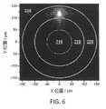
2.「ビーム径」(beam diameter)という用語は、放射照度(強度)が最大放射照度の1/e2に等しい軸に沿ったビームの中心を横切る距離として定義される。本明細書において開示する例は、一般に、方位角方向対称モードで伝搬するビームを使用するが、楕円形または他のビーム形状も使用することができ、ビーム径は異なる軸に沿って異なることもあり得る。円形ビームは1つのビーム径によって特徴付けられる。他のビーム形状は、異なる軸に沿って異なるビーム径を有する可能性がある。2. The term "beam diameter" is defined as the distance across the center of the beam along the axis where the irradiance (intensity) is equal to 1/e2 of maximum irradiance. Examples disclosed herein generally use beams propagating in azimuthally symmetric modes, but elliptical or other beam shapes can also be used, and beam diameters can vary along different axes. could be. A circular beam is characterized by one beam diameter. Other beam shapes may have different beam diameters along different axes.
3.「スポット・サイズ」(spot size)という用語は、最大放射強度の中心点から1/e2点までの半径方向距離(半径)である。3. The term "spot size" is the radial distance (radius) from the center point of maximum radiant intensity to the 1/e2 point.
4.「ビーム発散分布」(beam divergence distribution)という用語は、パワー対最大円錐角である。この量は、「角度分布」(angular distribution)または「NA分布」(NA distribution)と呼ばれることもある。 4. The term "beam divergence distribution" is power versus maximum cone angle. This quantity is sometimes called the "angular distribution" or the "NA distribution".
5.レーザ・ビームの「ビーム・パラメータ積」(beam parameter product)(BPP)という用語は、ビーム半径(ビームのくびれにおいて測定される)とビーム発散半角(遠場において測定される)との積として定義される。BPPの単位は通例mm-mradである。 5. The term "beam parameter product" (BPP) of a laser beam is defined as the product of the beam radius (measured at the beam waist) and the beam divergence half angle (measured at the far field). be done. The unit of BPP is typically mm-mrad.
6.「閉じ込めファイバ」(confinement fiber)は、1つ以上の閉じ込め領域を保有するファイバであると定義される。ここで、閉じ込め領域は、屈折率が低い方の領域(クラッディング領域)によって包囲された屈折率が高い方の領域(コア領域)を含む。閉じ込めファイバのRIPは、屈折率が低い方の領域(クラッディング領域)によって包囲された1つ以上の屈折率が高い方の領域(コア領域)を含んでもよく、光は屈折率が高い方の領域内において誘導される。各閉じ込め領域および各クラッディング領域は、ステップ・インデックス型(step-index) およびグレーデッド・インデックス型(graded-index)を含むがこれらに限定されない、任意のRIPを有することができる。閉じ込め領域は、同心円状であってもなくてもよく、更に円形、環状、多角形、弓状、楕円形、または不規則形状等、あるいはこれらの組み合わせのような種々の形状であってもよい。特定の閉じ込めファイバにおける閉じ込め領域は、全て同じ形状であってもよく、または異なる形状であってもよい。更に、閉じ込め領域は同軸状であってもよく、または互いに対してずれた軸を有してもよい。閉じ込め領域は、長手方向の中心軸を中心に均一の厚さでもよく、または厚さは長手方向の中心軸を中心に変化してもよい。 6. A "confinement fiber" is defined as a fiber that possesses one or more confinement regions. Here, the confinement region comprises a region of higher refractive index (the core region) surrounded by a region of lower refractive index (the cladding region). The RIP of the confinement fiber may include one or more higher index regions (core regions) surrounded by lower index regions (cladding regions), the light Induced within the area. Each confinement region and each cladding region can have any RIP, including but not limited to step-index and graded-index. The confinement regions may or may not be concentric, and may be of various shapes such as circular, annular, polygonal, arcuate, elliptical, or irregular, etc., or combinations thereof. . The confinement regions in a particular confinement fiber may all be of the same shape or may be of different shapes. Further, the confinement regions may be coaxial or may have axes offset with respect to each other. The confinement region may have a uniform thickness about the central longitudinal axis, or the thickness may vary about the central longitudinal axis.
7.「強度分布」(intensity distribution)という用語は、線分(1Dプロファイル)に沿った位置または平面(2Dプロファイル)上における位置の関数としての光強度を指す。線分または平面は、光の伝搬方向に対して垂直に取られるのが普通である。これは定量的プロパティである。 7. The term "intensity distribution" refers to light intensity as a function of position along a line segment (1D profile) or on a plane (2D profile). Line segments or planes are usually taken perpendicular to the direction of light propagation. This is a quantitative property.
8.「輝度」(luminance)とは、所与の方向に進む光の単位面積当たりの光度の測光尺度である。 8. "Luminance" is a photometric measure of the luminous intensity per unit area of light traveling in a given direction.
9.「M2係数」(M2 factor)(「ビーム品質係数」または「ビーム伝搬係数」とも呼ぶ)は、レーザ・ビームのビーム品質を定量化するための、次元がないパラメータであり、M2=1の場合回折限界ビームであり、M2値が大きくなるに連れて低いビーム品質に対応する。M2はBPPをλ/πで除算した値に等しく、ここでλはミクロン単位のビームの波長である(BPPがmm-mrad単位で表される場合)。9. The "M2 factor" (also called "beam quality factor" or "beam propagation factor") isa dimensionless parameter for quantifying the beam quality of a laser beam, whereM2 = A value of 1 is a diffraction limited beam, with higherM2 values corresponding to poorer beam quality.M2 is equal to BPP divided by λ/π, where λ is the wavelength of the beam in microns (if BPP is expressed in mm-mrad).
10.光学系の「開口数」(numerical aperture)または「NA」という用語は、その系が光を受け入れるまたは発することができる角度の範囲を特徴付ける、次元のない数値である。 10. The term "numerical aperture" or "NA" of an optical system is a dimensionless number that characterizes the range of angles that the system can accept or emit light.
11.「光強度」(optical intensity)という用語は、正式な(SI)単位ではなく、表面上の単位面積当たりの入射パワーまたは平面を貫通する入射パワーを示すために使用される。 11. The term "optical intensity" is used to indicate incident power per unit area on a surface or through a plane, rather than in formal (SI) units.
12.「パワー密度」(power density)という用語は、単位面積当たりの光パワーを指すが、これは「光強度」(optical intensity)とも呼ばれる。 12. The term "power density" refers to optical power per unit area, also called "optical intensity".
13.「半径方向ビーム位置」(radial beam position)という用語は、ファイバ軸に対して垂直な方向におけるファイバ・コアの中心に関して測定されたファイバ内におけるビームの位置を指す。 13. The term "radial beam position" refers to the position of the beam within the fiber measured with respect to the center of the fiber core in a direction perpendicular to the fiber axis.
14.「放射輝度」(radiance)とは、光源(例えば、レーザ)の単位面積によって所与の方向に単位立体角当たり放出される放射光線(radiation)である。放射輝度は、ビーム強度分布および/またはビーム発散プロファイルもしくは分布を変化させることによって変更することができる。レーザ・ビームの放射輝度プロファイルを変化させる能力は、BPPを変化させる能力を暗示する。 14. "Radiance" is the radiation emitted per unit solid angle in a given direction by a unit area of a light source (eg, a laser). Radiance can be changed by changing the beam intensity distribution and/or the beam divergence profile or distribution. The ability to change the radiance profile of the laser beam implies the ability to change the BPP.
15.「屈折率分布」(refractive-index profile)または「RIP」は、ファイバ軸に対して垂直な線分(1D)に沿った位置、または平面(2D)における位置の関数とした屈折率を指す。多くのファイバは方位角方向に対称であり、この場合1D RIPはあらゆる方位角に対して同一となる。 15. "Refractive-index profile" or "RIP" refers to refractive index as a function of position along a line segment (1D) perpendicular to the fiber axis or in a plane (2D). Many fibers are azimuthally symmetric, in which case the 1D RIP will be the same for every azimuth.
16.「ステップ・インデックス・ファイバ」(step-index fiber)は、ファイバ・コア内では平坦なRIPを有する(位置に関係ない屈折率)。 16. A "step-index fiber" has a flat RIP in the fiber core (position-independent refractive index).
17.「グレーデッド・インデックス・ファイバ」(graded-index fiber)は、半径方向位置が増大するに連れて(即ち、ファイバ・コアの中心からの距離が増大するに連れて)屈折率が減少するRIPを有する。 17. A "graded-index fiber" is a RIP whose refractive index decreases with increasing radial position (i.e., increasing distance from the center of the fiber core). have.
18.「二乗分布型ファイバ」(parabolic-index fiber)は、グレーデッド・インデックス・ファイバの特異事例であり、ファイバ・コアの中心からの距離が増大するに連れて、屈折率が二次関数的に減少する。 18. A "parabolic-index fiber" is a special case of graded-index fiber in which the refractive index decreases quadratically with increasing distance from the center of the fiber core. do.
ビーム特性を変化させるためのファイバ
[0035] 本明細書において開示するのは、先に説明した従来の方法のコスト、複雑さ、光損失、またはその他の欠点を減らすことができ、可変ビーム特性(VBC)を有するレーザ・ビームを供給するように動作可能なファイバを提供するように構成された方法、システム、および機器である。このVBCファイバは、広範囲におよぶ多様な光ビーム特性を変化させるように構成される。このようなビーム特性は、VBCファイバを使用して制御することができ、つまり、ユーザが広く多様なレーザ処理用途の個々の要件に適するように、種々のビーム特性を調整する(tune)ことを可能にする。例えば、ビーム径、ビーム発散分布、BPP、強度分布、M2係数、NA、光強度、パワー密度、半径方向ビーム位置、放射輝度、スポット・サイズ等、またはこれらの任意の組み合わせを調整するために、VBCファイバを使用することができる。Fibers for changing beam characteristics
[0035] Disclosed herein is a laser beam with variable beam characteristics (VBC) that can reduce the cost, complexity, optical loss, or other drawbacks of the conventional methods previously described. Methods, systems, and apparatus configured to provide fiber operable to feed. This VBC fiber is configured to change a wide variety of light beam characteristics. Such beam properties can be controlled using VBC fibers, allowing the user to tune various beam properties to suit the individual requirements of a wide variety of laser processing applications. to enable. For example, to adjust beam diameter, beam divergence distribution, BPP, intensity distribution,M2 factor, NA, light intensity, power density, radial beam position, radiance, spot size, etc., or any combination thereof. , VBC fibers can be used.
[0036] 一般に、開示する技術は、レーザ・ビームをファイバ内に結合し、このファイバにおいて、種々の方法の内任意のもの(例えば、ファイバを折り曲げる、または1つ以上の他の摂動を導入する)によってレーザ・ビームに摂動を起こしおよび/または第1長のファイバに摂動を起こすことによってレーザ・ビームの特性を調節することができ、調節したビーム特性を完全にまたは部分的に第2長のファイバにおいて維持することを伴う。第2長のファイバは、調節したビーム特性を維持する、および/または更に修正するように特別に構成される。ある場合には、第2長のファイバは、レーザ・ビームのその最終的な使用(例えば、材料処理)への伝達の間中、調節したビーム特性を保存する。第1および第2長のファイバは、同じファイバまたは異なるファイバを含んでもよい。 [0036] In general, the disclosed technique couples a laser beam into a fiber and introduces one or more other perturbations in the fiber in any of a variety of ways (e.g., bending the fiber or introducing one or more other perturbations). ) and/or by perturbing the fiber of the first length to adjust the properties of the laser beam, the adjusted beam properties being fully or partially of the second length. It involves keeping in the fiber. The second length of fiber is specially configured to maintain and/or further modify the adjusted beam characteristics. In some cases, the second length of fiber preserves the adjusted beam properties throughout transmission of the laser beam to its ultimate use (eg, material processing). The first and second lengths of fiber may comprise the same fiber or different fibers.
[0037] 開示する技術は、レーザ・ファイバおよびファイバ結合レーザと適合する。ファイバ結合レーザは、通例、ステップ・インデックス型の屈折率分布(RIP)を有する伝送ファイバ、即ち、ファイバ・コア内の屈折率が平坦または一定である伝送ファイバを通じて出力を伝送する。実際には、伝送ファイバのRIPはファイバの設計によっては、完全に平坦ではない場合もある。重要なパラメータは、ファイバ・コア径(dcore)およびNAである。コア径は、通例、10~1000ミクロンの範囲内であり(しかし、他の値も可能である)、NAは、通例、0.06~0.22の範囲内である(しかし、他の値も可能であるx)。レーザからの伝送ファイバは、直接プロセス・ヘッドまたは作業片に導かれることもあり、あるいはファイバ間カプラ(FFC:fiber-to-fiber coupler)またはファイバ間スイッチ(FFS:fiber-to-fiber switch)に導かれることもあり、このカプラまたはスイッチが光を伝送ファイバからプロセス・ファイバに結合し、プロセス・ファイバがビームをプロセス・ヘッドまたは作業片に送信する。[0037] The disclosed technology is compatible with laser fibers and fiber-coupled lasers. Fiber-coupled lasers typically transmit output through a transmission fiber having a step index profile (RIP), ie, a transmission fiber with a flat or constant refractive index within the fiber core. In practice, the RIP of a transmission fiber may not be perfectly flat, depending on the fiber design. Important parameters are fiber core diameter (dcore ) and NA. The core diameter is typically in the range 10-1000 microns (although other values are possible) and the NA is typically in the range 0.06-0.22 (although other values are possible). x). The transmission fiber from the laser may be led directly to the process head or work piece, or to a fiber-to-fiber coupler (FFC) or fiber-to-fiber switch (FFS). This coupler or switch couples the light from the transmission fiber to the process fiber, which transmits the beam to the process head or work piece.
[0038] 殆どの材料処理ツール、特に、高パワー(>1kW)のものは、多モード(MM:multimode)ファイバを採用するが、一部は、dcoreおよびNA範囲の下端にある単一モード(SM)ファイバを採用する。SMファイバからのビーム特性は、ファイバ・パラメータによって一意に決定される。しかしながら、MMファイバからのビーム特性は、ファイバに結合されているレーザ源(1つまたは複数)からのビーム特性、ファイバへの発射(launching)または繋ぎ(splicing)条件、ファイバのRIP、ファイバの静的および動的外形(曲げ、渦巻き、動き、マイクロベンディング等)に応じて、変動する可能性がある(単位毎、および/またはレーザ・パワーや時間の関数として)。SMおよびMM双方の伝送ファイバについては、所与の材料処理作業にとってビーム特性が最適にならない場合があり、広範囲の作業にとって最適になることはありそうにないので、特定の処理作業に合わせてこれらをカスタム化するまたは最適化するために、系統的にビーム特性を変化させることを可能にしたいという要望が高まっている。[0038] Most material processing tools, especially those with high power (>1 kW), employ multimode (MM) fibers, although some are single mode at the lower end of the dcore and NA ranges. (SM) fiber is employed. Beam characteristics from SM fibers are uniquely determined by the fiber parameters. However, the beam characteristics from an MM fiber depend on the beam characteristics from the laser source(s) coupled to the fiber, the launching or splicing conditions into the fiber, the RIP of the fiber, the static of the fiber. It can vary (per unit and/or as a function of laser power and time) depending on the target and dynamic geometry (bending, swirling, motion, microbending, etc.). For both SM and MM transmission fibers, the beam characteristics may not be optimal for a given material processing task, and are unlikely to be optimal for a wide range of tasks, so these are tailored to specific processing tasks. There is a growing desire to be able to systematically vary the beam properties in order to customize or optimize the .
[0039] 一例では、VBCファイバは第1長および第2長を有することができ、ビーム特性の所望の調節可能性を提供するために、伝送ファイバとプロセス・ファイバとの間におけるファイバ内デバイスとして介在させるように構成することができる。ビームの調節を可能にするために、摂動デバイスおよび/またはアセンブリをVBCファイバに近接して配置し、および/またはVBCファイバと結合し、ビーム特性がファイバの第1長において変更されるように、第1長においてビームに摂動を起こす役割を果たし、変更された特性は、ビームが第2長のファイバ内を伝搬する間保存されるか、または更に変更される。摂動を起こされたビームは、調節されたビーム特性を保存するように構成された第2長のVBCファイバ内に発射される。第1および第2長のファイバは、同じファイバでも異なるファイバでもよく、および/または第2長のファイバは閉じ込めファイバを構成することができる。第2長のVBCファイバによって保存されたビーム特性は、ビーム径、ビーム発散分布、BPP、強度分布、輝度、M2係数、NA、光強度、パワー密度、半径方向ビーム位置、放射輝度、スポット・サイズ等、またはこれらの任意の組み合わせの内任意のものを含むことができる。[0039] In one example, the VBC fiber can have a first length and a second length, and as an in-fiber device between the transmission fiber and the process fiber to provide desired adjustability of the beam properties. It can be configured to intervene. disposing a perturbation device and/or assembly proximate to and/or coupling with the VBC fiber to enable tuning of the beam, such that the beam characteristics are altered in the first length of the fiber; The altered properties that serve to perturb the beam in the first length are preserved or further altered while the beam propagates in the second length of fiber. The perturbed beam is launched into a second length of VBC fiber configured to preserve the adjusted beam characteristics. The first and second lengths of fiber may be the same or different fibers, and/or the second length of fiber may constitute a confinement fiber. The beam properties preserved by the second length of VBC fiber are beam diameter, beam divergence distribution, BPP, intensity distribution, brightness,M2 factor, NA, light intensity, power density, radial beam position, radiance, spot size, etc., or any combination thereof.
[0040] 図1は、ビーム特性を変化させるために自由空間光学素子の使用を必要とせずに、可変ビーム特性を有するレーザ・ビームを提供するためのVBCファイバの例100を示す。VBCファイバ100は、第1長のファイバ104と第2長のファイバ108とを含む。第1長のファイバ104および第2長のファイバ108は、同じファイバでも異なるファイバでもよく、同じRIPまたは異なるRIPを有してもよい。第1長のファイバ104および第2長のファイバ108は、スプライスによって一緒に接合されてもよい。第1長のファイバ104および第2長のファイバ108は、他の方法で結合されてもよく、離間されてもよく、あるいは他の長さのファイバ、自由空間光学素子、糊、屈折率整合材(index-matching material)等、またはこれらの組み合わせのような、介在部品を介して接続されてもよい。 [0040] Figure 1 shows an
[0041] 摂動デバイス110が、摂動領域106に近接して配置される、および/または摂動領域106を包み込む。摂動デバイス110は、デバイス、アセンブリ、ファイバ内構造、および/またはその他の機構(feature)でもよい。摂動デバイス110は、少なくとも、光ビーム102の1つ以上のビーム特性を調節するために、第1長のファイバ104または第2長のファイバ108、あるいはその組み合わせにおいて、光ビーム102に摂動を起こす。摂動デバイス110による摂動に応答するビーム102の調節は、第1長のファイバ104または第2長のファイバ、あるいはその組み合わせにおいて行われてもよい。摂動領域106は、種々の幅にわたって広がってもよく、更に第2長のファイバ108の一部に及んでも及ばなくてもよい。ビーム102がVBCファイバ100内を伝搬すると、摂動デバイス110は、ファイバに摂動を起こしビーム102の特性を調節するように、VBCファイバ100に物理的に作用することができる。あるいは、摂動デバイス110は、ビーム102のビーム特性を変更するために、直接ビーム102に作用してもよい。調節された後、摂動を起こされたビーム112はビーム102とは異なるビーム特性を有し、このビーム特性は第2長のファイバ108において完全にまたは部分的に保存される。他の例では、摂動デバイス110をスプライスに近接して配置する必要はない。更に、スプライスが全く不要となる場合もある。例えば、VBCファイバ100が1本のファイバである場合、第1長のファイバおよび第2長のファイバを離間させることができる場合、または小さな間隙をもって固定される場合である(空気で離間される、あるいは光セメントまたは屈折率整合材のような光材料で満たされる)。 A
[0042] 摂動を起こされたビーム112は、第2長のファイバ108内に発射され、この中で、摂動を起こされたビーム112の特性はほぼ維持されるか、または摂動を起こされたビーム112が伝搬するに連れて発達し続け、第2長のファイバ108の出力において、調節されたビーム特性が得られる。一例では、新たなビーム特性は調節された強度分布を含むのでもよい。一例では、変更されたビーム強度分布は、第2長のファイバ108の種々の構造的に制限された閉じ込め領域内に保存される。つまり、ビーム強度分布は、特定のレーザ処理作業に合わせて最適化された所望のビーム強度分布に調整することができる。一般に、摂動ビーム112の強度分布は、それが第2長のファイバ108内を伝搬するに連れて発達し、第1長のファイバ104内における条件および摂動デバイス110によって起こされた摂動に応答して、 摂動を起こされたビーム112が入射する閉じ込め領域(1つまたは複数)を満たす。加えて、ビームが第2ファイバ内を伝搬するに連れて、発射条件およびファイバ特性に応じて角度分布も発達することがある。一般に、ファイバは、入力発散分布をほぼ保存するが、入力発散分布が狭い場合、および/またはファイバが不規則性を有するもしくは発散分布に摂動を起こす意図的な構造を有する場合、この分布を広げることができる。種々の閉じ込め領域、摂動、および第2長のファイバ108のファイバ構造(fiber feature)については、以下で更に詳しく説明する。ビーム102および112は、可変ビーム特性を提供するために、ビームがどのようにVBCファイバ100を伝搬するとよいか例示することを意図した概念的な抽象化であり、特定の光ビームの挙動を詳しくモデル化することを意図するのではない。 [0042] The
[0043] VBCファイバ100は、PCVD(プラズマ化学蒸着)、OVD(外部蒸着)、VAD(気相軸付け法)、MOCVD(金属有機化学蒸着)、および/またはDND(直接ナノ粒子堆積)を含む種々の方法によって製造することができる。VBCファイバ100は、種々の材料を含むことができる。例えば、VBCファイバ100は、SiO2、GeO2がドープされたSiO2、ゲルマノシリケート、五酸化りん、ホスホシリケート、Al2O3、アルミノケイ酸塩等、またはこれらの任意の組み合わせを含んでもよい。閉じ込め領域は、フッ素、硼素等またはその任意の組み合わせがドープされたクラッディングによって囲まれるとよい。アクティブ・ファイバには他のドーパントが添加されてもよく、Er3+(エルビウム)、Yb3+(イッテルビウム)、Nd3+(ネオジウム)、Tm3+(ツリウム)、Ho3+(ホルミウム)等、またはこれらの任意の組み合わせのような希土類イオンを含む。閉じ込め領域は、フッ素または硼素のドーピングによって、閉じ込め領域よりも低い屈折率を有するクラッディングによって囲まれるとよい。あるいは、VBCファイバ100はフォトニツク結晶ファイバまたは微細構造ファイバを含んでもよい。[0043] The
[0044] VBCファイバ100は、種々のファイバ、光ファイバ、またはファイバ・レーザ・デバイスの内任意のものにおける使用に適しており、連続波およびパルス状ファイバ・レーザ、ディスク・レーザ、固体レーザ、またはダイオード・レーザ(物理的制約による以外には、パルス・レートは制限を受けない)を含む。更に、単にファイバだけでなく、平面導波路または他の種類の導波路における実装も、特許請求する技術の範囲内に該当する。 [0044]
[0045] 図2は、光ビームのビーム特性を調節するためのVBCファイバの例200の断面図を示す。一例では、VBCファイバ200はプロセス・ファイバとしてもよい。何故なら、これは材料処理のためにビームをプロセス・ヘッドに伝送することができるからである。VBCファイバ200は、接合部206において第2長のファイバ208に繋がれた第1長のファイバ204を含む。摂動アセンブリ210が、接合部206に近接して配置される。摂動アセンブリ210は、VBCファイバ200内を伝搬する光ビーム202のビーム特性の調節を可能にするように構成された種々のデバイスの内任意のものでよい。一例では、摂動アセンブリ210は、スプライス付近においてVBCファイバ200の曲げ半径および/または曲げ長を変化させる手段を提供することができるマンドレル(mandrel)および/または他のデバイスでもよい。摂動デバイスの他の例について、図24に関して以下で論ずる。 [0045] Figure 2 shows a cross-sectional view of an
[0046] 一例では、第1長のファイバ204は、左側のRIPグラフによって示されるように、二乗分布型屈折率RIP212を有する。ビーム202の強度分布の殆どは、ファイバ204が直線状またはほぼ直線状であるときは、ファイバ204の中央に集中する。第2長のファイバ208は、右側のRIPグラフに示すようなRIP214を有する閉じ込めファイバである。第2長のファイバ208は、閉じ込め領域216、218、および220を含む。閉じ込め領域216は、2つの環状(またはリング形状)閉じ込め領域218および220によって囲まれた中央コアである。層222および224は、閉じ込め領域(216、218、および220)間における、屈折率がもっと低い材料の構造的バリアであり、一般に「クラッディング」領域と呼ばれる。一例では、層222および224は、フルオロケイ酸塩のリングを構成してもよく、ある実施形態では、フルオロケイ酸塩のクラッディング層は比較的薄い。他の材料も同様に使用することができ、特許請求する主題がこれに関して限定されることはない。 [0046] In one example, the first length of
[0047] 一例では、ビーム202がVBCファイバ200に沿って伝搬すると、摂動アセンブリ210が物理的にファイバ208および/またはビーム202に作用して、そのビーム特性を調節し、調節されたビーム226を生成することができる。この例では、ビーム202の強度分布が摂動アセンブリ210によって修正される。ビーム202の調節後では、調節されたビーム226の強度分布は、外側の閉じ込め領域218および220に集中することができ、中央の閉じ込め領域216では比較的小さい強度となる。閉じ込め領域216、218、および/または220の各々はバリア層222および224において屈折率がもっと低い材料の薄い層によって分離されるので、第2長のファイバ208は、調節されたビーム226の調節された強度分布を実質的に維持することができる。ビームは、通例、所与の閉じ込め領域内で方位角方向に分散される(distribute)が、第2長のファイバ208に沿って伝搬する際に、閉じ込め領域間で(著しく)移行することはない。つまり、調節されたビーム226の調節されたビーム特性は、分離された閉じ込め領域216、218、および/または220内においてほぼ保存される。ある場合には、ビーム226のパワーが1つの領域に集中するのではなく、閉じ込め領域216、218、および/または220間で分割されることが望ましいこともあり、この条件は、しかるべく調節されたビーム226を生成することによって達成することができる。 [0047] In one example, as the
[0048] 一例では、コア閉じ込め領域216ならびに環状閉じ込め領域218および220は、溶融シリカ・ガラスで構成されてもよく、閉じ込め領域を定めるクラッディング222および224は、フルオロケイ酸塩ガラスで構成されてもよい。種々の閉じ込め領域(216、218、および220)を形成するためには、他の材料を使用してもよく、ゲルマノケイ酸塩、りんケイ酸塩、アルミノケイ酸塩等、またはこれらの組み合わせを含み、特許請求する主題がそれに限定されることはない。バリア・リング(222および224)を形成するには、溶融シリカ、ホウケイ酸等、またはこれらの組み合わせを含む他の材料を使用してもよく、特許請求する主題がそれらに限定されることはない。他の実施形態では、光ファイバまたは導波路は、種々のポリマー、またはプラスチック、または結晶材料を含む、またはこれらによって構成される。一般に、コア閉じ込め領域の屈折率は、隣接するバリア/クラッディング領域の屈折率よりも大きい。 [0048] In one example,
[0049] ある例では、ビーム・プロファイルを微調整するために、第2長のファイバにおける閉じ込め領域の数を増やして、ビーム変位に対するビーム制御の粒度を高めることが望ましい場合もある。例えば、閉じ込め領域は、段階的なビーム変位が得られるように構成されてもよい。 [0049] In some instances, it may be desirable to increase the number of confinement regions in the second length of fiber to provide finer granularity of beam control to beam displacement in order to fine-tune the beam profile. For example, the confinement region may be configured to provide stepped beam displacement.
[0050] 図3は、光ビームの可変ビーム特性を提供するためにファイバ200に摂動を起こす方法の例を示す。ファイバの曲げ半径を変化させると、ファイバ内におけるビームの半径方向ビーム位置、発散角、および/または放射輝度プロファイルを変化させることができる。VBCファイバ200の曲げ半径は、ステップ型マンドレル(stepped mandrel)またはコアを摂動アセンブリ210として使用することによって、スプライス接合部206を中心として、第1曲げ半径R1から第2曲げ半径R2に減少させることができる。加えてまたは代わりに、マンドレル(1つまたは複数)またはコアの係合長も変化させることができる。VBCファイバ200を摂動アセンブリ210に係合させるために、ローラ250を採用してもよい。一例では、ローラ250のファイバ200との係合量は、固定のマンドレル半径を用いて、強度プロファイルの分布をファイバ200の外側の閉じ込め領域218および220に移すように示されている。ファイバ200の曲げ半径を変化させるには、クランプ・アセンブリ(clamping assembly)、フレキシブル・チューブ(flexible tubing)等、またはその組み合わせを使用するというように、種々の他の方法があり、特許請求する主題がこれに関して限定されることはない。他の例では、特定の曲げ半径に対して、VBCファイバ200が曲げられる長さも、制御され再現可能な方法で、ビーム特性を変化させることができる。例では、曲げ半径、および/または特定の曲げ半径においてファイバが曲げられる長さを変化させることによっても、1つ以上のモードをファイバ・コアの中心から半径方向に移すことができるように、ビームの強度分布を修正する。[0050] Figure 3 illustrates an example of a method of perturbing a
[0051] 接合部206を跨ぐファイバの曲げ半径を維持することによって、光ビーム202の半径方向ビーム位置および放射輝度プロファイルのような調節されたビーム特性が、第2長のファイバ208に発射される前に、ビーム202の非摂動状態に戻らないことを確保する。更に、調節されたビーム226の位置、発散角、および/または強度分布を含む、調節された半径方向ビーム特性を、VBCファイバ200曲げ半径の減少度合いおよび/または曲げ長の度合いに基づいて変化させることができる。このように、この方法を使用すると、特定のビーム特性を得ることができる。 [0051] By maintaining the bend radius of the fiber across the
[0052] この例では、第1RIP212を有する第1長のファイバ204は、接合部206において、第2RIP214を有する第2長のファイバ208に繋がれる。しかしながら、ビーム202のビーム特性の摂動を可能にする(例えば、マイクロベンディングによって)、更に調節されたビームの保存を可能にするように形成された1つのRIPを有する1本のファイバを使用することは可能である。このようなRIPは、図17、図18、および/または図19に例示されるファイバにRIPと同様であってもよい。 [0052] In this example, a first length of
[0053] 図7~図10は、VBCファイバ200(図2および図3において示した)に対する実験結果を示し、更に、摂動アセンブリ210がVBCファイバ200に作用してファイバを曲げたときの、VBCファイバ200の摂動に対するビーム応答も示す。図4~図6はシミュレーションであり、図7~図10は、SM1050nm光源からのビームが、40ミクロンのコア径を有する入力ファイバ(図示せず)に発射されたときの実験結果である。入力ファイバは、第2長のファイバ204に繋がれている。 [0053] Figures 7-10 show experimental results for the VBC fiber 200 (shown in Figures 2 and 3) and also show the
[0054] 図4は、異なるファイバ曲げ半径402に対する第1長のファイバ204について計算された最低次モード(LP01)のプロファイルを示すグラフの例400であり、ここでは、摂動アセンブリ210はVBCファイバ200を曲げることを伴う。ファイバの曲げ半径が減少するに連れて、VBCファイバ200のコアの中心404(r=0ミクロン)からコア/クラッディング界面(この例ではr=100ミクロンに位置する)に向けて遠ざかるように、モードが半径方向に移るように、VBCファイバ200内を伝搬する光ビームが調節される。これよりも高次のモード(LPin)も、曲げによって移る。つまり、直線状またはほぼ直線状のファイバ(曲げ半径が非常に大きい)では、LP01の曲線406は、VBCファイバ200の中心または中心付近を中心とする。約6cmの曲げ半径では、LP01の曲線408は、VBCファイバ200の中心406から約40μmの半径方向位置に移される。約5cmの曲げ半径では、LP01の曲線410は、VBCファイバ200の中心406から約50μmの半径方向位置に移される。約4cmの曲げ半径では、LP01の曲線412は、VBCファイバ200の中心406から約60μmの半径方向位置に移される。約3cmの曲げ半径では、LP01の曲線414は、VBCファイバ200の中心406から約80μmの半径方向位置に移される。約2.5cmの曲げ半径では、LP01の曲線416は、VBCファイバ200の中心406から約85μmの半径方向位置に移される。尚、このモードの形状は比較的一定のままであり(コアのエッジに近づくまで)、これは二乗分布型RIPの特異なプロパティであることを注記しておく。このプロパティは、ある状況では望ましい場合もあるが、VBC機能のために必須であるのではなく、他のRIPが採用されてもよい。[0054] FIG. 4 is an
[0055] 一例では、VBCファイバ200を真っ直ぐにした場合、LP01モードは、ファイバの中心に戻るように移る。つまり、第2長のファイバ208の目的は、ビームの調節された強度分布を、VBCファイバ200の中心から変位したた閉じ込め領域に「捕獲する」または閉じ込めることである。ファイバ204および208間のスプライスは、曲げ領域に含まれ、このために、移されたモード・プロファイルは、リング形状の閉じ込め領域218および220の一方に優先的に発射され、そうでなければ閉じ込め領域間で分散されることになる。図5および図6はこの効果を示す。[0055] In one example, when the
[0056] 図5は、VBCファイバ200がほぼ直線状であるときの、第2長のファイバ208内の接合部206における二次元強度分布の例を示す。LP01およびLPinの大部分が、ファイバ208の閉じ込め領域216内にある。図6は、VBCファイバ200が、第2長のファイバ208の閉じ込め領域220(最も外側の閉じ込め領域)を優先的に励起するように選択された半径で曲げられたときの、第2長のファイバ208内の接合部206における二次元強度分布を示す。LP01およびLPinの大部分が、ファイバ208の閉じ込め領域220内にある。[0056] Figure 5 shows an example of the two-dimensional intensity distribution at the
[0057] 一例では、第2長のファイバ208の閉じ込め領域216の直径は100ミクロンであり、閉じ込め領域218は、直径が120ミクロンと200ミクロンとの間であり、閉じ込め領域220は、直径が220ミクロンと300ミクロンの間である。閉じ込め領域216、218、および220は、厚さ10μmのフルオロケイ酸塩のリングによって分離されており、これらの閉じ込め領域に対して0.22のNAが得られる。閉じ込め領域の内径および外径、閉じ込め領域を分離するリングの厚さ、閉じ込め領域に対するNA値、ならびに閉じ込め領域の数は、他のものも採用することができる。 [0057] In one example, the
[0058] 再度図5を参照して、先に記したパラメータを用いると、VBCファイバ200が直線状であるとき、パワーの約90%が中央の閉じ込め領域216内に収容され、パワーの約100%が閉じ込め領域216および218内に収容される。ここで図6を参照すると、第2リング閉じ込め領域220を優先的に励起するようにファイバ200を曲げると、パワーのほぼ75%が閉じ込め領域220内に収容され、パワーの95%超が閉じ込め領域218および220内に収容される。これらの計算には、LP01および2つのこれよりも高次のモードが含まれるが、これは2~4kWファイバ・レーザにおいては典型的である。[0058] Referring again to FIG. 5, with the parameters noted above, when
[0059] 図5および図6から、摂動アセンブリ210がファイバを曲げるためにVBCファイバ200に作用する場合、曲げ半径が、第1長のファイバ204のモード強度分布の第2長のファイバ208の異なる誘導閉じ込め領域(216、218、および220)との空間的重複を決定することは明らかである。つまり、曲げ半径を変化させると、第2長のファイバ208の出力において強度分布を変化させることができ、これによってビームの直径またはスポット・サイズを変化させ、こうしてその放射輝度およびBPP値も変化させることができる。このスポット・サイズの調節は、全ファイバ構造において遂行することができ、自由空間光学素子を伴わず、結果的に、先に論じた自由空間光学素子の欠点を低減または解消することができる。また、このような調節は、曲げ半径、曲げ長、ファイバ張力、温度、または以下で論ずるその他の摂動を変更する他の摂動アセンブリによって行うこともできる。 [0059] From FIGS. 5 and 6, when the
[0060] 典型的な材料処理システム(例えば、切断または溶接ツール)では、プロセス・ファイバの出力が、プロセス・ヘッドによって、作業片においてまたはその近くで撮像される。つまり、図5および図6に示したように強度分布を変化させると、プロセスを所望通りに調整および/または最適化するために、作業片におけるビーム・プロファイルの変更(variation)が可能になる。以上の計算を目的にするためにのみ、2つのファイバに対して特定的なRIPを想定したが、他のRIPも可能であり、特許請求する主題がこれに関して限定されないことはない。 [0060] In a typical material processing system (eg, a cutting or welding tool), the output of a process fiber is imaged at or near a work piece by a process head. That is, varying the intensity distribution as shown in FIGS. 5 and 6 allows variation of the beam profile at the work piece to tailor and/or optimize the process as desired. For the purposes of the above calculations only, a RIP specific to two fibers has been assumed, but other RIPs are possible and claimed subject matter is not limited in this respect.
[0061] 図7~図10は、図2に示したVBCファイバ200の種々の曲げ半径に対する、更に他の出力ビームを例示するために、実験結果(測定された強度分布)を示す。 [0061] FIGS. 7-10 show experimental results (measured intensity distributions) to illustrate further output beams for various bend radii of the
[0062] 図7において、VBCファイバ200が直線状であるとき、ビームはほぼ完全に閉じ込め領域216に閉じ込められる。曲げ半径が減少するに連れて、強度分布は大きな直径の方に移っていく(図8~図10)。図8は、VBCファイバ200の曲げ半径が、閉じ込め領域218に優先的に強度分布を移すように選択されたときの強度分布を示す。図9は、曲げ半径を更に減少させ、閉じ込め領域220および閉じ込め領域218に向かって外側に強度分布を移すように選択されたときの実験結果を示す。図10において、最も小さい曲げ半径のとき、ビームはほぼ「ドーナツ・モード」となり、強度の殆どが最も外側の閉じ込め領域220に入っている。 [0062] In FIG. 7, when the
[0063] スプライス接合部206の一方側からの閉じ込め領域の励起にも拘わらず、強度分布は、ビームがVBCファイバ200内を伝搬するときの閉じ込め領域内部のスクランブリング(scrambling)のために、方位角方向にほぼ対称になる。ビームは、伝搬するときに、方位角方向にスクランブルするのが通例であるが、このプロセスを促進するために、種々の構造または摂動(例えば、コイル)を含ませることができる。 [0063] Despite excitation of the confinement region from one side of the
[0064] 図7~図10に示した実験に使用されたファイバ・パラメータについて、複数の閉じ込め領域に何らかの強度が存在したので、特定の閉じ込め領域だけが排他的に励起されることはなかった。この特徴は、ビーム強度分布をより平坦化するまたは分散することによって材料処理用途に最適化し、有利に活用することができる。所与の閉じ込め領域の励起をもっと明確にしなければならない用途では、異なるファイバRIPを採用すれば、この特徴を活用することができる。 [0064] For the fiber parameters used in the experiments shown in Figures 7-10, there was some intensity in multiple confinement regions, so no particular confinement region was exclusively excited. This feature can be optimized and exploited for material processing applications by making the beam intensity distribution more flattened or dispersed. Applications that require more defined excitation of a given confinement region can take advantage of this feature by employing different fiber RIPs.
[0065] 図7~図10に示す結果は、この実験において使用された特定のファイバに関するのであり、詳細は実施の詳細によって様々に変化する。具体的には、出力ビームの空間プロファイルおよび発散分布、ならびにそれらの曲げ半径に対する依存度は、採用される特定のRIP、スプライス・パラメータ、および第1ファイバに発射されるレーザ源の特性に依存する。 [0065] The results shown in Figures 7-10 are for the specific fibers used in this experiment, and details will vary depending on implementation details. Specifically, the spatial profile and divergence distribution of the output beams and their dependence on bend radius depend on the particular RIP employed, the splice parameters, and the characteristics of the laser source launched into the first fiber. .
[0066] 図2に示したものとは異なるファイバ・パラメータも使用してもよく、特許請求する主題の範囲内に入ることに変わりはない。具体的には、異なる入力ビーム・プロファイルとの適合性を促進するため、そして異なる出力ビーム特性を可能にするために、異なるRIPならびにコア・サイズおよび形状を使用してもよい。第1長のファイバに対するRIPの例には、図2に示した二乗分布型の屈折率分布に加えて、他のグレーデッド・インデックス型分布、ステップ・インデックス、ペデスタル設計(pedestal design)(即ち、ファイバの中心からの距離が大きくなるに連れて累進的に屈折率が低くなるネスト状コア)、および屈折率値は同じであるが、中央コアおよび周囲のリングに対して種々のNA値を用いるネスト状コアによる設計が含まれる。第2長のファイバに対するRIPの例には、図2に示した分布に加えて、閉じ込め領域の数が異なる閉じ込めファイバ、非均一な閉じ込め領域の厚さ、閉じ込め領域を囲むリングの厚さに対する異なるおよび/または非均一な値、閉じ込め領域に対する異なるおよび/または非均一なNA値、RIPの高屈折率および低屈折率部分に対する異なる屈折率値、円形以外の閉じ込め領域(楕円形、長円形、多角形、正方形、矩形、またはこれらの組み合わせのような領域)、更に図26~図28に関して更に詳しく論ずるようなその他の設計が含まれる。更に、VBCファイバ200、および本明細書において説明するVBCファイバの他の例は、2本のファイバの使用に限定されるのではない。ある例では、実施態様が1本のファイバまたは2本よりも多いファイバの使用を含んでもよい。ある場合には、ファイバ(1本または複数本)は軸方向に均一でなくてもよい。例えば、これらは、ファイバ・ブラグ・グレーティングまたは長周期グレーティングを含むことができ、あるいは直径がファイバの長さに沿って変化することも可能である。加えて、ファイバは、方位角方向に対称である必要はなく、例えば、コア(1つまたは複数)が正方形または多角形の形状を有することも可能である。種々のファイバ・コーティング(バッファ)を採用してもよく、高屈折率または屈折率整合コーティング(ガラス-ポリマー界面において光を除去する(strip))、および低屈折率コーティング(ガラス-ポリマー界面において全内部反射によって光を誘導する)を含む。ある例では、VBCファイバ200上に複数のファイバ・コーティングを使用してもよい。 [0066] Different fiber parameters than those shown in Figure 2 may be used and still fall within the scope of claimed subject matter. Specifically, different RIPs and core sizes and shapes may be used to facilitate compatibility with different input beam profiles and to allow different output beam characteristics. Examples of RIPs for the first length of fiber include, in addition to the squared index profile shown in FIG. 2, other graded index profiles, step index, pedestal designs (i.e. Nested cores with progressively lower refractive index with increasing distance from the center of the fiber), and the same refractive index values, but using different NA values for the central core and surrounding rings Nested core designs are included. Examples of RIPs for the second length of fiber include, in addition to the distribution shown in FIG. and/or non-uniform values, different and/or non-uniform NA values for the confinement region, different refractive index values for the high and low index portions of the RIP, non-circular confinement regions (elliptical, oval, poly areas such as squares, squares, rectangles, or combinations thereof), as well as other designs as discussed in more detail with respect to FIGS. 26-28. Further,
[0067] 図11~図16は、第1長のファイバ内を伝搬する光ビームの摂動に応答して、VBCファイバにおけるビーム特性の調節を可能にするための、第1長のファイバの例の断面図を示す。第1長のファイバにおいて調節することができるビーム特性のいくつかの例には、ビーム径、ビーム発散分布、BPP、強度分布、輝度、M2係数、NA、光強度プロファイル、パワー密度プロファイル、半径方向ビーム位置、放射輝度、スポット・サイズ等、またはこれらの任意の組み合わせがある。図11~図16に示し以下で説明する第1長のファイバは、単なる例であり、VBCファイバ・アセンブリにおけるビーム特性の調節を可能にするために利用することができる種々の第1長のファイバの網羅的な列挙(recitation)を示すのではない。図11~図16に示す第1長のファイバに対する材料、適切なRIP、およびその他の変数の選択は、少なくとも、所望のビーム出力に依存する。多種多様なファイバ変数が考えられ、特許請求する主題の範囲内に入る。つまり、特許請求する主題がここで示される例によって限定されることはない。[0067] FIGS. 11-16 illustrate examples of a first length of fiber for enabling adjustment of beam characteristics in a VBC fiber in response to perturbations of a light beam propagating in the first length of fiber. A cross-sectional view is shown. Some examples of beam properties that can be adjusted in the first length of fiber include beam diameter, beam divergence distribution, BPP, intensity distribution, brightness,M2 factor, NA, light intensity profile, power density profile, radius Directional beam position, radiance, spot size, etc., or any combination thereof. The first lengths of fiber shown in FIGS. 11-16 and described below are merely examples, and the various first lengths of fiber that can be utilized to allow adjustment of the beam characteristics in the VBC fiber assembly. It does not provide an exhaustive recitation of . The selection of materials, appropriate RIPs, and other variables for the first length of fiber shown in FIGS. 11-16 depends at least on the desired beam power. A wide variety of fiber variables are contemplated and fall within the scope of claimed subject matter. That is, claimed subject matter is not limited by the examples presented herein.
[0068] 図11において、第1長のファイバ1100は、ステップ・インデックス型分布1102を含む。図12は、「ペデスタルRIP」(即ち、ステップ・インデックス領域と、これを取り囲むもっと大きなステップ・インデックスの領域とを含むコア)1202を含む第1長のファイバ1200を示す。図13は、多重ペデスタルRIP(multiple-pedestal RIP)1302を含む第1長のファイバ1300を示す。 [0068] In FIG. FIG. 12 shows a first length of
[0069] 図14Aは、ドープ減少領域(down-doped region)1404によって囲まれたグレーデッド・インデックス型分布1418を含む第1長のファイバ1400を示す。ファイバ1400に摂動が起こされると、ファイバ1400においてモードが半径方向の外側に移る(例えば、ファイバ1400の曲げの間)として差し支えない。グレーデッド・インデックス型分布1402は、モード形状の維持または圧縮をも促進するように設計することができる。この設計は、ファイバの外周(即ち、ファイバ軸から変位したファイバ・コアの部分)に集中するビーム強度分布を有するビームを生成するように、ファイバ1400内を伝搬するビームの調節を促進することができる。先に説明したように、調節されたビームが、閉じ込め領域を有する第2長のファイバ内に結合されると、調節されたビームの強度分布を最も外側の閉じ込め領域内に捕獲し、ドーナツ形状の強度分布を得ることができる。ビーム・スポットが狭い外側閉じ込め領域を有すると、特定の材料処理作用を可能にするのに有用となる場合もある。 [0069] FIG. 14A shows a first length of
[0070] 図14Bは、ファイバ1400と同様に、 ドープ減少領域1408によって囲まれたグレーデッド・インデックス型分布1414を含む第1長のファイバ1406を示す。しかしながら、ファイバ1406は、分布1412において見ることができるように、発散構造1410(低屈折率領域)を含む。発散構造1410は、周囲のコアよりも低い屈折率を有する材料のエリアである。ビームが第1長のファイバ1406に発射されると、発散構造1410からの屈折が、第1長のファイバ1406においてビーム発散を増大させる。増大する発散の量は、ビームの発散構造1410との空間的重複量、および発散構造1410とコア材料との間の屈折率の差の大きさに依存する。発散構造1410は、入力発散分布および所望の出力発散分布に応じて、種々の形状を有することができる。一例では、発散構造1410は、三角形またはグレーデッド・インデックス形状を有する。 [0070] FIG. 14B shows a first length of
[0071] 図15は、屈折率一定領域1504によって囲まれた二乗分布型屈折率の中央領域1502を含む第1長のファイバ1500を示し、屈折率一定領域1504は、それよりも屈折率が低い環状層1506によって囲まれている。低屈折率環帯1506は、ファイバ1500内を伝搬するビームを誘導するのを補助する。伝搬するビームが摂動を受けると、モードはファイバ1500において半径方向に外側に移る(例えば、ファイバ1500の曲げの間)。1つ以上のモードが半径方向の外側に移ると、二乗分布型屈折率領域1502はモード形状の保持を促進する。モードがRIP1510の屈折率一定領域に達すると、これらは低屈折率リング1506に衝突して(against)圧縮され、これによって、第2ファイバにおける最外側の閉じ込め領域の優先的励起が生ずる(図14に示す第1ファイバRIPと比較して)。一実施態様では、このファイバ設計は、中央のステップ・インデックス・コアおよび1つの環状コアを有する閉じ込めファイバと相性がよい。RIPの二乗分布型屈折率部分1502は、閉じ込めファイバの中央のステップ・インデックス・コアと重複する。屈折率一定部分1504は、閉じ込めファイバの環状コアと重複する。第1ファイバの屈折率一定部分1504は、曲げによって、環状コアとの重複部分にビームを移動させやすくすることを意図している。このファイバ設計は、閉じ込めファイバの他の設計とも相性がよい。 [0071] Figure 15 shows a first length of
[0072] 図16は、誘導領域1604、1606、1608、および1616と、これらを取り囲み、これらよりも屈折率が低い層1610、1612、および1614とを含む第1長のファイバ1600を示す。屈折率が低い方の層1610、1612、および1614は、ステップ型であり、更に一般的には、全てが同じ値を有していない。ステップ・インデックス層は、摂動アセンブリ210(図2参照)がファイバ1600に作用したときに、ビーム強度を特定の誘導領域(1604、1606、1608、および1616)に拘束する役割を果たすことができる。このように、ある範囲の摂動作用にわたって(ある範囲の曲げ半径、ある範囲の曲げ長、ある範囲のマイクロベンディング圧力、および/またはある範囲の音響光学信号にわたってというように) 調節されたビーム光が誘導領域に捕獲され、ビーム強度分布がファイバ1600においてもっと離れた半径方向位置に移される前に、一定の度合いの摂動許容度を考慮に入れるようにしてもよい。つまり、ビーム特性の変化は、階段状に制御することができる。誘導領域1604、1606、1608、および1616の半径方向の幅は、用途によって要求されてもよいように、所望のリング幅を達成するために調節することができる。また、誘導領域は、所望であれば、到達するビーム・プロファイルからより多くの断片の捕獲をし易くするために、もっと厚い半径方向幅を有することができる。領域1606はこのような設計の一例である。 [0072] Figure 16 shows a first length of
[0073] 図17~図21は、第2長のファイバ(例えば、ファイバ208)において、調節されたビーム特性の維持および/または閉じ込めを可能にするように構成されたファイバの例を示す。これらのファイバ設計を「リング形状閉じ込めファイバ」と呼ぶ。何故なら、これらは、中央コアと、これを取り囲む環状またはリンク形状コアとを含むからである。これらの設計は単なる例に過ぎず、ファイバ内における、調節されたビーム特性の維持および/または閉じ込めを可能にするために使用することができる種々のファイバRIPの網羅的な列挙ではない。つまり、特許請求する主題がここで示す例に限定されることはない。更に、図11~図16に関して先に説明した第1長のファイバはいずれも、図17~図21において説明する第2長のファイバのいずれとでも組み合わせることができる。 [0073] FIGS. 17-21 illustrate examples of fibers configured to enable maintenance and/or confinement of tailored beam characteristics in a second length of fiber (eg, fiber 208). These fiber designs are called "ring-shaped confinement fibers." This is because they include a central core and a surrounding annular or link-shaped core. These designs are merely examples and are not an exhaustive listing of the various fiber RIPs that can be used to enable maintenance and/or confinement of tailored beam properties within the fiber. Thus, claimed subject matter is not limited to the examples provided herein. Further, any of the first length fibers described above with respect to FIGS. 11-16 can be combined with any of the second length fibers described in FIGS. 17-21.
[0074] 図17は、VBCファイバ・アセンブリにおいて、調節されたビーム特性を維持するおよび/または閉じ込めるための第2長のファイバの一例の断面図を示す。摂動を受けたビームが第1長のファイバから第2長のファイバ1700に結合されると、第2長のファイバ1700は、第1長のファイバにおける摂動に応答して調節されたビーム特性の内少なくとも一部を、閉じ込め領域1704、1706、および/または1708の内1つ以上の中に維持することができる。ファイバ1700はRIP1702を有する。閉じ込め領域1704、1706、および/または1708の各々は、それよりも屈折率が低い層1710および/または1712によって取り囲まれている。この設計によって、第2長のファイバ1700が、調節されたビーム特性を維持することが可能になる。その結果、ファイバ1700によるビーム出力は、第1長のファイバにおいて修正されたままに、調節されたビームを受けて実質的に維持し、処理作業または他の用途に合わせてカスタム化することができる調節ビーム特性(adjusted beam characteristics)を、出力ビームに与える。 [0074] Figure 17 shows a cross-sectional view of an example of a second length of fiber for maintaining and/or confining tailored beam characteristics in a VBC fiber assembly. When the perturbed beam is coupled from the first length of fiber to the second length of
[0075] 同様に、図18は、VBCファイバ・アセンブリにおいて、第1長のファイバにおける摂動に応答して調節されたビーム特性を維持するおよび/または閉じ込めるための第2長のファイバの例1800の断面図を示す。ファイバ1800はRIP1802を有する。しかしながら、閉じ込め領域1808、1810、および/または1812は、閉じ込め領域1704、1706、および1708とは異なる厚さを有する。閉じ込め領域1808、1810、および/または1812の各々は、それよりも屈折率が低い層1804および/または1806によって取り囲まれている。閉じ込め領域(および/またはバリア領域)の厚さを変化させることにより、調節されたビームを閉じ込めるようとする特定の半径方向位置を選択することによって、閉じ込められた調節放射輝度プロファイルの個別調整(tailoring)または最適化を可能にする。 [0075] Similarly, FIG. 18 illustrates an example
[0076] 図19は、可変ビーム特性を提供するように構成されたVBCファイバ・アセンブリにおいて、調節されたビームを維持するおよび/または閉じ込めるための、RIP1902を有する第2長のファイバの例1900の断面図を示す。この例では、閉じ込め領域1904、1906、1908、および1910の数および厚さは、ファイバ1700および1800とは異なり、バリア層1912、1914、および1916も異なる厚さのものとなっている。更に、閉じ込め領域1904、1906、1908、および1910は異なる屈折率を有し、バリア層1912、1914、および1916も異なる屈折率を有する。この設計は、更に、ファイバ1900内部の特定の半径方向位置への調節されたビーム放射輝度の閉じ込めおよび/または維持の一層粒度の高いあるいは最適化された個別調整を可能にするとして差し支えない。摂動を起こされたビームが第1長のファイバから第2長のファイバ1900に発射されると、ビームの修正されたビーム特性(調節された強度分布、半径方向位置、および/または発散角等、あるいはこれらの組み合わせを有する)が第2長のファイバ1900の閉じ込め領域1904、1906、1908、および/または1910の内1つ以上によって、特定の半径に閉じ込められる。 [0076] FIG. 19 illustrates an example
[0077] 先に注記したように、ビームの発散角が保存されてもよく、または調節され次いで第2長のファイバにおいて保存されてもよい。ビームの発散角を変化させるには種々の方法がある。以下にあげるのは、ビーム特性を変化させるためのファイバ・アセンブリにおいて、第1長のファイバから第2長のファイバに伝搬するビームの発散角の調節を可能にするように構成されたファイバの例である。しかしながら、これらは単なる例に過ぎず、ビーム発散の調節を可能にするために使用することができる種々の方法の網羅的な列挙ではない。つまり、特許請求する主題がここで示される例に限定されることはない。 [0077] As noted above, the divergence angle of the beam may be stored, or adjusted and then stored in the second length of fiber. There are various ways to change the divergence angle of the beam. The following are examples of fibers configured to allow adjustment of the angle of divergence of a beam propagating from a first length of fiber to a second length of fiber in a fiber assembly for varying beam characteristics. is. However, these are merely examples and are not an exhaustive listing of the various methods that can be used to allow beam divergence adjustment. Thus, claimed subject matter is not limited to the examples presented herein.
[0078] 図20は、第1長のファイバにおける摂動に応答して調節されたビーム特性を修正する、維持する、および/または閉じ込めるための、RIP2002を有する第2長のファイバの例の断面図を示す。この例では、第2長のファイバ2000は、以前に説明した第2長のファイバと同様であり、先に論じたように可変ビーム特性を伝えるためのVBCファイバ・アセンブリの一部を形成する。3つの閉じ込め領域2004、2006、および2008、ならびに3つのバリア層2010、2012、および2016がある。また、第2長のファイバ2000は、閉じ込め領域2006内に位置する発散構造2014も有する。発散構造2014は、周りの閉じ込め領域よりも低い屈折率を有する材料のエリアである。ビームが第2長のファイバ2000に発射されると、発散構造2014からの屈折が、第2長のファイバ2000においてビーム発散を増大させる。増大する発散の量は、ビームと発散構造2014との空間的重複量、および発散構造2014とコア材料との間の屈折率の差の大きさに依存する。第2長のファイバ2000への発射点付近においてビームの半径方向位置を調節することによって、発散分布を変化させることができる。ビームの調節された発散は、ファイバ2000内に保存される。ファイバ2000は、調節されたビームをプロセス・ヘッド、他の光学系(例えば、ファイバ間カプラまたはファイバ間スイッチ)、作業片等、またはこれらの組み合わせに伝送するように構成される。一例では、発散構造2014は、周りの材料に関して約10-5~3×10-2の屈折率の低下(dip)を有するとよい。屈折率低下の他の値も、本開示の範囲内で採用することもでき、特許請求する主題がそのように限定されることはない。[0078] FIG. 20 is a cross-sectional view of an example second length of fiber having a
[0079] 図21は、第1長のファイバにおける摂動に応答して調節されたビーム特性を修正する、維持する、および/または閉じ込めるための、RIP2102を有する第2長のファイバの例2100の断面図を示す。第2長のファイバ2100は、可変特性を有するビームを伝送するためのVBCファイバ・アセンブリの一部を形成する。この例では、3つの閉じ込め領域2104,2106、および2018、ならびに3つのバリア層2110、2112、および2116がある。また、第2長のファイバ2100は、複数の発散構造2114および2118も有する。発散構造2114および2118は、傾斜状に屈折率が低くなる材料のエリアである。ビームが第1長のファイバから第2長のファイバ2100に発射されると、発散構造2114および2118からの屈折が、ビーム発散を増大させる。増大する発散の量は、ビームと発散構造との空間的重複の量、ならびに、発散構造2114および/または2118とそれぞれの閉じ込め領域2106および2104の周りのコア材料との間の屈折率の差の大きさに依存する。第2長のファイバ2100への発射点付近においてビームの半径方向位置を調節することによって、発散分布を変化させることができる。図21に示す設計は、特定の閉じ込め領域と、この閉じ込め領域内における発散分布との双方を選択することによって、強度分布および発散分布をいくらか独立して変化させることを可能にする(各閉じ込め領域が発散構造を含んでもよいためである)。ビームの調節された発散は、ファイバ2100内に保存される。ファイバ2100は、調節されたビームをプロセス・ヘッド、他の光学系、または作業片に伝送するように構成される。発散構造2114および2118をグレーデッド・インデックス、即ち、一定でない屈折率によって形成することにより、ファイバ2100内を伝搬するビームの発散プロファイルの調整が可能になる。放射輝度プロファイルおよび/または発散プロファイルのような、調節されたビーム特性は、これが第2ファイバによってプロセス・ヘッドに伝送されるときに、保存することができる。あるいは、放射輝度プロファイルおよび/または発散プロファイルのような調節されたビーム特性は、これが第2ファイバによってファイバ間カプラ(FFC)および/またはファイバ間スイッチ(FFC)を介して、ビームをプロセス・ヘッドまたは作業片に伝送するプロセス・ファイバに導かれるときに、保存する、または更に調節することもできる。 [0079] FIG. 21 is a cross-section of an example
[0080] 図26~図28は、方位角方向に非対称的な第2長のファイバ内を伝搬するビームの調節されたビーム特性の維持および/または閉じ込めを可能にするように構成されたファイバおよびファイバRIPの例を示す断面図であり、ビーム特性は、第2長のファイバに結合された第1長のファイバの摂動、および/または摂動デバイス110によるビームの摂動に応答して調節される。これらの方位角方向に非対称的な設計は、単なる例に過ぎず、方位角方向に非対称的なファイバ内における、調節されたビーム特性の維持および/または閉じ込めを可能にするために使用することができる種々のRIPの網羅的な列挙ではない。つまり、特許請求する主題がここで示す例に限定されることはない。更に、種々の第1長のファイバ(例えば、先に説明したもののようなファイバ)の内任意のものが、任意の方位角方向に非対称的な第2長のファイバ(例えば、図26~図28において説明するもののようなファイバ)と組み合わされてもよい。 [0080] FIGS. 26-28 illustrate fibers and fibers configured to enable maintenance and/or confinement of adjusted beam characteristics of a beam propagating in a second length of fiber that is azimuthally asymmetric. 1 is a cross-sectional view of an example fiber RIP, the beam properties of which are adjusted in response to perturbations of a first length of fiber coupled to a second length of fiber and/or perturbations of the beam by
[0081] 図26は、楕円状ファイバ2600を通る断面の種々の方位角におけるRIPを示す。第1方位角2602において、ファイバ2600は第1RIP2604を有する。第1方位角2602から45°回転した第2方位角2606において、ファイバ2600は第2RIP2608を有する。第2方位角2606から更に45°回転した第3方位角2610において、ファイバ2600は第3RIP2612を有する。第1、第2、および第3RIP2604、2608、および2612は全て異なる。 [0081] FIG. 26 shows the RIP at various azimuthal angles of a cross-section through an
[0082] 図27は、多重コア・ファイバ2700を通る断面の種々の方位角におけるRIPを示す。第1方位角2702において、ファイバ2700は第1RIP2704を有する。第2方位角2706において、ファイバ2700は第2RIP2708を有する。第1および第2RIP2704および2708は異なる。一例では、摂動デバイス110は、調節されたビームを、方位角方向に非対称的な第2ファイバの異なる領域に発射するために複数の平面において作用することができる。 [0082] FIG. 27 shows the RIP at various azimuthal angles of a cross-section through
[0083] 図28は、少なくとも1つの三日月形状のコアを有するファイバ2800を通る断面の種々の方位角におけるRIPを示す。ある場合には、三日月の角部を丸めても、平坦にしても、またはそれ以外の形状にしてもよく、こうすることによって光損失を最小限に抑えることができる。第1方位角2802において、ファイバ2800は第1RIP2804を有する。第2方位角2806において、ファイバ2800は第2RIP2808を有する。第1および第2RIP2804および2808は異なる。 [0083] Figure 28 shows the RIP at various azimuthal angles of a cross-section through a
[0084] 図22Aは、可変ビーム特性を提供するように構成されたVBCファイバ・アセンブリ2202を含むレーザ・システムの例2200を示す。VBCファイバ・アセンブリ2202は、第1長のファイバ104、第2長のファイバ108、および摂動デバイス110を含む。VBCファイバ・アセンブリ2202は、供給ファイバ2212(即ち、レーザ源からの出力ファイバ)とVBC伝送ファイバ2240との間に配置される。VBC伝送ファイバ2240は、調節されたビーム特性を修正する、維持する、および/または閉じ込める、第2長のファイバ108または第2長のファイバ108の延長部を含んでもよい。ビーム2210は、供給ファイバ2212を通じて、VBCファイバ・アセンブリ2202に結合される。ファイバ・アセンブリ2202は、以上で説明した種々の例にしたがって、ビーム2210の特性を変化させるように構成される。ファイバ・アセンブリ2202の出力は、調節されたビーム2214であり、VBC伝送ファイバ2240に結合される。VBC伝送ファイバ2240は、調節されたビーム2214を自由空間光学素子アセンブリ2208に伝送し、次いで、自由空間光学素子アセンブリ2208はビーム2214をプロセス・ファイバ2204に結合する。次いで、調節されたビーム2214は、プロセス・ファイバ2204によって、プロセス・ヘッド2206に伝送される。プロセス・ヘッドは、導波路光学素子(ファイバおよびファイバ・カプラのような素子)、レンズ、ミラー、光学フィルタ、回折格子のような自由空間光学素子、検流計スキャナ、ポリゴン・ミラー・スキャナ、またはビーム2214を整形し整形したビームを作業片に伝送するために使用される他のスキャン・システムのようなビーム・スキャン・アセンブリを含むことができる。 [0084] Figure 22A shows an
[0085] レーザ・システム2200では、調節されたビーム2214の種々の光学的操作(図22Aにおいてビーム2210とは異なる点線(dashing)で表される)を実行するために、アセンブリ2208の自由空間光学素子の内1つ以上がFFCまたは他のビーム・カプラ2216内に配置されてもよい。例えば、自由空間光学素子アセンブリ2208は、ビーム2214の調節されたビーム特性を保存することもできる。プロセス・ファイバ2204は、VBC伝送ファイバ2240と同じRIPを有してもよい。つまり、調節されたビーム2214の調節されたビーム特性は、プロセス・ヘッド2206に至る経路の全てで保存することができる。プロセス・ファイバ2204は、閉じ込め領域を含む前述の第2長のファイバの内任意のものと同様のRIPを含んでもよい。 [0085] In
[0086] あるいは、図22Bに示すように、自由空間光学素子アセンブリ2208は、例えば、ビーム2214の発散および/またはスポット・サイズを増大あるいは減少させることによって(例えば、ビーム2214を拡大または縮小することによって)、および/またはそれ以外で更に調節されたビーム2214を修正することによって、ビーム2214の調節されたビーム特性を変化させることもできる。更に、プロセス・ファイバ2204は、VBC伝送ファイバ2240とは異なるRIPを有してもよい。したがって、プロセス・ファイバ2204のRIPは、2回調節されたビーム2224(図22Bにおいてビーム2214とは異なる点線で表される)を生成するために、アセンブリ2208の自由空間光学素子によって行われる、調節されたビーム2214の追加の調節を保存するように選択されてもよい。 Alternatively, as shown in FIG. 22B, free-
[0087] 図23は、供給ファイバ2312とVBC伝送ファイバ2340との間に配置されたVBCファイバ・アセンブリ2302を含むレーザ・システムの例2300を示す。動作中、ビーム2310は、供給ファイバ2312を通じて、VBCファイバ・アセンブリ2302に結合される。ファイバ・アセンブリ2302は、第1長のファイバ104、第2長のファイバ108、および摂動デバイス110を含み、以上で説明した種々の例にしたがってビーム2310の特性を変化させるように構成される。ファイバ・アセンブリ2302は、調節されたビーム2314を生成し、VBC伝送ファイバ2340によって出力する。VBC伝送ファイバ2340は、以上で説明した種々の例にしたがって(例えば、図17~図21参照)ファイバ・アセンブリ2302において、調節されたビーム特性を修正する、維持する、および/または閉じ込めるために第2長のファイバ108を含む。VBC伝送ファイバ2340は、調節されたビーム2314をビーム・スイッチ(FFS)2332に結合し、次いで、ビーム・スイッチ2332はその種々の出力ビームを、複数のプロセス・ファイバ2304、2320、および2322の内1つ以上に結合する。プロセス・ファイバ2304、2320、および2322は、調節されたビーム2314、2328、および2330を、それぞれのプロセス・ヘッド2306、2324、および2326に伝送する。 [0087] FIG. 23 illustrates an
[0088] 一例では、ビーム・スイッチ2332は、調節されたビーム2314の種々の光学的操作を実行するように構成された1組以上の自由空間光学素子2308、2316、および2318を含む。自由空間光学素子2308、2316、および2318は、ビーム2314の調節されたビーム特性を保存するまたは変化させることができる。つまり、調節されたビーム2314は、自由空間光学素子によって維持される、または更に調節されることが可能である。プロセス・ファイバ2304、2320、および2322は、自由空間光学素子アセンブリ2308、2316、および2318からそれぞれのプロセス・ファイバ2304、2320、および2322に進むビームを保存することまたは更に修正することが望ましいか否かに応じて、VBC伝送ファイバ2340と同じRIPまたは異なるRIPを有することができる。他の例では、ビーム2310の1つ以上のビーム部分が、調節されずに、作業片に結合されるか、または複数のビーム特性に関連付けられたビーム部分が同時作業片処理のために供給できるように、異なるビーム部分がそれぞれのVBCファイバ・アセンブリに結合される。あるいは、ビーム2310を1組のVBCファイバ・アセンブリの内1つ以上に切り替えることができる。 In one example,
[0089] 自由空間光学素子アセンブリ2208、2316、および2318の内任意のものを介して、調節されたビーム2314を導くことによって、種々の追加的に調節されたビームのプロセス・ヘッド2206、2324、および2326への伝送が可能になる。したがって、レーザ・システム2300は、ビームの特性を変化させる自由度を高め、更にプロセス・ヘッド間でビームを切り替える(「時分割」)、および/または複数のプロセス・ヘッドに同時にビームを伝送する(「パワー分割」)自由度も高める。 [0089] By directing the conditioned
[0090] 例えば、ビーム・スイッチ2332における自由空間光学素子は、ビーム2314の調節された特性を保存するように構成された自由空間光学素子アセンブリ2316に、調節されたビーム2314を方向付ける(direct)ことができる。プロセス・ファイバ2304は、VBC伝送ファイバ2340と同じRIPを有してもよい。つまり、プロセス・ヘッド2306に伝送されるビームは、調節され保存されたビーム2314となる。 [0090] For example, free-space optics in
[0091] 他の例では、ビーム・スイッチ2332が、調節されたビーム2314の調節された特性を保存するように構成された自由空間光学素子アセンブリ2318に、調節されたビーム2314を方向付けることもできる。プロセス・ファイバ2320は、VBC伝送ファイバ2340とは異なるRIPを有してもよく、ビーム2314の発散分布に対して追加の調節を行うために、図20および図21に関して説明したような、発散変更構造が装備されても(configured with)よい。つまり、プロセス・ヘッド2324に伝送されるビームは、調節されたビーム2314とは異なるビーム発散プロファイルを有する、2回調節されたビーム2328となる。 [0091] In another example,
[0092] プロセス・ファイバ2304、2320、および/または2322は、以上で説明した第2長のファイバの内任意のものと同様のRIPを含んでも良く、閉じ込め領域または多種多様な他のRIPを含み、特許請求する主題がこれに関して限定されることはない。 [0092]
[0093] 更に他の例では、自由空間光学素子アセンブリ2332が、調節されたビーム2314のビーム特性を変化させるように構成された自由空間光学素子アセンブリ2308に、調節されたビーム2314を方向付けるのでもよい。プロセス・ファイバ2322は、VBC伝送ファイバ2340とは異なるRIPを有してもよく、ビーム2314の新たに更に調節された特性を保存する(または、代わりに、更に修正する)ように構成されてもよい。つまり、プロセス・ヘッド2326に伝送されるビームは、調節されたビーム2314とは異なるビーム特性を有する(調節された発散プロファイルおよび/または強度プロファイルのために)2回調節されたビーム2330となる。 [0093] In yet another example, free-
[0094] 図22A、図22B、および図23では、FFCまたはFFSにおける光学素子は、ビーム2214がプロセス・ファイバ内に発射する前にビーム2214を拡大または縮小することによって、空間プロファイルおよび/または発散プロファイルを調節することができる。また、これらは、他の光学的変換(transformation)によって、空間プロファイルおよび/または発散プロファイルを調整することもできる。また、これらは、プロセス・ファイバへの発射位置を調節することもできる。これらの方法は、単独でも組み合わせても使用することができる。 [0094] In Figures 22A, 22B, and 23, the optical elements in the FFC or FFS adjust the spatial profile and/or divergence by expanding or contracting the
[0095] 図22A、図22B、および図23は、調節されたビーム2214および2314を保存または修正するために、自由空間光学素子およびファイバRIPの種々の組み合わせを使用する、ビーム特性に対する調節の組み合わせの例を示すに過ぎない。以上であげた例は、網羅的ではなく、例示を目的にするに過ぎないことを意味する。つまり、特許請求する主題がこれに関して限定されることはない。 [0095] Figures 22A, 22B, and 23 show combinations of adjustments to beam properties using various combinations of free-space optics and fiber RIPs to preserve or modify conditioned
[0096] 図24は、本明細書においてあげた種々の例にしたがって、VBCファイバ200、および/またはVBCファイバ200内を伝搬する光ビームに摂動を起こすための摂動デバイス、アセンブリ、または方法(簡単にするために、ここでは纏めて「摂動デバイス110」と呼ぶ)の種々の例を示す。摂動デバイス110は、VBCファイバ200内を伝搬するビームのビーム特性の調節を可能にするように構成された種々のデバイス、方法、および/またはアセンブリの内任意のものでよい。一例では、摂動デバイス110は、マンドレル2402、VBCファイバにおけるマイクロベンディング2404、フレキシブル・チュービング2406、音響光学変換器2408、熱デバイス(thermal device)2410,圧電デバイス2412、グレーティング2414、クランプ2416(または他の締結具)等、またはこれらの組み合わせでもよい。これらは、摂動デバイス100の例に過ぎず、摂動デバイス100の網羅的な列挙(listing)ではなく、特許請求する主題がこれに関して限定されることはない。 [0096] FIG. 24 illustrates a perturbation device, assembly, or method (simply Various examples of such devices, collectively referred to herein as "
[0097] マンドレル2402は、VBCファイバ200を曲げることができる形状を与えることによって、VBCファイバ200に摂動を起こすために使用することができる。先に論じたように、VBCファイバ200の曲げ半径を小さくすると、ビームの強度分布が半径方向の外側に動く。ある例では、マンドレル2402は、離散曲げ半径レベルを得るために、ステップ型にしてもまたは円錐形状にしてもよい。あるいは、マンドレル2402は、曲げ半径を更に粒度高く制御するための連続曲げ半径が得られるように、段のない円錐形状を含んでもよい。マンドレル2402の曲率半径は、一定(例えば、円筒形状)であっても、一定でなくても(例えば、長円形状)よい。同様に、フレキシブル・チュービング2406、クランプ2416(または他の様々な締結具)、またはローラ250も、マンドレル2402の周りでVBCファイバ200の曲げを誘導および制御するために使用することができる。更に、特定の曲げ半径においてファイバを曲げる長さを変更することによって、ビームの強度分布を修正することができる。VBCファイバ200およびマンドレル2402は、第1ファイバ内における強度分布を予測可能に変化させるように構成することができる(例えば、ファイバを曲げる長さおよび/または曲げ半径に比例する)。ローラ250は、VBCファイバ200の曲げ半径を変化させるために、プラットフォーム2434上のトラック2442に沿って往復運動する(move up and down)ことができる。 [0097] The
[0098] クランプ2416(または他の締結具)も、マンドレル2402を用いてまたは用いずに、VBCファイバ200の曲げを誘導および制御するために使用することができる。クランプ2416は、トラック2442またはプラットフォーム2446に沿って往復運動することができる。また、クランプ2416は、VBCファイバ200の曲げ半径、張力、または方向を変化させるために、旋回することもできる。コントローラ2448はクランプ2416の移動を制御することができる。 [0098] A clamp 2416 (or other fastener) can also be used to guide and control bending of the
[0099] 他の例では、摂動デバイス110は、フレキシブル・チュービング2406であってもよく、マンドレル2402を用いてまたは用いずに、VBCファイバ200の曲げを誘導することができる。フレキシブル・チュービング2406は、VBCファイバ200を包み込む(encase)ことができる。チュービング2406は、種々の材料で作ることができ、コントローラ2444によって制御される圧電変換器を使用して操作することができる。他の例では、クランプまたは他の締結具を使用して、フレキシブル・チュービング2406を移動させてもよい。 [0099] In another example, the
[00100] VBCファイバのマイクロベンディング2404は、ファイバに対する横方向の機械的応力によって生ずる局所的な摂動である。マイクロベンディングは、ファイバ内において1つの閉じ込め領域から他の閉じ込め領域へのモード結合および/または移行の原因となる可能性があり、VBCファイバ200内を伝搬するビームのビーム特性を変化させる結果となる。機械的応力は、コントローラ2440によって制御されるアクチュエータ2436によって加えられてもよい。しかしながら、これは、ファイバ200において機械的応力を誘発する方法の一例に過ぎず、特許請求する主題がこれに関して限定されることはない。 [00100]
[00101] 音波を使用してVBCファイバ内を伝搬するビームの摂動を誘発するために、音響光学変換器(AOT:acousto-optic transducer)2408を使用することもできる。音波の発振する機械的圧力によるファイバの屈折率修正によって、摂動を生じさせる。音波の周期および強度は、音波の周波数および振幅に関係があり、音響摂動の動的な制御を可能にする。つまり、AOT2408を含む摂動アセンブリ110は、ファイバ内を伝搬するビームのビーム特性を変化させるように構成することができる。一例では、圧電変換器2418が音波を発生してもよく、コントローラまたはドライバ2420によって制御されてもよい。リアルタイムでVBC200内において光ビームのビーム特性を変化させるおよび/または制御するために、AOT2408において誘発された音波を変調することができる。しかしながら、これはAOT2408を発生し制御する方法の一例に過ぎず、特許請求する主題がこれに関して限定されることはない。 [00101] An acousto-optic transducer (AOT) 2408 can also be used to induce perturbations of the beam propagating in the VBC fiber using acoustic waves. The perturbation is caused by refractive index modification of the fiber by the mechanical pressure that causes the sound waves to oscillate. The period and intensity of the sound wave are related to the frequency and amplitude of the sound wave, allowing dynamic control of the acoustic perturbation. That is,
[00102] 熱を使用してVBCファイバ内を伝搬するビームの摂動を誘発するために、熱デバイス2410も使用することができる。熱によって誘発されるファイバのRIPの修正によって、摂動を生じさせる。ファイバに移転する熱の量、および熱が加えられる長さを制御することによって、摂動を動的に制御することができる。つまり、熱デバイス2410を含む摂動アセンブリ110は、ビーム特性の範囲を変化させるように構成することができる。熱デバイス2410は、コントローラ2450によって制御することができる。 [00102] A
[00103] 圧電作用を使用して、VBCファイバ内を伝搬するビームの摂動を誘発するために、圧電変換器2412を使用することができる。ファイバに取り付けられた圧電材料によって誘発されるファイバのRIPの修正によって、摂動を生じさせる。裸のファイバを囲むジャケットの形態とした圧電材料が、ファイバに張力または圧縮力を加えて、結果的に生ずる密度変化によって、その屈折率を修正することができる。摂動は、圧電デバイス2412への電圧を制御することによって動的に制御することができる。このように、圧電変換器2412を含む摂動アセンブリ110は、特定の範囲にわたってビーム特性を変化させるように構成することができる。 [00103]
[00104] 一例では、圧電変換器2412は、どのように圧電変換器2412がVBCファイバ200に取り付けられるか、圧電材料の分極方向、印加電圧等を含む種々の要素に応じて、種々の方向(例えば、軸方向、半径方向、および/または横方向)にVBCファイバ200を変位させるように構成することができる。加えて、圧電変換器2412を使用して、VBCファイバ200の曲げ加工も可能である。例えば、対向電極を含む複数のセグメントを有するある長さの圧電材料を駆動することによって、圧電変換器2412を横方向に曲げさせることができる。VBCファイバ200の変位を制御するために、電極2424によって圧電変換器2412に印加される電圧を、コントローラ2422によって制御することができる。リアルタイムでVBCファイバ200における光ビームのビーム特性を変化させるおよび/または制御するために、変位を変調することができる。しかしながら、これは、圧電変換器2412を使用してVBCファイバ200の変位を制御する方法の一例に過ぎず、特許請求する主題がこれに関して限定されることはない。 [00104] In one example, the
[00105] グレーティング2414は、VBCファイバ200内を伝搬するビームの摂動を誘発するために、使用することができる。グレーティング2414は、屈折率の周期的変動をコア内に刻み込むことによって、ファイバ内に書き込むことができる。ファイバ・ブラグ・グレーティングのようなグレーティング2414は、光ファイバとしてまたは反射器として動作することができる。長周期グレーティングは、共伝搬ファイバ・モード間で遷移を誘発することができる。したがって、元のモードの1つ以上を、異なる放射輝度および/または発散プロファイルを有する1つ以上の異なるモードに結合するために、長周期グレーティングを使用して、1つ以上のモードで構成されるビームの放射輝度、強度プロファイル、および/または発散プロファイルを調節することができる。調節は、屈折率グレーティングの周期または振幅(amplitude)を変化させることによって行われる。このような調節のためには、ファイバ・ブラグ・グレーティングの温度、曲げ半径、および/または長さ(例えば、引き伸ばし)を変化させるというような方法を使用することができる。グレーティング2414を有するVBCファイバ200をステージ2426に結合することができる。ステージ2426は、種々の機能の内任意のものを実行するように構成することができ、コントローラ2428によって制御することができる。例えば、ステージ2426は、締結具2430によってVBCファイバ200に結合されてもよく、締結具2430を使用して、てこの作用でVBCファイバ200を引き延ばすおよび/または曲げるように構成することもできる。ステージ2426は、埋め込み熱デバイスを有してもよく、VBCファイバ200の温度を変化させることができる。 [00105]
[00106] 図25は、ビーム特性を調節するために自由空間光学素子を使用せずに、ファイバ内においてビーム特性を調節および/または維持するためのプロセス例2500を示す。ブロック2502において、第1長のファイバおよび/または光ビームに摂動を起こし、1つ以上の光ビーム特性を調節する。プロセス2500はブロック2504に進み、ここで光ビームを第2長のファイバに発射する。プロセス2500はブロック2506に進み、ここで、調節されたビーム特性を有する光ビームを、第2長のファイバ内を伝搬させる。プロセス2500はブロック2508に進み、ここで、光ビームの1つ以上のビーム特性の内少なくとも一部を、第2長のファイバの1つ以上の閉じ込め領域内で維持する。第1および第2長のファイバは、同じファイバで構成されてもよく、またはこれらは異なるファイバであってもよい。 [00106] FIG. 25 illustrates an example process 2500 for adjusting and/or maintaining beam properties in a fiber without using free-space optics to adjust the beam properties. At
[00107] 以上、本明細書において開示した技術の例について、その総合的および特定的な原理を説明し図示したが、これらの例は、このような原理から逸脱することなく、構成および詳細を変更できることは認められてしかるべきである。以下の請求項の趣旨および範囲内に該当する全ての変更および変形を特許請求する。 [00107] While examples of the technology disclosed herein have been described and illustrated in general and specific principles, the examples may be modified in configuration and detail without departing from such principles. It should be accepted that it can be changed. We claim all changes and modifications coming within the spirit and scope of the following claims.
Claims (69)
Translated fromJapanese摂動デバイスによる光ビームの2つ以上のビーム特性の修正を可能にするように形成された第1RIPを含む第1長のファイバと、
前記第1長のファイバに結合され、第2RIPを有する第2長のファイバであって、前記第2RIPが、前記光ビームの前記修正されたビーム特性の少なくとも一部を2つ以上の閉じ込め領域内に閉じ込めるように形成され、前記第1RIPおよび前記第2RIPが異なる、第2長のファイバと、
を備え、
前記2つ以上の閉じ込め領域の各々は、屈折率がより低い領域によって包囲されている、
光ビーム伝送デバイス。An optical beam transmission device comprising:
a first length of fiber including a first RIP configured to allow modification of two or more beam characteristics of a light beam by a perturbation device;
a second length of fiber coupled to the first length of fiber and having a second RIP, wherein the second RIP directs at least a portion of the modified beam characteristics of the light beam within two or more confinement regions; a second length of fiber configured to confine the first RIP and the second RIP being different;
with
each of the two or more confinement regions is surrounded by a region of lower refractive index;
Optical beam transmission device.
摂動デバイスによる光ビームの2つ以上のビーム特性の修正を可能にするように形成された第1RIPを含む第1長のファイバと、
第2RIPを有し、前記第1長のファイバに結合された第2長のファイバであって、前記第2RIPが、2つ以上の閉じ込め領域内に、前記光ビームの前記修正されたビーム特性の少なくとも一部を閉じ込めるように形成され、前記第2長のファイバが2つ以上の閉じ込め領域を備える、第2長のファイバと、
を備え、
前記2つ以上の閉じ込め領域の各々は、屈折率がより低い領域によって包囲されている、
光ビーム伝送デバイス。An optical beam transmission device comprising:
a first length of fiber including a first RIP configured to allow modification of two or more beam characteristics of a light beam by a perturbation device;
A second length of fiber having a second RIP and coupled to the first length of fiber, wherein the second RIP is configured to direct the modified beam characteristics of the light beam within two or more confinement regions. a second length of fiber configured to at least partially confine, said second length of fiber comprising two or more confinement regions;
with
each of the two or more confinement regions is surrounded by a region of lower refractive index;
Optical beam transmission device.
第1長のファイバまたは第2長のファイバ、あるいはその組み合わせにおいて、光ビームの2つ以上のビーム特性を調節するために、前記第1長のファイバ内を伝搬する前記光ビームに摂動を起こすステップと、
前記摂動を起こされた光ビームを前記第2長のファイバに結合するステップと、
2つ以上の閉じ込め領域を有する前記第2長のファイバ内に、1つ以上の調節されたビーム特性の内少なくとも一部を維持するステップと、
を含み、
前記2つ以上の閉じ込め領域の各々は、屈折率がより低い領域によって包囲されている、方法。a method,
perturbing the light beam propagating in the first length of fiber or the second length of fiber, or a combination thereof, to adjust two or more beam properties of the light beam; When,
coupling the perturbed light beam into the second length of fiber;
maintaining at least a portion of one or more of the adjusted beam characteristics within the second length of fiber having two or more confinement regions;
including
The method, wherein each of the two or more confinement regions is surrounded by a region of lower refractive index.
第1長のファイバまたは第2長のファイバ、あるいはその組み合わせにおいて、光ビームの1つ以上のビーム特性を調節するために、前記第1長のファイバ内を伝搬する前記光ビームに摂動を起こすステップであって、前記第2長のファイバは2つ以上の閉じ込め領域を有するステップと、
前記摂動を起こされた光ビームを前記第2長のファイバに結合するステップと、
1つ以上の調節されたビーム特性の内少なくとも一部を前記第2長のファイバ内に維持するステップであって、前記第1長のファイバおよび前記第2長のファイバが異なるRIPを有する、ステップと、
を含み、
前記2つ以上の閉じ込め領域の各々は、屈折率がより低い領域によって包囲されている、方法。a method,
perturbing the light beam propagating in the first length of fiber or the second length of fiber, or a combination thereof, to adjust one or more beam properties of the light beam; wherein the second length of fiber has two or more confinement regions;
coupling the perturbed light beam into the second length of fiber;
maintaining at least a portion of one or more of the adjusted beam characteristics within the second length of fiber, wherein the first length of fiber and the second length of fiber have different RIPs; When,
including
The method, wherein each of the two or more confinement regions is surrounded by a region of lower refractive index.
光ファイバであって、
1つ以上のビーム特性を修正するように配置された摂動アセンブリによって光ビームの1つ以上のビーム特性の修正を少なくとも部分的に可能にするように形成された第1RIPを含む第1長のファイバであって、前記摂動アセンブリが前記第1長のファイバに近接して配置される、または前記第1長のファイバにおけるファイバ内構造である、またはその組み合わせである、第1長のファイバと、
前記第1長のファイバに結合され、前記摂動アセンブリによって修正された前記光ビームの1つ以上のビーム特性の内少なくとも一部を2つ以上の第1閉じ込め領域内に保存するように形成された第2RIPを有する第2長のファイバであって、前記第1RIPおよび前記第2RIPが異なる、第2長のファイバと、
を含む光ファイバと、
前記第2長のファイバに結合され、前記修正された1つ以上のビーム特性を含む光ビームを受けて送信するように構成された1つ以上の自由空間光学素子を含む、光学系と、
を備え、
前記2つ以上の閉じ込め領域の各々は、屈折率がより低い領域によって包囲されている、光ビーム伝送システム。An optical beam transmission system comprising:
an optical fiber,
A first length of fiber including a first RIP configured to at least partially allow modification of one or more beam characteristics of a light beam by a perturbation assembly positioned to modify one or more beam characteristics. a first length of fiber, wherein the perturbation assembly is positioned proximate to the first length of fiber, or is an intra-fiber structure in the first length of fiber, or a combination thereof;
coupled to the first length of fiber and configured to preserve at least a portion of one or more beam characteristics of the light beam modified by the perturbation assembly within two or more first confinement regions; a second length of fiber having a second RIP, wherein said first RIP and said second RIP are different;
an optical fiber comprising
an optical system including one or more free-space optical elements coupled to the second length of fiber and configured to receive and transmit a light beam including the modified one or more beam characteristics;
with
An optical beam delivery system, wherein each of said two or more confinement regions is surrounded by a region of lower refractive index.
Applications Claiming Priority (3)
| Application Number | Priority Date | Filing Date | Title |
|---|---|---|---|
| US201662401650P | 2016-09-29 | 2016-09-29 | |
| US62/401,650 | 2016-09-29 | ||
| PCT/US2017/034848WO2018063452A1 (en) | 2016-09-29 | 2017-05-26 | Adjustable beam characteristics |
Publications (3)
| Publication Number | Publication Date |
|---|---|
| JP2019537047A JP2019537047A (en) | 2019-12-19 |
| JP2019537047A5 JP2019537047A5 (en) | 2020-07-02 |
| JP7186695B2true JP7186695B2 (en) | 2022-12-09 |
Family
ID=59054235
Family Applications (5)
| Application Number | Title | Priority Date | Filing Date |
|---|---|---|---|
| JP2019517064AActiveJP7186695B2 (en) | 2016-09-29 | 2017-05-26 | adjustable beam characteristics |
| JP2019565390AActiveJP7481846B2 (en) | 2016-09-29 | 2018-03-28 | Systems and methods for beam characteristic modification - Patents.com |
| JP2019565363AActiveJP7167066B2 (en) | 2016-09-29 | 2018-03-28 | Fiber coupling device for changing beam properties |
| JP2019565416AActiveJP7431582B2 (en) | 2016-09-29 | 2018-03-28 | Method and system for processing materials using a light beam |
| JP2019565380AActiveJP7295037B2 (en) | 2016-09-29 | 2018-03-28 | Optical fiber bending mechanism |
Family Applications After (4)
| Application Number | Title | Priority Date | Filing Date |
|---|---|---|---|
| JP2019565390AActiveJP7481846B2 (en) | 2016-09-29 | 2018-03-28 | Systems and methods for beam characteristic modification - Patents.com |
| JP2019565363AActiveJP7167066B2 (en) | 2016-09-29 | 2018-03-28 | Fiber coupling device for changing beam properties |
| JP2019565416AActiveJP7431582B2 (en) | 2016-09-29 | 2018-03-28 | Method and system for processing materials using a light beam |
| JP2019565380AActiveJP7295037B2 (en) | 2016-09-29 | 2018-03-28 | Optical fiber bending mechanism |
Country Status (7)
| Country | Link |
|---|---|
| US (9) | US10423015B2 (en) |
| EP (14) | EP3519871B1 (en) |
| JP (5) | JP7186695B2 (en) |
| KR (1) | KR102498030B1 (en) |
| CN (11) | CN109791252B (en) |
| TW (1) | TWI695196B (en) |
| WO (27) | WO2018063452A1 (en) |
Families Citing this family (91)
| Publication number | Priority date | Publication date | Assignee | Title |
|---|---|---|---|---|
| JP6349410B2 (en) | 2014-02-26 | 2018-06-27 | ビエン チャン, | System and method for multi-beam laser array with variable beam parameter product |
| US10069271B2 (en) | 2014-06-02 | 2018-09-04 | Nlight, Inc. | Scalable high power fiber laser |
| US10618131B2 (en) | 2014-06-05 | 2020-04-14 | Nlight, Inc. | Laser patterning skew correction |
| US9837783B2 (en) | 2015-01-26 | 2017-12-05 | Nlight, Inc. | High-power, single-mode fiber sources |
| US10050404B2 (en) | 2015-03-26 | 2018-08-14 | Nlight, Inc. | Fiber source with cascaded gain stages and/or multimode delivery fiber with low splice loss |
| JP6743136B2 (en) | 2015-09-24 | 2020-08-19 | エヌライト,インコーポレーテッド | Beam Parameter Product (BPP) Control by Changing Fiber to Fiber Angle |
| WO2017091505A1 (en) | 2015-11-23 | 2017-06-01 | Nlight, Inc. | Fine-scale temporal control for laser material processing |
| US11179807B2 (en) | 2015-11-23 | 2021-11-23 | Nlight, Inc. | Fine-scale temporal control for laser material processing |
| US10690928B2 (en)* | 2016-09-29 | 2020-06-23 | Nlight, Inc. | Methods of and systems for heat deposition in additive manufacturing |
| US10663742B2 (en)* | 2016-09-29 | 2020-05-26 | Nlight, Inc. | Method and system for cutting a material using a laser having adjustable beam characteristics |
| US10673198B2 (en) | 2016-09-29 | 2020-06-02 | Nlight, Inc. | Fiber-coupled laser with time varying beam characteristics |
| US10730785B2 (en) | 2016-09-29 | 2020-08-04 | Nlight, Inc. | Optical fiber bending mechanisms |
| US10673199B2 (en) | 2016-09-29 | 2020-06-02 | Nlight, Inc. | Fiber-based saturable absorber |
| CN109791252B (en) | 2016-09-29 | 2021-06-29 | 恩耐公司 | Adjustable beam characteristics |
| US12358020B1 (en)* | 2016-09-29 | 2025-07-15 | Triad National Security, Llc | Simple bessel-like collimated sound beam generator |
| US10673197B2 (en) | 2016-09-29 | 2020-06-02 | Nlight, Inc. | Fiber-based optical modulator |
| US10690855B2 (en) | 2016-11-22 | 2020-06-23 | Lumentum Operations Llc | Tapered non-concentric core fibers |
| US11347069B2 (en) | 2016-11-22 | 2022-05-31 | Lumentum Operations Llc | Rotary optical beam generator |
| US10429584B2 (en) | 2016-11-22 | 2019-10-01 | Lumentum Operations Llc | Rotary optical beam generator |
| US10656334B2 (en) | 2016-11-22 | 2020-05-19 | Lumentum Operations Llc | Rotary optical beam generator |
| CN108081605B (en)* | 2016-11-22 | 2021-09-21 | 通用电气公司 | Laser energy management device and method, and additive manufacturing system |
| EP3607389B1 (en) | 2017-04-04 | 2023-06-07 | Nlight, Inc. | Optical fiducial generation for galvanometric scanner calibration |
| EP3431262A1 (en)* | 2017-07-21 | 2019-01-23 | CL Schutzrechtsverwaltungs GmbH | Plant for additively manufacturing of three-dimensional objects |
| JP6674422B2 (en)* | 2017-09-14 | 2020-04-01 | フタバ産業株式会社 | Laser welding apparatus and member manufacturing method |
| US10830943B2 (en)* | 2017-10-31 | 2020-11-10 | Corning Incorporated | Optical fibers and optical systems comprising the same |
| EP3521483A1 (en)* | 2018-02-06 | 2019-08-07 | Nederlandse Organisatie voor toegepast- natuurwetenschappelijk onderzoek TNO | Lift deposition apparatus and method |
| WO2019191474A1 (en)* | 2018-03-29 | 2019-10-03 | Corning Incorporated | Methods for laser processing rough transparent workpieces using pulsed laser beam focal lines and a fluid film |
| JP6534470B1 (en)* | 2018-03-30 | 2019-06-26 | 株式会社フジクラ | Irradiation apparatus, metal forming apparatus, metal forming system, irradiation method, and method of manufacturing metal form |
| US11426818B2 (en) | 2018-08-10 | 2022-08-30 | The Research Foundation for the State University | Additive manufacturing processes and additively manufactured products |
| CN108931535B (en)* | 2018-09-11 | 2021-01-05 | 大连理工大学 | Online monitoring method for laser additive manufacturing pore defects |
| CN112969943B (en) | 2018-11-12 | 2023-02-28 | 松下知识产权经营株式会社 | Optical fiber structure and method for beam shaping |
| KR102693319B1 (en)* | 2018-12-03 | 2024-08-07 | 아이피지 포토닉스 코포레이션 | Ultra-high fiber laser system with controllable output beam intensity profile |
| CN111323924B (en)* | 2018-12-14 | 2024-10-01 | 上海飞博激光科技股份有限公司 | Multi-cone asymmetric beam shaping device |
| CN115718372A (en)* | 2018-12-20 | 2023-02-28 | 江苏睿赛光电科技有限公司 | Side pump signal beam combiner for realizing flat-top light beam and preparation method thereof |
| WO2020139704A1 (en)* | 2018-12-28 | 2020-07-02 | Nlight, Inc. | Optical fiber devices and methods for suppressing stimulated raman scattering (srs) |
| WO2020159187A1 (en)* | 2019-01-29 | 2020-08-06 | 배석만 | Optical fiber processing apparatus |
| US11839914B1 (en)* | 2019-01-31 | 2023-12-12 | Freeform Future Corp. | Process monitoring and feedback for metal additive manufacturing using powder-bed fusion |
| CN109802287B (en)* | 2019-03-20 | 2020-02-07 | 中国人民解放军国防科技大学 | Three-dimensional self-cooling laser optical tweezers device and method based on lens combination |
| CN109946786A (en)* | 2019-03-25 | 2019-06-28 | 北京大学口腔医学院 | A multifunctional laser scalpel and laser processing equipment with controllable self-deforming optical fiber |
| US11719897B2 (en)* | 2019-03-28 | 2023-08-08 | Panasonic Intellectual Property Management Co., Ltd. | Material processing utilizing high-frequency beam shaping |
| WO2020217204A1 (en)* | 2019-04-26 | 2020-10-29 | Junora Ltd | Systems and methods for additive manufacturing of recyclable sputtering targets |
| US10935720B2 (en)* | 2019-04-29 | 2021-03-02 | Ii-Vi Delaware, Inc. | Laser beam product parameter adjustments |
| JP2020190689A (en)* | 2019-05-23 | 2020-11-26 | 三菱重工業株式会社 | Transmission fiber, laser processing equipment and laser transmission method |
| DE102019116798A1 (en)* | 2019-06-21 | 2020-12-24 | Trumpf Laser- Und Systemtechnik Gmbh | Method for machining at least one workpiece |
| CN114222944B (en)* | 2019-06-24 | 2025-02-14 | 恩耐公司 | Functionally homogenized intensity distribution for additive manufacturing or other industrial laser processing applications |
| DE102019210019B4 (en)* | 2019-07-08 | 2021-06-10 | Trumpf Laser- Und Systemtechnik Gmbh | Optical apparatus for laser welding a workpiece, method for laser welding a workpiece by means of several partial beams and the use of optical apparatus for laser welding |
| US11005227B2 (en)* | 2019-09-05 | 2021-05-11 | Nufern | Multi-wavelength adjustable-radial-mode fiber laser |
| JP7090056B2 (en)* | 2019-09-06 | 2022-06-23 | 株式会社フジクラ | Optical fiber, laser generator, laser processing device, and method for manufacturing optical fiber |
| DE102019125103A1 (en)* | 2019-09-18 | 2021-03-18 | Bystronic Laser Ag | Processing device for laser processing of a workpiece, method for laser processing of a workpiece |
| CN110488503B (en)* | 2019-09-24 | 2024-02-27 | 上海飞博激光科技股份有限公司 | Point ring laser output structure with adjustable beam energy distribution |
| WO2021065657A1 (en)* | 2019-09-30 | 2021-04-08 | 株式会社フジクラ | Optical combiner and laser device |
| JP2021086838A (en)* | 2019-11-25 | 2021-06-03 | 株式会社フジクラ | Laser device |
| DE102019218398A1 (en)* | 2019-11-27 | 2021-05-27 | Trumpf Laser- Und Systemtechnik Gmbh | Laser welding of busbars with beam shaping |
| US20220302666A1 (en)* | 2019-12-17 | 2022-09-22 | Fujikura Ltd. | Beam quality control device and laser device using same |
| JP2021096370A (en)* | 2019-12-17 | 2021-06-24 | 株式会社フジクラ | Beam quality controlling device and laser device using the same |
| US11340467B2 (en)* | 2020-02-18 | 2022-05-24 | Lumentum Operations Llc | Optical fiber for generating rotary optical beams |
| JP7547060B2 (en)* | 2020-03-18 | 2024-09-09 | 株式会社ディスコ | Inspection device and inspection method |
| JP2021188070A (en)* | 2020-05-27 | 2021-12-13 | 三菱重工業株式会社 | Laminated modeling method and laminated modeling equipment |
| US11243364B2 (en)* | 2020-05-29 | 2022-02-08 | Lumentum Operations Llc | Resonant fiber optic beam manipulator |
| JP7441129B2 (en)* | 2020-06-25 | 2024-02-29 | 株式会社フジクラ | fiber laser equipment |
| US20220009036A1 (en)* | 2020-07-07 | 2022-01-13 | Panasonic Intellectual Property Management Co. Ltd | Laser systems and techniques for workpiece processing utilizing optical fibers and multiple beams |
| US20230275389A1 (en)* | 2020-07-14 | 2023-08-31 | Nlight, Inc. | Single mode beam |
| JP7468664B2 (en)* | 2020-08-05 | 2024-04-16 | 日本電信電話株式会社 | Optical Connector |
| DE102020212817A1 (en) | 2020-10-09 | 2022-04-14 | Trumpf Laser Gmbh | Optical fiber unit, laser system with such an optical fiber unit and method for evaluating a coupling quality of the coupling of useful light into such an optical fiber unit |
| KR102241518B1 (en)* | 2020-11-17 | 2021-04-19 | 주식회사 아이티아이 | Method and equipement of cutting ceramic |
| CN112379539B (en)* | 2020-11-18 | 2024-06-11 | 联合微电子中心有限责任公司 | Silicon-based micro-ring modulator and modulation method thereof |
| US11592612B2 (en) | 2020-12-30 | 2023-02-28 | Lumentum Operations Llc | In-fiber offset to annulus converter |
| JP7587994B2 (en)* | 2021-01-28 | 2024-11-21 | 浜松ホトニクス株式会社 | Method for manufacturing an actuator device |
| CN113050289B (en)* | 2021-03-04 | 2022-04-08 | 武汉光迅科技股份有限公司 | All-optical shaper and parameter determination method and device thereof |
| CN113116516B (en)* | 2021-04-01 | 2024-09-03 | 广东迪光医学科技有限公司 | Laser coupling device |
| US12352618B2 (en) | 2021-04-12 | 2025-07-08 | Board Of Trustees Of Michigan State University | Demodulation of fiber optic sensors |
| CN113305450A (en)* | 2021-06-09 | 2021-08-27 | 广东宏石激光技术股份有限公司 | Laser processing device with adjustable processing quality and processing method thereof |
| JP7420768B2 (en)* | 2021-07-01 | 2024-01-23 | フタバ産業株式会社 | Method for manufacturing tailored blanks and manufacturing method for automobile parts |
| CN113478082B (en)* | 2021-07-15 | 2022-05-20 | 南京航空航天大学 | Flexible laser welding method and device for skin-stringer |
| WO2023048920A1 (en)* | 2021-09-21 | 2023-03-30 | Nlight, Inc. | Acoustically controlled laser system |
| US11693176B2 (en)* | 2021-09-30 | 2023-07-04 | Lumentum Operations Llc | In-fiber beam scanning |
| US20230094713A1 (en)* | 2021-09-30 | 2023-03-30 | Lumentum Operations Llc | Variable ring beam generator |
| EP4409354A4 (en)* | 2021-10-01 | 2025-08-13 | Nlight Inc | Selectable Gaussian and ring beam properties |
| CN113857492B (en)* | 2021-10-09 | 2023-08-22 | 华中科技大学鄂州工业技术研究院 | A self-disturbance laser additive manufacturing method |
| CN113665101A (en)* | 2021-10-21 | 2021-11-19 | 广东职业技术学院 | FDM printing method and FDM printer |
| WO2023097302A1 (en) | 2021-11-24 | 2023-06-01 | Nlight, Inc. | All-fiber laser beam tuning by adjustment of angular intensity distribution |
| CN113889830B (en)* | 2021-12-03 | 2022-02-25 | 武汉锐科光纤激光技术股份有限公司 | Method, device and apparatus for generating light beam, storage medium and electronic apparatus |
| JP2023087893A (en)* | 2021-12-14 | 2023-06-26 | 日本電気硝子株式会社 | Glass material manufacturing method |
| WO2023196381A1 (en)* | 2022-04-05 | 2023-10-12 | Arizona Board Of Regents On Behalf Of The University Of Arizona | Graded index structure for optical components with reduced polarization aberrations |
| JP2025525714A (en) | 2022-06-29 | 2025-08-07 | トルンプ レーザー ユーケー リミティド | Apparatus for laser processing of materials |
| US20240035967A1 (en)* | 2022-07-29 | 2024-02-01 | Applied Materials, Inc. | Time delay integration acquisition for spatial genomics imaging |
| US20240045191A1 (en)* | 2022-08-04 | 2024-02-08 | Applied Materials, Inc. | High-throughput spatial imaging system for biological samples |
| WO2024171713A1 (en)* | 2023-02-16 | 2024-08-22 | ソニーグループ株式会社 | Adjustment method, optical module, and measurement device |
| US20240396283A1 (en) | 2023-05-23 | 2024-11-28 | Nlight, Inc. | All fiber adjustable beam shaping |
| WO2024243424A1 (en) | 2023-05-24 | 2024-11-28 | Nlight, Inc. | Variable divergence laser for dynamic focus adjustment |
| WO2025069363A1 (en) | 2023-09-29 | 2025-04-03 | Nikon Corporation | Beam scanning apparatus, processing apparatus, and processing method |
Citations (7)
| Publication number | Priority date | Publication date | Assignee | Title |
|---|---|---|---|---|
| JP2005203430A (en) | 2004-01-13 | 2005-07-28 | Mitsubishi Cable Ind Ltd | Optical fiber laser and laser beam generating method using the same |
| JP2006285234A (en) | 2005-03-22 | 2006-10-19 | Matsushita Electric Ind Co Ltd | Multi-core optical fiber with integrated diffractive element processed by ultrafast laser direct writing |
| JP2007518566A (en) | 2003-12-05 | 2007-07-12 | エスピーアイ レーザーズ ユーケー リミテッド | Equipment for industrial processing of materials by light radiation |
| JP2009193070A (en) | 2008-02-12 | 2009-08-27 | Furukawa Electric North America Inc | Systems and techniques for generating cylindrical vector beams |
| CN103293594A (en) | 2013-06-28 | 2013-09-11 | 中国科学院西安光学精密机械研究所 | Large-mode-field quartz energy transmission optical fiber |
| JP2015500571A (en) | 2011-12-09 | 2015-01-05 | ジェイディーエス ユニフェイズ コーポレーションJDS Uniphase Corporation | Varying the beam parameter product of the laser beam |
| US20150293306A1 (en) | 2010-04-08 | 2015-10-15 | Trumpf Laser- Und Systemtechnik Gmbh | Method and Arrangement for the Generation of a Laser Beam With Different Beam Profile Characteristics by Means of a Multi-Clad Fibre |
Family Cites Families (577)
| Publication number | Priority date | Publication date | Assignee | Title |
|---|---|---|---|---|
| US2192171A (en) | 1938-06-06 | 1940-03-05 | Adirondack Foundries And Steel | Car truck |
| US3388461A (en) | 1965-01-26 | 1968-06-18 | Sperry Rand Corp | Precision electrical component adjustment method |
| GB1502127A (en) | 1975-01-27 | 1978-02-22 | Xerox Corp | Geometrical transformations in optics |
| US4315666A (en)* | 1979-03-19 | 1982-02-16 | Hicks Jr John W | Coupled communications fibers |
| US4252403A (en)* | 1979-11-06 | 1981-02-24 | International Telephone And Telegraph Corporation | Coupler for a graded index fiber |
| US4266851A (en)* | 1979-11-06 | 1981-05-12 | International Telephone And Telegraph Corporation | Coupler for a concentric core optical fiber |
| DE3036618A1 (en) | 1980-09-29 | 1982-05-19 | Siemens AG, 1000 Berlin und 8000 München | CONTROL ELEMENT FOR CONTROLLING A LIGHT TRANSMISSION BETWEEN LIGHTWAVE GUIDES |
| US4475789A (en) | 1981-11-09 | 1984-10-09 | Canadian Patents & Development Limited | Optical fiber power tap |
| US4475027A (en)* | 1981-11-17 | 1984-10-02 | Allied Corporation | Optical beam homogenizer |
| JPS5974854U (en) | 1982-11-08 | 1984-05-21 | 石川島播磨重工業株式会社 | centrifuge |
| DE3410913A1 (en) | 1984-03-24 | 1985-10-03 | Trumpf GmbH & Co, 7257 Ditzingen | MACHINE TOOL FOR MECHANICAL AND LASER BEAM PROCESSING OF A WORKPIECE |
| US4713518A (en) | 1984-06-08 | 1987-12-15 | Semiconductor Energy Laboratory Co., Ltd. | Electronic device manufacturing methods |
| JPS6046892A (en)* | 1984-07-19 | 1985-03-13 | Toshiba Corp | Laser light irradiation method |
| US4614868A (en) | 1984-10-12 | 1986-09-30 | Caterpillar Industrial Inc. | Fiber optic seam tracking apparatus |
| US4768854A (en)* | 1985-07-11 | 1988-09-06 | Raychem Corp. | Optical fiber distribution network including nondestructive taps and method using same |
| FR2597971B1 (en)* | 1986-04-24 | 1990-10-19 | Photonetics | FIBER OPTIC SENSOR |
| US4953947A (en)* | 1986-08-08 | 1990-09-04 | Corning Incorporated | Dispersion transformer having multichannel fiber |
| US4863538A (en) | 1986-10-17 | 1989-09-05 | Board Of Regents, The University Of Texas System | Method and apparatus for producing parts by selective sintering |
| RU2021881C1 (en) | 1986-10-17 | 1994-10-30 | Борд оф Риджентс, Дзе Юниверсити оф Тексас Систем | Method to produce a part and the device to fulfill it |
| US4770492A (en)* | 1986-10-28 | 1988-09-13 | Spectran Corporation | Pressure or strain sensitive optical fiber |
| US4915468A (en) | 1987-02-20 | 1990-04-10 | The Board Of Trustees Of The Leland Stanford Junior University | Apparatus using two-mode optical waveguide with non-circular core |
| JP2580148B2 (en)* | 1987-03-05 | 1997-02-12 | 株式会社トプコン | Optical mixer |
| JPH07113922B2 (en) | 1987-04-14 | 1995-12-06 | 富士通株式会社 | Machine translation device |
| DE3822885C2 (en)* | 1987-07-06 | 1994-06-01 | Asahi Optical Co Ltd | Optical cable and process for its manufacture |
| US5008555A (en) | 1988-04-08 | 1991-04-16 | Eaton Leonard Technologies, Inc. | Optical probe with overlapping detection fields |
| US5082349A (en)* | 1988-04-25 | 1992-01-21 | The Board Of Trustees Of The Leland Stanford Junior University | Bi-domain two-mode single crystal fiber devices |
| DE3833992A1 (en) | 1988-10-06 | 1990-04-12 | Messerschmitt Boelkow Blohm | RADIATION DEVICE |
| JPH0748330B2 (en) | 1989-02-21 | 1995-05-24 | 帝国通信工業株式会社 | Electronic component resin molded case with built-in flexible substrate and method of manufacturing the same |
| US5153773A (en)* | 1989-06-08 | 1992-10-06 | Canon Kabushiki Kaisha | Illumination device including amplitude-division and beam movements |
| DK0413660T3 (en) | 1989-08-14 | 1995-01-16 | Ciba Geigy Ag | Light guide plug connection |
| US5129014A (en) | 1989-12-08 | 1992-07-07 | Xerox Corporation | Image registration |
| JPH03216287A (en)* | 1990-01-19 | 1991-09-24 | Fanuc Ltd | Laser beam cutting method |
| US5231464A (en)* | 1990-03-26 | 1993-07-27 | Research Development Corporation Of Japan | Highly directional optical system and optical sectional image forming apparatus employing the same |
| RU2008742C1 (en) | 1991-03-04 | 1994-02-28 | Рыков Вениамин Васильевич | Process of doping of semiconductors |
| GB9106874D0 (en) | 1991-04-02 | 1991-05-22 | Lumonics Ltd | Optical fibre assembly for a laser system |
| US6569382B1 (en) | 1991-11-07 | 2003-05-27 | Nanogen, Inc. | Methods apparatus for the electronic, homogeneous assembly and fabrication of devices |
| US5252991A (en) | 1991-12-17 | 1993-10-12 | Hewlett-Packard Company | Media edge sensor utilizing a laser beam scanner |
| DE4200587C1 (en) | 1992-01-11 | 1993-04-01 | Schott Glaswerke, 6500 Mainz, De | Light wave applicator for cutting and coagulating biological tissue - applies laser beam via flexible optical fibre having non-constant refractive index profile along its cross=section |
| US5475415A (en)* | 1992-06-03 | 1995-12-12 | Eastman Kodak Company | Optical head and printing system forming interleaved output laser light beams |
| JP2962937B2 (en) | 1992-07-14 | 1999-10-12 | キヤノン株式会社 | Character processing apparatus and method |
| US5295211A (en)* | 1993-01-07 | 1994-03-15 | Corning Incorporated | Fiber amplifier coupler |
| JP3175994B2 (en) | 1993-04-15 | 2001-06-11 | 松下電工株式会社 | Laser irradiation method and laser irradiation apparatus, and three-dimensional circuit forming method, surface treatment method, and powder adhering method |
| JP3346617B2 (en)* | 1993-10-19 | 2002-11-18 | オリンパス光学工業株式会社 | Image fiber |
| RU2111520C1 (en) | 1993-07-21 | 1998-05-20 | Фирма "Самсунг Электроникс Ко., Лтд." | Optical processor with booster input |
| US5393482A (en) | 1993-10-20 | 1995-02-28 | United Technologies Corporation | Method for performing multiple beam laser sintering employing focussed and defocussed laser beams |
| US5427733A (en) | 1993-10-20 | 1995-06-27 | United Technologies Corporation | Method for performing temperature-controlled laser sintering |
| GB9403122D0 (en) | 1994-02-18 | 1994-04-06 | Univ Southampton | Acousto-optic device |
| JP3531199B2 (en) | 1994-02-22 | 2004-05-24 | 三菱電機株式会社 | Optical transmission equipment |
| US5656186A (en) | 1994-04-08 | 1997-08-12 | The Regents Of The University Of Michigan | Method for controlling configuration of laser induced breakdown and ablation |
| US5523543A (en) | 1994-09-09 | 1996-06-04 | Litel Instruments | Laser ablation control system and method |
| US5509597A (en) | 1994-10-17 | 1996-04-23 | Panasonic Technologies, Inc. | Apparatus and method for automatic monitoring and control of a soldering process |
| DE4437284A1 (en) | 1994-10-18 | 1996-04-25 | Eos Electro Optical Syst | Method for calibrating a controller to deflect a laser beam |
| US5566196A (en)* | 1994-10-27 | 1996-10-15 | Sdl, Inc. | Multiple core fiber laser and optical amplifier |
| JPH08150485A (en)* | 1994-11-28 | 1996-06-11 | Komatsu Ltd | Laser marking device |
| US5642198A (en) | 1995-04-03 | 1997-06-24 | Long; William R. | Method of inspecting moving material |
| US5903696A (en) | 1995-04-21 | 1999-05-11 | Ceramoptec Industries Inc | Multimode optical waveguides, waveguide components and sensors |
| JP3050102B2 (en) | 1995-09-29 | 2000-06-12 | 富士ゼロックス株式会社 | Light beam focal position detection device, light beam irradiation device, and light beam recording device |
| US5748824A (en) | 1995-11-17 | 1998-05-05 | Corning Incorporated | Positive dispersion optical waveguide |
| US5932119A (en) | 1996-01-05 | 1999-08-03 | Lazare Kaplan International, Inc. | Laser marking system |
| US5719386A (en) | 1996-02-07 | 1998-02-17 | Umax Data Systems, Inc. | High efficiency multi-image scan method |
| US5909306A (en) | 1996-02-23 | 1999-06-01 | President And Fellows Of Harvard College | Solid-state spectrally-pure linearly-polarized pulsed fiber amplifier laser system useful for ultraviolet radiation generation |
| US5745284A (en) | 1996-02-23 | 1998-04-28 | President And Fellows Of Harvard College | Solid-state laser source of tunable narrow-bandwidth ultraviolet radiation |
| JP3369404B2 (en)* | 1996-06-14 | 2003-01-20 | 三菱電機株式会社 | Light trigger thyristor |
| US5761234A (en) | 1996-07-09 | 1998-06-02 | Sdl, Inc. | High power, reliable optical fiber pumping system with high redundancy for use in lightwave communication systems |
| US5837962A (en)* | 1996-07-15 | 1998-11-17 | Overbeck; James W. | Faster laser marker employing acousto-optic deflection |
| US5864430A (en)* | 1996-09-10 | 1999-01-26 | Sandia Corporation | Gaussian beam profile shaping apparatus, method therefor and evaluation thereof |
| UA47454C2 (en) | 1996-12-20 | 2002-07-15 | Научний Центр Волоконной Оптікі Прі Інстітутє Общєй Фізікі Россійской Акадєміі Наук | Fiber converter of the mode field diameter, method for local chanche of the refractive index of the optical waveguides and a method for preparing raw stock for optical waveguides |
| US5986807A (en)* | 1997-01-13 | 1999-11-16 | Xerox Corporation | Single binary optical element beam homogenizer |
| EP0858976B1 (en) | 1997-02-14 | 2004-06-16 | Nippon Telegraph and Telephone Corporation | Tellurite glass, optical amplifier, and light source |
| JPH10282450A (en)* | 1997-04-02 | 1998-10-23 | Nippon Steel Corp | Binary optics and laser processing apparatus using the same |
| TW434193B (en)* | 1997-05-01 | 2001-05-16 | Sumitomo Electric Industries | Method of producing optical fiber grating |
| JPH10321502A (en) | 1997-05-16 | 1998-12-04 | Nikon Corp | Charged particle beam projection method |
| DE19723269A1 (en) | 1997-06-03 | 1998-12-10 | Heidelberger Druckmasch Ag | Solid state lasers with one or more pump light sources |
| US6266462B1 (en) | 1998-02-12 | 2001-07-24 | Ultraband Fiber Optics | Acousto-optic filter |
| JPH11780A (en) | 1997-06-10 | 1999-01-06 | Ishikawajima Harima Heavy Ind Co Ltd | Laser / water jet combined cutting machine |
| EP0886174A3 (en) | 1997-06-18 | 2001-03-07 | Nippon Telegraph And Telephone Corporation | White optical pulse source and applications |
| US5818630A (en) | 1997-06-25 | 1998-10-06 | Imra America, Inc. | Single-mode amplifiers and compressors based on multi-mode fibers |
| US6477301B1 (en)* | 1997-06-26 | 2002-11-05 | Scientific-Atlanta, Inc. | Micro-optic coupler incorporating a tapered fiber |
| DE19746171C2 (en) | 1997-10-18 | 2001-05-17 | Deutsche Telekom Ag | Device for decoupling signals from an optical waveguide |
| DE19782307T1 (en) | 1997-12-26 | 2001-02-01 | Mitsubishi Electric Corp | Laser processing machine |
| JP3966978B2 (en)* | 1998-02-10 | 2007-08-29 | 株式会社フジクラ | Optical filter and optical communication system |
| DE69942446D1 (en)* | 1998-03-04 | 2010-07-15 | Jds Uniphase Corp | OPTICAL COUPLERS FOR MULTIMODE FIBERS |
| US6180912B1 (en) | 1998-03-31 | 2001-01-30 | Matsushita Electric Industrial Co., Ltd. | Fan-out beams for repairing an open defect |
| JP3396422B2 (en) | 1998-04-01 | 2003-04-14 | 日本電信電話株式会社 | Optical fiber connection method and connection device |
| JP3389101B2 (en) | 1998-06-03 | 2003-03-24 | 日本電信電話株式会社 | Optical fiber connector and optical amplifier using the optical fiber connector |
| CA2242139A1 (en)* | 1998-06-29 | 1999-12-29 | Automated Welding Systems Incorporated | Method of laser welding tailored blanks |
| US6490376B1 (en) | 1998-09-17 | 2002-12-03 | Metrologic Instruments, Inc. | Skew processing of raster scan images |
| US6275630B1 (en) | 1998-11-17 | 2001-08-14 | Bayspec, Inc. | Compact double-pass wavelength multiplexer-demultiplexer |
| US6310995B1 (en) | 1998-11-25 | 2001-10-30 | University Of Maryland | Resonantly coupled waveguides using a taper |
| KR20010081047A (en) | 1998-12-02 | 2001-08-25 | 알프레드 엘. 미첼슨 | A detachable plug-in pump card assembly |
| CA2292974A1 (en)* | 1998-12-22 | 2000-06-22 | The Board Of Trustees Of The Leland Stanford Junior University | Tunable, mechanically induced long-period fiber grating with enhanced polarizing characteristics |
| FR2787986B1 (en) | 1998-12-31 | 2001-03-02 | Maurice Granger | DEVICE FOR CONTROLLING THE EXIT OF A CUTTING BLADE OF A DRUM IN A WIPER MATERIAL DISPENSING APPARATUS |
| US6192171B1 (en)* | 1999-02-26 | 2001-02-20 | Albert Goodman | Dynamic fiber optic switch with artificial muscle |
| US6483973B1 (en) | 1999-04-09 | 2002-11-19 | Fitel Usa Corp. | Cladding member for optical fibers and optical fibers formed with the cladding member |
| TW482705B (en) | 1999-05-28 | 2002-04-11 | Electro Scient Ind Inc | Beam shaping and projection imaging with solid state UV Gaussian beam to form blind vias |
| US6304704B1 (en) | 1999-07-27 | 2001-10-16 | Lucent Technologies Inc. | Mode mixing buffered optical fiber apparatus and method for making |
| US6839163B1 (en) | 1999-09-01 | 2005-01-04 | Avanex Corporation | Apparatus and method for making an optical fiber amplifier |
| NO994363L (en)* | 1999-09-09 | 2001-03-12 | Optomed As | Fiber optic probe for temperature measurements in biological media |
| TW440728B (en)* | 1999-11-04 | 2001-06-16 | Ind Tech Res Inst | A tunable fiber grating |
| US6362004B1 (en) | 1999-11-09 | 2002-03-26 | Packard Biochip Technologies, Llc | Apparatus and method for using fiducial marks on a microarray substrate |
| JP3521326B2 (en)* | 1999-12-07 | 2004-04-19 | 株式会社日立製作所 | Optical fiber, optical receiving device and optical transmitting device |
| US7068900B2 (en) | 1999-12-24 | 2006-06-27 | Croteau Andre | Multi-clad doped optical fiber |
| CA2293132C (en) | 1999-12-24 | 2007-03-06 | Jocelyn Lauzon | Triple-clad rare-earth doped optical fiber and applications |
| US6600149B2 (en)* | 1999-12-27 | 2003-07-29 | Whitten L. Schulz | Fiber grating environmental sensing system |
| US6330382B1 (en) | 2000-01-19 | 2001-12-11 | Corning Incorporated | Mode conditioning for multimode fiber systems |
| US7098084B2 (en) | 2000-03-08 | 2006-08-29 | Semiconductor Energy Laboratory Co., Ltd. | Semiconductor device and manufacturing method thereof |
| US6496301B1 (en) | 2000-03-10 | 2002-12-17 | The United States Of America As Represented By The Secretary Of The Navy | Helical fiber amplifier |
| US6407363B2 (en) | 2000-03-30 | 2002-06-18 | Electro Scientific Industries, Inc. | Laser system and method for single press micromachining of multilayer workpieces |
| US6947802B2 (en)* | 2000-04-10 | 2005-09-20 | Hypertherm, Inc. | Centralized control architecture for a laser materials processing system |
| US6559585B2 (en) | 2000-05-26 | 2003-05-06 | Kabushiki Kaisha Toshiba | Color cathode ray tube |
| JP4619507B2 (en)* | 2000-09-26 | 2011-01-26 | 浜松ホトニクス株式会社 | Optical fiber coupling device, wavelength tunable device, pressure sensor, acceleration sensor, and optical device |
| US6477307B1 (en) | 2000-10-23 | 2002-11-05 | Nufern | Cladding-pumped optical fiber and methods for fabricating |
| AU2002219183A1 (en) | 2000-12-15 | 2002-06-24 | Lzh Laserzentrum Hannover E.V. | Method for cutting components made of glass, ceramic, glass ceramic or the like by generating thermal ablation on the component along a cut zone |
| US7193771B1 (en) | 2001-01-04 | 2007-03-20 | Lockheed Martin Coherent Technologies, Inc. | Power scalable optical systems for generating, transporting, and delivering high power, high quality laser beams |
| US6621044B2 (en) | 2001-01-18 | 2003-09-16 | Anvik Corporation | Dual-beam materials-processing system |
| JP2002214460A (en) | 2001-01-19 | 2002-07-31 | Japan Aviation Electronics Industry Ltd | Optical waveguide device and method of manufacturing the same |
| WO2002059656A2 (en)* | 2001-01-25 | 2002-08-01 | Omniguide Communications | Low-loss photonic crystal waveguide having large core radius |
| WO2002059663A1 (en)* | 2001-01-25 | 2002-08-01 | Omniguide Communications | Photonic crystal optical waveguides having tailored dispersion profiles |
| EP1366378A4 (en) | 2001-01-31 | 2005-11-09 | Omniguide Comm Inc | Electromagnetic mode conversion in photonic crystal multimode waveguides |
| US6360042B1 (en)* | 2001-01-31 | 2002-03-19 | Pin Long | Tunable optical fiber gratings device |
| US6711918B1 (en) | 2001-02-06 | 2004-03-30 | Sandia National Laboratories | Method of bundling rods so as to form an optical fiber preform |
| US20020110328A1 (en) | 2001-02-14 | 2002-08-15 | Bischel William K. | Multi-channel laser pump source for optical amplifiers |
| US6542665B2 (en)* | 2001-02-17 | 2003-04-01 | Lucent Technologies Inc. | GRIN fiber lenses |
| US6426840B1 (en) | 2001-02-23 | 2002-07-30 | 3D Systems, Inc. | Electronic spot light control |
| US6724528B2 (en) | 2001-02-27 | 2004-04-20 | The United States Of America As Represented By The Secretary Of The Navy | Polarization-maintaining optical fiber amplifier employing externally applied stress-induced birefringence |
| JP3399434B2 (en) | 2001-03-02 | 2003-04-21 | オムロン株式会社 | Method for forming plating of polymer molding material, circuit forming part, and method for manufacturing this circuit forming part |
| EP1238745A3 (en) | 2001-03-07 | 2004-06-30 | Nec Corporation | Galvanometer controller and laser machining apparatus |
| US7027155B2 (en)* | 2001-03-29 | 2006-04-11 | Gsi Lumonics Corporation | Methods and systems for precisely relatively positioning a waist of a pulsed laser beam and method and system for controlling energy delivered to a target structure |
| EP1402295B1 (en) | 2001-03-30 | 2008-12-24 | OCG Technology Licensing, LLC | Ring core fiber |
| US20020168139A1 (en) | 2001-03-30 | 2002-11-14 | Clarkson William Andrew | Optical fiber terminations, optical couplers and optical coupling methods |
| US6556340B1 (en) | 2001-04-06 | 2003-04-29 | Onetta, Inc. | Optical amplifiers and upgrade modules |
| CA2443037A1 (en)* | 2001-04-11 | 2002-10-24 | Crystal Fibre A/S | Dual core photonic crystal fibers (pcf) with special dispersion properties |
| CN1520526A (en)* | 2001-04-12 | 2004-08-11 | �ź㴫 | High index-contrast fiber waveguide and applications thereof |
| US7009140B2 (en) | 2001-04-18 | 2006-03-07 | Cymer, Inc. | Laser thin film poly-silicon annealing optical system |
| US6597829B2 (en) | 2001-04-27 | 2003-07-22 | Robert H. Cormack | 1xN optical fiber switch |
| EP1260841B1 (en) | 2001-05-19 | 2007-07-11 | Lucent Technologies Inc. | GRIN fiber lenses |
| US6831934B2 (en)* | 2001-05-29 | 2004-12-14 | Apollo Instruments, Inc. | Cladding pumped fiber laser |
| CN1549940B (en)* | 2001-07-02 | 2010-10-06 | 阿克里奥公司 | Method and device for controlling the refractive index in an optical fiber and uses of the device |
| DE60222440T2 (en)* | 2001-07-12 | 2008-06-19 | Ocg Technology Licensing, Llc | OPTICAL FIBER |
| US6991939B2 (en) | 2001-07-19 | 2006-01-31 | Tufts University | Optical array device and methods of use thereof for screening, analysis and manipulation of particles |
| US6987569B2 (en) | 2001-08-23 | 2006-01-17 | Zygo Corporation | Dynamic interferometer controlling direction of input beam |
| KR100439088B1 (en) | 2001-09-14 | 2004-07-05 | 한국과학기술원 | Optical coupling module with self-aligned etched grooves and method for fabricating the same |
| NL1019004C2 (en)* | 2001-09-20 | 2003-03-26 | Draka Fibre Technology Bv | Multimode fiber with a refractive index profile. |
| US6866429B2 (en) | 2001-09-26 | 2005-03-15 | Np Photonics, Inc. | Method of angle fusion splicing silica fiber with low-temperature non-silica fiber |
| JP2003129862A (en) | 2001-10-23 | 2003-05-08 | Toshiba Corp | Turbine blade manufacturing method |
| US6825974B2 (en) | 2001-11-06 | 2004-11-30 | Sandia National Laboratories | Linearly polarized fiber amplifier |
| US20040097103A1 (en)* | 2001-11-12 | 2004-05-20 | Yutaka Imai | Laser annealing device and thin-film transistor manufacturing method |
| AU2002366156A1 (en) | 2001-11-16 | 2003-06-10 | Optical Power Systems Inc. | Multi-wavelength raman fiber laser |
| JP4223959B2 (en) | 2001-11-19 | 2009-02-12 | チラル・フオトニクス・インコーポレーテツド | Chiral fiber laser device and method |
| US6819815B1 (en) | 2001-12-12 | 2004-11-16 | Calient Networks | Method and apparatus for indirect adjustment of optical switch reflectors |
| JP2003200286A (en) | 2001-12-28 | 2003-07-15 | Fujitsu Ltd | Laser micro spot welding equipment |
| EP1340583A1 (en) | 2002-02-20 | 2003-09-03 | ALSTOM (Switzerland) Ltd | Method of controlled remelting of or laser metal forming on the surface of an article |
| US6768577B2 (en) | 2002-03-15 | 2004-07-27 | Fitel Usa Corp. | Tunable multimode laser diode module, tunable multimode wavelength division multiplex raman pump, and amplifier, and a system, method, and computer program product for controlling tunable multimode laser diodes, raman pumps, and raman amplifiers |
| US7116887B2 (en) | 2002-03-19 | 2006-10-03 | Nufern | Optical fiber |
| US6700161B2 (en) | 2002-05-16 | 2004-03-02 | International Business Machines Corporation | Variable resistor structure and method for forming and programming a variable resistor for electronic circuits |
| US7015418B2 (en) | 2002-05-17 | 2006-03-21 | Gsi Group Corporation | Method and system for calibrating a laser processing system and laser marking system utilizing same |
| JP2004055366A (en) | 2002-07-22 | 2004-02-19 | Japan Storage Battery Co Ltd | Cordless lamp |
| US7231063B2 (en) | 2002-08-09 | 2007-06-12 | Intersense, Inc. | Fiducial detection system |
| US6816662B2 (en) | 2002-09-19 | 2004-11-09 | 3M Innovative Properties Company | Article for cleaving and polishing optical fiber ends |
| ITMI20022328A1 (en) | 2002-10-31 | 2004-05-01 | Carlo Nobili S P A Rubinetterie | MIXING CARTRIDGE FOR SINGLE LEVER MIXER TAPS |
| DE10352590A1 (en) | 2002-11-12 | 2004-05-27 | Toptica Photonics Ag | Method for manufacturing optical fibre with output point for stray light and measuring fibre optical power, with optical fibre contiguous core , and surrounding sleeve with second lower refraction index, while fibre section |
| US6768750B2 (en)* | 2002-11-12 | 2004-07-27 | Corning Incorporated | Multi-spectral line Raman laser |
| AU2003295929A1 (en)* | 2002-11-22 | 2004-06-18 | Omniguide, Inc. | Dielectric waveguide and method of making the same |
| US20060067632A1 (en) | 2002-11-23 | 2006-03-30 | Crystal Fibre A/S | Splicing and connectorization of photonic crystal fibres |
| JP4112355B2 (en)* | 2002-12-11 | 2008-07-02 | 日立造船株式会社 | Beam forming method and apparatus |
| AU2003292459A1 (en) | 2002-12-20 | 2004-07-14 | Koninklijke Philips Electronics N.V. | A method and a device for laser spot welding |
| US7099535B2 (en)* | 2002-12-31 | 2006-08-29 | Corning Incorporated | Small mode-field fiber lens |
| JP4505190B2 (en) | 2003-03-27 | 2010-07-21 | 新日本製鐵株式会社 | Laser cutting device |
| KR100488461B1 (en)* | 2003-03-27 | 2005-05-11 | 엘지전자 주식회사 | Laser display device |
| DE20320269U1 (en) | 2003-03-28 | 2004-04-15 | Raylase Ag | Optical system with adjustable total length for variable focussing of light (laser) beam, with lens module in light beam path for laser 3D scanners also for writing, marking, cutting |
| US7050660B2 (en) | 2003-04-07 | 2006-05-23 | Eksigent Technologies Llc | Microfluidic detection device having reduced dispersion and method for making same |
| US6963062B2 (en) | 2003-04-07 | 2005-11-08 | Eksigent Technologies, Llc | Method for multiplexed optical detection including a multimode optical fiber in which propagation modes are coupled |
| KR100733258B1 (en) | 2003-04-17 | 2007-06-27 | 니혼 덴산 산쿄 가부시키가이샤 | Lens driving apparatus, thin-type camera and mobile telephone attached with camera |
| DE10321102A1 (en)* | 2003-05-09 | 2004-12-02 | Hentze-Lissotschenko Patentverwaltungs Gmbh & Co.Kg | Splitting device for light rays |
| US6801550B1 (en) | 2003-05-30 | 2004-10-05 | Bae Systems Information And Electronic Systems Integration Inc. | Multiple emitter side pumping method and apparatus for fiber lasers |
| WO2004106903A1 (en) | 2003-05-30 | 2004-12-09 | Olympus Corporation | Light receiving unit and measuring device comprising it |
| US20050041697A1 (en) | 2003-06-12 | 2005-02-24 | Martin Seifert | Portable laser |
| US6970624B2 (en) | 2003-06-13 | 2005-11-29 | Furukawa Electric North America | Cladding pumped optical fiber gain devices |
| US7170913B2 (en) | 2003-06-19 | 2007-01-30 | Multiwave Photonics, Sa | Laser source with configurable output beam characteristics |
| GB0314817D0 (en) | 2003-06-25 | 2003-07-30 | Southampton Photonics Ltd | Apparatus for providing optical radiation |
| JP2005046247A (en) | 2003-07-31 | 2005-02-24 | Topcon Corp | Laser surgical device |
| JP2005070608A (en) | 2003-08-27 | 2005-03-17 | Mitsubishi Cable Ind Ltd | Splicing structure of double clad fiber, and multimode fiber and method for splicing the same |
| US7151787B2 (en) | 2003-09-10 | 2006-12-19 | Sandia National Laboratories | Backscatter absorption gas imaging systems and light sources therefore |
| US7016573B2 (en) | 2003-11-13 | 2006-03-21 | Imra America, Inc. | Optical fiber pump multiplexer |
| US7738514B2 (en) | 2003-12-04 | 2010-06-15 | Optical Air Data Systems, Llc | Very high power pulsed fiber laser |
| JP4555582B2 (en) | 2004-02-03 | 2010-10-06 | Hoya株式会社 | Lens movement mechanism |
| US7527977B1 (en) | 2004-03-22 | 2009-05-05 | Sandia Corporation | Protein detection system |
| US7349123B2 (en) | 2004-03-24 | 2008-03-25 | Lexmark International, Inc. | Algorithms and methods for determining laser beam process direction position errors from data stored on a printhead |
| US7804864B2 (en) | 2004-03-31 | 2010-09-28 | Imra America, Inc. | High power short pulse fiber laser |
| US7486705B2 (en)* | 2004-03-31 | 2009-02-03 | Imra America, Inc. | Femtosecond laser processing system with process parameters, controls and feedback |
| US7231122B2 (en)* | 2004-04-08 | 2007-06-12 | Omniguide, Inc. | Photonic crystal waveguides and systems using such waveguides |
| US7167622B2 (en)* | 2004-04-08 | 2007-01-23 | Omniguide, Inc. | Photonic crystal fibers and medical systems including photonic crystal fibers |
| JP4544904B2 (en) | 2004-04-28 | 2010-09-15 | オリンパス株式会社 | Optical system |
| US7317857B2 (en) | 2004-05-03 | 2008-01-08 | Nufem | Optical fiber for delivering optical energy to or from a work object |
| JP2008501236A (en)* | 2004-06-01 | 2008-01-17 | トルンプ フォトニクス,インコーポレイテッド | Laser diode array mount and step mirror for shaping a symmetric laser beam |
| CN1584644A (en) | 2004-06-02 | 2005-02-23 | 中国科学院上海光学精密机械研究所 | beam shaping optical fiber |
| CN1249470C (en)* | 2004-07-01 | 2006-04-05 | 上海交通大学 | Passive full optical-fiber adjustable optical tapping element |
| US7146073B2 (en) | 2004-07-19 | 2006-12-05 | Quantronix Corporation | Fiber delivery system with enhanced passive fiber protection and active monitoring |
| US20060024001A1 (en) | 2004-07-28 | 2006-02-02 | Kyocera Corporation | Optical fiber connected body with mutually coaxial and inclined cores, optical connector for forming the same, and mode conditioner and optical transmitter using the same |
| JP4344663B2 (en)* | 2004-07-28 | 2009-10-14 | 京セラ株式会社 | Optical connector |
| JP4519560B2 (en) | 2004-07-30 | 2010-08-04 | 株式会社メディアプラス | Additive manufacturing method |
| JP4293098B2 (en) | 2004-09-15 | 2009-07-08 | セイコーエプソン株式会社 | Laser processing method, laser processing equipment, electronic equipment |
| US8834457B2 (en) | 2004-09-22 | 2014-09-16 | Cao Group, Inc. | Modular surgical laser systems |
| JP2006098085A (en) | 2004-09-28 | 2006-04-13 | Toyota Motor Corp | Prediction method for overlay layer structure |
| JP4599553B2 (en) | 2004-10-01 | 2010-12-15 | 国立大学法人北海道大学 | Laser processing method and apparatus |
| WO2006048833A1 (en) | 2004-11-05 | 2006-05-11 | Polymer Vision Limited | Method for patterning an organic material to concurrently form an insulator and a semiconductor and device formed thereby |
| JP2006171348A (en) | 2004-12-15 | 2006-06-29 | Nippon Steel Corp | Semiconductor laser device |
| ATE527565T1 (en)* | 2004-12-30 | 2011-10-15 | Proximion Fiber Systems Ab | OPTICAL COUPLER WITH FIBER BRAGG GRID AND FABRY-PEROT CAVITY APPROPRIATE METHOD OF USE |
| JP4328724B2 (en) | 2005-01-17 | 2009-09-09 | 富士通株式会社 | Optical waveform measuring apparatus and optical waveform measuring method |
| AU2006224935B2 (en) | 2005-03-18 | 2011-02-24 | Danmarks Tekniske Universitet | Optical manipulation system using a plurality of optical traps |
| KR101284201B1 (en) | 2005-05-02 | 2013-07-09 | 가부시키가이샤 한도오따이 에네루기 켄큐쇼 | Laser irradiation apparatus and laser irradiation method |
| US7569331B2 (en) | 2005-06-01 | 2009-08-04 | Hewlett-Packard Development Company, L.P. | Conductive patterning |
| US7643707B2 (en)* | 2005-07-11 | 2010-01-05 | Mitsubishi Electric Corporation | Lighting apparatus |
| CN101233657A (en) | 2005-07-28 | 2008-07-30 | 松下电器产业株式会社 | Laser light source and display device |
| US7391561B2 (en)* | 2005-07-29 | 2008-06-24 | Aculight Corporation | Fiber- or rod-based optical source featuring a large-core, rare-earth-doped photonic-crystal device for generation of high-power pulsed radiation and method |
| US7674719B2 (en) | 2005-08-01 | 2010-03-09 | Panasonic Corporation | Via hole machining for microwave monolithic integrated circuits |
| US7218440B2 (en)* | 2005-08-25 | 2007-05-15 | Northrop Grumman Corporation | Photonic bandgap fiber for generating near-diffraction-limited optical beam comprising multiple coaxial wavelengths |
| JP4533824B2 (en) | 2005-08-30 | 2010-09-01 | 株式会社日立製作所 | Image input device and calibration method |
| US9138913B2 (en) | 2005-09-08 | 2015-09-22 | Imra America, Inc. | Transparent material processing with an ultrashort pulse laser |
| US7626138B2 (en) | 2005-09-08 | 2009-12-01 | Imra America, Inc. | Transparent material processing with an ultrashort pulse laser |
| EP1767743A1 (en) | 2005-09-26 | 2007-03-28 | Siemens Aktiengesellschaft | Method to produce a coated gas turbine component having opening holes, apparatus to perform the method and coated turbine blade having cooling holes |
| US20070075060A1 (en) | 2005-09-30 | 2007-04-05 | Shedlov Matthew S | Method of manufacturing a medical device from a workpiece using a pulsed beam of radiation or particles having an adjustable pulse frequency |
| US7928409B2 (en) | 2005-10-11 | 2011-04-19 | The United States Of America As Represented By The Secretary Of Commerce | Real-time, active picometer-scale alignment, stabilization, and registration in one or more dimensions |
| US7463805B2 (en) | 2005-10-20 | 2008-12-09 | Corning Incorporated | High numerical aperture optical fiber |
| US7551813B2 (en)* | 2005-11-03 | 2009-06-23 | Gennadii Ivtsenkov | Simplified fiber-optic switch for all-optical fiber-optic lines |
| US7099533B1 (en) | 2005-11-08 | 2006-08-29 | Chenard Francois | Fiber optic infrared laser beam delivery system |
| US8071912B2 (en) | 2005-11-16 | 2011-12-06 | Technolines, Lp | Engineered wood fiber product substrates and their formation by laser processing |
| US8728387B2 (en) | 2005-12-06 | 2014-05-20 | Howmedica Osteonics Corp. | Laser-produced porous surface |
| US20070140634A1 (en)* | 2005-12-16 | 2007-06-21 | Robert Scott Windeler | Gain-producing, large-mode-area, multimode, hybrid optical fibers and devices using same |
| US7764854B2 (en)* | 2005-12-27 | 2010-07-27 | Ofs Fitel Llc | Optical fiber with specialized index profile to compensate for bend-induced distortions |
| US7783149B2 (en) | 2005-12-27 | 2010-08-24 | Furukawa Electric North America, Inc. | Large-mode-area optical fibers with reduced bend distortion |
| US7920767B2 (en)* | 2005-12-27 | 2011-04-05 | Ofs Fitel, Llc | Suppression of higher-order modes by resonant coupling in bend-compensated optical fibers |
| JP2007190560A (en) | 2006-01-17 | 2007-08-02 | Miyachi Technos Corp | Laser beam machining apparatus |
| JP2007190566A (en)* | 2006-01-17 | 2007-08-02 | Miyachi Technos Corp | Fiber laser beam machining apparatus |
| CA2533674A1 (en) | 2006-01-23 | 2007-07-23 | Itf Technologies Optiques Inc./Itf Optical Technologies Inc. | Optical fiber component package for high power dissipation |
| WO2007084796A2 (en) | 2006-01-23 | 2007-07-26 | Hitachi Chemical Research Center, Inc. | Ionic polymer devices and methods of fabricating the same |
| FR2897007B1 (en) | 2006-02-03 | 2008-04-11 | Air Liquide | METHOD OF CUTTING WITH A FIBER LASER WITH BEAM PARAMETER CONTROL |
| US7537395B2 (en) | 2006-03-03 | 2009-05-26 | Lockheed Martin Corporation | Diode-laser-pump module with integrated signal ports for pumping amplifying fibers and method |
| US7835608B2 (en) | 2006-03-21 | 2010-11-16 | Lockheed Martin Corporation | Method and apparatus for optical delivery fiber having cladding with absorbing regions |
| US7628865B2 (en)* | 2006-04-28 | 2009-12-08 | Asml Netherlands B.V. | Methods to clean a surface, a device manufacturing method, a cleaning assembly, cleaning apparatus, and lithographic apparatus |
| JP5089950B2 (en) | 2006-05-30 | 2012-12-05 | 株式会社フジクラ | Multi-port coupler, optical amplifier and fiber laser |
| WO2007148127A2 (en) | 2006-06-23 | 2007-12-27 | Gsi Group Limited | Fibre laser system |
| US8718411B2 (en) | 2006-07-07 | 2014-05-06 | The University Of Sydney | Tunable optical supercontinuum enhancement |
| US7257293B1 (en)* | 2006-07-14 | 2007-08-14 | Furukawa Electric North America, Inc. | Fiber structure with improved bend resistance |
| US7880961B1 (en) | 2006-08-22 | 2011-02-01 | Sandia Corporation | Optical amplifier exhibiting net phase-mismatch selected to at least partially reduce gain-induced phase-matching during operation and method of operation |
| US7674999B2 (en) | 2006-08-23 | 2010-03-09 | Applied Materials, Inc. | Fast axis beam profile shaping by collimation lenslets for high power laser diode based annealing system |
| JP2008068270A (en) | 2006-09-12 | 2008-03-27 | Disco Abrasive Syst Ltd | Laser processing equipment |
| US8554035B2 (en) | 2006-10-26 | 2013-10-08 | Cornell Research Foundation, Inc. | Production of optical pulses at a desired wavelength using soliton self-frequency shift in higher-order-mode fiber |
| WO2008053915A1 (en) | 2006-11-02 | 2008-05-08 | Nabtesco Corporation | Scanner optical system, laser processing device, and scanner optical device |
| RU68715U1 (en) | 2006-11-20 | 2007-11-27 | Государственное образовательное учреждение высшего профессионального образования "Кубанский государственный университет" (ГОУ ВПО КубГУ) | INTEGRAL OPTICAL RADIATION DIVIDER |
| GB0623835D0 (en)* | 2006-11-29 | 2007-01-10 | Cascade Technologies Ltd | Multi mode fibre perturber |
| KR100872281B1 (en) | 2006-12-15 | 2008-12-05 | 삼성전기주식회사 | Semiconductor light emitting device using nanowire structure and manufacturing method thereof |
| ITMI20070150A1 (en) | 2007-01-31 | 2008-08-01 | Univ Pavia | METHOD AND OPTICAL DEVICE FOR THE MANIPULATION OF A PARTICLE |
| US7526166B2 (en) | 2007-01-31 | 2009-04-28 | Corning Incorporated | High numerical aperture fiber |
| DE502007000241D1 (en) | 2007-03-30 | 2009-01-02 | Innolas Gmbh | System and associated method for correcting a laser beam deflecting unit |
| JP4674696B2 (en) | 2007-04-03 | 2011-04-20 | 日本特殊陶業株式会社 | Manufacturing method of spark plug |
| JP5147834B2 (en) | 2007-04-04 | 2013-02-20 | 三菱電機株式会社 | Laser processing apparatus and laser processing method |
| US8198565B2 (en)* | 2007-04-11 | 2012-06-12 | Chrysler Group Llc | Laser-welding apparatus and method |
| JPWO2008133242A1 (en) | 2007-04-25 | 2010-07-29 | 株式会社フジクラ | Rare earth doped core optical fiber |
| JP5489392B2 (en) | 2007-05-09 | 2014-05-14 | オリンパス株式会社 | Optical system evaluation apparatus, optical system evaluation method, and optical system evaluation program |
| JP5124225B2 (en) | 2007-05-15 | 2013-01-23 | 株式会社フジクラ | Optical fiber fusion splicing structure |
| US8404160B2 (en) | 2007-05-18 | 2013-03-26 | Applied Nanotech Holdings, Inc. | Metallic ink |
| JP4297952B2 (en) | 2007-05-28 | 2009-07-15 | 三菱電機株式会社 | Laser processing equipment |
| CN101071926A (en)* | 2007-05-30 | 2007-11-14 | 天津大学 | Active Q-switched full-optical-fiber laser |
| DE102007063065A1 (en) | 2007-05-31 | 2008-12-04 | Lpi Light Power Instruments Gmbh | Method and apparatus for probe microscopic examination of a sample |
| CA2693854C (en) | 2007-07-16 | 2015-12-01 | Coractive High-Tech Inc. | Light emitting devices with phosphosilicate glass |
| WO2009014623A1 (en) | 2007-07-20 | 2009-01-29 | Corning Incorporated | Large-mode-area optical fiber |
| US7924500B1 (en) | 2007-07-21 | 2011-04-12 | Lockheed Martin Corporation | Micro-structured fiber profiles for mitigation of bend-loss and/or mode distortion in LMA fiber amplifiers, including dual-core embodiments |
| US7876495B1 (en) | 2007-07-31 | 2011-01-25 | Lockheed Martin Corporation | Apparatus and method for compensating for and using mode-profile distortions caused by bending optical fibers |
| JP2009032910A (en) | 2007-07-27 | 2009-02-12 | Hitachi Cable Ltd | Optical fiber for optical fiber laser, manufacturing method thereof, and optical fiber laser |
| KR100906287B1 (en)* | 2007-08-22 | 2009-07-06 | 광주과학기술원 | Fiber-Optic Probes and Fiber-Optic Probe Manufacturing Method |
| CN101821081B (en) | 2007-08-23 | 2014-06-25 | 3D系统公司 | Automatic geometric calibration using laser scanning reflectometers |
| US8027557B2 (en) | 2007-09-24 | 2011-09-27 | Nufern | Optical fiber laser, and components for an optical fiber laser, having reduced susceptibility to catastrophic failure under high power operation |
| JP5090121B2 (en) | 2007-10-01 | 2012-12-05 | オリンパス株式会社 | Adjustment device, laser processing device, adjustment method, and adjustment program |
| US7593435B2 (en) | 2007-10-09 | 2009-09-22 | Ipg Photonics Corporation | Powerful fiber laser system |
| EP2206176B1 (en) | 2007-10-23 | 2021-07-07 | Koninklijke Philips N.V. | Method for lighting |
| DE102007052657B4 (en) | 2007-11-05 | 2010-03-11 | Raylase Ag | Lens device with a displaceable lens and laser scanner system |
| TWI352215B (en) | 2007-11-21 | 2011-11-11 | Ind Tech Res Inst | Beam shaping module |
| RU2365476C1 (en) | 2007-11-26 | 2009-08-27 | Государственное Научное Учреждение "Институт Физики Имени Б.И. Степанова Национальной Академии Наук Беларуси" | Device of multiway laser processing |
| JP5201975B2 (en) | 2007-12-14 | 2013-06-05 | 株式会社キーエンス | Laser processing apparatus and laser processing method |
| US7957438B2 (en) | 2007-12-17 | 2011-06-07 | Jds Uniphase Corporation | Method and device for monitoring light |
| BY12235C1 (en) | 2007-12-18 | 2009-08-30 | ||
| US7982161B2 (en) | 2008-03-24 | 2011-07-19 | Electro Scientific Industries, Inc. | Method and apparatus for laser drilling holes with tailored laser pulses |
| JP2009248157A (en) | 2008-04-08 | 2009-10-29 | Miyachi Technos Corp | Laser beam machining method and apparatus |
| US8238639B2 (en) | 2008-04-09 | 2012-08-07 | Cognex Corporation | Method and system for dynamic feature detection |
| US8483533B1 (en)* | 2008-04-10 | 2013-07-09 | Nlight Photonics Corporation | Fiber-coupled laser diode illumination systems with stable beam propagation |
| JP2011134736A (en) | 2008-11-13 | 2011-07-07 | Panasonic Corp | Pulse fiber laser device, image display device and processing device |
| US20090314752A1 (en) | 2008-05-14 | 2009-12-24 | Applied Materials, Inc. | In-situ monitoring for laser ablation |
| US8135275B2 (en) | 2008-05-29 | 2012-03-13 | Heismann Fred L | Measuring chromatic dispersion in an optical wavelength channel of an optical fiber link |
| JP2010015135A (en) | 2008-06-03 | 2010-01-21 | Hitachi Cable Ltd | Optical waveguide substrate with optical fiber fixation groove, process for its production, stamp for use in this production process, and opto-electronic hybrid integrated module including the optical waveguide substrate |
| GB2460648A (en) | 2008-06-03 | 2009-12-09 | M Solv Ltd | Method and apparatus for laser focal spot size control |
| TWI374398B (en) | 2008-06-16 | 2012-10-11 | Univ Nat Cheng Kung | Method and apparatus for forming 3-d image |
| US8861910B2 (en) | 2008-06-20 | 2014-10-14 | The General Hospital Corporation | Fused fiber optic coupler arrangement and method for use thereof |
| JP2011525706A (en) | 2008-06-25 | 2011-09-22 | コラクティヴ ハイ−テック インコーポレイティド | Energy dissipation package for high power optical fiber components |
| US8139951B2 (en) | 2008-06-26 | 2012-03-20 | Igor Samartsev | Fiber-optic long-haul transmission system |
| CN102112265A (en) | 2008-08-07 | 2011-06-29 | 富士通株式会社 | Method of machining film base material and film base material machining apparatus |
| IT1391337B1 (en) | 2008-08-07 | 2011-12-05 | Univ Roma | INTEGRATED RADIO-ELECTRIC LOCATION SYSTEM BASED ON NOISY OF WAVE |
| US9285541B2 (en)* | 2008-08-21 | 2016-03-15 | Nlight Photonics Corporation | UV-green converting fiber laser using active tapers |
| US8711471B2 (en)* | 2008-08-21 | 2014-04-29 | Nlight Photonics Corporation | High power fiber amplifier with stable output |
| US8873134B2 (en) | 2008-08-21 | 2014-10-28 | Nlight Photonics Corporation | Hybrid laser amplifier system including active taper |
| US9158070B2 (en) | 2008-08-21 | 2015-10-13 | Nlight Photonics Corporation | Active tapers with reduced nonlinearity |
| FR2935916B1 (en)* | 2008-09-12 | 2011-08-26 | Air Liquide | METHOD AND INSTALLATION FOR LASER CUTTING WITH MODIFICATION OF THE QUALITY FACTOR OF THE LASER BEAM |
| KR20100045675A (en) | 2008-10-24 | 2010-05-04 | 삼성전자주식회사 | Display apparatus |
| JP5301955B2 (en)* | 2008-11-13 | 2013-09-25 | オリンパス株式会社 | Defect correction device |
| WO2010059595A2 (en) | 2008-11-19 | 2010-05-27 | Applied Materials, Inc. | Laser-scribing tool architecture |
| US8270786B2 (en) | 2008-11-21 | 2012-09-18 | Ofs Fitel, Llc | Optical fiber mode couplers |
| CA2743522C (en) | 2008-11-21 | 2015-05-26 | Precitec Itm Gmbh | Method and device for monitoring a laser processing operation to be performed on a workpiece, and laser processing head having such a device |
| US8317413B2 (en) | 2008-11-25 | 2012-11-27 | Gooch and Hoosego PLC | Packaging for fused fiber devices for high power applications |
| CN101435918B (en) | 2008-11-26 | 2010-04-14 | 北京交通大学 | Pigtail fiber coupling output device for laser diode array/area array |
| US7839901B2 (en) | 2008-12-03 | 2010-11-23 | Ipg Photonics Corporation | High power fiber laser system with cladding light stripper |
| KR100982308B1 (en) | 2008-12-12 | 2010-09-15 | 삼성모바일디스플레이주식회사 | Laser system |
| SG173479A1 (en) | 2009-02-02 | 2011-09-29 | Mitaka Koki Kk | Method for noncontact measurement of surface shape and device thereof |
| US8526110B1 (en) | 2009-02-17 | 2013-09-03 | Lockheed Martin Corporation | Spectral-beam combining for high-power fiber-ring-laser systems |
| EP2404219B1 (en) | 2009-03-06 | 2013-02-13 | Micronic Mydata AB | Rotor imaging system and method with variable-rate pixel clock |
| US8275007B2 (en) | 2009-05-04 | 2012-09-25 | Ipg Photonics Corporation | Pulsed laser system with optimally configured saturable absorber |
| CN102549377A (en) | 2009-05-21 | 2012-07-04 | 三星重工业株式会社 | Flat bed scan module, flat bed scan system, jig for measuring alignment errors of a flat bed scan module, and method for measuring alignment errors of a flat bed scan module using same |
| TWI523720B (en) | 2009-05-28 | 2016-03-01 | 伊雷克托科學工業股份有限公司 | Acousto-optic deflector applications in laser processing of features in a workpiece, and related laser processing method |
| DE102009026526A1 (en) | 2009-05-28 | 2010-12-02 | Robert Bosch Gmbh | laser device |
| US8340485B2 (en)* | 2009-05-29 | 2012-12-25 | Corning Cable Systems Llc | Laser-shaped optical fibers along with optical assemblies and methods therefor |
| US8622625B2 (en) | 2009-05-29 | 2014-01-07 | Corning Incorporated | Fiber end face void closing method, a connectorized optical fiber assembly, and method of forming same |
| JP5136521B2 (en)* | 2009-06-29 | 2013-02-06 | 株式会社日立プラントテクノロジー | Laser narrow groove welding apparatus and welding method |
| DE102009027348A1 (en)* | 2009-06-30 | 2011-01-05 | Trumpf Laser Gmbh + Co. Kg | Optical beam switch |
| JP5345459B2 (en)* | 2009-07-14 | 2013-11-20 | 日本電信電話株式会社 | Local signal light input / output method and local signal light input / output device |
| US8593725B2 (en) | 2009-08-04 | 2013-11-26 | Jds Uniphase Corporation | Pulsed optical source |
| US8184363B2 (en)* | 2009-08-07 | 2012-05-22 | Northrop Grumman Systems Corporation | All-fiber integrated high power coherent beam combination |
| US20110080476A1 (en) | 2009-10-02 | 2011-04-07 | Lasx Industries, Inc. | High Performance Vision System for Part Registration |
| US8755649B2 (en) | 2009-10-19 | 2014-06-17 | Lockheed Martin Corporation | In-line forward/backward fiber-optic signal analyzer |
| CN101733561B (en) | 2009-11-04 | 2012-04-11 | 中国科学院长春光学精密机械与物理研究所 | Method for quickly and precisely adjusting focal plane in laser trimming membrane resistance |
| CN102136669A (en) | 2009-12-08 | 2011-07-27 | 韩国电子通信研究院 | Double clad fiber laser device |
| US8251475B2 (en) | 2009-12-14 | 2012-08-28 | Eastman Kodak Company | Position detection with two-dimensional sensor in printer |
| JP5095865B2 (en) | 2009-12-21 | 2012-12-12 | シャープ株式会社 | Active matrix substrate, display panel including the same, and method for manufacturing active matrix substrate |
| CN102630327B (en) | 2009-12-28 | 2014-07-16 | 东丽株式会社 | Conductive laminated body and touch panel using the same |
| BR112012019544A2 (en) | 2010-02-04 | 2018-03-27 | Echelon Laser Systems Lp | laser cutting method and system |
| US8452145B2 (en) | 2010-02-24 | 2013-05-28 | Corning Incorporated | Triple-clad optical fibers and devices with triple-clad optical fibers |
| JP4659137B1 (en)* | 2010-03-03 | 2011-03-30 | 東洋ガラス株式会社 | Side emission device and manufacturing method thereof |
| WO2011109753A1 (en) | 2010-03-05 | 2011-09-09 | TeraDiode, Inc. | Wavelength beam combining based pump / pulsed lasers |
| GB201004544D0 (en) | 2010-03-18 | 2010-05-05 | J P Imaging Ltd | Improvements in or relating to printing |
| CN103069502A (en) | 2010-03-23 | 2013-04-24 | 凯博瑞奥斯技术公司 | Etch patterning of nanostructure transparent conductors |
| JP5276749B2 (en) | 2010-03-30 | 2013-08-28 | 株式会社フジクラ | Light intensity monitor circuit and fiber laser system |
| KR20110109771A (en) | 2010-03-31 | 2011-10-06 | 광주과학기술원 | ITO film patterning method, flexible display device manufacturing method and flexible display device |
| JP2011215286A (en) | 2010-03-31 | 2011-10-27 | Brother Industries Ltd | Scanning optical apparatus |
| US8243764B2 (en)* | 2010-04-01 | 2012-08-14 | Tucker Derek A | Frequency conversion of a laser beam using a partially phase-mismatched nonlinear crystal |
| JP2011221191A (en) | 2010-04-07 | 2011-11-04 | Sumitomo Electric Ind Ltd | Beam uniformizing device and optical processing device |
| FI20100144A0 (en)* | 2010-04-09 | 2010-04-09 | Salcomp Oyj | Arrangement and method for reducing capacitive current |
| DE112011101288T5 (en) | 2010-04-12 | 2013-02-07 | Lockheed Martin Corporation | Beam diagnostic and feedback system and methods for spectrally beam combined lasers |
| JP2011237782A (en)* | 2010-04-13 | 2011-11-24 | Sumitomo Electric Ind Ltd | Optical branch element and optical communication system including the same |
| US8913221B2 (en) | 2010-04-16 | 2014-12-16 | Sharp Kabushiki Kaisha | Display device |
| US9008135B2 (en) | 2010-05-16 | 2015-04-14 | Fianium Ltd. | Tunable pulse width laser |
| CN201684018U (en)* | 2010-05-26 | 2010-12-29 | 赵明 | Medical laser fiber sleeve with controllable bending angle |
| CN102388422B (en) | 2010-05-28 | 2013-03-13 | 信越聚合物株式会社 | Transparent conductive film and conductive substrate using the same |
| US20110297229A1 (en) | 2010-06-02 | 2011-12-08 | University Of Delaware | Integrated concentrating photovoltaics |
| US9052521B2 (en) | 2010-06-07 | 2015-06-09 | Prysm, Inc. | Optical component calibration system for laser-based display device |
| US8254417B2 (en) | 2010-06-14 | 2012-08-28 | Ipg Photonics Corporation | Fiber laser system with controllably alignable optical components thereof |
| CN101907742B (en)* | 2010-06-21 | 2012-07-11 | 哈尔滨工程大学 | Array optical tweezers based on multi-core polarization-maintaining fiber and its preparation method |
| CN102971923B (en) | 2010-06-28 | 2014-12-24 | 株式会社美加奥普托 | laser device |
| US8027555B1 (en) | 2010-06-30 | 2011-09-27 | Jds Uniphase Corporation | Scalable cladding mode stripper device |
| US8509577B2 (en) | 2010-07-02 | 2013-08-13 | St. Jude Medical, Inc. | Fiberoptic device with long focal length gradient-index or grin fiber lens |
| DE102011078927B4 (en) | 2010-07-12 | 2019-01-31 | Carl Zeiss Sms Ltd. | Method for correcting errors of a photolithographic mask |
| EP2598942A4 (en) | 2010-07-30 | 2014-07-23 | Univ Leland Stanford Junior | CONDUCTIVE FILMS |
| CN201783759U (en) | 2010-08-24 | 2011-04-06 | 上海市激光技术研究所 | Optical fiber laser or disc laser dynamic focusing scanning spot trajectory processing system |
| US8740432B2 (en) | 2010-08-25 | 2014-06-03 | Colorado State University Research Foundation | Transmission of laser pulses with high output beam quality using step-index fibers having large cladding |
| KR101405414B1 (en) | 2010-08-26 | 2014-06-11 | 한국전자통신연구원 | optic fiber coupler, manufacturing method of the same and active optic module |
| JP5694711B2 (en) | 2010-09-09 | 2015-04-01 | 株式会社アマダミヤチ | MOPA fiber laser processing device and laser diode power supply for excitation |
| CN101934432B (en)* | 2010-09-14 | 2012-06-06 | 哈尔滨工业大学 | Coaxial composite welding method of laser spot welding and resistance spot welding |
| US8433161B2 (en) | 2010-09-21 | 2013-04-30 | Textron Systems Corporation | All glass fiber laser cladding mode stripper |
| US8554037B2 (en) | 2010-09-30 | 2013-10-08 | Raydiance, Inc. | Hybrid waveguide device in powerful laser systems |
| JP2012096286A (en) | 2010-10-07 | 2012-05-24 | Sumitomo Heavy Ind Ltd | Laser irradiation apparatus, laser irradiation method, and insulating film forming apparatus |
| RU2557324C2 (en) | 2010-10-14 | 2015-07-20 | Файберсоникс, Инк | System with interferometers |
| FI125306B (en) | 2010-10-21 | 2015-08-31 | Rofin Sinar Laser Gmbh | Packaged fiber optic component and method of manufacture thereof |
| JP4667535B1 (en) | 2010-11-02 | 2011-04-13 | 株式会社フジクラ | Amplifying optical fiber, and optical fiber amplifier and resonator using the same |
| US9507084B2 (en)* | 2010-12-03 | 2016-11-29 | Ofs Fitel, Llc | Single-mode, bend-compensated, large-mode-area optical fibers designed to accomodate simplified fabrication and tighter bends |
| JP5921564B2 (en) | 2010-12-03 | 2016-05-24 | オーエフエス ファイテル,エルエルシー | Large mode area optical fiber with bending compensation |
| US9375974B2 (en) | 2010-12-09 | 2016-06-28 | Edison Welding Institute, Inc. | Polygonal laser scanner and imaging system for coating removal |
| US20120148823A1 (en) | 2010-12-13 | 2012-06-14 | Innovation & Infinity Global Corp. | Transparent conductive structure and method of making the same |
| US20120156458A1 (en) | 2010-12-16 | 2012-06-21 | Innovation & Infinity Global Corp. | Diffusion barrier structure, transparent conductive structure and method for making the same |
| JP5826286B2 (en) | 2010-12-21 | 2015-12-02 | オーエフエス ファイテル,エルエルシー | Multi-core collimator |
| US8835804B2 (en) | 2011-01-04 | 2014-09-16 | Nlight Photonics Corporation | Beam homogenizer |
| US10095016B2 (en) | 2011-01-04 | 2018-10-09 | Nlight, Inc. | High power laser system |
| JP5713688B2 (en) | 2011-01-12 | 2015-05-07 | 株式会社キーエンス | Laser processing system and laser processing apparatus |
| KR101180289B1 (en) | 2011-01-13 | 2012-09-07 | 연세대학교 산학협력단 | Hybrid photonic crystal fibers and the fabrication method of the same |
| CN102176104B (en) | 2011-01-18 | 2013-02-27 | 南京大学 | Tunable time-domain dual optical pulse generation method and generator |
| JP5496370B2 (en)* | 2011-01-24 | 2014-05-21 | ミヤチテクノス株式会社 | Optical fiber and laser processing apparatus including the same |
| EP2667987B1 (en) | 2011-01-28 | 2019-03-06 | Arcam Ab | Method for production of a three-dimensional object |
| DE102011003686A1 (en)* | 2011-02-07 | 2012-08-09 | Trumpf Laser- Und Systemtechnik Gmbh | Laser processing device |
| US9014220B2 (en) | 2011-03-10 | 2015-04-21 | Coherent, Inc. | High-power CW fiber-laser |
| US8903211B2 (en) | 2011-03-16 | 2014-12-02 | Ofs Fitel, Llc | Pump-combining systems and techniques for multicore fiber transmissions |
| WO2012141847A1 (en) | 2011-04-15 | 2012-10-18 | Bae Systems Information And Electronic Systems Integration Inc. | Integrated parameter monitoring in a fiber laser/amplifier |
| GB2490143B (en) | 2011-04-20 | 2013-03-13 | Rolls Royce Plc | Method of manufacturing a component |
| GB2490354A (en) | 2011-04-28 | 2012-10-31 | Univ Southampton | Laser with axially-symmetric beam profile |
| DE102011075213B4 (en) | 2011-05-04 | 2013-02-21 | Trumpf Laser Gmbh + Co. Kg | Laser processing system with an adjustable laser beam in its brilliance |
| US9175183B2 (en) | 2011-05-23 | 2015-11-03 | Carestream Health, Inc. | Transparent conductive films, methods, and articles |
| US8974900B2 (en) | 2011-05-23 | 2015-03-10 | Carestream Health, Inc. | Transparent conductive film with hardcoat layer |
| WO2012165389A1 (en) | 2011-05-31 | 2012-12-06 | 古河電気工業株式会社 | Laser device and machining device |
| US9170367B2 (en)* | 2011-06-16 | 2015-10-27 | Lawrence Livermore National Security, Llc | Waveguides having patterned, flattened modes |
| JP5688333B2 (en) | 2011-06-23 | 2015-03-25 | 富士フイルム株式会社 | Polymer film, retardation film, polarizing plate, liquid crystal display device, Rth enhancer and merocyanine compound |
| CN103229370B (en) | 2011-06-29 | 2015-06-10 | 松下电器产业株式会社 | fiber laser |
| US20130005139A1 (en) | 2011-06-30 | 2013-01-03 | Guardian Industries Corp. | Techniques for manufacturing planar patterned transparent contact and/or electronic devices including same |
| US8537871B2 (en) | 2011-07-11 | 2013-09-17 | Nlight Photonics Corporation | Fiber cladding light stripper |
| US8804233B2 (en) | 2011-08-09 | 2014-08-12 | Ofs Fitel, Llc | Fiber assembly for all-fiber delivery of high energy femtosecond pulses |
| US8774236B2 (en) | 2011-08-17 | 2014-07-08 | Veralas, Inc. | Ultraviolet fiber laser system |
| US9290406B2 (en)* | 2011-08-22 | 2016-03-22 | Corning Incorporated | Method for producing optical fiber having controlled perturbations |
| FR2980277B1 (en) | 2011-09-20 | 2013-10-11 | Commissariat Energie Atomique | HIGH-HEAD MICROSTRUCTURE OPTIC FIBER WITH BASIC FIXED MODE, AND METHOD FOR DESIGNING THE SAME, APPLICATION TO LASER MICROFABRICATION |
| JP5385356B2 (en) | 2011-10-21 | 2014-01-08 | 株式会社片岡製作所 | Laser processing machine |
| EP2587564A1 (en) | 2011-10-27 | 2013-05-01 | Merck Patent GmbH | Selective etching of a matrix comprising silver nanowires or carbon nanotubes |
| DE102011085840B3 (en)* | 2011-11-07 | 2013-03-28 | Trumpf Laser Gmbh + Co. Kg | Device for adjusting a beam profile, laser processing machine and method for producing the device |
| DE102011119319A1 (en)* | 2011-11-24 | 2013-05-29 | Slm Solutions Gmbh | Optical irradiation device for a plant for the production of three-dimensional workpieces by irradiation of powder layers of a raw material powder with laser radiation |
| JP5727682B2 (en) | 2011-11-29 | 2015-06-03 | コーニンクレッカ フィリップス エヌ ヴェ | Waveguide |
| WO2013114376A1 (en)* | 2012-01-31 | 2013-08-08 | Asymmetric Medical Ltd. | Configuring optical fibers to emit radiation by bending |
| US9339890B2 (en) | 2011-12-13 | 2016-05-17 | Hypertherm, Inc. | Optimization and control of beam quality for material processing |
| US9322989B2 (en)* | 2011-12-14 | 2016-04-26 | Ofs Fitel, Llc | Optical fiber with distributed bend compensated filtering |
| CN104272151B (en)* | 2011-12-14 | 2018-08-14 | Ofs菲特尔有限责任公司 | It is bent the filter fiber of compensation |
| EP2795747B1 (en) | 2011-12-19 | 2019-06-26 | IPG Photonics Corporation | High power single mode fiber pump laser system at 980 nm. |
| WO2013095971A1 (en) | 2011-12-21 | 2013-06-27 | 3M Innovative Properties Company | Laser patterning of silver nanowire - based transparent electrically conducting coatings |
| US9911550B2 (en) | 2012-03-05 | 2018-03-06 | Apple Inc. | Touch sensitive device with multiple ablation fluence values |
| JP5216151B1 (en) | 2012-03-15 | 2013-06-19 | 株式会社フジクラ | Optical fiber combiner and laser device using the same |
| US9200899B2 (en) | 2012-03-22 | 2015-12-01 | Virtek Vision International, Inc. | Laser projection system and method |
| CN102621628A (en) | 2012-03-22 | 2012-08-01 | 华中科技大学 | Optical fiber with ring-shaped doped layer and preparation method thereof and laser containing optical fiber |
| JP5815844B2 (en) | 2012-03-28 | 2015-11-17 | 株式会社フジクラ | Fiber optical system and manufacturing method thereof |
| US8983259B2 (en)* | 2012-05-04 | 2015-03-17 | Raytheon Company | Multi-function beam delivery fibers and related system and method |
| US8668372B2 (en) | 2012-05-11 | 2014-03-11 | Empire Technology Development Llc | Transparent illumination panels |
| US8947768B2 (en) | 2012-05-14 | 2015-02-03 | Jds Uniphase Corporation | Master oscillator—power amplifier systems |
| RU2528287C2 (en) | 2012-05-15 | 2014-09-10 | Открытое Акционерное Общество "Научно-Исследовательский Институт Технического Стекла" | Method of fragile non-metallic material laser cutting and device to this end |
| IL220027A (en)* | 2012-05-28 | 2017-01-31 | Rafael Advanced Defense Systems Ltd | Method for brightness enhancement and mode maniplulation of a multimode optical fiber |
| US9484706B1 (en) | 2012-06-12 | 2016-11-01 | Nlight, Inc. | Tapered core fiber manufacturing methods |
| US8953914B2 (en)* | 2012-06-26 | 2015-02-10 | Corning Incorporated | Light diffusing fibers with integrated mode shaping lenses |
| US8754829B2 (en) | 2012-08-04 | 2014-06-17 | Paul Lapstun | Scanning light field camera and display |
| US8849078B2 (en) | 2012-09-24 | 2014-09-30 | Ipg Photonics Corporation | High power laser system with multiport circulator |
| CN104769481B (en) | 2012-10-12 | 2018-12-18 | 统雷有限公司 | Compact, Low Dispersion and Low Aberration Adaptive Optics Scanning System |
| CN102941412A (en)* | 2012-10-15 | 2013-02-27 | 华中科技大学 | Method and device for controlling laser welding seam holes |
| DE102012219074A1 (en) | 2012-10-19 | 2014-04-24 | Trumpf Werkzeugmaschinen Gmbh + Co. Kg | Laser cutting machine and method for cutting workpieces of different thickness |
| JP6342912B2 (en) | 2012-11-08 | 2018-06-13 | ディーディーエム システムズ, インコーポレイテッド | Additive manufacturing and repair of metal components |
| ITVR20120231A1 (en)* | 2012-11-20 | 2014-05-21 | Sisma Spa | MACHINE TO PRODUCE THREE-DIMENSIONAL OBJECTS FROM POWDERED MATERIALS |
| JP5974854B2 (en)* | 2012-11-26 | 2016-08-23 | 富士通株式会社 | Solder joining apparatus and solder joining method |
| US10314745B2 (en) | 2012-11-30 | 2019-06-11 | Amo Development, Llc | Automatic centration of a surgical pattern on the apex of a curved patient interface |
| FI125512B (en) | 2012-12-11 | 2015-11-13 | Rofin Sinar Laser Gmbh | Fiber optic mode mixer and method of manufacture thereof |
| CN103056513B (en) | 2012-12-14 | 2014-12-10 | 武汉锐科光纤激光器技术有限责任公司 | Laser processing system |
| US8948218B2 (en) | 2012-12-19 | 2015-02-03 | Ipg Photonics Corporation | High power fiber laser system with distributive mode absorber |
| WO2014101951A1 (en) | 2012-12-28 | 2014-07-03 | Olivetti S.P.A. | Multi-purpose printer |
| GB2511923B (en) | 2013-01-28 | 2018-10-03 | Lumentum Operations Llc | A cladding light stripper and method of manufacturing |
| KR101974163B1 (en) | 2013-02-21 | 2019-09-02 | 엔라이트 인크. | Non-ablative laser patterning |
| US9842665B2 (en) | 2013-02-21 | 2017-12-12 | Nlight, Inc. | Optimization of high resolution digitally encoded laser scanners for fine feature marking |
| CN105026971B (en) | 2013-02-28 | 2019-02-19 | Ipg光子公司 | Low Mode High Power Fiber Combiners |
| EP2972528B1 (en)* | 2013-03-15 | 2017-11-22 | NLIGHT, Inc. | Spun non-circular and non-elliptical fibers and apparatuses utilizing the same |
| SG11201507650UA (en) | 2013-03-15 | 2015-10-29 | Rolls Royce Corp | Repair of gas turbine engine components |
| CA2900297A1 (en) | 2013-03-15 | 2014-09-18 | Matterfab Corp. | Cartridge for an additive manufacturing apparatus and method |
| CN103173760A (en) | 2013-03-18 | 2013-06-26 | 张翀昊 | Method for improving compactness of 3D (three dimensional) printing metal part by adopting second laser beam |
| DE102013205029A1 (en) | 2013-03-21 | 2014-09-25 | Siemens Aktiengesellschaft | Method for laser melting with at least one working laser beam |
| EP2784045A1 (en) | 2013-03-29 | 2014-10-01 | Osseomatrix | Selective laser sintering/melting process |
| US8988669B2 (en) | 2013-04-23 | 2015-03-24 | Jds Uniphase Corporation | Power monitor for optical fiber using background scattering |
| WO2014176536A1 (en) | 2013-04-26 | 2014-10-30 | United Technologies Corporation | Selective laser melting system |
| CN105189021B (en) | 2013-04-29 | 2018-05-15 | 努布鲁有限公司 | Equipment, system and method for 3 D-printing |
| EP2994737B1 (en) | 2013-05-06 | 2020-07-15 | Vrije Universiteit Brussel | Effective structural health monitoring |
| TWI543830B (en) | 2013-05-10 | 2016-08-01 | 財團法人工業技術研究院 | Visual error correction method |
| JP5914411B2 (en)* | 2013-05-17 | 2016-05-11 | 日本電信電話株式会社 | Optical fiber side entrance / exit apparatus and method |
| US9496683B1 (en)* | 2013-05-17 | 2016-11-15 | Nlight, Inc. | Wavelength locking multi-mode diode lasers with core FBG |
| DE102013215362B4 (en) | 2013-08-05 | 2015-09-03 | Trumpf Werkzeugmaschinen Gmbh + Co. Kg | Method, computer program product and device for determining a welding depth in laser welding |
| US9128259B2 (en) | 2013-08-16 | 2015-09-08 | Coherent, Inc. | Fiber-coupled laser with adjustable beam-parameter-product |
| DE102013217598A1 (en) | 2013-09-04 | 2015-03-05 | MTU Aero Engines AG | Device for laser material processing |
| GB201317974D0 (en) | 2013-09-19 | 2013-11-27 | Materialise Nv | System and method for calibrating a laser scanning system |
| US20150096963A1 (en) | 2013-10-04 | 2015-04-09 | Gerald J. Bruck | Laser cladding with programmed beam size adjustment |
| CN103490273A (en) | 2013-10-10 | 2014-01-01 | 武汉锐科光纤激光器技术有限责任公司 | High-power optical fiber transmission system |
| WO2015057720A1 (en) | 2013-10-14 | 2015-04-23 | Huawei Technologies Co., Ltd. | System and method for optical fiber |
| CN103521920B (en) | 2013-10-16 | 2015-09-30 | 江苏大学 | A kind of laser processing device without the need to blowing assist gas and method |
| DE102013017792A1 (en) | 2013-10-28 | 2015-04-30 | Cl Schutzrechtsverwaltungs Gmbh | Method for producing a three-dimensional component |
| CN103606803A (en) | 2013-11-07 | 2014-02-26 | 北京工业大学 | Fiber cladding light stripper for high-power fiber laser |
| US9214781B2 (en) | 2013-11-21 | 2015-12-15 | Lockheed Martin Corporation | Fiber amplifier system for suppression of modal instabilities and method |
| US10532556B2 (en) | 2013-12-16 | 2020-01-14 | General Electric Company | Control of solidification in laser powder bed fusion additive manufacturing using a diode laser fiber array |
| US10328685B2 (en) | 2013-12-16 | 2019-06-25 | General Electric Company | Diode laser fiber array for powder bed fabrication or repair |
| DE102013226298A1 (en) | 2013-12-17 | 2015-06-18 | MTU Aero Engines AG | Exposure to generative production |
| EP2893994B1 (en) | 2014-01-14 | 2020-07-15 | General Electric Technology GmbH | Method for manufacturing a metallic or ceramic component by selective laser melting additive manufacturing |
| US9784913B2 (en)* | 2014-01-30 | 2017-10-10 | Nlight, Inc. | Spun round core fiber |
| US9435964B2 (en) | 2014-02-26 | 2016-09-06 | TeraDiode, Inc. | Systems and methods for laser systems with variable beam parameter product |
| JP6349410B2 (en)* | 2014-02-26 | 2018-06-27 | ビエン チャン, | System and method for multi-beam laser array with variable beam parameter product |
| US9366887B2 (en)* | 2014-02-26 | 2016-06-14 | TeraDiode, Inc. | Systems and methods for laser systems with variable beam parameter product utilizing thermo-optic effects |
| DE102014203711A1 (en) | 2014-02-28 | 2015-09-03 | MTU Aero Engines AG | Generation of residual compressive stresses in generative production |
| US10343237B2 (en) | 2014-02-28 | 2019-07-09 | Ipg Photonics Corporation | System and method for laser beveling and/or polishing |
| EP2921285B1 (en) | 2014-03-21 | 2018-05-02 | British Telecommunications public limited company | Printed apparatus comprising a 3D printed thermionic device and method and apparatus for its manufacture |
| US10052719B2 (en) | 2014-03-27 | 2018-08-21 | Primearth Ev Energy Co., Ltd. | Laser welding device, laser welding method, and battery casing |
| JP6254036B2 (en) | 2014-03-31 | 2017-12-27 | 三菱重工業株式会社 | Three-dimensional laminating apparatus and three-dimensional laminating method |
| JP6359316B2 (en)* | 2014-03-31 | 2018-07-18 | 三菱重工業株式会社 | Three-dimensional laminating apparatus and three-dimensional laminating method |
| US20150283613A1 (en) | 2014-04-02 | 2015-10-08 | Arcam Ab | Method for fusing a workpiece |
| JP2015206993A (en) | 2014-04-09 | 2015-11-19 | 住友電気工業株式会社 | Grating manufacturing apparatus and grating manufacturing method |
| RU2650440C1 (en)* | 2014-05-14 | 2018-04-13 | Филипс Лайтинг Холдинг Б.В. | Light emitting device |
| US20160016369A1 (en) | 2014-05-21 | 2016-01-21 | University Of South Carolina | Novel Additive Manufacturing-Based Electric Poling Process of PVDF Polymer for Piezoelectric Device Applications |
| US10069271B2 (en) | 2014-06-02 | 2018-09-04 | Nlight, Inc. | Scalable high power fiber laser |
| US10618131B2 (en) | 2014-06-05 | 2020-04-14 | Nlight, Inc. | Laser patterning skew correction |
| WO2015189883A1 (en) | 2014-06-09 | 2015-12-17 | 株式会社日立製作所 | Laser welding method |
| US9397466B2 (en) | 2014-07-11 | 2016-07-19 | Nlight, Inc. | High power chirally coupled core optical amplification systems and methods |
| CN105720463B (en) | 2014-08-01 | 2021-05-14 | 恩耐公司 | Protection and monitoring of back reflection in optical fiber and fiber-optic transmission lasers |
| EP3183108B1 (en) | 2014-08-20 | 2020-12-09 | Etxe-Tar, S.A. | Method and system for additive manufacturing using a light beam |
| WO2016031895A1 (en)* | 2014-08-28 | 2016-03-03 | 古河電気工業株式会社 | Laser light irradiation device |
| TWI526797B (en) | 2014-09-02 | 2016-03-21 | 三緯國際立體列印科技股份有限公司 | Calibration apparatus and calibration method for three dimensional printing apparatus |
| US9638867B2 (en) | 2014-10-06 | 2017-05-02 | Corning Incorporated | Skew managed multi-core optical fiber interconnects |
| WO2016058624A1 (en) | 2014-10-13 | 2016-04-21 | Trumpf Werkzeugmaschinen Gmbh + Co. Kg | Optical arrangement having a coupling device and fiber laser arrangement, and method for processing a workpiece using such an optical arrangement |
| US9634462B2 (en) | 2014-10-15 | 2017-04-25 | Nlight, Inc. | Slanted FBG for SRS suppression |
| JP5919356B2 (en) | 2014-10-15 | 2016-05-18 | 株式会社アマダホールディングス | Sheet metal processing method using laser light and laser processing apparatus for executing the same |
| US20170248759A1 (en)* | 2014-10-20 | 2017-08-31 | Corelase Oy | An optical assembly and a method for producing such |
| EP3210063A4 (en) | 2014-10-23 | 2018-06-20 | Coractive High-Tech Inc. | Optical fiber assembly with beam shaping component |
| WO2016066614A1 (en)* | 2014-10-27 | 2016-05-06 | Commscope Emea Limited | Splice module for fiber blade |
| US10112262B2 (en) | 2014-10-28 | 2018-10-30 | General Electric Company | System and methods for real-time enhancement of build parameters of a component |
| TWM504425U (en)* | 2014-11-14 | 2015-07-01 | Wistron Neweb Corp | Metal pattern structure with positioning layer |
| CN107454868B (en) | 2014-11-24 | 2020-01-03 | 添加剂工业有限公司 | Apparatus for producing an article by additive manufacturing and method of calibrating an apparatus |
| CN104475970B (en) | 2014-12-01 | 2016-06-29 | 大族激光科技产业集团股份有限公司 | A kind of bearing calibration of laser equipment and laser scanning galvanometer array |
| US10048661B2 (en) | 2014-12-17 | 2018-08-14 | General Electric Company | Visualization of additive manufacturing process data |
| US9397464B2 (en)* | 2014-12-19 | 2016-07-19 | Lumentum Operations Llc | Fiber laser assembly and method of generating light |
| TWI564099B (en) | 2014-12-24 | 2017-01-01 | 財團法人工業技術研究院 | Composite beam generator and powder melting or sintering method using the same |
| US20160187646A1 (en) | 2014-12-29 | 2016-06-30 | Jonathan S. Ehrmann | High-speed optical scanning systems and methods |
| EP3045300A1 (en) | 2015-01-15 | 2016-07-20 | Airbus Operations GmbH | Stiffening component and method for manufacturing a stiffening component |
| US9837783B2 (en) | 2015-01-26 | 2017-12-05 | Nlight, Inc. | High-power, single-mode fiber sources |
| CN104570363B (en)* | 2015-02-03 | 2018-06-01 | 大族激光科技产业集团股份有限公司 | A kind of Gaussian laser beam shaping methods and device and precise laser micropore processing device |
| DE102015103127A1 (en) | 2015-03-04 | 2016-09-08 | Trumpf Laser- Und Systemtechnik Gmbh | Irradiation system for a device for additive manufacturing |
| CN104759623B (en) | 2015-03-10 | 2017-06-23 | 清华大学 | Using the increasing material manufacturing device of electron beam laser compound scanning |
| EP3067132A1 (en) | 2015-03-11 | 2016-09-14 | SLM Solutions Group AG | Method and apparatus for producing a three-dimensional work piece with thermal focus shift compensation of the laser |
| EP3153273A4 (en) | 2015-03-23 | 2018-05-23 | Technology Research Association for Future Additive Manufacturing | Laser heating control mechanism, laser heating control method, laser heating control program, and three-dimensional molding device |
| US10050404B2 (en)* | 2015-03-26 | 2018-08-14 | Nlight, Inc. | Fiber source with cascaded gain stages and/or multimode delivery fiber with low splice loss |
| US9325151B1 (en)* | 2015-03-27 | 2016-04-26 | Ofs Fitel, Llc | Systems and techniques for compensation for the thermo-optic effect in active optical fibers |
| GB201505458D0 (en) | 2015-03-30 | 2015-05-13 | Renishaw Plc | Additive manufacturing apparatus and methods |
| US9667025B2 (en) | 2015-04-06 | 2017-05-30 | Bae Systems Information And Electronic Systems Integration Inc. | System and method for increasing power emitted from a fiber laser |
| RU2611738C2 (en) | 2015-04-08 | 2017-02-28 | Иван Владимирович Мазилин | Method for application and laser treatment of thermal-protective coating (versions) |
| US11022760B2 (en) | 2015-04-29 | 2021-06-01 | Nlight, Inc. | Portable industrial fiber optic inspection scope |
| US10246742B2 (en) | 2015-05-20 | 2019-04-02 | Quantum-Si Incorporated | Pulsed laser and bioanalytic system |
| US10807190B2 (en)* | 2015-06-09 | 2020-10-20 | Corelase Oy | Laser processing apparatus and method and an optical component therefor |
| GB201510220D0 (en) | 2015-06-11 | 2015-07-29 | Renishaw Plc | Additive manufacturing apparatus and method |
| US9804326B2 (en)* | 2015-06-23 | 2017-10-31 | Corning Incorporated | Optical fiber for multimode and single-mode transmission |
| CN104979748B (en) | 2015-06-26 | 2018-04-27 | 吉林大学 | Femtosecond laser scan power regulation device and method, femtosecond laser system of processing |
| US10520671B2 (en) | 2015-07-08 | 2019-12-31 | Nlight, Inc. | Fiber with depressed central index for increased beam parameter product |
| CN104999670B (en) | 2015-08-25 | 2017-05-10 | 长春理工大学 | A multi-beam laser interference cross-scale 3D printing system and method |
| WO2017036695A1 (en)* | 2015-08-31 | 2017-03-09 | Koninklijke Philips N.V. | Actuator and sensor device based on electroactive polymer |
| CN105290610A (en) | 2015-09-11 | 2016-02-03 | 深圳市生生电子设备有限公司 | Optical path focusing device of laser engraving machine |
| JP6743136B2 (en) | 2015-09-24 | 2020-08-19 | エヌライト,インコーポレーテッド | Beam Parameter Product (BPP) Control by Changing Fiber to Fiber Angle |
| US10207489B2 (en) | 2015-09-30 | 2019-02-19 | Sigma Labs, Inc. | Systems and methods for additive manufacturing operations |
| EP4049772A1 (en) | 2015-10-30 | 2022-08-31 | Seurat Technologies, Inc. | Chamber systems for additive manufacturing |
| US9917410B2 (en) | 2015-12-04 | 2018-03-13 | Nlight, Inc. | Optical mode filter employing radially asymmetric fiber |
| CN105383060B (en) | 2015-12-07 | 2017-10-17 | 济南鲁洋科技有限公司 | A kind of 3D printing feed, fluxing and crystallization in motion leveling integrated apparatus |
| WO2017127573A1 (en) | 2016-01-19 | 2017-07-27 | Nlight, Inc. | Method of processing calibration data in 3d laser scanner systems |
| US10630040B2 (en) | 2016-02-05 | 2020-04-21 | Nufern | Mode mixing optical fibers and methods and systems using the same |
| DE102016001355B4 (en) | 2016-02-08 | 2022-03-24 | Primes GmbH Meßtechnik für die Produktion mit Laserstrahlung | Process and device for analyzing laser beams in systems for additive manufacturing |
| WO2017161334A1 (en)* | 2016-03-18 | 2017-09-21 | Nlight, Inc. | Spectrally multiplexing diode pump modules to improve brightness |
| JP6114431B1 (en) | 2016-04-01 | 2017-04-12 | 株式会社アマダホールディングス | Laser processing machine |
| WO2017176862A1 (en) | 2016-04-06 | 2017-10-12 | TeraDiode, Inc. | Optical fiber structures and methods for varying laser beam profile |
| US10114172B2 (en) | 2016-06-20 | 2018-10-30 | Ofs Fitel, Llc | Multimode beam combiner |
| CN106180712A (en) | 2016-07-19 | 2016-12-07 | 梁春永 | A kind of double light source metal dust 3 D-printing system and Method of printing |
| CN206010148U (en) | 2016-07-21 | 2017-03-15 | 成都福誉科技有限公司 | A kind of system of equal control laser power |
| US10214833B1 (en) | 2016-07-22 | 2019-02-26 | National Technology & Engineering Solutions Of Sandia, Llc | Additive manufacturing of crystalline materials |
| KR102369852B1 (en)* | 2016-08-04 | 2022-03-02 | 트럼프 레이저 유케이 리미티드 | Apparatus and method for laser processing materials |
| DE202016004237U1 (en) | 2016-08-17 | 2016-08-23 | Kredig GmbH | positioning |
| CN106312567B (en) | 2016-08-26 | 2019-04-12 | 长春理工大学 | Laser-assisted orthogonal micromachining device and method with automatic follow-up of laser focus |
| US10649241B2 (en)* | 2016-09-29 | 2020-05-12 | Nlight, Inc. | Multi-function semiconductor and electronics processing |
| US10663769B2 (en)* | 2016-09-29 | 2020-05-26 | Nlight, Inc. | Systems and methods for modifying beam characteristics |
| US10668535B2 (en)* | 2016-09-29 | 2020-06-02 | Nlight, Inc. | Method of forming three-dimensional objects |
| US10656440B2 (en)* | 2016-09-29 | 2020-05-19 | Nlight, Inc. | Fiber optical beam delivery device producing output exhibiting intensity distribution profile having non-zero ellipticity |
| US10682726B2 (en)* | 2016-09-29 | 2020-06-16 | Nlight, Inc. | Beam modification structures and methods of modifying optical beam characteristics using the beam modification structures |
| US10739621B2 (en)* | 2016-09-29 | 2020-08-11 | Nlight, Inc. | Methods of and systems for materials processing using optical beams |
| US10751834B2 (en)* | 2016-09-29 | 2020-08-25 | Nlight, Inc. | Optical beam delivery device formed of optical fibers configured for beam divergence or mode coupling control |
| US10673198B2 (en)* | 2016-09-29 | 2020-06-02 | Nlight, Inc. | Fiber-coupled laser with time varying beam characteristics |
| US10684487B2 (en)* | 2016-09-29 | 2020-06-16 | Nlight, Inc. | Frequency-converted optical beams having adjustable beam characteristics |
| US10677984B2 (en)* | 2016-09-29 | 2020-06-09 | Nlight, Inc. | Production of temporally apparent intensity distribution by rapid perturbation of variable beam characteristics optical fiber |
| US10663768B2 (en)* | 2016-09-29 | 2020-05-26 | Nlight, Inc. | Fiber optical beam delivery device producing selectable intensity profiles |
| US10661391B2 (en)* | 2016-09-29 | 2020-05-26 | Nlight, Inc. | Method of forming pores in three-dimensional objects |
| US10673197B2 (en)* | 2016-09-29 | 2020-06-02 | Nlight, Inc. | Fiber-based optical modulator |
| US10668537B2 (en)* | 2016-09-29 | 2020-06-02 | Nlight, Inc. | Systems for and methods of temperature control in additive manufacturing |
| US10705348B2 (en)* | 2016-09-29 | 2020-07-07 | Nlight, Inc. | Optical power density control in fiber-coupled laser |
| CN109791252B (en)* | 2016-09-29 | 2021-06-29 | 恩耐公司 | Adjustable beam characteristics |
| US10668567B2 (en)* | 2016-09-29 | 2020-06-02 | Nlight, Inc. | Multi-operation laser tooling for deposition and material processing operations |
| US10690928B2 (en)* | 2016-09-29 | 2020-06-23 | Nlight, Inc. | Methods of and systems for heat deposition in additive manufacturing |
| US20180281108A1 (en)* | 2016-09-29 | 2018-10-04 | Nlight, Inc. | Dynamic aspect ratio rectangular laser beams |
| US10663742B2 (en)* | 2016-09-29 | 2020-05-26 | Nlight, Inc. | Method and system for cutting a material using a laser having adjustable beam characteristics |
| US10730785B2 (en) | 2016-09-29 | 2020-08-04 | Nlight, Inc. | Optical fiber bending mechanisms |
| US20180217412A1 (en)* | 2016-09-29 | 2018-08-02 | Nlight, Inc. | Multi-wavelength fiber laser |
| US10673199B2 (en)* | 2016-09-29 | 2020-06-02 | Nlight, Inc. | Fiber-based saturable absorber |
| US10661342B2 (en)* | 2016-09-29 | 2020-05-26 | Nlight, Inc. | Additive manufacturing systems and methods for the same |
| US10656427B2 (en)* | 2016-09-29 | 2020-05-19 | Nlight, Inc. | Multicore fiber-coupled optical probing techniques |
| US10732439B2 (en) | 2016-09-29 | 2020-08-04 | Nlight, Inc. | Fiber-coupled device for varying beam characteristics |
| US10670872B2 (en)* | 2016-09-29 | 2020-06-02 | Nlight, Inc. | All-fiber optical beam switch |
| US10646963B2 (en)* | 2016-09-29 | 2020-05-12 | Nlight, Inc. | Use of variable beam parameters to control a melt pool |
| DE102016222186B3 (en) | 2016-11-11 | 2018-04-12 | Trumpf Laser- Und Systemtechnik Gmbh | Method for calibrating two scanner devices each for positioning a laser beam in an operating field and processing machine for producing three-dimensional components by irradiation of powder layers |
| DE102017219559A1 (en) | 2017-11-03 | 2019-05-09 | Trumpf Laser- Und Systemtechnik Gmbh | Method for measuring a base element of a construction cylinder arrangement, with deflection of a measuring laser beam by a scanner optics |
- 2017
- 2017-05-26CNCN201780060512.9Apatent/CN109791252B/enactiveActive
- 2017-05-26JPJP2019517064Apatent/JP7186695B2/enactiveActive
- 2017-05-26EPEP17729637.3Apatent/EP3519871B1/enactiveActive
- 2017-05-26USUS15/607,399patent/US10423015B2/enactiveActive
- 2017-05-26USUS15/607,411patent/US10295845B2/enactiveActive
- 2017-05-26KRKR1020197011680Apatent/KR102498030B1/enactiveActive
- 2017-05-26USUS15/607,410patent/US10663767B2/enactiveActive
- 2017-05-26WOPCT/US2017/034848patent/WO2018063452A1/ennot_activeCeased
- 2017-09-29TWTW106133704Apatent/TWI695196B/ennot_activeIP Right Cessation
- 2018
- 2018-01-29WOPCT/US2018/015768patent/WO2018217243A1/ennot_activeCeased
- 2018-01-29WOPCT/US2018/015710patent/WO2018217242A1/ennot_activeCeased
- 2018-01-30WOPCT/US2018/015895patent/WO2018217245A1/ennot_activeCeased
- 2018-01-30USUS15/883,480patent/US10877220B2/enactiveActive
- 2018-01-31EPEP18703678.5Apatent/EP3630407B1/enactiveActive
- 2018-01-31USUS15/885,563patent/US10656330B2/enactiveActive
- 2018-01-31EPEP22183134.0Apatent/EP4151338A1/enactivePending
- 2018-01-31WOPCT/US2018/016288patent/WO2018217246A1/ennot_activeCeased
- 2018-01-31WOPCT/US2018/016305patent/WO2018217247A1/ennot_activeCeased
- 2018-01-31CNCN201880048886.3Apatent/CN110944787B/enactiveActive
- 2018-03-16WOPCT/US2018/023009patent/WO2018217278A1/ennot_activeCeased
- 2018-03-16EPEP18805152.8Apatent/EP3631917A4/ennot_activeWithdrawn
- 2018-03-16WOPCT/US2018/023012patent/WO2018217279A1/ennot_activeCeased
- 2018-03-16CNCN201880048577.6Apatent/CN110959232B/ennot_activeExpired - Fee Related
- 2018-03-23WOPCT/US2018/023944patent/WO2018217282A1/ennot_activeCeased
- 2018-03-23WOPCT/US2018/023963patent/WO2018217283A1/ennot_activeCeased
- 2018-03-25WOPCT/US2018/024227patent/WO2018217285A1/ennot_activeCeased
- 2018-03-25EPEP18805019.9Apatent/EP3631544A4/ennot_activeWithdrawn
- 2018-03-27WOPCT/US2018/024641patent/WO2018217293A1/ennot_activeCeased
- 2018-03-27WOPCT/US2018/024510patent/WO2018217290A1/ennot_activeCeased
- 2018-03-28WOPCT/US2018/024959patent/WO2018217306A1/ennot_activeCeased
- 2018-03-28WOPCT/US2018/024955patent/WO2018217304A1/ennot_activeCeased
- 2018-03-28WOPCT/US2018/024904patent/WO2018217298A1/ennot_activeCeased
- 2018-03-28EPEP18805726.9Apatent/EP3630456A4/enactivePending
- 2018-03-28CNCN201880047416.5Apatent/CN110892593B/enactiveActive
- 2018-03-28EPEP18805491.0Apatent/EP3631576B1/enactiveActive
- 2018-03-28EPEP18806084.2Apatent/EP3631546A4/enactivePending
- 2018-03-28CNCN202310066799.3Apatent/CN115963601A/enactivePending
- 2018-03-28EPEP18805369.8Apatent/EP3631915A4/enactivePending
- 2018-03-28EPEP18806895.1Apatent/EP3631547A4/ennot_activeWithdrawn
- 2018-03-28EPEP18805628.7Apatent/EP3631919B1/enactiveActive
- 2018-03-28WOPCT/US2018/024958patent/WO2018217305A1/ennot_activeCeased
- 2018-03-28JPJP2019565390Apatent/JP7481846B2/enactiveActive
- 2018-03-28WOPCT/US2018/024944patent/WO2018217301A1/ennot_activeCeased
- 2018-03-28CNCN201880047650.8Apatent/CN110914725B/enactiveActive
- 2018-03-28JPJP2019565363Apatent/JP7167066B2/enactiveActive
- 2018-03-28WOPCT/US2018/024907patent/WO2018217299A1/ennot_activeCeased
- 2018-03-28WOPCT/US2018/024976patent/WO2018217309A1/ennot_activeCeased
- 2018-03-28WOPCT/US2018/024889patent/WO2018217296A1/ennot_activeCeased
- 2018-03-28WOPCT/US2018/024899patent/WO2018217297A1/ennot_activeCeased
- 2018-03-28EPEP18805725.1Apatent/EP3631916B1/enactiveActive
- 2018-03-28CNCN202111497013.0Apatent/CN114185176B/enactiveActive
- 2018-03-28CNCN201880047410.8Apatent/CN110915078B/enactiveActive
- 2018-03-28JPJP2019565416Apatent/JP7431582B2/enactiveActive
- 2018-03-28WOPCT/US2018/024954patent/WO2018217303A1/ennot_activeCeased
- 2018-03-28CNCN201880047412.7Apatent/CN110892304B/ennot_activeExpired - Fee Related
- 2018-03-28EPEP18804952.2Apatent/EP3630410A4/enactivePending
- 2018-03-28CNCN201880047649.5Apatent/CN110914728B/enactiveActive
- 2018-03-28WOPCT/US2018/024953patent/WO2018217302A1/ennot_activeCeased
- 2018-03-28WOPCT/US2018/024908patent/WO2018217300A1/ennot_activeCeased
- 2018-03-28WOPCT/US2018/024971patent/WO2018217307A1/ennot_activeCeased
- 2018-03-28WOPCT/US2018/024974patent/WO2018217308A1/ennot_activeCeased
- 2018-03-28JPJP2019565380Apatent/JP7295037B2/enactiveActive
- 2018-03-28CNCN201880047422.0Apatent/CN110914015B/enactiveActive
- 2018-03-28EPEP18806154.3Apatent/EP3631543B1/enactiveActive
- 2019
- 2019-05-02USUS16/402,147patent/US10732440B2/enactiveActive
- 2020
- 2020-07-06USUS16/921,531patent/US11886052B2/enactiveActive
- 2020-12-18USUS17/127,746patent/US20210286200A1/ennot_activeAbandoned
- 2022
- 2022-06-30USUS17/854,933patent/US11886053B2/enactiveActive
Patent Citations (7)
| Publication number | Priority date | Publication date | Assignee | Title |
|---|---|---|---|---|
| JP2007518566A (en) | 2003-12-05 | 2007-07-12 | エスピーアイ レーザーズ ユーケー リミテッド | Equipment for industrial processing of materials by light radiation |
| JP2005203430A (en) | 2004-01-13 | 2005-07-28 | Mitsubishi Cable Ind Ltd | Optical fiber laser and laser beam generating method using the same |
| JP2006285234A (en) | 2005-03-22 | 2006-10-19 | Matsushita Electric Ind Co Ltd | Multi-core optical fiber with integrated diffractive element processed by ultrafast laser direct writing |
| JP2009193070A (en) | 2008-02-12 | 2009-08-27 | Furukawa Electric North America Inc | Systems and techniques for generating cylindrical vector beams |
| US20150293306A1 (en) | 2010-04-08 | 2015-10-15 | Trumpf Laser- Und Systemtechnik Gmbh | Method and Arrangement for the Generation of a Laser Beam With Different Beam Profile Characteristics by Means of a Multi-Clad Fibre |
| JP2015500571A (en) | 2011-12-09 | 2015-01-05 | ジェイディーエス ユニフェイズ コーポレーションJDS Uniphase Corporation | Varying the beam parameter product of the laser beam |
| CN103293594A (en) | 2013-06-28 | 2013-09-11 | 中国科学院西安光学精密机械研究所 | Large-mode-field quartz energy transmission optical fiber |
Also Published As
Similar Documents
| Publication | Publication Date | Title |
|---|---|---|
| JP7186695B2 (en) | adjustable beam characteristics | |
| US10656440B2 (en) | Fiber optical beam delivery device producing output exhibiting intensity distribution profile having non-zero ellipticity | |
| US10663768B2 (en) | Fiber optical beam delivery device producing selectable intensity profiles | |
| US10751834B2 (en) | Optical beam delivery device formed of optical fibers configured for beam divergence or mode coupling control | |
| US10705348B2 (en) | Optical power density control in fiber-coupled laser | |
| US10682726B2 (en) | Beam modification structures and methods of modifying optical beam characteristics using the beam modification structures | |
| US10670872B2 (en) | All-fiber optical beam switch |
Legal Events
| Date | Code | Title | Description |
|---|---|---|---|
| A521 | Request for written amendment filed | Free format text:JAPANESE INTERMEDIATE CODE: A523 Effective date:20200519 | |
| A621 | Written request for application examination | Free format text:JAPANESE INTERMEDIATE CODE: A621 Effective date:20200519 | |
| A977 | Report on retrieval | Free format text:JAPANESE INTERMEDIATE CODE: A971007 Effective date:20210310 | |
| A131 | Notification of reasons for refusal | Free format text:JAPANESE INTERMEDIATE CODE: A131 Effective date:20210323 | |
| A521 | Request for written amendment filed | Free format text:JAPANESE INTERMEDIATE CODE: A523 Effective date:20210623 | |
| A131 | Notification of reasons for refusal | Free format text:JAPANESE INTERMEDIATE CODE: A131 Effective date:20211126 | |
| A601 | Written request for extension of time | Free format text:JAPANESE INTERMEDIATE CODE: A601 Effective date:20220218 | |
| A521 | Request for written amendment filed | Free format text:JAPANESE INTERMEDIATE CODE: A523 Effective date:20220426 | |
| A131 | Notification of reasons for refusal | Free format text:JAPANESE INTERMEDIATE CODE: A131 Effective date:20220713 | |
| A521 | Request for written amendment filed | Free format text:JAPANESE INTERMEDIATE CODE: A523 Effective date:20221012 | |
| TRDD | Decision of grant or rejection written | ||
| A01 | Written decision to grant a patent or to grant a registration (utility model) | Free format text:JAPANESE INTERMEDIATE CODE: A01 Effective date:20221101 | |
| A61 | First payment of annual fees (during grant procedure) | Free format text:JAPANESE INTERMEDIATE CODE: A61 Effective date:20221129 | |
| R150 | Certificate of patent or registration of utility model | Ref document number:7186695 Country of ref document:JP Free format text:JAPANESE INTERMEDIATE CODE: R150 |