JP7186563B2 - vibration actuator - Google Patents
vibration actuatorDownload PDFInfo
- Publication number
- JP7186563B2 JP7186563B2JP2018177950AJP2018177950AJP7186563B2JP 7186563 B2JP7186563 B2JP 7186563B2JP 2018177950 AJP2018177950 AJP 2018177950AJP 2018177950 AJP2018177950 AJP 2018177950AJP 7186563 B2JP7186563 B2JP 7186563B2
- Authority
- JP
- Japan
- Prior art keywords
- inner guide
- mover
- damper
- vibration
- leaf spring
- Prior art date
- Legal status (The legal status is an assumption and is not a legal conclusion. Google has not performed a legal analysis and makes no representation as to the accuracy of the status listed.)
- Active
Links
Images


Classifications
- H—ELECTRICITY
- H02—GENERATION; CONVERSION OR DISTRIBUTION OF ELECTRIC POWER
- H02K—DYNAMO-ELECTRIC MACHINES
- H02K33/00—Motors with reciprocating, oscillating or vibrating magnet, armature or coil system
- H02K33/02—Motors with reciprocating, oscillating or vibrating magnet, armature or coil system with armatures moved one way by energisation of a single coil system and returned by mechanical force, e.g. by springs
- B—PERFORMING OPERATIONS; TRANSPORTING
- B06—GENERATING OR TRANSMITTING MECHANICAL VIBRATIONS IN GENERAL
- B06B—METHODS OR APPARATUS FOR GENERATING OR TRANSMITTING MECHANICAL VIBRATIONS OF INFRASONIC, SONIC, OR ULTRASONIC FREQUENCY, e.g. FOR PERFORMING MECHANICAL WORK IN GENERAL
- B06B1/00—Methods or apparatus for generating mechanical vibrations of infrasonic, sonic, or ultrasonic frequency
- B06B1/02—Methods or apparatus for generating mechanical vibrations of infrasonic, sonic, or ultrasonic frequency making use of electrical energy
- B06B1/04—Methods or apparatus for generating mechanical vibrations of infrasonic, sonic, or ultrasonic frequency making use of electrical energy operating with electromagnetism
- B06B1/045—Methods or apparatus for generating mechanical vibrations of infrasonic, sonic, or ultrasonic frequency making use of electrical energy operating with electromagnetism using vibrating magnet, armature or coil system
- H—ELECTRICITY
- H02—GENERATION; CONVERSION OR DISTRIBUTION OF ELECTRIC POWER
- H02K—DYNAMO-ELECTRIC MACHINES
- H02K1/00—Details of the magnetic circuit
- H02K1/06—Details of the magnetic circuit characterised by the shape, form or construction
- H02K1/34—Reciprocating, oscillating or vibrating parts of the magnetic circuit
- H—ELECTRICITY
- H02—GENERATION; CONVERSION OR DISTRIBUTION OF ELECTRIC POWER
- H02K—DYNAMO-ELECTRIC MACHINES
- H02K33/00—Motors with reciprocating, oscillating or vibrating magnet, armature or coil system
- H02K33/16—Motors with reciprocating, oscillating or vibrating magnet, armature or coil system with polarised armatures moving in alternate directions by reversal or energisation of a single coil system
- G—PHYSICS
- G06—COMPUTING OR CALCULATING; COUNTING
- G06F—ELECTRIC DIGITAL DATA PROCESSING
- G06F3/00—Input arrangements for transferring data to be processed into a form capable of being handled by the computer; Output arrangements for transferring data from processing unit to output unit, e.g. interface arrangements
- G06F3/01—Input arrangements or combined input and output arrangements for interaction between user and computer
- G06F3/016—Input arrangements with force or tactile feedback as computer generated output to the user
Landscapes
- Engineering & Computer Science (AREA)
- Power Engineering (AREA)
- Physics & Mathematics (AREA)
- Electromagnetism (AREA)
- Mechanical Engineering (AREA)
- Apparatuses For Generation Of Mechanical Vibrations (AREA)
- Reciprocating, Oscillating Or Vibrating Motors (AREA)
Description
Translated fromJapanese本発明は、振動アクチュエータに関する。 The present invention relates to vibration actuators.
従来から、携帯電話等の通信機器において、着信やアラームを人に知らせる方法として振動アクチュエータ(又は、振動モータ)を用いた振動による通知方法がある。そして、近年では、映画やゲーム、VR(Virtual Reality:仮想現実)の分野においても、例えば、アクションシーンの演出効果や、プレーヤーに対するフィードバック手段の一つとして振動アクチュエータが用いられており、振動により人の触覚を刺激することによってリアリティを向上させている。 2. Description of the Related Art Conventionally, in a communication device such as a mobile phone, there is a notification method by vibration using a vibration actuator (or a vibration motor) as a method of notifying a person of an incoming call or an alarm. In recent years, in the fields of movies, games, and VR (virtual reality), for example, vibration actuators have been used as one of the effects of action scenes and feedback means for players. Reality is improved by stimulating the sense of touch.
振動アクチュエータは、振動発生源として機器に組み込む用途の製品が多く、省スペース性を重視して小型化が望まれている。振動アクチュエータは錘等を含む可動子を電気的に往復移動させる構造を有しており、外部からの衝撃により可動子が過剰に振幅する場合がある。それにより、例えば、落下等の衝撃によって振動アクチュエータの内部で可動子と他の部品が干渉し、各部品に変形や破損が生じる等して動作不良や異音を生じるおそれがある。特に、携帯電話やゲームコントローラ等に使用される場合は、落下等の衝撃を避けることは難しい。 Vibration actuators are often used as a source of vibration to be incorporated into equipment, and miniaturization is desired in order to save space. A vibration actuator has a structure in which a mover including a weight or the like is electrically reciprocated, and the mover may vibrate excessively due to an external impact. As a result, the mover and other parts may interfere with each other inside the vibration actuator due to an impact such as a drop, and the parts may be deformed or damaged, resulting in malfunction or abnormal noise. In particular, when used in mobile phones, game controllers, etc., it is difficult to avoid impacts such as dropping.
これに対して、可動子が振動アクチュエータのケースに衝突するときの衝撃を抑制するためのクッションを設けた振動アクチュエータが開示されている(特許文献1、特許文献2参照)。この技術によれば、可動子の振動方向における衝撃を抑えることが可能となる。 On the other hand, there is disclosed a vibration actuator provided with a cushion for suppressing the impact when the mover collides with the case of the vibration actuator (see
しかしながら、特許文献1及び特許文献2にて開示されているクッションは、可動子の振動方向において可動子より外側に配置されている。具体的にはケース両端端面の内側に設けられている。このような構成では、ケース内にクッションを設けるためのスペースを確保する必要があるため、振動アクチュエータの大型化を招くという問題がある。 However, the cushions disclosed in
また、特許文献1の振動アクチュエータは、可動子がガイドシャフトにより支持されていることから、可動子の移動は振動方向に規制されている。これに対して、特許文献2のように可動子が板バネ(いわゆる蝶ダンパ)で支持され、ガイドシャフトを有しない構造の振動アクチュエータでは(板バネの件としては特許文献3も参照)、ケースの径方向に衝撃が生じると可動子が径方向に移動してケース内側に接触するおそれがある。これに対して、ケースの径方向の内面にクッションを配置し、衝撃を低減しようすると、振動アクチュエータがさらに大型化するという問題が生じる。 Further, in the vibration actuator of
本発明は、このような問題点を解決するためになされたもので、その目的とするところは、振動アクチュエータの大型化を防ぎつつ、外部からの衝撃が生じた際の可動子の過剰振幅を防止し、部品同士の干渉による各部品の変形や破損を防止することができる振動アクチュエータを提供することにある。 SUMMARY OF THE INVENTION The present invention has been made to solve these problems, and its object is to prevent the vibration actuator from increasing in size and to reduce the excessive amplitude of the mover when an external impact occurs. To provide a vibration actuator capable of preventing deformation and breakage of parts due to interference between parts.
上記した目的を達成するために、筒状のケースと、前記ケースの内部に設けられた電磁駆動部と、前記電磁駆動部により振動可能な可動子と、前記ケースの内部に前記可動子を支持する複数の腕部を有する板バネと、前記ケースの内部で前記可動子の振動軸方向において前記板バネより前記ケース中央側に位置して、前記板バネの動きを規制するインナーガイドと、を備え、前記インナーガイドは、内縁が前記電磁駆動部の内面よりも前記可動子側に突出している。
In order to achieve the above object, there is provided a cylindrical case, an electromagnetic drive unit provided inside the case, a mover capable of vibrating by the electromagnetic drive unit, and the mover supported inside the case. a leaf spring having a plurality of arms that support the movement of the leaf spring; and an inner guide that is located inside the case on the center side of the case relative to the leaf spring in the vibration axis direction of the mover and that restricts the movement of the leaf spring.An inner edge of the inner guide protrudes toward the mover from the inner surface of the electromagnetic drive section .
上述の振動アクチュエータにおいて、前記インナーガイドは、前記板バネの前記振動軸方向における動きを規制するものとしてもよい。 In the vibration actuator described above, the inner guide may restrict movement of the plate spring in the vibration axis direction.
また、上述の振動アクチュエータにおいて、前記インナーガイドは、前記板バネの前記振動軸方向に対して交差する方向における動きを規制するものとしてもよい。 Further, in the vibration actuator described above, the inner guide may restrict movement of the plate spring in a direction intersecting the vibration axis direction.
また、上述の振動アクチュエータにおいて、前記板バネの腕部は渦巻き形状をなし、前記インナーガイドは、前記板バネの渦巻き形状に対応し前記振動軸方向を中心とした螺旋状の段差部を有してもよい。 Further, in the vibration actuator described above, the arm portion of the leaf spring has a spiral shape, and the inner guide has a spiral stepped portion centered in the vibration axis direction corresponding to the spiral shape of the leaf spring. may
また、上述の振動アクチュエータにおいて、前記インナーガイドは、前記可動子の振動軸方向において前記電磁駆動部と前記板バネとの間に位置していてもよい。 Further, in the vibration actuator described above, the inner guide may be positioned between the electromagnetic drive section and the leaf spring in the vibration axis direction of the mover.
また、上述の振動アクチュエータにおいて、前記板バネは、前記可動子の一側端部を支持する第1板バネと、前記可動子の他側端部を支持する第2板バネと、を有し、前記インナーガイドは、前記第1板バネの動きを規制する第1インナーガイドと、前記第2板バネの動きを規制する第2インナーガイドと、を有してもよい。 In the vibration actuator described above, the leaf spring has a first leaf spring that supports one side end of the mover and a second leaf spring that supports the other side end of the mover. , the inner guide may have a first inner guide for restricting movement of the first leaf spring, and a second inner guide for restricting movement of the second leaf spring.
上記手段を用いる本発明に係る振動アクチュエータによれば、振動アクチュエータの大型化を防ぎつつ、外部からの衝撃が生じた際の可動子の過剰振幅や部品同士の干渉を防止し、各部品の変形や破損を防止することができる。 According to the vibration actuator according to the present invention using the above-described means, it is possible to prevent excessive amplitude of the mover and interference between parts when an external impact occurs while preventing the vibration actuator from becoming large, thereby preventing deformation of each part. and damage can be prevented.
以下、本発明の一実施形態を図面に基づき説明する。 An embodiment of the present invention will be described below with reference to the drawings.
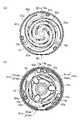
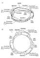
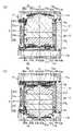
図1は本発明の実施形態に係る振動アクチュエータの分解斜視図、図2は(a)振動アクチュエータの第1カバーケース及び第1弾性部材を省いた状態の上面図及び(b)さらに第1ダンパを省いた状態の上面図、図3は振動アクチュエータの斜視図、図4は振動アクチュエータの断面図、図5は(a)インナーガイドの斜視図、(b)インナーガイドの上面図である。以下、これらの図に基づき振動アクチュエータの構成について説明する。 1 is an exploded perspective view of the vibration actuator according to the embodiment of the present invention, FIG. 2 is (a) a top view of the vibration actuator with the first cover case and the first elastic member omitted, and (b) the first damper. 3 is a perspective view of the vibration actuator, FIG. 4 is a sectional view of the vibration actuator, FIG. 5 is (a) a perspective view of the inner guide, and (b) a top view of the inner guide. The configuration of the vibration actuator will be described below with reference to these drawings.
振動アクチュエータ1は、主に、外殻をなすケース2と、当該ケース2内に設けられた電磁駆動部3と、当該電磁駆動部3により振動可能な可動子4と、当該可動子4の両端をそれぞれ弾性支持する第1支持ユニット5a及び第2支持ユニット5bと、当該第1支持ユニット5a及び第2支持ユニット5bの動きを規制する第1インナーガイド6a及び第2インナーガイド6bと、から構成されている。当該振動アクチュエータ1は、例えば、携帯電話やスマートフォン等の携帯端末、ゲーム機のコントローラ等に搭載される。 The
ケース2は、円筒状のケース本体10の両開口端が第1カバーケース11a及び第2カバーケース11bにより閉じられている。ケース本体10、第1カバーケース11a、及び第2カバーケース11bはそれぞれABS等の樹脂からなる。ケース本体10の外面には、図示しないリード線が接続されるターミナル12が形成されている。 The
電磁駆動部3は、ケース2の内部に配置された円筒状の軟磁性材料でなるヨーク20と、ヨーク20の内面にヨーク20と電気的に絶縁された状態で取り付けられた第1コイル21a及び第2コイル21bと、を有する。 The
第1コイル21a及び第2コイル21bはヨーク20の内面に沿って巻回されている。当該第1コイル21a及び第2コイル21bはそれぞれターミナル12からの通電により磁場を発生可能である。 The
可動子4は、第1コイル21a及び第2コイル21bに包囲され、振動軸Oに沿って振動するよう配置されている。可動子4は、円板状のマグネット30と、マグネット30を挟むように配置された円板状の第1ポールピース31a、第2ポールピース31bと、マグネット30、第1ポールピース31a、第2ポールピース31bを挟むように配置される第1マス(ウエイト、錘)32a、第2マス(ウエイト、錘)32bと、から構成されている。 The
マグネット30は着磁方向が振動軸O方向である。第1ポールピース31a、第2ポールピース31bは、軟磁性材料でなり、マグネット30の磁気吸着力及び接着剤等により、マグネット30に取り付けられている。第1マス32aと第2マス32bは非磁性体からなり、それぞれ接着剤等により、第1ポールピース31a、第2ポールピース31bに取り付けられている。このため、可動子4を構成するマグネット30、第1ポールピース31a、第2ポールピース31b、第1マス32a、第2マス32bは一体化されている。なお、これらのマグネット30、第1ポールピース31a、第2ポールピース31b、第1マス32a、第2マス32bの一体化は、上述した磁気吸着力や接着剤による取り付けに限定されるものではない。ねじ止め等の機械的手段やその他の手段により固定することにより、一体化してもよい。第1マス32a、第2マス32bは、第1ポールピース31a、第2ポールピース31bとの当接面が平坦に形成されているが、この当接面と逆側の面は、振動軸Oを中心軸とし、その中心軸上の先端部33a、33bが最も外方に突出した螺旋形状に形成されている。 The magnetization direction of the
このように構成された可動子4は、振動軸O方向における両端部、即ち第1マス32a及び第2マス32bのそれぞれの先端部33a、33bが第1支持ユニット5a及び第2支持ユニット5bにより支持されている。 The
第1支持ユニット5aは、第1ダンパ40a(第1板バネ)と、当該第1ダンパ40aの一面に設けられた第1弾性部材41aと、から構成されている。 The
図2(a)に示すように、第1ダンパ40aは、孔50a(図4に図示)を有する支持部51aが中央部に形成されている。第1ダンパ40aは孔50aを通して可動子4と連結されている。詳しくは、孔50aに第1マス32aの先端部33aを挿通し、当該先端部33aが押し潰されることでかしめられている。なお、第1ダンパ40aと可動子4との固定手段はかしめに限定されるものではなく、ねじ止めや接着等の他の方法により固定(連結)することもできる。 As shown in FIG. 2(a), the
また第1ダンパ40aは、支持部51aから外周へ渦巻き状に延びる3つの腕部52aを有している。各腕部52aは振動軸Oの回りに120°ピッチで等間隔に形成されている。そして、各腕部52aの外周端はケース本体10の内面に沿った環状の枠部53aに連結されている。当該枠部53aは、振動軸Oの回りに120°ピッチの位置にて、ケース本体10の内面の3か所にて径方向内側に突出しているフランジ部13a(図2(b)に図示)にて連結されている。詳しくは、フランジ部13aから立設したボス部14aを第1ダンパ40aの枠部53aに形成された貫通孔に挿通した状態で、ボス部14aの先端を加熱・加圧し、押し潰すことでかしめている。枠部53aと第1ダンパ40aとの固定手段はかしめに限定されるものではなく、ねじ止めや接着等の他の方法により固定(連結)することもできる。 The
第1ダンパ40aは、金属の一枚ないし複数枚の板バネで構成されており、例えば本実施形態ではステンレス(バネ材)の薄板を加工したものを使用している。第1ダンパ40aの材料は、金属に限らず樹脂や繊維を含む複合素材であってもよい。疲労に強く、可撓性に優れた材料が望ましい。 The
このように構成された第1ダンパ40aは、振動軸O方向及び当該振動軸Oに垂直な径方向を含む交差方向において所定の範囲で弾性変形可能である。なお、この所定の範囲は、振動アクチュエータ1として通常に使用した場合の可動子4の振幅範囲に相当する。従って、当該所定の範囲は、少なくとも第1ダンパ40aがケース2に接触しない範囲であり、第1ダンパ40aの弾性変形の限界を超えない範囲である。 The
第1弾性部材41aは、図3に示すように、第1ダンパ40aの支持部51aから各腕部52aの一定の範囲までの形状に沿った外形の板状をなし、第1ダンパ40aの一面に固定されている。詳しくは、第1弾性部材41aは、第1ダンパ40a上に積層された、接着剤でなる第1接着層と、PE(ポリエチレン)でなるPE層と、接着剤でなる第2接着層と、エラストマ(エラストマとしては、熱可塑性ポリウレタンエラストマー(TPU)があるが限定するものではない)でなるエラストマ層とからなっている。そして、第1弾性部材41aの弾性変形(本実施形態では、PE層のずり変形、エラストマ層の曲げ変形)により、第1ダンパ40aの制振を行う。第1弾性部材41aと第1ダンパ40aとの固定手段は、上記の接着によるものに限定されず、樹脂製の第1弾性部材41aを第1ダンパ40aに熱溶着する等、その他の固定手段を用いてもよい。 As shown in FIG. 3, the first
第2支持ユニット5bも、第1支持ユニット5aと同様の構成をなしており、第2ダンパ40b(第2板バネ)及び第2弾性部材41bを有している。なお、本実施形態において第2ダンパ40bと第1ダンパ40aとが同一形状、同材料からなり、第2弾性部材41bと第1弾性部材41aとが同一形状、同材料である。図4に示すように、第2ダンパ40bの3つの腕部52bは孔50bが形成された支持部51bから環状の枠部53bまで延びている。そして、第2ダンパ40bは、孔50bに第2マス32bの先端部33bが挿入され押し潰してかしめられることで可動子4と連結されている。また、第2ダンパ40bは、環状の枠部53bがケース本体10内面から突出している3つのフランジ部13bと、枠部53bに形成された貫通孔をフランジ部13bのボス部14bが挿通し押し潰されてかしめられることで連結されている。なお、第2ダンパ40bの各腕部52bの渦巻き方向は、第1ダンパ40aの各腕部52aの渦巻き方向と逆をなしている。これにより、振動時に可動子4は第1ダンパ40a及び第2ダンパ40bから各々逆方向のトルクを受けるため、振動軸O方向に変位しても振動軸O回りに回転しない。 The
(第1インナーガイド6a、第2インナーガイド6b)
第1インナーガイド6aは振動アクチュエータ1の振動軸O方向の一側であり、第1支持ユニット5aよりも振動軸O方向の他側(ケース2中央側)に設けられている。第2インナーガイド6bは振動アクチュエータ1の振動軸O方向の他側であり、第2支持ユニット5bよりも振動軸O方向の一側(ケース2中央側)に設けられている。つまり、図4に示すように、第1インナーガイド6a及び第2インナーガイド6bは、ケース2内において第1支持ユニット5a及び第2支持ユニット5bよりも振動軸O方向中央側に設けられている。第1インナーガイド6a及び第2インナーガイド6bは、例えばABS等の樹脂で形成されている。ただし第1インナーガイド6a及び第2インナーガイド6bの材料は樹脂に限定されるものでない。(First
The first
図2(b)及び図5(a)、(b)に示すように、第1インナーガイド6aは、ケース本体10の内面に沿った環状の枠部60aを有しており、その枠部60aの振動軸O回り120°ピッチの3か所に、ケース本体10の径方向内側且つ振動軸O方向他側に向けて螺旋状に傾斜した段差部61aが形成されている。当該段差部61aの螺旋形状は、第1ダンパ40aの各腕部52aの渦巻き形状の外周側(基端側)の部分に沿った形状であり、且つ第1ダンパ40aが所定の範囲で弾性変形している際には各腕部52aに接触することなく、当該第1ダンパ40aの変形が所定の範囲を超えた際には各腕部52aと接触する間隔を有している。 As shown in FIGS. 2(b) and 5(a) and (b), the first
詳しくは、各段差部61aは、ケース本体10の内面と平行な面をなす側壁61awと、当該側壁61awから径方向内側に延びる底部61abと、から構成されている。各底部61abの内縁は上面視においてケース本体10の内面と同軸の内周円(同心円)を形成しており、各側壁61awはケース本体10の内面側から当該内周円に向けた円弧状をなしている。第1ダンパ40aが振動軸Oの交差方向において所定の範囲を超えて変形した場合には側壁61awと接触することで当該交差方向の動きを規制し、第1ダンパ40aが振動軸O方向に所定の範囲を超えて変形した場合には底部61abと接触することで当該振動軸O方向の動きを規制する。 Specifically, each stepped
また、各段差部61aには軽量化のための孔62aが形成されている。さらに、第1インナーガイド6aの枠部60aの外周縁側にはケース本体10の各フランジ部13aの形状に合わせて3か所に当該フランジ部13aの形状に沿った切欠部63aが形成されている。 A
このように構成された第1インナーガイド6aは、枠部60aが形成する内周円内を可動子4が振動軸O方向に進退移動可能である。また、当該枠部60aが形成する内周円の内縁は第1コイル21a及び第2コイル21bよりも径方向内側に突出している。 In the first
第2インナーガイド6bは第1インナーガイド6aと同一形状であり、第2インナーガイド6bについても第1インナーガイド6aと同様の構成をなしている。つまり、図5にてかっこ書きの符号で示すように、第1インナーガイド6aと第2インナーガイド6bの各部は対応している。詳しくは第2インナーガイド6bは環状の枠部60bを有しており、枠部60bに側壁61bwと底部61bbを有する段差部61bが形成されている。また、各段差部61bには孔62bが形成され、枠部60bには切欠部63bが形成されている。 The second
(作動)
以上のように構成された振動アクチュエータ1は、第1コイル21a及び第2コイル21bに通電していない状態では、図4に示すように、第1ダンパ40a及び第2ダンパ40bで支持される可動子4は、第1コイル21a及び第2コイル21bの中央に位置している。(activation)
The
可動子4を振動させる際には、ターミナル12を介して、第1コイル21a及び第2コイル21bに、交互に逆極性の磁界を発生する向きに交流を通電させる。即ち、第1コイル21a及び第2コイル21bの隣り合う部分に同極が発生するようになっている。 When the
例えば図6に示す極性の場合、可動子4には実線矢印Aで示す振動軸O方向の他側(図6における下方)への推力が発生し、第1コイル21a及び第2コイル21bへ流す電流を反転させれば、可動子4には点線矢印Bで示す振動軸O方向の一側(図6における上方)への推力が発生する。 For example, in the case of the polarity shown in FIG. 6, a thrust is generated in the
このように、第1コイル21a及び第2コイル21bに交流を通電させれば、可動子4は第1ダンパ40a及び第2ダンパ40bによる付勢力を両側から受けながら、振動軸Oに沿って振動する。 In this manner, when alternating current is applied to the
ところで、可動子4に発生する推力は、基本的にはフレミングの左手の法則に基づいて与えられる推力に準じられる。本実施形態では、第1コイル21a、第2コイル21bがケース2に固定されているので、マグネット30等が取り付けられた可動子4に第1コイル21a、第2コイル21bに発生する力の反力としての推力が発生する。 By the way, the thrust generated in the
よって、推力に寄与するのは、可動子4のマグネット30の磁束の水平成分(マグネット30の軸方向に直交する成分)である。そして、ヨーク20はマグネット30の磁束の水平成分を増大するものである。 Therefore, it is the horizontal component (the component perpendicular to the axial direction of the magnet 30) of the magnetic flux of the
このように可動子4の通常の振動時は、第1ダンパ40a及び第2ダンパ40bは振動軸O方向及び径方向において所定の範囲で弾性変形し、第1インナーガイド6a及び第2インナーガイド6bに接触することはない。 As described above, during normal vibration of the
一方で、例えば振動アクチュエータ1を搭載した機器が落下した場合等で振動アクチュエータ1に外部から衝撃が加わると、可動子4が過剰な振幅で動き第1ダンパ40a及び第2ダンパ40bが所定の範囲を超えた動きをすることがあるが、第1インナーガイド6a及び第2インナーガイド6bと接触することでこの動きが規制される。 On the other hand, if an external impact is applied to the
具体的には図7(a)に示すように、可動子4が振動軸O方向一側に過剰振幅し、第1ダンパ40a及び第2ダンパ40bが所定の範囲を超える動きをした場合、第2ダンパ40bの腕部53bが、第2インナーガイド6bの段差部61bの底部61bbと接触する。これにより、可動子4がそれ以上振動軸O方向一側に移動することが規制され、可動子4はケース2(第1カバーケース11a)と接触することが防止される。 Specifically, as shown in FIG. 7(a), when the
また、図7(b)に示すように、可動子4が振動軸O方向他側に過剰振幅し、第1ダンパ40a及び第2ダンパ40bが所定の範囲を超える動きをした場合、第1ダンパ40aの腕部52aが、第1インナーガイド6aの段差部61aの底部61abと接触する。これにより、可動子4がそれ以上振動軸O方向他側に移動することが規制され、可動子4はケース2(第2カバーケース11b)と接触することが防止される。 Further, as shown in FIG. 7(b), when the
図示しないが、ケース2に径方向の衝撃が加わった場合は、可動子4も径方向に移動する。このような場合に、可動子4が径方向に移動し、第1ダンパ40a及び第2ダンパ40bが径方向における所定の範囲を超える動きをすると、第1ダンパ40a及び第2ダンパ40bの腕部52a,52bが、第1インナーガイド6a及び第2インナーガイド6bの段差部61a、61bの側壁61aw、61bwと接触する。これにより、可動子4がそれ以上ケース2の径方向に移動することが規制され、可動子4はケース2と接触することが防止される。なお、必ずしも第1ダンパ40a及び第2ダンパ40bの両方が、対応する第1インナーガイド6a及び第2インナーガイド6bと接触する必要はなく、片方が接触しても同様の効果を奏する。 Although not shown, when a radial impact is applied to the
このように本実施形態における振動アクチュエータ1によれば、第1インナーガイド6a及び第2インナーガイド6bが第1ダンパ40a及び第2ダンパ40bの動きを規制することで、可動子4の過剰振幅を抑制することができる。また、第1ダンパ40a及び第2ダンパ40bは板バネで構成されているから、第1インナーガイド6a及び第2インナーガイド6bが第1ダンパ40a及び第2ダンパ40bに接触した際には第1ダンパ40a及び第2ダンパ40bが弾性変形し、衝撃を吸収できる。また、第1インナーガイド6a及び第2インナーガイド6bは第1ダンパ40a及び第2ダンパ40bより振動軸O方向においてケース2の内側に設けられていることから、ケース2の大型化を防ぐことができる。これにより、振動アクチュエータ1の大型化を防ぎつつ、外部からの衝撃が生じた際の可動子4への衝撃を抑制することができる。 As described above, according to the
特に、第1インナーガイド6a及び第2インナーガイド6bは、第1ダンパ40a及び第2ダンパ40bの振動軸O方向における動きを規制することで、可動子4の振動軸O方向の過剰振幅を抑制することができる。 In particular, the first
また、第1インナーガイド6a及び第2インナーガイド6bは、第1ダンパ40a及び第2ダンパ40bのケース2の径方向を含む振動軸Oの交差方向における動きを規制することで、可動子4の径方向の動きを抑制することができる。 In addition, the first
第1インナーガイド6a及び第2インナーガイド6bは、第1ダンパ40a及び第2ダンパ40bの腕部52a,52bの渦巻き形状に対応し振動軸O方向を中心とした螺旋状の段差部61a、61bを有することで、第1ダンパ40a及び第2ダンパ40bの形状に合わせて振動軸O方向及び振動軸Oの交差方向の動きを規制することができる。また、段差部61a,61bは、可動子4の振動時における各腕部52a、52bの形状に沿った底部61ab、61bbを有するので、腕部52a、52bと底部61ab、61bbとを面接触させることができ、衝撃を分散できる。 The first
また、第1インナーガイド6aは振動軸O方向において電磁駆動部3と第1ダンパ(第1板バネ)40aとの間に、第2インナーガイド6bは振動軸O方向において電磁駆動部3と第2ダンパ(第2板バネ)40bとの間に、それぞれ位置していることで、電磁駆動部3と第1ダンパ40a及び第2ダンパ40bとの接触を防止できる。 The first
さらに、第1インナーガイド6a及び第2インナーガイド6bは、枠部60a、60bの内周円の内縁が第1コイル21a及び第2コイル21bよりも径方向内側(可動子4側)に突出していることで、第1コイル21a及び第2コイル21bとの接触をより確実に防止することができる。 Further, in the first
また、可動子4の両端を支持する第1ダンパ40a及び第2ダンパ40bを設け、これに対応する第1インナーガイド6a及び第2インナーガイド6bによって振動軸O方向の一側方向と他側方向の規制をそれぞれ担当することで、インナーガイドの占有スペースを小さくでき、小型化することができる。 Further, a
以上で本発明の実施形態の説明を終えるが、本発明の態様はこの実施形態に限定されるものではない。 Although the description of the embodiment of the present invention is finished above, the aspect of the present invention is not limited to this embodiment.
例えば、上記実施形態では、可動子4を支持する第1支持ユニット5a及び第2支持ユニット5bは、渦巻き状の腕部52a,52bを有する第1ダンパ40a及び第2ダンパ40bを使用しているが、支持ユニットとしてはその他の板バネを用いてもよい。例えば、曲線だけでなく直線を組み合わせた変則的な渦巻き状、十字状や卍状の板バネを用いてもよい。この場合、インナーガイドも板バネの形状に沿った形状とする。 For example, in the above-described embodiment, the
また、上記実施形態では、第1支持ユニット5a及び第2支持ユニット5bは第1弾性部材41a及び第2弾性部材41bを有しているが、必ずしも弾性部材を有していなくてもよい。 In the above embodiment, the
また、上記実施形態のケース2は円筒状をなしており、可動子4は略円柱状をなしているが、ケース及び可動子の形状はこれに限られるものではなく、多角形やその他の形状であってもよい。 Further, although the
1 振動アクチュエータ
2 ケース
3 電磁駆動部
4 可動子
5a 第1支持ユニット
5b 第2支持ユニット
6a 第1インナーガイド
6b 第2インナーガイド
40a 第1ダンパ(板バネ、第1板バネ)
40b 第2ダンパ(板バネ、第2板バネ)
61a、61b 段差部
REFERENCE SIGNS
40b second damper (leaf spring, second leaf spring)
61a, 61b stepped portion
Claims (6)
Translated fromJapanese前記ケースの内部に設けられた電磁駆動部と、
前記電磁駆動部により振動可能な可動子と、
前記ケースの内部に前記可動子を支持する複数の腕部を有する板バネと、
前記ケースの内部で前記可動子の振動軸方向において前記板バネより前記ケース中央側に位置して、前記板バネの動きを規制するインナーガイドと、
を備え、
前記インナーガイドは、内縁が前記電磁駆動部の内面よりも前記可動子側に突出している
ことを特徴とする振動アクチュエータ。a tubular case,
an electromagnetic drive section provided inside the case;
a movable element that can be vibrated by the electromagnetic driving unit;
a leaf spring having a plurality of arms supporting the mover inside the case;
an inner guide located inside the case on the center side of the case relative to the leaf spring in the vibration axis direction of the mover and restricting movement of the leaf spring;
with
The vibrationactuator, wherein the inner guide has an inner edge that protrudes toward the mover from the inner surface of the electromagnetic drive unit .
前記インナーガイドは、前記板バネの渦巻き形状に対応し前記振動軸方向を中心とした螺旋状の段差部を有することを特徴とする請求項1から3のいずれか一項に記載の振動アクチュエータ。the arm of the leaf spring has a spiral shape,
4. The vibration actuator according to any one of claims 1 to 3, wherein the inner guide has a spiral stepped portion centered on the vibration axis direction corresponding to the spiral shape of the leaf spring.
前記インナーガイドは、前記第1板バネの動きを規制する第1インナーガイドと、前記第2板バネの動きを規制する第2インナーガイドと、を有することを特徴とする請求項1から5のいずれか一項に記載の振動アクチュエータ。
The leaf spring has a first leaf spring that supports one side end of the mover and a second leaf spring that supports the other side end of the mover,
6. The method according to any one of claims 1 to5 , wherein the inner guide has a first inner guide that restricts movement of the first leaf spring and a second inner guide that restricts movement of the second leaf spring. Vibration actuator according to any one of the preceding claims.
Priority Applications (5)
| Application Number | Priority Date | Filing Date | Title |
|---|---|---|---|
| JP2018177950AJP7186563B2 (en) | 2018-09-21 | 2018-09-21 | vibration actuator |
| EP19862936.2AEP3855607A4 (en) | 2018-09-21 | 2019-09-17 | VIBRATING ACTUATOR |
| CN201980061873.4ACN112805909B (en) | 2018-09-21 | 2019-09-17 | Vibration actuator |
| PCT/JP2019/036353WO2020059701A1 (en) | 2018-09-21 | 2019-09-17 | Vibrating actuator |
| US17/278,106US12003155B2 (en) | 2018-09-21 | 2019-09-17 | Oscillatory actuator |
Applications Claiming Priority (1)
| Application Number | Priority Date | Filing Date | Title |
|---|---|---|---|
| JP2018177950AJP7186563B2 (en) | 2018-09-21 | 2018-09-21 | vibration actuator |
Publications (2)
| Publication Number | Publication Date |
|---|---|
| JP2020054018A JP2020054018A (en) | 2020-04-02 |
| JP7186563B2true JP7186563B2 (en) | 2022-12-09 |
Family
ID=69887061
Family Applications (1)
| Application Number | Title | Priority Date | Filing Date |
|---|---|---|---|
| JP2018177950AActiveJP7186563B2 (en) | 2018-09-21 | 2018-09-21 | vibration actuator |
Country Status (5)
| Country | Link |
|---|---|
| US (1) | US12003155B2 (en) |
| EP (1) | EP3855607A4 (en) |
| JP (1) | JP7186563B2 (en) |
| CN (1) | CN112805909B (en) |
| WO (1) | WO2020059701A1 (en) |
Families Citing this family (7)
| Publication number | Priority date | Publication date | Assignee | Title |
|---|---|---|---|---|
| JP7063691B2 (en) | 2018-04-06 | 2022-05-09 | フォスター電機株式会社 | Vibration actuator |
| JP7186563B2 (en)* | 2018-09-21 | 2022-12-09 | フォスター電機株式会社 | vibration actuator |
| JP7217810B2 (en)* | 2020-07-02 | 2023-02-03 | フォスター電機株式会社 | vibration actuator |
| JP7543816B2 (en)* | 2020-10-02 | 2024-09-03 | ニデック株式会社 | Vibration motor |
| JP7560326B2 (en)* | 2020-11-10 | 2024-10-02 | フォスター電機株式会社 | Vibration Actuator |
| JP2023006579A (en)* | 2021-06-30 | 2023-01-18 | ミネベアミツミ株式会社 | Vibration actuator and electric apparatus |
| JP7653869B2 (en)* | 2021-08-31 | 2025-03-31 | フォスター電機株式会社 | Actuator |
Citations (2)
| Publication number | Priority date | Publication date | Assignee | Title |
|---|---|---|---|---|
| WO1999039843A1 (en) | 1998-02-06 | 1999-08-12 | Namiki Seimitsu Houseki Kabushiki Kaisha | Electromagnetic actuator and structure for mounting the same |
| JP2016030251A (en) | 2014-07-30 | 2016-03-07 | 日本電産サンキョー株式会社 | Linear actuator |
Family Cites Families (18)
| Publication number | Priority date | Publication date | Assignee | Title |
|---|---|---|---|---|
| CA1264636A (en) | 1984-07-19 | 1990-01-23 | Florence Stoffel | Sterile surgical needle having dark non-reflective surface |
| JPS6145745U (en) | 1984-08-30 | 1986-03-26 | パイオニア株式会社 | Reel motor control circuit |
| US5187612A (en)* | 1990-11-15 | 1993-02-16 | Gap Technologies, Inc. | Gyrating programmable scanner |
| JP3163900B2 (en)* | 1994-05-19 | 2001-05-08 | 日産自動車株式会社 | Anti-vibration support device |
| US6203292B1 (en) | 1997-04-20 | 2001-03-20 | Matsushita Refrigeration Company | Oscillation-type compressor |
| JP3950043B2 (en) | 2002-12-13 | 2007-07-25 | 株式会社シコー技研 | Electromagnetic actuator |
| JP2005152855A (en)* | 2003-11-28 | 2005-06-16 | Teikoku Tsushin Kogyo Co Ltd | Vibration generator |
| JP4941699B2 (en)* | 2005-11-11 | 2012-05-30 | シンフォニアテクノロジー株式会社 | Outer movable linear actuator |
| JP5474799B2 (en)* | 2009-04-08 | 2014-04-16 | 東海ゴム工業株式会社 | Active vibration damper and manufacturing method of active vibration damper |
| KR101092626B1 (en)* | 2010-01-14 | 2011-12-13 | 주식회사 우성지앤티 | Linear vibration motor |
| JP5888867B2 (en)* | 2011-03-31 | 2016-03-22 | 日本電産コパル株式会社 | Vibration actuator |
| JP2015070730A (en) | 2013-09-30 | 2015-04-13 | 日本電産コパル株式会社 | Vibration actuator |
| KR101547572B1 (en) | 2013-11-07 | 2015-08-27 | 자화전자(주) | Linear vibration generating device |
| CN106575913B (en) | 2014-07-30 | 2019-11-05 | 日本电产三协株式会社 | linear actuator |
| JP6748342B2 (en)* | 2015-11-13 | 2020-09-02 | ミツミ電機株式会社 | Vibration actuators, wearable terminals, and incoming call notification function devices |
| US20170216665A1 (en) | 2016-02-02 | 2017-08-03 | Scott Mahr | System for Measuring and Reporting Weight-Training Performance Metrics |
| CN109562412A (en) | 2016-08-09 | 2019-04-02 | 日本电产三协株式会社 | Linear Actuator |
| JP7186563B2 (en)* | 2018-09-21 | 2022-12-09 | フォスター電機株式会社 | vibration actuator |
- 2018
- 2018-09-21JPJP2018177950Apatent/JP7186563B2/enactiveActive
- 2019
- 2019-09-17CNCN201980061873.4Apatent/CN112805909B/enactiveActive
- 2019-09-17EPEP19862936.2Apatent/EP3855607A4/enactivePending
- 2019-09-17USUS17/278,106patent/US12003155B2/enactiveActive
- 2019-09-17WOPCT/JP2019/036353patent/WO2020059701A1/ennot_activeCeased
Patent Citations (2)
| Publication number | Priority date | Publication date | Assignee | Title |
|---|---|---|---|---|
| WO1999039843A1 (en) | 1998-02-06 | 1999-08-12 | Namiki Seimitsu Houseki Kabushiki Kaisha | Electromagnetic actuator and structure for mounting the same |
| JP2016030251A (en) | 2014-07-30 | 2016-03-07 | 日本電産サンキョー株式会社 | Linear actuator |
Also Published As
| Publication number | Publication date |
|---|---|
| EP3855607A1 (en) | 2021-07-28 |
| US12003155B2 (en) | 2024-06-04 |
| US20210351680A1 (en) | 2021-11-11 |
| WO2020059701A1 (en) | 2020-03-26 |
| CN112805909A (en) | 2021-05-14 |
| EP3855607A4 (en) | 2021-11-10 |
| CN112805909B (en) | 2024-09-13 |
| JP2020054018A (en) | 2020-04-02 |
Similar Documents
| Publication | Publication Date | Title |
|---|---|---|
| JP7186563B2 (en) | vibration actuator | |
| JP7313159B2 (en) | vibration actuator | |
| JP7501840B2 (en) | Vibration actuator and electronic device | |
| CN112054645B (en) | Vibration actuators and electronic devices | |
| JP2021107083A (en) | Vibration actuator and electronic equipment | |
| CN106329870A (en) | Linear vibrating motor | |
| JP7275089B2 (en) | vibration actuator | |
| JP7726518B2 (en) | Vibration Actuator | |
| JP7560326B2 (en) | Vibration Actuator | |
| JP7217810B2 (en) | vibration actuator | |
| JP7664696B2 (en) | Vibration Actuator | |
| JP2025003067A (en) | Stimulation device and wearable device | |
| JP2019134509A (en) | Vibration motor | |
| JP2022076635A (en) | Vibration actuator | |
| JP2022072473A (en) | Vibration actuator | |
| JP7250610B2 (en) | Vibration actuators and haptic devices | |
| KR102768936B1 (en) | Linear motor | |
| KR20130139486A (en) | A small and functional vibration device |
Legal Events
| Date | Code | Title | Description |
|---|---|---|---|
| A621 | Written request for application examination | Free format text:JAPANESE INTERMEDIATE CODE: A621 Effective date:20210628 | |
| A131 | Notification of reasons for refusal | Free format text:JAPANESE INTERMEDIATE CODE: A131 Effective date:20220517 | |
| A521 | Request for written amendment filed | Free format text:JAPANESE INTERMEDIATE CODE: A523 Effective date:20220706 | |
| TRDD | Decision of grant or rejection written | ||
| A01 | Written decision to grant a patent or to grant a registration (utility model) | Free format text:JAPANESE INTERMEDIATE CODE: A01 Effective date:20221115 | |
| A61 | First payment of annual fees (during grant procedure) | Free format text:JAPANESE INTERMEDIATE CODE: A61 Effective date:20221129 | |
| R150 | Certificate of patent or registration of utility model | Ref document number:7186563 Country of ref document:JP Free format text:JAPANESE INTERMEDIATE CODE: R150 |