JP7186241B2 - Vehicle driving support method, vehicle driving support device, and automatic driving system - Google Patents
Vehicle driving support method, vehicle driving support device, and automatic driving systemDownload PDFInfo
- Publication number
- JP7186241B2 JP7186241B2JP2020559093AJP2020559093AJP7186241B2JP 7186241 B2JP7186241 B2JP 7186241B2JP 2020559093 AJP2020559093 AJP 2020559093AJP 2020559093 AJP2020559093 AJP 2020559093AJP 7186241 B2JP7186241 B2JP 7186241B2
- Authority
- JP
- Japan
- Prior art keywords
- vehicle
- information
- lane section
- statistical
- travel
- Prior art date
- Legal status (The legal status is an assumption and is not a legal conclusion. Google has not performed a legal analysis and makes no representation as to the accuracy of the status listed.)
- Active
Links
- 238000000034methodMethods0.000titleclaimsdescription13
- 239000000523sampleSubstances0.000claimsdescription51
- 239000000284extractSubstances0.000claimsdescription9
- 238000009825accumulationMethods0.000claimsdescription5
- 230000004927fusionEffects0.000claimsdescription4
- 230000005540biological transmissionEffects0.000claimsdescription3
- 238000010586diagramMethods0.000description8
- 230000001133accelerationEffects0.000description4
- 238000004891communicationMethods0.000description4
- 238000007726management methodMethods0.000description4
- 238000001514detection methodMethods0.000description3
- 230000006870functionEffects0.000description2
- 238000005516engineering processMethods0.000description1
- 230000006698inductionEffects0.000description1
- 230000001960triggered effectEffects0.000description1
Images


Classifications
- B—PERFORMING OPERATIONS; TRANSPORTING
- B60—VEHICLES IN GENERAL
- B60W—CONJOINT CONTROL OF VEHICLE SUB-UNITS OF DIFFERENT TYPE OR DIFFERENT FUNCTION; CONTROL SYSTEMS SPECIALLY ADAPTED FOR HYBRID VEHICLES; ROAD VEHICLE DRIVE CONTROL SYSTEMS FOR PURPOSES NOT RELATED TO THE CONTROL OF A PARTICULAR SUB-UNIT
- B60W30/00—Purposes of road vehicle drive control systems not related to the control of a particular sub-unit, e.g. of systems using conjoint control of vehicle sub-units
- B60W30/18—Propelling the vehicle
- B60W30/18009—Propelling the vehicle related to particular drive situations
- B60W30/18159—Traversing an intersection
- B—PERFORMING OPERATIONS; TRANSPORTING
- B60—VEHICLES IN GENERAL
- B60W—CONJOINT CONTROL OF VEHICLE SUB-UNITS OF DIFFERENT TYPE OR DIFFERENT FUNCTION; CONTROL SYSTEMS SPECIALLY ADAPTED FOR HYBRID VEHICLES; ROAD VEHICLE DRIVE CONTROL SYSTEMS FOR PURPOSES NOT RELATED TO THE CONTROL OF A PARTICULAR SUB-UNIT
- B60W60/00—Drive control systems specially adapted for autonomous road vehicles
- B60W60/001—Planning or execution of driving tasks
- B—PERFORMING OPERATIONS; TRANSPORTING
- B60—VEHICLES IN GENERAL
- B60W—CONJOINT CONTROL OF VEHICLE SUB-UNITS OF DIFFERENT TYPE OR DIFFERENT FUNCTION; CONTROL SYSTEMS SPECIALLY ADAPTED FOR HYBRID VEHICLES; ROAD VEHICLE DRIVE CONTROL SYSTEMS FOR PURPOSES NOT RELATED TO THE CONTROL OF A PARTICULAR SUB-UNIT
- B60W30/00—Purposes of road vehicle drive control systems not related to the control of a particular sub-unit, e.g. of systems using conjoint control of vehicle sub-units
- B60W30/10—Path keeping
- B—PERFORMING OPERATIONS; TRANSPORTING
- B60—VEHICLES IN GENERAL
- B60W—CONJOINT CONTROL OF VEHICLE SUB-UNITS OF DIFFERENT TYPE OR DIFFERENT FUNCTION; CONTROL SYSTEMS SPECIALLY ADAPTED FOR HYBRID VEHICLES; ROAD VEHICLE DRIVE CONTROL SYSTEMS FOR PURPOSES NOT RELATED TO THE CONTROL OF A PARTICULAR SUB-UNIT
- B60W60/00—Drive control systems specially adapted for autonomous road vehicles
- B60W60/001—Planning or execution of driving tasks
- B60W60/0011—Planning or execution of driving tasks involving control alternatives for a single driving scenario, e.g. planning several paths to avoid obstacles
- G—PHYSICS
- G01—MEASURING; TESTING
- G01C—MEASURING DISTANCES, LEVELS OR BEARINGS; SURVEYING; NAVIGATION; GYROSCOPIC INSTRUMENTS; PHOTOGRAMMETRY OR VIDEOGRAMMETRY
- G01C21/00—Navigation; Navigational instruments not provided for in groups G01C1/00 - G01C19/00
- G01C21/38—Electronic maps specially adapted for navigation; Updating thereof
- G01C21/3804—Creation or updating of map data
- G01C21/3807—Creation or updating of map data characterised by the type of data
- G01C21/3815—Road data
- G01C21/3819—Road shape data, e.g. outline of a route
- G—PHYSICS
- G01—MEASURING; TESTING
- G01C—MEASURING DISTANCES, LEVELS OR BEARINGS; SURVEYING; NAVIGATION; GYROSCOPIC INSTRUMENTS; PHOTOGRAMMETRY OR VIDEOGRAMMETRY
- G01C21/00—Navigation; Navigational instruments not provided for in groups G01C1/00 - G01C19/00
- G01C21/38—Electronic maps specially adapted for navigation; Updating thereof
- G01C21/3804—Creation or updating of map data
- G01C21/3833—Creation or updating of map data characterised by the source of data
- G01C21/3841—Data obtained from two or more sources, e.g. probe vehicles
- G—PHYSICS
- G08—SIGNALLING
- G08G—TRAFFIC CONTROL SYSTEMS
- G08G1/00—Traffic control systems for road vehicles
- G08G1/01—Detecting movement of traffic to be counted or controlled
- G08G1/0104—Measuring and analyzing of parameters relative to traffic conditions
- G08G1/0125—Traffic data processing
- G08G1/0129—Traffic data processing for creating historical data or processing based on historical data
- G—PHYSICS
- G08—SIGNALLING
- G08G—TRAFFIC CONTROL SYSTEMS
- G08G1/00—Traffic control systems for road vehicles
- G08G1/01—Detecting movement of traffic to be counted or controlled
- G08G1/0104—Measuring and analyzing of parameters relative to traffic conditions
- G08G1/0125—Traffic data processing
- G08G1/0133—Traffic data processing for classifying traffic situation
- G—PHYSICS
- G08—SIGNALLING
- G08G—TRAFFIC CONTROL SYSTEMS
- G08G1/00—Traffic control systems for road vehicles
- G08G1/01—Detecting movement of traffic to be counted or controlled
- G08G1/0104—Measuring and analyzing of parameters relative to traffic conditions
- G08G1/0137—Measuring and analyzing of parameters relative to traffic conditions for specific applications
- G08G1/0141—Measuring and analyzing of parameters relative to traffic conditions for specific applications for traffic information dissemination
- G—PHYSICS
- G08—SIGNALLING
- G08G—TRAFFIC CONTROL SYSTEMS
- G08G1/00—Traffic control systems for road vehicles
- G08G1/09—Arrangements for giving variable traffic instructions
- G08G1/0962—Arrangements for giving variable traffic instructions having an indicator mounted inside the vehicle, e.g. giving voice messages
- G08G1/0967—Systems involving transmission of highway information, e.g. weather, speed limits
- G08G1/096708—Systems involving transmission of highway information, e.g. weather, speed limits where the received information might be used to generate an automatic action on the vehicle control
- G08G1/096725—Systems involving transmission of highway information, e.g. weather, speed limits where the received information might be used to generate an automatic action on the vehicle control where the received information generates an automatic action on the vehicle control
- G—PHYSICS
- G08—SIGNALLING
- G08G—TRAFFIC CONTROL SYSTEMS
- G08G1/00—Traffic control systems for road vehicles
- G08G1/09—Arrangements for giving variable traffic instructions
- G08G1/0962—Arrangements for giving variable traffic instructions having an indicator mounted inside the vehicle, e.g. giving voice messages
- G08G1/0967—Systems involving transmission of highway information, e.g. weather, speed limits
- G08G1/096733—Systems involving transmission of highway information, e.g. weather, speed limits where a selection of the information might take place
- G08G1/096758—Systems involving transmission of highway information, e.g. weather, speed limits where a selection of the information might take place where no selection takes place on the transmitted or the received information
- G—PHYSICS
- G08—SIGNALLING
- G08G—TRAFFIC CONTROL SYSTEMS
- G08G1/00—Traffic control systems for road vehicles
- G08G1/09—Arrangements for giving variable traffic instructions
- G08G1/0962—Arrangements for giving variable traffic instructions having an indicator mounted inside the vehicle, e.g. giving voice messages
- G08G1/0967—Systems involving transmission of highway information, e.g. weather, speed limits
- G08G1/096766—Systems involving transmission of highway information, e.g. weather, speed limits where the system is characterised by the origin of the information transmission
- G08G1/096775—Systems involving transmission of highway information, e.g. weather, speed limits where the system is characterised by the origin of the information transmission where the origin of the information is a central station
- G—PHYSICS
- G08—SIGNALLING
- G08G—TRAFFIC CONTROL SYSTEMS
- G08G1/00—Traffic control systems for road vehicles
- G08G1/09—Arrangements for giving variable traffic instructions
- G08G1/0962—Arrangements for giving variable traffic instructions having an indicator mounted inside the vehicle, e.g. giving voice messages
- G08G1/0968—Systems involving transmission of navigation instructions to the vehicle
- G08G1/096805—Systems involving transmission of navigation instructions to the vehicle where the transmitted instructions are used to compute a route
- G08G1/096827—Systems involving transmission of navigation instructions to the vehicle where the transmitted instructions are used to compute a route where the route is computed onboard
- B—PERFORMING OPERATIONS; TRANSPORTING
- B60—VEHICLES IN GENERAL
- B60W—CONJOINT CONTROL OF VEHICLE SUB-UNITS OF DIFFERENT TYPE OR DIFFERENT FUNCTION; CONTROL SYSTEMS SPECIALLY ADAPTED FOR HYBRID VEHICLES; ROAD VEHICLE DRIVE CONTROL SYSTEMS FOR PURPOSES NOT RELATED TO THE CONTROL OF A PARTICULAR SUB-UNIT
- B60W2530/00—Input parameters relating to vehicle conditions or values, not covered by groups B60W2510/00 or B60W2520/00
- B60W2530/201—Dimensions of vehicle
- B—PERFORMING OPERATIONS; TRANSPORTING
- B60—VEHICLES IN GENERAL
- B60W—CONJOINT CONTROL OF VEHICLE SUB-UNITS OF DIFFERENT TYPE OR DIFFERENT FUNCTION; CONTROL SYSTEMS SPECIALLY ADAPTED FOR HYBRID VEHICLES; ROAD VEHICLE DRIVE CONTROL SYSTEMS FOR PURPOSES NOT RELATED TO THE CONTROL OF A PARTICULAR SUB-UNIT
- B60W2556/00—Input parameters relating to data
- B60W2556/45—External transmission of data to or from the vehicle
Landscapes
- Engineering & Computer Science (AREA)
- Physics & Mathematics (AREA)
- General Physics & Mathematics (AREA)
- Radar, Positioning & Navigation (AREA)
- Remote Sensing (AREA)
- Automation & Control Theory (AREA)
- Transportation (AREA)
- Mechanical Engineering (AREA)
- Chemical & Material Sciences (AREA)
- Atmospheric Sciences (AREA)
- Life Sciences & Earth Sciences (AREA)
- Analytical Chemistry (AREA)
- Human Computer Interaction (AREA)
- Traffic Control Systems (AREA)
- Control Of Driving Devices And Active Controlling Of Vehicle (AREA)
Description
Translated fromJapanese本発明は、無車線区間の経路情報を生成して、車両が自動運転により無車線区間を走行するのを支援する走行支援方法、走行支援装置及び、無車線区間を自動運転による走行可能とする自動運転システムに関する。 The present invention provides a driving support method, a driving support device, and a driving support device for generating route information for a no-lane section and supporting a vehicle traveling in the no-lane section by automatic driving, and enabling the vehicle to travel in the no-lane section by automatic driving. Regarding automated driving systems.
自動運転(例えば、SAE(Society of Automotive Engineers)定義によるレベル3以上)では、高度なセンシング技術を利用して車両の走行制御が行われている。一例を示せば、自動運転車両が走行レーンに沿って車線を維持するため、車両は道路に引かれた白線を検出し、道路の横方向の偏差を制御する。特許文献1には、自動運転支援のため道路形状の詳細な情報を得るため、車両の走行情報に基づいて道路形状を特定する道路形状検出システムが開示されている。 In automatic driving (for example, level 3 or higher defined by SAE (Society of Automotive Engineers)), advanced sensing technology is used to control vehicle travel. In one example, as an autonomous vehicle stays in its lane, it detects white lines on the road and controls the lateral deviation of the road.
特許文献1によれば、区画線(白線)が薄くなる等の要因で区画線が認識できない区間においても、自動運転支援を継続して実施することが可能になると記述されている。 According to
しかしながら、車両が走行する道路においては、区画線(白線)のような走行計画を立案するために有用な地物が元々存在しない領域が存在する。例えば、一般道における交差点や、有料道路の料金所付近では、ガイドとなる区画線が存在していない(このような領域を「無車線区間」と呼ぶ)。このような無車線区間において安定した自動運転を実現することができれば、運転者の負担を大幅に軽減することができる。 However, on roads on which vehicles travel, there are areas where features such as lane markings (white lines) that are useful for planning a travel plan originally do not exist. For example, at intersections on general roads and near toll gates on toll roads, there are no lane markings to serve as guides (such areas are called "no-lane sections"). If stable automatic driving can be achieved in such a laneless section, the burden on the driver can be greatly reduced.
なお、特許文献1の道路形状検出システムにおいては、正確な道路形状を特定するため、車線維持走行に係る自動運転支援が実施された状態で走行する車両の走行情報と、車線維持走行に係る自動運転支援が実施されていない状態で走行する車両の走行情報との双方を用いる。このため、特許文献1開示の技術は、そもそも自動運転支援が実施できない区画線のない無車線区間においては適用することができない。 In addition, in the road shape detection system of
本発明の一実施の態様である、無車線区間における車両の走行支援方法は、複数の車両から送信されるプローブ情報を蓄積するプローブ情報蓄積ステップと、プローブ情報蓄積ステップにおいて蓄積されたプローブ情報から無車線区間における車両の走行軌跡情報を抽出し、無車線区間への進入ポイント及び退出ポイントの組み合わせごとに車両の走行軌跡情報を抽出するマッチング処理ステップと、マッチング処理ステップにおいて抽出された無車線区間への進入ポイント及び退出ポイントの組み合わせごとの車両の走行軌跡情報を、複数の基準により複数の区分に仕分けし、複数の区分ごとの走行軌跡情報の統計的処理により統計的軌跡情報を算出する統計処理ステップと、統計処理ステップにおいて算出された統計的軌跡情報を無車線区間における車両の経路情報として複数の車両に送信する経路情報送信ステップとを有し、複数の基準として、車両のホイールベースあるいは車長、及び車両が無車線区間を通過するのに要した通過時間を含む。A vehicle driving support method in a no-lane section, which is one embodiment of the present invention, includes a probe information accumulation step of accumulating probe information transmitted from a plurality of vehicles, and from the probe information accumulated in the probe information accumulation step A matching processing step of extracting vehicle travel trajectory information in a non-lane section and extracting vehicle travel trajectory information for each combination of entry points and exit points into the non-lane section, and a non-lane section extracted in the matching processing step. Statistics for calculating statistical trajectory information by sorting the vehicle trajectory information for each combination of entry points and exit points into multiple categories based onmultiple criteria and statistically processing the trajectory information for each of the multiple categories a processing step; and a route information transmission step of transmitting the statistical trajectory information calculated in the statistical processing step toa plurality of vehicles as vehicle route information in a non-lane section.This includes the length of the vehicle and the transit time required for the vehicle to pass through the no-lane section .
また、本発明の他の一実施の態様である自動運転システムは、自動運転用地図を管理し、自車の位置を推定するマップポジションユニットと、マップポジションユニットからの地図情報に基づき走行計画を立案する走行制御ユニットとを有し、自動運転用地図は、無車線区間について、無車線区間への進入ポイント及び退出ポイントの組み合わせごとに、仕分けされた複数の区分ごとに求められた経路情報を有しており、マップポジションユニットは、自車の走行状態に基づき、無車線区間について複数の区分ごとの経路情報の1または複数を選択し、走行制御ユニットは、マップポジションユニットによって選択された1または複数の経路情報に基づき、無車線区間を含む経路の走行計画を立案し、自動運転用地図における無車線区間についての経路情報は、車両走行支援装置が、複数の車両から送信され、蓄積したプローブ情報から、無車線区間における車両の走行軌跡情報を抽出し、無車線区間への進入ポイント及び退出ポイントの組み合わせごとに車両の走行軌跡情報を抽出し、無車線区間への進入ポイント及び退出ポイントの組み合わせごとの車両の走行軌跡情報を、複数の基準により複数の区分に仕分けし、複数の区分ごとの走行軌跡情報の統計的処理により算出した統計的軌跡情報であり、複数の基準として、車両のホイールベースあるいは車長、及び車両が無車線区間を通過するのに要した通過時間を含む。Further, an automatic driving system, which is another embodiment of the present invention, includes a map position unit that manages a map for automatic driving and estimates the position of the own vehicle, and a driving plan based on the map information from the map position unit. The map for automatic driving has a driving control unit that plans, and the map for automatic driving includes route information obtained for each of a plurality of sorted sectionsfor each combination of entry points and exit points to the no-lane section. The map position unit selects one or more pieces of route information for each of the plurality of sections for the no-lane section based on the running state of the own vehicle, and the cruise control unit selects the one selected by the map position unit.Alternatively, based on multiple pieces of route information, a travel plan for a route including no lane sections is formulated, and the route information for the no lane section on the map for automatic driving is transmitted from multiple vehicles and accumulated by the vehicle driving support device. From the probe information, extract the travel trajectory information of the vehicle in the non-lane section, extract the travel trajectory information of the vehicle for each combination of entry points and exit points to the non-lane section, and extract the entry point and exit point to the non-lane section. Statistical trajectory information calculated by sorting the vehicle trajectory information for each combination into multiple categories based on multiple criteria and statistically processing the trajectory information for each of the multiple categories. wheelbase or length of the vehicle, and transit time required for the vehicle to pass through the no-lane section .
無車線区間においても自動運転を可能とする。 Autonomous driving is possible even in no-lane sections.
その他の課題と新規な特徴は、本明細書の記述および添付図面から明らかになるであろう。 Other problems and novel features will become apparent from the description of the specification and the accompanying drawings.
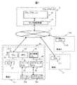
図1に本実施例の車両走行支援システムのブロック図を示す。車両走行支援システムは、ネットワーク3を介して、複数の車両2-1~Nと通信可能に接続されるプローブセンタ1を有している。 FIG. 1 shows a block diagram of the vehicle driving support system of this embodiment. The vehicle driving support system has a
プローブセンタ1は、車両2からのプローブ情報を収集し、無車線区間における車両の走行軌跡を分析するプローブサーバ(車両走行支援装置)11と、プローブサーバ11をネットワーク3に通信可能に接続するセンタ通信装置12とを含む。プローブサーバ11は一般的な計算機システムとして実現できる。クラウド上に実現されてもよい。 The
車両2は、道路を走行する車両であり、ネットワーク3を介して自車の走行軌跡を含むプローブ情報をプローブサーバ11に送信する。車両2には自動運転システム20が搭載されている。自動運転システム20は、例えば、テレマティクス制御ユニット(TCU:Telematics Control Unit)21、マップポジションユニット(MPU:Map Position Unit)23、走行制御ECU(Electronic Control Unit)24、ブレーキECU25、ステアリングECU26、センサ27を含み、これらはCAN(Controller Area Network)のような車載ネットワーク28により通信可能に接続されている。なお、自動運転とは、例えば、SAE(Society of Automotive Engineers)定義によるレベル3以上を想定している。 The
TCU21は、自動運転システム20がネットワーク3等の外部機器と通信を行うための機能ユニットである。各種の無線通信規格に対応するモデムを有し、交通インフラストラクチャー、クラウド、他の自動車等との通信をサポートする。また、この例では、GNSS(全地球航法衛星システム:Global Navigation Satellite System)用アンテナ22が接続され、衛星からの信号も受信可能とされている。 The TCU 21 is a functional unit for the automatic driving system 20 to communicate with external devices such as the network 3 . It has modems that support various wireless communication standards and supports communication with transportation infrastructure, clouds, other vehicles, etc. Also, in this example, an
MPU23は、詳細は後述するが、GNSSによる位置情報や自車のセンサで検知した走行情報等を利用して自車の位置情報をリアルタイムに把握して、プローブ情報としてプローブセンタ1に送信する。また、プローブセンタ1にて自動運転用地図が更新された場合には、更新に係る地図情報を受信して、MPU23が保持する地図情報を更新する。 Although the details will be described later, the MPU 23 grasps the position information of the own vehicle in real time using the position information by GNSS and the traveling information detected by the sensor of the own vehicle, and transmits it to the
走行制御ECU24は、MPU23が保持する地図情報を利用して、走行計画を立案し、立案した走行計画にしたがって自車を制御する。このため、自車の周辺状況や自車の走行状態を把握するため、車両には各種センサ27が設けられており、走行制御ECU24は車載ネットワーク28を介して各種センサ27からの出力を収集している。自動運転システム20が有するセンサ27は特に限定されないが、道路に表示される白線あるいは障害物を認識するためのカメラ、レーザレーダ(LiDAR:Light Detection and Ranging)、ミリ波センサ等、あるいは車両の走行状態を把握するための車速センサ、加速度センサ、角速度センサなどが挙げられる。また、走行計画にしたがって自車を制御するため、ブレーキ25aやステアリング26aなどを制御するアクチュエータコントローラ(ここでは、例としてブレーキECU25、ステアリングECU26を示している)に対して車載ネットワーク28を介して制御信号を出力する。 The travel control ECU 24 utilizes the map information held by the MPU 23 to formulate a travel plan, and controls the own vehicle according to the planned travel plan. Therefore, the vehicle is equipped with
図2に自動運転システム20を構成するECUなどの機能ユニットのハードウェア構成例を図2に示す。機能ユニット200は、プロセッサ201、主記憶202、補助記憶203、ネットワークインタフェース204を含み、これらはバス205により通信可能に結合されている。ネットワークインタフェース204は車載ネットワーク28と接続するためのインタフェースである。補助記憶203は通常、ROM(Read Only Memory)やフラッシュメモリなどの不揮発性メモリで構成され、機能ユニット200が実行するプログラムやプログラムが処理対象とするデータ等を記憶する。主記憶202はRAM(Random Access Memory)で構成され、プロセッサ201の命令により、プログラムやプログラムの実行に必要なデータ等を一時的に記憶する。プロセッサ201は、補助記憶203から主記憶202にロードしたプログラムを実行する。なお、図2は、機能ユニット200の演算機能に関するハードウェア基本構成を示すものであり、機能ユニット200の処理機能に応じて他のハードウェアが搭載されうる。例えば、所定の演算を専門的に実行するDSP(Digital Signal Processor)やPLD(Programmable Logic Device)が搭載されてもよい。また、TCU21には高周波信号を処理するRFモジュールなども搭載される。 FIG. 2 shows a hardware configuration example of functional units such as an ECU that constitute the automatic driving system 20. As shown in FIG.
図3に、車両走行支援システムにおいて、無車線区間における自動運転を実現するフローチャートを示す。まず、車両2-1~NのMPU23は、プローブサーバ11に自車のプローブ情報を送信する(S301)。プローブサーバ11では、車両2-1~Nからのプローブ情報をストレージに蓄積する(S311)。プローブサーバ11は、蓄積されたプローブ情報をもとに、無車線区間における車両の統計的軌跡情報を作成し(S312)、統計的軌跡情報を無車線区間の経路情報として車両2-1~Nに送信する。ステップS312,S313を実行するタイミングは特に限定されないが、定期的に実行する、あるいは新規のプローブ情報が一定以上蓄積されたことをトリガにして実行するようにすればよい。 FIG. 3 shows a flowchart for realizing automatic driving in a no-lane section in the vehicle driving support system. First, the
統計的軌跡情報は、車両2-1~NのMPU23の保有する自動運転用地図の一部を成しており、MPU23はプローブサーバ11からの統計的軌跡情報を受信し、受信した統計的軌跡情報により地図情報を更新する(S302)。車両2の走行制御ECU24は、MPU23が選択した地図情報を用いて走行計画を立案する。このとき、車両2が無車線区間を走行しようとする場合には、無車線区間の経路情報としてプローブサーバ11から送信された統計的軌跡情報を用いて、無車線区間の走行計画を立案する(S303)。 The statistical trajectory information constitutes a part of the map for automatic driving held by the
なお、図1に示した車両走行支援システムにおいて車両2の全てが自動運転システム20を有している必要はない。図3に示したように、本システムでのプロセスは、大きく、車両2のプローブ情報を収集、分析するプロセスと、その結果(統計的軌跡情報)を用いて車両2において走行計画を立案するプロセスとを有している。統計的軌跡情報は、数多くのプローブ情報に基づいて作成されることで信頼性を増す。本実施例では、自動運転システムを搭載している車両を例に説明するが、自動運転システムを搭載していなくても、自車の軌跡情報を必要な精度で収集、送信できる車両からのプローブ情報を統計的軌跡情報の生成に用いることは差し支えない。 Note that not all
図4に、車両走行支援システムが対象とする無車線区間の例を示す。無車線区間400は、進行方向y1の2レーンの道路401、進行方向y1の2レーンの道路402、進行方向y2の2レーンの道路403、進行方向y2の2レーンの道路404、進行方向x1の1レーンの道路405、進行方向x2の1レーンの道路406が交差する領域である。図4に示す無車線区間400において自動運転のための車両走行支援につき、図3のフローチャートにしたがって、以下説明する。 FIG. 4 shows an example of a no-lane section targeted by the vehicle driving support system. The no-
(ステップS301)
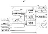
図5にMPU23のブロック図を示す。MPU23のハードウェア基本構成も図2に示したものであり、自動運転用地図500は補助記憶203に蓄積され、後述するMPU23の処理を実行するブロックは、プロセッサ201上で実行されるソフトウェアあるいは専用ハードウェアとして実装される。(Step S301)
FIG. 5 shows a block diagram of the
自動運転用地図500は、走行制御ECU24が走行計画の立案に用いる地図であり、道路はその構造の変化を区切りとして区画されている。図4に示される道路の場合、その構造に応じて、無車線区間400、各道路401~406に区画され、道路のそれぞれにつき、始点位置、終点位置等を含む地図情報として格納されている。自動運転用地図500は、随時最新のものに更新される。このため、地図情報管理部502は、プローブサーバ11からTCU21経由で地図情報の更新情報を受信すると、受信した更新情報にしたがって自動運転用地図500を更新する。 The
MPU23の自車位置推定部503では自車のプローブ情報を作成し、TCU21経由でプローブサーバ11に送信する。ここで、プローブ情報には、少なくとも時刻、当該時刻における自車の位置情報、自車の車両属性と、を含む。ここで、自車の位置を、車両の後輪車軸中心の位置として特定することが望ましい。車両の後輪車軸中心位置は、車両のステアリングによるばらつきの影響を受けにくいためである。自車の位置を推定するため、GNSSからの信号をGNSSチューナ501で復調して得られる位置や方位情報と、車両2に設けられたセンサ情報とを併用する。例えば、車輪の回転速度から車速情報を求める車速センサ27a、加速度センサ27bからの加速度情報、角速度センサ27cからの角速度情報を用いて自車位置を推定する(慣性航法)ことができる。また、車両属性としてはホイールベース、あるいは車長を含むものとする。車長の長いバスやトラックの場合、左折または右折する場合に車長の短い自家用車よりも大回りしなければならず、車両の走行軌跡に影響を及ぼすためである。車両2-1~NのMPU23はプローブ情報を所定の周期(例えば、500msに1回)でプローブサーバ11に送信する。 The own vehicle position estimating unit 503 of the
(ステップS311)
図6にプローブサーバ(車両走行支援装置)11のブロック図を示す。車両位置情報600はサーバのストレージに蓄積され、後述するプローブサーバ11の処理を実行するブロックは、サーバで実行されるソフトウェアあるいは専用ハードウェアとして実装される。(Step S311)
FIG. 6 shows a block diagram of the probe server (vehicle driving support device) 11. As shown in FIG. The
プローブ情報蓄積部601は、車両から送付されたプローブ情報を車両位置情報600に蓄積する。 The probe
(ステップS312)
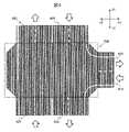
プローブサーバ11のマッチング処理部602(図6参照)ではまず、無車線区間におけるプローブ情報を抽出し、無車線区間に対する進入ポイント及び退出ポイントが同じ車両の走行軌跡情報を抽出する(マッチング処理)。図4に示す無車線区間400の場合、進入ポイントは道路401(2レーン)の終点位置、道路403(2レーン)の終点位置、道路406(1レーン)の終点位置の計5ポイントあり、退出ポイントは道路402(2レーン)の始点位置、道路404(2レーン)の始点位置、道路405(1レーン)の始点位置の計5ポイントある。したがって、無車線区間400の場合の場合、5つの進入ポイントと5つの退出ポイントとの起こりうる組み合わせに対する車両の走行軌跡情報を抽出する。例えば、図7は、道路401の内側レーンの終点位置を進入ポイント701、道路405の始点位置を退出ポイント702としてマッチング処理を行った例であり、点線、破線、一点鎖線、二点鎖線で示されるような走行軌跡情報703が抽出される。(Step S312)
The matching processing unit 602 (see FIG. 6) of the
続いて、統計処理部603は、所定の進入ポイントと退出ポイントの組み合わせについて抽出された走行軌跡情報から、統計的軌跡情報を算出する。これにあたり、走行軌跡情報の仕分けを行う。図8に仕分けの例を示す。図8の例では、仕分けの1つの軸をホイールベース(車長)、もう1つの軸を無車線区間の通過時間とする。仕分けの軸(基準)には、無車線区間における車両の走行軌跡に対して影響を及ぼす要因を選択する。無車線区間の通過時間を基準の一つとしたのは、無車線区間においてカーブを曲がる速度に応じて走行軌跡も変わり、このため、無車線区間の通過時間の近い走行軌跡は近似した軌跡を描いていると考えられるためである。このように、走行軌跡情報を図8の例ではA1~C3の9つの区分に分け、それぞれの区分に属する走行軌跡情報から統計的軌跡情報を算出する。例えば、図7に示される走行軌跡情報703が図8の区分A2に属する走行軌跡情報であったとすれば、図7に実線で示される統計的軌跡情報704を算出する。すなわち、図7に示す進入ポイント701、退出ポイント702の組み合わせに対して、区分の数(この例では9つ)だけの統計的軌跡情報が得られることになる。 Subsequently, the
なお、仕分けの軸の数、仕分けの軸の内容、各軸を区分する数等については任意であり、対象とする無車線区間に応じて設定することができる。 Note that the number of axes for sorting, the contents of the axes for sorting, the number of sections for each axis, and the like are arbitrary, and can be set according to the non-lane section of interest.
図9を用いて、統計的軌跡情報704の算出方法の一例を説明する。進入ポイント701から退出ポイント702までの通過時間を等間隔に4等分して5つの時点(T0~T4)を設定する。各時点での走行軌跡情報における位置情報の分布(統計的位置情報)を求める。図9では、緯度方向の分布を901、経度方向の分布を902として表している。各時点における統計的位置情報からスプライン曲線を生成し、統計的軌跡情報704とする。An example of a method of calculating the
このとき、統計処理部603は信頼度情報も算出することが望ましい。信頼度情報は、例えば、統計的軌跡情報がいくつの走行軌跡から生成されたかに基づいて決定される。元になった走行軌跡が多い程、統計的軌跡情報の信頼性は増すためである。 At this time, it is desirable that the
(ステップS313)
プローブサーバ11の経路情報送信部604(図6参照)は算出した統計的軌跡情報を無車線区間の経路情報として、車両2に送信する。このとき、統計的軌跡情報の信頼度情報もあわせて送信することが望ましい。(Step S313)
The route information transmitting unit 604 (see FIG. 6) of the
(ステップS302)
MPU23の地図情報管理部502(図5参照)は、プローブサーバ11から統計的軌跡情報を受信すると、受信した統計的軌跡情報により自動運転用地図500を更新する。(Step S302)
When the map information management unit 502 (see FIG. 5) of the
(ステップS303)
MPU23の地図情報出力部504(図5参照)は、走行制御ECU24が走行計画の立案に使用する地図情報を自動運転用地図500から抽出して、走行制御ECU24に伝達する。走行経路に無車線区間を含む場合、自車の走行状態に基づき1または複数の統計的軌跡情報を、信頼度情報が存在する場合には信頼度情報とともに伝達する。例えば、自車(ホイールベースは中であるとする)が無車線区間400に進入しようとするとき、その進入速度に応じて、図8に示した区分B1~B3のうち、1または複数を選択して、走行制御ECUに伝達する。(Step S303)
A map information output unit 504 (see FIG. 5) of the
図10に走行制御ECU24のブロック図を示す。走行制御ECU24のハードウェア基本構成も図2に示したものであり、後述する走行制御ECU24の処理を実行するブロックは、プロセッサ201上で実行されるソフトウェアあるいは専用ハードウェアとして実装される。 FIG. 10 shows a block diagram of the running
地図情報受信部1001は、MPU23が抽出した地図情報を受信する。上述のように、無車線区間については、自車の走行状態に基づきMPU23が選択した、1または複数の統計的軌跡情報が含まれている。 A map
センサフュージョン1002では、地図情報に対して、例えば、カメラ27d、ミリ波センサ27e、レーザレーダ27fが把握した周辺情報についてのセンサデータを重ね合わせることにより、自車の周辺状況をより正確に把握する。 In the
走行計画立案部1003では、センサフュージョン1002により把握された自車の周辺状況に基づき走行計画を立案する。無車線区間においてMPU23より複数の候補が伝達されている場合には、把握された自車の周辺状況、複数の候補それぞれの信頼度情報に基づき、1つの統計的軌跡情報が選択される。 A travel
制御信号出力部1004では立案された走行計画に基づき自車を制御するため、アクチュエータコントローラ(ブレーキECU25、ステアリングECU26等)に対する制御信号を生成し、出力する。 A control
このように本実施例では、車両の走行情報に基づき、無車線区間の経路情報を生成することができる。これにより、自動運転システムが適用できる範囲を交通インフラストラクチャーあるいは車両に装備するセンサを高度化あるいはコストアップすることなく実現することができる。例えば、代替案として無車線区間に車両を誘導するための磁気マーカや磁界誘導ケーブルを敷設したり、無車線区間に存在する地物との距離を高精度に認識可能なセンサを車両に搭載したりすることにより、自動運転支援(車両走行支援)を行うことが考えられるが、これらの代替案に比して低コストに自動運転システムが適用できる範囲を拡大することが可能になる。 Thus, in this embodiment, it is possible to generate route information for a no-lane section based on vehicle travel information. As a result, the range to which the automated driving system can be applied can be realized without increasing the sophistication or cost of the sensors installed in the traffic infrastructure or vehicles. For example, as an alternative, we installed magnetic markers and magnetic induction cables to guide the vehicle in the no-lane section, or installed a sensor on the vehicle that can accurately recognize the distance to the features that exist in the no-lane section. It is conceivable to provide automatic driving assistance (vehicle driving assistance) by doing so, but it is possible to expand the range where the automatic driving system can be applied at a lower cost than these alternatives.
以上、本発明者によってなされた発明を実施の形態に基づき具体的に説明したが、本発明は実施の形態に限定されるものではなく、その要旨を逸脱しない範囲で種々変更可能である。例えば、対象とする無車線区間は図4に示したものに限られず、図11に示すような有料道路の料金所が設けられた区間についても適用できる。図11の例では、ゲート1100が設けられた領域と進行方向a1の1レーンの道路1104、進行方向b2の2レーンの道路1105とに挟まれた無車線区間1101、及びゲート1100が設けられた領域と進行方向b1の1レーンの道路1103、進行方向a2の2レーンの道路1106とに挟まれた無車線区間1102の2つの無車線区間を有している。上述のように、自動運転用地図では、道路はその構造の変化を区切りとして区画されているため、ゲート1100が設けられた領域を境として2つの無車線区間が存在している。しかしながら、車両の運転手は最短で料金所を抜けられるよう、ゲート1100のいずれかを選択するに過ぎないため、ゲート1100が設けられた領域と無車線区間1101,1102とを含む領域を仮想的無車線区間1110として扱って、統計的軌跡情報を算出すればよい。 Although the invention made by the inventor has been specifically described above based on the embodiment, the invention is not limited to the embodiment, and can be variously modified without departing from the scope of the invention. For example, the non-lane sections to be targeted are not limited to those shown in FIG. 4, but can also be applied to sections of toll roads provided with toll gates as shown in FIG. In the example of FIG. 11, a no-
1:プローブセンタ、2:車両、3:ネットワーク:11:プローブサーバ(車両走行支援装置)、12:センタ通信装置、20:自動運転システム、21:テレマティクス制御ユニット、22:GNSS用アンテナ、23:マップポジションユニット、24:走行制御ECU、25:ブレーキECU、25a:ブレーキ、26:ステアリングECU、26a:ステアリング、27:センサ、27a:車速センサ、27b:加速度センサ、27c:角速度センサ、28:車載ネットワーク、200:機能ユニット、201:プロセッサ、202:主記憶、203:補助記憶、204:ネットワークインタフェース、205:バス、400,1101,1102:無車線区間、401,402,403,404,405,406,1103,1104,1105,1106:道路、500:自動運転用地図、501:GNSSチューナ、502:地図情報管理部、503:自車位置推定部、504:地図情報出力部、600:車両位置情報、601:プローブ情報蓄積部、602:マッチング処理部、603:統計処理部、604:経路情報送信部、701:進入ポイント、702:退出ポイント、703:走行軌跡情報、704:統計的軌跡情報、901:緯度方向の統計的位置情報、902:経度方向の統計的位置情報、1001:地図情報受信部、1002:センサフュージョン、1003:走行計画立案部、1004:制御信号出力部、1100:ゲート、1110:仮想的無車線区間。1: probe center, 2: vehicle, 3: network: 11: probe server (vehicle driving support device), 12: center communication device, 20: automatic driving system, 21: telematics control unit, 22: GNSS antenna, 23: Map position unit 24: Driving control ECU 25: Brake ECU 25a: Brake 26: Steering ECU 26a: Steering 27: Sensor 27a: Vehicle speed sensor 27b: Acceleration sensor 27c: Angular velocity sensor 28: On-vehicle network, 200: functional unit, 201: processor, 202: main memory, 203: auxiliary memory, 204: network interface, 205: bus, 400, 1101, 1102: laneless section, 401, 402, 403, 404, 405, 406, 1103, 1104, 1105, 1106: road, 500: automatic driving map, 501: GNSS tuner, 502: map information management unit, 503: own vehicle position estimation unit, 504: map information output unit, 600: vehicle position Information 601: Probe information storage unit 602: Matching processing unit 603: Statistical processing unit 604: Route information transmission unit 701: Entry point 702: Exit point 703: Running track information 704: Statistical track information 901: Statistical position information in the latitudinal direction 902: Statistical positional information in the longitude direction 1001: Map information receiving unit 1002: Sensor fusion 1003: Travel planning unit 1004: Control signal output unit 1100: Gate , 1110: Virtual no-lane section.
Claims (12)
Translated fromJapanese複数の車両から送信されるプローブ情報を蓄積するプローブ情報蓄積ステップと、
前記プローブ情報蓄積ステップにおいて蓄積されたプローブ情報から前記無車線区間における車両の走行軌跡情報を抽出し、前記無車線区間への進入ポイント及び退出ポイントの組み合わせごとに車両の走行軌跡情報を抽出するマッチング処理ステップと、
前記マッチング処理ステップにおいて抽出された前記無車線区間への進入ポイント及び退出ポイントの組み合わせごとの車両の走行軌跡情報を、複数の基準により複数の区分に仕分けし、前記複数の区分ごとの前記走行軌跡情報の統計的処理により統計的軌跡情報を算出する統計処理ステップと、
前記統計処理ステップにおいて算出された前記統計的軌跡情報を前記無車線区間における車両の経路情報として複数の車両に送信する経路情報送信ステップとを有し、
前記複数の基準として、車両のホイールベースあるいは車長、及び車両が前記無車線区間を通過するのに要した通過時間を含む車両の走行支援方法。A driving support method for a vehicle in a no-lane section,
A probe information accumulation step of accumulating probe information transmitted from a plurality of vehicles;
Matching for extracting vehicle trajectory information in the non-lane section from the probe information accumulated in the probe information accumulating step, and extracting vehicle trajectory information for each combination of entry points and exit points into the non-lane section. a processing step;
The vehicle travel trajectory information for each combination of entry points and exit points into the non-lane section extracted in the matching processing step is sorted into a plurality of categories based ona plurality of criteria, and the travel trajectory for each of the plurality of categories. a statistical processing step of calculating statistical trajectory information by statistical processing of information;
a route information transmission step of transmitting the statistical trajectory information calculated in the statistical processing step to a plurality of vehicles as vehicle route information in the no-lane section;
A vehicle driving support methodincluding, as the plurality of criteria, a wheel base or vehicle length of the vehicle and a passage time required for the vehicle to pass through the non-lane section.
前記統計処理ステップにおいて、前記統計的軌跡情報を算出するのに用いた前記無車線区間への進入ポイント及び退出ポイントの組み合わせごとの車両の走行軌跡の数に基づき信頼度情報を算出し、
前記経路情報送信ステップにおいて、前記統計的軌跡情報とともに、前記信頼度情報を送信する車両の走行支援方法。In claim 1,
In the statistical processing step, calculating reliability information based on the number of vehicle trajectories for each combination of entry points and exit points into the no-lane section used to calculate the statistical trajectory information;
A driving support method for a vehicle, wherein in the route information transmitting step, the reliability information is transmitted together with the statistical trajectory information.
前記経路情報送信ステップにおいて送信される車両の経路情報は、車両の自動運転用地図の一部をなす車両の走行支援方法。In claim 1,
The vehicle driving support method, wherein the vehicle route information transmitted in the route information transmitting step constitutes a part of an automatic driving map of the vehicle.
複数の車両から送信されるプローブ情報を蓄積するプローブ情報蓄積部と、
蓄積された前記プローブ情報から無車線区間における車両の走行軌跡情報を抽出し、前記無車線区間への進入ポイント及び退出ポイントの組み合わせごとに車両の走行軌跡情報を抽出するマッチング処理部と、
抽出された前記無車線区間への進入ポイント及び退出ポイントの組み合わせごとの車両の走行軌跡情報を、複数の基準により複数の区分に仕分けし、前記複数の区分ごとの前記走行軌跡情報の統計的処理により統計的軌跡情報を算出する統計処理部と、
前記統計的軌跡情報を前記無車線区間における車両の経路情報として複数の車両に送信する経路情報送信部とを有し、
前記複数の基準として、車両のホイールベースあるいは車長、及び車両が前記無車線区間を通過するのに要した通過時間を含む車両走行支援装置。A vehicle driving support device communicably connected to a plurality of vehicles via a network,
A probe information storage unit that stores probe information transmitted from a plurality of vehicles;
A matching processing unit that extracts vehicle travel trajectory information in a no-lane section from the accumulated probe information, and extracts vehicle travel trajectory information for each combination of entry points and exit points into the no-lane section;
Classifying the extracted vehicle trajectory information for each combination of entry points and exit points into the non-lane section into a plurality of categories based ona plurality of criteria, and statistically processing the trajectory information for each of the plurality of categories. A statistical processing unit that calculates statistical trajectory information by
a route information transmitting unit that transmits the statistical trajectory information to a plurality of vehicles as route information of the vehicle in the no-lane section;
A vehicle driving support deviceincluding, as the plurality of criteria, a wheelbase or vehicle length of the vehicle and a passing time required for the vehicle to pass through the non-lane section.
前記統計処理部は、前記統計的軌跡情報を算出するのに用いた前記無車線区間への進入ポイント及び退出ポイントの組み合わせごとの車両の走行軌跡の数に基づき信頼度情報を算出し、
前記経路情報送信部は、前記統計的軌跡情報とともに、前記信頼度情報を送信する車両走行支援装置。In claim4 ,
The statistical processing unit calculates reliability information based on the number of vehicle travel trajectories for each combination of entry points and exit points into the no-lane section used to calculate the statistical trajectory information,
The vehicle driving support device, wherein the route information transmitting unit transmits the reliability information together with the statistical trajectory information.
前記マップポジションユニットからの地図情報に基づき走行計画を立案する走行制御ユニットとを有し、
前記自動運転用地図は、無車線区間について、前記無車線区間への進入ポイント及び退出ポイントの組み合わせごとに、仕分けされた複数の区分ごとに求められた経路情報を有しており、
前記マップポジションユニットは、前記自車の走行状態に基づき、前記無車線区間について前記複数の区分ごとの経路情報の1または複数を選択し、
前記走行制御ユニットは、前記マップポジションユニットによって選択された1または複数の経路情報に基づき、前記無車線区間を含む経路の走行計画を立案し、
前記自動運転用地図における前記無車線区間についての経路情報は、車両走行支援装置が、複数の車両から送信され、蓄積したプローブ情報から、前記無車線区間における車両の走行軌跡情報を抽出し、前記無車線区間への進入ポイント及び退出ポイントの組み合わせごとに車両の走行軌跡情報を抽出し、前記無車線区間への進入ポイント及び退出ポイントの組み合わせごとの車両の走行軌跡情報を、複数の基準により前記複数の区分に仕分けし、前記複数の区分ごとの前記走行軌跡情報の統計的処理により算出した統計的軌跡情報であり、
前記複数の基準として、車両のホイールベースあるいは車長、及び車両が前記無車線区間を通過するのに要した通過時間を含む自動運転システム。A map position unit that manages the map for automatic driving and estimates the position of the vehicle,
a travel control unit that draws up a travel plan based on the map information from the map position unit;
The map for automatic driving has route information obtained for each of a plurality of sorted sections for each combinationof entry points and exit points to the no-lane section,
The map position unit selects one or more pieces of route information for each of the plurality of sections for the no-lane section based on the running state of the own vehicle;
The travel control unit draws up a travel plan for a route including the no-lane section based on one or more pieces of route information selected by the map position unit;
The route information about the no-lane section in the map for automatic driving is obtained by a vehicle driving support device that extracts the traveling trajectory information of the vehicle in the no-lane section from the accumulated probe information transmitted from a plurality of vehicles, The vehicle travel trajectory information is extracted for each combination of entry points and exit points into the no-lane section, and the vehicle travel trajectory information for each combination of the entry points and exit points into the no-lane section is determined according to a plurality of criteria. Statistical trajectory information sorted into a plurality of categories and calculated by statistical processing of the travel trajectory information for each of the plurality of categories,
An automated driving systemincluding, as the plurality of criteria, a wheelbase or vehicle length of the vehicle and a passage time required for the vehicle to pass through the non-lane section.
前記マップポジションユニットは、前記自車の前記無車線区間への進入速度に基づき、前記無車線区間について前記複数の区分ごとの経路情報の1または複数を選択する自動運転システム。In claim6 ,
The map position unit selects one or more pieces of route information for each of the plurality of sections for the no-lane section based on the entry speed of the own vehicle into the no-lane section.
前記自車の周辺状況をモニタするセンサを有し、
前記走行制御ユニットは、前記マップポジションユニットによって選択された1または複数の経路情報と前記センサでモニタされた周辺状況とをセンサフュージョンして、前記走行計画を立案する自動運転システム。In claim6 ,
Having a sensor that monitors the surrounding situation of the own vehicle,
The automatic driving system, wherein the travel control unit performs sensor fusion of one or more pieces of route information selected by the map position unit and surrounding conditions monitored by the sensor to formulate the travel plan.
前記マップポジションユニットは、推定した前記自車の位置を含む前記プローブ情報を、ネットワークを介して、前記車両走行支援装置に送信する自動運転システム。In claim6 ,
The automatic driving system, wherein the map position unit transmits the probe information includingthe estimated position of the own vehicle tothe vehicle driving support device via a network.
前記プローブ情報は、時刻と、前記時刻における前記自車の位置と、前記自車のホイールベースあるいは車長とを含む自動運転システム。In claim9 ,
The automatic driving system, wherein the probe information includes time, the position of the vehicle at the time, and the wheelbase or length of the vehicle.
前記車両走行支援装置は、前記統計的軌跡情報を算出するのに用いた前記無車線区間への進入ポイント及び退出ポイントの組み合わせごとの車両の走行軌跡の数に基づき信頼度情報を算出し、
前記走行制御ユニットは、前記マップポジションユニットによって選択された1または複数の経路情報及び信頼度情報に基づき、前記走行計画を立案する自動運転システム。In claim6 ,
The vehicle driving support device calculates reliability information based on the number of vehicle driving trajectories for each combination of entry points and exit points into the no-lane section used to calculate the statistical trajectory information,
The automatic driving system, wherein the travel control unit draws up the travel plan based on one or more pieces of route information and reliability information selected by the map position unit.
前記自車の備えるアクチュエータを制御するアクチュエータコントローラを有し、
前記走行制御ユニットは、前記走行計画に基づき、前記アクチュエータコントローラに制御信号を出力する自動運転システム。In claim6 ,
Having an actuator controller that controls an actuator provided in the own vehicle,
The travel control unit outputs a control signal to the actuator controller based on the travel plan.
Applications Claiming Priority (3)
| Application Number | Priority Date | Filing Date | Title |
|---|---|---|---|
| JP2018228843 | 2018-12-06 | ||
| JP2018228843 | 2018-12-06 | ||
| PCT/JP2019/046275WO2020116264A1 (en) | 2018-12-06 | 2019-11-27 | Vehicle travel assistance method, vehicle travel assistance device and autonomous driving system |
Publications (2)
| Publication Number | Publication Date |
|---|---|
| JPWO2020116264A1 JPWO2020116264A1 (en) | 2021-10-14 |
| JP7186241B2true JP7186241B2 (en) | 2022-12-08 |
Family
ID=70974198
Family Applications (1)
| Application Number | Title | Priority Date | Filing Date |
|---|---|---|---|
| JP2020559093AActiveJP7186241B2 (en) | 2018-12-06 | 2019-11-27 | Vehicle driving support method, vehicle driving support device, and automatic driving system |
Country Status (4)
| Country | Link |
|---|---|
| US (1) | US11987263B2 (en) |
| JP (1) | JP7186241B2 (en) |
| CN (1) | CN113168762B (en) |
| WO (1) | WO2020116264A1 (en) |
Families Citing this family (12)
| Publication number | Priority date | Publication date | Assignee | Title |
|---|---|---|---|---|
| WO2019222358A1 (en)* | 2018-05-15 | 2019-11-21 | Mobileye Vision Technologies Ltd. | Systems and methods for autonomous vehicle navigation |
| JP7343437B2 (en)* | 2020-04-02 | 2023-09-12 | トヨタ自動車株式会社 | Vehicle operation control device, operation control method, and transportation system |
| JP7435356B2 (en)* | 2020-08-18 | 2024-02-21 | 日本電気株式会社 | Track prediction device, track prediction method, and program |
| CN114511590A (en)* | 2021-12-28 | 2022-05-17 | 武汉中海庭数据技术有限公司 | Construction method of multi-guide lines at intersection based on monocular vision 3D vehicle detection and tracking |
| CN114446050B (en)* | 2021-12-29 | 2023-01-13 | 武汉中海庭数据技术有限公司 | A distributed lane-level guiding line construction method and device |
| DE102022101542A1 (en)* | 2022-01-24 | 2023-07-27 | Bayerische Motoren Werke Aktiengesellschaft | Device and method for determining a reference course |
| DE102022101540A1 (en)* | 2022-01-24 | 2023-07-27 | Bayerische Motoren Werke Aktiengesellschaft | Device and method for determining a reference travel path for a road section |
| CN115489525B (en)* | 2022-08-30 | 2024-10-11 | 重庆长安汽车股份有限公司 | Lane centering control method and device for vehicle, vehicle and server |
| CN115798213B (en)* | 2022-11-29 | 2024-12-20 | 长城汽车股份有限公司 | Automatic cruising map information issuing method, receiving processing method, device and vehicle |
| JP7724808B2 (en)* | 2023-02-01 | 2025-08-18 | ウーブン・バイ・トヨタ株式会社 | Reference trajectory generating device, reference trajectory generating method, and computer program for determining reference trajectory generation |
| CN116129644B (en)* | 2023-02-07 | 2025-09-26 | 智道网联科技(北京)有限公司 | Trajectory fusion method, device, electronic device, and storage medium |
| CN116659527A (en)* | 2023-04-23 | 2023-08-29 | 北京地平线信息技术有限公司 | Method, device, electronic device and storage medium for determining vehicle trajectory |
Citations (6)
| Publication number | Priority date | Publication date | Assignee | Title |
|---|---|---|---|---|
| JP2006273230A (en) | 2005-03-30 | 2006-10-12 | Aisin Aw Co Ltd | Vehicle controller and vehicle control method |
| JP2007248183A (en) | 2006-03-15 | 2007-09-27 | Denso Corp | Route search system, navigation apparatus, and traffic information collecting device |
| JP2012221291A (en) | 2011-04-11 | 2012-11-12 | Hitachi Ltd | Data distribution system, data distribution server and data distribution method |
| JP2013196612A (en) | 2012-03-22 | 2013-09-30 | Aisin Aw Co Ltd | Information collecting system, information collecting method, and information collecting program |
| JP2016149050A (en) | 2015-02-13 | 2016-08-18 | アルパイン株式会社 | Information processing apparatus and in-vehicle device |
| WO2018123014A1 (en) | 2016-12-28 | 2018-07-05 | 本田技研工業株式会社 | Vehicle control system, vehicle control method, and vehicle control program |
Family Cites Families (11)
| Publication number | Priority date | Publication date | Assignee | Title |
|---|---|---|---|---|
| JP5071737B2 (en)* | 2008-09-18 | 2012-11-14 | アイシン・エィ・ダブリュ株式会社 | Lane determination device, lane determination program, and navigation device using the same |
| JP4614005B2 (en)* | 2009-02-27 | 2011-01-19 | トヨタ自動車株式会社 | Moving locus generator |
| US10013508B2 (en)* | 2014-10-07 | 2018-07-03 | Toyota Motor Engineering & Manufacturing North America, Inc. | Joint probabilistic modeling and inference of intersection structure |
| JP6564618B2 (en) | 2015-05-28 | 2019-08-21 | アイシン・エィ・ダブリュ株式会社 | Road shape detection system, road shape detection method, and computer program |
| JP6798779B2 (en)* | 2015-11-04 | 2020-12-09 | トヨタ自動車株式会社 | Map update judgment system |
| JP6589658B2 (en)* | 2016-01-21 | 2019-10-16 | 株式会社デンソー | Travel control device |
| JP6923304B2 (en)* | 2016-10-26 | 2021-08-18 | パイオニア株式会社 | Information processing device, terminal device, travel control device, control method, program and storage medium |
| JP6801384B2 (en)* | 2016-11-08 | 2020-12-16 | 住友電気工業株式会社 | Traffic information providing device, traffic information providing program, traffic information providing method and traffic information providing system |
| JP6465319B2 (en)* | 2017-03-31 | 2019-02-06 | 株式会社Subaru | Vehicle travel control device |
| CN108492562B (en)* | 2018-04-12 | 2020-07-14 | 连云港杰瑞电子有限公司 | Intersection vehicle track reconstruction method based on fixed point detection and electric warning data fusion |
| CN108932840B (en)* | 2018-07-17 | 2021-09-07 | 北京理工大学 | Reinforcement learning-based approach to urban intersections for unmanned vehicles |
- 2019
- 2019-11-27USUS17/297,515patent/US11987263B2/enactiveActive
- 2019-11-27WOPCT/JP2019/046275patent/WO2020116264A1/ennot_activeCeased
- 2019-11-27CNCN201980075306.4Apatent/CN113168762B/enactiveActive
- 2019-11-27JPJP2020559093Apatent/JP7186241B2/enactiveActive
Patent Citations (6)
| Publication number | Priority date | Publication date | Assignee | Title |
|---|---|---|---|---|
| JP2006273230A (en) | 2005-03-30 | 2006-10-12 | Aisin Aw Co Ltd | Vehicle controller and vehicle control method |
| JP2007248183A (en) | 2006-03-15 | 2007-09-27 | Denso Corp | Route search system, navigation apparatus, and traffic information collecting device |
| JP2012221291A (en) | 2011-04-11 | 2012-11-12 | Hitachi Ltd | Data distribution system, data distribution server and data distribution method |
| JP2013196612A (en) | 2012-03-22 | 2013-09-30 | Aisin Aw Co Ltd | Information collecting system, information collecting method, and information collecting program |
| JP2016149050A (en) | 2015-02-13 | 2016-08-18 | アルパイン株式会社 | Information processing apparatus and in-vehicle device |
| WO2018123014A1 (en) | 2016-12-28 | 2018-07-05 | 本田技研工業株式会社 | Vehicle control system, vehicle control method, and vehicle control program |
Also Published As
| Publication number | Publication date |
|---|---|
| CN113168762A (en) | 2021-07-23 |
| US11987263B2 (en) | 2024-05-21 |
| US20220032948A1 (en) | 2022-02-03 |
| JPWO2020116264A1 (en) | 2021-10-14 |
| CN113168762B (en) | 2023-03-21 |
| WO2020116264A1 (en) | 2020-06-11 |
Similar Documents
| Publication | Publication Date | Title |
|---|---|---|
| JP7186241B2 (en) | Vehicle driving support method, vehicle driving support device, and automatic driving system | |
| JP6911214B1 (en) | Orbit planning | |
| EP3644294B1 (en) | Vehicle information storage method, vehicle travel control method, and vehicle information storage device | |
| JP7021983B2 (en) | Vehicle control devices, vehicle control methods, and programs | |
| JP7750324B2 (en) | Autonomous driving device, vehicle control method | |
| JP7098883B2 (en) | Vehicle control methods and equipment | |
| US10703362B2 (en) | Autonomous driving autonomous system, automated driving assistance method, and computer program | |
| EP3664062B1 (en) | Travel assistance method and travel assistance device | |
| RU2742213C1 (en) | Method to control information on lanes, method of traffic control and device for control of information on lanes | |
| JP2020053094A (en) | Method and device for determining lane identifier on road | |
| US20190276027A1 (en) | Vehicle control device, vehicle control method, and storage medium | |
| US20170268901A1 (en) | Enabling alert messages in a vehicle | |
| CN111731294B (en) | Travel control device, travel control method, and storage medium storing program | |
| WO2017010209A1 (en) | Peripheral environment recognition device and computer program product | |
| JP2019128614A (en) | Prediction device, prediction method, and program | |
| CN113291309A (en) | Periphery recognition device, periphery recognition method, and storage medium | |
| CN113085852A (en) | Behavior early warning method and device for automatic driving vehicle and cloud equipment | |
| US20230256992A1 (en) | Vehicle control method and vehicular device | |
| JP6692935B2 (en) | Vehicle control device, vehicle control method, and vehicle control program | |
| CN112829753A (en) | Millimeter-wave radar-based guardrail estimation method, vehicle-mounted equipment and storage medium | |
| US20200284610A1 (en) | Driving Assistance Method and Driving Assistance Device | |
| CN112424850A (en) | Method and device for assisting a driver in a vehicle | |
| JP6520697B2 (en) | Traffic support system, center, detection device, roadside repeater, in-vehicle communication device, inter-vehicle communication device, roadside display | |
| CN111354214A (en) | Auxiliary parking method and system | |
| CN111824142A (en) | Display control device, display control method, and storage medium |
Legal Events
| Date | Code | Title | Description |
|---|---|---|---|
| A621 | Written request for application examination | Free format text:JAPANESE INTERMEDIATE CODE: A621 Effective date:20210430 | |
| A131 | Notification of reasons for refusal | Free format text:JAPANESE INTERMEDIATE CODE: A131 Effective date:20220531 | |
| A521 | Request for written amendment filed | Free format text:JAPANESE INTERMEDIATE CODE: A523 Effective date:20220726 | |
| TRDD | Decision of grant or rejection written | ||
| A01 | Written decision to grant a patent or to grant a registration (utility model) | Free format text:JAPANESE INTERMEDIATE CODE: A01 Effective date:20221101 | |
| A61 | First payment of annual fees (during grant procedure) | Free format text:JAPANESE INTERMEDIATE CODE: A61 Effective date:20221128 | |
| R150 | Certificate of patent or registration of utility model | Ref document number:7186241 Country of ref document:JP Free format text:JAPANESE INTERMEDIATE CODE: R150 |