JP7183823B2 - Cartridge and liquid injection system - Google Patents
Cartridge and liquid injection systemDownload PDFInfo
- Publication number
- JP7183823B2 JP7183823B2JP2019012824AJP2019012824AJP7183823B2JP 7183823 B2JP7183823 B2JP 7183823B2JP 2019012824 AJP2019012824 AJP 2019012824AJP 2019012824 AJP2019012824 AJP 2019012824AJP 7183823 B2JP7183823 B2JP 7183823B2
- Authority
- JP
- Japan
- Prior art keywords
- cartridge
- wall
- axis
- extending
- contact portion
- Prior art date
- Legal status (The legal status is an assumption and is not a legal conclusion. Google has not performed a legal analysis and makes no representation as to the accuracy of the status listed.)
- Active
Links
- 239000007788liquidSubstances0.000titleclaimsdescription90
- 238000002347injectionMethods0.000titledescription5
- 239000007924injectionSubstances0.000titledescription5
- 239000012530fluidSubstances0.000claimsdescription96
- 239000000976inkSubstances0.000description125
- 238000003756stirringMethods0.000description67
- 238000000034methodMethods0.000description34
- 238000013019agitationMethods0.000description18
- 239000000758substrateSubstances0.000description16
- 238000006073displacement reactionMethods0.000description13
- 238000003780insertionMethods0.000description13
- 230000037431insertionEffects0.000description13
- 238000007789sealingMethods0.000description10
- 238000009826distributionMethods0.000description7
- 230000001105regulatory effectEffects0.000description6
- 238000003860storageMethods0.000description6
- 239000002585baseSubstances0.000description4
- 230000000694effectsEffects0.000description4
- 239000000463materialSubstances0.000description4
- 239000000126substanceSubstances0.000description4
- 238000004519manufacturing processMethods0.000description3
- 238000012986modificationMethods0.000description3
- 230000004048modificationEffects0.000description3
- 239000002245particleSubstances0.000description3
- 230000002093peripheral effectEffects0.000description3
- 239000000049pigmentSubstances0.000description3
- 238000003825pressingMethods0.000description3
- 239000011347resinSubstances0.000description3
- 229920005989resinPolymers0.000description3
- 230000033228biological regulationEffects0.000description2
- 238000010586diagramMethods0.000description2
- 239000004973liquid crystal related substanceSubstances0.000description2
- 239000000203mixtureSubstances0.000description2
- 230000003287optical effectEffects0.000description2
- 239000000243solutionSubstances0.000description2
- 238000011144upstream manufacturingMethods0.000description2
- XLYOFNOQVPJJNP-UHFFFAOYSA-NwaterSubstancesOXLYOFNOQVPJJNP-UHFFFAOYSA-N0.000description2
- 238000000018DNA microarrayMethods0.000description1
- 239000004743PolypropyleneSubstances0.000description1
- 239000004793PolystyreneSubstances0.000description1
- 239000002253acidSubstances0.000description1
- 239000003513alkaliSubstances0.000description1
- 239000003086colorantSubstances0.000description1
- 238000004040coloringMethods0.000description1
- 238000004891communicationMethods0.000description1
- 239000012141concentrateSubstances0.000description1
- 230000001276controlling effectEffects0.000description1
- 230000007423decreaseEffects0.000description1
- 239000006185dispersionSubstances0.000description1
- 239000007772electrode materialSubstances0.000description1
- 238000005401electroluminescenceMethods0.000description1
- 239000012943hotmeltSubstances0.000description1
- 239000003049inorganic solventSubstances0.000description1
- 229910001867inorganic solventInorganic materials0.000description1
- 238000005304joiningMethods0.000description1
- 239000007791liquid phaseSubstances0.000description1
- 229910001338liquidmetalInorganic materials0.000description1
- 239000010687lubricating oilSubstances0.000description1
- 230000013011matingEffects0.000description1
- 239000000155meltSubstances0.000description1
- 239000002184metalSubstances0.000description1
- 229910052751metalInorganic materials0.000description1
- 239000002923metal particleSubstances0.000description1
- 238000000465mouldingMethods0.000description1
- 239000003921oilSubstances0.000description1
- 239000003960organic solventSubstances0.000description1
- -1polypropylenePolymers0.000description1
- 229920001155polypropylenePolymers0.000description1
- 229920002223polystyrenePolymers0.000description1
- 238000007639printingMethods0.000description1
- 238000012545processingMethods0.000description1
- 230000000717retained effectEffects0.000description1
- 239000007787solidSubstances0.000description1
- 239000002904solventSubstances0.000description1
- 229920003002synthetic resinPolymers0.000description1
- 239000000057synthetic resinSubstances0.000description1
- 238000003466weldingMethods0.000description1
Images


Classifications
- B—PERFORMING OPERATIONS; TRANSPORTING
- B41—PRINTING; LINING MACHINES; TYPEWRITERS; STAMPS
- B41J—TYPEWRITERS; SELECTIVE PRINTING MECHANISMS, i.e. MECHANISMS PRINTING OTHERWISE THAN FROM A FORME; CORRECTION OF TYPOGRAPHICAL ERRORS
- B41J2/00—Typewriters or selective printing mechanisms characterised by the printing or marking process for which they are designed
- B41J2/005—Typewriters or selective printing mechanisms characterised by the printing or marking process for which they are designed characterised by bringing liquid or particles selectively into contact with a printing material
- B41J2/01—Ink jet
- B41J2/17—Ink jet characterised by ink handling
- B41J2/175—Ink supply systems ; Circuit parts therefor
- B41J2/17503—Ink cartridges
- B41J2/17526—Electrical contacts to the cartridge
- B—PERFORMING OPERATIONS; TRANSPORTING
- B41—PRINTING; LINING MACHINES; TYPEWRITERS; STAMPS
- B41J—TYPEWRITERS; SELECTIVE PRINTING MECHANISMS, i.e. MECHANISMS PRINTING OTHERWISE THAN FROM A FORME; CORRECTION OF TYPOGRAPHICAL ERRORS
- B41J2/00—Typewriters or selective printing mechanisms characterised by the printing or marking process for which they are designed
- B41J2/005—Typewriters or selective printing mechanisms characterised by the printing or marking process for which they are designed characterised by bringing liquid or particles selectively into contact with a printing material
- B41J2/01—Ink jet
- B41J2/17—Ink jet characterised by ink handling
- B41J2/175—Ink supply systems ; Circuit parts therefor
- B41J2/17503—Ink cartridges
- B41J2/17513—Inner structure
- B—PERFORMING OPERATIONS; TRANSPORTING
- B41—PRINTING; LINING MACHINES; TYPEWRITERS; STAMPS
- B41J—TYPEWRITERS; SELECTIVE PRINTING MECHANISMS, i.e. MECHANISMS PRINTING OTHERWISE THAN FROM A FORME; CORRECTION OF TYPOGRAPHICAL ERRORS
- B41J2/00—Typewriters or selective printing mechanisms characterised by the printing or marking process for which they are designed
- B41J2/005—Typewriters or selective printing mechanisms characterised by the printing or marking process for which they are designed characterised by bringing liquid or particles selectively into contact with a printing material
- B41J2/01—Ink jet
- B41J2/17—Ink jet characterised by ink handling
- B41J2/175—Ink supply systems ; Circuit parts therefor
- B—PERFORMING OPERATIONS; TRANSPORTING
- B41—PRINTING; LINING MACHINES; TYPEWRITERS; STAMPS
- B41J—TYPEWRITERS; SELECTIVE PRINTING MECHANISMS, i.e. MECHANISMS PRINTING OTHERWISE THAN FROM A FORME; CORRECTION OF TYPOGRAPHICAL ERRORS
- B41J2/00—Typewriters or selective printing mechanisms characterised by the printing or marking process for which they are designed
- B41J2/005—Typewriters or selective printing mechanisms characterised by the printing or marking process for which they are designed characterised by bringing liquid or particles selectively into contact with a printing material
- B41J2/01—Ink jet
- B41J2/17—Ink jet characterised by ink handling
- B41J2/175—Ink supply systems ; Circuit parts therefor
- B41J2/17503—Ink cartridges
- B41J2/17506—Refilling of the cartridge
- B41J2/17509—Whilst mounted in the printer
- B—PERFORMING OPERATIONS; TRANSPORTING
- B41—PRINTING; LINING MACHINES; TYPEWRITERS; STAMPS
- B41J—TYPEWRITERS; SELECTIVE PRINTING MECHANISMS, i.e. MECHANISMS PRINTING OTHERWISE THAN FROM A FORME; CORRECTION OF TYPOGRAPHICAL ERRORS
- B41J2/00—Typewriters or selective printing mechanisms characterised by the printing or marking process for which they are designed
- B41J2/005—Typewriters or selective printing mechanisms characterised by the printing or marking process for which they are designed characterised by bringing liquid or particles selectively into contact with a printing material
- B41J2/01—Ink jet
- B41J2/17—Ink jet characterised by ink handling
- B41J2/175—Ink supply systems ; Circuit parts therefor
- B41J2/17503—Ink cartridges
- B41J2/1752—Mounting within the printer
- B41J2/17523—Ink connection
- B—PERFORMING OPERATIONS; TRANSPORTING
- B41—PRINTING; LINING MACHINES; TYPEWRITERS; STAMPS
- B41J—TYPEWRITERS; SELECTIVE PRINTING MECHANISMS, i.e. MECHANISMS PRINTING OTHERWISE THAN FROM A FORME; CORRECTION OF TYPOGRAPHICAL ERRORS
- B41J2/00—Typewriters or selective printing mechanisms characterised by the printing or marking process for which they are designed
- B41J2/005—Typewriters or selective printing mechanisms characterised by the printing or marking process for which they are designed characterised by bringing liquid or particles selectively into contact with a printing material
- B41J2/01—Ink jet
- B41J2/17—Ink jet characterised by ink handling
- B41J2/175—Ink supply systems ; Circuit parts therefor
- B41J2/17503—Ink cartridges
- B41J2/17526—Electrical contacts to the cartridge
- B41J2/1753—Details of contacts on the cartridge, e.g. protection of contacts
- B—PERFORMING OPERATIONS; TRANSPORTING
- B41—PRINTING; LINING MACHINES; TYPEWRITERS; STAMPS
- B41J—TYPEWRITERS; SELECTIVE PRINTING MECHANISMS, i.e. MECHANISMS PRINTING OTHERWISE THAN FROM A FORME; CORRECTION OF TYPOGRAPHICAL ERRORS
- B41J2/00—Typewriters or selective printing mechanisms characterised by the printing or marking process for which they are designed
- B41J2/005—Typewriters or selective printing mechanisms characterised by the printing or marking process for which they are designed characterised by bringing liquid or particles selectively into contact with a printing material
- B41J2/01—Ink jet
- B41J2/17—Ink jet characterised by ink handling
- B41J2/175—Ink supply systems ; Circuit parts therefor
- B41J2/17503—Ink cartridges
- B41J2/17543—Cartridge presence detection or type identification
- B41J2/17546—Cartridge presence detection or type identification electronically
- B—PERFORMING OPERATIONS; TRANSPORTING
- B41—PRINTING; LINING MACHINES; TYPEWRITERS; STAMPS
- B41J—TYPEWRITERS; SELECTIVE PRINTING MECHANISMS, i.e. MECHANISMS PRINTING OTHERWISE THAN FROM A FORME; CORRECTION OF TYPOGRAPHICAL ERRORS
- B41J2/00—Typewriters or selective printing mechanisms characterised by the printing or marking process for which they are designed
- B41J2/005—Typewriters or selective printing mechanisms characterised by the printing or marking process for which they are designed characterised by bringing liquid or particles selectively into contact with a printing material
- B41J2/01—Ink jet
- B41J2/17—Ink jet characterised by ink handling
- B41J2/175—Ink supply systems ; Circuit parts therefor
- B41J2/17503—Ink cartridges
- B41J2/17553—Outer structure
Landscapes
- Ink Jet (AREA)
Description
Translated fromJapanese本発明は、カートリッジ、及び、カートリッジと該カートリッジが装着される液体噴射装置とで構成される液体噴射システムに関する。 The present invention relates to a cartridge and a liquid ejecting system including a cartridge and a liquid ejecting apparatus to which the cartridge is attached.
従来から、液体を噴射する液体噴射ヘッドを有する液体噴射装置と、液体噴射装置に装着されて液体噴射ヘッドに供給される液体を貯留したカートリッジとで構成される加圧方式の液体噴射システムが知られている。 2. Description of the Related Art Conventionally, a pressurized liquid ejecting system is known that includes a liquid ejecting apparatus having a liquid ejecting head that ejects liquid, and a cartridge that is attached to the liquid ejecting apparatus and stores liquid to be supplied to the liquid ejecting head. It is
加圧方式の液体噴射システムにおいて、液体噴射装置は、カートリッジが装着されるカートリッジ装着部と、カートリッジ装着部に装着されたカートリッジに加圧流体を供給可能な加圧機構とを備えている。また、カートリッジは、加圧流体が供給される加圧室を有するケースと、加圧室に配置されて液体を収容する液体収容体とを備えている。カートリッジは、装着方向に沿ってカートリッジ装着部に挿入されることで液体噴射装置に装着される。 2. Description of the Related Art In a pressurized liquid ejecting system, a liquid ejecting apparatus includes a cartridge mounting section to which a cartridge is mounted, and a pressurizing mechanism capable of supplying pressurized fluid to the cartridge mounted on the cartridge mounting section. Further, the cartridge includes a case having a pressurizing chamber to which pressurized fluid is supplied, and a liquid container that is arranged in the pressurizing chamber and stores liquid. The cartridge is attached to the liquid ejecting apparatus by being inserted into the cartridge attachment portion along the attachment direction.
こうしたカートリッジとして、例えば特許文献1には、液体収容体に収容された液体に関する情報が格納された回路基板を搭載するカートリッジが開示されている。特許文献1に記載されたカートリッジでは図16に示すように回路基板が搭載されている。 As such a cartridge, for example, Japanese Laid-Open Patent Publication No. 2002-100001 discloses a cartridge that mounts a circuit board that stores information about the liquid contained in the liquid container. In the cartridge disclosed in
図16に示すように、カートリッジ250は、装着方向である-Y方向におけるケース251のコーナー部に基板用凹部252を有している。回路基板253は、基板用凹部252を構成する一対の側壁部254,255の間に配置されている。回路基板253は、装置側端子と電気的に接続される複数のカートリッジ側端子256が形成された表面257が露出するように、また、-Y方向における前方寄りの部位ほど下側に位置して表面257が-Y方向と交差するように傾斜した状態で基板用凹部252に収納されている。一対の側壁部254,255の各々には、ケース251の前面258に開口を有し、該開口から+Y方向へ延びる位置決め溝259,260が形成されている。カートリッジ250は、カートリッジ装着部が有する図示されない一対の位置決め部が位置決め溝259,260に差し込まれることにより位置決めされ、装置側端子に対してカートリッジ側端子256が電気的に接続される。 As shown in FIG. 16, the
特許文献1に記載の構成では、加圧機構によって加圧室が加圧されることによりケース251が変形した場合に位置決め溝259,260と回路基板253との相対位置がずれてしまい、装置側端子とカートリッジ側端子256との間で接触不良が発生するおそれがあった。 In the configuration described in
上記課題を解決するカートリッジは、互いに直交する3つの空間軸をそれぞれX軸,Y軸,Z軸とし、前記X軸,Y軸,Z軸に沿った方向をそれぞれX方向,Y方向,Z方向とし、前記X軸,Y軸,Z軸に沿った正の方向をそれぞれ+X方向,+Y方向,+Z方向とし、前記X軸,Y軸,Z軸に沿った負の方向をそれぞれ-X方向,-Y方向,-Z方向とし、前記-Z方向を鉛直方向としたとき、カートリッジに加圧流体を供給する加圧機構と、複数の装置側端子を保持すると共に前記+X方向の側方と前記-X方向の側方にそれぞれ設けられた第1の装置側接触部と第2の装置側接触部とを有するホルダーと、を備えた液体噴射装置に対して+Y方向から-Y方向に向かって移動させることによって装着されるカートリッジであって、複数の前記装置側端子と電気的に接続可能な複数のカートリッジ側端子と、前記加圧流体の供給を受ける加圧室と、複数の前記カートリッジ側端子が配置される端子配置壁部と、前記第1の装置側接触部と接触可能な第1のカートリッジ側接触部と、前記第2の装置側接触部と接触可能な第2のカートリッジ側接触部と、を備え、複数の前記装置側端子と複数の前記カートリッジ側端子とが接触する際に、複数の前記カートリッジ側端子のそれぞれの表面に形成される複数の接点は、前記-Y方向の成分および前記+Z方向の成分を含む方向を向く傾斜面を形成するように配置され、前記加圧室は、前記+Z方向に位置する第1壁と、前記-Y方向に位置する第2壁と、を含む複数の壁を有し、前記端子配置壁部は、前記-Y方向から前記+Y方向に向かって複数の前記カートリッジ側端子を見たとき、複数の前記カートリッジ側端子を間に挟んだ状態で前記X方向に互いに向かい合うように、前記第2壁よりも前記-Y方向に設けられる第1の突部と第2の突部と、前記第1の突部から前記-Y方向に延びる第1の延伸部と、前記第2の突部から前記-Y方向に延びる第2の延伸部と、を含み、前記第1のカートリッジ側接触部は、前記第1の延伸部に設けられ、前記第2のカートリッジ側接触部は、前記第2の延伸部に設けられる。 In the cartridge for solving the above problems, the three spatial axes perpendicular to each other are the X, Y, and Z axes, and the directions along the X, Y, and Z axes are the X, Y, and Z directions, respectively. , the positive directions along the X-, Y-, and Z-axes are the +X-, +Y-, and +Z-directions, respectively, and the negative directions along the X-, Y-, and Z-axes are the -X and Z-axes, respectively. -Y direction and -Z direction, and when the -Z direction is taken as a vertical direction, a pressurizing mechanism for supplying a pressurized fluid to the cartridge, a plurality of device-side terminals are held, and the side of the +X direction and the above From the +Y direction toward the -Y direction with respect to the liquid ejecting device including a holder having a first device-side contact portion and a second device-side contact portion provided on the sides of the -X direction, respectively A cartridge mounted by being moved, comprising a plurality of cartridge-side terminals electrically connectable to the plurality of device-side terminals, a pressurizing chamber receiving the supply of the pressurized fluid, and a plurality of the cartridge-side terminals. A terminal arrangement wall portion on which terminals are arranged, a first cartridge side contact portion contactable with the first device side contact portion, and a second cartridge side contact contactable with the second device side contact portion. and a portion, wherein when the plurality of device-side terminals and the plurality of cartridge-side terminals are brought into contact with each other, the plurality of contacts formed on the surfaces of the plurality of cartridge-side terminals are arranged in the -Y direction. and the +Z direction component, and the pressurizing chamber includes a first wall positioned in the +Z direction and a second wall positioned in the -Y direction. , and when the plurality of cartridge side terminals are viewed from the -Y direction to the +Y direction, the terminal arrangement wall sandwiches the plurality of cartridge side terminals therebetween. a first protrusion and a second protrusion provided in the -Y direction from the second wall so as to face each other in the X direction in the state of the wall, and extending in the -Y direction from the first protrusion; a first extending portion and a second extending portion extending in the -Y direction from the second protrusion, wherein the first cartridge-side contact portion is provided in the first extending portion; The second cartridge-side contact portion is provided on the second extending portion.
上記課題を解決するカートリッジは、互いに直交する3つの空間軸をそれぞれX軸,Y軸,Z軸とし、前記X軸,Y軸,Z軸に沿った方向をそれぞれX方向,Y方向,Z方向とし、前記X軸,Y軸,Z軸に沿った正の方向をそれぞれ+X方向,+Y方向,+Z方向とし、前記X軸,Y軸,Z軸に沿った負の方向をそれぞれ-X方向,-Y方向,-Z方向とし、前記-Z方向を鉛直方向としたとき、カートリッジに加圧流体を供給する加圧機構と、複数の装置側端子を保持すると共に前記+X方向の側方と前記-X方向の側方にそれぞれ設けられた第1の装置側接触部と第2の装置側接触部とを有するホルダーと、を備えた液体噴射装置に対して+Y方向から-Y方向に向かって移動させることによって装着されるカートリッジであって、複数の前記装置側端子と電気的に接続可能な複数のカートリッジ側端子と、前記加圧流体の供給を受ける加圧室と、複数の前記カートリッジ側端子が配置される端子配置壁部と、前記第1の装置側接触部と接触可能な第1のカートリッジ側接触部と、前記第2の装置側接触部と接触可能な第2のカートリッジ側接触部と、を備え、複数の前記装置側端子と複数の前記カートリッジ側端子とが接触する際に、複数の前記カートリッジ側端子のそれぞれの表面に形成される複数の接点は、前記-Y方向の成分および前記+Z方向の成分を含む方向を向く傾斜面を形成するように配置され、前記加圧室は、前記+Z方向に位置する第1壁と、前記-Y方向に位置する第2壁と、を含む複数の壁を有し、前記端子配置壁部は、前記-Y方向から前記+Y方向に向かって複数の前記カートリッジ側端子を見たとき、複数の前記カートリッジ側端子を間に挟んだ状態で前記X方向に互いに向かい合うように、前記第2壁よりも前記-Y方向に設けられる第1の突部と第2の突部と、前記第1の突部から前記-Y方向に延びる第1の延伸部と、前記第2の突部から前記-Y方向に延びる第2の延伸部と、を含み、前記第1のカートリッジ側接触部は、前記第1の突部の前記-X方向と、前記第1の延伸部の前記-Z方向と、に設けられ、前記第2のカートリッジ側接触部は、前記第2の突部の前記+X方向と、前記第2の延伸部の前記-Z方向と、に設けられる。 In the cartridge for solving the above problems, the three spatial axes perpendicular to each other are the X, Y, and Z axes, and the directions along the X, Y, and Z axes are the X, Y, and Z directions, respectively. , the positive directions along the X-, Y-, and Z-axes are the +X-, +Y-, and +Z-directions, respectively, and the negative directions along the X-, Y-, and Z-axes are the -X and Z-axes, respectively. -Y direction and -Z direction, and when the -Z direction is taken as a vertical direction, a pressurizing mechanism for supplying a pressurized fluid to the cartridge, a plurality of device-side terminals are held, and the side of the +X direction and the above From the +Y direction toward the -Y direction with respect to the liquid ejecting device including a holder having a first device-side contact portion and a second device-side contact portion provided on the sides of the -X direction, respectively A cartridge mounted by being moved, comprising a plurality of cartridge-side terminals electrically connectable to the plurality of device-side terminals, a pressurizing chamber receiving the supply of the pressurized fluid, and a plurality of the cartridge-side terminals. A terminal arrangement wall portion on which terminals are arranged, a first cartridge side contact portion contactable with the first device side contact portion, and a second cartridge side contact contactable with the second device side contact portion. and a portion, wherein when the plurality of device-side terminals and the plurality of cartridge-side terminals are brought into contact with each other, the plurality of contacts formed on the surfaces of the plurality of cartridge-side terminals are arranged in the -Y direction. and the +Z direction component, and the pressurizing chamber includes a first wall positioned in the +Z direction and a second wall positioned in the -Y direction. , and when the plurality of cartridge side terminals are viewed from the -Y direction to the +Y direction, the terminal arrangement wall sandwiches the plurality of cartridge side terminals therebetween. a first protrusion and a second protrusion provided in the -Y direction from the second wall so as to face each other in the X direction in the state of the wall, and extending in the -Y direction from the first protrusion; and a second extension extending in the -Y direction from the second projection, wherein the first cartridge-side contact portion extends from the -X direction of the first projection. and the -Z direction of the first extending portion, and the second cartridge side contact portion is provided in the +X direction of the second protrusion and the -Z direction of the second extending portion. - Z direction.
上記課題を解決する液体噴射システムは、互いに直交する3つの空間軸をそれぞれX軸,Y軸,Z軸とし、前記X軸,Y軸,Z軸に沿った方向をそれぞれX方向,Y方向,Z方向とし、前記X軸,Y軸,Z軸に沿った正の方向をそれぞれ+X方向,+Y方向,+Z方向とし、前記X軸,Y軸,Z軸に沿った負の方向をそれぞれ-X方向,-Y方向,-Z方向とし、前記-Z方向を鉛直方向としたとき、カートリッジに加圧流体を供給する加圧機構と、複数の装置側端子を保持すると共に前記+X方向の側方と前記-X方向の側方にそれぞれ設けられた第1の装置側接触部と第2の装置側接触部とを有するホルダーと、を備えた液体噴射装置と、前記液体噴射装置に対して+Y方向から-Y方向に向かって移動させることによって装着されるカートリッジと、を備えた液体噴射システムであって、前記カートリッジが上述したカートリッジである。 In the liquid jet system for solving the above problems, the three spatial axes orthogonal to each other are the X axis, the Y axis, and the Z axis, respectively, and the directions along the X axis, the Y axis, and the Z axis are the X direction, the Y direction, and the Z axis, respectively. The positive directions along the X-, Y-, and Z-axes are the +X-, +Y-, and +Z-directions, respectively, and the negative directions along the X-, Y-, and Z-axes are the -X directions. a pressurizing mechanism for supplying a pressurized fluid to the cartridge, and a pressurizing mechanism for holding a plurality of device-side terminals and laterally in the +X direction when the -Z direction is the vertical direction; and a holder having a first device-side contact portion and a second device-side contact portion provided on sides in the -X direction, respectively; +Y with respect to the liquid ejecting device a cartridge mounted by moving from the Y direction toward the -Y direction, wherein the cartridge is the cartridge described above.
(第1実施形態)
図を参照して、カートリッジ及び液体噴射システムの第1実施形態について説明する。カートリッジは、用紙などの媒体に対して液体の一例であるインクを噴射することにより媒体に文字や画像等を印刷するインクジェット式のプリンターなどの液体噴射装置に装着されるものである。液体噴射システムは、こうしたカートリッジと液体噴射装置とによって構成されるものである。(First embodiment)
A first embodiment of a cartridge and a liquid ejection system will be described with reference to the drawings. 2. Description of the Related Art A cartridge is installed in a liquid ejecting apparatus such as an inkjet printer that prints characters, images, and the like on a medium such as paper by ejecting ink, which is an example of a liquid. A liquid ejection system is composed of such a cartridge and a liquid ejection device.
図1は、液体噴射システムの一実施形態の概略構成を示す図である。図1に記載されているX軸、Y軸、及びZ軸は、互いに直交する3つの空間軸である。X軸、Y軸、及びZ軸を示す矢印が指す方向は、それぞれX軸、Y軸、及びZ軸に沿った正の方向を示している。X軸、Y軸、及びZ軸に沿った正の方向は、それぞれ+X方向,+Y方向,+Z方向で示される。X軸、Y軸、及びZ軸を示す矢印が指す方向とは反対の方向は、それぞれX軸,Y軸,Z軸に沿った負の方向である。X軸、Y軸、及びZ軸に沿った負の方向は、それぞれ-X方向,-Y方向,-Z方向で示される。X軸、Y軸、及びZ軸に沿った方向で正負を問わないものを、それぞれX方向、Y方向、及びZ方向という。なお、他の図に描かれたXYZ軸は、図1のXYZ軸に対応している。液体噴射システム11は、X方向とY方向とを含む水平面に設置された使用状態では、+Z方向が鉛直上方向となり、-Z方向が鉛直下方向となる。 FIG. 1 is a diagram showing a schematic configuration of one embodiment of a liquid ejection system. The X-axis, Y-axis, and Z-axis shown in FIG. 1 are three spatial axes orthogonal to each other. The directions indicated by the arrows representing the X-, Y-, and Z-axes indicate positive directions along the X-, Y-, and Z-axes, respectively. Positive directions along the X, Y, and Z axes are denoted as +X, +Y, and +Z directions, respectively. The directions opposite to the directions indicated by the arrows indicating the X-, Y-, and Z-axes are negative directions along the X-, Y-, and Z-axes, respectively. Negative directions along the X, Y, and Z axes are indicated by the -X, -Y, and -Z directions, respectively. Directions along the X-, Y-, and Z-axes, whether positive or negative, are referred to as the X-, Y-, and Z-directions, respectively. The XYZ axes drawn in other drawings correspond to the XYZ axes in FIG. When the
図1に示すように、液体噴射システム11は、液体噴射装置12と、液体噴射装置12に装着されるカートリッジ13とを備える。液体噴射装置には、複数のカートリッジを装着してもよい。本実施形態の液体噴射装置12には、互いに異なる性質を有するインク、例えばシアン、マゼンタ、イエロー、ブラックなど着色の異なるインクが収容された4つのカートリッジ13が装着されている。 As shown in FIG. 1 , the
液体噴射装置12は、箱状の本体ケース14、支持台15、ガイド軸16、キャリッジ17、駆動プーリー18、従動プーリー19、及びキャリッジモーター20を有している。 The
支持台15は、本体ケース14の内部をX方向に延びており、記録用紙Pを下方から支持する。記録用紙Pは、図示しない紙送り機構により、キャリッジ17の移動方向である主走査方向と直交する副走査方向に支持台15上を給送される。液体噴射装置12において、主走査方向はX方向に設定され、副走査方向はY方向に設定されている。 The
ガイド軸16は、支持台15に対する+Z方向に位置する。ガイド軸16は、主走査方向であるX方向に延びる棒状の部材である。ガイド軸16は、ガイド軸16に沿って移動可能にキャリッジ17を支持している。駆動プーリー18は、-X方向におけるガイド軸16の端部に対する-Y方向に位置している。駆動プーリー18は、Y方向を軸として回転可能に設けられている。従動プーリー19は、+X方向におけるガイド軸16の端部に対する-Y方向に位置している。従動プーリー19は、Y方向を軸として回転可能に設けられている。駆動プーリー18にはキャリッジモーター20の出力軸が連結される。駆動プーリー18と従動プーリー19とには、キャリッジ17を支持する無端状のタイミングベルト21が巻き掛けられている。キャリッジ17は、キャリッジモーター20が駆動されることによりガイド軸16に沿って往復移動可能に構成されている。 The
キャリッジ17には、液体噴射ヘッド25とバルブユニット26とが搭載されている。液体噴射ヘッド25は、キャリッジ17に対する-Z方向に位置している。液体噴射ヘッド25は、支持台15に支持されている記録用紙Pに対してインクを噴射する。バルブユニット26は、液体噴射ヘッド25に対する+Z方向に設けられている。バルブユニット26は、液体噴射ヘッド25から噴射されるインクを貯留する。本実施形態のキャリッジ17には、各カートリッジ13に対応するように4つのバルブユニット26が搭載されている。 A
液体噴射装置12は、カートリッジ装着部28と、加圧機構29と、インク流路30と、を有している。カートリッジ装着部28には、カートリッジ13が装着される。加圧機構29は、カートリッジ装着部28に装着されたカートリッジ13に対して各別に加圧流体を供給する。インク流路30は、カートリッジ13とバルブユニット26とを各別に接続する。液体噴射装置12においては、カートリッジ装着部28に装着された各カートリッジ13に対して加圧機構29が加圧流体を供給することにより、バルブユニット26に対してインク流路30を通じてインクが供給される。 The
加圧機構29は、本体ケース14内に配置されている。加圧機構29は、加圧ポンプ31、共通流路32、分配器33、及び分配流路34を有している。加圧ポンプ31は、大気中の空気を圧縮することで加圧流体を生成する。共通流路32は、加圧ポンプ31に上流端が接続されている。分配器33は、共通流路32の下流端と分配流路34の上流端が接続されている。分配器33は、共通流路32を通じて流入した加圧流体を分配流路34に分配する。分配流路34は、各カートリッジ13に対応して設けられており、対応するカートリッジ13に下流端が接続されている。分配流路34の1つは、途中に設けられたバルブ35よりもカートリッジ13側が第1分岐流路36a、第2分岐流路36b、及び第3分岐流路36cに分岐している流路である。 The pressurizing mechanism 29 is arranged inside the
液体噴射装置12は、液体噴射装置12を統括的に制御する制御部38を有している。制御部38は、例えばコンピューター及びメモリーを含む処理回路等から構成され、メモリーに記憶されたプログラムに従って加圧機構の駆動や液体噴射ヘッド25によるインクの噴射などを制御する。制御部38は、液体噴射ヘッド25が噴射したインク量に基づきインク残量を演算する。制御部38は、演算したインク残量をカートリッジ13の記憶装置に書き込む。制御部38は、加圧ポンプ31の駆動やバルブ35における開閉など、加圧機構29の動作を制御することでカートリッジ13に対する加圧流体の供給を制御する。加圧流体が供給されたカートリッジ13では、インクを収容したインク収容体が押圧される。これにより、インク収容体に収容されていたインクがインク流路30を通じてバルブユニット26に供給される。 The
なお、第1分岐流路36a、第2分岐流路36b、及び第3分岐流路36cが接続されるカートリッジ13については、液体噴射ヘッド25にインクを供給するインク供給用の加圧流体が第1分岐流路36aを通じて供給される。液体収容体に収容されたインクを撹拌するインク撹拌用の加圧流体が第2分岐流路36b及び第3分岐流路36cを通じて供給される。 Regarding the
図2は、カートリッジ装着部28の一例を示す斜視図であり、カートリッジ装着部28の内部の構成が視認できるように、一部の構成を省略して示している。カートリッジ装着部28にカートリッジ13を装着する際のカートリッジ13の移動方向を装着方向という。装着方向は、-Y方向である。また、カートリッジ装着部28からカートリッジ13が取り外される際のカートリッジ13の移動方向を取り外し方向という。取り外し方向は、+Y方向である。 FIG. 2 is a perspective view showing an example of the
図2に示すように、カートリッジ装着部28は、装置側前壁部41と装置側側壁部42,43,44,45とを有してY方向に長い略直方体形状をなしている。カートリッジ装着部28は、これらの壁部41~45によって形成されるカートリッジ収容室46を有している。装置側前壁部41は、液体噴射装置12の使用状態においてX方向及びZ方向を含む面方向に延びる壁部である。装置側側壁部42~45は、装置側前壁部41の周縁部から+Y方向に延びる壁部である。カートリッジ装着部28は、装置側前壁部41に対する+Y方向に、装置側側壁部42~45によって形成される開口であって、カートリッジ収容室46に収容されるカートリッジ13の入口である装着口47を有している。カートリッジ装着部28において、1つのカートリッジ13を収容する部分をスロットという。本実施形態のカートリッジ装着部28は、4つのスロット48を有している。 As shown in FIG. 2, the
カートリッジ装着部28は、インク導入機構50、インク加圧部51、第1の装置側位置決め部52、第2の装置側位置決め部53、装置側規制部54、及び装置側端子部55を有する。各部51~55は、装置側前壁部41に支持されている。各部51~55は、各カートリッジ13に対応するようにスロット48ごとに設けられている。また、カートリッジ装着部28は、スロット48の1つに、第1の撹拌用加圧部56と第2の撹拌用加圧部57とを備える。第1の撹拌用加圧部56と第2の撹拌用加圧部57は、装置側前壁部41に支持されている。 The
インク導入機構50は、カートリッジ13が接続されることで該カートリッジ13内のインクを液体噴射装置12に導入可能な状態にする。インク導入機構50は、Z方向における装置側前壁部41の中央部に位置している。インク導入機構50は、インク導入部60とカバー部61とを備えている。インク導入部60は、Y方向に延びる筒状の部材である。インク導入部60は、カートリッジ装着部28にカートリッジ13が装着されることでカートリッジ13に接続される。 The
カバー部61は、インク導入部60の周囲を取り囲んでいる。カバー部61は、カートリッジ13の装着時及び取り外し時に周囲に対してインクが飛散することを抑える。カバー部61は、Y方向に移動可能に構成されているとともに、インク導入機構50を構成する図示しない付勢部材によって+Y方向に付勢されている。カバー部61は、カートリッジ装着部28にカートリッジ13が装着されるときにカートリッジ13が接触することで付勢部材の付勢力に抗してインク導入部60よりも-Y方向へと移動する。これにより+Y方向におけるインク導入部60の先端がカバー部61よりも+Y方向に突出する。この突出する部分がカートリッジ13の内部へと入り込むことで、インク導入機構50は、カートリッジ13内のインクを液体噴射装置12に導入可能な状態となる。 The
インク加圧部51は、インク加圧用の加圧流体をカートリッジ13に供給する。インク加圧部51は、カバー部61に対する-Z方向に位置している。インク加圧部51は、+Y方向に延びる筒状の部材である。インク加圧部51は、例えばゴムなどからなる環状のシール部材が内周面に配置されている。インク加圧部51は、各カートリッジ13に形成された図7に示すインク用流体流通部116が挿入されることによりカートリッジ13と気密に接続される。 The
第1の装置側位置決め部52は、カバー部61に対する+Z方向に位置している。第1の装置側位置決め部52は、装置側前壁部41から+Y方向へ突出した円柱状をなしている。第1の装置側位置決め部52は、インク加圧部51、第1の撹拌用加圧部56、第2の撹拌用加圧部57、及びインク導入部60よりも+Y方向に先端が位置する。また、第1の装置側位置決め部52は、装置側端子部55に形成された図3に示す装置側端子群65よりも+Y方向に先端が位置する。 The first device-
第2の装置側位置決め部53は、カバー部61及びインク加圧部51に対する-Z方向に位置している。第2の装置側位置決め部53は、装置側前壁部41から+Y方向へ突出する円柱状をなしている。第2の装置側位置決め部53は、第1の装置側位置決め部52と同様、インク加圧部51、第1の撹拌用加圧部56、第2の撹拌用加圧部57、及びインク導入部60よりも+Y方向に先端が位置する。また、第2の装置側位置決め部53は、装置側端子部55に形成された図3に示す装置側端子群65よりも+Y方向に先端が位置する。 The second device-
第1の装置側位置決め部52及び第2の装置側位置決め部53は、カートリッジ装着部28にカートリッジ13が装着される過程である装着過程においてカートリッジ13の位置決めを行う。具体的には、第1の装置側位置決め部52及び第2の装置側位置決め部53は、カートリッジ13の装着方向である-Y方向と交差する方向におけるカートリッジ13の位置決めを行う。第1の装置側位置決め部52及び第2の装置側位置決め部53は、インク導入部60、インク加圧部51、第1の撹拌用加圧部56、及び第2の撹拌用加圧部57に対するカートリッジ13の位置合わせを行う。 The first device-
装置側規制部54は、カートリッジ装着部28にカートリッジ13が装着された装着状態においてカートリッジ13の変位を規制する。装置側規制部54は、装置側前壁部41から+Y方向へ延びる部分の先端部に+Z方向に延びるピン62を有している。装置側規制部54は、そのピン62がカートリッジ13と係合する。装着状態にあるカートリッジ13は、カバー部61を付勢する付勢部材に基づく+Y方向への押圧力を受ける。装置側規制部54は、その押圧力によってカートリッジ13が+Y方向へ変位することを規制する。 The apparatus-
第1の撹拌用加圧部56は、装着状態にあるカートリッジ13内のインクを撹拌させる加圧流体が流通する。第1の撹拌用加圧部56は、装置側前壁部41から+Y方向へ延びる筒状をなしている。第1の撹拌用加圧部56には、第2分岐流路36bから加圧流体が供給される。第1の撹拌用加圧部56は、例えばゴムなどからなる環状のシール部材が内周面に配置されている。第1の撹拌用加圧部56は、カートリッジ13に形成された図7に示す第1の撹拌用流体流通部117が挿入されることによりカートリッジ13と接続される。 A pressurized fluid for agitating the ink in the
第2の撹拌用加圧部57は、カートリッジ13の液体収容体を撹拌させる加圧流体が流通する。第2の撹拌用加圧部57は、装置側前壁部41から+Y方向へ延びる筒状をなしている。第2の撹拌用加圧部57には、第3分岐流路36cから加圧流体が供給される。第2の撹拌用加圧部57は、例えばゴムなどからなる環状のシール部材が内周面に配置されている。第2の撹拌用加圧部57は、カートリッジ13に形成された第2の撹拌用流体流通部118が挿入されることによりカートリッジ13と気密に接続される。 A pressurized fluid for stirring the liquid container of the
図2に示すように、装置側端子部55は、装置側前壁部41における第1の装置側位置決め部52に対する+Z方向に位置している。
図3及び図4に示すように、装置側端子部55は、装置側端子群65、端子台66、コネクター基板67、及びホルダー68を備える。装置側端子群65は、端子台66に支持されている。端子台66とコネクター基板67は、ホルダー68に保持されている。As shown in FIG. 2 , the device-
As shown in FIGS. 3 and 4 , the device-
装置側端子群65は、複数の装置側端子69、本実施例では9つの装置側端子69で構成されている。各装置側端子69は、互いに向かい合う一対のアーム部を有する板バネによって弾性変形可能に構成されている。各装置側端子69におけるアーム部の一方は、端子台66の端子台表面66aから突出する端子接点70を先端に有している。端子接点70は、カートリッジ13の装着時、図9に示すカートリッジ13のカートリッジ側端子144によって押圧される。これにより、一方のアーム部は、端子接点70が端子台表面66aから端子台66に入り込む方向に弾性変形する。すなわち、端子接点70は、装着状態においてカートリッジ側端子144に対して端子台表面66a上で接触する。 The device-
各装置側端子69におけるアーム部の他方は、端子台66の端子台表面66aとは反対側の端子台裏面から突出する図示されない端子接点を有する。この端子接点は、コネクター基板67のコネクター表面67aに形成された図示されない端子に押圧される。これにより、他方のアーム部は、その端子接点が端子台裏面から端子台66に入り込む方向に弾性変形する。すなわち、他方のアーム部が有する端子接点は、コネクター基板67のコネクター表面67aに形成された図示されない端子に対して端子台裏面上で接触する。 The other arm portion of each device-
コネクター基板67は、図示されない配線を介して液体噴射装置12の制御部38に電気的に接続されている。すなわち、装置側端子69は、液体噴射装置12の制御部38と電気的に接続される。 The
ホルダー68は、各装置側端子69における他方のアーム部に形成された端子接点をコネクター基板67に押圧した状態で端子台66とコネクター基板67とを保持する。ホルダー68は、第1のホルダー側壁部71と第2のホルダー側壁部72とを有する。第1のホルダー側壁部71は、Y方向及びZ方向を含む面であってホルダー68における+X方向に位置する第1の外側面71aを有する。第2のホルダー側壁部72は、Y方向及びZ方向を含む面であってホルダー68における-X方向に位置する第2の外側面72aを有する。 The
ホルダー68は、第1のホルダー側壁部71と第2のホルダー側壁部72との間に端子台66とコネクター基板67とを保持する。ホルダー68は、端子台66とコネクター基板67とを傾斜させた状態で保持する。ホルダー68は、端子台66の端子台表面66a及びコネクター基板67のコネクター表面67aが+Y方向の成分及び-Z方向の成分を含む方向を向くように端子台66及びコネクター基板67を保持する。換言すれば、ホルダー68は、端子台表面66a及びコネクター表面67aの垂線方向が+Y方向の成分と-Z方向の成分とを含むように端子台66及びコネクター基板67を保持する。 The
ホルダー68は、第1の外側面71aに第1の凸状部74を有し、第2の外側面72aに第2の凸状部75を有する。第1の凸状部74は、第1の外側面71aに一体に連結されている。第1の凸状部74は、端子接点70よりも+Z方向の位置から-Y方向へ延びている。第1の凸状部74は、+Y方向における端部である第1のテーパー部76が端子接点70よりも+Y方向に位置している。第1のテーパー部76は、+Z方向における角部と-Z方向における角部とを切り欠く形状に形成されている。第1の凸状部74は、X方向及びY方向を含む面であってホルダー68における+X方向に位置する第1の上側面74aを有している。 The
第2の凸状部75は、第2のホルダー側壁部72における-X方向の面に一体に連結されている。第2の凸状部75は、端子接点70よりも+Z方向の位置から-Y方向へ延びている。第2の凸状部75は、+Y方向における端部である第2のテーパー部77が端子接点70よりも+Y方向に位置するように配置されている。第2のテーパー部77は、+Z方向における角部と-Z方向における角部とを切り欠くように、+Y方向に位置する部位ほどZ方向の寸法値が小さくなるテーパー状に形成されている。第2の凸状部75は、X方向及びY方向を含む面であってホルダー68における-X方向に位置する第2の上側面75aを有している。 The second
ホルダー68は、第1の外側面71aに第1係合部78を有し、第2の外側面72aに第2係合部79を有する。図4は、これら第1係合部78及び第2係合部79を省略して示している。ホルダー68は、装置側前壁部41に形成された図示されない一対の係合孔に対して、第1係合部78及び第2係合部79が係合することにより装置側前壁部41に取り付けられる。装置側前壁部41に対するホルダー68の取付は、ホルダー68に端子台66及びコネクター基板67を保持させた状態で行われる。 The
こうした構成のホルダー68において、第1の外側面71a及び第1の上側面74aは、ホルダー68における+X方向に設けられた第1の装置側接触部を構成する。第2の外側面72a及び第2の上側面75aは、ホルダー68における-X方向に設けられた第2の装置側接触部を構成する。 In the
図5に示すように、カートリッジ13は、ケース80を備える。ケース80は、X方向、Z方向、Y方向の順番で寸法値が大きくなる略直方体状をなしている。ケース80は、第1壁81、第2壁82、第3壁83、第4壁84、第5壁85、及び第6壁86を有している。第1壁81と第3壁83は、X方向及びY方向を含む壁である。第1壁81は+Z方向に位置する壁であり、第3壁83は-Z方向に位置する壁である。第2壁82と第4壁84は、X方向及びZ方向を含む壁である。第2壁82は-Y方向に位置する壁であり、第4壁84は+Y方向に位置する壁である。第5壁85と第6壁86は、Y方向及びZ方向を含む壁である。第5壁85は+X方向に位置する壁であり、第6壁86は-X方向に位置する壁である。 As shown in FIG. 5, the
ケース80は、上述した第1壁81~第6壁86のほか、前壁87及び端子配置壁部88を有している。前壁87は、X方向及びZ方向を含む壁である。前壁87は、第2壁82よりも-Y方向に位置している。前壁87は、第3壁83、第5壁85、及び第6壁86の各々における-Y方向の端部に接続される。端子配置壁部88は、前壁87における+Z方向の端部と第2壁82とを接続する。端子配置壁部88は、第1壁81よりも-X方向に位置しているとともに回路基板140が配置される壁部である。 The
図6に示すように、カートリッジ13は、第1のケース部材91、封止部材92、インク収容部93、第1の撹拌部94、第2の撹拌部95、及び第2のケース部材96を備える。第1のケース部材91及び第2のケース部材96は、ケース80を構成する。第1のケース部材91及び第2のケース部材96は、ポリプロピレンやポリスチレン等の合成樹脂を成形することで作製されてもよい。 As shown in FIG. 6, the
第1のケース部材91は、+X方向に開口98を有する凹状に形成されている。第1のケース部材91は、主に、第1壁81、第2壁82、第3壁83、第4壁84、第6壁86、前壁87、及び端子配置壁部88を形成する。第1のケース部材91の内部空間は、加圧室99を構成する。 The
封止部材92は、第1のケース部材91の開口98を封止する。封止部材92は、第1のケース部材91に溶着や接着などの接合法により接合される。封止部材92の接合は、第1の撹拌部94、第2の撹拌部95、及びインク収容部93が第1のケース部材91に収納された状態で行われる。 The sealing
インク収容部93は、加圧室99に収納される。インク収容部93は、インク収容体100とインク導出部101とを備える。インク収容体100は、インクを収容している。インク収容体100は、少なくとも一部が可撓性を有する部材によって袋体に形成されている。インク収容体100は、インクの消費にともない容積が小さくなる。インク導出部101は、インク収容体100に収容されているインクを液体噴射装置12へ導出する。インク導出部101は、インク収容体100の-Y方向の端部に接続されている。インク導出部101は、インク収容体100に対する接続部分から-Y方向へ延びる筒状の部材である。インク導出部101は、第1のケース部材91に形成された導出開口102を通じて-Y方向の端部が加圧室99の外部に配置される。インク導出部101の内部には、弁機構が配置されている。弁機構は、カートリッジ13の装着過程においてカートリッジ装着部28のインク導入部60が挿入されることで開弁する。これにより、インク導出部101とインク導入部60とが接続される。インク収容部93は、導出開口102を封止するように構成されている。インク収容体100は、加圧室99に加圧流体が供給されることで押圧され、内部のインクが加圧される。これにより、インク導出部101を通じてインク収容体100からインクが導出される。 The
第1の撹拌部94及び第2の撹拌部95は、加圧室99に収納される。第1の撹拌部94及び第2の撹拌部95は、X方向でインク収容体100に隣り合うようにインク収容体100よりも-X方向の領域に位置している。 The
第1の撹拌部94は、第1の撹拌部材103と第1の流体流通路104とを有する。第1の撹拌部材103は、可撓性を有する袋体である。第1の撹拌部材103は、加圧室99における-Y方向側の領域に位置している。第1の流体流通路104の一端は、第1の撹拌部材103に接続される。第1の流体流通路104の他端104Aは、図7に示す第1の撹拌用流体流通部117に接続される。第1の撹拌用流体流通部117は、カートリッジ13の装着状態において第1の撹拌用加圧部56が接続される部位である。第1の撹拌部材103は、加圧ポンプ31が加圧した加圧流体の供給を受けると膨張し、加圧ポンプ31による加圧流体の供給が停止されると収縮する。すなわち、第1の撹拌部94は、第1の流体流通路104を通じた加圧流体の流通によって第1の撹拌部材103が膨張・収縮することでインク収容体100に収容されたインクを撹拌する。 The
第2の撹拌部95は、第2の撹拌部材105と第2の流体流通路106とを有する。第2の撹拌部材105は、可撓性を有する袋体である。第2の撹拌部材105は、加圧室99における+Y方向側の領域に位置している。第2の流体流通路106の一端は、第2の撹拌部材105に接続される。第2の流体流通路106の他端106Aは、カートリッジ13の装着状態において図7に示す第2の撹拌用流体流通部118に接続される。第2の撹拌用流体流通部118は、第2の撹拌用加圧部57が接続される部位である。第2の撹拌部材105は、加圧ポンプ31が加圧した加圧流体の供給を受けると膨張し、加圧ポンプ31による加圧流体の供給が停止されると収縮する。すなわち、第2の撹拌部95は、第2の流体流通路106を通じた加圧流体の流通によって第2の撹拌部材105が膨張・収縮することでインク収容体100に収容されたインクを撹拌する。 The
第1の撹拌部94と第2の撹拌部95とには交互に加圧流体が供給される。すなわち、第1の撹拌部94に加圧流体が供給されているときは、第2の撹拌部95への加圧流体の供給は停止されている。また、第2の撹拌部95に加圧流体が供給されているときは、第1の撹拌部94への加圧流体の供給は停止されている。こうしたインクの撹拌により、インク収容体100内で沈降した顔料粒子が流動し、インク収容体100内のインク中の顔料粒子の濃度分布のばらつきが低減される。 The pressurized fluid is alternately supplied to the
第2のケース部材96は、封止部材92を覆うように第1のケース部材91に取り付けられる。第2のケース部材96は、主に第5壁85を形成する。第1のケース部材91と第2のケース部材96とによって、第1の撹拌部94、第2の撹拌部95、インク収容体100、封止部材92が保護される。 A
図7に示すように、カートリッジ13は、導出空間形成部110、第1のカートリッジ側位置決め部111、第2のカートリッジ側位置決め部112、及びカートリッジ側規制部113を有する。 As shown in FIG. 7 , the
導出空間形成部110は、インク収容部93のインク導出部101が配置される空間を形成する。導出空間形成部110は、前壁87におけるZ方向及びX方向の中央部分に開口を形成している。導出空間形成部110は、前壁87から+Y方向に延びており、+Y方向における端部に導出開口102を有している。 The lead-out
第1のカートリッジ側位置決め部111は、導出空間形成部110に対する+Z方向に位置している。第1のカートリッジ側位置決め部111は、前壁87に形成された開口から+Y方向へ延びている。第1のカートリッジ側位置決め部111は、断面円形状に形成されている。第1のカートリッジ側位置決め部111は、カートリッジ13の装着過程において、カートリッジ装着部28の第1の装置側位置決め部52が挿入される。 The first cartridge-
第2のカートリッジ側位置決め部112は、導出空間形成部110に対する-Z方向に位置している。第2のカートリッジ側位置決め部112は、前壁87に形成された開口から+Y方向へ延びている。第2のカートリッジ側位置決め部112は、Z方向に長手方向が設定された断面長円形状に形成されている。第2のカートリッジ側位置決め部112は、カートリッジ13の装着過程において、カートリッジ装着部28の第2の装置側位置決め部53が挿入される。 The second cartridge-
カートリッジ13の装着過程において、装着方向である-Y方向に移動するカートリッジ13は、やがて第1及び第2の装置側位置決め部52,53の先端が第1及び第2のカートリッジ側位置決め部111,112に挿入される。以降、カートリッジ13は、装着方向と交差する方向への変位が制限され、第1及び第2の装置側位置決め部52,53を基準として装着方向へ移動する。この際、第2のカートリッジ側位置決め部112が断面長円形状に形成されていることにより、装着方向と交差する方向へのカートリッジ13の変位を制限しつつ、カートリッジ装着部28やカートリッジ13に生じている製造誤差などを容易に許容することができる。カートリッジ13の装着過程では、第1の装置側位置決め部52、第2の装置側位置決め部53、第1のカートリッジ側位置決め部111、及び第2のカートリッジ側位置決め部112を用いた位置決めにより、インク導出部101とインク導入部60との位置合わせが行われる。 In the mounting process of the
カートリッジ側規制部113は、第2のカートリッジ側位置決め部112よりも-Z方向に位置している。カートリッジ側規制部113は、第3壁83に形成された溝部であり、前壁87に開口を有している。カートリッジ側規制部113は、装置側規制部54のピン62と係合する。装置側規制部54のピン62は、カートリッジ13の装着過程ではカートリッジ側規制部113内を移動する。ピン62は、カートリッジ13の装着状態ではカートリッジ側規制部113と係合することでカートリッジ13の変位を規制する。ピン62とカートリッジ側規制部113との係合は装着状態にあるカートリッジ13を-Y方向に押すことで解除され、カートリッジ装着部28からのカートリッジ13の取り外しが可能となる。装置側規制部54のピン62は、カートリッジ装着部28からカートリッジ13を取り外す過程では、カートリッジ側規制部113内を移動し、やがてカートリッジ側規制部113から離脱する。 The cartridge-
図7に示すように、カートリッジ13は、凹部115、インク用流体流通部116、第1の撹拌用流体流通部117、及び第2の撹拌用流体流通部118を有する。
凹部115は、導出空間形成部110に対する-Z方向であって、且つ、第2のカートリッジ側位置決め部112に対する+Z方向に形成されている。凹部115は、前壁87に形成された開口から+Y方向に向かって延びる略矩形状の凹部である。As shown in FIG. 7 , the
The
インク用流体流通部116は、加圧室99に供給されるインク加圧用の加圧流体が流通する。インク用流体流通部116は、凹部115の内部空間を凹部115の底壁115aから-Y方向に延びる筒状をなしている。インク用流体流通部116は、カートリッジ13の外部に加圧室99を連通させている。インク用流体流通部116は、インク加圧部51が有する環状のシール部材の内側に挿入されることによりインク加圧部51と気密に接続される。カートリッジ13の装着過程では、第1の装置側位置決め部52、第2の装置側位置決め部53、第1のカートリッジ側位置決め部111、及び第2のカートリッジ側位置決め部112を用いた位置決めにより、インク用流体流通部116とインク加圧部51との位置合わせが行われる。 The pressurized fluid for pressurizing the ink supplied to the pressurizing
第1の撹拌用流体流通部117は、第1の撹拌部94によるインクの撹拌に利用される加圧流体が流通する。第1の撹拌用流体流通部117は、凹部115の内部空間を凹部115の底壁115aから-Y方向に延びる筒状をなしている。第1の撹拌用流体流通部117は、第1の流体流通路104をカートリッジ13の外部に連通させている。第1の撹拌用流体流通部117は、第1の撹拌用加圧部56が有する環状のシール部材の内側に挿入されることにより第1の撹拌用加圧部56と気密に接続される。第1の撹拌用流体流通部117は、加圧ポンプ31の駆動により第1の撹拌用加圧部56を通じて供給される加圧流体を第1の流体流通路104に導入する。第1の撹拌用流体流通部117は、加圧ポンプ31の停止により第1の撹拌部材103から排出される加圧流体を第1の流体流通路104から導出する。カートリッジ13の装着過程では、第1の装置側位置決め部52、第2の装置側位置決め部53、第1のカートリッジ側位置決め部111、及び第2のカートリッジ側位置決め部112を用いた位置決めにより、第1の撹拌用流体流通部117と第1の撹拌用加圧部56との位置合わせが行われる。 The pressurized fluid used for stirring the ink by the
第2の撹拌用流体流通部118は、第2の撹拌部95によるインクの撹拌に利用される加圧流体が流通する。第2の撹拌用流体流通部118は、凹部115の内部空間を凹部115の底壁115aから-Y方向に延びる筒状をなしている。第2の撹拌用流体流通部118は、第2の流体流通路106をカートリッジ13の外部に連通させている。第2の撹拌用流体流通部118は、第2の撹拌用加圧部57が有する環状のシール部材の内側に挿入されることにより第2の撹拌用加圧部57と気密に接続される。第2の撹拌用流体流通部118は、加圧ポンプ31の駆動により第2の撹拌用加圧部57を通じて供給される加圧流体を第2の流体流通路106に導入する。第2の撹拌用流体流通部118は、加圧ポンプ31の停止により第2の撹拌部材105から排出される加圧流体を第2の流体流通路106から導出する。カートリッジ13の装着過程では、第1の装置側位置決め部52、第2の装置側位置決め部53、第1のカートリッジ側位置決め部111、及び第2のカートリッジ側位置決め部112を用いた位置決めにより、第2の撹拌用流体流通部118と第2の撹拌用加圧部57との位置合わせが行われる。 The pressurized fluid used for stirring the ink by the
図7に示すように、端子配置壁部88は、前壁87における+Z方向の端部と第2壁82とを接続する壁部である。端子配置壁部88は、第1壁81に対する-Z方向に位置している。端子配置壁部88は、回路基板140が配置される壁部である。 As shown in FIG. 7 , the terminal
図8に示すように、端子配置壁部88は、傾斜壁126、接続壁127、第1の上壁128、第2の上壁129、第1の内側壁131、及び第2の内側壁132を有している。
傾斜壁126は、回路基板140が配置される壁である。傾斜壁126は、端子配置壁部88におけるX方向の中央部分に形成されている。傾斜壁126は、装着方向である-Y方向に対して傾斜している。具体的に、傾斜壁126は、-Y方向の成分及び+Z方向の成分を含む方向を向くように、換言すれば、傾斜壁126の垂線方向が-Y方向の成分及び+Z方向の成分を含むように傾斜している。傾斜壁126は、-Z方向における端部が前壁87に接続されている。傾斜壁126には、傾斜壁126に回路基板140を取り付ける第1の取付凸部133と第2の取付凸部134とが形成されている。As shown in FIG. 8, the terminal
The
接続壁127は、X方向及びY方向を含む壁である。接続壁127は、+Z方向における傾斜壁126の端部から+Y方向に延びている。接続壁127は、傾斜壁126の+Z方向における端部を第2壁82に接続する。 The
第1の上壁128及び第2の上壁129は、X方向及びY方向を含む壁である。第1の上壁128は、傾斜壁126に対する+X方向に位置する。第1の上壁128は、-Z方向における傾斜壁126の端部よりも+Z方向に位置する。第1の上壁128は、接続壁127よりも-Z方向に位置する。第1の上壁128は、ケース80の第2壁82、第5壁85、及び前壁87に接続されている。 The first
第2の上壁129は、傾斜壁126に対する-X方向に位置する。第2の上壁129は、-Z方向における傾斜壁126の端部よりも+Z方向に位置する。第2の上壁129は、接続壁127よりも-Z方向に位置する。第2の上壁129は、ケース80の第2壁82、第6壁86、及び前壁87に接続されている。 The second
第1の内側壁131及び第2の内側壁132は、Y方向及びZ方向を含む壁である。第1の内側壁131と第2の内側壁132は、X方向で対向している。第1の内側壁131は、前壁87、+X方向における傾斜壁126の端部、及び-X方向における第1の上壁128の端部に接続されている。第2の内側壁132は、前壁87、-X方向における傾斜壁126の端部、及び+X方向における第2の上壁129の端部に接続されている。端子配置壁部88は、傾斜壁126、第1の内側壁131、及び第2の内側壁132で構成される基板用凹部135を有している。 The first
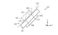
図9に示すように、傾斜壁126に配置される回路基板140は、基板本体141、カートリッジ側端子群142、及び記憶装置143を有している。
基板本体141は、略矩形平板状をしている。カートリッジ側端子群142は、基板本体141の基板表面141aに設けられている。カートリッジ側端子群142は、複数のカートリッジ側端子144で構成されている。本実施形態のカートリッジ側端子群142は、9つの装置側端子69の各々に対応するように9つカートリッジ側端子144で構成されている。カートリッジ側端子144は、装置側端子群65を構成する装置側端子69の各々に対応するように配列されている。各カートリッジ側端子144は、対応する装置側端子69の端子接点70が接触する接触領域145を中央部に有している。As shown in FIG. 9, the
The substrate
記憶装置143は、基板本体141の基板裏面に設けられている。記憶装置143は、インク収容体100に関する情報、例えばインク残量に関する情報等を記憶する。記憶装置143と各カートリッジ側端子144とは電気的に接続されている。 The
回路基板140は、取付溝146と取付孔147とを有する。取付溝146は、+Z方向における基板本体141の端部の中央部分に形成されている。取付孔147は、-Z方向における基板本体141の端部の中央部分に形成されている。回路基板140は、傾斜壁126に形成された第1の取付凸部133に取付溝146が係合し、且つ、傾斜壁126に形成された第2の取付凸部134に取付孔147が係合することにより傾斜壁126に取り付けられる。 The
図10に示すように、回路基板140が傾斜壁126に取り付けられると、接触領域145によって規定される仮想平面150は、装着方向である-Y方向に対して傾斜する。具体的には、仮想平面150は、-Y方向の成分及び+Z方向の成分を含む方向を向くように、換言すれば、仮想平面150の垂線方向が-Y方向の成分及び+Z方向の成分を含むように傾斜する。装置側端子69とカートリッジ側端子144との接点は、仮想平面150上に位置する。各カートリッジ側端子144は、カートリッジ13の装着状態において、装置側端子69が接触領域145に接触することによって装置側端子69と電気的に接続され、液体噴射装置12の制御部38による記憶装置143へのアクセスが可能となる。 As shown in FIG. 10, when the
図8に示すように、端子配置壁部88は、第1の案内部151と第2の案内部152とを有する。第1の案内部151と第2の案内部152は、-Y方向から+Y方向に向かってカートリッジ側端子群142を見たとき、カートリッジ側端子群142を間に挟んだ状態でX方向に互いに向かい合うように設けられている。第1の案内部151及び第2の案内部152は、カートリッジ13の装着過程において、装置側端子群65とカートリッジ側端子群142とが正しく接触する接触位置へとカートリッジ13を案内する。 As shown in FIG. 8 , the terminal
第1の案内部151は、第1の上壁128に形成されている。第1の案内部151は、+Z方向に延びたのちに-Y方向に向かって屈曲する屈曲アーム状をなしている。第1の案内部151は、第1の突部155と第1の延伸部156とを有する。第1の突部155は、第1の上壁128における-X方向の端部と+Y方向の端部とが形成する角部から+Z方向に延びている。第1の突部155は、断面が多角形状、本実施形態では四角形状に形成されている。第1の延伸部156は、+Z方向における第1の突部155の端部から-Y方向に延びている。第1の延伸部156は、断面が多角形状、本実施形態では四角形状に形成されている。多角形状は凸多角形状であるとよい。端子配置壁部88には、第1の上壁128、第1の突部155、及び第1の延伸部156によって、カートリッジ13の装着過程において、図3及び図4に示したホルダー68の第1の凸状部74が差し込まれる第1の差込凹部157が形成される。第1の差込凹部157は、-Y方向に加えて+X方向及び-X方向が開放されている。 A
第1の案内部151は、第1の内側面158と第1の下側面159とを有している。第1の内側面158及び第1の下側面159は、第1のカートリッジ側接触部を構成する。第1の内側面158は、カートリッジ13の装着過程及び装着状態において、ホルダー68の第1のホルダー側壁部71に対して+X方向から接触可能な部位である。第1の内側面158は、Y方向及びZ方向を含む面であり、第1の突部155と第1の延伸部156とに跨がるように、第1の突部155及び第1の延伸部156における-X方向に設けられている。第1のホルダー側壁部71に接触する際、第1の内側面158は、第1の外側面71aに対して面接触する。 The
第1の下側面159は、カートリッジ13の装着過程及び装着状態において、ホルダー68の第1の凸状部74に対して+Z方向から接触可能な部位である。第1の下側面159は、X方向及びY方向を含む面であり、第1の延伸部156における-Z方向に設けられている。第1の凸状部74に接触する際、第1の下側面159は、第1の上側面74aに対して面接触する。 The first
第2の案内部152は、第2の上壁129に形成されている。第2の案内部152は、+Z方向に延びたのちに-Y方向に向かって屈曲する屈曲アーム状をなしている。第2の案内部152は、第2の突部165と第2の延伸部166とを有する。第2の突部165は、第2の上壁129における+X方向の端部と+Y方向の端部とが形成する角部から+Z方向に延びている。第2の突部165は、断面が多角形状、本実施形態では四角形状に形成されている。多角形状は凸多角形状であるとよい。第2の延伸部166は、+Z方向における第2の突部165の端部から-Y方向に延びている。第2の延伸部166は、断面が多角形状、本実施形態では四角形状に形成されている。端子配置壁部88には、第2の上壁129、第2の突部165、及び第2の延伸部166によって、カートリッジ13の装着過程において、図3及び図4に示した第2の凸状部75が-Y方向から差し込まれる第2の差込凹部167が形成される。第2の差込凹部167は、-Y方向に加えて+X方向及び-X方向が開放されている。 A
第2の案内部152は、第2の内側面168と第2の下側面169とを有している。第2の内側面168と第2の下側面169は、第2のカートリッジ側接触部を構成する。第2の内側面168は、カートリッジ13の装着過程及び装着状態において、装置側端子部55のホルダー68の第2のホルダー側壁部72に対して-X方向から接触可能な部位である。第2の内側面168は、Y方向及びZ方向を含む面であり、第2の突部165と第2の延伸部166とに跨がるように、第2の突部165及び第2の延伸部166における+X方向に設けられている。第2のホルダー側壁部72に接触する際、第2の内側面168は、第2の外側面72aに対して面接触する。 The
第2の下側面169は、カートリッジ13の装着過程及び装着状態において、ホルダー68の第2の凸状部75に対して+Z方向から接触可能な部位である。第2の下側面169は、X方向及びY方向を含む面であり、第2の延伸部166における-Z方向に設けられている。第2の凸状部75に接触する際、第2の下側面169は、第2の上側面75aに対して面接触する。 The second
装着過程において、カートリッジ13は、第1の内側面158、第1の下側面159、第2の内側面168、及び第2の下側面169がホルダー68の各部によって案内されながら-Y方向に移動する。これによりカートリッジ13は、装置側端子群65とカートリッジ側端子群142とが正しく接触する接触位置にてカートリッジ装着部28に装着される。なお、こうした端子の接触に関する案内は、第1のカートリッジ側位置決め部111及び第2のカートリッジ側位置決め部112を用いた位置決めが開始されたあとに開始される。 During the mounting process, the
上述した構成のカートリッジ13の作用について説明する。
図11及び図12に示すように、装着状態のカートリッジ13において、第1の案内部151は、第1のホルダー側壁部71に対する+X方向に位置する。第2の案内部152は、第2のホルダー側壁部72に対する-X方向に位置する。装置側端子69に対する+X方向へのカートリッジ側端子144の位置ずれは、第1の内側面158と第1の外側面71aとの接触により規制される。装置側端子69に対する-X方向へのカートリッジ側端子144の位置ずれは、第2の内側面168と第2の外側面72aとの接触により規制される。なお、図12では、第1の延伸部にあたる部分と第2の延伸部にあたる部分にハッチングを施している。The operation of the
As shown in FIGS. 11 and 12 , in the mounted
装着状態のカートリッジ13において、第1の差込凹部157に第1の凸状部74が差し込まれ、また、第2の差込凹部167に第2の凸状部75が差し込まれている。カートリッジ側端子144に対する-Z方向への装置側端子69の位置ずれは、第1の上壁128と第1の凸状部74との接触、及び第2の上壁129と第2の凸状部75との接触により規制される。 In the mounted
傾斜する仮想平面150で装置側端子69とカートリッジ側端子144とが接触する構成では、装置側端子69とカートリッジ側端子144との接触により、ホルダー68を+Z方向へ変位させようとする力Fが装置側端子部55に作用する。すなわち、カートリッジ側端子144に対して装置側端子69を+Z方向へ変位させようとする力Fが装置側端子部55に作用する。こうしたカートリッジ側端子144に対する+Z方向への装置側端子69の位置ずれは、第1の下側面159と第1の上側面74aとの接触、及び第2の下側面169と第2の上側面75aとの接触により規制される。 In the configuration in which the device-
このように装置側端子69に対するカートリッジ側端子144の位置ずれが規制されることで、装置側端子群65の装置側端子69とカートリッジ側端子群142のカートリッジ側端子144とが正しく接触した状態が保持される。 By restricting the positional deviation of the cartridge-
第1実施形態の効果について説明する。
(1)第1の延伸部156は、加圧室99の加圧にともなう第2壁82の変形の影響を第1の上壁128と第1の突部155とを介して受ける。また、第2の延伸部166は、加圧室99の加圧にともなう第2壁82の変形の影響を第2の上壁129と第2の突部165とを介して受ける。そのため、加圧室99を構成する第2壁82の変形の影響を受けにくくなる。すなわち、加圧室99の加圧に起因してケース80が変形したとしても、回路基板140と第1の延伸部156との相対位置、及び回路基板140と第2の延伸部166との相対位置が変化しにくくなる。その結果、装置側端子69とカートリッジ側端子144との接触が正しい位置に保持されやすくなることから、装置側端子69とカートリッジ側端子144との間で接触不良が発生することを抑えることができる。また、装置側端子69とカートリッジ側端子144との間で接触不良が発生することが抑えられることで、例えば、制御部38によるインク残量の演算結果についての誤差を小さくすることができる。Effects of the first embodiment will be described.
(1) The first extending
(2)第1のカートリッジ側接触部の1つである第1の下側面159は、第1の延伸部156の-Z方向に設けられている。第2のカートリッジ側接触部の1つである第2の下側面169は、第2の延伸部166の-Z方向に設けられている。こうした構成によれば、装置側端子69とカートリッジ側端子144とのZ方向の変位を抑えることができる。詳細には、カートリッジ側端子144に対する+Z方向への装置側端子69の変位を抑えることができる。その結果、Z方向の位置ずれに基づく接触不良を抑えることができる。こうした接触不良の抑制は、カートリッジ13の装着過程及び装着状態の双方において得られる。 (2) The first
(3)第1のカートリッジ側接触部の1つである第1の内側面158は、第1の延伸部156の-X方向に設けられている。第2のカートリッジ側接触部の1つである第2の内側面168は、第2の延伸部166の+X方向に設けられている。こうした構成によれば、装置側端子69に対するカートリッジ側端子144のX方向の変位を抑えることができる。その結果、X方向の位置ずれに基づく接触不良を抑えることができる。この接触不良の抑制は、カートリッジ13の装着過程及び装着状態の双方において得られる。 (3) The first
(4)第1のカートリッジ側接触部を構成する第1の内側面158及び第1の下側面159は、第1の延伸部156の-X方向と-Z方向にそれぞれ設けられている。第2のカートリッジ側接触部を構成する第2の内側面168及び第2の下側面169は、第2の延伸部166の+X方向と-Z方向にそれぞれ設けられている。こうした構成によれば、装置側端子69とカートリッジ側端子144とのX方向及びZ方向の位置ずれに基づく接触不良を第1の延伸部156及び第2の延伸部166で抑えることができる。 (4) The first
(5)第1の延伸部156及び第2の延伸部166の断面が四角形状に形成されている。こうした構成によれば、第1の延伸部156及び第2の延伸部166の機械的な強度を高めることができる。その結果、装置側端子69とカートリッジ側端子144との位置ずれを抑える際に第1の延伸部156及び第2の延伸部166の変形を抑えることができる。 (5) The cross sections of the first extending
(6)ホルダー68と第1の延伸部156との接触、及びホルダー68と第2の延伸部166との接触が面接触となるように構成されている。こうした構成によれば、装置側端子69とカートリッジ側端子144との位置ずれを抑える際に第1の延伸部156及び第2の延伸部166の変形を効果的に抑えることができる。 (6) The contact between the
(第2実施形態)
図を参照して、カートリッジ及び液体噴射システムの第2実施形態について説明する。第2実施形態では、第1実施形態と異なる部分について詳細に説明し、第1実施形態と同様の部分については同様の符号を付すことによりその詳細な説明は省略する。(Second embodiment)
A second embodiment of the cartridge and liquid ejection system will be described with reference to the drawings. In the second embodiment, portions different from the first embodiment will be described in detail, and portions similar to those in the first embodiment will be denoted by the same reference numerals, and detailed description thereof will be omitted.
図13に示すように、端子配置壁部88は、第1の案内部171と第2の案内部172とを有する。第1の案内部171と第2の案内部172は、-Y方向から+Y方向に向かってカートリッジ側端子群142を見たとき、カートリッジ側端子群142を間に挟んだ状態でX方向に互いに向かい合うように設けられている。第1の案内部171及び第2の案内部172は、カートリッジ13の装着過程において、装置側端子群65とカートリッジ側端子群142とが正しく接触する接触位置へとカートリッジ13を案内する。 As shown in FIG. 13 , the terminal
第1の案内部171は、第1の上壁128に形成されている。第1の案内部171は、第1の突部173と第1の延伸部174とを有する。第1の突部173は、第1の上壁128における+Y方向の部分から+Z方向に延びている。第1の突部173は、略直方体形状に形成されている。第1の突部173は、第1の前側壁175、第1の接続壁176、及び第1の内側壁177を有する。 A
第1の前側壁175は、X方向及びZ方向を含む壁である。第1の前側壁175は、前壁87の+Y方向、且つ第2壁82の-Y方向に位置する。第1の接続壁176は、X方向及びY方向を含む壁である。第1の接続壁176は、第1の上壁128の+Z方向、且つ第1壁81の-Z方向に位置する。第1の接続壁176は、+Z方向における第1の前側壁175の端部を第2壁82に接続している。第1の内側壁177は、Y方向及びZ方向を含む壁である。第1の内側壁177は、第1の前側壁175における-X方向の端部を第2壁82と接続壁127とに接続している。第1の内側壁177は、第1の接続壁176における-X方向の端部を第2壁82と接続壁127とに接続している。 The first
第1の突部173は、第1の内側面178を有している。第1の内側面178は、第1のカートリッジ側接触部を構成する。第1の内側面178は、カートリッジ13の装着過程及び装着状態において、ホルダー68の第1のホルダー側壁部71に対して+X方向から接触可能な部位である。第1の内側面178は、Y方向及びZ方向を含む面であり、第1の内側壁177に形成されている。第1の内側面178は、第1の突部173における-X方向に設けられている。第1のホルダー側壁部71に接触する際、第1の内側面178は、第1の外側面71aに対して面接触する。 The
第1の延伸部174は、第5壁85よりも第1の前側壁175における-X方向の端部に近い位置に設けられる。第1の延伸部174は、第1の前側壁175から-Y方向に延びている。第1の延伸部174は、断面が円形状に形成されている。端子配置壁部88には、第1の上壁128、第1の突部173、及び第1の延伸部174によって、カートリッジ13の装着過程において、図3及び図4に示したホルダー68の第1の凸状部74が差し込まれる第1の差込凹部179が形成される。第1の差込凹部179は、-Y方向に加えて+X方向及び-X方向が開放されている。 The first extending
第1の延伸部174は、第1の内縁部180と第1の下縁部181とを有している。第1の内縁部180及び第1の下縁部181は、第1のカートリッジ側接触部を構成する。第1の内縁部180は、カートリッジ13の装着過程及び装着状態において、ホルダー68の第1のホルダー側壁部71に対して+X方向から接触可能な部位である。第1の内縁部180は、Y方向に直交する方向における第1の延伸部174の断面において-X方向に位置する縁で構成されている。第1の内縁部180は、Y方向に沿って延びている。第1の内縁部180は、第1の延伸部174における-X方向に設けられている。
第1の下縁部181は、カートリッジ13の装着過程及び装着状態において、ホルダー68の第1の凸状部74に対して+Z方向から接触可能な部位である。第1の下縁部181は、Y方向に直交する方向における第1の延伸部174の断面において-Z方向に位置する縁で構成されている。第1の下縁部181は、Y方向に沿って延びている。第1の下縁部181は、第1の延伸部174における-Z方向に設けられている。 The first
第2の案内部172は、第2の上壁129に形成されている。第2の案内部172は、第2の突部183と第2の延伸部184とを有する。第2の突部183は、第2の上壁129における+Y方向の部分から+Z方向に延びている。第2の突部183は、略直方体形状に形成されている。第2の突部183は、第2の前側壁185、第2の接続壁186、及び第2の内側壁187を有する。 A
第2の前側壁185は、X方向及びZ方向を含む壁である。第2の前側壁185は、前壁87の+Y方向、且つ第2壁82の-Y方向に位置する。第2の接続壁186は、X方向及びY方向を含む壁である。第2の接続壁186は、第2の上壁129の+Z方向、且つ第2壁82の-Z方向に位置する。第2の接続壁186は、+Z方向における第2の前側壁185の端部を第2壁82に接続している。第2の内側壁187は、Y方向及びZ方向を含む壁である。第2の内側壁187は、第2の前側壁185における+X方向の端部を第2壁82と接続壁127とに接続している。第2の内側壁187は、第2の接続壁186における+X方向の端部を第2壁82と接続壁127とに接続している。 A second
第2の突部183は、第2の内側面188を有している。第2の内側面188は、第2のカートリッジ側接触部を構成する。第2の内側面188は、カートリッジ13の装着過程及び装着状態において、ホルダー68の第2のホルダー側壁部72に対して-X方向から接触可能な部位である。第2の内側面188は、Y方向及びZ方向を含む面であり、第2の内側壁187に形成されている。第2の内側面188は、第2の突部183における+X方向に設けられている。第2のホルダー側壁部72に接触する際、第2の内側面188は、第2の外側面72aに対して面接触する。 The
第2の延伸部184は、第6壁86よりも第2の前側壁185における+X方向の端部に近い位置に設けられる。第2の延伸部184は、第2の前側壁185から-Y方向に延びている。第2の延伸部184は、断面が円形状に形成されている。端子配置壁部88には、第2の上壁129、第2の突部183、及び第2の延伸部184によって、カートリッジ13の装着過程において、図3及び図4に示したホルダー68の第2の凸状部75が差し込まれる第2の差込凹部189が形成される。第2の差込凹部189は、-Y方向に加えて+X方向及び-X方向が開放されている。 The second extending
第2の延伸部184は、第2の内縁部190と第2の下縁部191とを有している。第2の内縁部190及び第2の下縁部191は、第2のカートリッジ側接触部を構成する。第2の内縁部190は、カートリッジ13の装着過程及び装着状態において、ホルダー68の第2のホルダー側壁部72に対して-X方向から接触可能な部位である。第2の内縁部190は、Y方向に直交する方向における第2の延伸部184の断面において+X方向に位置する縁で構成されている。第2の内縁部190は、Y方向に沿って延びている。第2の内縁部190は、第2の延伸部184における+X方向に設けられている。
第2の下縁部191は、カートリッジ13の装着過程及び装着状態において、ホルダー68の第2の凸状部75に対して+Z方向から接触可能な部位である。第2の下縁部191は、Y方向に直交する方向における第2の延伸部184の断面において-Z方向に位置する縁で構成されている。第2の下縁部191は、Y方向に沿って延びている。第2の下縁部191は、第2の延伸部184における-Z方向に設けられている。 The second
上述した構成のカートリッジ13の作用について説明する。
図14に示すように、装置側端子69に対する+X方向へのカートリッジ側端子144の位置ずれは、第1の内側面178と第1の外側面71aとの接触、及び第1の内縁部180と第1の外側面71aとの接触により規制される。装置側端子69に対する-X方向へのカートリッジ側端子144の位置ずれは、第2の内側面188と第2の外側面72aとの接触、及び第2の内縁部190と第2の外側面72aとの接触により規制される。また、ホルダー68を+Z方向へ変位させようとする力Fに基づく位置ずれ、すなわちカートリッジ側端子144に対する+Z方向への装置側端子69の位置ずれは、第1の下縁部181と第1の上側面74aとの接触、及び第2の下縁部191と第2の上側面75aとの接触により規制される。なお、図14では、第1の延伸部にあたる部分と第2の延伸部にあたる部分にハッチングを施している。The operation of the
As shown in FIG. 14, the displacement of the cartridge-
第2実施形態の効果について説明する。
(7)第1の延伸部174は、加圧室99の加圧にともなう第2壁82の変形の影響を第1の突部173を介して受ける。また、第2の延伸部184は、加圧室99の加圧にともなう第2壁82の変形の影響を第2の突部183を介して受ける。そのため、加圧室99の加圧に起因してケース80が変形したとしても、回路基板140と第1の延伸部174との相対位置、及び回路基板140と第2の延伸部184との相対位置が変化しにくくなる。その結果、装置側端子69とカートリッジ側端子144との間で接触不良が発生することを抑えることができる。Effects of the second embodiment will be described.
(7) The first extending
(8)第1のカートリッジ側接触部の1つである第1の下縁部181は、第1の延伸部174の-Z方向に設けられている。第2のカートリッジ側接触部の1つである第2の下縁部191は、第2の延伸部184の-Z方向に設けられている。こうした構成によれば、装置側端子69とカートリッジ側端子144とのZ方向の位置ずれに基づく接触不良を抑えることができる。 (8) The first
(9)第1のカートリッジ側接触部の1つである第1の内縁部180は、第1の延伸部174の-X方向に設けられている。第2のカートリッジ側接触部の1つである第2の内縁部190は、第2の延伸部184の+X方向に設けられている。こうした構成によれば、装置側端子69に対するカートリッジ側端子144のX方向の変位を抑えることができる。 (9) The first
(10)第1のカートリッジ側接触部を構成する第1の内縁部180及び第1の下縁部181は、第1の延伸部174の-X方向と-Z方向にそれぞれ設けられている。第2のカートリッジ側接触部を構成する第2の内縁部190及び第2の下縁部191は、第2の延伸部184の+X方向と-Z方向にそれぞれ設けられている。こうした構成によれば、装置側端子69とカートリッジ側端子144とのX方向及びZ方向の位置ずれに基づく接触不良を第1の延伸部174及び第2の延伸部184で抑えることができる。 (10) The first
(11)第1の延伸部174及び第2の延伸部184が断面円形状に形成されている。こうした構成によれば、第1の内縁部180と第1の外側面71aとの接触により、第1の内縁部180に集中的に機械的な負荷が作用したとしても、その機械的な負荷を効率よく分散させることができる。同様に、第2の内縁部190と第2の外側面72aとの接触により、第2の内縁部190に集中的に機械的な負荷が作用したとしても、その機械的な負荷を効率よく分散させることができる。 (11) The first extending
(12)カートリッジ13は、第1のカートリッジ側接触部として、第1の突部173の-X方向に第1の内側面178を有している。こうした構成によれば、第1の外側面71aから第1の延伸部174に付与される機械的な負荷そのものを低減することができる。その結果、装置側端子69とカートリッジ側端子144とのX方向の位置ずれに基づく接触不良を効果的に抑えることができる。 (12) The
(13)カートリッジ13は、第2のカートリッジ側接触部として、第2の突部183の+X方向に第2の内側面188を有している。こうした構成によれば、第2の外側面72aから第2の延伸部184に付与される機械的な負荷そのものを低減することができる。その結果、装置側端子69とカートリッジ側端子144とのX方向の位置ずれに基づく接触不良を効果的に抑えることができる。 (13) The
(第3実施形態)
図15を参照して、カートリッジ及び液体噴射システムの第3実施形態について説明する。(Third embodiment)
A third embodiment of the cartridge and liquid ejection system will be described with reference to FIG.
第3実施形態のカートリッジは、第1実施形態のカートリッジとは、装置側端子69とカートリッジ側端子144とのX方向における位置ずれが第1の突部及び第2の突部のみによって規制される点が異なる。そのため、第3実施形態では、第1実施形態と異なる部分について詳細に説明し、第1実施形態と同様の部分については同様の符号を付すことによりその詳細な説明は省略する。なお、図15では、第1の延伸部にあたる部分と第2の延伸部にあたる部分にハッチングを施している。 The cartridge of the third embodiment differs from the cartridge of the first embodiment in that positional deviation in the X direction between the device-
図15に示すように、端子配置壁部88は、第1の案内部201と第2の案内部202とを有する。第1の案内部201と第2の案内部202は、-Y方向から+Y方向に向かってカートリッジ側端子群142を見たとき、カートリッジ側端子群142を間に挟んだ状態でX方向に互いに向かい合うように設けられている。第1の案内部201及び第2の案内部202は、カートリッジ13の装着過程において、装置側端子群65とカートリッジ側端子群142とが正しく接触する接触位置へとカートリッジ13を案内する。 As shown in FIG. 15, the terminal
第1の案内部201は、第1の突部155と第1の延伸部203とを有する。第1の突部155は、第1の内側面204を有する。第1の内側面204は、Y方向及びZ方向を含む面であり、第1の突部155における-X方向に設けられた第1のカートリッジ側接触部である。第1の延伸部203は、+Z方向における第1の突部155の端部から-Y方向に延びている。第1の延伸部203は、断面が多角形状、本実施形態では四角形状に形成されている。第1の延伸部203は、第1の下側面205と第1の離間内側面206とを有する。第1の下側面205は、カートリッジ13の装着過程及び装着状態において、ホルダー68の第1の凸状部74の一部に対して+Z方向から接触可能な部位である。第1の下側面205は、X方向及びY方向を含む面であり、第1の延伸部203における-Z方向に設けられた第1のカートリッジ側接触部である。第1の離間内側面206は、Y方向に延びる面であり、カートリッジ13の装着過程及び装着状態において、ホルダー68の第1のホルダー側壁部71から離れている面である。 The
第2の案内部202は、第2の突部165と第2の延伸部213とを有する。第2の突部165は、第2の内側面214を有する。第2の内側面214は、Y方向及びZ方向を含む面であり、第2の突部165における-X方向に設けられた第2のカートリッジ側接触部である。第2の延伸部213は、+Z方向における第2の突部165の端部から-Y方向に延びている。第2の延伸部213は、断面が多角形状、本実施形態では四角形状に形成されている。第2の延伸部213は、第2の下側面215と第2の離間内側面216とを有する。第2の下側面215は、カートリッジ13の装着過程及び装着状態において、ホルダー68の第2の凸状部75の一部に対して+Z方向から接触可能な部位である。第2の下側面215は、X方向及びY方向を含む面であり、第2の延伸部213における-Z方向に設けられた第2のカートリッジ側接触部である。第2の離間内側面216は、Y方向に延びる面であり、カートリッジ13の装着過程及び装着状態において、ホルダー68の第2のホルダー側壁部72から離れている面である。 The
上述した構成のカートリッジ13の作用について説明する。
図15に示すように、装置側端子69に対する+X方向へのカートリッジ側端子144の位置ずれは、第1の内側面204と第1の外側面71aとの接触により規制される。装置側端子69に対する-X方向へのカートリッジ側端子144の位置ずれは、第2の内側面214と第2の外側面72aとの接触より規制される。また、ホルダー68を+Z方向へ変位させようとする力Fに基づく位置ずれ、すなわちカートリッジ側端子144に対する+Z方向への装置側端子69の位置ずれは、第1の下側面205と第1の上側面74aとの接触、及び第2の下側面215と第2の上側面75aとの接触により規制される。The operation of the
As shown in FIG. 15, displacement of the cartridge-
第3実施形態の効果について説明する。
(14)加圧室99の加圧に起因してケース80が変形したとしても、回路基板140と第1の延伸部203との相対位置、及び回路基板140と第2の延伸部213との相対位置が変化しにくくなる。その結果、装置側端子69とカートリッジ側端子144との間で接触不良が発生することを抑えることができる。Effects of the third embodiment will be described.
(14) Even if the
(15)第1のカートリッジ側接触部の1つである第1の下側面205は、第1の延伸部203の-Z方向に設けられている。第2のカートリッジ側接触部の1つである第2の下側面215は、第2の延伸部213の-Z方向に設けられている。こうした構成によれば、装置側端子69とカートリッジ側端子144とのZ方向の位置ずれに基づく接触不良を抑えることができる。 (15) A first
(16)第1のカートリッジ側接触部の1つである第1の内側面204は、第1の突部155の-X方向に設けられている。第2のカートリッジ側接触部の1つである第2の内側面214は、第2の突部165の+X方向に設けられている。こうした構成によれば、装置側端子69に対するカートリッジ側端子144のX方向の変位を抑えることができる。 (16) The first
上記実施形態は、以下のように変更して実施することができる。上記実施形態及び以下の変更例は、技術的に矛盾しない範囲で互いに組み合わせて実施することができる。
・第1実施形態において、第1の延伸部156及び第2の延伸部166の断面形状は、四角形状に限られない。第1の延伸部156及び第2の延伸部166の断面形状は、少なくとも一方が他の多角形状であってもよいし、円形状や楕円形状であってもよい。なお、断面形状が多角形状である場合、ホルダー68に面接触するように構成するとよい。The above embodiment can be implemented with the following modifications. The above embodiments and the following modifications can be combined with each other within a technically consistent range.
- In 1st Embodiment, the cross-sectional shape of the 1st extending|stretching
・第2実施形態において、第1の延伸部174及び第2の延伸部184の断面形状は、円形状に限られない。第1の延伸部174及び第2の延伸部184の断面形状は、少なくとも一方が多角形状であってもよいし、楕円形状であってもよい。なお、断面形状が多角形状である場合、ホルダー68に面接触するように構成するとよい。 - In 2nd Embodiment, the cross-sectional shape of the 1st extending|stretching
・第3実施形態において、第1の延伸部203及び第2の延伸部213の断面形状は、四角形状に限られない。第1の延伸部203及び第2の延伸部213の断面形状は、少なくとも一方が他の多角形状であってもよいし、円形状や楕円形状であってもよい。なお、断面形状が多角形状である場合、ホルダー68に面接触するように構成するとよい。 - In 3rd Embodiment, the cross-sectional shape of the 1st extending|stretching
・第1~第3実施形態において、カートリッジ13は、第1の延伸部156,174,203と第2の延伸部166,184,213とに架け渡されて、第1の延伸部156,174,203と第2の延伸部166,184,213とを一体に連結する連結部を有していてもよい。連結部は、カートリッジ13の装着過程及び装着状態においてカートリッジ装着部28に干渉しない位置に設けられる。こうした構成によれば、加圧室99の加圧に起因してケース80が変形したとしても、回路基板140と第1の延伸部156,174,203との相対位置、及び回路基板140と第2の延伸部166,184,213との相対位置がさらに変化しにくくなる。 - In the first to third embodiments, the
・第1及び第2実施形態において、第1のカートリッジ側接触部は、第1の延伸部156,174,203のみに設けられていてもよい。
・第1及び第2実施形態において、第2のカートリッジ側接触部は、第2の延伸部166,184,213のみに設けられていてもよい。- In the first and second embodiments, the first cartridge side contact portion may be provided only in the first extending
- In the first and second embodiments, the second cartridge side contact portion may be provided only in the second extending
・第1~第3実施形態において、複数のカートリッジ側端子144は、回路基板140によって端子配置壁部88に配置される構成に限られない。複数のカートリッジ側端子144は、端子配置壁部88に対して直接形成してもよい。複数のカートリッジ側端子144は、可撓性を有するフィルム状の部材の表面に形成され、該部材が端子配置壁部88に取り付けられることにより端子配置壁部88に配置されてもよい。 - In the first to third embodiments, the plurality of cartridge-
・第1~第3実施形態において、第1の装置側接触部と第1のカートリッジ側接触部との接触は、面接触に限らず、例えば、点接触であってもよいし、複数箇所で接触する構成であってもよい。第2の装置側接触部と第2のカートリッジ側接触部との接触は、面接触に限らず、点接触であってもよいし、複数箇所で接触する構成であってもよい。 ・In the first to third embodiments, the contact between the first device-side contact portion and the first cartridge-side contact portion is not limited to surface contact. A contact configuration may also be used. The contact between the second device-side contact portion and the second cartridge-side contact portion is not limited to surface contact, and may be point contact, or contact at a plurality of locations.
・液体噴射装置12は、インク以外の他の液体を噴射したり吐出したりする液体噴射装置であってもよい。液体噴射装置から微小量の液滴となって吐出される液体の状態としては、粒状、涙状、糸状に尾を引くものも含むものとする。ここでいう液体は、液体噴射装置から噴射させることができるような材料であればよい。例えば、液体は、物質が液相であるときの状態のものであればよく、粘性の高い又は低い液状体、ゾル、ゲル水、その他の無機溶剤、有機溶剤、溶液、液状樹脂、液状金属、金属融液、のような流状体を含むものとする。液体は、物質の一状態としての液体のみならず、顔料や金属粒子などの固形物からなる機能材料の粒子が溶媒に溶解、分散又は混合されたものなども含むものとする。液体の代表的な例としては上記実施形態で説明したようなインクや液晶等が挙げられる。ここで、インクとは一般的な水性インク及び油性インク並びにジェルインク、ホットメルトインク等の各種液体組成物を包含するものとする。液体噴射装置の具体例としては、例えば、液晶ディスプレイ、エレクトロルミネッセンスディスプレイ、面発光ディスプレイ、カラーフィルターの製造等に用いられる電極材や色材等の材料を分散又は溶解のかたちで含む液体を噴射する装置がある。液体噴射装置は、バイオチップ製造に用いられる生体有機物を噴射する装置、精密ピペットとして用いられ試料となる液体を噴射する装置、捺染装置やマイクロディスペンサー等であってもよい。液体噴射装置は、時計やカメラ等の精密機械にピンポイントで潤滑油を噴射する装置、光通信素子等に用いられる微小半球レンズ、光学レンズ、などを形成するために紫外線硬化樹脂等の透明樹脂液を基板上に噴射する装置であってもよい。液体噴射装置は、基板などをエッチングするために酸又はアルカリ等のエッチング液を噴射する装置であってもよい。 - The
上記実施形態及び変更例から把握できる技術的思想について記載する。
カートリッジは、互いに直交する3つの空間軸をそれぞれX軸,Y軸,Z軸とし、前記X軸,Y軸,Z軸に沿った方向をそれぞれX方向,Y方向,Z方向とし、前記X軸,Y軸,Z軸に沿った正の方向をそれぞれ+X方向,+Y方向,+Z方向とし、前記X軸,Y軸,Z軸に沿った負の方向をそれぞれ-X方向,-Y方向,-Z方向とし、前記-Z方向を鉛直方向としたとき、カートリッジに加圧流体を供給する加圧機構と、複数の装置側端子を保持すると共に前記+X方向の側方と前記-X方向の側方にそれぞれ設けられた第1の装置側接触部と第2の装置側接触部とを有するホルダーと、を備えた液体噴射装置に対して+Y方向から-Y方向に向かって移動させることによって装着されるカートリッジであって、複数の前記装置側端子と電気的に接続可能な複数のカートリッジ側端子と、前記加圧流体の供給を受ける加圧室と、複数の前記カートリッジ側端子が配置される端子配置壁部と、前記第1の装置側接触部と接触可能な第1のカートリッジ側接触部と、前記第2の装置側接触部と接触可能な第2のカートリッジ側接触部と、を備え、複数の前記装置側端子と複数の前記カートリッジ側端子とが接触する際に、複数の前記カートリッジ側端子のそれぞれの表面に形成される複数の接点は、前記-Y方向の成分および前記+Z方向の成分を含む方向を向く傾斜面を形成するように配置され、前記加圧室は、前記+Z方向に位置する第1壁と、前記-Y方向に位置する第2壁と、を含む複数の壁を有し、前記端子配置壁部は、前記-Y方向から前記+Y方向に向かって複数の前記カートリッジ側端子を見たとき、複数の前記カートリッジ側端子を間に挟んだ状態で前記X方向に互いに向かい合うように、前記第2壁よりも前記-Y方向に設けられる第1の突部と第2の突部と、前記第1の突部から前記-Y方向に延びる第1の延伸部と、前記第2の突部から前記-Y方向に延びる第2の延伸部と、を含み、前記第1のカートリッジ側接触部は、前記第1の延伸部に設けられ、前記第2のカートリッジ側接触部は、前記第2の延伸部に設けられる。Technical ideas that can be grasped from the above embodiment and modifications will be described.
The cartridge has three spatial axes orthogonal to each other as X, Y and Z axes, and directions along the X, Y and Z axes are respectively X, Y and Z directions. , Y-axis and Z-axis are defined as +X direction, +Y direction and +Z direction, respectively, and negative directions along the X-axis, Y-axis and Z-axis are defined as -X direction, -Y direction and - When the Z direction is defined as the -Z direction and the -Z direction is defined as the vertical direction, a pressurizing mechanism that supplies pressurized fluid to the cartridge, and a plurality of device-side terminals that hold the +X direction side and the -X direction side and a holder having a first device-side contact portion and a second device-side contact portion provided on each side of the liquid ejecting device by moving it from the +Y direction toward the -Y direction. a plurality of cartridge-side terminals electrically connectable to the plurality of apparatus-side terminals; a pressurizing chamber for receiving the supply of the pressurized fluid; and a plurality of the cartridge-side terminals. a terminal arrangement wall portion; a first cartridge side contact portion contactable with the first device side contact portion; and a second cartridge side contact portion contactable with the second device side contact portion. , when the plurality of apparatus-side terminals and the plurality of cartridge-side terminals are brought into contact with each other, the plurality of contacts formed on the surfaces of the plurality of cartridge-side terminals are oriented in the -Y direction and the +Z direction. and the pressure chamber has a first wall positioned in the +Z direction and a second wall positioned in the -Y direction. When the plurality of cartridge-side terminals are viewed from the -Y direction toward the +Y direction, the terminal arrangement wall portion sandwiches the plurality of cartridge-side terminals therebetween in the X direction. a first protrusion and a second protrusion provided in the -Y direction from the second wall so as to face each other; and a first extension extending from the first protrusion in the -Y direction. and a second extending portion extending in the -Y direction from the second projecting portion, wherein the first cartridge side contact portion is provided in the first extending portion, and the second cartridge side contact portion is provided in the first extending portion. A side contact portion is provided on the second extension portion.
上記構成によれば、第1のカートリッジ側接触部が設けられた第1の延伸部は、加圧室の加圧にともなう第2壁の変形の影響を端子配置壁部と第1の突部とを介して受ける。また、第2のカートリッジ側接触部が設けられた第2の延伸部は、加圧室の加圧にともなう第2壁の変形の影響を端子配置壁部と第2の突部とを介して受ける。そのため、加圧室を構成する第2壁が変形したとしても、その変形の影響を受けにくくなる。その結果、加圧室の加圧に起因した第1のカートリッジ側接触部及び第2のカートリッジ側接触部の変形が抑えられることから、カートリッジ側端子と装置側端子との間で接触不良が発生することを抑えることができる。 According to the above configuration, the first extending portion provided with the first cartridge-side contact portion absorbs the influence of the deformation of the second wall due to the pressurization of the pressurizing chamber by the terminal arrangement wall portion and the first projecting portion. and received through Further, the second extending portion provided with the second cartridge-side contact portion absorbs the influence of the deformation of the second wall caused by the pressurization of the pressurizing chamber through the terminal arrangement wall portion and the second projecting portion. receive. Therefore, even if the second wall forming the pressurizing chamber is deformed, it is less likely to be affected by the deformation. As a result, the deformation of the first cartridge-side contact portion and the second cartridge-side contact portion due to the pressurization of the pressurizing chamber is suppressed, so that contact failure occurs between the cartridge-side terminal and the device-side terminal. can refrain from doing
上記カートリッジにおいて、前記第1のカートリッジ側接触部は、前記第1の延伸部の前記-Z方向に設けられ、前記第2のカートリッジ側接触部は、前記第2の延伸部の前記-Z方向に設けられてもよい。 In the cartridge, the first cartridge side contact portion is provided in the -Z direction of the first extending portion, and the second cartridge side contact portion is provided in the -Z direction of the second extending portion. may be provided in
上記構成によれば、カートリッジ側端子と装置側端子との間においてZ方向で接触不良が発生することを抑えることができる。
上記カートリッジにおいて、前記第1のカートリッジ側接触部は、前記第1の延伸部の前記-X方向に設けられ、前記第2のカートリッジ側接触部は、前記第2の延伸部の前記+X方向に設けられてもよい。According to the above configuration, it is possible to suppress the occurrence of poor contact in the Z direction between the cartridge-side terminals and the device-side terminals.
In the cartridge, the first cartridge-side contact portion is provided in the -X direction of the first extending portion, and the second cartridge-side contact portion is provided in the +X direction of the second extending portion. may be provided.
上記構成によれば、カートリッジ側端子と装置側端子との間においてX方向で接触不良が発生することを抑えることができる。
上記カートリッジにおいて、前記第1のカートリッジ側接触部は、前記第1の延伸部の前記-X方向と前記-Z方向にそれぞれ設けられ、前記第2のカートリッジ側接触部は、前記第2の延伸部の前記+X方向と前記-Z方向にそれぞれ設けられてもよい。According to the above configuration, it is possible to suppress the occurrence of poor contact in the X direction between the cartridge-side terminals and the device-side terminals.
In the cartridge, the first cartridge-side contact portion is provided in the -X direction and the -Z direction of the first extending portion, respectively, and the second cartridge-side contact portion is provided in the second extending portion. may be provided in the +X direction and the -Z direction of the part, respectively.
上記構成によれば、カートリッジ側端子と装置側端子との間においてX方向及びZ方向で接触不良が発生することを抑えることができる。
上記カートリッジにおいて、前記第1の延伸部の断面が円形または多角形で構成され、前記第2の延伸部の断面が円形または多角形で構成されていてもよい。According to the above configuration, it is possible to suppress the occurrence of poor contact in the X direction and the Z direction between the cartridge-side terminals and the device-side terminals.
In the above cartridge, the cross section of the first extending portion may be circular or polygonal, and the cross section of the second extending portion may be circular or polygonal.
上記構成によれば、加圧室の加圧に起因した第1のカートリッジ側接触部及び第2のカートリッジ側接触部の変形が効果的に抑えられることから、カートリッジ側端子と装置側端子との間で接触不良が発生することを効果的に抑えることができる。 According to the above configuration, the deformation of the first cartridge-side contact portion and the second cartridge-side contact portion due to the pressurization of the pressurizing chamber can be effectively suppressed. It is possible to effectively suppress the occurrence of poor contact between them.
カートリッジは、互いに直交する3つの空間軸をそれぞれX軸,Y軸,Z軸とし、前記X軸,Y軸,Z軸に沿った方向をそれぞれX方向,Y方向,Z方向とし、前記X軸,Y軸,Z軸に沿った正の方向をそれぞれ+X方向,+Y方向,+Z方向とし、前記X軸,Y軸,Z軸に沿った負の方向をそれぞれ-X方向,-Y方向,-Z方向とし、前記-Z方向を鉛直方向としたとき、カートリッジに加圧流体を供給する加圧機構と、複数の装置側端子を保持すると共に前記+X方向の側方と前記-X方向の側方にそれぞれ設けられた第1の装置側接触部と第2の装置側接触部とを有するホルダーと、を備えた液体噴射装置に対して+Y方向から-Y方向に向かって移動させることによって装着されるカートリッジであって、複数の前記装置側端子と電気的に接続可能な複数のカートリッジ側端子と、前記加圧流体の供給を受ける加圧室と、複数の前記カートリッジ側端子が配置される端子配置壁部と、前記第1の装置側接触部と接触可能な第1のカートリッジ側接触部と、前記第2の装置側接触部と接触可能な第2のカートリッジ側接触部と、を備え、複数の前記装置側端子と複数の前記カートリッジ側端子とが接触する際に、複数の前記カートリッジ側端子のそれぞれの表面に形成される複数の接点は、前記-Y方向の成分および前記+Z方向の成分を含む方向を向く傾斜面を形成するように配置され、前記加圧室は、前記+Z方向に位置する第1壁と、前記-Y方向に位置する第2壁と、を含む複数の壁を有し、前記端子配置壁部は、前記-Y方向から前記+Y方向に向かって複数の前記カートリッジ側端子を見たとき、複数の前記カートリッジ側端子を間に挟んだ状態で前記X方向に互いに向かい合うように、前記第2壁よりも前記-Y方向に設けられる第1の突部と第2の突部と、前記第1の突部から前記-Y方向に延びる第1の延伸部と、前記第2の突部から前記-Y方向に延びる第2の延伸部と、を含み、前記第1のカートリッジ側接触部は、前記第1の突部の前記-X方向と、前記第1の延伸部の前記-Z方向と、に設けられ、前記第2のカートリッジ側接触部は、前記第2の突部の前記+X方向と、前記第2の延伸部の前記-Z方向と、に設けられる。 The cartridge has three spatial axes orthogonal to each other as X, Y and Z axes, and directions along the X, Y and Z axes are respectively X, Y and Z directions. , Y-axis and Z-axis are defined as +X direction, +Y direction and +Z direction, respectively, and negative directions along the X-axis, Y-axis and Z-axis are defined as -X direction, -Y direction and - When the Z direction is defined as the -Z direction and the -Z direction is defined as the vertical direction, a pressurizing mechanism that supplies pressurized fluid to the cartridge, and a plurality of device-side terminals that hold the +X direction side and the -X direction side and a holder having a first device-side contact portion and a second device-side contact portion provided on each side of the liquid ejecting device by moving it from the +Y direction toward the -Y direction. a plurality of cartridge-side terminals electrically connectable to the plurality of apparatus-side terminals; a pressurizing chamber for receiving the supply of the pressurized fluid; and a plurality of the cartridge-side terminals. a terminal arrangement wall portion; a first cartridge side contact portion contactable with the first device side contact portion; and a second cartridge side contact portion contactable with the second device side contact portion. , when the plurality of apparatus-side terminals and the plurality of cartridge-side terminals are brought into contact with each other, the plurality of contacts formed on the surfaces of the plurality of cartridge-side terminals are oriented in the -Y direction and the +Z direction. and the pressure chamber has a first wall positioned in the +Z direction and a second wall positioned in the -Y direction. When the plurality of cartridge-side terminals are viewed from the -Y direction toward the +Y direction, the terminal arrangement wall portion sandwiches the plurality of cartridge-side terminals therebetween in the X direction. a first protrusion and a second protrusion provided in the -Y direction from the second wall so as to face each other; and a first extension extending from the first protrusion in the -Y direction. and a second extending portion extending in the -Y direction from the second protrusion, wherein the first cartridge-side contact portion includes the -X direction of the first protrusion and the second extension portion. and the -Z direction of the first extending portion, and the second cartridge side contact portion is provided in the +X direction of the second protrusion, the -Z direction of the second extending portion, provided in
上記構成によれば、カートリッジ側端子と装置側端子との間におけるX方向での接触不良が発生することを第1の突部及び第2の突部で抑えることができる。カートリッジ側端子と装置側端子との間におけるZ方向での接触不良が発生することを第1の延伸部及び第2の延伸部で抑えることができる。 According to the above configuration, the first protrusion and the second protrusion can suppress the occurrence of contact failure in the X direction between the cartridge-side terminal and the device-side terminal. The first extending portion and the second extending portion can suppress the occurrence of poor contact in the Z direction between the cartridge-side terminal and the device-side terminal.
液体噴射システムは、互いに直交する3つの空間軸をそれぞれX軸,Y軸,Z軸とし、前記X軸,Y軸,Z軸に沿った方向をそれぞれX方向,Y方向,Z方向とし、前記X軸,Y軸,Z軸に沿った正の方向をそれぞれ+X方向,+Y方向,+Z方向とし、前記X軸,Y軸,Z軸に沿った負の方向をそれぞれ-X方向,-Y方向,-Z方向とし、前記-Z方向を鉛直方向としたとき、カートリッジに加圧流体を供給する加圧機構と、複数の装置側端子を保持すると共に前記+X方向の側方と前記-X方向の側方にそれぞれ設けられた第1の装置側接触部と第2の装置側接触部とを有するホルダーと、を備えた液体噴射装置と、前記液体噴射装置に対して+Y方向から-Y方向に向かって移動させることによって装着されるカートリッジと、を備えた液体噴射システムであって、前記カートリッジが上述したカートリッジである。この構成によれば、上述したカートリッジと同様の効果を得ることができる。 In the liquid jet system, the three spatial axes orthogonal to each other are the X-axis, the Y-axis, and the Z-axis, respectively, and the directions along the X-axis, the Y-axis, and the Z-axis are the X-direction, the Y-direction, and the Z-direction, respectively. The positive directions along the X-, Y-, and Z-axes are the +X-, +Y-, and +Z-directions, respectively, and the negative directions along the X-, Y-, and Z-axes are the -X and -Y directions, respectively. , the -Z direction, and when the -Z direction is taken as a vertical direction, a pressurizing mechanism for supplying a pressurized fluid to the cartridge, a plurality of device-side terminals are held, and laterally in the +X direction and in the -X direction. a holder having a first device-side contact portion and a second device-side contact portion provided on each side of the liquid ejecting device; a cartridge mounted by moving toward the cartridge, wherein the cartridge is the cartridge described above. According to this configuration, it is possible to obtain the same effect as the cartridge described above.
F…力、P…記録用紙、11…液体噴射システム、12…液体噴射装置、13…カートリッジ、14…本体ケース、15…支持台、16…ガイド軸、17…キャリッジ、18…駆動プーリー、19…従動プーリー、20…キャリッジモーター、21…タイミングベルト、25…液体噴射ヘッド、26…バルブユニット、28…カートリッジ装着部、29…加圧機構、30…インク流路、31…加圧ポンプ、32…共通流路、33…分配器、34…分配流路、35…バルブ、36a…第1分岐流路、36b…第2分岐流路、36c…第3分岐流路、38…制御部、41…装置側前壁部、42…装置側側壁部、43…装置側側壁部、44…装置側側壁部、45…装置側側壁部、46…カートリッジ収容室、47…装着口、48…スロット、50…インク導入機構、51…インク加圧部、52…第1の装置側位置決め部、53…第2の装置側位置決め部、54…装置側規制部、55…装置側端子部、56…第1の撹拌用加圧部、57…第2の撹拌用加圧部、60…インク導入部、61…カバー部、62…ピン、65…装置側端子群、66…端子台、66a…端子台表面、67…コネクター基板、67a…コネクター表面、68…ホルダー、69…装置側端子、70…端子接点、71…第1のホルダー側壁部、71a…第1の外側面、72…第2のホルダー側壁部、72a…第2の外側面、74…第1の凸状部、74a…第1の上側面、75…第2の凸状部、75a…第2の上側面、76…第1のテーパー部、77…第2のテーパー部、78…第1係合部、79…第2係合部、80…ケース、81…第1壁、82…第2壁、83…第3壁、84…第4壁、85…第5壁、86…第6壁、87…前壁、88…端子配置壁部、91…第1のケース部材、92…封止部材、93…インク収容部、94…第1の撹拌部、95…第2の撹拌部、96…第2のケース部材、98…開口、99…加圧室、100…インク収容体、101…インク導出部、102…導出開口、103…第1の撹拌部材、104…第1の流体流通路、104A…他端、105…第2の撹拌部材、106…第2の流体流通路、106A…他端、110…導出空間形成部、111…第1のカートリッジ側位置決め部、112…第2のカートリッジ側位置決め部、113…カートリッジ側規制部、115…凹部、115a…底壁、116…インク用流体流通部、117…第1の撹拌用流体流通部、118…第2の撹拌用流体流通部、126…傾斜壁、127…接続壁、128…第1の上壁、129…第2の上壁、131…第1の内側壁、132…第2の内側壁、133…第1の取付凸部、134…第2の取付凸部、135…基板用凹部、140…回路基板、141…基板本体、141a…基板表面、142…カートリッジ側端子群、143…記憶装置、144…カートリッジ側端子、145…接触領域、146…取付溝、147…取付孔、150…仮想平面、151…第1の案内部、152…第2の案内部、155…第1の突部、156…第1の延伸部、157…第1の差込凹部、158…第1の内側面、159…第1の下側面、165…第2の突部、166…第2の延伸部、167…第2の差込凹部、168…第2の内側面、169…第2の下側面、171…第1の案内部、172…第2の案内部、173…第1の突部、174…第1の延伸部、175…第1の前側壁、176…第1の接続壁、177…第1の内側壁、178…第1の内側面、179…第1の差込凹部、180…第1の内縁部、181…第1の下縁部、183…第2の突部、184…第2の延伸部、185…第2の前側壁、186…第2の接続壁、187…第2の内側壁、188…第2の内側面、189…第2の差込凹部、190…第2の内縁部、191…第2の下縁部、201…第1の案内部、202…第2の案内部、203…第1の延伸部、204…第1の内側面、205…第1の下側面、206…第1の離間内側面、213…第2の延伸部、214…第2の内側面、215…第2の下側面、216…第2の離間内側面、250…カートリッジ、251…ケース、252…基板用凹部、253…回路基板、254…側壁部、255…側壁部、256…カートリッジ側端子、257…表面、258…前面、259…位置決め溝、260…位置決め溝。 F... force, P... recording paper, 11... liquid ejection system, 12... liquid ejection device, 13... cartridge, 14... body case, 15... support base, 16... guide shaft, 17... carriage, 18... drive pulley, 19 Driven
Claims (7)
Translated fromJapanese前記X軸,Y軸,Z軸に沿った方向をそれぞれX方向,Y方向,Z方向とし、
前記X軸,Y軸,Z軸に沿った正の方向をそれぞれ+X方向,+Y方向,+Z方向とし、
前記X軸,Y軸,Z軸に沿った負の方向をそれぞれ-X方向,-Y方向,-Z方向とし、
前記-Z方向を鉛直方向としたとき、
カートリッジに加圧流体を供給する加圧機構と、複数の装置側端子を保持すると共に前記+X方向の側方と前記-X方向の側方にそれぞれ設けられた第1の装置側接触部と第2の装置側接触部とを有するホルダーと、を備えた液体噴射装置に対して+Y方向から-Y方向に向かって移動させることによって装着されるカートリッジであって、
複数の前記装置側端子と電気的に接続可能な複数のカートリッジ側端子と、
前記加圧流体の供給を受ける加圧室と、
複数の前記カートリッジ側端子が配置される端子配置壁部と、
前記第1の装置側接触部と接触可能な第1のカートリッジ側接触部と、
前記第2の装置側接触部と接触可能な第2のカートリッジ側接触部と、
を備え、
複数の前記装置側端子と複数の前記カートリッジ側端子とが接触する際に、複数の前記カートリッジ側端子のそれぞれの表面に形成される複数の接点は、前記-Y方向の成分および前記+Z方向の成分を含む方向を向く傾斜面を形成するように配置され、
前記加圧室は、
前記+Z方向に位置する第1壁と、
前記-Y方向に位置する第2壁と、
を含む複数の壁を有し、
前記端子配置壁部は、
前記-Y方向から前記+Y方向に向かって複数の前記カートリッジ側端子を見たとき、複数の前記カートリッジ側端子を間に挟んだ状態で前記X方向に互いに向かい合うように、前記第2壁よりも前記-Y方向に設けられる第1の突部と第2の突部と、
前記第1の突部から前記-Y方向に延びる第1の延伸部と、
前記第2の突部から前記-Y方向に延びる第2の延伸部と、を含み、
前記第1のカートリッジ側接触部は、前記第1の延伸部に設けられ、
前記第2のカートリッジ側接触部は、前記第2の延伸部に設けられる、
ことを特徴とするカートリッジ。Let the three spatial axes orthogonal to each other be the X-axis, the Y-axis, and the Z-axis, respectively,
Let the directions along the X-axis, Y-axis, and Z-axis be the X-direction, the Y-direction, and the Z-direction, respectively,
The positive directions along the X-axis, Y-axis, and Z-axis are respectively +X direction, +Y direction, and +Z direction,
The negative directions along the X-axis, Y-axis, and Z-axis are respectively -X direction, -Y direction, and -Z direction,
When the -Z direction is the vertical direction,
a pressurizing mechanism that supplies a pressurized fluid to the cartridge; a first device-side contact portion that holds a plurality of device-side terminals and is provided on the side in the +X direction and the side in the -X direction; 2 device-side contact portions;
a plurality of cartridge-side terminals electrically connectable to the plurality of device-side terminals;
a pressurization chamber that receives the supply of the pressurized fluid;
a terminal arrangement wall on which the plurality of cartridge-side terminals are arranged;
a first cartridge-side contact portion contactable with the first device-side contact portion;
a second cartridge-side contact portion contactable with the second device-side contact portion;
with
When the plurality of apparatus-side terminals and the plurality of cartridge-side terminals are brought into contact with each other, the plurality of contacts formed on the surfaces of the plurality of cartridge-side terminals are the components of the −Y direction and the +Z direction. arranged to form an inclined surface facing in the direction containing the component;
The pressure chamber is
a first wall positioned in the +Z direction;
a second wall located in the -Y direction;
having multiple walls containing
The terminal arrangement wall portion
When viewed from the -Y direction to the +Y direction, the plurality of cartridge side terminals are positioned closer to each other than the second wall so as to face each other in the X direction with the plurality of cartridge side terminals sandwiched therebetween. a first protrusion and a second protrusion provided in the -Y direction;
a first extending portion extending in the -Y direction from the first protrusion;
a second extending portion extending in the -Y direction from the second protrusion,
The first cartridge-side contact portion is provided on the first extending portion,
wherein the second cartridge-side contact portion is provided on the second extending portion;
A cartridge characterized by:
前記第2のカートリッジ側接触部は、前記第2の延伸部の前記-Z方向に設けられる、
ことを特徴とする請求項1に記載のカートリッジ。the first cartridge-side contact portion is provided in the -Z direction of the first extending portion;
the second cartridge side contact portion is provided in the -Z direction of the second extending portion;
The cartridge according to claim 1, characterized in that:
前記第2のカートリッジ側接触部は、前記第2の延伸部の前記+X方向に設けられる、
ことを特徴とする請求項1に記載のカートリッジ。the first cartridge side contact portion is provided in the -X direction of the first extending portion;
wherein the second cartridge-side contact portion is provided in the +X direction of the second extending portion;
The cartridge according to claim 1, characterized in that:
前記第2のカートリッジ側接触部は、前記第2の延伸部の前記+X方向と前記-Z方向にそれぞれ設けられる、
ことを特徴とする請求項1に記載のカートリッジ。the first cartridge side contact portion is provided in each of the -X direction and the -Z direction of the first extending portion;
The second cartridge-side contact portion is provided in each of the +X direction and the -Z direction of the second extending portion,
The cartridge according to claim 1, characterized in that:
前記第2の延伸部の断面が円形または多角形で構成されている、
ことを特徴とする請求項1から請求項4のいずれか一項に記載のカートリッジ。The cross section of the first extending portion is circular or polygonal,
The second extension has a circular or polygonal cross-section,
5. The cartridge according to any one of claims 1 to 4, characterized in that:
前記X軸,Y軸,Z軸に沿った方向をそれぞれX方向,Y方向,Z方向とし、
前記X軸,Y軸,Z軸に沿った正の方向をそれぞれ+X方向,+Y方向,+Z方向とし、
前記X軸,Y軸,Z軸に沿った負の方向をそれぞれ-X方向,-Y方向,-Z方向とし、
前記-Z方向を鉛直方向としたとき、
カートリッジに加圧流体を供給する加圧機構と、複数の装置側端子を保持すると共に前記+X方向の側方と前記-X方向の側方にそれぞれ設けられた第1の装置側接触部と第2の装置側接触部とを有するホルダーと、を備えた液体噴射装置に対して+Y方向から-Y方向に向かって移動させることによって装着されるカートリッジであって、
複数の前記装置側端子と電気的に接続可能な複数のカートリッジ側端子と、
前記加圧流体の供給を受ける加圧室と、
複数の前記カートリッジ側端子が配置される端子配置壁部と、
前記第1の装置側接触部と接触可能な第1のカートリッジ側接触部と、
前記第2の装置側接触部と接触可能な第2のカートリッジ側接触部と、
を備え、
複数の前記装置側端子と複数の前記カートリッジ側端子とが接触する際に、複数の前記カートリッジ側端子のそれぞれの表面に形成される複数の接点は、前記-Y方向の成分および前記+Z方向の成分を含む方向を向く傾斜面を形成するように配置され、
前記加圧室は、
前記+Z方向に位置する第1壁と、
前記-Y方向に位置する第2壁と、
を含む複数の壁を有し、
前記端子配置壁部は、
前記-Y方向から前記+Y方向に向かって複数の前記カートリッジ側端子を見たとき、複数の前記カートリッジ側端子を間に挟んだ状態で前記X方向に互いに向かい合うように、前記第2壁よりも前記-Y方向に設けられる第1の突部と第2の突部と、
前記第1の突部から前記-Y方向に延びる第1の延伸部と、
前記第2の突部から前記-Y方向に延びる第2の延伸部と、を含み、
前記第1のカートリッジ側接触部は、前記第1の突部の前記-X方向と、前記第1の延伸部の前記-Z方向と、に設けられ、
前記第2のカートリッジ側接触部は、前記第2の突部の前記+X方向と、前記第2の延伸部の前記-Z方向と、に設けられる、
ことを特徴とするカートリッジ。Let the three spatial axes orthogonal to each other be the X-axis, the Y-axis, and the Z-axis, respectively,
Let the directions along the X-axis, Y-axis, and Z-axis be the X-direction, the Y-direction, and the Z-direction, respectively,
The positive directions along the X-axis, Y-axis, and Z-axis are respectively +X direction, +Y direction, and +Z direction,
The negative directions along the X-axis, Y-axis, and Z-axis are respectively -X direction, -Y direction, and -Z direction,
When the -Z direction is the vertical direction,
a pressurizing mechanism that supplies a pressurized fluid to the cartridge; a first device-side contact portion that holds a plurality of device-side terminals and is provided on the side in the +X direction and the side in the -X direction; 2 device-side contact portions;
a plurality of cartridge-side terminals electrically connectable to the plurality of device-side terminals;
a pressurization chamber that receives the supply of the pressurized fluid;
a terminal arrangement wall on which the plurality of cartridge-side terminals are arranged;
a first cartridge-side contact portion contactable with the first device-side contact portion;
a second cartridge-side contact portion contactable with the second device-side contact portion;
with
When the plurality of device-side terminals and the plurality of cartridge-side terminals are brought into contact with each other, the plurality of contacts formed on the surfaces of the plurality of cartridge-side terminals are the -Y direction component and the +Z direction component. arranged to form an inclined surface facing in the direction containing the component;
The pressure chamber is
a first wall positioned in the +Z direction;
a second wall positioned in the -Y direction;
having multiple walls containing
The terminal arrangement wall portion
When viewed from the -Y direction to the +Y direction, the plurality of cartridge side terminals are positioned closer to each other than the second wall so as to face each other in the X direction with the plurality of cartridge side terminals sandwiched therebetween. a first protrusion and a second protrusion provided in the -Y direction;
a first extending portion extending in the -Y direction from the first protrusion;
a second extending portion extending in the -Y direction from the second protrusion,
the first cartridge side contact portion is provided in the -X direction of the first protrusion and in the -Z direction of the first extending portion;
the second cartridge-side contact portion is provided in the +X direction of the second protrusion and in the -Z direction of the second extending portion;
A cartridge characterized by:
前記X軸,Y軸,Z軸に沿った方向をそれぞれX方向,Y方向,Z方向とし、
前記X軸,Y軸,Z軸に沿った正の方向をそれぞれ+X方向,+Y方向,+Z方向とし、
前記X軸,Y軸,Z軸に沿った負の方向をそれぞれ-X方向,-Y方向,-Z方向とし、
前記-Z方向を鉛直方向としたとき、
カートリッジに加圧流体を供給する加圧機構と、複数の装置側端子を保持すると共に前記+X方向の側方と前記-X方向の側方にそれぞれ設けられた第1の装置側接触部と第2の装置側接触部とを有するホルダーと、を備えた液体噴射装置と、
前記液体噴射装置に対して+Y方向から-Y方向に向かって移動させることによって装着されるカートリッジと、を備えた液体噴射システムであって、
前記カートリッジが請求項1から請求項6のいずれか一項に記載のカートリッジである
ことを特徴とする液体噴射システム。
Let the three spatial axes orthogonal to each other be the X-axis, the Y-axis, and the Z-axis, respectively,
Let the directions along the X-axis, Y-axis, and Z-axis be the X-direction, the Y-direction, and the Z-direction, respectively,
The positive directions along the X-axis, Y-axis, and Z-axis are respectively +X direction, +Y direction, and +Z direction,
The negative directions along the X-axis, Y-axis, and Z-axis are respectively -X direction, -Y direction, and -Z direction,
When the -Z direction is the vertical direction,
a pressurizing mechanism that supplies a pressurized fluid to the cartridge; a first device-side contact portion that holds a plurality of device-side terminals and is provided on the side in the +X direction and the side in the -X direction; a holder having two device-side contact portions;
a cartridge mounted by moving the liquid ejecting device from the +Y direction toward the -Y direction,
A liquid ejection system, wherein the cartridge is the cartridge according to any one of claims 1 to 6.
Priority Applications (3)
| Application Number | Priority Date | Filing Date | Title |
|---|---|---|---|
| JP2019012824AJP7183823B2 (en) | 2019-01-29 | 2019-01-29 | Cartridge and liquid injection system |
| CN202010073281.9ACN111483231B (en) | 2019-01-29 | 2020-01-22 | Container and liquid ejecting system |
| US16/774,378US11014369B2 (en) | 2019-01-29 | 2020-01-28 | Cartridge and liquid ejecting system |
Applications Claiming Priority (1)
| Application Number | Priority Date | Filing Date | Title |
|---|---|---|---|
| JP2019012824AJP7183823B2 (en) | 2019-01-29 | 2019-01-29 | Cartridge and liquid injection system |
Publications (2)
| Publication Number | Publication Date |
|---|---|
| JP2020121415A JP2020121415A (en) | 2020-08-13 |
| JP7183823B2true JP7183823B2 (en) | 2022-12-06 |
Family
ID=71733288
Family Applications (1)
| Application Number | Title | Priority Date | Filing Date |
|---|---|---|---|
| JP2019012824AActiveJP7183823B2 (en) | 2019-01-29 | 2019-01-29 | Cartridge and liquid injection system |
Country Status (3)
| Country | Link |
|---|---|
| US (1) | US11014369B2 (en) |
| JP (1) | JP7183823B2 (en) |
| CN (1) | CN111483231B (en) |
Families Citing this family (4)
| Publication number | Priority date | Publication date | Assignee | Title |
|---|---|---|---|---|
| CN214606596U (en)* | 2020-09-21 | 2021-11-05 | 珠海纳思达企业管理有限公司 | An ink quantity detection mechanism, an ink cartridge and a printer |
| JP7533069B2 (en) | 2020-09-25 | 2024-08-14 | セイコーエプソン株式会社 | Cartridge, printing system, and printing device |
| CN115871340B (en) | 2022-07-26 | 2025-09-12 | 珠海纳思达企业管理有限公司 | ink cartridge |
| JP2025024262A (en)* | 2023-08-07 | 2025-02-20 | キヤノン株式会社 | Ink container and recording device |
Citations (6)
| Publication number | Priority date | Publication date | Assignee | Title |
|---|---|---|---|---|
| JP2005212379A (en) | 2004-01-30 | 2005-08-11 | Seiko Epson Corp | Liquid container |
| US20070020961A1 (en) | 2005-07-20 | 2007-01-25 | Yi-Tse Ho | Electrical connector |
| JP2014240182A (en) | 2013-05-15 | 2014-12-25 | セイコーエプソン株式会社 | Cartridge, and print material supply system |
| JP2016187876A (en) | 2015-03-30 | 2016-11-04 | セイコーエプソン株式会社 | Cartridge, cartridge unit and liquid injection system |
| JP2018118522A (en) | 2012-01-13 | 2018-08-02 | セイコーエプソン株式会社 | Cartridge, printing material supply system, printing apparatus, liquid container, printing system, and terminal connection structure |
| EP3412463A1 (en) | 2016-02-05 | 2018-12-12 | Zhuhai Ninestar Management Co., Ltd. | Ink cartridge |
Family Cites Families (7)
| Publication number | Priority date | Publication date | Assignee | Title |
|---|---|---|---|---|
| JP5521604B2 (en)* | 2010-02-12 | 2014-06-18 | セイコーエプソン株式会社 | Terminal connection structure, liquid container, and method for assembling liquid container |
| CN203401816U (en)* | 2013-07-19 | 2014-01-22 | 珠海纳思达企业管理有限公司 | Ink-jet ink box |
| JP6311251B2 (en)* | 2013-09-20 | 2018-04-18 | セイコーエプソン株式会社 | Liquid container |
| WO2015093008A1 (en)* | 2013-12-18 | 2015-06-25 | セイコーエプソン株式会社 | Liquid supply unit |
| JP2017056706A (en)* | 2015-09-18 | 2017-03-23 | セイコーエプソン株式会社 | Terminal connection and cartridge |
| JP7000688B2 (en)* | 2017-02-28 | 2022-01-19 | セイコーエプソン株式会社 | Liquid containment |
| JP6409947B2 (en)* | 2017-11-29 | 2018-10-24 | セイコーエプソン株式会社 | Liquid supply unit |
- 2019
- 2019-01-29JPJP2019012824Apatent/JP7183823B2/enactiveActive
- 2020
- 2020-01-22CNCN202010073281.9Apatent/CN111483231B/enactiveActive
- 2020-01-28USUS16/774,378patent/US11014369B2/enactiveActive
Patent Citations (6)
| Publication number | Priority date | Publication date | Assignee | Title |
|---|---|---|---|---|
| JP2005212379A (en) | 2004-01-30 | 2005-08-11 | Seiko Epson Corp | Liquid container |
| US20070020961A1 (en) | 2005-07-20 | 2007-01-25 | Yi-Tse Ho | Electrical connector |
| JP2018118522A (en) | 2012-01-13 | 2018-08-02 | セイコーエプソン株式会社 | Cartridge, printing material supply system, printing apparatus, liquid container, printing system, and terminal connection structure |
| JP2014240182A (en) | 2013-05-15 | 2014-12-25 | セイコーエプソン株式会社 | Cartridge, and print material supply system |
| JP2016187876A (en) | 2015-03-30 | 2016-11-04 | セイコーエプソン株式会社 | Cartridge, cartridge unit and liquid injection system |
| EP3412463A1 (en) | 2016-02-05 | 2018-12-12 | Zhuhai Ninestar Management Co., Ltd. | Ink cartridge |
Also Published As
| Publication number | Publication date |
|---|---|
| JP2020121415A (en) | 2020-08-13 |
| CN111483231B (en) | 2022-09-13 |
| US11014369B2 (en) | 2021-05-25 |
| US20200238719A1 (en) | 2020-07-30 |
| CN111483231A (en) | 2020-08-04 |
Similar Documents
| Publication | Publication Date | Title |
|---|---|---|
| JP7183823B2 (en) | Cartridge and liquid injection system | |
| US10414164B2 (en) | Cartridge, cartridge unit, and liquid ejection system | |
| JP6476551B2 (en) | Cartridge and printing material supply system | |
| EP3144154B1 (en) | Terminal connection assembly and cartridge | |
| CN107878038B (en) | Containers and Connectors | |
| CN111356591B (en) | Container and liquid ejecting apparatus | |
| JP6651846B2 (en) | Liquid supply unit, liquid ejection system | |
| WO2017115582A1 (en) | Liquid supply unit | |
| JP2016049772A (en) | Liquid supply unit | |
| JP2017056686A (en) | Terminal connection section and cartridge | |
| WO2017090374A1 (en) | Liquid supply unit and liquid ejection device | |
| CN106004059B (en) | Cartridge and Liquid Injection System | |
| JP6511910B2 (en) | Cartridge and liquid injection system | |
| JP7131421B2 (en) | Cartridge and liquid injection system | |
| US12330426B2 (en) | Cartridge | |
| JP6915705B2 (en) | Liquid supply unit, liquid injection system | |
| JP2017056705A (en) | Terminal connection section and cartridge | |
| JP6536267B2 (en) | Liquid supply unit | |
| CN105751705A (en) | Liquid Supply Unit |
Legal Events
| Date | Code | Title | Description |
|---|---|---|---|
| A621 | Written request for application examination | Free format text:JAPANESE INTERMEDIATE CODE: A621 Effective date:20211112 | |
| A977 | Report on retrieval | Free format text:JAPANESE INTERMEDIATE CODE: A971007 Effective date:20220928 | |
| TRDD | Decision of grant or rejection written | ||
| A01 | Written decision to grant a patent or to grant a registration (utility model) | Free format text:JAPANESE INTERMEDIATE CODE: A01 Effective date:20221025 | |
| A61 | First payment of annual fees (during grant procedure) | Free format text:JAPANESE INTERMEDIATE CODE: A61 Effective date:20221107 | |
| R150 | Certificate of patent or registration of utility model | Ref document number:7183823 Country of ref document:JP Free format text:JAPANESE INTERMEDIATE CODE: R150 |