JP7183635B2 - SUBSTRATE TRANSFER MECHANISM, SUBSTRATE PROCESSING APPARATUS AND SUBSTRATE TRANSFER METHOD - Google Patents
SUBSTRATE TRANSFER MECHANISM, SUBSTRATE PROCESSING APPARATUS AND SUBSTRATE TRANSFER METHODDownload PDFInfo
- Publication number
- JP7183635B2 JP7183635B2JP2018163103AJP2018163103AJP7183635B2JP 7183635 B2JP7183635 B2JP 7183635B2JP 2018163103 AJP2018163103 AJP 2018163103AJP 2018163103 AJP2018163103 AJP 2018163103AJP 7183635 B2JP7183635 B2JP 7183635B2
- Authority
- JP
- Japan
- Prior art keywords
- arm
- substrate
- support
- rotating
- distance
- Prior art date
- Legal status (The legal status is an assumption and is not a legal conclusion. Google has not performed a legal analysis and makes no representation as to the accuracy of the status listed.)
- Active
Links
- 239000000758substrateSubstances0.000titleclaimsdescription149
- 230000007246mechanismEffects0.000titleclaimsdescription31
- 238000000034methodMethods0.000titleclaimsdescription11
- 230000008859changeEffects0.000claimsdescription5
- 230000007723transport mechanismEffects0.000claimsdescription5
- 230000032258transportEffects0.000claimsdescription4
- 235000012431wafersNutrition0.000description151
- 239000007789gasSubstances0.000description26
- 238000010586diagramMethods0.000description19
- 239000011159matrix materialSubstances0.000description10
- 230000009471actionEffects0.000description9
- 230000003028elevating effectEffects0.000description9
- 230000008569processEffects0.000description7
- 210000000078clawAnatomy0.000description6
- 239000010936titaniumSubstances0.000description4
- IJGRMHOSHXDMSA-UHFFFAOYSA-NAtomic nitrogenChemical compoundN#NIJGRMHOSHXDMSA-UHFFFAOYSA-N0.000description3
- 230000015572biosynthetic processEffects0.000description3
- 238000000926separation methodMethods0.000description3
- XKRFYHLGVUSROY-UHFFFAOYSA-NArgonChemical compound[Ar]XKRFYHLGVUSROY-UHFFFAOYSA-N0.000description2
- 238000000231atomic layer depositionMethods0.000description2
- 238000006243chemical reactionMethods0.000description2
- 238000009434installationMethods0.000description2
- NJPPVKZQTLUDBO-UHFFFAOYSA-NnovaluronChemical compoundC1=C(Cl)C(OC(F)(F)C(OC(F)(F)F)F)=CC=C1NC(=O)NC(=O)C1=C(F)C=CC=C1FNJPPVKZQTLUDBO-UHFFFAOYSA-N0.000description2
- 239000012495reaction gasSubstances0.000description2
- 239000004065semiconductorSubstances0.000description2
- 238000003860storageMethods0.000description2
- RTAQQCXQSZGOHL-UHFFFAOYSA-NTitaniumChemical compound[Ti]RTAQQCXQSZGOHL-UHFFFAOYSA-N0.000description1
- 229910052786argonInorganic materials0.000description1
- 239000000969carrierSubstances0.000description1
- 230000008878couplingEffects0.000description1
- 238000010168coupling processMethods0.000description1
- 238000005859coupling reactionMethods0.000description1
- 229910001873dinitrogenInorganic materials0.000description1
- 230000000694effectsEffects0.000description1
- 238000005516engineering processMethods0.000description1
- 239000001257hydrogenSubstances0.000description1
- 229910052739hydrogenInorganic materials0.000description1
- 125000004435hydrogen atomChemical class[H]*0.000description1
- 239000011261inert gasSubstances0.000description1
- 238000004519manufacturing processMethods0.000description1
- 230000003287optical effectEffects0.000description1
- 239000002245particleSubstances0.000description1
- 230000002093peripheral effectEffects0.000description1
- 238000007789sealingMethods0.000description1
- 238000001179sorption measurementMethods0.000description1
- 229910052719titaniumInorganic materials0.000description1
- XJDNKRIXUMDJCW-UHFFFAOYSA-Jtitanium tetrachlorideChemical compoundCl[Ti](Cl)(Cl)ClXJDNKRIXUMDJCW-UHFFFAOYSA-J0.000description1
Images


Classifications
- H—ELECTRICITY
- H01—ELECTRIC ELEMENTS
- H01L—SEMICONDUCTOR DEVICES NOT COVERED BY CLASS H10
- H01L21/00—Processes or apparatus adapted for the manufacture or treatment of semiconductor or solid state devices or of parts thereof
- H01L21/67—Apparatus specially adapted for handling semiconductor or electric solid state devices during manufacture or treatment thereof; Apparatus specially adapted for handling wafers during manufacture or treatment of semiconductor or electric solid state devices or components ; Apparatus not specifically provided for elsewhere
- H01L21/677—Apparatus specially adapted for handling semiconductor or electric solid state devices during manufacture or treatment thereof; Apparatus specially adapted for handling wafers during manufacture or treatment of semiconductor or electric solid state devices or components ; Apparatus not specifically provided for elsewhere for conveying, e.g. between different workstations
- H01L21/67739—Apparatus specially adapted for handling semiconductor or electric solid state devices during manufacture or treatment thereof; Apparatus specially adapted for handling wafers during manufacture or treatment of semiconductor or electric solid state devices or components ; Apparatus not specifically provided for elsewhere for conveying, e.g. between different workstations into and out of processing chamber
- H01L21/67742—Mechanical parts of transfer devices
- H—ELECTRICITY
- H01—ELECTRIC ELEMENTS
- H01L—SEMICONDUCTOR DEVICES NOT COVERED BY CLASS H10
- H01L21/00—Processes or apparatus adapted for the manufacture or treatment of semiconductor or solid state devices or of parts thereof
- H01L21/67—Apparatus specially adapted for handling semiconductor or electric solid state devices during manufacture or treatment thereof; Apparatus specially adapted for handling wafers during manufacture or treatment of semiconductor or electric solid state devices or components ; Apparatus not specifically provided for elsewhere
- H01L21/67005—Apparatus not specifically provided for elsewhere
- H01L21/67011—Apparatus for manufacture or treatment
- H01L21/67155—Apparatus for manufacturing or treating in a plurality of work-stations
- H01L21/6719—Apparatus for manufacturing or treating in a plurality of work-stations characterized by the construction of the processing chambers, e.g. modular processing chambers
- H—ELECTRICITY
- H01—ELECTRIC ELEMENTS
- H01L—SEMICONDUCTOR DEVICES NOT COVERED BY CLASS H10
- H01L21/00—Processes or apparatus adapted for the manufacture or treatment of semiconductor or solid state devices or of parts thereof
- H01L21/67—Apparatus specially adapted for handling semiconductor or electric solid state devices during manufacture or treatment thereof; Apparatus specially adapted for handling wafers during manufacture or treatment of semiconductor or electric solid state devices or components ; Apparatus not specifically provided for elsewhere
- H01L21/67005—Apparatus not specifically provided for elsewhere
- H01L21/67011—Apparatus for manufacture or treatment
- H01L21/67155—Apparatus for manufacturing or treating in a plurality of work-stations
- H01L21/67196—Apparatus for manufacturing or treating in a plurality of work-stations characterized by the construction of the transfer chamber
- H—ELECTRICITY
- H01—ELECTRIC ELEMENTS
- H01L—SEMICONDUCTOR DEVICES NOT COVERED BY CLASS H10
- H01L21/00—Processes or apparatus adapted for the manufacture or treatment of semiconductor or solid state devices or of parts thereof
- H01L21/67—Apparatus specially adapted for handling semiconductor or electric solid state devices during manufacture or treatment thereof; Apparatus specially adapted for handling wafers during manufacture or treatment of semiconductor or electric solid state devices or components ; Apparatus not specifically provided for elsewhere
- H01L21/67005—Apparatus not specifically provided for elsewhere
- H01L21/67011—Apparatus for manufacture or treatment
- H01L21/67155—Apparatus for manufacturing or treating in a plurality of work-stations
- H01L21/67201—Apparatus for manufacturing or treating in a plurality of work-stations characterized by the construction of the load-lock chamber
- H—ELECTRICITY
- H01—ELECTRIC ELEMENTS
- H01L—SEMICONDUCTOR DEVICES NOT COVERED BY CLASS H10
- H01L21/00—Processes or apparatus adapted for the manufacture or treatment of semiconductor or solid state devices or of parts thereof
- H01L21/67—Apparatus specially adapted for handling semiconductor or electric solid state devices during manufacture or treatment thereof; Apparatus specially adapted for handling wafers during manufacture or treatment of semiconductor or electric solid state devices or components ; Apparatus not specifically provided for elsewhere
- H01L21/677—Apparatus specially adapted for handling semiconductor or electric solid state devices during manufacture or treatment thereof; Apparatus specially adapted for handling wafers during manufacture or treatment of semiconductor or electric solid state devices or components ; Apparatus not specifically provided for elsewhere for conveying, e.g. between different workstations
- H01L21/67739—Apparatus specially adapted for handling semiconductor or electric solid state devices during manufacture or treatment thereof; Apparatus specially adapted for handling wafers during manufacture or treatment of semiconductor or electric solid state devices or components ; Apparatus not specifically provided for elsewhere for conveying, e.g. between different workstations into and out of processing chamber
- H01L21/67745—Apparatus specially adapted for handling semiconductor or electric solid state devices during manufacture or treatment thereof; Apparatus specially adapted for handling wafers during manufacture or treatment of semiconductor or electric solid state devices or components ; Apparatus not specifically provided for elsewhere for conveying, e.g. between different workstations into and out of processing chamber characterized by movements or sequence of movements of transfer devices
- H—ELECTRICITY
- H01—ELECTRIC ELEMENTS
- H01L—SEMICONDUCTOR DEVICES NOT COVERED BY CLASS H10
- H01L21/00—Processes or apparatus adapted for the manufacture or treatment of semiconductor or solid state devices or of parts thereof
- H01L21/67—Apparatus specially adapted for handling semiconductor or electric solid state devices during manufacture or treatment thereof; Apparatus specially adapted for handling wafers during manufacture or treatment of semiconductor or electric solid state devices or components ; Apparatus not specifically provided for elsewhere
- H01L21/677—Apparatus specially adapted for handling semiconductor or electric solid state devices during manufacture or treatment thereof; Apparatus specially adapted for handling wafers during manufacture or treatment of semiconductor or electric solid state devices or components ; Apparatus not specifically provided for elsewhere for conveying, e.g. between different workstations
- H01L21/67739—Apparatus specially adapted for handling semiconductor or electric solid state devices during manufacture or treatment thereof; Apparatus specially adapted for handling wafers during manufacture or treatment of semiconductor or electric solid state devices or components ; Apparatus not specifically provided for elsewhere for conveying, e.g. between different workstations into and out of processing chamber
- H01L21/67754—Apparatus specially adapted for handling semiconductor or electric solid state devices during manufacture or treatment thereof; Apparatus specially adapted for handling wafers during manufacture or treatment of semiconductor or electric solid state devices or components ; Apparatus not specifically provided for elsewhere for conveying, e.g. between different workstations into and out of processing chamber horizontal transfer of a batch of workpieces
- H—ELECTRICITY
- H01—ELECTRIC ELEMENTS
- H01L—SEMICONDUCTOR DEVICES NOT COVERED BY CLASS H10
- H01L21/00—Processes or apparatus adapted for the manufacture or treatment of semiconductor or solid state devices or of parts thereof
- H01L21/67—Apparatus specially adapted for handling semiconductor or electric solid state devices during manufacture or treatment thereof; Apparatus specially adapted for handling wafers during manufacture or treatment of semiconductor or electric solid state devices or components ; Apparatus not specifically provided for elsewhere
- H01L21/677—Apparatus specially adapted for handling semiconductor or electric solid state devices during manufacture or treatment thereof; Apparatus specially adapted for handling wafers during manufacture or treatment of semiconductor or electric solid state devices or components ; Apparatus not specifically provided for elsewhere for conveying, e.g. between different workstations
- H01L21/67763—Apparatus specially adapted for handling semiconductor or electric solid state devices during manufacture or treatment thereof; Apparatus specially adapted for handling wafers during manufacture or treatment of semiconductor or electric solid state devices or components ; Apparatus not specifically provided for elsewhere for conveying, e.g. between different workstations the wafers being stored in a carrier, involving loading and unloading
- H01L21/67766—Mechanical parts of transfer devices
- H—ELECTRICITY
- H01—ELECTRIC ELEMENTS
- H01L—SEMICONDUCTOR DEVICES NOT COVERED BY CLASS H10
- H01L21/00—Processes or apparatus adapted for the manufacture or treatment of semiconductor or solid state devices or of parts thereof
- H01L21/67—Apparatus specially adapted for handling semiconductor or electric solid state devices during manufacture or treatment thereof; Apparatus specially adapted for handling wafers during manufacture or treatment of semiconductor or electric solid state devices or components ; Apparatus not specifically provided for elsewhere
- H01L21/683—Apparatus specially adapted for handling semiconductor or electric solid state devices during manufacture or treatment thereof; Apparatus specially adapted for handling wafers during manufacture or treatment of semiconductor or electric solid state devices or components ; Apparatus not specifically provided for elsewhere for supporting or gripping
- H01L21/687—Apparatus specially adapted for handling semiconductor or electric solid state devices during manufacture or treatment thereof; Apparatus specially adapted for handling wafers during manufacture or treatment of semiconductor or electric solid state devices or components ; Apparatus not specifically provided for elsewhere for supporting or gripping using mechanical means, e.g. chucks, clamps or pinches
- H01L21/68707—Apparatus specially adapted for handling semiconductor or electric solid state devices during manufacture or treatment thereof; Apparatus specially adapted for handling wafers during manufacture or treatment of semiconductor or electric solid state devices or components ; Apparatus not specifically provided for elsewhere for supporting or gripping using mechanical means, e.g. chucks, clamps or pinches the wafers being placed on a robot blade, or gripped by a gripper for conveyance
Landscapes
- Engineering & Computer Science (AREA)
- Physics & Mathematics (AREA)
- Condensed Matter Physics & Semiconductors (AREA)
- General Physics & Mathematics (AREA)
- Manufacturing & Machinery (AREA)
- Computer Hardware Design (AREA)
- Microelectronics & Electronic Packaging (AREA)
- Power Engineering (AREA)
- Robotics (AREA)
- Container, Conveyance, Adherence, Positioning, Of Wafer (AREA)
- Manipulator (AREA)
Description
Translated fromJapanese本開示は、基板を搬送する技術に関する。 The present disclosure relates to technology for transporting substrates.
半導体デバイスの製造工程における基板処理を高いスループットで行う装置として、処理容器内に水平方向に並ぶ複数の基板処理部を設け、各基板処理部に各々基板である半導体ウエハ(以下「ウエハ」とする)を搬送し、一度に複数枚のウエハを処理する基板処理装置が知られている。このような基板処理装置は、例えば被処理対象のウエハが複数枚ストックされる基板載置部を備え、基板搬送装置により基板載置部から基板が取り出され、各基板処理部に夫々基板が搬送される。
例えば特許文献1には、水平に2×2の行列状に並べて配置された4台のステージにウェーハを受け渡す基板搬送ロボットにおいて、4枚のウェーハを水平に2×2の行列状に並べて搬送することができる基板搬送ロボットが記載されている。
また特許文献2には、1枚の基板をそれぞれ保持する複数のハンドリングアームを備えたトランスファーロボットが記載されている。そして複数の基板を収容するプロセスモジュールに対して基板を受け渡すにあたって、基板を保持した複数のハンドリングアームを左右方向に開き、基板を左右方向に離間させた状態で支持してプロセスモジュールに対して複数の基板を一括して受け渡す技術が記載されている。As an apparatus for performing substrate processing in the manufacturing process of semiconductor devices with high throughput, a plurality of substrate processing units are provided in a horizontal direction in a processing container, and semiconductor wafers (hereinafter referred to as "wafers"), which are substrates, are provided in each substrate processing unit. ) and processes a plurality of wafers at once. Such a substrate processing apparatus includes, for example, a substrate platform on which a plurality of wafers to be processed are stocked. be done.
For example, in Patent Document 1, a substrate transfer robot that transfers wafers to four stages arranged horizontally in a 2×2 matrix, transports four wafers horizontally in a 2×2 matrix. A substrate transfer robot is described that is capable of.
Further,
本開示はこのような事情の下になされたものであり、基板搬送機構により複数の基板を搬送するにあたって、異なるレイアウトで複数の基板を各々載置する複数のモジュールに対して基板を受け渡す技術を提供することにある。 The present disclosure has been made under such circumstances, and a technique for transferring a plurality of substrates to a plurality of modules on which the plurality of substrates are respectively mounted with different layouts when the substrate transfer mechanism transfers a plurality of substrates. is to provide
本開示の基板搬送機構は、横方向に移動する移動体と、
前記移動体に支持される支持体と、
前記支持体に互いに離れて設けられる各々縦方向の第1の回動軸及び第2の回動軸と、
前記第1の回動軸から前方に向けて伸び、その先端側が前記支持体の外側で基板を支持する第1の基板支持領域をなす第1のアームと、
前記第2の回動軸から前方に向けて伸び、その先端側が前記支持体の外側で前記第1のアームに支持される基板とは別の基板を支持する第2の基板支持領域をなすように、第1のアームとは異なる高さに設けられる第2のアームと、
前記移動体に対して前記支持体を回動させるための縦方向の第3の回動軸と、
前記第1の基板支持領域と第2の基板支持領域との左右の距離が保たれるように前記支持体を回動させる第1の回動動作と、前記左右の距離が第1の距離と当該第1の距離よりも狭い第2の距離との間で変更されるように前記第1の回動軸及び第2の回動軸のうちの少なくとも一方の回動と共に前記支持体を回動させる第2の回動動作と、を切り替えて行う切り替え機構と、を備え、
前記第3の回動軸は、左右方向において前記第1の回動軸と、前記第2の回動軸との間に設けられ、
前記切り替え機構は前記第2の回動動作において、前記第1の回動軸及び第2の回動軸を回動させ、
基端側が前記第1の回動軸から左右の一方に向かって伸び、先端側が前方へ向かって伸びるように前記第1のアームは屈曲し、
基端側が前記第2の回動軸から左右の他方に向かって伸び、先端側が前方へ向かって伸びるように前記第2のアームは屈曲する。
A substrate transport mechanism of the present disclosure includes a moving body that moves laterally,
a support supported by the moving body;
a first longitudinal pivot axis and a second longitudinal pivot axis spaced apart from each other on said support;
a first arm extending forward from the first rotation shaft and having a tip side thereof forming a first substrate supporting region for supporting the substrate outside the support;
A second substrate support area extending forward from the second rotation shaft and having a distal end thereof forming a second substrate support area for supporting a substrate different from the substrate supported by the first arm outside the support member a second arm provided at a different height than the first arm;
a longitudinal third pivot axis for pivoting the support relative to the mover;
a first rotation operation for rotating the support body so that the lateral distance between the first substrate supporting area and the second substrate supporting area is maintained; and the lateral distance equal to the first distance. rotating the support together with rotating at least one of the first rotating shaft and the second rotating shaft so as to change between a second distance narrower than the first distance;and a switching mechanism that switches between
the third rotating shaft is provided between the first rotating shaft and the second rotating shaft in the left-right direction;
The switching mechanism rotates the first rotation shaft and the second rotation shaft in the second rotation operation,
the first arm is bent such that the proximal side extends toward one of the left and right sides from the first rotation shaft and the distal side extends forward;
The second arm is bent such that the base end side extends from the second rotation shaft toward the other of the left and right sides, and the tip end side extends forward.
本開示によれば、基板搬送機構により複数の基板を搬送するにあたって、異なるレイアウトで複数の基板を各々載置する複数のモジュールに対して基板を受け渡すことができる。 According to the present disclosure, when transporting a plurality of substrates by the substrate transport mechanism, the substrates can be transferred to a plurality of modules on which the plurality of substrates are respectively mounted with different layouts.
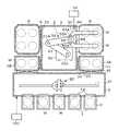
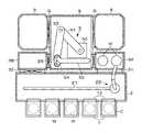
本実施の形態に係る基板処理装置の一例である真空処理装置について説明する。図1、図2に示すように、この真空処理装置は、その内部雰囲気が乾燥ガス、例えば乾燥した空気あるいは窒素ガスにより常圧雰囲気(空気の場合には大気雰囲気ということもできる)とされる矩形の常圧搬送室2を備えている。常圧搬送室2には、ウエハWの搬送容器であるキャリアCを載置するための搬入出ポート1が左右方向に5個並べて設置されている。搬入出ポート1側を手前側、常圧搬送室2側を奥側とすると、常圧搬送室2の正面壁には、前記キャリアCの蓋と一緒に開閉されるドア12が取り付けられている。常圧搬送室2内には、ウエハWを搬送するための関節アームで構成された常圧搬送機構である常圧搬送アーム20が設けられている。常圧搬送アーム20は、図示しない移動機構を備え、移動機構により常圧搬送室2の長さ方向に向かって伸びるガイドレール21に沿って移動できるように構成されている。常圧搬送室2、常圧搬送アーム20、搬入出ポート1は、ローダーモジュールに相当する。 A vacuum processing apparatus, which is an example of the substrate processing apparatus according to this embodiment, will be described. As shown in FIGS. 1 and 2, the internal atmosphere of this vacuum processing apparatus is a normal pressure atmosphere (in the case of air, it can also be called an atmospheric atmosphere) with a dry gas such as dry air or nitrogen gas. A rectangular normal
図1に示すように常圧搬送室2を手前側から見て奥側の壁の右寄り及び左寄りの位置には、夫々ロードロックモジュールであるロードロック室3A、3Bが設けられている。ロードロック室3A、3Bは、搬入出ポート1から奥側を見て、真空搬送室9の横方向の中心を通る中心軸に対して互いに鏡像対称に構成されている。 As shown in FIG. 1, load-
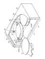
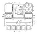
ロードロック室3A、3Bは鏡像対称であることから、ここでは右側のロードロック室3Aについて説明する。図1、図2に示すようにロードロック室3Aは、形状が真空処理装置の左右方向に伸びる矩形の真空容器30を備えている。真空容器30における常圧搬送室2側の側面には、搬送口31が形成され、搬送口31には、ゲートバルブ32が設けられている。またロードロック室3Aの搬送口31からロードロック室3A内を見て左側の面には、ウエハWの搬送口33が形成され、搬送口33は、搬送口33を開閉するゲートバルブ34を介して、共通の真空搬送室9が接続されている。 Since the load-
図2に示すようにロードロック室3Aの内部には、搬送口33側から見て、手前側と奥側とにこの順で並ぶように、ウエハWを水平な姿勢で載置するウエハ載置棚300A、300Bが設けられている。ウエハ載置棚300A、300Bは、3本の支柱35と、各支柱35から水平に伸び出す爪部36を備えており、この爪部36にウエハWの周縁部を支持させることにより、ウエハWを水平な姿勢で保持することができる。 As shown in FIG. 2, inside the load-
爪部36は、各支柱35の異なる2つの高さ位置に設けられており、各ウエハ載置棚300A、300Bは、各々ウエハWを2段で保持することができる。この時ウエハ載置棚300Aの上段側のウエハWの保持する高さ位置と、ウエハ載置棚300Bの上段側のウエハWの保持する高さ位置とは同じであり、ウエハ載置棚300Aの下段側のウエハWの保持する高さ位置と、ウエハ載置棚300Bの下段側のウエハWの保持する高さ位置とは同じである。
なお各支柱35は、各々搬送口31側及び搬送口33側からロードロック室3A内にウエハWを搬入しようとしたときに、ウエハWと干渉しない位置に設けられている。また爪部36は、常圧搬送アーム20及び後述の真空搬送アーム5を昇降させたときに各アームと干渉しないように位置に設けられている。The
Each
またロードロック室3Aは、ロードロック室3A内を排気して真空雰囲気とするための図示しない排気口が形成されると共に、ロードロック室3A内に不活性ガス例えば窒素(N2)ガスを供給して大気雰囲気(常圧雰囲気)にするための図示しないガス供給口が設けられている。これによりロードロック室3A内を真空雰囲気と常圧雰囲気との間で切り替えることができる。The load-
図1に示すように真空搬送室9は手前側から奥側に向かって伸びる概略矩形に構成され、底面部にその内部を真空雰囲気とするための排気口9Aが形成され、排気口9Aは、真空排気部10に接続されている。また搬入出ポート1から見て真空搬送室9の左右の側面には、処理モジュール6が各々接続されている。図1に示すように真空搬送室9における中心部から外れた位置、ここでは、搬入出ポート1から見て真空搬送室9の手前寄りの位置における中心部の右側の側壁の手前に基板搬送機構である真空搬送アーム5が設けられている。 As shown in FIG. 1, the
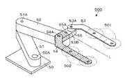
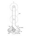
図3、図4に示すように真空搬送アーム5は、基台50に接続された下段腕部51と、下段腕部51の先端に連結された上段腕部52と、を備えている。基台50及び下段腕部51と、下段腕部51及び上段腕部52と、は、夫々鉛直に伸びる回動軸50A、51Aを介して鉛直軸周りに回動自在に連結された多関節アームとして構成されている。また基台50に図示しない昇降機構が設けられており、下段腕部51及び上段腕部52が昇降自在に構成されている。基台50、下段腕部51、上段腕部52は、移動体に相当する。 As shown in FIGS. 3 and 4 , the
上段腕部52の先端には、ウエハWを保持するウエハ保持部500が設けられている。ウエハ保持部500は、第1のアーム53、第2のアーム54及び第1のアーム53及び第2のアーム54を支持する支持体である回動体55を備えている。ウエハ保持部500は、回動体55の中心部を通り鉛直方向に伸びる第3の回動軸55Aを介して上段腕部52の先端に回動自在に接続されている。 A
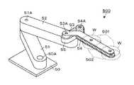
図3、図4中の回動体55から見て、第1のアーム53の先端側が伸びる方向を前方とすると、詳しくは後述するが、ウエハ保持部500は図3に示すように第1のアーム53と、第2のアーム54と、が左右に距離をあけて伸びる形態と、図4に示すように第1のアーム53と、第2のアーム54と、が上下に揃った位置を伸びる形態とを切り替えることができる。ウエハ保持部500の構成を説明するにあたっては、図3の状態をもとに説明する。 Assuming that the direction in which the distal end side of the
図3に示すように回動体55は、平面で見て左右方向に伸びる部材である。回動体55の上面における左側の端部寄りの位置には、鉛直方向に伸びる第1の回動軸53Aを介して第1のアーム53が接続されている。また回動体55の上面における右側の端部寄りの位置には、鉛直方向に伸びる第2の回動軸54Aを介して第2のアーム54が接続されている。なおこの例では、第1の回動軸53Aと、第2の回動軸54Aと、は第3の回動軸55Aに対して対称な位置に設けられている。 As shown in FIG. 3, the rotating
第1のアーム53の基端の下面側には、第1のアーム53先端側の下面の高さ位置を第2のアーム54に保持されたウエハWの上面の高さ位置よりも高くするための台座部53Bが設けられている。なお第1のアーム53の上面の高さ位置と第2のアーム54の上面の高さ位置との距離は、ロードロック室3A、3B内に設けられた各ウエハ載置棚300A、300Bにおける上段側のウエハWを保持する高さ位置と下段側のウエハWを保持する高さ位置との距離と揃うように設定されている。 On the lower surface side of the base end of the
第1のアーム53は、基端側が第1の回動軸53Aから左前方に向かって伸び、先端側が前方に向かって伸びるように屈曲している。なお第1のアーム53を前方に向かって見たときに、第1のアーム53の先端側は、第1の回動軸53Aから左側に、第1の回動軸53Aと回動体55の中心部との間の離間距離と同じ距離だけ離れるように構成されている。 The
第2のアーム54の下面には、台座部が設けられておらず、第2のアーム54は、基端側が第2の回動軸54Aから右前方に向かって伸び、先端側が前方に向かって屈曲している。また第2のアーム54を前方に向かって見たときに、第2のアーム54の先端側は、第2の回動軸54Aから右側に、第1の回動軸53Aと回動体55の中心部との間の離間距離と同じ距離だけ離れるように構成されている。なお第1のアーム53と、第2のアーム54とは平面で見たときに第3の回動軸55Aを通り前後方向に伸びる軸線Lに対して鏡面対称となっている。 A pedestal is not provided on the lower surface of the
第1のアーム53の先端側の前後方向に伸びる部位には、回動体55の外側において長さ方向に沿って2枚のウエハWを支持する第1の基板支持領域501が形成され、第2のアーム54の先端側の前後方向に伸びる部位には、回動体55の外側において長さ方向に沿って2枚のウエハWを支持する第2の基板支持領域502が形成されている。 A first
図3の状態にて、第1の基板支持領域501における2枚のウエハWの支持領域と、第2の基板支持領域502における2枚のウエハWの支持領域とは、互いに軸線Lに対して鏡面対称に配置されている。
以上説明した図3に示す形態は、後述の処理モジュール6に対してウエハWを受け渡すときに第1のアーム53、第2のアーム54がとる形態である。そして図4に示す形態は、ロードロック室3A、3Bに対してウエハを受け渡すときに第1のアーム53、第2のアーム54がとる形態である。In the state of FIG. 3, the support area for the two wafers W in the first
The form described above and shown in FIG. 3 is the form taken by the
図5A~5Dは、図3に示す形態と、図4に示す形態と間の第1のアーム53、及び第2のアーム54の形態の変化を示す。なお図3では、第1の基板支持領域501と第2の基板支持領域502とが左右に離間するように配置されることから以下明細書中では、「ウエハWを平置きで支持する形態」と呼び、図4では、第1の基板支持領域501と第2の基板支持領域502とが上下に重なるように配置されることから以下明細書中では、「ウエハWを段積みで支持する形態」と呼ぶものとする。 5A-5D show variations in the configuration of
図5Aは、図3に示す形態であり、この形態から回動体55を上方から見て反時計回りに回動する。この時第1のアーム53、及び第2のアーム54は、回動体55の回動に合わせて、上方から見て回動体55に対して時計回りに回転する。このように回動体55の回動に合わせて第1のアーム53、及び第2のアーム54を回動させることにより、第1のアーム53、及び第2のアーム54は、先端の向きが保たれ、互いに平行な状態を維持する。 FIG. 5A shows the form shown in FIG. 3, in which the
そして第1のアーム53、第2のアーム54及び回動体55を回動させることにより図5Aの形態から図5Bに示すように第1のアーム53、及び第2のアーム54の先端の距離が徐々に近くなる。さらに第1のアーム53、第2のアーム54及び回動体55を回動させることで、第2のアーム54が第1のアーム53の下方にもぐる。そして図5Aの形態から回動体55を180°回動させると、図5Dに示すように第1のアーム53及び第2のアーム54に夫々形成された第1の基板載置領域501及び第2の基板載置領域502が平面視、軸線L上に揃い互いに重なる。これによりウエハWを平置きで支持する形態から、ウエハWを段積みで支持する形態に切り替えることができる。 By rotating the
また図5Aから図5Dの逆の動作、即ち図5D、5C、5B、5Aの順で動作させることにより、ウエハWを段積みで支持する形態からウエハWを平置きで支持する形態に戻る。 5A to 5D, that is, by performing the operations in the order of FIGS. 5D, 5C, 5B, and 5A, the wafer W is returned from being supported in a stacked manner to being supported in a horizontal position.
既述のようにウエハ保持部500は、回動体55と、第1のアーム53及び第2のアーム54を互いに独立して回動させることができる。そのような駆動機構の一例を図6、7に示す。図6、図7は、夫々ウエハ保持部500の側断面図及び縦断正面図を示す。図6、図7に示すように上段腕部52の内部には基台50側の図示しないモータにより駆動されるベルト91を備え、ベルト91は、第3の回動軸55Aを鉛直軸周りに回動させるように設けられ、第3の回動軸55Aを回動させることにより回動体55が上段腕部52に対して独立して回動する。 As described above, the
また上段腕部52の内部の先端側には、プーリ93が設けられ、プーリ93には、第3の回動軸55Aの内部を上方に向かって伸びるアーム用回動軸90の下端が接続されている。なお第3の回動軸55Aと、アーム用回動軸90と、の間には、わずかな隙間が設けられており、第3の回動軸55Aと、アーム用回動軸90と、互いに干渉しないように回動することができる。またアーム用回動軸90の上端には、回動体55内部に設けられたギア94に接続されており、ギア94の回転により、第1のギアボックス95内のギアが回動し、第1の回動軸53Aを介して、第1のアーム53が回動する。またギア94の回転により、第2のギアボックス96内のギアが回動し、第2の回動軸54Aを介して、第2のアーム54が回動する。このような構成により第1のアーム53及び第2のアーム54と、回動体55とを互いに独立して回動させることができる。 A
そしてベルト91、92をいずれも回転させたとき、例えばベルト91、92を同じ方向に同時に回転させたときには、第1のアーム53、及び第2のアーム54が回動体55の回動に合わせて、回動体55の回動方向と同じ方向に回動する。このように第1のアーム53、及び第2のアーム54を回動体55の回動に合わせて回動させることで、回動体55に対する第1のアーム53、及び第2のアーム54の相対的な位置が変わらない。このように第1のアーム53及び第2のアーム54を回動体55に対して相対的に回動させずに、回動体55を回動させることで、第1のアーム53と第2のアーム54と、の間の距離を一定にしたまま回動体55を回動させる第1の回動動作を行うことができる。 When both the
また2本のベルト91、92のうちベルト91のみを回転させることで、第1のアーム53、及び第2のアーム54の先端側が伸びる方向を変えずに回動体55だけ回動させることができる。この時第1のアーム53、及び第2のアーム54は、回動体55に対して相対的に回動することで、図5A~Dに示すように第1のアーム53と第2のアーム54と、の間の距離を変更することができ、例えば図3に示すウエハWを平置きで支持する形態と、図4に示すウエハWを段積みで支持する形態とを切り替える第2の回動動作を実行することができる。 Further, by rotating only the
続いて処理モジュール6について、図8の縦断側面図を参照しながら説明する。2つの処理モジュール6は、ウエハWにプラズマALD(Atomic Layer Deposition)により成膜する成膜モジュールであり、2つとも同様に構成され、処理モジュール6間で互いに並行してウエハWの処理を行うことができる。処理モジュール6は、平面視、矩形の真空容器(処理容器)61を備えており(図1参照)、真空容器61の側壁にはゲートバルブGによって開閉されるウエハWの搬送口62が開口している。図8中の符号63は真空容器61の底面に開口した排気口であり、排気管64を介して真空ポンプ65に接続されている。図8中の符号66は排気管64に介設された圧力調整部であり、真空容器61内が所望の圧力の真空雰囲気となるように真空ポンプ65による排気口63からの排気量を調整する。 Next, the
真空容器61内には、搬送口62から見て、手前から奥に向けてウエハWを載置する載置台67A、67Bが列をなしてこの順に設けられ、この載置台67A、67Bの列は搬送口62から見て左右に並べられて設けられることで、平面で見てウエハWは真空容器61内に2×2の行列状に、合計4枚載置される。載置台67A、67Bは互いに同様に構成されており、円形且つ水平に形成されている。図9に示すように搬送口62から見て左側の載置台67Aと、載置台67Bと、は、夫々ウエハWを平置きで支持する形態としたウエハ保持部500における第1のアーム53の基端側の第1の基板支持領域501と、先端側の第1の基板支持領域501と、に対応する位置に設けられている。また搬送口62から見て右側の載置台67Aと、載置台67Bと、は、夫々ウエハWを平置きで支持する形態としたウエハ保持部500における第2のアーム54の基端側の第2の基板支持領域502と、先端側の第2の基板支持領域502と、に対応する位置に設けられている。図8中の符号70は載置台67A、67Bに各々埋設されたヒーターであり、載置台67A、67Bに載置された各ウエハWを300℃~450℃に加熱する。 Placement tables 67A and 67B for placing wafers W thereon are arranged in rows in this order from the front to the back when viewed from the
図8中の符号68は真空容器61の底面の中央部を貫通する支柱であり、当該支柱68の上端からは4つの支持アーム69が水平に放射状に伸びて、載置台67A、67Bを下方側から支持している。支柱68の下端側は、真空容器61の下方外側で昇降機構71に接続されており、当該昇降機構71により支柱68及び支持アーム69を介して載置台67A、67Bが、図8中に実線で示す位置と鎖線で示す位置との間で昇降する。実線で示す位置は、ウエハWを処理するための処理位置であり、鎖線で示す位置は、載置台67A、67Bと上記の真空搬送アーム5との間でウエハWを受け渡すための受け渡し位置である。なお、図8中の72は、真空容器61内を気密に保つためのシール部材である。
図8、図9に示すように各載置台67A、67Bには、第1のアーム53及び第2のアーム54を避けるように3つの貫通孔73が形成されており(図8では2つのみ表示している)、各貫通孔73には真空搬送アーム5との間でウエハWを受け渡すために昇降する昇降ピン75が設けられている。図8中の符号74は、昇降ピン75を昇降させる昇降機構74であり、真空容器61の下方の外側に設けられている。なお図8中の76は、真空容器61内の気密性を確保するためのベローズである。
As shown in FIGS. 8 and 9, three through-
真空容器61の天井において載置台67A及び67Bの上方には、絶縁部材77Aを介してガスシャワーヘッド77が各々設けられている。ガスシャワーヘッド77の下面は載置台67A、67Bに対向し、当該下面にはガス吐出孔78が多数、分散して配設されている。またガスシャワーヘッド7には整合器701を介して高周波電源702が接続される。また載置台67A、67B内には、図示しない下部電極が埋設されており、下部電極は、接地電位に接続されている。図8中の符号79はガス供給部であり、ガスシャワーヘッド77に四塩化チタン(TiCl4)、水素(H2)ガス、アルゴン(Ar)ガス、窒素(N2)ガスを夫々独立して供給し、これらのガスがガス吐出口78から各々吐出される。Gas shower heads 77 are provided on the ceiling of the
処理モジュール6によるウエハWの成膜処理について説明すると、受け渡し位置に位置する2つの載置台67A、2つの載置台67BにウエハWが載置された後、ヒーター70によりウエハWが加熱されると共に載置台67A、67Bが上昇して処理位置に移動する。次いで、ガスシャワーヘッド77から成膜用のガスとしてTiCl4ガスを供給し、ウ
エハWの表面に吸着させる。さらに反応ガスとしてArガス及びH2ガスを供給する。さらに高周波電源702からガスシャワーヘッド77と載置台67A、67B内の下部電極との間に高周波電力を印加することにより供給された反応ガスを容量結合によりプラズマ化する。これによりTiCl4ガスとH2ガスとが活性化されて反応し、ウエハWの表面にTi(チタン)の層が成膜される。
このようにTiCl4ガスの吸着、Arガス及びH2ガスの供給と共に反応ガスのプラズマ化を順番に複数回繰り返す。これにより上記のTi層の形成が繰り返し行われて、所望の膜厚を有するTi膜が形成される。
The film forming process of the wafer W by the
In this way, the adsorption of TiCl4 gas, the supply of Ar gas and H2 gas, and the conversion of reaction gas into plasma are sequentially repeated several times. As a result, the formation of the Ti layer is repeated to form a Ti film having a desired film thickness.
真空処理装置は、図1に示すように真空処理装置内におけるウエハWの搬送、真空搬送アーム5におけるウエハ保持部500の切り替え機構の駆動、処理モジュール6における成膜処理のプロセス、ロードロック室3A、3Bにおける雰囲気の切り替えを制御する制御部100を備えている。制御部100は例えば図示しないCPUと記憶部とを備えたコンピュータからなり、この記憶部には処理モジュール6における成膜処理のレシピや、当該真空処理装置において、常圧搬送アーム20及び真空搬送アーム5によるウエハWの搬送行うためのステップ(命令)群が組まれたプログラムが記録されている。このプログラムは、例えばハードディスク、コンパクトディスク、マグネットオプティカルディスク、メモリカードなどの記憶媒体に格納され、そこからコンピュータにインストールされる。 The vacuum processing apparatus, as shown in FIG. 1, carries out the transfer of the wafer W within the vacuum processing apparatus, the drive of the switching mechanism of the
続いて真空処理装置の作用について説明する。図10に示すようにウエハWを収容したキャリアCが搬入出ポート1上に載置されると、当該キャリアC内のウエハWが、常圧搬送アーム20によって取り出され、ロードロック室3A、3Bのウエハ載置棚300に受け渡される。そしてロードロック室3A、3Bの各ウエハ載置棚300にウエハWを載置した後、常圧搬送アーム20を常圧搬送室2に退避させ、ゲートバルブ32を閉じ、ロードロック室3A、3B内の雰囲気を真空雰囲気に切り替える。 Next, the action of the vacuum processing apparatus will be described. As shown in FIG. 10, when the carrier C accommodating the wafers W is placed on the loading/unloading port 1, the wafers W in the carrier C are taken out by the normal
続いて、図11に示すように例えばロードロック室3Aと真空搬送室9との間のゲートバルブ34を開き、真空搬送アーム5のウエハ保持部500をウエハWを段積みで支持する形態に切り替えてロードロック室3Aに進入させる。この時図12に示すように第2のアーム54がロードロック室3Aにおける下段側の2枚のウエハWの下方に進入し、第1のアーム53が上段側の2枚のウエハWの下方に進入する。そして図13に示すように真空搬送アーム5を上昇させると、第1及び第2のアーム53、54は、ロードロック室3A内の4枚のウエハWを一括して掬い上げる。 Subsequently, as shown in FIG. 11, for example, the
次いで図14に示すように真空搬送アーム5をロードロック室3Aから真空搬送室9に退避させ、ゲートバルブ34を閉じる。さらに真空搬送アーム5の回動体55を回動させてウエハWを平置きで支持する形態に切り替える(第2の回動動作を実行する)。
そして図15に示すように例えば真空処理装置の手前側から見て、真空搬送室9の右側の処理モジュール6のゲートバルブGを開き、ウエハWを平置きで支持する形態でウエハ保持部500を処理モジュール6内に進入させる。
この時ウエハ保持部500を処理モジュール6に進入させたときに真空搬送アーム5に支持されている4枚のウエハWは、夫々処理モジュール6の4台の載置台67A、67Bの上方に位置する。そして、各載置台67A、67Bに設けられた昇降ピン75を上昇させて、昇降ピン75により真空搬送アーム5に支持されているウエハWを夫々突き上げて受け取る。さらに真空搬送アーム5を真空搬送室9に退避させ、昇降ピンを下降させ、各載置台67A、67Bにウエハを載置する。このように4枚のウエハWは、夫々対応する載置台67A、67Bに一括して受け渡される。Next, as shown in FIG. 14, the
Then, as shown in FIG. 15, for example, when viewed from the front side of the vacuum processing apparatus, the gate valve G of the
At this time, when the
同様に真空処理装置の手前側から見て真空搬送室9の左側に設けられた処理モジュール6にロードロック室3B内に搬送されたウエハWが真空搬送アーム5によって一括して受け渡される。その後各処理モジュール6にて、ウエハWに既述の成膜処理が行われる。 Similarly, the wafers W transferred into the
各処理モジュール6で成膜処理を終えると、図16に示すように各載置台67A、67BのウエハWを昇降ピン75で突き上げた状態とし、例えば手前側から見て右側の処理モジュール6におけるゲートバルブGを開く。そしてウエハ保持部500をウエハWを平置きで支持する形態で処理モジュール6に進入させる。この時第1のアーム53及び第2のアーム54は、夫々対応するウエハWの下方に第1の基板支持領域501、第2の基板支持領域502を揃える位置に進入しており、昇降ピン75を下降させることで4枚のウエハWが一括して第1のアーム53、第2のアーム54に受け渡される。なお図16~18では、処理済みのウエハWにハッチングを付して示している。 After finishing the film formation process in each
次いで図17に示すようにウエハ保持部500を真空搬送室9に退避させ、さらにウエハ保持部500をウエハWを段積みで支持する形態に切り替える。その後、図18に示すようにロードロック室3Aの真空搬送室9側のゲートバルブ34を開き、真空搬送アーム5をウエハWを段積みで支持する形態でロードロック室3Aに進入させる。この時図19示すように第1のアーム53及び第2のアーム54の先端側に支持されているウエハWが夫々ウエハ載置棚300Bの上段側及び下段側のウエハWを保持する爪部36の上方に位置する。また第1のアーム53及び第2のアーム54の基端側に支持されているウエハWが夫々ウエハ載置棚300Aの上段側及び下段側のウエハWを保持する爪部36の上方に位置する。さらに図20に示すように真空搬送アーム5を下降させることにより、第1のアーム53及び第2のアームに保持されたウエハWがウエハ載置棚300A、300Bに受け渡される。 Next, as shown in FIG. 17, the
その後真空搬送アーム5を真空搬送室9に退避させ、ロードロック室3Aにおいては、ゲートバルブ34を閉じた後、常圧雰囲気に切り替える。さらに常圧搬送室2側のゲートバルブ32を開き、常圧搬送アーム20により、ウエハ載置棚300A、300Bに支持された4枚の処理済みウエハWをキャリアCに戻す。 After that, the
さらに真空搬送アーム5は、真空搬送装置の手前側から見て真空搬送室9の左側の処理モジュール6から処理済みのウエハWを取り出し、同様にロードロック室3Bに搬送する。その後常圧搬送アーム20により、ロードロック室3Bから処理済みのウエハWを取り出し、キャリアCに搬送する。 Further, the
ところで真空処理装置においては、装置のスループットを向上させるために処理モジュールを基板を各々保持する載置台を水平に複数、例えば実施の形態に示したように載置台67A、67Bを2×2の行列状に4台設けた構成とし、各々の載置台67A、67BでウエハWの処理をする装置が知られている。このような装置においては装置のスループットをさらに向上させるため、処理モジュールに基板を搬送する真空搬送機構を、従来は2×2の行列状に配置された4枚の基板を平置きで支持し、一括して受け渡しを行う装置としていた。 By the way, in the vacuum processing apparatus, in order to improve the throughput of the apparatus, a plurality of mounting tables for holding the substrates of the processing modules are arranged horizontally, for example, the mounting tables 67A and 67B are arranged in a 2×2 matrix as shown in the embodiment. An apparatus is known in which four wafers W are processed on respective mounting tables 67A and 67B. In such an apparatus, in order to further improve the throughput of the apparatus, the vacuum transfer mechanism for transferring the substrates to the processing module conventionally supports four substrates arranged in a 2×2 matrix in a horizontal position. It was used as a device for batch delivery.
しかしながら従来型の4枚の基板を平置きで支持する真空搬送機構の場合には、処理モジュールに搬入する基板を真空搬送機構に受け渡すためのモジュール、例えば真空搬送機構が設けられる真空搬送室9に接続されるロードロックモジュール側においても同様に4枚の基板を2×2の行列状に平置きで配置し、基板を真空搬送機構に一括して受け渡すようにする必要がある。そのためロードロックモジュール側に水平に4枚の基板を載置する領域を確保する必要があり装置の設置面積が大型化してしまう問題がある。 However, in the case of a conventional vacuum transfer mechanism that supports four substrates in a flat position, a
またロードロックモジュール側において、水平に並ぶ基板の枚数を少なくすることで、例えば基板を2枚×2段の段積みとすることで装置の設置面積の大型化を避けることができる。しかしながらこの場合には、2×2の行列状に載置台が設けられた処理モジュールに基板を搬送するにあたって真空搬送装置を水平に2枚の基板を支持する構成として基板を2枚ごと2回アクセスさせる必要がある。あるいは真空搬送機構を2枚×2段の段積み保持する機構を採用し、基板を2段の段積みで受け取り、処理モジュール側に新たに段積みで支持された基板を平積みで支持するように展開する移載機構を設け、基板を平積みで支持するように展開する工程が必要になるなどスループットが低下する問題がある。
また処理モジュール内に移載機構を設けることでパーティクル発生の要因ともなるおそれがある。In addition, by reducing the number of horizontally arranged substrates on the load lock module side, for example, by stacking two substrates in two stages, it is possible to avoid an increase in the installation area of the apparatus. However, in this case, when the substrates are transferred to the processing module having the mounting tables arranged in a 2×2 matrix, the vacuum transfer apparatus is configured to horizontally support the two substrates, and every two substrates are accessed twice. need to let Alternatively, a vacuum transport mechanism may be adopted to hold two stacked substrates in two stages, receive the substrates in two stacked stages, and horizontally support the newly stacked substrates on the processing module side. There is a problem that the throughput is lowered because a transfer mechanism that expands the substrate is provided, and a step of expanding the substrate so as to support the substrate in a flat stack is required.
Also, providing a transfer mechanism in the processing module may cause particle generation.
上述の実施の形態によれば、真空搬送アーム5において回動体55に鉛直軸方向に伸びる第1の回動軸53A及び第2の回動軸54Aを互いに離間するように設けている。さらに第1のアーム53を第1の回動軸53Aから左側に向かって伸び、先端側が前方に屈曲するように設け、第2のアーム54を第2の回動軸54Aから右側に伸び、先端側が前方に屈曲するように、第1のアーム53と異なる高さに設けている。 According to the above embodiment, in the
そして第1のアーム53の先端側と、第2のアーム54の先端側とに夫々、互いに異なるウエハWを第1のアーム53、第2のアーム54の長さ方向に2枚保持する第1の基板支持領域501と第2の基板支持領域502とを設けている。また回動体55に第3の回動軸55Aを設け、第1の基板支持領域501と第2の基板支持領域502との左右の距離を変更するように回動体55を回動させる第1の回動動作と、第1の基板支持領域501と第2の基板支持領域502との互いの距離を変化させずに回動体55を回動させる第2の回動動作と、を切り替えることができるように構成している。 Two different wafers W are held in the length direction of the
そのためウエハWを左右に離間し水平に2×2の行列状に並べて支持する平置きの状態と、ウエハWを上下に2枚×2段に配置して支持できる段積みの状態で切り替えることができる。このような真空搬送アーム5を真空処理装置に適用することで、処理モジュール6及びロードロック室3A、3Bのレイアウトを広く選択することができる。 Therefore, it is possible to switch between a flat state in which the wafers W are horizontally spaced apart and horizontally arranged in a 2×2 matrix and supported, and a stacked state in which the wafers W are vertically arranged in 2×2 stages and supported. can. By applying such a
従って処理モジュール6に2×2の行列状に並ぶ複数の載置台67A、67Bを設け、ロードロック室3A、3BをウエハWを2枚×2段の段積みで保持する構成とした場合においても、真空搬送アーム5により、複数の載置台67A、67B及びウエハWを段積みで保持するロードロック室3A、3Bのいずれに対してもウエハWを一括で受け渡すことができる。そのため装置の大型化を抑制しながら、スループットを改善することができる。 Therefore, even if the
また真空搬送アーム5は、ウエハWを支持するアームを3本備えていてもよい。例えば図21、図22に示すように例えば第3の回動軸55Aと重なるように第4の回動軸56Aを設け、第4の回動軸56Aから先端側が前方に伸び、第1のアーム53と、第2のアーム54と、の間の高さ位置に位置する第3のアーム56を設ける。そして第3のアーム56の先端側に第1の基板支持領域501及び第2の基板支持領域502の各々で保持するウエハWと異なるウエハWを保持する第3の基板支持領域503を設けている。さらに第3のアーム56も回動体55の回動角度によらず常に前方に向かって伸びる姿勢を維持する。従って第1のアーム53の先端側、第2のアーム54の先端側及び第3のアーム56は、常に平行となっている。 Also, the
このような構成の真空搬送アーム5において、図23Aに示すように回動体55を第1の回動軸53Aが左側、第2の回動軸54Aを右側に移動するように回動させることで第1の基板支持領域501、第2の基板支持領域502及び第3の基板支持領域503が左右方向に離れるように配置され、6枚のウエハWを平置きで支持する形態となる。さらに図23Aの状態から回動体55を上方から見て反時計回りに回動すると、図23B、図23Cに示すように第1のアーム53の先端側、第2のアーム54の先端側及び第3のアーム56が互いに平行を維持したまま、互いの距離を徐々に短くする。そして図23Aの状態から回動体55を上方から見て反時計回りに180°回動させると図23Dに示すように第1の基板支持領域501、第2の基板支持領域502及び第3の基板支持領域503の水平方向の位置が互いに揃い、上下方向にウエハを3段の段積みで支持する形態とすることができる。 In the
このような真空搬送アーム5を用いることで処理モジュール6に設ける載置台67A、67Bを搬送口側から見て3列×2行の行列状に配置し、ロードロック室3A、3Bを3段の構成とすることができる。 By using such a
さらに図24A、24Bに真空搬送アーム5の更に他の例を示す。この真空搬送アーム5のウエハ保持部500は、回動体55に互いに離間するように設けられた鉛直方向に伸びる第1の回動軸53Aと、第2の回動軸54Aと、を備えている。第1のアーム53は、第1の回動軸53Aから左側前方に伸びだし、先端側が屈曲して前方に伸びている。また第1のアーム53の第1の回動軸53Aから前方に向かって屈曲する部位までの距離は、第1の回動軸53Aと、第2の回動軸54Aと、の離間距離と同じ距離に設定されている。さらに第2のアーム54は第2の回動軸54Aから前方に向かって伸びるように構成されている。そして第1のアーム53及び第2のアーム54には夫々ウエハを保持する第1の基板支持領域501及び第2の基板支持領域502が設けられている。 Further, still another example of the
このような真空搬送アーム5において、図24Aに示すように第1の回動軸53Aを通り前後方向に伸びる軸線L´と第1のアームの基端側の部位が伸びる方向のなす角度θ1と、軸線L´と、回動体55の伸びる方向がなす角度θ2とが同じ角度となるように回動体55を回動させることにより、第1の基板支持領域501と、第2の基板支持領域502と、が左右に離間しウエハWを平置きで支持する形態とすることができる。 In such a
さらに回動体55を図24Aの状態から反時計回り方向に回動させ、図24Bに示すように回動体55を第1のアーム53の下方に揃えることで、第2のアーム54も第1のアーム53の下方に揃う位置に移動する。この時第1の基板支持領域501と、第2の基板支持領域502と、の位置が揃い、ウエハWを段積みで支持する形態とすることができる。このような構成とした場合にも回動体55を回動させることで、真空搬送アーム5のウエハ保持部500をウエハWを平置きで保持する状態と、ウエハを段積みで保持する状態とで切り替えることができるため同様の効果を得ることができる。 Further, by rotating the
さらに支持体に第2の回動動作において、平行される第1のアーム53と第2のアーム54と間の第2の距離は、第1の基板支持領域と第2の基板支持領域とが上下に重なることは必須ではなく、第2の回動動作を行った時に第1の基板支持領域と第2の基板支持領域との左右の距離が、第1の距離で平行に並ぶ状態と、第1の距離よりも狭い第2の距離で平行に並ぶ状態との間で切り替えられれば良い。
さらには第1の基板支持領域、第2の基板支持領域及び第3の基板支持領域にて支持される基板の枚数は夫々2枚とは限らず、1枚あるいは、3枚以上であってもよい。また基板搬送機構は、ロードロック室と、処理モジュールと、の間で基板を受け渡すことは必須ではなく。例えば真空搬送室9に複数の基板を仮置きするための仮置き部を接続し、仮置き部と、処理モジュールとの間で基板を受け渡す基板搬送機構に適用してもよい。Further, in a second pivoting motion to the support, a second distance between the parallel
Furthermore, the number of substrates supported by the first substrate support area, the second substrate support area, and the third substrate support area is not limited to two, and may be one or three or more. good. Also, it is not essential that the substrate transfer mechanism transfer substrates between the load lock chamber and the processing modules. For example, the
以上に検討したように、今回開示された実施形態はすべての点で例示であって制限的なものではないと考えられるべきである。上記の実施形態は、添付の請求の範囲及びその主旨を逸脱することなく、様々な形態で省略、置換、変更されてもよい。 As discussed above, the embodiments disclosed this time should be considered illustrative and not restrictive in all respects. The embodiments described above may be omitted, substituted, or modified in various ways without departing from the scope and spirit of the appended claims.
2 常圧搬送室
3A,3B ロードロック室
6 処理モジュール
5 真空搬送アーム
53 第1のアーム
53A 第1の回動軸
54 第2のアーム
54A 第2の回動軸
55 回動体
55A 第3の回動軸
56 第3のアーム
56A 第4の回動軸
500 ウエハ保持部
501 第1の基板支持領域
502 第2の基板支持領域
503 第3の基板支持領域
W ウエハ2 normal
Claims (8)
Translated fromJapanese前記移動体に支持される支持体と、
前記支持体に互いに離れて設けられる各々縦方向の第1の回動軸及び第2の回動軸と、
前記第1の回動軸から前方に向けて伸び、その先端側が前記支持体の外側で基板を支持する第1の基板支持領域をなす第1のアームと、
前記第2の回動軸から前方に向けて伸び、その先端側が前記支持体の外側で前記第1のアームに支持される基板とは別の基板を支持する第2の基板支持領域をなすように、第1のアームとは異なる高さに設けられる第2のアームと、
前記移動体に対して前記支持体を回動させるための縦方向の第3の回動軸と、
前記第1の基板支持領域と第2の基板支持領域との左右の距離が保たれるように前記支持体を回動させる第1の回動動作と、前記左右の距離が第1の距離と当該第1の距離よりも狭い第2の距離との間で変更されるように前記第1の回動軸及び第2の回動軸のうちの少なくとも一方の回動と共に前記支持体を回動させる第2の回動動作と、を切り替えて行う切り替え機構と、を備え、
前記第3の回動軸は、左右方向において前記第1の回動軸と、前記第2の回動軸との間に設けられ、
前記切り替え機構は前記第2の回動動作において、前記第1の回動軸及び第2の回動軸を回動させ、
基端側が前記第1の回動軸から左右の一方に向かって伸び、先端側が前方へ向かって伸びるように前記第1のアームは屈曲し、
基端側が前記第2の回動軸から左右の他方に向かって伸び、先端側が前方へ向かって伸びるように前記第2のアームは屈曲する基板搬送機構。a moving body that moves laterally;
a support supported by the moving body;
a first longitudinal pivot axis and a second longitudinal pivot axis spaced apart from each other on said support;
a first arm extending forward from the first rotation shaft and having a tip side thereof forming a first substrate supporting region for supporting the substrate outside the support;
A second substrate support area extending forward from the second rotation shaft and having a distal end thereof forming a second substrate support area for supporting a substrate different from the substrate supported by the first arm outside the support member a second arm provided at a different height than the first arm;
a longitudinal third pivot axis for pivoting the support relative to the mover;
a first rotation operation for rotating the support body so that the lateral distance between the first substrate supporting area and the second substrate supporting area is maintained; and the lateral distance equal to the first distance. rotating the support together with rotating at least one of the first rotating shaft and the second rotating shaft so as to change between a second distance narrower than the first distance;and a switching mechanism that switches between
the third rotating shaft is provided between the first rotating shaft and the second rotating shaft in the left-right direction;
The switching mechanism rotates the first rotation shaft and the second rotation shaft in the second rotation operation,
the first arm is bent such that the proximal side extends toward one of the left and right sides from the first rotation shaft and the distal side extends forward;
The substrate transport mechanism, wherein the second arm is bent such that the base end side extends toward the other of the left and right sides from the second rotation shaft and the tip end side extends forward.
当該第4の回動軸から前方に伸び出し、その先端側が前記支持体の外側において前記第1のアーム、第2のアームに各々支持される基板とは別の基板を支持する第3の基板支持領域をなす第3のアームと、
前記第1の基板支持領域と第2の基板支持領域との左右の距離が、前記第1の距離であるときと第2の距離であるときとで前記第3のアームの向きが揃うように前記第3のアームが回動する請求項1ないし3のいずれか一つに記載の基板搬送機構。a vertical fourth pivot shaft overlapping the third pivot shaft;
a third substrate extending forward from the fourth pivot shaft and supporting a substrate different from the substrates supported by the first arm and the second arm on the outer side of the support at its tip end side; a third arm forming a support area;
The direction of the third arm is the same when the horizontal distance between the first substrate supporting region and the second substrate supporting region is the first distance and the second distance. 4. The substrate transfer mechanism according to claim1, wherein said third arm rotates.
前記搬送室に接続され、真空雰囲気で前記基板に処理を行う処理モジュールと、
前記搬送室に接続されるロードロックモジュールと
前記ロードロックモジュールと前記処理モジュールとの間で前記基板を搬送するために前記搬送室に設けられる請求項1ないし5のいずれか一つに記載の基板搬送機構と、
前記基板を格納した搬送容器が載置され、当該搬送容器と前記ロードロックモジュールとの間で前記基板を搬送するローダーモジュールと、
を備える基板処理装置。a transfer chamber in a vacuum atmosphere;
a processing module connected to the transfer chamber for processing the substrate in a vacuum atmosphere;
6. The substrate according to any one of claims 1 to5 , wherein a load lock module connected to said transfer chamber and a substrate provided in said transfer chamber for transferring said substrate between said load lock module and said processing module. a transport mechanism;
a loader module on which a transport container containing the substrates is mounted and which transports the substrates between the transport container and the load lock module;
A substrate processing apparatus comprising:
少なくとも前記処理モジュールに前記基板を受け渡すときには前記第1の距離とされる請求項6記載の基板処理装置。Regarding the left and right distances,
7. The substrate processing apparatus according to claim6 , wherein said first distance is set at least when said substrate is transferred to said processing module.
前記移動体に支持される支持体に互いに離れて設けられる縦方向の第1の回動軸及び第2の回動軸を各々回動させる工程と、
前記第1の回動軸から前方に伸び、その先端側が前記支持体の外側で第1の基板支持領域をなす第1のアームに基板を支持する工程と、
前記第2の回動軸から前方に伸び、その先端側が前記支持体の外側で第2の基板支持領域をなすと共に前記第1のアームとは異なる高さに設けられる第2のアームに、前記第1のアームに支持される基板とは別の基板を支持する工程と、
縦方向の第3の回動軸まわりに前記移動体に対して前記支持体を回動させる工程と、
前記第1の基板支持領域と第2の基板支持領域との左右の距離が保たれるように前記支持体を回動させる第1の回動動作を行う工程と、
前記左右の距離が第1の距離と当該第1の距離よりも狭い第2の距離との間で変更されるように前記第1の回動軸及び第2の回動軸のうちの少なくとも一方の回動と共に前記支持体を回動させる第2の回動動作を行う工程と、
切り替え機構により前記第1の回動動作と、前記第2の回動動作とを切り替える工程と、
を備え、
前記第2の回動動作を行う工程は、前記切り替え機構により前記第1の回動軸及び第2の回動軸を回動させる工程を含み、
前記第3の回動軸は、左右方向において前記第1の回動軸と、前記第2の回動軸との間に設けられ、
基端側が前記第1の回動軸から左右の一方に向かって伸び、先端側が前方へ向かって伸びるように前記第1のアームは屈曲し、
基端側が前記第2の回動軸から左右の他方に向かって伸び、先端側が前方へ向かって伸びるように前記第2のアームは屈曲する基板搬送方法。laterally moving the moving body;
a step of respectively rotating a first vertical rotation shaft and a second vertical rotation shaft provided separately from each other on a support supported by the movable body;
a step of supporting the substrate on a first arm extending forward from the first rotation shaft and having a tip end thereof forming a first substrate supporting area outside the support;
A second arm extending forward from the second pivot shaft, having a distal end thereof forming a second substrate supporting region outside the support, and provided at a height different from that of the first arm, supporting a substrate other than the substrate supported by the first arm;
rotating the support relative to the moving body about a third longitudinal rotation axis;
a step of performing a first rotation operation of rotating the support body so as to maintain a lateral distance between the first substrate support area and the second substrate support area;
At least one of the first rotating shaft and the second rotating shaft such that the left and right distance is changed between a first distance and a second distance narrower than the first distance a step ofperforming a second rotation operation of rotating the support together with the rotation of
switching between the first rotating motion and the second rotating motion by a switching mechanism;
with
The step of performing the second rotating operation includes rotating the first rotating shaft and the second rotating shaft by the switching mechanism,
the third rotating shaft is provided between the first rotating shaft and the second rotating shaft in the left-right direction;
the first arm is bent such that the proximal side extends toward one of the left and right sides from the first rotation shaft and the distal side extends forward;
The substrate transfer method, wherein the second arm is bent such that the base end extends toward the other of left and right from the second rotating shaft and the tip end extends forward.
Priority Applications (3)
| Application Number | Priority Date | Filing Date | Title |
|---|---|---|---|
| JP2018163103AJP7183635B2 (en) | 2018-08-31 | 2018-08-31 | SUBSTRATE TRANSFER MECHANISM, SUBSTRATE PROCESSING APPARATUS AND SUBSTRATE TRANSFER METHOD |
| US16/548,652US10872798B2 (en) | 2018-08-31 | 2019-08-22 | Substrate transfer mechanism, substrate processing apparatus, and substrate transfer method |
| KR1020190106633AKR102244352B1 (en) | 2018-08-31 | 2019-08-29 | Substrate transfer mechanism, substrate processing apparatus, and substrate transfer method |
Applications Claiming Priority (1)
| Application Number | Priority Date | Filing Date | Title |
|---|---|---|---|
| JP2018163103AJP7183635B2 (en) | 2018-08-31 | 2018-08-31 | SUBSTRATE TRANSFER MECHANISM, SUBSTRATE PROCESSING APPARATUS AND SUBSTRATE TRANSFER METHOD |
Publications (3)
| Publication Number | Publication Date |
|---|---|
| JP2020035954A JP2020035954A (en) | 2020-03-05 |
| JP2020035954A5 JP2020035954A5 (en) | 2021-07-26 |
| JP7183635B2true JP7183635B2 (en) | 2022-12-06 |
Family
ID=69639975
Family Applications (1)
| Application Number | Title | Priority Date | Filing Date |
|---|---|---|---|
| JP2018163103AActiveJP7183635B2 (en) | 2018-08-31 | 2018-08-31 | SUBSTRATE TRANSFER MECHANISM, SUBSTRATE PROCESSING APPARATUS AND SUBSTRATE TRANSFER METHOD |
Country Status (3)
| Country | Link |
|---|---|
| US (1) | US10872798B2 (en) |
| JP (1) | JP7183635B2 (en) |
| KR (1) | KR102244352B1 (en) |
Families Citing this family (6)
| Publication number | Priority date | Publication date | Assignee | Title |
|---|---|---|---|---|
| JP7225613B2 (en)* | 2018-09-03 | 2023-02-21 | 東京エレクトロン株式会社 | SUBSTRATE TRANSFER MECHANISM, SUBSTRATE PROCESSING APPARATUS AND SUBSTRATE TRANSFER METHOD |
| JP7210960B2 (en)* | 2018-09-21 | 2023-01-24 | 東京エレクトロン株式会社 | Vacuum processing apparatus and substrate transfer method |
| KR102833850B1 (en)* | 2020-03-24 | 2025-07-14 | 주식회사 원익아이피에스 | Transfer Robot and Substrate Processing apparatus having the same |
| WO2021206071A1 (en)* | 2020-04-07 | 2021-10-14 | 川崎重工業株式会社 | Two-armed robot for use in vacuum |
| US11358809B1 (en)* | 2021-03-01 | 2022-06-14 | Applied Materials, Inc. | Vacuum robot apparatus for variable pitch access |
| KR102585551B1 (en)* | 2021-09-16 | 2023-10-06 | 주식회사 나인벨 | Semiconductor substrate processing equipment with reduced substrate replacement time |
Citations (4)
| Publication number | Priority date | Publication date | Assignee | Title |
|---|---|---|---|---|
| JP2004235538A (en) | 2003-01-31 | 2004-08-19 | Tokyo Electron Ltd | Conveying device, vacuum processing device, and o-ring |
| JP2009164213A (en) | 2007-12-28 | 2009-07-23 | Tokyo Electron Ltd | Vacuum processing apparatus and vacuum processing method, and storage medium |
| US20170040204A1 (en) | 2015-08-07 | 2017-02-09 | Asm Ip Holdings B.V. | Substrate processing apparatus |
| JP2018032797A (en) | 2016-08-25 | 2018-03-01 | ローツェ株式会社 | Transport device |
Family Cites Families (47)
| Publication number | Priority date | Publication date | Assignee | Title |
|---|---|---|---|---|
| JPH0825151B2 (en)* | 1988-09-16 | 1996-03-13 | 東京応化工業株式会社 | Handling unit |
| JP2808826B2 (en)* | 1990-05-25 | 1998-10-08 | 松下電器産業株式会社 | Substrate transfer device |
| US6366830B2 (en)* | 1995-07-10 | 2002-04-02 | Newport Corporation | Self-teaching robot arm position method to compensate for support structure component alignment offset |
| US6360144B1 (en)* | 1995-07-10 | 2002-03-19 | Newport Corporation | Self-teaching robot arm position method |
| JPH11188671A (en)* | 1997-12-26 | 1999-07-13 | Daihen Corp | Two-arm type conveying robot |
| US6155768A (en)* | 1998-01-30 | 2000-12-05 | Kensington Laboratories, Inc. | Multiple link robot arm system implemented with offset end effectors to provide extended reach and enhanced throughput |
| JPH11300663A (en)* | 1998-04-24 | 1999-11-02 | Mecs Corp | Thin substrate conveying device |
| US7891935B2 (en)* | 2002-05-09 | 2011-02-22 | Brooks Automation, Inc. | Dual arm robot |
| US7578649B2 (en)* | 2002-05-29 | 2009-08-25 | Brooks Automation, Inc. | Dual arm substrate transport apparatus |
| US9691651B2 (en)* | 2005-01-28 | 2017-06-27 | Brooks Automation, Inc. | Substrate handling system for aligning and orienting substrates during a transfer operation |
| JP5264171B2 (en)* | 2004-06-09 | 2013-08-14 | ブルックス オートメーション インコーポレイテッド | Substrate transfer device |
| JP4680657B2 (en) | 2005-04-08 | 2011-05-11 | 株式会社アルバック | Substrate transfer system |
| KR100935537B1 (en)* | 2006-11-01 | 2010-01-07 | 주식회사 아이피에스 | Wafer Transfer Robot, Wafer Processing System and Wafer Processing Method |
| US8950998B2 (en)* | 2007-02-27 | 2015-02-10 | Brooks Automation, Inc. | Batch substrate handling |
| US8267636B2 (en)* | 2007-05-08 | 2012-09-18 | Brooks Automation, Inc. | Substrate transport apparatus |
| JP5295095B2 (en) | 2008-12-29 | 2013-09-18 | ケー.シー.テック カンパニー リミテッド | Atomic layer deposition equipment |
| CN102326244B (en)* | 2009-01-11 | 2014-12-17 | 应用材料公司 | Manipulator system, apparatus and method for transferring substrates in electronic device manufacturing |
| WO2012023156A1 (en)* | 2010-08-17 | 2012-02-23 | キヤノンアネルバ株式会社 | Substrate transfer apparatus, system for manufacturing electronic device, and method for manufacturing electronic device |
| JP5610952B2 (en)* | 2010-09-24 | 2014-10-22 | 日本電産サンキョー株式会社 | Industrial robot |
| KR20140087038A (en)* | 2011-12-15 | 2014-07-08 | 다즈모 가부시키가이샤 | Wafer conveyance device |
| KR20130083857A (en)* | 2012-01-13 | 2013-07-23 | 노벨러스 시스템즈, 인코포레이티드 | Dual arm vacuum robot |
| KR102153608B1 (en)* | 2012-07-05 | 2020-09-08 | 어플라이드 머티어리얼스, 인코포레이티드 | Boom drive apparatus, multi-arm robot apparatus, electronic device processing systems, and methods for transporting substrates in electronic device manufacturing systems |
| JP5990359B2 (en) | 2012-10-04 | 2016-09-14 | 平田機工株式会社 | Loading / unloading robot |
| US9190306B2 (en)* | 2012-11-30 | 2015-11-17 | Lam Research Corporation | Dual arm vacuum robot |
| US9149936B2 (en)* | 2013-01-18 | 2015-10-06 | Persimmon Technologies, Corp. | Robot having arm with unequal link lengths |
| US10224232B2 (en)* | 2013-01-18 | 2019-03-05 | Persimmon Technologies Corporation | Robot having two arms with unequal link lengths |
| WO2014143662A1 (en)* | 2013-03-15 | 2014-09-18 | Applied Materials, Inc | Substrate deposition systems, robot transfer apparatus, and methods for electronic device manufacturing |
| US9281222B2 (en)* | 2013-03-15 | 2016-03-08 | Applied Materials, Inc. | Wafer handling systems and methods |
| US10424498B2 (en)* | 2013-09-09 | 2019-09-24 | Persimmon Technologies Corporation | Substrate transport vacuum platform |
| US9761478B2 (en)* | 2014-01-28 | 2017-09-12 | Brooks Automation, Inc. | Substrate transport apparatus |
| KR101866625B1 (en)* | 2014-09-03 | 2018-06-11 | 가부시키가이샤 알박 | Transfer apparatus and vacuum apparatus |
| WO2016056119A1 (en)* | 2014-10-10 | 2016-04-14 | 川崎重工業株式会社 | Substrate conveyor robot and method for operating same |
| US20170125269A1 (en)* | 2015-10-29 | 2017-05-04 | Aixtron Se | Transfer module for a multi-module apparatus |
| TWI724971B (en)* | 2016-06-28 | 2021-04-11 | 美商應用材料股份有限公司 | Dual robot including spaced upper arms and interleaved wrists and systems and methods including same |
| JP6403722B2 (en)* | 2016-07-21 | 2018-10-10 | 株式会社Kokusai Electric | Substrate processing apparatus, semiconductor device manufacturing method, and program |
| US10580682B2 (en)* | 2017-02-15 | 2020-03-03 | Persimmon Technologies, Corp. | Material-handling robot with multiple end-effectors |
| US10763139B2 (en)* | 2017-05-23 | 2020-09-01 | Tokyo Electron Limited | Vacuum transfer module and substrate processing apparatus |
| JP6951923B2 (en)* | 2017-09-27 | 2021-10-20 | 東京エレクトロン株式会社 | Substrate processing equipment, substrate processing method and computer storage medium |
| CN109994358B (en)* | 2017-12-29 | 2021-04-27 | 中微半导体设备(上海)股份有限公司 | Plasma processing system and operation method thereof |
| JP6653722B2 (en)* | 2018-03-14 | 2020-02-26 | 株式会社Kokusai Electric | Substrate processing equipment |
| JP7090469B2 (en)* | 2018-05-15 | 2022-06-24 | 東京エレクトロン株式会社 | Board processing equipment |
| US10943805B2 (en)* | 2018-05-18 | 2021-03-09 | Applied Materials, Inc. | Multi-blade robot apparatus, electronic device manufacturing apparatus, and methods adapted to transport multiple substrates in electronic device manufacturing |
| JP7014055B2 (en)* | 2018-06-15 | 2022-02-01 | 東京エレクトロン株式会社 | Vacuum processing equipment, vacuum processing system, and vacuum processing method |
| JP7177332B2 (en)* | 2018-07-03 | 2022-11-24 | シンフォニアテクノロジー株式会社 | Conveyor |
| JP7225613B2 (en)* | 2018-09-03 | 2023-02-21 | 東京エレクトロン株式会社 | SUBSTRATE TRANSFER MECHANISM, SUBSTRATE PROCESSING APPARATUS AND SUBSTRATE TRANSFER METHOD |
| US11192239B2 (en)* | 2018-10-05 | 2021-12-07 | Brooks Automation, Inc. | Substrate processing apparatus |
| JP7254924B2 (en)* | 2018-11-19 | 2023-04-10 | マトソン テクノロジー インコーポレイテッド | Systems and methods for processing workpieces |
- 2018
- 2018-08-31JPJP2018163103Apatent/JP7183635B2/enactiveActive
- 2019
- 2019-08-22USUS16/548,652patent/US10872798B2/enactiveActive
- 2019-08-29KRKR1020190106633Apatent/KR102244352B1/enactiveActive
Patent Citations (4)
| Publication number | Priority date | Publication date | Assignee | Title |
|---|---|---|---|---|
| JP2004235538A (en) | 2003-01-31 | 2004-08-19 | Tokyo Electron Ltd | Conveying device, vacuum processing device, and o-ring |
| JP2009164213A (en) | 2007-12-28 | 2009-07-23 | Tokyo Electron Ltd | Vacuum processing apparatus and vacuum processing method, and storage medium |
| US20170040204A1 (en) | 2015-08-07 | 2017-02-09 | Asm Ip Holdings B.V. | Substrate processing apparatus |
| JP2018032797A (en) | 2016-08-25 | 2018-03-01 | ローツェ株式会社 | Transport device |
Also Published As
| Publication number | Publication date |
|---|---|
| KR20200026138A (en) | 2020-03-10 |
| US20200075376A1 (en) | 2020-03-05 |
| US10872798B2 (en) | 2020-12-22 |
| KR102244352B1 (en) | 2021-04-23 |
| JP2020035954A (en) | 2020-03-05 |
Similar Documents
| Publication | Publication Date | Title |
|---|---|---|
| JP7183635B2 (en) | SUBSTRATE TRANSFER MECHANISM, SUBSTRATE PROCESSING APPARATUS AND SUBSTRATE TRANSFER METHOD | |
| JP7225613B2 (en) | SUBSTRATE TRANSFER MECHANISM, SUBSTRATE PROCESSING APPARATUS AND SUBSTRATE TRANSFER METHOD | |
| TWI820022B (en) | Vacuum processing device | |
| KR102491212B1 (en) | Vacuum processing device and substrate transfer method | |
| JP6747136B2 (en) | Substrate processing equipment | |
| KR20200074934A (en) | Vacuum transfer module and substrate processing apparatus | |
| KR20170017538A (en) | Apparatus for substrate processing | |
| JP2017199735A (en) | Substrate exchange system, substrate exchange method and memorizing medium | |
| KR101336420B1 (en) | Vacuum processing apparatus | |
| JP2018174186A (en) | Substrate processing apparatus | |
| JPH0846013A (en) | Multichamber treatment system conveyer | |
| JP4642619B2 (en) | Substrate processing system and method | |
| JP2004288719A (en) | Substrate carrying system and substrate processing system | |
| JP2018174210A (en) | Processing system | |
| KR20210119185A (en) | Transfer Robot and Substrate Processing apparatus having the same | |
| JP3121022B2 (en) | Decompression processing equipment | |
| KR20050061912A (en) | Cluster which comprises robot transferring a substrate at a straight line locus |
Legal Events
| Date | Code | Title | Description |
|---|---|---|---|
| A521 | Request for written amendment filed | Free format text:JAPANESE INTERMEDIATE CODE: A523 Effective date:20210524 | |
| A621 | Written request for application examination | Free format text:JAPANESE INTERMEDIATE CODE: A621 Effective date:20210524 | |
| A977 | Report on retrieval | Free format text:JAPANESE INTERMEDIATE CODE: A971007 Effective date:20220513 | |
| A131 | Notification of reasons for refusal | Free format text:JAPANESE INTERMEDIATE CODE: A131 Effective date:20220531 | |
| A521 | Request for written amendment filed | Free format text:JAPANESE INTERMEDIATE CODE: A523 Effective date:20220629 | |
| TRDD | Decision of grant or rejection written | ||
| A01 | Written decision to grant a patent or to grant a registration (utility model) | Free format text:JAPANESE INTERMEDIATE CODE: A01 Effective date:20221025 | |
| A61 | First payment of annual fees (during grant procedure) | Free format text:JAPANESE INTERMEDIATE CODE: A61 Effective date:20221107 | |
| R150 | Certificate of patent or registration of utility model | Ref document number:7183635 Country of ref document:JP Free format text:JAPANESE INTERMEDIATE CODE: R150 |