JP7183033B2 - ELECTRONIC DEVICE, ELECTRONIC DEVICE CONTROL METHOD, PROGRAM, AND STORAGE MEDIUM - Google Patents
ELECTRONIC DEVICE, ELECTRONIC DEVICE CONTROL METHOD, PROGRAM, AND STORAGE MEDIUMDownload PDFInfo
- Publication number
- JP7183033B2 JP7183033B2JP2018242767AJP2018242767AJP7183033B2JP 7183033 B2JP7183033 B2JP 7183033B2JP 2018242767 AJP2018242767 AJP 2018242767AJP 2018242767 AJP2018242767 AJP 2018242767AJP 7183033 B2JP7183033 B2JP 7183033B2
- Authority
- JP
- Japan
- Prior art keywords
- image
- display
- range
- file
- format
- Prior art date
- Legal status (The legal status is an assumption and is not a legal conclusion. Google has not performed a legal analysis and makes no representation as to the accuracy of the status listed.)
- Active
Links
Images


Classifications
- H—ELECTRICITY
- H04—ELECTRIC COMMUNICATION TECHNIQUE
- H04N—PICTORIAL COMMUNICATION, e.g. TELEVISION
- H04N5/00—Details of television systems
- H04N5/76—Television signal recording
- H—ELECTRICITY
- H04—ELECTRIC COMMUNICATION TECHNIQUE
- H04N—PICTORIAL COMMUNICATION, e.g. TELEVISION
- H04N5/00—Details of television systems
- H04N5/76—Television signal recording
- H04N5/91—Television signal processing therefor
- H04N5/92—Transformation of the television signal for recording, e.g. modulation, frequency changing; Inverse transformation for playback
- H04N5/9201—Transformation of the television signal for recording, e.g. modulation, frequency changing; Inverse transformation for playback involving the multiplexing of an additional signal and the video signal
- H—ELECTRICITY
- H04—ELECTRIC COMMUNICATION TECHNIQUE
- H04N—PICTORIAL COMMUNICATION, e.g. TELEVISION
- H04N23/00—Cameras or camera modules comprising electronic image sensors; Control thereof
- H04N23/60—Control of cameras or camera modules
- H04N23/63—Control of cameras or camera modules by using electronic viewfinders
- H04N23/631—Graphical user interfaces [GUI] specially adapted for controlling image capture or setting capture parameters
- H04N23/632—Graphical user interfaces [GUI] specially adapted for controlling image capture or setting capture parameters for displaying or modifying preview images prior to image capturing, e.g. variety of image resolutions or capturing parameters
- G—PHYSICS
- G06—COMPUTING OR CALCULATING; COUNTING
- G06F—ELECTRIC DIGITAL DATA PROCESSING
- G06F1/00—Details not covered by groups G06F3/00 - G06F13/00 and G06F21/00
- G06F1/16—Constructional details or arrangements
- G06F1/1613—Constructional details or arrangements for portable computers
- G06F1/1626—Constructional details or arrangements for portable computers with a single-body enclosure integrating a flat display, e.g. Personal Digital Assistants [PDAs]
- G—PHYSICS
- G06—COMPUTING OR CALCULATING; COUNTING
- G06F—ELECTRIC DIGITAL DATA PROCESSING
- G06F1/00—Details not covered by groups G06F3/00 - G06F13/00 and G06F21/00
- G06F1/16—Constructional details or arrangements
- G06F1/1613—Constructional details or arrangements for portable computers
- G06F1/1633—Constructional details or arrangements of portable computers not specific to the type of enclosures covered by groups G06F1/1615 - G06F1/1626
- G06F1/1684—Constructional details or arrangements related to integrated I/O peripherals not covered by groups G06F1/1635 - G06F1/1675
- G06F1/1686—Constructional details or arrangements related to integrated I/O peripherals not covered by groups G06F1/1635 - G06F1/1675 the I/O peripheral being an integrated camera
- G—PHYSICS
- G06—COMPUTING OR CALCULATING; COUNTING
- G06F—ELECTRIC DIGITAL DATA PROCESSING
- G06F3/00—Input arrangements for transferring data to be processed into a form capable of being handled by the computer; Output arrangements for transferring data from processing unit to output unit, e.g. interface arrangements
- G06F3/01—Input arrangements or combined input and output arrangements for interaction between user and computer
- G06F3/011—Arrangements for interaction with the human body, e.g. for user immersion in virtual reality
- G—PHYSICS
- G06—COMPUTING OR CALCULATING; COUNTING
- G06F—ELECTRIC DIGITAL DATA PROCESSING
- G06F3/00—Input arrangements for transferring data to be processed into a form capable of being handled by the computer; Output arrangements for transferring data from processing unit to output unit, e.g. interface arrangements
- G06F3/01—Input arrangements or combined input and output arrangements for interaction between user and computer
- G06F3/048—Interaction techniques based on graphical user interfaces [GUI]
- G06F3/0481—Interaction techniques based on graphical user interfaces [GUI] based on specific properties of the displayed interaction object or a metaphor-based environment, e.g. interaction with desktop elements like windows or icons, or assisted by a cursor's changing behaviour or appearance
- G06F3/04815—Interaction with a metaphor-based environment or interaction object displayed as three-dimensional, e.g. changing the user viewpoint with respect to the environment or object
- G—PHYSICS
- G06—COMPUTING OR CALCULATING; COUNTING
- G06F—ELECTRIC DIGITAL DATA PROCESSING
- G06F3/00—Input arrangements for transferring data to be processed into a form capable of being handled by the computer; Output arrangements for transferring data from processing unit to output unit, e.g. interface arrangements
- G06F3/01—Input arrangements or combined input and output arrangements for interaction between user and computer
- G06F3/048—Interaction techniques based on graphical user interfaces [GUI]
- G06F3/0484—Interaction techniques based on graphical user interfaces [GUI] for the control of specific functions or operations, e.g. selecting or manipulating an object, an image or a displayed text element, setting a parameter value or selecting a range
- G06F3/04845—Interaction techniques based on graphical user interfaces [GUI] for the control of specific functions or operations, e.g. selecting or manipulating an object, an image or a displayed text element, setting a parameter value or selecting a range for image manipulation, e.g. dragging, rotation, expansion or change of colour
- G—PHYSICS
- G11—INFORMATION STORAGE
- G11B—INFORMATION STORAGE BASED ON RELATIVE MOVEMENT BETWEEN RECORD CARRIER AND TRANSDUCER
- G11B27/00—Editing; Indexing; Addressing; Timing or synchronising; Monitoring; Measuring tape travel
- G11B27/10—Indexing; Addressing; Timing or synchronising; Measuring tape travel
- G11B27/11—Indexing; Addressing; Timing or synchronising; Measuring tape travel by using information not detectable on the record carrier
- G—PHYSICS
- G11—INFORMATION STORAGE
- G11B—INFORMATION STORAGE BASED ON RELATIVE MOVEMENT BETWEEN RECORD CARRIER AND TRANSDUCER
- G11B27/00—Editing; Indexing; Addressing; Timing or synchronising; Monitoring; Measuring tape travel
- G11B27/10—Indexing; Addressing; Timing or synchronising; Measuring tape travel
- G11B27/19—Indexing; Addressing; Timing or synchronising; Measuring tape travel by using information detectable on the record carrier
- G11B27/28—Indexing; Addressing; Timing or synchronising; Measuring tape travel by using information detectable on the record carrier by using information signals recorded by the same method as the main recording
- G11B27/32—Indexing; Addressing; Timing or synchronising; Measuring tape travel by using information detectable on the record carrier by using information signals recorded by the same method as the main recording on separate auxiliary tracks of the same or an auxiliary record carrier
- G11B27/326—Indexing; Addressing; Timing or synchronising; Measuring tape travel by using information detectable on the record carrier by using information signals recorded by the same method as the main recording on separate auxiliary tracks of the same or an auxiliary record carrier used signal is a video-frame or a video-field (P.I.P.)
- G—PHYSICS
- G11—INFORMATION STORAGE
- G11B—INFORMATION STORAGE BASED ON RELATIVE MOVEMENT BETWEEN RECORD CARRIER AND TRANSDUCER
- G11B27/00—Editing; Indexing; Addressing; Timing or synchronising; Monitoring; Measuring tape travel
- G11B27/10—Indexing; Addressing; Timing or synchronising; Measuring tape travel
- G11B27/34—Indicating arrangements
- H—ELECTRICITY
- H04—ELECTRIC COMMUNICATION TECHNIQUE
- H04N—PICTORIAL COMMUNICATION, e.g. TELEVISION
- H04N1/00—Scanning, transmission or reproduction of documents or the like, e.g. facsimile transmission; Details thereof
- H04N1/00127—Connection or combination of a still picture apparatus with another apparatus, e.g. for storage, processing or transmission of still picture signals or of information associated with a still picture
- H04N1/00132—Connection or combination of a still picture apparatus with another apparatus, e.g. for storage, processing or transmission of still picture signals or of information associated with a still picture in a digital photofinishing system, i.e. a system where digital photographic images undergo typical photofinishing processing, e.g. printing ordering
- H04N1/00148—Storage
- H—ELECTRICITY
- H04—ELECTRIC COMMUNICATION TECHNIQUE
- H04N—PICTORIAL COMMUNICATION, e.g. TELEVISION
- H04N1/00—Scanning, transmission or reproduction of documents or the like, e.g. facsimile transmission; Details thereof
- H04N1/00127—Connection or combination of a still picture apparatus with another apparatus, e.g. for storage, processing or transmission of still picture signals or of information associated with a still picture
- H04N1/00347—Connection or combination of a still picture apparatus with another apparatus, e.g. for storage, processing or transmission of still picture signals or of information associated with a still picture with another still picture apparatus, e.g. hybrid still picture apparatus
- H—ELECTRICITY
- H04—ELECTRIC COMMUNICATION TECHNIQUE
- H04N—PICTORIAL COMMUNICATION, e.g. TELEVISION
- H04N13/00—Stereoscopic video systems; Multi-view video systems; Details thereof
- H04N13/30—Image reproducers
- H04N13/363—Image reproducers using image projection screens
- H—ELECTRICITY
- H04—ELECTRIC COMMUNICATION TECHNIQUE
- H04N—PICTORIAL COMMUNICATION, e.g. TELEVISION
- H04N23/00—Cameras or camera modules comprising electronic image sensors; Control thereof
- H04N23/60—Control of cameras or camera modules
- H04N23/62—Control of parameters via user interfaces
- H—ELECTRICITY
- H04—ELECTRIC COMMUNICATION TECHNIQUE
- H04N—PICTORIAL COMMUNICATION, e.g. TELEVISION
- H04N23/00—Cameras or camera modules comprising electronic image sensors; Control thereof
- H04N23/60—Control of cameras or camera modules
- H04N23/66—Remote control of cameras or camera parts, e.g. by remote control devices
- H04N23/661—Transmitting camera control signals through networks, e.g. control via the Internet
- H—ELECTRICITY
- H04—ELECTRIC COMMUNICATION TECHNIQUE
- H04N—PICTORIAL COMMUNICATION, e.g. TELEVISION
- H04N23/00—Cameras or camera modules comprising electronic image sensors; Control thereof
- H04N23/60—Control of cameras or camera modules
- H04N23/68—Control of cameras or camera modules for stable pick-up of the scene, e.g. compensating for camera body vibrations
- H—ELECTRICITY
- H04—ELECTRIC COMMUNICATION TECHNIQUE
- H04N—PICTORIAL COMMUNICATION, e.g. TELEVISION
- H04N23/00—Cameras or camera modules comprising electronic image sensors; Control thereof
- H04N23/60—Control of cameras or camera modules
- H04N23/69—Control of means for changing angle of the field of view, e.g. optical zoom objectives or electronic zooming
- H—ELECTRICITY
- H04—ELECTRIC COMMUNICATION TECHNIQUE
- H04N—PICTORIAL COMMUNICATION, e.g. TELEVISION
- H04N23/00—Cameras or camera modules comprising electronic image sensors; Control thereof
- H04N23/60—Control of cameras or camera modules
- H04N23/698—Control of cameras or camera modules for achieving an enlarged field of view, e.g. panoramic image capture
- H—ELECTRICITY
- H04—ELECTRIC COMMUNICATION TECHNIQUE
- H04N—PICTORIAL COMMUNICATION, e.g. TELEVISION
- H04N23/00—Cameras or camera modules comprising electronic image sensors; Control thereof
- H04N23/80—Camera processing pipelines; Components thereof
- H—ELECTRICITY
- H04—ELECTRIC COMMUNICATION TECHNIQUE
- H04N—PICTORIAL COMMUNICATION, e.g. TELEVISION
- H04N23/00—Cameras or camera modules comprising electronic image sensors; Control thereof
- H04N23/95—Computational photography systems, e.g. light-field imaging systems
- H04N23/951—Computational photography systems, e.g. light-field imaging systems by using two or more images to influence resolution, frame rate or aspect ratio
- H—ELECTRICITY
- H04—ELECTRIC COMMUNICATION TECHNIQUE
- H04N—PICTORIAL COMMUNICATION, e.g. TELEVISION
- H04N5/00—Details of television systems
- H04N5/76—Television signal recording
- H04N5/765—Interface circuits between an apparatus for recording and another apparatus
- H04N5/77—Interface circuits between an apparatus for recording and another apparatus between a recording apparatus and a television camera
- G—PHYSICS
- G06—COMPUTING OR CALCULATING; COUNTING
- G06F—ELECTRIC DIGITAL DATA PROCESSING
- G06F2203/00—Indexing scheme relating to G06F3/00 - G06F3/048
- G06F2203/048—Indexing scheme relating to G06F3/048
- G06F2203/04806—Zoom, i.e. interaction techniques or interactors for controlling the zooming operation
- H—ELECTRICITY
- H04—ELECTRIC COMMUNICATION TECHNIQUE
- H04N—PICTORIAL COMMUNICATION, e.g. TELEVISION
- H04N23/00—Cameras or camera modules comprising electronic image sensors; Control thereof
- H04N23/60—Control of cameras or camera modules
- H04N23/66—Remote control of cameras or camera parts, e.g. by remote control devices
Landscapes
- Engineering & Computer Science (AREA)
- Multimedia (AREA)
- Signal Processing (AREA)
- Theoretical Computer Science (AREA)
- General Engineering & Computer Science (AREA)
- Human Computer Interaction (AREA)
- General Physics & Mathematics (AREA)
- Physics & Mathematics (AREA)
- Computing Systems (AREA)
- Computer Hardware Design (AREA)
- Studio Devices (AREA)
- Controls And Circuits For Display Device (AREA)
- Indication In Cameras, And Counting Of Exposures (AREA)
- Television Signal Processing For Recording (AREA)
Description
Translated fromJapanese本発明は、電子機器、電子機器の制御方法、プログラム、及び、記憶媒体に関し、特に、広範囲の映像を有する画像の記録方法に関するものである。 The present invention relates to an electronic device, a control method for the electronic device, a program, and a storage medium, and more particularly to a method for recording an image having a wide range of video.
近年、魚眼レンズをはじめとする広角レンズを前後二つ備えた一体型の、全方位画像(全天球画像)を撮影可能な全方位カメラ(全天球カメラ)が普及してきた。一般的に、全方位カメラは、全方位画像の撮影手法の特性上、ライブビュー表示を行うディスプレイを備えておらず、被写体(撮像された画像)の確認のために、全方位カメラに接続されたスマートフォンのディスプレイでリモートライブビュー表示が行われる。 In recent years, an integrated omnidirectional camera (omnidirectional camera) having two front and rear wide-angle lenses such as a fisheye lens capable of capturing an omnidirectional image (omnidirectional image) has become widespread. In general, an omnidirectional camera does not have a display for displaying a live view due to the characteristics of the omnidirectional image capturing method. Remote live view display is performed on the smartphone display.
特許文献1には、撮像された全方位画像における所望の視点を容易に観測可能にするために、複数の視点にそれぞれ対応する複数の情報を表示する技術が開示されている。
図11(A)に示すように、撮像された全方位画像のリモートライブビュー表示では、全方位画像の一部が切り出されたディスプレイに表示される。ユーザーは、フリック操作などによって、全方位画像の表示範囲(ディスプレイに表示される範囲;切り出される範囲)を自由に変更できる。 As shown in FIG. 11A, in the remote live view display of the captured omnidirectional image, a part of the omnidirectional image is cut out and displayed on the display. The user can freely change the display range of the omnidirectional image (the range displayed on the display; the range cut out) by flicking or the like.
一方で、撮影(記録)された全方位画像をPC(パーソナルコンピュータ)などで確認する場合には、図11(B)に示すように、全方位画像のファイルのサムネイル画像として、全方位画像の全体を表す画像が表示される。このため、サムネイル画像の印象が、撮影時におけるリモートライブビュー表示の表示範囲の印象と合わず、ユーザーは、各ファイルがどのシーンを撮影した全方位画像のファイルであるかを容易に把握できない。 On the other hand, when checking the captured (recorded) omnidirectional image on a PC (personal computer) or the like, as shown in FIG. An overview image is displayed. For this reason, the impression of the thumbnail image does not match the impression of the display range of the remote live view display at the time of shooting, and the user cannot easily grasp which scene the file is an omnidirectional image file of which scene was shot.
また、ファイルを再生する際には、最初に、全方位画像のうち、全天球カメラの正面方向などの所定の方向を撮像した範囲が、表示範囲として表示される。このため、再生開始時の表示範囲の印象が、撮影時におけるリモートライブビュー表示の表示範囲の印象と合わず、ユーザーは、再生したファイルがどのシーンを撮影した全方位画像のファイルであるかを容易に把握できない。 Also, when the file is reproduced, first, of the omnidirectional image, the range captured in a predetermined direction such as the front direction of the omnidirectional camera is displayed as the display range. For this reason, the impression of the display range at the start of playback does not match the impression of the display range of the remote live view display at the time of shooting, making it difficult for the user to determine which scene the omnidirectional image file is for the playback file. Not easily comprehensible.
本発明は、ファイルがどのシーンを撮影した画像のファイルであるかをユーザーが容易に把握できるようにする技術を提供することを目的とする。 SUMMARY OF THE INVENTION It is an object of the present invention to provide a technique that enables a user to easily understand which scene a file is an image file of.
本発明の第1の態様は、撮像された画像を取得する第1取得手段と、表示手段を有する外部機器からライブビュー画像を取得する第2取得手段と、ユーザーからの撮影指示に応答して、前記第1取得手段により取得された前記画像のファイルを記憶部に記録するように制御する制御手段と、を有し、前記撮像された画像の一部の範囲が前記表示手段に前記ライブビュー画像として表示されている場合に、前記制御手段は、さらに、前記ライブビュー画像に基づいて、前記ライブビュー画像の範囲に対応するサムネイル画像を前記ファイルに記録するように制御することを特徴とする電子機器である。A first aspect of the present invention includesfirst acquisition means for acquiring a captured image,second acquisition means for acquiring a live view image from an external device having display means, and and a control means for controlling to record the file of the image acquired bythe first acquisition means in a storage unit, and a partial range of the captured image is displayed onthe display means as thelive view. When displayed as an image, the control means further performs control so that thumbnail images corresponding to the range ofthe live view image are recorded in the file based on the live view image. Electronic equipment.
本発明の第2の態様は、撮像された画像を取得する第1取得ステップと、表示手段を有する外部機器からライブビュー画像を取得する第2取得ステップと、ユーザーからの撮影指示に応答して、前記第1取得ステップにおいて取得された前記画像のファイルを記憶部に記録するように制御する制御ステップと、を有し、前記撮像された画像の一部の範囲が前記表示手段に前記ライブビュー画像として表示されている場合に、前記制御ステップでは、さらに、前記ライブビュー画像に基づいて、前記ライブビュー画像の範囲に対応するサムネイル画像を前記ファイルに記録するように制御することを特徴とする電子機器の制
御方法である。A second aspect of the present invention includesa first obtaining step of obtaining a captured image,a second obtaining step of obtaining a live view image from an external device having display means, and a photographing instruction from a user. and a control step of controlling to record the file of the image acquired inthe first acquisition step in a storage unit, wherein a partial range of the captured image is displayed onthe display means as thelive view. When displayed as an image, the control step further performs control so that a thumbnail image corresponding to the range ofthe live view image is recorded in the file based on the live view image. A control method for an electronic device.
本発明の第3の態様は、コンピュータを、上述した電子機器の各手段として機能させるためのプログラムである。本発明の第4の態様は、コンピュータを、上述した電子機器の各手段として機能させるためのプログラムを格納したコンピュータが読み取り可能な記憶媒体である。 A third aspect of the present invention is a program for causing a computer to function as each means of the electronic device described above. A fourth aspect of the present invention is a computer-readable storage medium storing a program for causing a computer to function as each means of the electronic device described above.
本発明によれば、ファイルがどのシーンを撮影した画像のファイルであるかをユーザーが容易に把握できるようになる。 According to the present invention, it becomes possible for the user to easily grasp which scene the file is of the captured image.
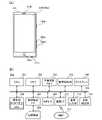
以下、図面を参照して本発明の好適な実施形態を説明する。図1(a)は、本実施形態に係る電子機器であるデジタルカメラ100(撮像装置)の前面斜視図(外観図)である。図1(b)は、デジタルカメラ100の背面斜視図(外観図)である。デジタルカメラ100は、全方位カメラ(全天球カメラ)である。 Preferred embodiments of the present invention will be described below with reference to the drawings. FIG. 1A is a front perspective view (external view) of a digital camera 100 (imaging device), which is an electronic device according to this embodiment. FIG. 1B is a rear perspective view (outside view) of the
バリア102aは、デジタルカメラ100の前方を撮影範囲とした前方カメラ部のための保護窓である。前方カメラ部は、例えば、デジタルカメラ100の前側の上下左右180度以上の広範囲を撮影範囲とする広角カメラ部である。バリア102bは、デジタルカメラ100の後方を撮影範囲とした後方カメラ部のための保護窓である。後方カメラ部は、例えば、デジタルカメラ100の後ろ側の上下左右180度以上の広範囲を撮影範囲とする広角カメラ部である。 The
表示部28は各種情報を表示する。シャッターボタン61は撮影指示を行うための操作部(操作部材)である。モード切替スイッチ60は各種モードを切り替えるための操作部である。接続I/F25は、接続ケーブルをデジタルカメラ100に接続するためのコネクタであり、接続ケーブルを用いて、スマートフォン、パーソナルコンピュータ、テレビなどの外部機器がデジタルカメラ100に接続される。操作部70は、ユーザーからの各種操作を受け付ける各種スイッチ、ボタン、ダイヤル、タッチセンサー等である。電源スイッチ72は、電源のオン/オフを切り替えるための押しボタンである。 The
発光部21は、発光ダイオード(LED)などの発光部材であり、デジタルカメラ100の各種状態を発光パターンや発光色によってユーザーに通知する。固定部40は、例えば三脚ネジ穴であり、三脚などの固定器具でデジタルカメラ100を固定して設置するために使用される。 The light-emitting
図1(c)は、デジタルカメラ100の構成例を示すブロック図である。 FIG. 1C is a block diagram showing a configuration example of the
バリア102aは、前方カメラ部の撮像系(撮影レンズ103a、シャッター101a、撮像部22a等)を覆うことにより、当該撮像系の汚れや破損を防止する。撮影レンズ103aは、ズームレンズやフォーカスレンズを含むレンズ群であり、広角レンズである。シャッター101aは、撮像部22aへの被写体光の入射量を調整する絞り機能を有するシャッターである。撮像部22aは、光学像を電気信号に変換するCCDやCMOS素子などで構成される撮像素子(撮像センサー)である。A/D変換器23aは、撮像部22aから出力されるアナログ信号をデジタル信号に変換する。なお、バリア102aを設けずに、撮影レンズ103aの外側の面が露出し、撮影レンズ103aによって他の撮像系(シャッター101aや撮像部22a)の汚れや破損を防止してもよい。 The
バリア102bは、後方カメラ部の撮像系(撮影レンズ103b、シャッター101b、撮像部22b等)を覆うことにより、当該撮像系の汚れや破損を防止する。撮影レンズ103bは、ズームレンズやフォーカスレンズを含むレンズ群であり、広角レンズである。シャッター101bは、撮像部22bへの被写体光の入射量を調整する絞り機能を有するシャッターである。撮像部22bは、光学像を電気信号に変換するCCDやCMOS素子などで構成される撮像素子である。A/D変換器23bは、撮像部22bから出力されるアナログ信号をデジタル信号に変換する。なお、バリア102bを設けずに、撮影レンズ103bの外側の面が露出し、撮影レンズ103bによって他の撮像系(シャッター101bや撮像部22b)の汚れや破損を防止してもよい。 The
撮像部22aと撮像部22bにより、VR(Virtual Reality)画像が撮像される。VR画像とは、VR表示(表示モード「VRビュー」で表示)をすることのできる画像であるものとする。VR画像には、全方位カメラ(全天球カメラ)で撮像した全方位画像(全天球画像)や、表示部に一度に表示できる表示範囲より広い映像範囲(有効映像範囲)を持つパノラマ画像などが含まれるものとする。VR画像には、静止画だけでなく、動画やライブビュー画像(カメラからほぼリアルタイムで取得した画像)も含まれる。VR画像は、最大で上下方向(垂直角度、天頂からの角度、仰角、俯角、高度角、ピッチ角)360度、左右方向(水平角度、方位角度、ヨー角)360度の視野分の映像範囲(有効映像範囲)を持つ。 A VR (Virtual Reality) image is captured by the
また、VR画像は、上下360度未満、左右360度未満であっても、通常のカメラで撮影可能な画角よりも広い広範な画角(視野範囲)、あるいは、表示部に一度に表示できる表示範囲より広い映像範囲(有効映像範囲)を持つ画像も含むものとする。例えば、左右方向(水平角度、方位角度)360度、天頂(zenith)を中心とした垂直角度210度の視野分(画角分)の被写体を撮影可能な全天球カメラで撮影された画像はVR画像の一種である。また、例えば、左右方向(水平角度、方位角度)180度、水平方向を中心とした垂直角度180度の視野分(画角分)の被写体を撮影可能なカメラで撮影された画像はVR画像の一種である。即ち、上下方向と左右方向にそれぞれ160度(±80度)以上の視野分の映像範囲を有しており、人間が一度に視認できる範囲よりも広い映像範囲を有している画像はVR画像の一種である。 In addition, even if the VR image is less than 360 degrees vertically and 360 degrees horizontally, it can be displayed at a wide angle of view (viewing range) that is wider than the angle of view that can be taken with a normal camera, or on the display unit at once. An image having a video range (effective video range) wider than the display range is also included. For example, an image captured by an omnidirectional camera capable of capturing a subject with a field of view (angle of view) of 360 degrees in the horizontal direction (horizontal angle, azimuth angle) and a vertical angle of 210 degrees centered on the zenith is It is a kind of VR image. Also, for example, an image captured by a camera capable of capturing a subject with a field of view (angle of view) of 180 degrees in the horizontal direction (horizontal angle, azimuth angle) and 180 degrees in the vertical angle centered on the horizontal direction is a VR image. It is one kind. That is, an image that has a video range of 160 degrees (±80 degrees) or more in the vertical direction and the horizontal direction and has a video range that is wider than the range that can be visually recognized by humans at once is a VR image. is a kind of
このVR画像をVR表示(表示モード「VRビュー」で表示)すると、左右回転方向に
表示装置(VR画像を表示する表示装置)の姿勢を変化させることで、左右方向(水平回転方向)には継ぎ目のない全方位の映像を視聴することができる。上下方向(垂直回転方向)には、真上(天頂)から±105度の範囲では継ぎ目のない全方位の映像を視聴することができるが、真上から105度を超える範囲は映像が存在しないブランク領域となる。VR画像は、「映像範囲が仮想空間(VR空間)の少なくとも一部である画像」とも言える。When this VR image is displayed in VR (displayed in the display mode "VR view"), by changing the posture of the display device (display device that displays the VR image) in the left and right rotation direction, the left and right direction (horizontal rotation direction) You can watch a seamless omnidirectional video. In the vertical direction (vertical rotation direction), seamless omnidirectional images can be viewed within a range of ±105 degrees from directly above (zenith), but no images exist within a range exceeding 105 degrees from directly above. It becomes a blank area. A VR image can also be said to be "an image whose video range is at least part of a virtual space (VR space)".
VR表示(VRビュー)とは、VR画像のうち、表示装置の姿勢に応じた視野範囲の映像を表示する、表示範囲を変更可能な表示方法(表示モード)である。表示装置であるスマートフォンなどで視聴する場合には、スマートフォンの向きに応じた視野範囲の映像を表示することになる。例えば、VR画像のうち、ある時点で左右方向に0度(特定の方位、例えば北)、上下方向に90度(天頂から90度、すなわち水平)を中心とした視野角(画角)の映像を表示しているものとする。この状態から、表示装置の姿勢を表裏反転させると(例えば、表示面を南向きから北向きに変更すると)、同じVR画像のうち、左右方向に180度(逆の方位、例えば南)、上下方向に90度(水平)を中心とした視野角の映像に、表示範囲が変更される。ユーザーがスマートフォンを持って視聴している場合で言えば、ユーザーがスマートフォンを北から南に向ければ(すなわち後ろを向けば)、スマートフォンに表示される映像も北の映像から南の映像に変わるということである。このようなVR表示によって、ユーザーに、視覚的にあたかもVR画像内(VR空間内)のその場にいるような感覚(没入感)を提供することができる。 VR display (VR view) is a display method (display mode) that allows the display range to be changed by displaying an image within a viewing range corresponding to the posture of the display device. When viewing on a display device such as a smartphone, the image is displayed within the viewing range according to the orientation of the smartphone. For example, in the VR image, at a certain point in time, the viewing angle (angle of view) is centered at 0 degrees in the horizontal direction (a specific direction, such as north) and 90 degrees in the vertical direction (90 degrees from the zenith, that is, horizontal). shall be displayed. From this state, if the posture of the display device is reversed (for example, if the display surface is changed from facing south to facing north), the same VR image can be displayed by 180 degrees in the left and right direction (opposite orientation, for example, south), and up and down. The display range is changed to an image with a viewing angle centered at 90 degrees (horizontal) in the direction. In the case where the user is viewing with a smartphone, if the user turns the smartphone from north to south (that is, turns back), the image displayed on the smartphone will change from the image of the north to the image of the south. That is. With such VR display, it is possible to provide the user with a sense (immersive feeling) as if he or she were visually present in the VR image (inside the VR space).
なお、VR画像の表示方法は上記に限るものではない。姿勢変化ではなく、タッチパネルや方向ボタンなどに対するユーザー操作に応じて、表示範囲を移動(スクロール)させてもよい。VR表示時(表示モード「VRビュー」時)において、姿勢変化による表示範囲の変更に加え、タッチパネルへのタッチムーブ、マウスなどへのドラッグ操作、方向ボタンの押下などに応じて表示範囲を変更できるようにしてもよい。 Note that the display method of the VR image is not limited to the above. The display range may be moved (scrolled) according to the user's operation on the touch panel, direction buttons, or the like, instead of changing the posture. When displaying VR (in the display mode "VR view"), in addition to changing the display range by changing the posture, the display range can be changed according to the touch and move on the touch panel, the drag operation on the mouse, the pressing of the direction button, etc. You may do so.
画像処理部24は、A/D変換器23aやA/D変換器23bからのデータ、又は、メモリ制御部15からのデータに対し所定の画素補間、縮小といったリサイズ処理や色変換処理を行う。また、画像処理部24は、撮像した画像データを用いて所定の演算処理を行う。システム制御部50は、画像処理部24により得られた演算結果に基づいて露光制御や測距制御を行う。これにより、TTL(スルー・ザ・レンズ)方式のAF(オートフォーカス)処理、AE(自動露出)処理、EF(フラッシュプリ発光)処理などが行われる。画像処理部24は更に、撮像した画像データを用いて所定の演算処理を行い、得られた演算結果に基づいてTTL方式のAWB(オートホワイトバランス)処理を行う。また、画像処理部24は、A/D変換器23aとA/D変換器23bから得られた2つの画像(2つの魚眼画像;2つの広角画像)に基本的な画像処理を施し、基本的な画像処理が施された2つの画像を合成する繋ぎ画像処理を行って、単一のVR画像を生成する。また、画像処理部24は、ライブビューでのVR表示時、あるいは再生時に、VR画像をVR表示するための画像切り出し処理、拡大処理、歪み補正などを行い、メモリ32のVRAMへ処理結果を描画するレンダリングを行う。 The
繋ぎ画像処理では、画像処理部24は、2つの画像の一方を基準画像、他方を比較画像として用いて、パターンマッチング処理によりエリア毎に基準画像と比較画像のずれ量を算出し、エリア毎のずれ量に基づいて、2つの画像を繋ぐ繋ぎ位置を検出する。画像処理部24は、検出した繋ぎ位置と各光学系のレンズ特性とを考慮して、幾何学変換により各画像の歪みを補正して、各画像を全天球形式(全天球イメージ形式)の画像に変換する。そして、画像処理部24は、全天球形式の2つの画像を合成(ブレンド)することで、1つの全天球画像(VR画像)を生成する。生成された全天球画像は、例えば正距円筒図法を用いた画像であり、全天球画像の各画素の位置は球体(VR空間)の表面の座標と対応
づけることができる(3Dマッピング)。In the stitching image processing, the
A/D変換器23a,23bからの出力データは、画像処理部24及びメモリ制御部15を介して、或いは、画像処理部24を介さずにメモリ制御部15を介してメモリ32に書き込まれる。メモリ32には、撮像部22a,22bによって得られA/D変換器23a,23bによりデジタルデータに変換された画像データなどを格納する。メモリ32には、通信部54を介して無線接続された外部機器(スマートフォンなど)に転送したり、接続I/F25から外部のディスプレイに出力したりするための画像データも格納する。メモリ32は、所定枚数の静止画像や所定時間の動画像および音声を格納するのに十分な記憶容量を備えている。 Output data from the A/
また、メモリ32は画像表示用のメモリ(ビデオメモリ)を兼ねている。メモリ32に格納されている画像表示用のデータは、通信部54を介して無線接続された外部機器(スマートフォンなど)に転送したり、接続I/F25から外部ディスプレイに出力したりすることが可能である。撮像部22a,22bで撮像され、画像処理部24で生成されたVR画像であって、メモリ32に蓄積されたVR画像を、通信部54を介して無線接続された外部機器(スマートフォンなど)に転送し、外部機器側で表示する。そうすることで、外部機器(スマートフォンなど)が電子ビューファインダとして機能し、リモートライブビュー表示(リモートLV表示)を行える。また、メモリ32に蓄積されたVR画像を外部ディスプレイに逐次転送して表示することでもリモートLV表示を行える。以下、リモートLV表示で表示される画像をリモートライブビュー画像(リモートLV画像)と称する。 The
不揮発性メモリ56は、電気的に消去・記録可能な記録媒体としてのメモリであり、例えばEEPROM等である。不揮発性メモリ56には、システム制御部50の動作用の定数、プログラム等が記録される。ここでいうプログラムとは、本実施形態にて後述する各種フローチャートを実行するためのコンピュータプログラムのことである。 The nonvolatile memory 56 is an electrically erasable/recordable recording medium, such as an EEPROM. Constants for the operation of the
システム制御部50は、少なくとも1つのプロセッサーまたは回路を有する制御部であり、デジタルカメラ100全体を制御する。システム制御部50は、前述した不揮発性メモリ56に記録されたプログラムを実行することで、後述する本実施形態の各処理を実現する。システムメモリ52は例えばRAMであり、システムメモリ52には、システム制御部50の動作用の定数、変数、不揮発性メモリ56から読み出したプログラム等が展開される。また、システム制御部50は、メモリ32、画像処理部24、メモリ制御部15等を制御することにより表示制御も行う。システムタイマー53は、各種制御に用いる時間や、内蔵された時計の時間を計測する計時部である。 The
モード切替スイッチ60、シャッターボタン61、操作部70、及び、電源スイッチ72は、システム制御部50に各種の動作指示を入力するために使用される。 The
モード切替スイッチ60は、システム制御部50の動作モードを静止画記録モード、動画撮影モード、再生モード、通信接続モード等のいずれかに切り替える。静止画記録モードに含まれるモードとして、オート撮影モード、オートシーン判別モード、マニュアルモード、絞り優先モード(Avモード)、シャッター速度優先モード(Tvモード)、プログラムAEモードがある。また、撮影シーン別の撮影設定となる各種シーンモード、カスタムモード等がある。モード切替スイッチ60より、ユーザーは、これらのモードのいずれかに直接切り替えることができる。あるいは、モード切替スイッチ60で撮影モードの一覧画面に一旦切り替えた後に、表示部28に表示された複数のモードのいずれかに、他の操作部材を用いて選択的に切り替えるようにしてもよい。同様に、動画撮影モードにも複数のモードが含まれていてもよい。 The
シャッターボタン61は、第1シャッタースイッチ62と第2シャッタースイッチ64を備える。第1シャッタースイッチ62は、シャッターボタン61の操作途中、いわゆる半押し(撮影準備指示)でONとなり第1シャッタースイッチ信号SW1を発生する。システム制御部50は、第1シャッタースイッチ信号SW1により、AF(オートフォーカス)処理、AE(自動露出)処理、AWB(オートホワイトバランス)処理、EF(フラッシュプリ発光)処理などの撮影準備動作を開始する。第2シャッタースイッチ64は、シャッターボタン61の操作完了、いわゆる全押し(撮影指示)でONとなり、第2シャッタースイッチ信号SW2を発生する。システム制御部50は、第2シャッタースイッチ信号SW2により、撮像部22a,22bからの信号読み出しから記録媒体150に画像データを書き込むまでの一連の撮影処理の動作を開始する。 The
なお、シャッターボタン61は全押しと半押しの2段階の操作ができる操作部材に限るものではなく、1段階の押下だけができる操作部材であってもよい。その場合は、1段階の押下によって撮影準備動作と撮影処理が連続して行われる。これは、半押しと全押しが可能なシャッターボタンを全押しした場合(第1シャッタースイッチ信号SW1と第2シャッタースイッチ信号SW2とがほぼ同時に発生した場合)と同じ動作である。 It should be noted that the
操作部70は、表示部28に表示される種々の機能アイコンや選択肢を選択操作することなどにより、場面ごとに適宜機能が割り当てられ、各種機能ボタンとして作用する。機能ボタンとしては、例えば終了ボタン、戻るボタン、画像送りボタン、ジャンプボタン、絞込みボタン、属性変更ボタン等がある。例えば、メニューボタンが押されると各種の設定可能なメニュー画面が表示部28に表示される。ユーザーは、表示部28に表示されたメニュー画面を見ながら操作部70を操作することで、直感的に各種設定を行うことができる。 The
電源スイッチ72は、電源のオン/オフを切り替えるための押しボタンである。電源制御部80は、電池検出回路、DC-DCコンバータ、通電するブロックを切り替えるスイッチ回路などにより構成され、電池の装着の有無、電池の種類、電池残量などの検出を行う。また、電源制御部80は、その検出結果及びシステム制御部50の指示に基づいてDC-DCコンバータを制御し、必要な電圧を必要な期間、記録媒体150を含む各部へ供給する。電源部30は、アルカリ電池やリチウム電池などの一次電池、NiCd電池やNiMH電池、Li電池などの二次電池、ACアダプター等からなる。 The
記録媒体I/F18は、メモリーカードやハードディスク等の記録媒体150とのインターフェースである。記録媒体150は、撮影された画像を記録するためのメモリーカード等の記憶部であり、半導体メモリや光ディスク、磁気ディスク等から構成される。記録媒体150は、デジタルカメラ100に対して着脱可能な交換記録媒体であってもよいし、デジタルカメラ100に内蔵された記録媒体であってもよい。 A recording medium I/
通信部54は、無線または有線ケーブルによって接続された外部機器との間で、映像信号や音声信号などの送受信を行う。通信部54は、無線LAN(Local Area Network)やインターネットにも接続可能である。通信部54は撮像部22a,22bで撮像され、画像処理部24で生成されたVR画像であって、メモリ32に蓄積されたVR画像を、通信部54を介して無線接続された外部機器(スマートフォンなど)に転送し、外部機器側で表示する。そうすることで、外部機器(スマートフォンなど)が電子ビューファインダとして機能し、リモートライブビュー表示(リモートLV表示)を行える。また、通信部54は、記録媒体150に記録された画像を送信可能であり、外部機器から画像やその他の各種情報を受信することができる。 The
姿勢検知部55は、重力方向に対するデジタルカメラ100の姿勢を検知する。姿勢検知部55で検知された姿勢に基づいて、撮像部22a,22bで撮影された画像が、デジタルカメラ100を横に構えて撮影された画像であるか、縦に構えて撮影された画像であるかを判別可能である。また、撮像部22a,22bで撮影された画像が、ヨー方向、ピッチ方向、ロール方向の3軸方向(回転方向)にデジタルカメラ100をどの程度傾けて撮影された画像であるかを判別可能である。システム制御部50は、姿勢検知部55で検知された姿勢に応じた向き情報を撮像部22a,22bで撮像されたVR画像の画像ファイルに付加したり、画像を回転(傾き補正(天頂補正)するように画像の向きを調整)して記録したりすることが可能である。加速度センサー、ジャイロセンサー、地磁気センサー、方位センサー、高度センサーなどのうちの1つのセンサーまたは複数のセンサーの組み合わせを、姿勢検知部55として用いることができる。姿勢検知部55を構成する加速度センサー、ジャイロセンサー、方位センサー等を用いて、デジタルカメラ100の動き(パン、チルト、持ち上げ、静止しているか否か等)を検知することも可能である。 The orientation detection unit 55 detects the orientation of the
マイク20は、動画であるVR画像(VR動画)の音声として記録されるデジタルカメラ100の周囲の音声を集音するマイクロフォンである。接続I/F25は、外部機器と接続して映像の送受信を行うための、HDMI(登録商標)ケーブルやUSBケーブルなどが接続される接続プラグである。 The
図2(a)は、表示制御装置200の外観図である。表示制御装置200は、例えばスマートフォンなどの表示装置である。ディスプレイ205は画像や各種情報を表示する表示部である。ディスプレイ205はタッチパネル206aと一体的に構成されており、ディスプレイ205の表示面へのタッチ操作を検出できるようになっている。表示制御装置200は、VR画像(VRコンテンツ)をディスプレイ205においてVR表示することが可能である。操作部206bは表示制御装置200の電源のオンとオフを切り替える操作を受け付ける電源ボタンである。操作部206cと操作部206dは音声出力部212から出力する音声のボリュームを増減するボリュームボタンである。操作部206eは、ディスプレイ205にホーム画面を表示させるためのホームボタンである。音声出力端子212aはイヤホンジャックであり、イヤホンや外部スピーカーなどに音声信号を出力する端子である。スピーカー212bは音声を出力する本体内蔵スピーカーである。 FIG. 2A is an external view of the
図2(b)は、表示制御装置200の構成例を示すブロック図である。内部バス250に対してCPU201、メモリ202、不揮発性メモリ203、画像処理部204、ディスプレイ205、操作部206、記録媒体I/F207、外部I/F209、及び、通信I/F210が接続されている。また、内部バス250に対して音声出力部212と姿勢検出部213も接続されている。内部バス250に接続される各部は、内部バス250を介して互いにデータのやりとりを行うことができるようにされている。 FIG. 2B is a block diagram showing a configuration example of the
CPU201は、表示制御装置200の全体を制御する制御部であり、少なくとも1つのプロセッサーまたは回路からなる。メモリ202は、例えばRAM(半導体素子を利用した揮発性のメモリなど)からなる。CPU201は、例えば、不揮発性メモリ203に格納されるプログラムに従い、メモリ202をワークメモリとして用いて、表示制御装置200の各部を制御する。不揮発性メモリ203には、画像データや音声データ、その他のデータ、CPU201が動作するための各種プログラムなどが格納される。不揮発性メモリ203は例えばフラッシュメモリやROMなどで構成される。 The
画像処理部204は、CPU201の制御に基づいて、不揮発性メモリ203や記録媒体208に格納された画像や、外部I/F209を介して取得した映像信号、通信I/F210を介して取得した画像などに対して各種画像処理を施す。画像処理部204が行う画像処理には、A/D変換処理、D/A変換処理、画像データの符号化処理、圧縮処理、
デコード処理、拡大/縮小処理(リサイズ)、ノイズ低減処理、色変換処理などが含まれる。また、全方位画像あるいは全方位ではないにせよ広範囲の映像を有する広範囲画像であるVR画像のパノラマ展開やマッピング処理、変換などの各種画像処理も行う。画像処理部204は特定の画像処理を施すための専用の回路ブロックで構成してもよい。また、画像処理の種別によっては画像処理部204を用いずにCPU201がプログラムに従って画像処理を施すことも可能である。Under the control of the
It includes decoding processing, enlargement/reduction processing (resize), noise reduction processing, color conversion processing, and the like. It also performs various image processing such as panorama development, mapping processing, and conversion of an omnidirectional image or a VR image that is a wide-range image having a wide-range image, even if it is not omnidirectional. The
ディスプレイ205は、CPU201の制御に基づいて、画像やGUI(Graphical User Interface)を構成するGUI画面などを表示する。CPU201は、プログラムに従い表示制御信号を生成し、ディスプレイ205に表示するための映像信号を生成してディスプレイ205に出力するように表示制御装置200の各部を制御する。ディスプレイ205は生成・出力された映像信号に基づいて映像を表示する。なお、表示制御装置200自体が備える構成としてはディスプレイ205に表示させるための映像信号を出力するためのインターフェースまでとし、ディスプレイ205は外付けのモニタ(テレビなど)で構成してもよい。また、ディスプレイ205は、通信I/F210を介して逐次転送される、デジタルカメラ100(撮像装置)で撮影されたVR画像を表示することで、電子ビューファインダとして機能し、リモートライブビュー表示(リモートLV表示)を行える。 The
操作部206は、キーボードなどの文字情報入力デバイスや、マウスやタッチパネルといったポインティングデバイス、ボタン、ダイヤル、ジョイスティック、タッチセンサー、タッチパッドなどを含む、ユーザー操作を受け付けるための入力デバイスである。本実施形態では、操作部206は、タッチパネル206a、操作部206b,206c,206d,206eを含む。 An
記録媒体I/F207には、メモリーカードやCD、DVDといった記録媒体208が着脱可能である。記録媒体I/F207は、CPU201の制御に基づき、装着された記録媒体208からのデータの読み出しや、記録媒体208に対するデータの書き込みを行う。外部I/F209は、外部機器と有線ケーブルや無線によって接続し、映像信号や音声信号の入出力を行うためのインターフェースである。通信I/F210は、外部機器やインターネット211などと通信して、ファイルやコマンドなどの各種データの送受信を行うためのインターフェースである。 A
音声出力部212は、動画や音楽データの音声や、操作音、着信音、各種通知音などを出力する。音声出力部212には、イヤホンなどを接続する音声出力端子212a、スピーカー212bが含まれるものとするが、音声出力部212は無線通信などで外部スピーカーに音声データを出力してもよい。 The
姿勢検出部213は、重力方向に対する表示制御装置200の姿勢(傾き)や、ヨー方向、ピッチ方向、ロール方向の各軸に対する表示制御装置200の姿勢を検出する。姿勢検出部213で検出された姿勢に基づいて、表示制御装置200が横に保持されているか、縦に保持されているか、上に向けられたか、下に向けられたか、斜めの姿勢になったかなどを判別可能である。また、ヨー方向、ピッチ方向、ロール方向などの回転方向における表示制御装置200の傾きの有無や大きさ、当該回転方向に表示制御装置200が回転したかなどを判別可能である。加速度センサー、ジャイロセンサー、地磁気センサー、方位センサー、高度センサーなどのうちの1つのセンサーまたは複数のセンサーの組み合わせを、姿勢検出部213として用いることができる。 The
上述したように、操作部206にはタッチパネル206aが含まれる。タッチパネル206aは、ディスプレイ205に重ね合わせて平面的に構成され、接触された位置に応じ
た座標情報が出力されるようにした入力デバイスである。CPU201はタッチパネル206aへの以下の操作、あるいは状態を検出できる。
・タッチパネル206aにタッチしていなかった指やペンが新たにタッチパネル206aにタッチしたこと、すなわちタッチの開始(以下、タッチダウン(Touch-Down)と称する)
・タッチパネル206aを指やペンがタッチしている状態(以下、タッチオン(Touch-On)と称する)
・指やペンがタッチパネル206aをタッチしたまま移動していること(以下、タッチムーブ(Touch-Move)と称する)
・タッチパネル206aへタッチしていた指やペンがタッチパネル206aから離れたこと、すなわちタッチの終了(以下、タッチアップ(Touch-Up)と称する)
・タッチパネル206aに何もタッチしていない状態(以下、タッチオフ(Touch-Off)と称する)As described above, the
- The
A state in which a finger or pen is touching the
・The finger or pen is moving while touching the
- The finger or pen touching the
A state in which nothing is touched on the
タッチダウンが検出されると、同時にタッチオンも検出される。タッチダウンの後、タッチアップが検出されない限りは、通常はタッチオンが検出され続ける。タッチムーブが検出された場合も、同時にタッチオンが検出される。タッチオンが検出されていても、タッチ位置が移動していなければタッチムーブは検出されない。タッチしていた全ての指やペンがタッチアップしたことが検出されると、タッチオフが検出される。 When touchdown is detected, touchon is also detected at the same time. After touchdown, touchon continues to be detected unless touchup is detected. Touch-on is detected at the same time when touch-move is detected. Even if touch-on is detected, touch-move is not detected if the touch position does not move. Touch-off is detected when it is detected that all the fingers and pens that were in touch have touched up.
これらの操作・状態や、タッチパネル206a上に指やペンがタッチしている位置座標は内部バスを通じてCPU201に通知され、CPU201は通知された情報に基づいてタッチパネル206a上にどのような操作(タッチ操作)が行われたかを判定する。タッチムーブについてはタッチパネル206a上で移動する指やペンの移動方向についても、位置座標の変化に基づいて、タッチパネル206a上の垂直成分・水平成分毎に判定できる。所定距離以上をタッチムーブしたことが検出された場合はスライド操作が行われたと判定するものとする。 The
タッチパネル206a上に指をタッチしたままある程度の距離だけ素早く動かして、そのまま離すといった操作をフリックと呼ぶ。フリックは、言い換えればタッチパネル206a上を指ではじくように素早くなぞる操作である。所定距離以上を、所定速度以上でタッチムーブしたことが検出され、そのままタッチアップが検出されるとフリックが行われたと判定できる(スライド操作に続いてフリックがあったものと判定できる)。 An operation of touching the
更に、複数箇所(例えば2点)を同時にタッチして、互いのタッチ位置を近づけるタッチ操作をピンチイン、互いのタッチ位置を遠ざけるタッチ操作をピンチアウトと称する。ピンチアウトとピンチインを総称してピンチ操作(あるいは単にピンチ)と称する。タッチパネル206aは、抵抗膜方式や静電容量方式、表面弾性波方式、赤外線方式、電磁誘導方式、画像認識方式、光センサー方式など、様々な方式のタッチパネルのうちいずれの方式のものを用いてもよい。タッチパネルに対する接触があったことでタッチがあったと検出する方式や、タッチパネルに対する指やペンの接近があったことでタッチがあったと検出する方式があるが、いずれの方式でもよい。 Further, a touch operation of simultaneously touching a plurality of points (for example, two points) to bring the touch positions closer to each other is called pinch-in, and a touch operation of moving the touch positions away from each other is called pinch-out. Pinch-out and pinch-in are collectively called pinch operation (or simply pinch). The
図3(a),3(b)は、表示制御装置200におけるリモートライブビュー表示の一例を示す。本実施形態において、リモートライブビュー表示の表示形式には、全天球(全方位)イメージ形式とズームビュー形式がある。全天球イメージ形式は、デジタルカメラ100(撮像装置)で撮像されたVR画像の全体を正距円筒図法を用いてディスプレイ205に表示する形式、所謂パノラマ形式である。つまり、全天球イメージ形式では、デジタルカメラ100で撮像されたVR画像がそのまま表示される。図3(a)は、全天球イメージ形式のリモートライブビュー表示の一例を示す。ズームビュー形式は、デジタルカ
メラ100で撮像されたVR画像から一部の領域(範囲)を切り出してディスプレイ205に表示する形式である。ズームビュー形式では、一般的に、ユーザーが表示制御装置200(スマートフォン)で指示した領域に基づいて一部の領域が切り出されて表示される。図3(b)は、ズームビュー形式のリモートライブビュー表示の一例を示す。ユーザーは、操作部206を用いて、全天球イメージ形式の表示モードとズームビュー形式の表示モードとの間で表示モードを切り替えることが可能である。なお、表示形式は全天球イメージ形式とズームビュー形式に限られず、他の形式の表示モードが設定できてもよい。3A and 3B show an example of remote live view display in the
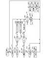
図4は、デジタルカメラ100の全体処理の一例を示すフローチャートである。この処理は、システム制御部50が不揮発性メモリ56に記録されたプログラムをシステムメモリ52に展開して実行することにより実現される。デジタルカメラ100の電源が入ると図4の処理が開始する。 FIG. 4 is a flow chart showing an example of overall processing of the
S401では、システム制御部50は、表示制御装置200の表示形式(表示モード)の変更が通知されたか否かを判断する。通知されたと判断した場合はS402に進み、そうでない場合はS403に進む。S402では、システム制御部50は、通知された表示形式(変更後の表示形式;現在の表示形式)を示す形式情報をシステムメモリ52に格納する(システムメモリ52に格納された形式情報の更新)。S401の処理は、形式情報を受信(取得)したか否かを判断する処理でもある。本実施形態では、形式情報は、表示制御装置200から通信部54を介して取得される。 In S401, the
S403では、システム制御部50は、表示制御装置200の表示範囲(撮像された画像のうち、リモートライブビュー表示で表示される範囲)の変更が通知されたか否かを判断する。通知されたと判断した場合はS404に進み、そうでない場合はS405に進む。S404では、システム制御部50は、通知された表示範囲(変更後の表示範囲;現在の表示範囲)に関する範囲情報をシステムメモリ52に格納する(システムメモリ52に格納された範囲情報の更新)。範囲情報は、例えば、撮像されたVR画像(正距円筒図法)を3Dマッピングした際の、視点の方向と視野角(画角)とを表す。範囲情報は表示範囲を示す他の情報であってもよい。S403の処理は、範囲情報を受信(取得)したか否かを判断する処理でもある。本実施形態では、範囲情報は、表示制御装置200から通信部54を介して取得される。 In S403, the
S405では、システム制御部50は、ユーザーからの撮影指示(撮影操作)があったか否かを判断する。撮影指示があったと判断した場合はS406に進み、そうでない場合はS411に進む。S406では、システム制御部50は、撮像されたVR画像(正距円筒図法)のファイルを記録媒体150に記録する。 In S405, the
S407では、システム制御部50は、システムメモリ52に格納されている形式情報に応じて、表示制御装置200の表示形式が、撮像されたVR画像の一部の範囲を表示する形式(ズームビュー形式)であるか否かを判断する。ズームビュー形式であると判断した場合はS409に進み、そうでない場合(全天球イメージ形式の場合)はS408に進む。 In S407, the
S408では、システム制御部50は、撮像されたVR画像に基づいて、S406で記録されたファイルにサムネイル画像を記録(生成して記録)する。具体的には、撮像されたVR画像(正距円筒図法)の全体を表すサムネイル画像(VR画像を縮小した画像など)をファイルに記録する。 In S408, the
S409では、システム制御部50は、撮像されたVR画像(正距円筒図法)を3Dマッピングし、システムメモリ52に格納されている範囲情報(視点の方向と視野角(画角
))に応じて、VR画像から表示範囲を切り出す。S410では、システム制御部50は、S409で切り出した画像(表示範囲)に基づいて、S406で記録されたファイルにサムネイル画像を記録(生成して記録)する。具体的には、表示範囲を表すサムネイル画像(表示範囲の画像を縮小した画像など)をファイルに記録する。In S<b>409 , the
S411では、システム制御部50は、ユーザーからデジタルカメラ100の停止指示(停止操作)があったか否かを判断する。停止指示があったと判断した場合は、システム制御部50が種々の処理を行うことで、デジタルカメラ100を停止する(デジタルカメラ100の電源を切る)。そして、図4の全体処理を終了する。そうでない場合はS412に進む。 In S<b>411 , the
S412では、システム制御部50は、撮像部22aを用いてフロント画像を取得(撮像)する。S413では、システム制御部50は、撮像部22bを用いてリア画像を取得(撮像)する。S414では、システム制御部50は、画像処理部24を用いて、S412とS413で取得された2つの画像を合成することにより、単一のVR画像(正距円筒図法)を生成する。S415では、システム制御部50は、S414で生成したVR画像(正距円筒図法)を、通信部54を介して表示制御装置200に送信する。 In S412, the
図5は、表示制御装置200のリモートライブビュー処理の一例を示すフローチャートである。この処理は、CPU201が不揮発性メモリ203に記録されたプログラムをメモリ202に展開して実行することにより実現される。表示制御装置200の電源が入り、デジタルカメラ100で撮像されたVR画像のリモートライブビュー表示を行う表示モードが表示制御装置200に設定されると、図5の処理が開始する。 FIG. 5 is a flowchart showing an example of remote live view processing of the
S501では、CPU201は、撮像されたVR画像(正距円筒図法)をデジタルカメラ100(撮像装置)から受信したか否かを判断する。受信したと判断した場合はS509に進み、そうでない場合はS502に進む。本実施形態では、VR画像は、デジタルカメラ100から通信I/F210を介して受信される。 In S501, the
S502では、CPU201は、ユーザーからの形式変更指示(表示形式を変更する指示;形式変更操作)があったか否かを判断する。形式変更指示があったと判断した場合はS503に進み、そうでない場合はS506に進む。 In S502, the
S503では、CPU201は、現在の表示形式が全天球イメージ形式であるか否かを判断する。全天球イメージ形式であると判断した場合はS504に進み、そうでない場合はS505に進む。 In S503, the
S504では、CPU201は、表示形式をズームビュー形式に切り替えるよう、ズームビュー形式を示す形式情報をメモリ202に格納する(メモリ202に格納された形式情報の更新)。さらに、CPU201は、ズームビュー形式への表示形式の変更をデジタルカメラ100に通知するよう、ズームビュー形式を示す形式情報を、通信I/F210を介してデジタルカメラ100に送信する。 In S504, the
S505では、CPU201は、表示形式を全天球イメージ形式に切り替えるよう、全天球イメージ形式を示す形式情報をメモリ202に格納する(メモリ202に格納された形式情報の更新)。さらに、CPU201は、全天球イメージ形式への表示形式の変更をデジタルカメラ100に通知するよう、全天球イメージ形式を示す形式情報を、通信I/F210を介してデジタルカメラ100に送信する。 In S505, the
S506では、CPU201は、ユーザーからの範囲変更指示(表示範囲を変更する指
示;範囲変更操作)があったか否かを判断する。範囲変更指示があったと判断した場合はS607に進み、そうでない場合はS501に進む。S507では、CPU201は、現在の表示形式がズームビュー形式であるか否かを判断する。ズームビュー形式であると判断した場合はS508に進み、そうでない場合はS501に進む。S508では、CPU201は、表示範囲を更新するよう、変更後の表示範囲に関する範囲情報をメモリ202に格納する(メモリ202に格納された範囲情報の更新)。さらに、CPU201は、表示範囲の変更をデジタルカメラ100に通知するよう、現在の表示範囲を示す範囲情報を、通信I/F210を介してデジタルカメラ100に送信する。In S506, the
S509では、CPU201は、現在の表示形式が全天球イメージ形式であるか否かを判断する。全天球イメージ形式であると判断した場合はS510に進み、そうでない場合はS511に進む。 In S509, the
S510では、CPU201は、デジタルカメラ100から受信したVR画像(正距円筒図法)をそのままリモートライブビュー画像としてディスプレイ205に表示する(ディスプレイ205における画像表示の更新)。 In S510, the
S511では、CPU201は、範囲情報(視点の方向と視野角(画角))をメモリ202から読み出す。S512では、CPU201は、デジタルカメラ100から受信したVR画像(正距円筒図法)を3Dマッピングし、S511で読み出した範囲情報に応じて、VR画像から表示範囲を切り出す。S513では、CPU201は、S512で切り出した表示範囲の画像をモートライブビュー画像としてディスプレイ205に表示する(ディスプレイ205における画像表示の更新)。 In S<b>511 , the
以上述べたように、本実施形態によれば、撮像されたVR画像の一部の範囲がディスプレイにライブビュー画像として表示されている場合に、ライブビュー画像の範囲に対応するサムネイル画像がファイルに記録される。このため、撮影(記録)されたVR画像をPC(パーソナルコンピュータ)などで確認する場合には、図6に示すように、VR画像のファイルのサムネイル画像として、ユーザーが撮影時に確認していた範囲の画像が表示される。これにより、サムネイル画像の印象が、撮影時におけるリモートライブビュー表示の表示範囲の印象と合い、ユーザーは、サムネイル画像を見るだけで、各ファイルがどのシーンを撮影したVR画像のファイルであるかを容易に把握できる。 As described above, according to the present embodiment, when a range of a captured VR image is displayed as a live-view image on the display, a thumbnail image corresponding to the range of the live-view image is stored in the file. Recorded. For this reason, when confirming a captured (recorded) VR image on a PC (personal computer) or the like, as shown in FIG. image is displayed. As a result, the impression of the thumbnail image matches the impression of the display range of the remote live view display at the time of shooting, and the user can tell which scene the VR image file of each file is just by looking at the thumbnail image. Easy to grasp.
なお、撮像された画像がVR画像である場合の例を説明したが、VR画像でない画像が撮像される場合においても同様の処理により同様の効果を得ることができる。また、リモートライブビュー表示が行われる例を説明したが、本実施形態に係る電子機器(デジタルカメラ100)に、ライブビュー表示を実行可能なディスプレイを設けてもよい。 Although an example in which the captured image is a VR image has been described, similar effects can be obtained by similar processing even when an image other than a VR image is captured. Further, although an example in which remote live view display is performed has been described, the electronic device (digital camera 100) according to this embodiment may be provided with a display capable of performing live view display.
なお、表示制御装置200からデジタルカメラ100に形式情報と範囲情報が送信され、それらに基づいてサムネイル画像が生成される例を説明したが、これに限られない。例えば、デジタルカメラ100が、撮影を行うタイミングを表示制御装置200に通知し、表示制御装置200が、表示しているリモートライブビュー画像をデジタルカメラ100に送信してもよい。そして、デジタルカメラ100が、受信したリモートライブビュー画像に基づいてサムネイル画像を記録してもよい。図7,8は、そのような処理の一例を示すフローチャートである。 Although an example has been described in which format information and range information are transmitted from the
図7は、デジタルカメラ100の全体処理の一例を示すフローチャートである。この処理は、システム制御部50が不揮発性メモリ56に記録されたプログラムをシステムメモリ52に展開して実行することにより実現される。デジタルカメラ100の電源が入ると図7の処理が開始する。 FIG. 7 is a flow chart showing an example of overall processing of the
S701では、システム制御部50は、ユーザーからの撮影指示があったか否かを判断する。撮影指示があったと判断した場合はS702に進み、そうでない場合はS704に進む。S702では、システム制御部50は、撮像されたVR画像(正距円筒図法)のファイルを記録媒体150に記録する。S703では、システム制御部50は、通信部54を介して表示制御装置200に、リモートライブビュー画像の送信を要求する。 In S701, the
S704では、システム制御部50は、リモートライブビュー画像を表示制御装置200から受信したか否かを判断する。受信したと判断した場合はS705に進み、そうでない場合はS706に進む。本実施形態では、リモートライブビューは、表示制御装置200から通信部54を介して受信される。S705では、システム制御部50は、表示制御装置200から受信したリモートライブビュー画像に基づいて、S702で記録されたファイルにサムネイル画像を記録(生成して記録)する。具体的には、受信したリモートライブビュー画像を表すサムネイル画像(リモートライブビュー画像を縮小した画像など)をファイルに記録する。 In S<b>704 , the
S706では、システム制御部50は、ユーザーからデジタルカメラ100の停止指示があったか否かを判断する。停止指示があったと判断した場合は、システム制御部50が種々の処理を行うことで、デジタルカメラ100を停止する。そして、図7の全体処理を終了する。そうでない場合はS707に進む。 In S<b>706 , the
S707では、システム制御部50は、撮像部22aを用いてフロント画像を取得(撮像)する。S708では、システム制御部50は、撮像部22bを用いてリア画像を取得(撮像)する。S709では、システム制御部50は、画像処理部24を用いて、S707とS708で取得された2つの画像を合成することにより、単一のVR画像(正距円筒図法)を生成する。S710では、システム制御部50は、S709で生成したVR画像(正距円筒図法)を、通信部54を介して表示制御装置200に送信する。 In S707, the
図8は、表示制御装置200のリモートライブビュー処理の一例を示すフローチャートである。この処理は、CPU201が不揮発性メモリ203に記録されたプログラムをメモリ202に展開して実行することにより実現される。表示制御装置200の電源が入り、デジタルカメラ100で撮像されたVR画像のリモートライブビュー表示を行う表示モードが表示制御装置200に設定されると、図8の処理が開始する。 FIG. 8 is a flowchart showing an example of remote live view processing of the
S801では、CPU201は、撮像されたVR画像(正距円筒図法)をデジタルカメラ100(撮像装置)から受信したか否かを判断する。受信したと判断した場合はS809に進み、そうでない場合はS802に進む。 In S801, the
S802では、CPU201は、ユーザーからの形式変更指示があったか否かを判断する。形式変更指示があったと判断した場合はS803に進み、そうでない場合はS806に進む。 In S802, the
S803では、CPU201は、現在の表示形式が全天球イメージ形式であるか否かを判断する。全天球イメージ形式であると判断した場合はS804に進み、そうでない場合はS805に進む。S804では、CPU201は、表示形式をズームビュー形式に切り替えるよう、ズームビュー形式を示す形式情報をメモリ202に格納する(メモリ202に格納された形式情報の更新)。S805では、CPU201は、表示形式を全天球イメージ形式に切り替えるよう、全天球イメージ形式を示す形式情報をメモリ202に格納する(メモリ202に格納された形式情報の更新)。 In S803, the
S806では、CPU201は、ユーザーからの範囲変更指示があったか否かを判断する。範囲変更指示があったと判断した場合はS807に進み、そうでない場合はS814に進む。 In S806, the
S807では、CPU201は、現在の表示形式がズームビュー形式であるか否かを判断する。ズームビュー形式であると判断した場合はS808に進み、そうでない場合はS801に進む。S808では、CPU201は、表示範囲を更新するよう、変更後の表示範囲に関する範囲情報をメモリ202に格納する(メモリ202に格納された範囲情報の更新)。 In S807, the
S809では、CPU201は、現在の表示形式が全天球イメージ形式であるか否かを判断する。全天球イメージ形式であると判断した場合はS810に進み、そうでない場合はS811に進む。 In S809, the
S810では、CPU201は、デジタルカメラ100から受信したVR画像(正距円筒図法)をそのままリモートライブビュー画像としてディスプレイ205に表示する(ディスプレイ205における画像表示の更新)。さらに、CPU201は、現在のリモートライブビュー画像をメモリ202に格納する(メモリ202に格納されているリモートライブビュー画像の更新)。 In S810, the
S811では、CPU201は、範囲情報(視点の方向と視野角(画角))をメモリ202から読み出す。S812では、CPU201は、デジタルカメラ100から受信したVR画像(正距円筒図法)を3Dマッピングし、S811で読み出した範囲情報に応じて、VR画像から表示範囲を切り出す。S813では、CPU201は、S812で切り出した表示範囲の画像をモートライブビュー画像としてディスプレイ205に表示する(ディスプレイ205における画像表示の更新)。さらに、CPU201は、現在のリモートライブビュー画像をメモリ202に格納する(メモリ202に格納されているリモートライブビュー画像の更新)。 In S<b>811 , the
S814では、CPU201は、デジタルカメラ100から通信I/F210を介してリモートライブビュー画像の送信が要求されたか否かを判断する。要求されたと判断した場合はS815に進み、そうでない場合はS801に進む。S815では、CPU201は、リモートライブビュー画像をメモリ読み出し、通信I/F210を介してデジタルカメラ100に送信する。 In S<b>814 , the
なお、システム制御部50は、動画を撮影するように、ユーザーからの記録開始指示(撮影指示)に応答して、撮像(取得)された動画のファイルの記録を開始し、ユーザーからの記録停止指示に応答してファイルの記録を停止してもよい。その場合には、システム制御部50は、ファイル記録中のライブビュー画像の範囲に対応するサムネイル画像をファイルに記録する。こうすることで、ファイル記録中のライブビュー画像はユーザーの印象に残っている可能性が高いため、ユーザーは、サムネイル画像を見るだけで、各ファイルがどのシーンを撮影した動画のファイルであるかを容易に把握できる。記録開始指示または記録停止指示があったタイミングでのライブビュー画像は特にユーザーの印象に残っている可能性が高いため、そのようなタイミングでのライブビュー画像の範囲に対応するサムネイル画像をファイルに記録することが好ましい。 Note that the
なお、リモートライブビュー画像に基づくサムネイル画像をファイルに記録する例を説明したが、リモートライブビュー画像の範囲に関する範囲情報を、ファイルを再生する際に最初に表示される範囲に関する初期再生情報としてファイルに記録してもよい。そうすることで、再生開始時の表示範囲の印象が、撮影時におけるリモートライブビュー表示の
表示範囲の印象と合い、ユーザーは、再生したファイルがどのシーンを撮影したVR画像のファイルであるかを容易に把握できる。図9,10は、そのような処理の一例を示すフローチャートである。An example of recording a thumbnail image based on a remote live view image in a file has been described, but the range information about the range of the remote live view image is used as initial playback information about the range to be displayed first when the file is played back. may be recorded in By doing so, the impression of the display range at the start of playback will match the impression of the display range of the remote live view display at the time of shooting, and the user will be able to tell which scene the playback file is a VR image file of. Easy to grasp. 9 and 10 are flow charts showing an example of such processing.
図9は、デジタルカメラ100の全体処理の一例を示すフローチャートである。この処理は、システム制御部50が不揮発性メモリ56に記録されたプログラムをシステムメモリ52に展開して実行することにより実現される。デジタルカメラ100の電源が入ると図9の処理が開始する。 FIG. 9 is a flow chart showing an example of overall processing of the
S901では、システム制御部50は、表示制御装置200の表示形式の変更が通知されたか否かを判断する。通知されたと判断した場合はS902に進み、そうでない場合はS903に進む。S902では、システム制御部50は、通知された表示形式(変更後の表示形式;現在の表示形式)を示す形式情報をシステムメモリ52に格納する(システムメモリ52に格納された形式情報の更新)。 In S<b>901 , the
S903では、システム制御部50は、表示制御装置200の表示範囲の変更が通知されたか否かを判断する。通知されたと判断した場合はS904に進み、そうでない場合はS905に進む。S904では、システム制御部50は、通知された表示範囲(変更後の表示範囲;現在の表示範囲)に関する範囲情報(視点の方向と視野角(画角))をシステムメモリ52に格納する(システムメモリ52に格納された範囲情報の更新)。 In S903, the
S905では、システム制御部50は、ユーザーからの撮影指示があったか否かを判断する。撮影指示があったと判断した場合はS906に進み、そうでない場合はS910に進む。S906では、システム制御部50は、撮像されたVR画像(正距円筒図法)のファイルを記録媒体150に記録する。 In S<b>905 , the
S907では、システム制御部50は、システムメモリ52に格納されている形式情報に応じて、表示制御装置200の表示形式がズームビュー形式であるか否かを判断する。ズームビュー形式であると判断した場合はS909に進み、そうでない場合はS908に進む。S908では、システム制御部50は、撮像されたVR画像のうち、デジタルカメラ100の正面方向などの所定の方向を撮像した範囲に関する初期再生情報(視点の方向と視野角(画角))を、S906で記録されたファイルに記録する。S909では、システム制御部50は、システムメモリ52に格納されている範囲情報(視点の方向と視野角(画角))を、初期再生情報として、S906で記録されたファイルに記録する。 In S<b>907 , the
S910では、システム制御部50は、ユーザーからデジタルカメラ100の停止指示があったか否かを判断する。停止指示があったと判断した場合は、システム制御部50が種々の処理を行うことで、デジタルカメラ100を停止する。そして、図9の全体処理を終了する。そうでない場合はS911に進む。 In S<b>910 , the
S911では、システム制御部50は、撮像部22aを用いてフロント画像を取得(撮像)する。S912では、システム制御部50は、撮像部22bを用いてリア画像を取得(撮像)する。S913では、システム制御部50は、画像処理部24を用いて、S911とS912で取得された2つの画像を合成することにより、単一のVR画像(正距円筒図法)を生成する。S914では、システム制御部50は、S913で生成したVR画像(正距円筒図法)を、通信部54を介して表示制御装置200に送信する。 In S911, the
図10は、表示制御装置200の再生処理(ファイルを再生する処理)の一例を示すフローチャートである。この処理は、CPU201が不揮発性メモリ203に記録されたプログラムをメモリ202に展開して実行することにより実現される。表示制御装置200
の電源が入り、記録媒体208に格納されているファイルの再生がユーザーから指示されると、図10の処理が開始する。FIG. 10 is a flowchart showing an example of reproduction processing (file reproduction processing) of the
is turned on, and the user instructs to reproduce a file stored in the
S1001では、CPU201は、再生対象のファイルから初期再生情報(視点の方向と視野角(画角))を取得する。S1002では、CPU201は、再生対象のファイルに記録されているVR画像のうち、S1001で取得した初期再生情報に応じた表示範囲をディスプレイ205に表示する。撮影時の表示形式が全天球イメージ形式であった場合には、全天球イメージ形式でVR画像が表示される。撮影時の表示形式がズームビュー形式であった場合には、撮影時のリモートライブビュー表示で表示されていた表示範囲が表示されるように、VR画像の一部の範囲が切り出されて表示される。 In S1001, the
なお、システム制御部50やCPU201が行うものとして説明した上述の各種制御は、1つのハードウェアが行ってもよいし、複数のハードウェア(例えば、複数のプロセッサーや回路)が処理を分担することで、装置全体の制御を行ってもよい。同様に、CPU201が行うものとして説明した上述の各種制御は、1つのハードウェアが行ってもよいし、複数のハードウェア(例えば、複数のプロセッサーや回路)が処理を分担することで、装置全体の制御を行ってもよい。 The above-described various controls performed by the
また、本発明をその好適な実施形態に基づいて詳述してきたが、本発明はこれら特定の実施形態に限られるものではなく、この発明の要旨を逸脱しない範囲の様々な形態も本発明に含まれる。さらに、上述した各実施形態は本発明の一実施形態を示すものにすぎず、各実施形態を適宜組み合わせることも可能である。 Moreover, although the present invention has been described in detail based on its preferred embodiments, the present invention is not limited to these specific embodiments, and various forms within the scope of the present invention can be applied to the present invention. included. Furthermore, each embodiment described above merely shows one embodiment of the present invention, and it is also possible to combine each embodiment as appropriate.
また、上述した実施形態においては、本発明をデジタルカメラに適用した場合を例にして説明したが、これはこの例に限定されず、撮像された画像のファイルを記録することのできる電子機器であれば適用可能である。例えば、本発明は、パーソナルコンピュータやPDA、携帯電話端末や携帯型の画像ビューワ、プリンタ装置、デジタルフォトフレーム、音楽プレーヤー、ゲーム機、電子ブックリーダー、映像プレーヤーなどに適用可能である。また、本発明は、スマートフォン、テレビジョン装置、投影装置、タブレット端末、AIスピーカー、家電装置、車載装置、医療機器などにも適用可能である。 Further, in the above-described embodiments, the case where the present invention is applied to a digital camera has been described as an example, but the present invention is not limited to this example, and can be an electronic device capable of recording files of captured images. applicable if available. For example, the present invention can be applied to personal computers, PDAs, mobile phone terminals, portable image viewers, printers, digital photo frames, music players, game machines, electronic book readers, video players, and the like. The present invention can also be applied to smartphones, television devices, projection devices, tablet terminals, AI speakers, home appliances, vehicle-mounted devices, medical devices, and the like.
(その他の実施形態)
本発明は、上述の実施形態の1以上の機能を実現するプログラムを、ネットワーク又は記憶媒体を介してシステム又は装置に供給し、そのシステム又は装置のコンピュータにおける1つ以上のプロセッサーがプログラムを読出し実行する処理でも実現可能である。また、1以上の機能を実現する回路(例えば、ASIC)によっても実現可能である。(Other embodiments)
The present invention supplies a program that implements one or more functions of the above-described embodiments to a system or device via a network or a storage medium, and one or more processors in the computer of the system or device reads and executes the program. It can also be realized by processing to It can also be implemented by a circuit (for example, ASIC) that implements one or more functions.
100:デジタルカメラ 22a,22b:撮像部 50:システム制御部 100:
Claims (8)
Translated fromJapanese表示手段を有する外部機器からライブビュー画像を取得する第2取得手段と、
ユーザーからの撮影指示に応答して、前記第1取得手段により取得された前記画像のファイルを記憶部に記録するように制御する制御手段と、
を有し、
前記撮像された画像の一部の範囲が前記表示手段に前記ライブビュー画像として表示されている場合に、前記制御手段は、さらに、前記ライブビュー画像に基づいて、前記ライブビュー画像の範囲に対応するサムネイル画像を前記ファイルに記録するように制御することを特徴とする電子機器。a first acquisition means for acquiring a captured image;
a second obtaining means for obtaining a live view image from an external device having a display means;
a control means for controlling to record the file of the image acquired by the first acquisition means in a storage unit in response to a photographing instruction from a user;
has
When a partial range of the captured image is displayed asthe live view image on thedisplay means, the control means further corresponds to the range ofthe live view image based on the live view image. an electronic device that controls such that a thumbnail image to be displayed is recorded in the file.
前記撮影指示である記録開始指示に応答して、前記第1取得手段により取得された動画のファイルの記録を開始し、
前記ユーザーからの記録停止指示に応答して、前記ファイルの記録を停止し、
前記記録開始指示があったタイミングでのライブビュー画像の範囲に対応するサムネイル画像を記録するように制御する
ことを特徴とする請求項1に記載の電子機器。The control means is
starting recording of the moving image file acquired by the first acquisition means in response to a recording start instruction, which is the shooting instruction;
Stop recording the file in response to a recording stop instruction from the user;
2. The electronic device accordingto claim 1, wherein control is performed so as to record a thumbnail image corresponding to the range of the live view image at the timing when the recording start instruction is given.
前記撮影指示である記録開始指示に応答して、前記第1取得手段により取得された動画のファイルの記録を開始し、
前記ユーザーからの記録停止指示に応答して、前記ファイルの記録を停止し、
前記記録停止指示があったタイミングでのライブビュー画像の範囲に対応するサムネイル画像を記録するように制御する
ことを特徴とする請求項1または2に記載の電子機器。The control means is
starting recording of the moving image file acquired by the first acquisition means in response to a recording start instruction, which is the shooting instruction;
Stop recording the file in response to a recording stop instruction from the user;
3. The electronic device according to claim1, wherein control is performed so as to record a thumbnail image corresponding to the range of the live view image at the timing when the recording stop instruction is issued.
するように制御する
ことを特徴とする請求項1~3のいずれか1項に記載の電子機器。When a partial range of the captured image is displayed as a live view image on the display means, the control means further displays information about the range of the live view image when reproducing the file. 4. The electronic device according to any one of claims 1 to3 , wherein control is performed so that information relating to the range to be displayed first is recorded in the file.
ことを特徴とする請求項1~4のいずれか1項に記載の電子機器。The electronic device according to any one of claims 1 to4 , wherein the captured image is a VR image.
表示手段を有する外部機器からライブビュー画像を取得する第2取得ステップと、
ユーザーからの撮影指示に応答して、前記第1取得ステップにおいて取得された前記画像のファイルを記憶部に記録するように制御する制御ステップと、
を有し、
前記撮像された画像の一部の範囲が前記表示手段に前記ライブビュー画像として表示されている場合に、前記制御ステップでは、さらに、前記ライブビュー画像に基づいて、前記ライブビュー画像の範囲に対応するサムネイル画像を前記ファイルに記録するように制御する
ことを特徴とする電子機器の制御方法。a first acquisition step of acquiring a captured image;
a second obtaining step of obtaining a live view image from an external device having display means;
a control step of controlling to record the file of the image acquired inthe first acquisition step in a storage unit in response to a photographing instruction from a user;
has
When a partial range of the captured image is displayed asthe live -view image on thedisplay means, the control step further corresponds to the range ofthe live-view image based on the live-view image. A control method for an electronic device, comprising: controlling a thumbnail image to be recorded in the file.
Priority Applications (5)
| Application Number | Priority Date | Filing Date | Title |
|---|---|---|---|
| JP2018242767AJP7183033B2 (en) | 2018-12-26 | 2018-12-26 | ELECTRONIC DEVICE, ELECTRONIC DEVICE CONTROL METHOD, PROGRAM, AND STORAGE MEDIUM |
| KR1020190163565AKR20200080147A (en) | 2018-12-26 | 2019-12-10 | Electronic apparatus, control method of electronic apparatus and computer readable medium |
| EP19218410.9AEP3675124B1 (en) | 2018-12-26 | 2019-12-20 | Electronic apparatus, control method of electronic apparatus, program and computer readable medium |
| US16/725,933US11277567B2 (en) | 2018-12-26 | 2019-12-23 | Electronic apparatus, control method of electronic apparatus and non-transitory computer readable medium |
| CN201911366020.XACN111385470B (en) | 2018-12-26 | 2019-12-26 | Electronic device, control method of electronic device, and computer-readable medium |
Applications Claiming Priority (1)
| Application Number | Priority Date | Filing Date | Title |
|---|---|---|---|
| JP2018242767AJP7183033B2 (en) | 2018-12-26 | 2018-12-26 | ELECTRONIC DEVICE, ELECTRONIC DEVICE CONTROL METHOD, PROGRAM, AND STORAGE MEDIUM |
Publications (2)
| Publication Number | Publication Date |
|---|---|
| JP2020107952A JP2020107952A (en) | 2020-07-09 |
| JP7183033B2true JP7183033B2 (en) | 2022-12-05 |
Family
ID=69411054
Family Applications (1)
| Application Number | Title | Priority Date | Filing Date |
|---|---|---|---|
| JP2018242767AActiveJP7183033B2 (en) | 2018-12-26 | 2018-12-26 | ELECTRONIC DEVICE, ELECTRONIC DEVICE CONTROL METHOD, PROGRAM, AND STORAGE MEDIUM |
Country Status (5)
| Country | Link |
|---|---|
| US (1) | US11277567B2 (en) |
| EP (1) | EP3675124B1 (en) |
| JP (1) | JP7183033B2 (en) |
| KR (1) | KR20200080147A (en) |
| CN (1) | CN111385470B (en) |
Families Citing this family (6)
| Publication number | Priority date | Publication date | Assignee | Title |
|---|---|---|---|---|
| JP2020043387A (en) | 2018-09-06 | 2020-03-19 | キヤノン株式会社 | Image processing apparatus, image processing method, program, and storage medium |
| JP7192592B2 (en)* | 2019-03-15 | 2022-12-20 | 株式会社リコー | Imaging device, image communication system, image processing method, program |
| JP7350510B2 (en)* | 2019-05-14 | 2023-09-26 | キヤノン株式会社 | Electronic equipment, electronic equipment control method, program, and storage medium |
| JP7350511B2 (en)* | 2019-05-14 | 2023-09-26 | キヤノン株式会社 | Electronic equipment, electronic equipment control method, program, and storage medium |
| DE112021003332T5 (en) | 2020-06-23 | 2023-04-27 | Thk Co., Ltd. | System for linking an autonomous mobile robot and autonomous mobile robots |
| US12148340B1 (en)* | 2023-08-30 | 2024-11-19 | Lenovo (Singapore) Pte. Ltd. | Computing device |
Citations (2)
| Publication number | Priority date | Publication date | Assignee | Title |
|---|---|---|---|---|
| JP2016158021A (en) | 2015-02-23 | 2016-09-01 | キヤノン株式会社 | Image processing system and image processing method |
| JP2017195507A (en) | 2016-04-20 | 2017-10-26 | オリンパス株式会社 | Information terminal device, imaging device, and information processing method |
Family Cites Families (13)
| Publication number | Priority date | Publication date | Assignee | Title |
|---|---|---|---|---|
| WO2000062542A1 (en)* | 1999-04-08 | 2000-10-19 | Interactive Pictures Corporation | Apparatus, media and method for capturing and processing spherical images |
| US9756349B2 (en)* | 2002-12-10 | 2017-09-05 | Sony Interactive Entertainment America Llc | User interface, system and method for controlling a video stream |
| JP2006303707A (en)* | 2005-04-18 | 2006-11-02 | Canon Inc | Image processing apparatus and image processing method |
| JP4932660B2 (en)* | 2007-10-05 | 2012-05-16 | 富士フイルム株式会社 | Image recording apparatus and image recording method |
| JP5868038B2 (en) | 2011-06-28 | 2016-02-24 | キヤノン株式会社 | Imaging apparatus, control method therefor, program, and storage medium |
| JP5435104B2 (en)* | 2012-10-26 | 2014-03-05 | ソニー株式会社 | Information processing apparatus, display apparatus, and control method for information processing apparatus |
| JP6292227B2 (en)* | 2013-04-30 | 2018-03-14 | ソニー株式会社 | Image processing apparatus, image processing method, and program |
| JP6249202B2 (en)* | 2013-05-10 | 2017-12-20 | ソニー株式会社 | Image display device, image display method, and program |
| EP3311582A4 (en)* | 2015-06-17 | 2018-10-31 | LG Electronics Inc. | Display device and operating method thereof |
| JP6617547B2 (en) | 2015-12-11 | 2019-12-11 | 株式会社リコー | Image management system, image management method, and program |
| US20170316806A1 (en)* | 2016-05-02 | 2017-11-02 | Facebook, Inc. | Systems and methods for presenting content |
| KR20180042777A (en)* | 2016-10-18 | 2018-04-26 | 엘지전자 주식회사 | Mobile terminal and operating method thereof |
| KR102739220B1 (en)* | 2016-12-23 | 2024-12-05 | 삼성전자주식회사 | Method and Apparatus for Managing Thumbnail of 3-dimensional Contents |
- 2018
- 2018-12-26JPJP2018242767Apatent/JP7183033B2/enactiveActive
- 2019
- 2019-12-10KRKR1020190163565Apatent/KR20200080147A/ennot_activeCeased
- 2019-12-20EPEP19218410.9Apatent/EP3675124B1/enactiveActive
- 2019-12-23USUS16/725,933patent/US11277567B2/enactiveActive
- 2019-12-26CNCN201911366020.XApatent/CN111385470B/enactiveActive
Patent Citations (2)
| Publication number | Priority date | Publication date | Assignee | Title |
|---|---|---|---|---|
| JP2016158021A (en) | 2015-02-23 | 2016-09-01 | キヤノン株式会社 | Image processing system and image processing method |
| JP2017195507A (en) | 2016-04-20 | 2017-10-26 | オリンパス株式会社 | Information terminal device, imaging device, and information processing method |
Also Published As
| Publication number | Publication date |
|---|---|
| EP3675124A1 (en) | 2020-07-01 |
| JP2020107952A (en) | 2020-07-09 |
| US11277567B2 (en) | 2022-03-15 |
| EP3675124B1 (en) | 2024-11-13 |
| US20200213520A1 (en) | 2020-07-02 |
| KR20200080147A (en) | 2020-07-06 |
| CN111385470A (en) | 2020-07-07 |
| CN111385470B (en) | 2022-05-13 |
Similar Documents
| Publication | Publication Date | Title |
|---|---|---|
| JP7183033B2 (en) | ELECTRONIC DEVICE, ELECTRONIC DEVICE CONTROL METHOD, PROGRAM, AND STORAGE MEDIUM | |
| JP7258482B2 (en) | Electronics | |
| JP7094815B2 (en) | Display control device, control method of display control device, program, storage medium | |
| US11295530B2 (en) | Electronic apparatus for playing back a virtual reality video image and control method therefor | |
| US11380075B2 (en) | Electronic apparatus for playing back a virtual reality video image and control method therefor | |
| JP2020042064A (en) | Display control device, imaging device, control method, program, and storage medium | |
| US11079898B2 (en) | Electronic device for controlling display of VR image, control method of electronic device, and non-transitory computer readable medium | |
| JP7267764B2 (en) | ELECTRONIC DEVICE, ELECTRONIC DEVICE CONTROL METHOD, PROGRAM, AND STORAGE MEDIUM | |
| JP7204511B2 (en) | Electronic device, electronic device control method, program | |
| JP2021174317A (en) | Electronic devices and their control methods | |
| JP7336200B2 (en) | Electronic device and its control method | |
| US12260013B2 (en) | Electronic device and method for controlling electronic device | |
| CN110881102B (en) | Image capturing apparatus, control method of image capturing apparatus, and computer readable medium | |
| US20240345407A1 (en) | Electronic device and method for controlling electronic device | |
| JP7086762B2 (en) | Display control device | |
| JP2023121126A (en) | Electronic apparatus, method for controlling electronic apparatus, and program | |
| JP2024116858A (en) | Electronic device, electronic device control method, program, and storage medium | |
| JP2024153412A (en) | Electronic device, electronic device control method, program, and storage medium | |
| JP2020205554A (en) | Display control device, control method of the same, program, and storage medium |
Legal Events
| Date | Code | Title | Description |
|---|---|---|---|
| A621 | Written request for application examination | Free format text:JAPANESE INTERMEDIATE CODE: A621 Effective date:20211214 | |
| A977 | Report on retrieval | Free format text:JAPANESE INTERMEDIATE CODE: A971007 Effective date:20220916 | |
| A131 | Notification of reasons for refusal | Free format text:JAPANESE INTERMEDIATE CODE: A131 Effective date:20221004 | |
| A521 | Request for written amendment filed | Free format text:JAPANESE INTERMEDIATE CODE: A523 Effective date:20221013 | |
| TRDD | Decision of grant or rejection written | ||
| A01 | Written decision to grant a patent or to grant a registration (utility model) | Free format text:JAPANESE INTERMEDIATE CODE: A01 Effective date:20221025 | |
| A61 | First payment of annual fees (during grant procedure) | Free format text:JAPANESE INTERMEDIATE CODE: A61 Effective date:20221122 | |
| R151 | Written notification of patent or utility model registration | Ref document number:7183033 Country of ref document:JP Free format text:JAPANESE INTERMEDIATE CODE: R151 |