JP7180947B2 - AEROSOL GENERATING DEVICES AND METHODS OF PROVIDING SMOKING RESTRICTION FEATURES IN AEROSOL GENERATING DEVICES - Google Patents
AEROSOL GENERATING DEVICES AND METHODS OF PROVIDING SMOKING RESTRICTION FEATURES IN AEROSOL GENERATING DEVICESDownload PDFInfo
- Publication number
- JP7180947B2 JP7180947B2JP2019555169AJP2019555169AJP7180947B2JP 7180947 B2JP7180947 B2JP 7180947B2JP 2019555169 AJP2019555169 AJP 2019555169AJP 2019555169 AJP2019555169 AJP 2019555169AJP 7180947 B2JP7180947 B2JP 7180947B2
- Authority
- JP
- Japan
- Prior art keywords
- smoking
- aerosol
- heater
- holder
- cradle
- Prior art date
- Legal status (The legal status is an assumption and is not a legal conclusion. Google has not performed a legal analysis and makes no representation as to the accuracy of the status listed.)
- Active
Links
- 230000000391smoking effectEffects0.000titleclaimsdescription270
- 239000000443aerosolSubstances0.000titleclaimsdescription215
- 238000000034methodMethods0.000titleclaimsdescription51
- 235000019504cigarettesNutrition0.000claimsdescription106
- 238000004891communicationMethods0.000claimsdescription22
- 238000010438heat treatmentMethods0.000claimsdescription13
- 230000008859changeEffects0.000claimsdescription11
- 238000003780insertionMethods0.000claimsdescription10
- 230000037431insertionEffects0.000claimsdescription10
- 238000012544monitoring processMethods0.000claimsdescription7
- 238000000605extractionMethods0.000claimsdescription5
- 230000000977initiatory effectEffects0.000claims1
- 235000002637Nicotiana tabacumNutrition0.000description68
- 241000208125NicotianaSpecies0.000description64
- 230000006870functionEffects0.000description49
- 238000001816coolingMethods0.000description47
- 238000010586diagramMethods0.000description38
- 239000000126substanceSubstances0.000description35
- 239000000463materialSubstances0.000description27
- 239000007788liquidSubstances0.000description20
- 238000004140cleaningMethods0.000description12
- 239000003571electronic cigaretteSubstances0.000description12
- 239000002775capsuleSubstances0.000description11
- 230000008569processEffects0.000description11
- 239000000779smokeSubstances0.000description10
- 239000000835fiberSubstances0.000description7
- 239000004626polylactic acidSubstances0.000description7
- PEDCQBHIVMGVHV-UHFFFAOYSA-NGlycerineChemical compoundOCC(O)COPEDCQBHIVMGVHV-UHFFFAOYSA-N0.000description6
- DNIAPMSPPWPWGF-UHFFFAOYSA-NPropylene glycolChemical compoundCC(O)CODNIAPMSPPWPWGF-UHFFFAOYSA-N0.000description6
- 229920000747poly(lactic acid)Polymers0.000description6
- 239000011248coating agentSubstances0.000description5
- 238000000576coating methodMethods0.000description5
- 239000008187granular materialSubstances0.000description5
- 244000061176Nicotiana tabacumSpecies0.000description4
- 230000000694effectsEffects0.000description4
- 239000000796flavoring agentSubstances0.000description4
- 239000007787solidSubstances0.000description4
- 238000003860storageMethods0.000description4
- LYCAIKOWRPUZTN-UHFFFAOYSA-NEthylene glycolChemical compoundOCCOLYCAIKOWRPUZTN-UHFFFAOYSA-N0.000description3
- 239000000654additiveSubstances0.000description3
- 239000003610charcoalSubstances0.000description3
- 238000002485combustion reactionMethods0.000description3
- 150000001875compoundsChemical class0.000description3
- MTHSVFCYNBDYFN-UHFFFAOYSA-Ndiethylene glycolChemical compoundOCCOCCOMTHSVFCYNBDYFN-UHFFFAOYSA-N0.000description3
- 235000019634flavorsNutrition0.000description3
- 235000011187glycerolNutrition0.000description3
- 239000003921oilSubstances0.000description3
- 235000019198oilsNutrition0.000description3
- 238000012545processingMethods0.000description3
- 229910052710siliconInorganic materials0.000description3
- 239000010703siliconSubstances0.000description3
- 239000002002slurrySubstances0.000description3
- 239000011800void materialSubstances0.000description3
- NOOLISFMXDJSKH-UTLUCORTSA-N(+)-NeomentholChemical compoundCC(C)[C@@H]1CC[C@@H](C)C[C@@H]1ONOOLISFMXDJSKH-UTLUCORTSA-N0.000description2
- 235000008499Canella winteranaNutrition0.000description2
- 244000080208Canella winteranaSpecies0.000description2
- NOOLISFMXDJSKH-UHFFFAOYSA-NDL-mentholNatural productsCC(C)C1CCC(C)CC1ONOOLISFMXDJSKH-UHFFFAOYSA-N0.000description2
- 229910052493LiFePO4Inorganic materials0.000description2
- WHXSMMKQMYFTQS-UHFFFAOYSA-NLithiumChemical compound[Li]WHXSMMKQMYFTQS-UHFFFAOYSA-N0.000description2
- RTAQQCXQSZGOHL-UHFFFAOYSA-NTitaniumChemical compound[Ti]RTAQQCXQSZGOHL-UHFFFAOYSA-N0.000description2
- 230000009471actionEffects0.000description2
- 238000013459approachMethods0.000description2
- 229920002301cellulose acetatePolymers0.000description2
- 229910010293ceramic materialInorganic materials0.000description2
- 229940017545cinnamon barkDrugs0.000description2
- 239000004020conductorSubstances0.000description2
- 230000008878couplingEffects0.000description2
- 238000010168coupling processMethods0.000description2
- 238000005859coupling reactionMethods0.000description2
- 230000001186cumulative effectEffects0.000description2
- 238000005520cutting processMethods0.000description2
- 238000001514detection methodMethods0.000description2
- 239000003349gelling agentSubstances0.000description2
- 230000036541healthEffects0.000description2
- 239000003906humectantSubstances0.000description2
- 229910052744lithiumInorganic materials0.000description2
- 229910000625lithium cobalt oxideInorganic materials0.000description2
- GELKBWJHTRAYNV-UHFFFAOYSA-Klithium iron phosphateChemical compound[Li+].[Fe+2].[O-]P([O-])([O-])=OGELKBWJHTRAYNV-UHFFFAOYSA-K0.000description2
- BFZPBUKRYWOWDV-UHFFFAOYSA-Nlithium;oxido(oxo)cobaltChemical compound[Li+].[O-][Co]=OBFZPBUKRYWOWDV-UHFFFAOYSA-N0.000description2
- 230000007246mechanismEffects0.000description2
- 229940041616mentholDrugs0.000description2
- 229910052751metalInorganic materials0.000description2
- 239000002184metalSubstances0.000description2
- 150000002739metalsChemical class0.000description2
- 239000002304perfumeSubstances0.000description2
- 239000004014plasticizerSubstances0.000description2
- 230000001007puffing effectEffects0.000description2
- 239000002994raw materialSubstances0.000description2
- 238000009958sewingMethods0.000description2
- 230000000007visual effectEffects0.000description2
- SNICXCGAKADSCV-JTQLQIEISA-N(-)-NicotineChemical compoundCN1CCC[C@H]1C1=CC=CN=C1SNICXCGAKADSCV-JTQLQIEISA-N0.000description1
- ALSTYHKOOCGGFT-KTKRTIGZSA-N(9Z)-octadecen-1-olChemical compoundCCCCCCCC\C=C/CCCCCCCCOALSTYHKOOCGGFT-KTKRTIGZSA-N0.000description1
- QTBSBXVTEAMEQO-UHFFFAOYSA-MAcetateChemical compoundCC([O-])=OQTBSBXVTEAMEQO-UHFFFAOYSA-M0.000description1
- 240000007087Apium graveolensSpecies0.000description1
- 235000015849Apium graveolens Dulce GroupNutrition0.000description1
- 235000010591AppioNutrition0.000description1
- UXVMQQNJUSDDNG-UHFFFAOYSA-LCalcium chlorideChemical compound[Cl-].[Cl-].[Ca+2]UXVMQQNJUSDDNG-UHFFFAOYSA-L0.000description1
- 240000007436Cananga odorataSpecies0.000description1
- OKTJSMMVPCPJKN-UHFFFAOYSA-NCarbonChemical compound[C]OKTJSMMVPCPJKN-UHFFFAOYSA-N0.000description1
- 235000005747Carum carviNutrition0.000description1
- 240000000467Carum carviSpecies0.000description1
- 239000010369CascaraSubstances0.000description1
- 229920003043Cellulose fiberPolymers0.000description1
- 240000003538Chamaemelum nobileSpecies0.000description1
- 235000007866Chamaemelum nobileNutrition0.000description1
- 244000223760Cinnamomum zeylanicumSpecies0.000description1
- 240000007154Coffea arabicaSpecies0.000description1
- 235000002787Coriandrum sativumNutrition0.000description1
- 244000018436Coriandrum sativumSpecies0.000description1
- FBPFZTCFMRRESA-FSIIMWSLSA-ND-GlucitolNatural productsOC[C@H](O)[C@H](O)[C@@H](O)[C@H](O)COFBPFZTCFMRRESA-FSIIMWSLSA-N0.000description1
- 240000002943Elettaria cardamomumSpecies0.000description1
- 241000196324EmbryophytaSpecies0.000description1
- 241000556215Frangula purshianaSpecies0.000description1
- 108010010803GelatinProteins0.000description1
- 229920002148Gellan gumPolymers0.000description1
- 241000208152GeraniumSpecies0.000description1
- 240000004670Glycyrrhiza echinataSpecies0.000description1
- 235000001453Glycyrrhiza echinataNutrition0.000description1
- 235000006200Glycyrrhiza glabraNutrition0.000description1
- 235000017382Glycyrrhiza lepidotaNutrition0.000description1
- 235000010254Jasminum officinaleNutrition0.000description1
- 240000005385Jasminum sambacSpecies0.000description1
- 244000178870Lavandula angustifoliaSpecies0.000description1
- 235000010663Lavandula angustifoliaNutrition0.000description1
- 235000019501Lemon oilNutrition0.000description1
- 229910012851LiCoO 2Inorganic materials0.000description1
- 229910032387LiCoO2Inorganic materials0.000description1
- 235000007232Matricaria chamomillaNutrition0.000description1
- 235000006679Mentha X verticillataNutrition0.000description1
- 235000014749Mentha crispaNutrition0.000description1
- 244000024873Mentha crispaSpecies0.000description1
- 235000002899Mentha suaveolensNutrition0.000description1
- 235000001636Mentha x rotundifoliaNutrition0.000description1
- 244000179970Monarda didymaSpecies0.000description1
- 235000010672Monarda didymaNutrition0.000description1
- 235000019502Orange oilNutrition0.000description1
- 240000000513Santalum albumSpecies0.000description1
- 235000008632Santalum albumNutrition0.000description1
- 229920002472StarchPolymers0.000description1
- 229930006000SucroseNatural products0.000description1
- CZMRCDWAGMRECN-UGDNZRGBSA-NSucroseChemical compoundO[C@H]1[C@H](O)[C@@H](CO)O[C@@]1(CO)O[C@@H]1[C@H](O)[C@@H](O)[C@H](O)[C@@H](CO)O1CZMRCDWAGMRECN-UGDNZRGBSA-N0.000description1
- 235000009470Theobroma cacaoNutrition0.000description1
- 244000299461Theobroma cacaoSpecies0.000description1
- 235000001484Trigonella foenum graecumNutrition0.000description1
- 244000250129Trigonella foenum graecumSpecies0.000description1
- 235000009499Vanilla fragransNutrition0.000description1
- 244000263375Vanilla tahitensisSpecies0.000description1
- 235000012036Vanilla tahitensisNutrition0.000description1
- 235000006886Zingiber officinaleNutrition0.000description1
- 244000273928Zingiber officinaleSpecies0.000description1
- 150000001242acetic acid derivativesChemical class0.000description1
- 230000004913activationEffects0.000description1
- 230000000996additive effectEffects0.000description1
- 230000006399behaviorEffects0.000description1
- WHGYBXFWUBPSRW-FOUAGVGXSA-Nbeta-cyclodextrinChemical compoundOC[C@H]([C@H]([C@@H]([C@H]1O)O)O[C@H]2O[C@@H]([C@@H](O[C@H]3O[C@H](CO)[C@H]([C@@H]([C@H]3O)O)O[C@H]3O[C@H](CO)[C@H]([C@@H]([C@H]3O)O)O[C@H]3O[C@H](CO)[C@H]([C@@H]([C@H]3O)O)O[C@H]3O[C@H](CO)[C@H]([C@@H]([C@H]3O)O)O3)[C@H](O)[C@H]2O)CO)O[C@@H]1O[C@H]1[C@H](O)[C@@H](O)[C@@H]3O[C@@H]1COWHGYBXFWUBPSRW-FOUAGVGXSA-N0.000description1
- 230000005540biological transmissionEffects0.000description1
- 239000001110calcium chlorideSubstances0.000description1
- 229910001628calcium chlorideInorganic materials0.000description1
- 229910052799carbonInorganic materials0.000description1
- 235000005300cardamomoNutrition0.000description1
- 229940058505cascaraDrugs0.000description1
- 235000017803cinnamonNutrition0.000description1
- 235000016213coffeeNutrition0.000description1
- 235000013353coffee beverageNutrition0.000description1
- 235000020057cognacNutrition0.000description1
- 239000003086colorantSubstances0.000description1
- 239000002131composite materialSubstances0.000description1
- 239000000470constituentSubstances0.000description1
- 235000014113dietary fatty acidsNutrition0.000description1
- SZXQTJUDPRGNJN-UHFFFAOYSA-Ndipropylene glycolChemical compoundOCCCOCCCOSZXQTJUDPRGNJN-UHFFFAOYSA-N0.000description1
- 238000007599dischargingMethods0.000description1
- 238000001035dryingMethods0.000description1
- 239000000428dustSubstances0.000description1
- 238000010292electrical insulationMethods0.000description1
- 230000005611electricityEffects0.000description1
- 239000003995emulsifying agentSubstances0.000description1
- 238000005516engineering processMethods0.000description1
- 239000000284extractSubstances0.000description1
- 238000001125extrusionMethods0.000description1
- 239000000194fatty acidSubstances0.000description1
- 229930195729fatty acidNatural products0.000description1
- 150000004665fatty acidsChemical class0.000description1
- 239000000945fillerSubstances0.000description1
- 238000011049fillingMethods0.000description1
- 235000013355food flavoring agentNutrition0.000description1
- 239000003205fragranceSubstances0.000description1
- 235000021433fructose syrupNutrition0.000description1
- 229920000159gelatinPolymers0.000description1
- 239000008273gelatinSubstances0.000description1
- 235000019322gelatineNutrition0.000description1
- 235000011852gelatine dessertsNutrition0.000description1
- 239000000216gellan gumSubstances0.000description1
- 235000010492gellan gumNutrition0.000description1
- 235000008397gingerNutrition0.000description1
- 238000000227grindingMethods0.000description1
- 230000020169heat generationEffects0.000description1
- 235000012907honeyNutrition0.000description1
- 239000001102lavandula veraSubstances0.000description1
- 235000018219lavenderNutrition0.000description1
- 239000010501lemon oilSubstances0.000description1
- 229940010454licoriceDrugs0.000description1
- 210000004072lungAnatomy0.000description1
- 238000004519manufacturing processMethods0.000description1
- 229910001092metal group alloyInorganic materials0.000description1
- 239000007769metal materialSubstances0.000description1
- 239000000203mixtureSubstances0.000description1
- 229960002715nicotineDrugs0.000description1
- SNICXCGAKADSCV-UHFFFAOYSA-NnicotineNatural productsCN1CCCC1C1=CC=CN=C1SNICXCGAKADSCV-UHFFFAOYSA-N0.000description1
- 229940055577oleyl alcoholDrugs0.000description1
- XMLQWXUVTXCDDL-UHFFFAOYSA-Noleyl alcoholNatural productsCCCCCCC=CCCCCCCCCCCOXMLQWXUVTXCDDL-UHFFFAOYSA-N0.000description1
- 239000010502orange oilSubstances0.000description1
- 230000003647oxidationEffects0.000description1
- 238000007254oxidation reactionMethods0.000description1
- 239000005022packaging materialSubstances0.000description1
- 239000000049pigmentSubstances0.000description1
- 229920001223polyethylene glycolPolymers0.000description1
- 238000010298pulverizing processMethods0.000description1
- 235000019719rose oilNutrition0.000description1
- 239000010666rose oilSubstances0.000description1
- 230000005586smoking cessationEffects0.000description1
- 239000011343solid materialSubstances0.000description1
- 239000002904solventSubstances0.000description1
- 239000000600sorbitolSubstances0.000description1
- 239000008107starchSubstances0.000description1
- 235000019698starchNutrition0.000description1
- 230000003068static effectEffects0.000description1
- 239000000758substrateSubstances0.000description1
- 239000005720sucroseSubstances0.000description1
- UWHCKJMYHZGTIT-UHFFFAOYSA-Ntetraethylene glycolChemical compoundOCCOCCOCCOCCOUWHCKJMYHZGTIT-UHFFFAOYSA-N0.000description1
- 239000002562thickening agentSubstances0.000description1
- ZIBGPFATKBEMQZ-UHFFFAOYSA-Ntriethylene glycolChemical compoundOCCOCCOCCOZIBGPFATKBEMQZ-UHFFFAOYSA-N0.000description1
- UFTFJSFQGQCHQW-UHFFFAOYSA-NtriforminChemical compoundO=COCC(OC=O)COC=OUFTFJSFQGQCHQW-UHFFFAOYSA-N0.000description1
- 235000001019trigonella foenum-graecumNutrition0.000description1
- 239000000341volatile oilSubstances0.000description1
- XLYOFNOQVPJJNP-UHFFFAOYSA-NwaterSubstancesOXLYOFNOQVPJJNP-UHFFFAOYSA-N0.000description1
- 238000009941weavingMethods0.000description1
- 239000002023woodSubstances0.000description1
Images


Classifications
- A—HUMAN NECESSITIES
- A24—TOBACCO; CIGARS; CIGARETTES; SIMULATED SMOKING DEVICES; SMOKERS' REQUISITES
- A24F—SMOKERS' REQUISITES; MATCH BOXES; SIMULATED SMOKING DEVICES
- A24F40/00—Electrically operated smoking devices; Component parts thereof; Manufacture thereof; Maintenance or testing thereof; Charging means specially adapted therefor
- A24F40/65—Devices with integrated communication means, e.g. wireless communication means
- A—HUMAN NECESSITIES
- A24—TOBACCO; CIGARS; CIGARETTES; SIMULATED SMOKING DEVICES; SMOKERS' REQUISITES
- A24F—SMOKERS' REQUISITES; MATCH BOXES; SIMULATED SMOKING DEVICES
- A24F40/00—Electrically operated smoking devices; Component parts thereof; Manufacture thereof; Maintenance or testing thereof; Charging means specially adapted therefor
- A24F40/50—Control or monitoring
- A24F40/51—Arrangement of sensors
- A—HUMAN NECESSITIES
- A24—TOBACCO; CIGARS; CIGARETTES; SIMULATED SMOKING DEVICES; SMOKERS' REQUISITES
- A24F—SMOKERS' REQUISITES; MATCH BOXES; SIMULATED SMOKING DEVICES
- A24F40/00—Electrically operated smoking devices; Component parts thereof; Manufacture thereof; Maintenance or testing thereof; Charging means specially adapted therefor
- A24F40/50—Control or monitoring
- A24F40/53—Monitoring, e.g. fault detection
- A—HUMAN NECESSITIES
- A24—TOBACCO; CIGARS; CIGARETTES; SIMULATED SMOKING DEVICES; SMOKERS' REQUISITES
- A24F—SMOKERS' REQUISITES; MATCH BOXES; SIMULATED SMOKING DEVICES
- A24F40/00—Electrically operated smoking devices; Component parts thereof; Manufacture thereof; Maintenance or testing thereof; Charging means specially adapted therefor
- A24F40/50—Control or monitoring
- A24F40/57—Temperature control
- A—HUMAN NECESSITIES
- A24—TOBACCO; CIGARS; CIGARETTES; SIMULATED SMOKING DEVICES; SMOKERS' REQUISITES
- A24F—SMOKERS' REQUISITES; MATCH BOXES; SIMULATED SMOKING DEVICES
- A24F40/00—Electrically operated smoking devices; Component parts thereof; Manufacture thereof; Maintenance or testing thereof; Charging means specially adapted therefor
- A24F40/60—Devices with integrated user interfaces
Landscapes
- Engineering & Computer Science (AREA)
- Human Computer Interaction (AREA)
- Computer Networks & Wireless Communication (AREA)
- Catching Or Destruction (AREA)
- Disinfection, Sterilisation Or Deodorisation Of Air (AREA)
Description
Translated fromJapanese本発明は、喫煙制限機能を有するエアロゾル生成装置、及びエアロゾル生成装置において喫煙制限機能を提供する方法に関する。 AEROSOL GENERATING DEVICE WITH RESTRICTIVE SMOKING FEATURES AND METHOD OF PROVIDING RESTRICTIVE SMOKING FEATURES IN AEROSOL GENERATING DEVICES FIELD OF THE INVENTION [0001] The present invention relates to an aerosol generating device having a restrictive smoking feature and a method of providing a restrictive smoking feature in an aerosol generating device.
既存の喫煙物品は、使用中に、エアロゾル生成物質を直接燃焼させることにより、エアロゾルを生成する方法を使用した。しかし、エアロゾル生成物質を直接燃焼させる場合、所望しない揮発性化合物が発生してしまい、健康上の問題が生じる。それにより、最近では、エアロゾル生成物質を燃焼させず、電気的に加熱することにより、所望しない揮発性化合物の発生を顕著に減らしながらも、シガレットの風味をそのまま提供する多様なエアロゾル生成装置が開発されている。 Existing smoking articles have employed methods of generating aerosol by direct combustion of aerosol-generating substances during use. However, direct combustion of the aerosol-forming material produces undesirable volatile compounds and poses health concerns. Accordingly, various aerosol generators have recently been developed that provide the flavor of cigarettes while significantly reducing the generation of undesired volatile compounds by electrically heating the aerosol-generating substance without burning it. It is
本発明が解決しようとする課題は、喫煙制限機能を有するエアロゾル生成装置、及びエアロゾル生成装置において喫煙制限機能を提供する方法を提供するところにある。本実施形態がなす技術的課題は、前述のような技術的課題に限定されず、以下の実施形態から他の技術的課題が類推されもする。 The problem to be solved by the present invention is to provide an aerosol generating device having a smoking restriction function and a method for providing the smoking restriction function in the aerosol generating device. The technical problems to be solved by the present embodiment are not limited to the technical problems described above, and other technical problems can be inferred from the following embodiments.
一側面によるエアロゾル生成装置は、ユーザの喫煙パターンについてのデータを保存するメモリと、前記ユーザから喫煙開始のための要請を受信するインターフェースと、前記喫煙パターンについてのデータに基づき、前記受信された要請が喫煙を制限するための喫煙制限条件を充足するか否かということを判断するコントローラと、前記喫煙制限条件が充足されるか否かということにより、前記コントローラの制御により、エアロゾルを生成するための電力をバッテリから供給されたり、前記電力の供給が制限されたりするヒータと、を含む。 An aerosol generating device according to one aspect includes a memory storing data about a smoking pattern of a user, an interface receiving a request to start smoking from the user, and the received request based on the data about the smoking pattern. a controller for determining whether or not a smoking restriction condition for restricting smoking is satisfied; and whether or not the smoking restriction condition is satisfied. of power supplied from a battery or to which said power supply is limited.
他の側面によれば、エアロゾル生成装置において喫煙制限機能を提供する方法は、ユーザの喫煙パターンをモニタリングする段階と、前記ユーザから喫煙開始のための要請を受信する段階と、前記喫煙パターンに対するモニタリングに基づき、前記受信された要請が喫煙を制限するための喫煙制限条件を充足するか否かということを判断する段階と、前記喫煙制限条件が充足されるか否かということにより、エアロゾルを生成するための電力がバッテリからヒータに供給されたり、前記電力の供給が制限されたりするように、前記ヒータを制御する段階と、を含む。 According to another aspect, a method of providing smoking restriction functionality in an aerosol generating device includes the steps of monitoring a smoking pattern of a user; receiving a request from the user to initiate smoking; and monitoring the smoking pattern. determining whether the received request satisfies a restricted smoking condition for restricting smoking based on; and generating an aerosol by whether the restricted smoking condition is satisfied and controlling the heater such that power is supplied from a battery to the heater for heating, or the power supply is limited.
前述のところによれば、ユーザの喫煙パターンについてのデータを利用し、ユーザの喫煙行為を適切に調節することができる。 According to the foregoing, data about a user's smoking patterns can be utilized to appropriately adjust the user's smoking behavior.
一側面によるエアロゾル生成装置は、ユーザの喫煙パターンについてのデータを保存するメモリと、前記ユーザから喫煙開始のための要請を受信するインターフェースと、前記喫煙パターンについてのデータに基づき、前記受信された要請が喫煙を制限するための喫煙制限条件を充足するか否かということを判断するコントローラと、前記喫煙制限条件が充足されるか否かということにより、前記コントローラの制御により、エアロゾルを生成するための電力をバッテリから供給されたり、前記電力の供給が制限されたりするヒータと、を含む。 An aerosol generating device according to one aspect includes a memory storing data about a smoking pattern of a user, an interface receiving a request to start smoking from the user, and the received request based on the data about the smoking pattern. a controller for determining whether or not a smoking restriction condition for restricting smoking is satisfied; and whether or not the smoking restriction condition is satisfied. of power supplied from a battery or to which said power supply is limited.
本実施形態で使われる用語は、本実施形態での機能を考慮しながら、可能な限り現在汎用される一般的な用語を選択したが、それは、当分野の当業者の意図、判例、または新たな技術の出現などによっても異なる。また、特定の場合、出願人が任意に選定した用語もあり、その場合、当該部分で詳細にその意味を記載する。従って、本実施形態で使用される用語は、単純な用語の名称ではない、その用語が有する意味と、本実施形態全般にわたる内容とを基に定義されなければならない。 For the terms used in this embodiment, general terms that are currently widely used were selected as much as possible while considering the function in this embodiment, but it may not be the intention of those skilled in the art, precedents, or new It also varies depending on the emergence of new technologies. Also, in certain cases, there are terms arbitrarily chosen by the applicant, in which case the meaning is set forth in detail in that section. Therefore, the terms used in this embodiment should be defined based on the meanings of the terms and the overall content of this embodiment, rather than simply the names of the terms.
明細書全体において、ある部分が他の部分と連結されているとするとき、それは、直接連結されている場合だけではなく、その中間に他の素子を挟んで電気的に連結されている場合も含む。また、ある部分がある構成要素を含むとするとき、それは特別に反対となる記載がない限り、他の構成要素を除くものではなく、他の構成要素をさらに含んでもよいということを意味する。また、本実施形態に記載された構成要素の用語は、少なくとも1つの機能や動作をプロセッシングする単位を意味し、それは、ハードウェアまたはソフトウェアによって具現されるか、あるいはハードウェアとソフトウェアとの結合によっても具現される。 Throughout the specification, when a part is connected to another part, it is not only directly connected but also electrically connected with another element interposed therebetween. include. In addition, when a part includes a certain component, it does not exclude other components unless otherwise specified, and means that it may further include other components. In addition, the term "component" described in this embodiment means a unit that processes at least one function or operation, which is implemented by hardware or software, or by combining hardware and software. is also embodied.
本実施形態において、「エアロゾル生成物質」は、エアロゾルを発生させることができる物質を意味し、エアロゾル形成基質を意味する。該エアロゾルは、揮発性化合物を含んでもよい。該エアロゾル生成物質は、固体または液体でもある。 In this embodiment, "aerosol-forming substance" means a substance capable of generating an aerosol and means an aerosol-forming substrate. The aerosol may contain volatile compounds. The aerosol-forming material may be solid or liquid.
例えば、固体のエアロゾル生成物質は、板状葉タバコ、刻みタバコ、再構成タバコのように、タバコ原料に基づく固体物質を含んでもよく、液体のエアロゾル生成物質は、ニコチン、タバコ抽出物、及び多様な香味剤に基づく液体物質を含んでもよい。ここで、前記例示に制限されないということは言うまでもない。 For example, solid aerosol-forming materials may include solid materials based on tobacco raw materials, such as flat leaf tobacco, cut tobacco, reconstituted tobacco, and liquid aerosol-forming materials may include nicotine, tobacco extracts, and various other materials. may include liquid substances based on flavoring agents. Here, it goes without saying that the invention is not limited to the above examples.
本実施形態において、「エアロゾル生成装置」は、ユーザの口を介して、ユーザの肺に直接吸入可能なエアロゾルを発生させるために、エアロゾル生成物質を利用し、エアロゾルを生成する装置でもある。例えば、該エアロゾル発生装置は、ユーザが手にすることができるホルダでもある。以下では、該エアロゾル生成装置の用語と、ホルダ(または、ホルダデバイス)の用語は、同一対象を指す。 In this embodiment, an "aerosol generator" is also a device that generates an aerosol by using an aerosol-generating substance to generate an aerosol that can be directly inhaled into the user's lungs through the user's mouth. For example, the aerosol generator is also a holder that can be held by the user. In the following, the terms aerosol generator and holder (or holder device) refer to the same object.
本実施形態において、「パフ」とは、エアロゾル生成装置を利用し、エアロゾル生成物質(例えば、シガレット)を1回吸いこむ(inhale)動作を意味する。 In this embodiment, "puff" means the act of inhaling an aerosol-generating substance (eg, cigarette) once using an aerosol-generating device.
本実施形態において、「喫煙」とは、エアロゾル生成装置を利用し、1本シガレットを消耗させることを意味する。従って、1回の喫煙は、数回のパフ動作を遂行することによって完了することを意味する。 In this embodiment, "smoking" means using an aerosol generator to consume a single cigarette. Thus, one smoking is meant to be completed by performing several puff actions.
以下では、図面を参照し、本実施形態について詳細に説明する。 The present embodiment will be described in detail below with reference to the drawings.
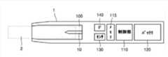
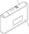
図1は、一実施形態によるエアロゾル生成装置及びシガレットの使用について説明するための図面である。 FIG. 1 is a drawing for explaining the use of an aerosol generator and a cigarette according to one embodiment.
図1を参照すれば、エアロゾル生成装置1は、細長型(elongate)棒の外形を有するホルダにも作製される。ユーザは、エアロゾル生成装置1を、既存の一般シガレットのように、指の間に挟んで使用することができる。 With reference to FIG. 1, the
エアロゾル生成装置1は、バッテリによって供給された電力によって電気的に加熱されるヒータ10を内部に具備する。ヒータ10は、エアロゾル生成装置1の一末端に形成された空スペース(または、キャビティ)100内に位置するように固定されている。シガレット3は、エアロゾル生成装置1の空スペース100内に収容可能であり、収容された場合、ヒータ10は、シガレット3の一末端に設けられたエアロゾル生成物質21の内部を貫通することができる。一方、シガレット3は、タバコ、煙草、ヒートスティック(heatstick)のような多様な用語でも使用される。シガレット3は、一端には、エアロゾル生成物質21がパッケージングされ、他端には、フィルタ22が具備された喫煙用物品であり、エアロゾル生成物質21とフィルタ22は、互いに当接するようにラッパで覆い包まれている。 The
シガレット3がエアロゾル生成装置1内の空スペース100に挿入されれば、エアロゾル生成装置1は、ヒータ10を加熱する。シガレット3内のエアロゾル生成物質21は、加熱されたヒータ10によって温度が上昇し、それにより、エアロゾルが生成される。生成されたエアロゾルは、シガレット3のフィルタ22を介して、ユーザに伝達される。ここで、ヒータ10は、エアロゾル生成物質21が燃焼されない温度であり、エアロゾル生成物質21を加熱する。 When the
ヒータ10は、バッテリから供給された電力によって電気的に加熱される。図1に図示されたヒータ10は、エアロゾル生成物質21に挿入される一末端が鋭角に仕上げられた、1つの縫針(needle)形態でもある。しかし、それに制限されず、ヒータ10は、管形ヒータ、複数本の縫針ヒータなど多様な形態にも具現され、ヒータ10の一末端は、尖った形態の代わりに、湾曲な他の形態などにも具現される。すなわち、ヒータ10は、シガレット3のエアロゾル生成物質21を、エアロゾルが発生する燃焼温度以下に加熱することができる限り、その形態は、制限なしにも採用される。 The
図2は、一実施形態によるエアロゾル生成装置のハードウェア構成を図示したブロック図である。 FIG. 2 is a block diagram illustrating the hardware configuration of the aerosol generator according to one embodiment.
図2を参照すれば、エアロゾル生成装置1は、ヒータ10、制御部120、メモリ115、バッテリ110、センサ130及びインターフェース140を含んでもよい。ただし、エアロゾル生成装置1は、図2に図示された構成要素以外に、他の汎用的な構成要素がさらに含まれて具現されるか、あるいは図2に図示された構成要素のうち一部が省略されて具現されるというあることは、本実施形態と係わる技術分野において当業者ならであるならば、理解することができるであろう。 Referring to FIG. 2, the
ヒータ10は、制御部120の制御により、バッテリ110から供給された電力によって電気的に加熱される。ヒータ10は、電気抵抗性ヒータでもある。例えば、ヒータ10は、電気伝導性トラックを含み、該電気伝導性トラックに電流が流れることにより、ヒータ10が加熱される。ヒータ10に電力が供給される場合、ヒータ10の表面温度は、400℃以上に上昇する。ヒータ10に電力が供給され始めたときから一定時間(例えば、15秒)過ぎる前、ヒータ10の表面温度は、約350℃まで上昇する。
制御部120は、エアロゾル生成装置1の全般的な動作を制御するハードウェアである。制御部120は、マイクロプロセッサ、マイクロコントローラのようなプロセッシングユニットによって具現された集積回路である。 The
制御部120は、センサ130によってセンシングされた結果を分析し、続いて遂行される処理を制御する。制御部120は、センシング結果により、バッテリ110からヒータ10への電力供給を開始または中断させることができる。また、制御部120は、ヒータ10が所定温度まで加熱されるか、あるいは適切な温度を維持するように、ヒータ10に供給される電力の量、及び電力が供給される時間を制御することができる。さらに、制御部120は、インターフェース140の多様な入力情報及び出力情報を処理することができる。 The
制御部120は、エアロゾル生成装置1を利用したユーザの喫煙回数を計数し、計数結果により、ユーザの喫煙を制限するように、エアロゾル生成装置1の関連機能を制御することができる。それについては、以下、当該図面において、さらに詳細に説明する。 The
メモリ115は、喫煙時刻、喫煙回数のようなユーザの喫煙パターンについてのデータを保存することができる。メモリ115は、エアロゾル生成装置1内で処理される各種データを保存するハードウェアであり、メモリ115は、制御部120で処理されたデータ、及び処理されるデータを保存することができる。メモリ115は、DRAM(dynamic random access memory)・SRAM(static random access memory)のようなRAM(random access memory)、ROM(read-only memory)、EEPROM(electrically erasable programmable read-only memory)のような多種にも具現される。 The
バッテリ110は、エアロゾル生成装置1が動作するのに利用される電力を供給する。すなわち、バッテリ110は、ヒータ10が加熱されるように、電力を供給することができる。また、バッテリ110は、エアロゾル生成装置1内に具備された他のハードウェア、制御部120、センサ130及びインターフェース140の動作に必要な電力を供給することができる。バッテリ110は、リチウムリン酸鉄(LiFePO4)バッテリでもあるが、それに制限されず、酸化リチウムコバルト(LiCoO2)バッテリ、リチウムチタン酸塩バッテリなどにも作製される。バッテリ110は、充電が可能なバッテリでもあり、1回使用バッテリでもある。The
センサ130は、パフ感知(puff detect)センサ(温度感知センサ、流量感知センサなど)、シガレット感知センサのような多種のセンサを含んでもよい。該パフ感知センサは、圧力センサなどによっても具現される。シガレット感知センサは、静電容量型センサまたは抵抗センサによっても具現される。センサ130によってセンシングされた結果は、制御部120に伝達され、制御部120は、センシング結果により、ヒータ温度の制御、喫煙の制限、お知らせ表示のような多様な機能が遂行されるように、エアロゾル生成装置1を制御することができる。 The
インターフェース140は、時刻情報を出力するディスプレイまたはランプ、触覚情報を出力するモータ、音情報を出力するスピーカ、ユーザから入力された情報を受信したり、ユーザに情報を出力したりする入出力(I/O)インタフェーシング手段(例えば、ボタンまたはタッチスクリーン)、クレードル(または、クレードルデバイスとも言う)とデータ通信を行ったり、クレードルから充電電力を供給されたりするための端子、外部デバイスと無線通信(例えば、WI-FI、WI-FI Direct、Bluetooth、NFC(near field communication)など)を行うための通信インタフェーシングモジュールのような多様なインタフェーシング手段を含んでもよい。ただし、エアロゾル生成装置1は、以上で例示の多様なインタフェーシング手段のうち一部のみを取捨選択しても具現される。 The
図3Aは、一実施形態による、ホルダ形態に作製されたエアロゾル生成装置を図示した図面である。 FIG. 3A is a diagram illustrating an aerosol generating device fabricated into a holder, according to one embodiment.
図3Aを参照すれば、エアロゾル生成装置1においてヒータ10は、1本の縫針形態にも具現される。縫針型ヒータ10は、シガレット3内部に挿入された状態で、シガレット3のエアロゾル生成物質を加熱し、エアロゾルを発生させることができる。しかし、それに制限されるものではなく、ヒータ10は、エアロゾル生成物質の内部または外部を加熱することができる他の多様な形態にも具現される。 Referring to FIG. 3A, in the
エアロゾル生成装置1のハウジング内には、図2で説明されたヒータ10、制御部120、メモリ115、バッテリ110、センサ130及びインターフェース140が含まれてもよい。エアロゾル生成装置1内の各ハードウェアの機能及び動作は、図2で説明したところに対応する。 The housing of the
図3Bは、他の実施形態による、ホルダ形態に作製されたエアロゾル生成装置を図示した図面である。 FIG. 3B is a diagram illustrating an aerosol generating device fabricated in the form of a holder, according to another embodiment.
図3Bを参照すれば、図3Aと比較し、エアロゾル生成装置1は、液状保存部300をさらに含んでもよい。液状保存部300には、液体エアロゾル生成物質が含まれている。図3Bのエアロゾル生成装置1は、シガレット3の固体エアロゾル生成物質と、液状保存部300の液体エアロゾル生成物質とを同時、または相互に加熱することにより、エアロゾル生成物質を生成することができる。図3Bのエアロゾル生成装置1は、液体エアロゾル生成物質を別途のヒータを介して加熱することもでき、液体エアロゾル生成物質と固体エアロゾル生成物質とを加熱するヒータの具現は、制限なしに採用される。一方、ユーザは、シガレット3のフィルタを介して、エアロゾルを吸入するので、液状保存部300の液体エアロゾル生成物質から生成されたエアロゾルが、シガレット3のフィルタに流入される通路が、エアロゾル生成装置1内に設けられる。 3B, compared with FIG. 3A, the
以下、図面においては、図2、図3Aまたは図3Bに図示されたハードウェア構成を有するエアロゾル生成装置1を連繋させ、本実施形態について詳細に説明する。 Hereinafter, in the drawings, the
図4は、一実施形態による、エアロゾル生成装置を利用したユーザの喫煙パターンを図示した図面である。 FIG. 4 is a diagram illustrating smoking patterns of a user using an aerosol generating device, according to one embodiment.
図4を参照すれば、1週間の間、あるユーザがエアロゾル生成装置1を利用しながら、曜日ごとに、喫煙時刻と喫煙回数とに対するモニタリング結果を示した表400が図示されている。表400は、本実施形態の説明の便宜のために、任意に図示されたものであるので、本実施形態は、それに制限されるものではない。 Referring to FIG. 4, a table 400 showing monitoring results of smoking time and number of times of smoking for each day of the week while a certain user uses the
エアロゾル生成装置1のセンサ130は、シガレット3の挿入及び抽出をセンシングしたり、ヒータ温度の変化をセンシングしたりするものであり、喫煙の開始と終了とをセンシングすることができる。それにより、制御部120は、センシング結果に基づいて、1回の喫煙が完了した時刻を判断しながら、1回の喫煙が完了したことを計数することができる。また、制御部120は、インターフェース140のボタン入力によるエアロゾル生成装置1の電源オン/電源オフ信号に基づいて、喫煙時刻のチェック、及び喫煙回数の計数を行うことができる。メモリ115は、喫煙時刻及び喫煙回数に係わる累積情報を保存することができる。ただし、エアロゾル生成装置1が、1回喫煙を判断する方式及び基準は、それ以外にも多様に採用される。 The
図4の例示において、ユーザは、エアロゾル生成装置1を利用し、AM06:00から翌日AM06:00まで1日間に、10回だけ喫煙が可能になるように、エアロゾル生成装置1での喫煙制限機能を設定したと仮定する。ただし、該喫煙制限条件の設定は、多様である。例えば、前述の例示と異なり、任意の期間の間、総任意回数まで喫煙するようにも設定され、該期間の起算時点は、任意時刻にも設定される。また、過度に短い間隔で喫煙することを制限するために、以前喫煙終了後、任意期間以内の喫煙に対しては、制限されるようにも設定される。 In the example of FIG. 4, the user uses the
表400を参照すれば、ユーザは、月曜日に、総9回喫煙を試みたので、エアロゾル生成装置1の喫煙制限機能は、活性化されていない。ユーザは、火曜日に、総10回喫煙を行い、10回目喫煙後、11回目及び12回目の喫煙はエアロゾル生成装置1の喫煙制限機能によって正常に遂行されなかった。ユーザは、水曜日には、総10回喫煙を行い、このとき、8回目喫煙と10回目喫煙との間の2回の喫煙試みは、喫煙制限機能によって制限され、11回目喫煙も制限された。このように、エアロゾル生成装置1の制御部120は、ユーザの喫煙回数を累積して計数し、設定された喫煙制限条件が充足された場合、エアロゾル生成装置1の喫煙制限機能を活性化することにより、ユーザの喫煙が制限される。 Referring to table 400, the user attempted to smoke a total of nine times on Monday, so the smoking restriction function of
表400に図示された木曜日から土曜日までの喫煙パターンによれば、火曜日及び水曜日の喫煙パターンと類似し、設定された喫煙制限条件が充足された場合、エアロゾル生成装置1の喫煙制限機能によって喫煙が制限された。 According to the smoking pattern from Thursday to Saturday illustrated in the table 400, it is similar to the smoking pattern on Tuesday and Wednesday, and if the set smoking restriction condition is satisfied, the smoking restriction function of the
エアロゾル生成装置1の制御部120は、あらかじめ設定された臨界期間の間、ユーザの喫煙回数があらかじめ設定された臨界回数に逹したか否かということに基づいて、喫煙制限条件を充足するか否かということを判断することができる。 The
さらに、エアロゾル生成装置1は、設定された喫煙制限回数を超えた後の喫煙試みに対して制限するだけではなく、設定された喫煙制限間隔内の隣接した喫煙試みに対しても、制限することができる。ただし、前述のように、エアロゾル生成装置1で適用される喫煙制限条件は、多様に設定される、多様な条件下で喫煙が制限される。 Furthermore, the
図5は、一実施形態による、ヒータ温度の変化により、喫煙の開始と終了とを判断することについて説明するための図面である。 FIG. 5 is a diagram for explaining the determination of the start and end of smoking based on changes in heater temperature, according to an embodiment.
図5を参照すれば、センサ130は、ユーザのパフによるヒータ温度の変化をセンシングする温度感知センサを含むようにも具現される。ユーザのパフ時、エアロゾル生成装置1には、ヒータ温度より低い温度の空気が流入されるので、ユーザがエアロゾルを吸入する時点(500)においては、ヒータ10の温度がわずかに低くなる。このとき、エアロゾル生成装置1は、喫煙間には、ヒータ10に電力を供給しているので、ヒータ温度が再び一定温度に維持される。従って、エアロゾル生成装置1の制御部120は、喫煙が始まった後、センサ130によってセンシングされたヒータ温度をモニタリングしながら、ヒータ温度がわずかに低くなる時点(500)にパフが発生したと判断することができる。 Referring to FIG. 5, the
1回の喫煙は、ユーザがシガレット3を複数回パフィング(puffing)したとき、完了したと計数される。例えば、1回の喫煙は、ユーザがエアロゾル生成装置1に挿入されたシガレット3を約14回パフィングすることで完了したと判断される。すなわち、一実施形態によれば、エアロゾル生成装置1の制御部120は、ヒータ温度の変化に対応するパフ回数を基準に、喫煙の開始と終了とを判断することができ、あらかじめ設定されたパフの臨界回数ほどユーザがシガレット3をパフィングした場合、1回の喫煙が終わったと判断し、喫煙回数を計数することができる。 A puff is counted as completed when the user puffs the
一方、他の実施形態によれば、エアロゾル生成装置1は、ヒータ温度以外にも、他の基準を利用し、喫煙の開始と終了とを判断し、喫煙回数を計数することができる。 On the other hand, according to other embodiments, the
例えば、エアロゾル生成装置1のセンサ130は、シガレット感知センサを含むようにも具現される。制御部120は、シガレット感知センサにより、シガレット3が挿入されたことがセンシングされるときには、喫煙が始まったと判断し、その後、シガレット3が抽出されたことがセンシングされるときには、喫煙が終わったと判断することができる。すなわち、エアロゾル生成装置1は、1回の喫煙をシガレット3の挿入及び抽出に対するセンシング結果に基づいて、計数することができる。 For example, the
一方、エアロゾル生成装置1のセンサ130は、流量感知センサを含むようにも具現される。ユーザのパフ時、エアロゾル生成装置1の外部から空気が流入され、エアロゾル生成装置1内の流量が増大するようになるので、エアロゾル生成装置1内において、流量は、ユーザのパフごとに変化する。従って、エアロゾル生成装置1の制御部120は、流量の変化に対応するパフ回数を基準に、喫煙の開始と終了とを判断することができ、あらかじめ設定されたパフの臨界回数ほどユーザがシガレット3をパフィングした場合、1回の喫煙が終わったと判断し、喫煙回数を計数することができる。 Meanwhile, the
それ以外にも、エアロゾル生成装置1は、インターフェース140を介したボタン入力を基準に、喫煙回数を計数することもできる。 In addition, the
結局、エアロゾル生成装置1のコントローラは、インターフェース140を介したボタン入力、シガレット挿入及び抽出のセンシング、ヒータ温度変化によるパフのセンシング、流量変化によるパフのセンシングのような多様な方式で、喫煙の開始と終了とを判断することにより、喫煙回数を計数することができる。 As a result, the controller of the
エアロゾル生成装置1は、前述の方式による喫煙回数の計数結果、及び喫煙が完了した時点についての情報を、図4の表400のようにモニタリングしながら、喫煙制限条件が充足された場合には、喫煙制限機能を活性化させ、ユーザの喫煙を制限することができる。 The
図6は、一実施形態によるエアロゾル生成装置の喫煙制限機能について説明するための図面である。 FIG. 6 is a drawing for explaining the smoking restriction function of the aerosol generating device according to one embodiment.
図6を参照すれば、喫煙モードでのヒータ温度の変化グラフ601、及び喫煙制限モードでのヒータ温度の変化グラフ602が図示されている。該喫煙モードは、エアロゾル生成装置1の喫煙制限機能が非活性化された状態であり、ユーザがエアロゾル生成装置1に挿入されたシガレット3で、正常に喫煙を行うことができるモードを意味する。該喫煙制限モードは、エアロゾル生成装置1の喫煙制限機能が活性化された状態であり、ユーザがエアロゾル生成装置1の電源をオンにし、エアロゾル生成装置1にシガレット3を挿入しても、喫煙モードと異なり、正常な喫煙が制限されるモードを意味する。該喫煙制限モードは、ユーザの喫煙回数が喫煙制限条件を充足された場合、活性化される。 Referring to FIG. 6, a heater temperature change graph 601 in the smoking mode and a heater temperature change graph 602 in the smoking restriction mode are shown. The smoking mode is a state in which the smoking restriction function of the
喫煙制限条件が充足されるか否かということにより、制御部120の制御により、ヒータ10は、エアロゾルを生成するための電力をバッテリから供給されるか、あるいはヒータ10は、電力の供給が制限される。エアロゾル生成装置1は、喫煙制限モードで多様な喫煙制限機能を行うことができる。 Depending on whether or not the smoking restriction condition is satisfied, the
喫煙制限機能の一例として、図6のグラフ602に図示されているように、喫煙制限モードにおいて制御部120は、ヒータ10の温度を喫煙モードで制御される温度範囲より低く制御することができる。言い換えれば、喫煙制限条件が充足された喫煙制限モードである場合、制御部120は、喫煙制限条件が充足されていない喫煙モード下で制御されるヒータ10の温度範囲に比べ、低い温度範囲でヒータ10が制御されるように、ヒータ10への電力供給を制限することができる。それにより、エアロゾル生成装置1においては、比較的少量のエアロゾルだけが生成される。すなわち、低い温度範囲の意味は、喫煙制限モード下において、ヒータ10の加熱によって生成されるエアロゾルの量が、喫煙モード下において、ヒータ10の加熱によって生成されるエアロゾルの量より少なくなるための温度範囲に該当する。従って、ユーザは、シガレット3をパフィングしても、ユーザは、少量のエアロゾルしか吸入することができないので、ユーザは、喫煙モードに比べ、顕著に低下された喫煙感を感じてしまい、それにより、ユーザの喫煙が制限されるのである。 As an example of the smoking restriction function, in the smoking restriction mode, the
一方、喫煙制限モードにおいて、低く制御される温度範囲は、ヒータ10の予熱後、エアロゾルを生成させるために、一定範囲内の温度に維持される区間510で制御される温度範囲を意味する。しかし、それに制限されるものではなく、ヒータ10の予熱から冷却までの全区間の間で変化される温度範囲をも意味し、そのうち、多様な一部区間の温度範囲をも意味する。低く制御される温度値は、エアロゾル生成装置1での設定によって多様にも変更される。 On the other hand, in the smoking restriction mode, the temperature range controlled to be low means the temperature range controlled in section 510, which is maintained within a certain range in order to generate an aerosol after preheating the
喫煙制限機能の他の例として、喫煙制限モードにおいて制御部120は、エアロゾル生成装置1にシガレット3が挿入されても、ヒータ10の温度が全く上昇しないようにヒータ10を非活性化させることができる。従って、エアロゾル生成装置1においては、エアロゾルが全く生成されないために、ユーザは、喫煙感を感じることができず、それにより、ユーザの喫煙が制限されるのである。 As another example of the smoking restriction function, in the smoking restriction mode, the
図7は、一実施形態による、喫煙制限モードにおいて、エアロゾル生成装置のインタフェーシング方式について説明するための図面である。 FIG. 7 is a diagram illustrating an interfacing scheme of an aerosol generator in a smoking restriction mode, according to one embodiment.
図7を参照すれば、ユーザは、インターフェース140のボタン141をクリックすることにより、エアロゾル生成装置1の電源をオンにし、エアロゾル生成装置1に喫煙開始を要請することができる。このとき、エアロゾル生成装置1は、インターフェース140を介して、多様な方式で、現在喫煙制限機能が活性化されていることをユーザに知らせることができる。 Referring to FIG. 7, the user can turn on the
1番方式701によれば、エアロゾル生成装置1のインターフェース140がディスプレイ143を含むように具現された場合、ディスプレイ143は、現在は、喫煙制限モードにより、エアロゾル生成装置1は、喫煙制限機能が活性化されていることをユーザに知らせるシンボルを表示することができる。 According to
2番方式702によれば、エアロゾル生成装置1のインターフェース140が、ランプ(例えば、LEDランプ)を含むように具現された場合、該ランプは、カラーが変わったり、ちらついたりすることを介して、現在エアロゾル生成装置1は、喫煙制限モードにより、喫煙制限機能が活性化されていることをユーザに知らせることができる。 According to
3番方式703によれば、エアロゾル生成装置1のインターフェース140がスピーカを含むように具現された場合、該スピーカは、サウンドを出力することにより、現在エアロゾル生成装置1は、喫煙制限モードにより、喫煙制限機能が活性化されていることをユーザに知らせることができる。 According to
4番方式704によれば、エアロゾル生成装置1のインターフェース140がモータを含むように具現された場合、該モータは、振動を起こすことにより、現在エアロゾル生成装置1は、喫煙制限モードにより、喫煙制限機能が活性化されていることをユーザに知らせることができる。 According to method No. 4 704, if the
インターフェース140は、喫煙制限条件が充足された喫煙制限モードである場合、ディスプレイ143、ランプ、スピーカ、モータ振動のようなインタフェーシング手段を利用し、喫煙制限モードが活性化されたことを示すお知らせを提供する。それ以外にも、エアロゾル生成装置1は、インターフェース140に含まれた他種のハードウェア構成により、多様な方式で喫煙制限モードのお知らせをユーザに提供することができる。 The
図8は、一実施形態による、喫煙回数についての情報、及び喫煙制限モードについての情報を、インターフェースを介して表示することについて説明するための図面である。 FIG. 8 is a diagram illustrating displaying information about the number of smoking times and information about a restricted smoking mode via an interface, according to an embodiment.
図8を参照すれば、エアロゾル生成装置1にディスプレイ143が具備された場合、ユーザがエアロゾル生成装置1にシガレット3を挿入して喫煙を完了した場合、累積された喫煙回数がディスプレイ143を介して表示される。喫煙制限条件が1日10回であると設定された場合、22:00時近辺の2回の喫煙試みに対して、ディスプレイ143は、喫煙制限モードにより、喫煙制限機能が活性化されていることを示すシンボルを表示することができる。 Referring to FIG. 8 , when the
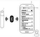
図9は、他の実施形態による、喫煙回数についての情報、及び喫煙制限モードについての情報をインターフェースを介して表示することについて説明するための図面である。 FIG. 9 is a diagram illustrating displaying information about the number of times of smoking and information about a smoking restriction mode through an interface according to another embodiment.
図9を参照すれば、エアロゾル生成装置1のインターフェース140は、外部デバイス900と、無線通信(例えば、Bluetooth)を行うための通信インターフェースモジュールを含むようにも具現される。インターフェース140は、制御部120によって判断された喫煙回数についての情報、及び喫煙制限モードについての情報を、無線通信を介して、外部デバイス900に伝送することができる。それにより、外部デバイス900は、ポップアップ窓910を介して受信された情報を示すプッシュメッセージを提供することができる。従って、ユーザは、エアロゾル生成装置1にディスプレイ143が具備されなかったとしても、外部デバイス900で表示されたポップアップ窓910を介して、喫煙回数についての情報、及び喫煙制限モードについての情報を確認することができる。 Referring to FIG. 9, the
図10は、一実施形態による、エアロゾル生成装置において、喫煙制限条件を設定することについて説明するための図面である。 FIG. 10 is a diagram for explaining setting of smoking restriction conditions in the aerosol generating device according to one embodiment.
図10を参照すれば、エアロゾル生成装置1のインターフェース140は、ボタン141及びディスプレイ143を含むようにも具現される。または、図10には、図示されていないが、インターフェース140は、タッチスクリーンを含むようにも具現される。 Referring to FIG. 10, the
喫煙制限条件の項目には、臨界回数(threshold number)、臨界期間(threshold period)などが含まれてもよい。一例により、ディスプレイ143は、臨界回数、臨界期間などを、スクロールを介して設定することができる画面1000を表示し、ユーザは、ボタン141入力により、画面1000をスクロールすることにより、所望の臨界回数、臨界期間などの喫煙制限条件を設定することができる。 Items of smoking restriction conditions may include a threshold number, a threshold period, and the like. For example, the
図11は、他の実施形態による、エアロゾル生成装置の喫煙制限条件を設定することについて説明するための図面である。 FIG. 11 is a diagram for explaining setting a smoking restriction condition of an aerosol generating device according to another embodiment.
図11を参照すれば、エアロゾル生成装置1のインターフェース140は、外部デバイス900と、無線通信(例えば、Bluetooth)を行うための通信インターフェースモジュールを含むようにも具現される。エアロゾル生成装置1と外部デバイス900とが連結された場合、外部デバイス900においては、電子タバコアプリケーション1110が実行される。ユーザは、電子タバコアプリケーション1100を利用し、喫煙制限条件、アラーム方式、ヒータ温度のような多様な項目を設定することができる。 Referring to FIG. 11, the
まず、電子タバコアプリケーション1100を介して、エアロゾル生成装置1で喫煙制限モードを使用するか否かということが設定される。もし喫煙制限モードを使用しない場合、エアロゾル生成装置1は、喫煙回数と関係なく喫煙を行うことができる。 First, it is set via the electronic cigarette application 1100 whether or not the
喫煙制限条件のうち一つとして、臨界期間が設定される。該臨界期間は、喫煙回数を制限する期間を意味する。該臨界期間は1日、1週間、1ヵ月を基準に設定されるか、あるいは特定曜日、特定時間帯など多様な期間別にも設定される。さらに、該臨界期間は、期間の起算点が設定されもする。 A critical period is set as one of the smoking restriction conditions. The critical period refers to the period during which smoking times are limited. The critical period is set based on one day, one week, one month, or set for various periods such as a specific day of the week and a specific time period. Further, the critical period is also set with a starting point of the period.
該喫煙制限条件のうち他の一つとして、臨界回数が設定される。設定された臨界期間内、設定された臨界回数ほど喫煙した場合、その後の喫煙は、制限される。該臨界回数は、総喫煙回数に対して設定されるか、あるいは総パフ回数に対しても設定される。前述のように、1回の喫煙は、ユーザがシガレット3を複数回パフィング(例えば、14回)したとき、完了したと計数される。 A critical number of times is set as another one of the smoking restriction conditions. If a person smokes a set critical number of times within a set critical period, then smoking is restricted. The critical number is set for the total number of smokes or even for the total number of puffs. As previously mentioned, a puff is counted as complete when the user puffs the
喫煙制限条件のうちさらに他の一つとして、連続喫煙制限期間が設定される。エアロゾル生成装置1は、ヒータ10を電気的に加熱する方式であるので、短時間内に連続的な喫煙が試みられる場合には、ヒータ10及びエアロゾル生成装置1の寿命を短くする。すなわち、喫煙のためのヒータ10の加熱後には、望ましい冷却時間が要求される。一方、短時間内の連続的な喫煙は、ユーザの健康にも有害である。従って、喫煙制限条件と設定された連続喫煙制限期間内には、ユーザの喫煙が制限される。前述の図4を参照すれば、ユーザは、水曜日に、8回目喫煙と10回目喫煙との間に喫煙が制限されたが、それは、連続喫煙制限期間が設定されたからである。 A continuous smoking restriction period is set as another one of the smoking restriction conditions. Since the
電子タバコアプリケーション1100を介して、喫煙制限モードの活性化を知らせる方式が設定される。例えば、図7で説明された方式のうち少なくとも一つが設定される。 Via the e-cigarette application 1100, a scheme is set to signal the activation of the restricted smoking mode. For example, at least one of the methods described with reference to FIG. 7 is set.
喫煙制限モードが活性化された場合、図6においては、喫煙を制限する方式のうち1つの例として、ヒータ温度を低くする方式について説明された。電子タバコアプリケーション1100を介して、喫煙制限モードで制限されるヒータ温度の範囲も設定される。 When the smoking restriction mode is activated, in FIG. 6, the method of lowering the heater temperature has been described as one example of the method of restricting smoking. Via the e-cigarette application 1100, the range of heater temperatures that are restricted in the restricted smoking mode is also set.
一方、図11においては、電子タバコアプリケーション1110において設定可能な多様な項目について説明されたが、それらは、本実施形態の説明の便宜のための例示に過ぎず、電子タバコアプリケーション1110は、図11で説明された項目のうち一部項目のみを提供するか、あるいは他の汎用的な項目を追加して提供することもできる。 On the other hand, although various items that can be set in the
外部デバイス900で実行された電子タバコアプリケーション1110を介して、多様な設定が完了した場合、外部デバイス900は、無線通信を介して、電子タバコアプリケーション1110で入力された設定情報を、エアロゾル生成装置1に伝送することができる。その後、エアロゾル生成装置1は、受信された設定情報によって動作される。 When various settings are completed via the
図12は、さらに他の実施形態による、エアロゾル生成装置の喫煙制限条件を設定することについて説明するための図面である。 FIG. 12 is a diagram for explaining setting smoking restriction conditions of an aerosol generating device according to still another embodiment.
図12を参照すれば、エアロゾル生成装置1は、クレードル2にも結合される。クレードル2は、エアロゾル生成装置1に充電電力を提供する装置でもある。エアロゾル生成装置1とクレードル2は、端子が互いに当接しながら接触される。エアロゾル生成装置1の端子は、例えば、マイクロピンによって具現され、インターフェース140に含まれる。エアロゾル生成装置1の一部端子は、通信用端子と充電用端子とを含んでもよい。 With reference to FIG. 12, the
クレードル2は、外部デバイス1200と、ケーブルを介して有線連結される。エアロゾル生成装置1がクレードル2に結合された状態で、外部デバイス1200と有線連結された場合、ユーザは、外部デバイス1200で、電子タバコアプリケーション1210を実行させ、エアロゾル生成装置1に対する設定を入力することができる。ここで、エアロゾル生成装置1に対する設定は、先に図11で説明された多様な設定を含んでもよい。
外部デバイス1200で実行された電子タバコアプリケーション1210を介して、多様な設定が完了された場合、外部デバイス1200は、有線通信を介して、電子タバコアプリケーション1210で入力された設定情報を、クレードル2に伝送することができる。クレードル2は、エアロゾル生成装置1と接触された通信用端子を介して、設定情報をエアロゾル生成装置1に伝送し、エアロゾル生成装置1は、受信された設定情報によって動作される。 When various settings are completed through the
結局、該喫煙制限条件は、インターフェース140を介して入力された設定情報、外部デバイス900から無線通信によって受信された設定情報、クレードル2に結合された状態で、外部デバイス1200から有線通信によって受信された設定情報などに基づいたものでもある。 Ultimately, the smoking restriction conditions include setting information input via
ただし、たとえ図12に図示されていないにしても、クレードル2は、外部デバイス1200と有線通信ではない、無線通信(例えば、WI-FI、WI-FI Direct、Bluetooth、NFCなど)も可能である。すなわち、クレードル2にエアロゾル生成装置1が挿入された状態で、外部デバイス1200は、クレードル2と無線通信が可能であり、外部デバイス1200においては、電子タバコアプリケーション1210を介して設定情報の設定が可能であり、外部デバイス1200は、クレードル2に設定情報の伝送が可能である。クレードル2が無線受信した設定情報は、結局、エアロゾル生成装置1の設定としても適用される。 However, even though not shown in FIG. 12, the
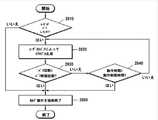
図13は、一実施形態によるエアロゾル生成装置において、喫煙制限機能を提供する方法の詳細フローチャートである。 FIG. 13 is a detailed flowchart of a method of providing smoking restriction functionality in an aerosol generating device according to one embodiment.
図13を参照すれば、喫煙制限機能の提供方法は、前述の図面のエアロゾル生成装置1において、時系列的に処理される段階によって構成される。従って、以下で省略された内容であるとしても、前述の図面のエアロゾル生成装置1について記述された内容であるならば、図13の方法にも適用されるのである。 Referring to FIG. 13, the method for providing the smoking restriction function is configured by the steps processed in chronological order in the
1301段階において、エアロゾル生成装置1は、ユーザから喫煙開始要請を受信する。喫煙開始要請の有無は、制御部120が、エアロゾル生成装置1のインターフェース140を介した入力が存在するか否かということを判断するか、あるいはセンサ130によるシガレット挿入の感知、ヒータ温度の変化などのセンシング結果に基づいて、判断することができる。 At
1302段階において、制御部120は、メモリ115に保存された喫煙パターンについてのデータに基づき、喫煙開始要請が、喫煙を制限するための喫煙制限条件を充足するか否かということを判断する。具体的には、制御部120は、現在まで計数された喫煙回数が、臨界回数に逹したか否かということを判断する。もし計数された喫煙回数が臨界回数に逹したと判断されれば、制御部120は、喫煙制限モードを活性化させ、1303段階を遂行する。しかし、喫煙回数が臨界回数に達していないと判断されれば、制御部120は、喫煙モードにより、1307段階を遂行する。 In
1303段階において、制御部120は、喫煙制限モードで、ヒータ10を非活性化させるか否かということを判断する。 In
1304段階において、制御部120は、喫煙モードで制御されるヒータ10の温度範囲より低いように、ヒータ10の温度を制御することにより、ユーザの喫煙を制限する。 In
1305段階において、制御部120は、ヒータ10を非活性化させ、ユーザの喫煙を制限する。 At
1306段階において、インターフェース140は、ディスプレイ、ランプ、スピーカ、モータの振動などを介して、喫煙制限機能が活性化されていることをユーザに知らせる。 At
1307段階において、制御部120は、喫煙モードにより、エアロゾルが正常に生成される温度にヒータ10を制御する。 In
図14は、一実施形態によるエアロゾル生成装置において、喫煙制限機能を提供する方法のフローチャートである。 FIG. 14 is a flowchart of a method of providing smoking restriction features in an aerosol generating device according to one embodiment.
図14を参照すれば、喫煙制限機能の提供方法は、前述の図面のエアロゾル生成装置1において、時系列的に処理される段階によって構成される。従って、以下で省略された内容であるとしても、前述の図面のエアロゾル生成装置1について記述された内容は、図14の方法にも適用される。 Referring to FIG. 14, the method of providing the smoking restriction function is configured by the steps processed in chronological order in the
1401段階において、制御部120は、ユーザの喫煙パターンをモニタリングする。該モニタリング結果は、メモリ115に保存される。 At
1402段階において、インターフェース140は、ユーザから喫煙開始のための要請を受信する。 At
1403段階において、制御部120は、喫煙パターンに対するモニタリングに基づき、受信された要請が喫煙を制限するための喫煙制限条件を充足するか否かということを判断する。 In
1404段階において、制御部120は、喫煙制限条件が充足されるか否かということにより、エアロゾルを生成するための電力が、バッテリからヒータ10に供給されるか、あるいは電力の供給が制限されるようにヒータ10を制御する。 In
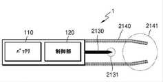
図15は、エアロゾル生成装置の一例を図示した構成図である。 FIG. 15 is a configuration diagram illustrating an example of an aerosol generator.
図15を参照すれば、エアロゾル生成装置1(以下、ホルダとする)は、バッテリ110、制御部120及びヒータ2130を含む。また、ホルダ1は、ケース2140によって形成された内部空間を含む。ホルダ1の内部空間には、シガレットが挿入される。 Referring to FIG. 15, the aerosol generator 1 (hereinafter referred to as holder) includes a
図15に図示されたホルダ1には、本実施形態と係わる構成要素だけが図示されている。従って、図15に図示された構成要素以外に、他の汎用的な構成要素がホルダ1にさらに含まれてもよいということは、本実施形態と係わる技術分野において当業者であるならば、理解することができるであろう。 In the
シガレットがホルダ1に挿入されれば、ホルダ1は、ヒータ2130を加熱する。シガレット内のエアロゾル生成物質は、加熱されたヒータ2130によって温度が上昇し、それにより、エアロゾルが生成される。生成されたエアロゾルは、シガレットのフィルタを介してユーザに伝達される。ただし、該シガレットがホルダ1に挿入されていない場合にも、ホルダ1は、ヒータ2130を加熱することができる。
ケース2140は、ホルダ1から分離される。例えば、ユーザが、ケース2140を、時計回り方向または反時計回り方向に回すことにより、ケース2140は、ホルダ1から分離される。
また、ケース2140の末端2141が形成する孔の直径は、ケース2140とヒータ2130とによって形成された空間の直径に比べ、小さく作製され、その場合、ホルダ1に挿入されるシガレットのガイド役割を行うことができる。 In addition, the diameter of the hole formed by the
バッテリ110は、ホルダ1が動作するのに利用される電力を供給する。例えば、バッテリ110は、ヒータ2130が加熱されるように電力を供給することができ、制御部120が動作するのに必要な電力を供給することができる。また、バッテリ110は、ホルダ1に設けられたディスプレイ、センサ、モータなどが動作するのに必要な電力を供給することができる。 A
バッテリ110は、リチウムリン酸鉄(LiFePO4)バッテリでもあるが、前述の例に限定されるものではない。例えば、バッテリ110は、酸化リチウムコバルト(LiCoO2)バッテリ、リチウムチタン酸塩バッテリなどが該当する。
また、バッテリ110は、直径が10mmであり、長さが37mmである円柱状でもあるが、それに限定されるものではない。バッテリ110の容量は、120mAh以上でもあり、充電が可能なバッテリであるか、あるいは1回使用バッテリでもある。例えば、バッテリ110が充電が可能である場合、バッテリ110の充電率(C-rate)は、10C、放電率(C-rate)は、16Cないし20Cでもあるが、それらに限定されるものではない。また、安定した使用のために、バッテリ110は、充放電が8,000回進められた場合にも、全体容量の80%以上が確保されるように作製される。 Also, the
ここで、バッテリ110の満充電及び完全放電のいかんは、バッテリ110に保存された電力が、バッテリ110の全体容量対比で、どれほどのレベルであるかということによっても判断される。例えば、バッテリ110に保存された電力が、全体容量の95%以上である場合、バッテリ110が満充電されたと判断される。また、バッテリ110に保存された電力が、全体容量の10%以下である場合、バッテリ110が完全放電されたと判断される。しかし、バッテリ110の満充電及び完全放電のいかんに係わる判断基準は、前述の例に限定されるものではない。 Here, whether the
ヒータ2130は、バッテリ110から供給された電力によって加熱される。シガレットがホルダ1に挿入されれば、ヒータ2130は、該シガレットの内部に位置する。従って、加熱されたヒータ2130は、シガレット内のエアロゾル生成物質の温度を上昇させる。
ヒータ2130は、円柱と円錐とが組み合わされた形状でもある。例えば、ヒータ2130は、直径が約2mm、長さが約23mmである円柱状を有し、ヒータ2130の末端2131は、鋭角に仕上げられるが、それに限定されるものではない。言い換えれば、ヒータ2130は、シガレットの内部に挿入される形態であるならば、制限なしに該当する。また、ヒータ2130は、一部分だけ加熱されもする。例えば、ヒータ2130の長さが23mmであると仮定すれば、ヒータ2130の末端2131から12mmだけ加熱され、ヒータ2130の残り部分は、加熱されない。
ヒータ2130は、電気抵抗性ヒータでもある。例えば、ヒータ2130には、電気伝導性トラック(track)を含み、該電気伝導性トラックに電流が流れることにより、ヒータ2130が加熱される。
安定した使用のために、ヒータ2130には、3.2V、2.4A、8Wの規格による電力が供給されるが、それらに限定されるものではない。例えば、ヒータ2130に電力が供給される場合、ヒータ2130の表面温度は、400℃以上に上昇する。ヒータ2130に電力が供給され始めたときから15秒が超える前、ヒータ2130の表面温度は、約350℃まで上昇する。 For stable use, the
ホルダ1には、別途の温度感知センサが具備される。または、ホルダ1に温度感知センサが具備されず、ヒータ2130が、温度感知センサの役割を行うこともできる。例えば、ヒータ2130には、発熱のための第1電気伝導性トラック以外に、温度感知のための第2電気伝導性トラックがさらに含まれてもよい。 The
例えば、該第2電気伝導性トラックにかかる電圧、及び第2電気伝導性トラックに流れる電流が測定されれば、抵抗(R)が決定される。このとき、下記数式1により、第2電気伝導性トラックの温度(T)が決定される。 For example, if the voltage across the second electrically conductive track and the current flowing in the second electrically conductive track are measured, the resistance (R) is determined. At this time, the temperature (T) of the second electrically conductive track is determined by

数式1で、Rは、第2電気伝導性トラックの現在抵抗値を意味し、R0は、温度T0(例えば、0℃)での抵抗値を意味し、αは、第2電気伝導性トラックの抵抗温度係数を意味する。伝導性物質(例えば、金属)は、固有の抵抗温度係数を有しているが、第2電気伝導性トラックを構成する伝導性物質により、αは、事前に決定されている。従って、第2電気伝導性トラックの抵抗(R)が決定される場合、前記数式1により、第2電気伝導性トラックの温度(T)が演算される。In
ヒータ2130は、少なくとも1つの電気伝導性トラック(第1電気伝導性トラック及び第2電気伝導性トラック)によっても構成される。例えば、ヒータ2130は、2個の第1電気伝導性トラック、及び1個または2個の第2電気伝導性トラックによっても構成されるが、それらに限定されるものではない。
該電気伝導性トラックは、電気抵抗性物質を含む。一例として、該電気伝導性トラックは、金属物質によっても作製される。他の例として、該電気伝導性トラックは、電気伝導性セラミック物質、炭素、金属合金、またはセラミック物質と金属との合成物質によっても作製される。 The electrically conductive track includes an electrically resistive material. As an example, the electrically conductive tracks are also made by a metallic material. As another example, the electrically conductive tracks are also made of electrically conductive ceramic material, carbon, metal alloys, or composites of ceramic materials and metals.
また、ホルダ1は、温度感知センサの役割を行う電気伝導性トラック及び温度感知センサをいずれも含んでもよい。 Also, the
制御部120は、ホルダ1の動作を全般的に制御する。具体的には、制御部120は、バッテリ110及びヒータ2130だけではなく、ホルダ1に含まれた他の構成の動作を制御する。また、制御部120は、ホルダ1の構成それぞれの状態を確認し、ホルダ1が動作可能な状態であるか否かということを判断することもできる。 The
制御部120は、少なくとも1つのプロセッサを含む。該プロセッサは、多数の論理ゲートのアレイによっても具現され、汎用的なマイクロプロセッサと、該マイクロプロセッサで実行されるプログラムが保存されたメモリとの組み合わせによっても具現される。また、他の形態のハードウェアによっても具現されるということは、本実施形態が属する技術分野において当業者であるならば、理解することができるであろう。
例えば、制御部120は、ヒータ2130の動作を制御することができる。制御部120は、ヒータ2130が所定温度まで加熱されるか、あるいは適切な温度を維持するように、ヒータ2130に供給される電力の量、及び電力が供給される時間を制御することができる。また、制御部120は、バッテリ110の状態(例えば、バッテリ110の残量など)を確認し、必要な場合、お知らせ信号を生成することができる。 For example,
また、制御部120は、ユーザのパフの有無、及びパフの強度を確認することができ、パフの数をカウンティングすることができる。また、制御部120は、ホルダ1が作動している時間を続けて確認することができる。また、制御部120は、後述するクレードル2がホルダ1と結合されたか否かということを確認し、クレードル2とホルダ1との結合または分離により、ホルダ1の動作を制御することができる。 In addition, the
一方、ホルダ1は、バッテリ110、制御部120及びヒータ2130以外に、汎用的な構成をさらに含んでもよい。 Meanwhile, the
例えば、ホルダ1は、視覚情報の出力が可能なディスプレイ、または触覚情報の出力のためのモータを含んでもよい。一例として、ホルダ1にディスプレイが含まれる場合、制御部120は、ディスプレイを介して、ユーザにホルダ1の状態に係わる情報(例えば、ホルダの使用可能いかんなど)、ヒータ2130に係わる情報(例えば、予熱開始、予熱進行、予熱完了など)、バッテリ110と係わる情報(例えば、バッテリ110の残余容量、使用可能いかんなど)、ホルダ1のリセットと係わる情報(例えば、リセット時期、リセット進行、リセット完了など)、ホルダ1の掃除と係わる情報(例えば、掃除時期、掃除必要、掃除進行、掃除完了など)、ホルダ1の充電と係わる情報(例えば、充電必要、充電進行、充電完了など)、パフと係わる情報(例えば、パフ回数、パフ終了予告など)、または安全と係わる情報(例えば、使用時間経過など)などを伝達することができる。他の例として、ホルダ1にモータが含まれる場合、制御部120は、モータを利用し、振動信号を生成することにより、ユーザに前述の情報を伝達することができる。 For example, the
また、ホルダ1は、ユーザがホルダ1の機能を制御することができる少なくとも1つの入力装置(例えば、ボタン)、及び/またはクレードル2と結合される端子を含んでもよい。例えば、ユーザは、ホルダ1の入力装置を利用し、多様な機能を行うことができる。ユーザが入力装置を押す回数(例えば、1回、2回など)、または入力装置を押している時間(例えば、0.1秒、0.2秒など)を調節することにより、ホルダ1の複数機能のうち所望機能を実行することができる。ユーザが入力装置を作動させることにより、ホルダ1は、ヒータ2130を予熱する機能、ヒータ2130の温度を調節する機能、シガレットが挿入される空間を掃除する機能、ホルダ1が作動可能な状態であるか否かということを点検する機能、バッテリ110の残量(可用電力)を表示する機能、ホルダ1のリセット機能などが遂行される。しかし、ホルダ1の機能は、前述の例に限定されるものではない。 The
また、ホルダ1は、パフ感知センサ、温度感知センサ及び/またはシガレット挿入感知センサを含んでもよい。例えば、該パフ感知センサは、一般的な圧力センサによっても具現され、該シガレット挿入感知センサは、一般的な静電容量型センサまたは抵抗センサによっても具現される。また、ホルダ1は、シガレットが挿入された状態においても、外部空気が流入/流出される構造にも作製される。 The
図16A及び図16Bは、ホルダの一例をさまざまな側面で図示した図面である。 16A and 16B are various side views of an exemplary holder.
図16Aは、ホルダ1を第1方向から見た例を図示した図面である。図16Aに図示されているように、ホルダ1は、円筒状にも作製されるが、それに限定されるものではない。ホルダ1のケース2140は、ユーザの動作によっても分離され、ケース2140の末端2141にシガレットが挿入される。また、ホルダ1には、ユーザがホルダ1を制御することができるボタン2150、及び画面(image)が出力されるディスプレイ2160が含まれもする。 FIG. 16A is a drawing illustrating an example of the
図16Bは、ホルダ1を第2方向から見た例を図示した図面である。ホルダ1は、クレードル2と結合される端子2170を含んでもよい。ホルダ1の端子2170がクレードル2の端子2260と結合することにより、クレードル2のバッテリ210が供給する電力により、ホルダ1のバッテリ110が充電される。また、端子2170と端子2260とを介して、クレードル2のバッテリ210が供給する電力により、ホルダ1が動作することもでき、ホルダ1とクレードル2との間に通信(信号の送受信)が可能である。例えば、端子2170は、4個のマイクロピン(pin)によっても構成されるが、それに限定されるものではない。 FIG. 16B is a drawing illustrating an example of the
図17は、クレードルの一例を図示した構成図である。 FIG. 17 is a configuration diagram illustrating an example of a cradle.
図17を参照すれば、クレードル2は、バッテリ210及び制御部220を含む。また、クレードル2は、ホルダ1が挿入される内部空間2230を含む。例えば、内部空間2230は、クレードル2の一側面にも形成される。従って、クレードル2が別途のふたを含まないとしても、ホルダ1がクレードル2に挿入されて固定される。 Referring to FIG. 17,
図17に図示されたクレードル2には、本実施形態と係わる構成要素だけが図示されている。従って、図17に図示された構成要素以外に、他の汎用的な構成要素が、クレードル2にさらに含まれもすることは、本実施形態と係わる技術分野で当業者であるならば、理解することができるであろう。 The
バッテリ210は、クレードル2が動作するのに利用される電力を供給する。また、バッテリ210は、ホルダ1のバッテリ110を充電する電力を供給することができる。例えば、ホルダ1がクレードル2に挿入され、ホルダ1の端子2170と、クレードル2の端子2260とが結合する場合、クレードル2のバッテリ210は、ホルダ1のバッテリ110に電力を供給することができる。 A
また、ホルダ1とクレードル2とが結合された場合、バッテリ210は、ホルダ1が動作するのに利用される電力を供給することができる。例えば、ホルダ1の端子2170と、クレードル2の端子2260とが結合されれば、ホルダ1のバッテリ110が放電したか否かということを問わず、ホルダ1は、クレードル2のバッテリ210が供給する電力を利用し、動作することができる。 Also, when the
バッテリ210種類の例は、図15を参照して説明したバッテリ110の例と同一である。バッテリ210の容量は、3,000mAh以上にもなる。ただし、バッテリ210の容量は、前述の例に限定されるものではない。 Examples of the
制御部220は、クレードル2の動作を全般的に制御する。制御部220は、クレードル2の全ての構成の動作を制御することができる。また、制御部220は、ホルダ1とクレードル2とが結合されたか否かということを判断し、クレードル2とホルダ1との結合または分離により、クレードル2の動作を制御することができる。 The
例えば、ホルダ1とクレードル2とが結合されれば、制御部220は、バッテリ210の電力をホルダ1に供給することにより、バッテリ110を充電したり、ヒータ2130を加熱させたりすることができる。従って、バッテリ110の残量が少ない場合にも、ユーザは、ホルダ1とクレードル2とを結合し、連続的に喫煙することができる。 For example, when the
制御部120は、少なくとも1つのプロセッサを含む。該プロセッサは、多数の論理ゲートのアレイによっても具現され、汎用的なマイクロプロセッサと、そのマイクロプロセッサで実行されるプログラムが保存されたメモリとの組み合わせによっても具現される。また、他の形態のハードウェアによっても具現されるということは、本実施形態が属する技術分野で当業者であるならば、理解することができるであろう。
一方、クレードル2は、バッテリ210及び制御部220以外に、汎用的な構成をさらに含んでもよい。例えば、クレードル2は、視覚情報の出力が可能なディスプレイを含んでもよい。例えば、クレードル2にディスプレイが含まれる場合、制御部220は、ディスプレイに表示される信号を生成することにより、ユーザに、バッテリ220(例えば、バッテリ220の残余容量、使用可能いかんなど)と係わる情報、クレードル2のリセット(例えば、リセット時期、リセット進行、リセット完了など)と係わる情報、ホルダ1の掃除(例えば、掃除時期、掃除必要、掃除進行、掃除完了など)と係わる情報、クレードル2の充電(例えば、充電必要、充電進行、充電完了など)と係わる情報などを伝達することができる。 On the other hand, the
また、クレードル2は、ユーザがクレードル2の機能を制御することができる少なくとも1つの入力装置(例えば、ボタン)、ホルダ1と結合する端子2260、及び/またはバッテリ210の充電のためのインターフェース(例えば、USBポートなど)を含んでもよい。 The
例えば、ユーザは、クレードル2の入力装置を利用し、多様な機能を実行することができる。ユーザが入力装置を押す回数、または入力装置を押している時間を調節することにより、クレードル2の複数機能のうち所望する機能を実行することができる。ユーザが入力装置を作動させることにより、クレードル2は、ホルダ1のヒータ2130を予熱する機能、ホルダ1のヒータ2130の温度を調節する機能、ホルダ1内のシガレットが挿入される空間を掃除する機能、クレードル2が作動可能な状態であるか否かということを点検する機能、クレードル2のバッテリ210の残量(可用電力)を表示する機能、クレードル2のリセット機能などが遂行されもする。しかし、クレードル2の機能は、前述の例に限定されるものではない。 For example, a user can utilize the input devices of
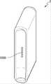
図18A及び図18Bは、クレードルの一例をさまざまな側面で図示した図面である。 18A and 18B are various views of an exemplary cradle.
図18Aは、クレードル2を第1方向から見た例を図示した図面である。クレードル2の一側面には、ホルダ1が挿入される空間2230がある。また、クレードル2がふたのような別途の固定手段を含まないとしても、ホルダ1がクレードル2に挿入されて固定される。また、クレードル2には、ユーザがクレードル2を制御することができるボタン2240、及び画面(image)が出力されるディスプレイ2250が含まれもする。 FIG. 18A is a drawing showing an example of the
図18Bは、クレードル2を第2方向から見た例を図示した図面である。クレードル2には、挿入されたホルダ1と結合される端子2260を含んでもよい。端子2260がホルダ1の端子2170と結合することにより、クレードル2のバッテリ210が供給する電力により、ホルダ1のバッテリ110が充電される。また、端子2170と端子2260とを介して、クレードル2のバッテリ210が供給する電力により、ホルダ1が動作することもでき、ホルダ1とクレードル2との信号送受信が可能である。例えば、端子2260は、4個のマイクロピン(pin)によっても構成されるが、それに限定されるものではない。 FIG. 18B is a drawing illustrating an example of the
図15ないし図18Bを参照して述べたように、ホルダ1は、クレードル2の内部空間2230に挿入される。また、ホルダ1は、クレードル2の内部に完全に挿入され、クレードル2に挿入された状態でもチルトされる。以下、図19及び図21Bを参照し、ホルダ1がクレードル2に挿入される例について説明する。 The
図19は、ホルダがクレードルに挿入される一例を図示した図面である。 FIG. 19 is a drawing illustrating an example in which the holder is inserted into the cradle.
図19を参照すれば、ホルダ1がクレードル2に挿入された一例が図示されている。ホルダ1が挿入される空間2230がクレードル2の一側面に存在するので、挿入されたホルダ1は、クレードル2の他の側面によって外部に露出されない。従って、クレードル2は、ホルダ1を外部に露出させないための他の構成(例えば、ふた)を含まなくともよい。 Referring to FIG. 19, an example in which the
クレードル2には、ホルダ1との結着強度を高めるために、少なくとも1つの結着部材2271,2272が含まれもする。また、ホルダ1にも、少なくとも1つの結着部材2181が含まれもする。ここで、結着部材2181,2271,2272は、磁石にもなるが、それに限定されるものではない。図19には、説明の便宜のために、ホルダ1が1つの結着部材2181を含み、クレードル2が2つの結着部材2271,2272を含むように図示されているが、結着部材2181,2271,2272の数は、それに限定されるものではない。 The
ホルダ1は、第1位置に、結着部材2181を含んでもよく、クレードル2は、第2位置及び第3位置に、それぞれ結着部材2271,2272を含んでもよい。そのとき、第1位置と第3位置は、ホルダ1がクレードル2に挿入される場合、互いに対面する位置でもある。 The
ホルダ1及びクレードル2に結着部材2181,2271,2272が含まれることにより、ホルダ1がクレードル2の一側面に挿入されても、ホルダ1とクレードル2とがさらに強く結着される。言い換えれば、ホルダ1及びクレードル2に、端子2170,2260以外に、結着部材2181,2271,2272がさらに含まれることにより、ホルダ1とクレードル2とがさらに強く結着される。従って、クレードル2に別途の構成(例えば、ふた)がないとしても、挿入されたホルダ1が、クレードル2から容易に分離されない。 Since the binding
また、端子2170,2260及び/または結着部材2181,2271,2272により、ホルダ1がクレードル2に完全に挿入されたと判断されれば、制御部220は、バッテリ210の電力を利用し、ホルダ1のバッテリ110を充電することができる。 Further, when it is determined that the
図20は、ホルダがクレードルに挿入された状態でチルトされる一例を図示した図面である。 FIG. 20 is a diagram illustrating an example in which the holder is tilted while being inserted into the cradle.
図20を参照すれば、ホルダ1がクレードル2の内部でチルトされている。ここで、該チルトは、ホルダ1がクレードル2に挿入された状態から一定角度傾けられることを意味する。 Referring to FIG. 20,
図19に図示されているように、ホルダ1がクレードル2に完全に挿入される場合、ユーザは、喫煙をすることができない。言い換えれば、ホルダ1がクレードル2に完全に挿入されれば、ホルダ1にシガレットが挿入されない。従って、ホルダ1がクレードル2に完全に挿入された状態においては、ユーザが喫煙をすることができない。 When the
図20に図示されているように、ホルダ1がチルトされれば、ホルダ1の末端2141が外部に露出される。従って、ユーザは、末端2141にシガレットを挿入し、生成されたエアロゾルを吸入(喫煙)することができる。チルト角θは、シガレットがホルダ1の末端2141に挿入されるとき、シガレットが折れたり毀損されたりしないように、十分な角度が確保される。例えば、ホルダ1は、末端2141に含まれたシガレット挿入孔全体が外部に露出される最小角度、またはそれより大きい角度にもチルトされる。例えば、チルト角θの範囲は、0゜超過180゜以下にもなり、望ましくは、10゜以上90゜以下にもなる。さらに望ましくは、チルト角θの範囲は、10゜以上20゜以下、10゜以上30゜以下、10゜以上40゜以下、10゜以上50゜以下、または10゜以上60゜以下にもなる。 As shown in FIG. 20, when the
また、ホルダ1がチルトされても、ホルダ1の端子2170と、クレードル2の端子2260は、互いに結合されている。従って、ホルダ1のヒータ2130は、クレードル2のバッテリ210が供給する電力によって加熱されもする。従って、ホルダ1のバッテリ110の残量が少ないか、あるいはない場合にも、ホルダ1は、クレードル2のバッテリ210を利用し、エアロゾルを生成することができる。 Moreover, even if the
図20には、ホルダ1が1つの結着部材2182を含み、クレードル2が2つの結着部材2273,2274を含む例が図示されている。例えば、結着部材2182,273,2274それぞれの位置は、図19を参照して説明した通りである。もし結着部材2182,273,2274が磁石であると仮定するならば、結着部材2274の磁石強度が、結着部材2273の磁石強度よりも大きくなる。従って、ホルダ1がチルトされても、結着部材182及び結着部材2274により、ホルダ1は、クレードル2と完全に分離されない。 FIG. 20 shows an example in which the
また、端子2170,2260及び/または結着部材2182,273,2274により、ホルダ1がチルトされたと判断されれば、制御部220は、バッテリ210の電力を利用し、ホルダ1のヒータ2130を加熱したり、バッテリ110を充電したりすることができる。 Further, when it is determined that the
図21A及び図21Bは、ホルダがクレードルに挿入された例を図示した図面である。 21A and 21B are diagrams illustrating an example in which the holder is inserted into the cradle.
図21Aには、ホルダ1がクレードル2に完全に挿入された例が図示されている。ホルダ1がクレードル2に完全に挿入される場合、ユーザがホルダ1に接触することを最小化させるために、クレードル2の内部空間2230が十分に確保されるようにも作製される。ホルダ1がクレードル2に完全に挿入されれば、制御部220は、ホルダ1のバッテリ110が充電されるように、バッテリ210の電力をホルダ1に供給する。 FIG. 21A shows an example in which the
図21Bには、ホルダ1がクレードル2に挿入された状態でチルトされた例が図示されている。ホルダ1がチルトされれば、制御部220は、ホルダ1のバッテリ110が充電されるか、あるいはホルダ1のヒータ2130が加熱されるように、バッテリ210の電力をホルダ1に供給する。 FIG. 21B shows an example in which the
図22は、ホルダ及びクレードルが動作する一例について説明するためのフローチャートである。 FIG. 22 is a flowchart for explaining an example of how the holder and cradle operate.
図22に図示されたエアロゾルを生成する方法は、図15に図示されたホルダ1、または図17に図示されたクレードル2において、時系列的に処理される段階で構成される。従って、以下で省略された内容であるとしても、図15に図示されたホルダ1、及び図17に図示されたクレードル2について、以上で記述された内容は、図22の方法にも適用されるということが分かる。 The method of generating an aerosol illustrated in FIG. 22 is composed of stages processed in chronological order in the
2710段階において、ホルダ1は、クレードル2に挿入されたか否かということを判断する。例えば、制御部120は、ホルダ1及びクレードル2の端子2170,2260が互いに連結されたか否かということ、及び/または結着部材2181,2271,2272が動作するか否かということにより、ホルダ1がクレードル2に挿入されたか否かということを判断することができる。 At
ホルダ1がクレードル2に挿入された場合には、2720段階に進み、ホルダ1がクレードル2から分離された場合には、2730段階に進む。 If the
2720段階において、クレードル2は、ホルダ1がチルトされたか否かということを判断する。例えば、制御部220は、ホルダ1及びクレードル2の端子2170,2260が互いに連結されたか否かということ、及び/または結着部材2182,273,2274が動作するか否かということにより、ホルダ1がチルトされたか否かということを判断することができる。 At
2720段階においては、クレードル2がホルダ1のチルトいかんを判断すると説明したが、それに限定されるものではない。言い換えれば、ホルダ1のチルトいかんは、ホルダ1の制御部120によっても判断される。 Although it has been described that the
ホルダ1がチルトされた場合には、2740段階に進み、ホルダ1がチルトされていない場合(すなわち、ホルダ1がクレードル2に完全に挿入された場合)には、2770段階に進む。 If
2730段階において、ホルダ1は、ホルダ1の使用条件を満足するか否かということを判断する。例えば、制御部120は、バッテリ110の残量、及びホルダ1の他の構成が正常に動作することができるか否かということをチェックすることにより、使用条件が満足されたか否かということを判断することができる。 In
ホルダ1の使用条件が満足された場合には、2740段階に進み、そうではない場合には、手続きを終了する。 If the conditions for using
2740段階において、ホルダ1は、ユーザに使用可能状態であるということを知らせる。例えば、制御部120は、ホルダ1のディスプレイに使用可能であるということを知らせる画面(image)を出力することもでき、ホルダ1のモータを制御し、振動信号を生成することもできる。 At
2750段階において、ヒータ2130が加熱される。一例として、ホルダ1がクレードル2から分離された場合、ホルダ1のバッテリ110の電力により、ヒータ2130が加熱されもする。他の例として、ホルダ1がチルトされた場合、クレードル2のバッテリ210の電力により、ヒータ2130が加熱されもする。 At
ホルダ1の制御部120、またはクレードル2の制御部220は、ヒータ2130の温度をリアルタイムで確認し、ヒータ2130に供給される電力の量、及びヒータ2130に電力が供給される時間を調節することができる。例えば、制御部120,220は、ホルダ1に含まれた温度感知センサ、またはヒータ2130の電気伝導性トラックを介して、ヒータ2130の温度をリアルタイムで確認することができる。 The
2760段階において、ホルダ1は、エアロゾル生成メカニズムを遂行する。例えば、制御部120,220は、ユーザがパフを遂行することによって変わるヒータ2130の温度を確認し、ヒータ2130に供給される電力の量を調節するか、あるいはヒータ2130に電力の供給を中断することができる。また、制御部120,220は、ユーザのパフ回数を計数することができ、一定パフ回数(例えば、1,500回)に逹すれば、ホルダの掃除が必要であるということを知らせる情報を出力することができる。 At
2770段階において、クレードル2は、ホルダ1の充電を行う。例えば、制御部220は、クレードル2のバッテリ210電力を、ホルダ1のバッテリ110に供給することにより、ホルダ1を充電させることができる。 At
一方、制御部120,220は、ユーザのパフ回数、またはホルダ1の動作時間により、ホルダ1の動作を停止させることもできる。以下、図23を参照し、制御部120,220がホルダ1の動作を停止させる一例について説明する。 On the other hand, the
図23は、ホルダが動作する他の例について説明するためのフローチャートである。 FIG. 23 is a flowchart for explaining another example of how the holder operates.
図23に図示されたエアロゾルを生成する方法は、図15に図示されたホルダ1、及び図17に図示されたクレードル2において、時系列的に処理される段階によって構成される。従って、以下で省略された内容であるとしても、図15に図示されたホルダ1、または図17に図示されたクレードル2について、以上で記述された内容は、図23の方法にも適用されるということが分かる。 The method of generating an aerosol illustrated in FIG. 23 consists of stages processed in chronological order in a
2810段階において、制御部120,220は、ユーザがパフしたか否かということを判断する。例えば、制御部120,220は、ホルダ1に含まれたパフ感知センサを介して、ユーザがパフしたか否かということを判断することができる。 At
2820段階において、ユーザのパフにより、エアロゾルが生成される。制御部120,220が、ユーザのパフ、及びヒータ2130の温度により、ヒータ2130に供給される電力を調節することができることは、図22を参照して説明した通りである。また、制御部120,220は、ユーザのパフ回数を計数する。 At
2830段階において、制御部120,220は、ユーザのパフ回数が、パフ制限回数以上であるか否かということを判断する。例えば、パフ制限回数が14回に設定されたと仮定すれば、制御部120,220は、計数されたパフ回数が14回以上であるか否かということを判断する。 At
一方、ユーザのパフ回数がパフ制限回数に近接した場合(例えば、ユーザのパフ回数が12回である場合)、制御部120,220は、ディスプレイまたは振動モータを介して、警告信号を出力することができる。 On the other hand, when the user's number of puffs approaches the limit number of puffs (for example, when the user's number of puffs is 12), the
もしユーザのパフ回数がパフ制限回数以上である場合には、2850段階に進み、ユーザのパフ回数がパフ制限回数より少ない場合には、2840段階に進む。 If the user's number of puffs is greater than or equal to the puff limit, the process proceeds to step 2850; otherwise, the process proceeds to step 2840.
2840段階において、制御部120,220は、ホルダ1が動作した時間が動作制限時間以上であるか否かということ判断する。ここで、ホルダ1が動作した時間は、ホルダが動作を始めた時点から現在まで累積された時間を意味する。例えば、動作制限時間が10分に設定されたと仮定すれば、制御部120,220は、ホルダ1が10分以上動作しているか否かということを判断する。 At
一方、ホルダ1の動作時間が動作制限時間に近接した場合(例えば、ホルダ1が8分間動作している場合)、制御部120,220は、ディスプレイまたは振動モータを介して、警告信号を出力することができる。 On the other hand, when the operating time of the
もしホルダ1が動作制限時間以上動作している場合には、2850段階に進み、ホルダ1の動作時間が動作制限時間より少ない場合には、2820段階に進む。 If the
2850段階において、制御部120,220は、ホルダの動作を強制終了する。言い換えれば、制御部120,220は、ホルダのエアロゾル生成メカニズムを停止させる。例えば、制御部120,220は、ヒータ2130に供給される電力を遮断することにより、ホルダの動作を強制終了することができる。 At
図24は、クレードルが動作する一例について説明するためのフローチャートである。 FIG. 24 is a flowchart for explaining an example of how the cradle operates.
図24に図示されたフローチャートは、図17に図示されたクレードル2において、時系列的に処理される段階によって構成される。従って、以下で省略された内容であるとしても、図17に図示されたクレードル2について以上で記述された内容は、図24のフローチャートにも適用されるということが分かる。 The flow chart shown in FIG. 24 is composed of steps processed in chronological order in the
図24には、図示されていないが、以下で説明するクレードル2の動作は、ホルダ1がクレードル2に挿入されたか否かということを問わずに遂行されもする。 Although not shown in FIG. 24, the operation of the
2910段階において、クレードル2の制御部220は、ボタン2240が押されたか否かということを判断する。もしボタン2240が押された場合には、2920段階に進み、ボタン2240が押されていない場合には、2930段階に進む。 At
2920段階において、クレードル2は、バッテリの状態を表示する。例えば、制御部220は、バッテリ210の現在状態(例えば、残量など)に係わる情報をディスプレイ2250に出力することができる。 At
2930段階において、クレードル2の制御部220は、クレードル2にケーブルが連結されたか否かということを判断する。例えば、制御部220は、クレードル2に含まれたインターフェース(例えば、USBポートなど)にケーブルが連結されたか否かということを判断する。もしクレードル2にケーブルが連結された場合には、2940段階に進み、そうではない場合には、手続きを終了する。 At
2940段階において、クレードル2は、充電動作を遂行する。例えば、クレードル2は、連結されたケーブルを介して供給される電力を利用し、バッテリ210を充電する。 At
図15を参照して説明した通り、ホルダ1には、シガレットが挿入される。シガレットは、エアロゾル生成物質を含み、加熱されたヒータ2130によってエアロゾルが生成される。 A cigarette is inserted into the
以下、図25ないし図27Fを参照し、ホルダ1に挿入されるシガレットの例について説明する。 Examples of cigarettes inserted into the
図25は、ホルダにシガレットが挿入された一例を図示した図面である。 FIG. 25 is a drawing illustrating an example in which a cigarette is inserted into a holder.
図25を参照すれば、シガレット3は、ケース2140の末端2141を介して、ホルダ1に挿入される。シガレット3が挿入されれば、ヒータ2130は、シガレット3の内部に位置する。従って、加熱されたヒータ2130により、シガレット3のエアロゾル生成物質が加熱され、それによってエアロゾルが生成される。 Referring to FIG. 25,
シガレット3は、一般的な燃焼型シガレットと類似している。例えば、シガレット3は、エアロゾル生成物質を含む第1部分3310と、フィルタなどを含む第2部分3320とに区分される。一方、一実施形態によるシガレット3は、第2部分3320に、エアロゾル生成物質を含んでもよい。例えば、顆粒またはカプセルの形態に作ったエアロゾル生成物質が、第2部分3320にも挿入される。
ホルダ1の内部には第1部分3310全体が挿入され、第2部分3320は、外部にも露出される。または、ホルダ1の内部に、第1部分3310の一部だけ挿入され、第1部分3310及び第2部分3320の一部が挿入されもする。 The entire
ユーザは、第2部分3320を口にした状態でエアロゾルを吸入することができる。このとき、該エアロゾルは、外部空気と混合され、ユーザの口に伝達される。図25に図示されているように、外部空気は、シガレット3の表面に形成された少なくとも1つの孔(hole)を介しても流入され(3110)、ホルダ1に形成された少なくとも1つの空気通路を介しても流入される(3120)。例えば、ホルダ1に形成された空気通路は、ユーザによって開閉されるようにも作製される。 The user can inhale the aerosol with the
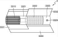
図26A及び図26Bは、シガレットの一例を図示した構成図である。 26A and 26B are configuration diagrams illustrating examples of cigarettes.
図26A及び図26Bを参照すれば、シガレット3は、タバコロッド3300、第1フィルタセグメント3321、冷却構造物3322及び第2フィルタセグメント3323を含む。図25を参照して説明した第1部分3310は、タバコロッド3300を含み、第2部分3320は、第1フィルタセグメント3321、冷却構造物3322及び第2フィルタセグメント3323を含む。 26A and 26B,
一方、図26A及び図26Bを比較すれば、図26Bのシガレット3は、図26Aのシガレット3に比べ、第4ラッパ3334をさらに含む。 On the other hand, comparing FIGS. 26A and 26B, the
ただし、図26A及び図26Bに図示されたシガレット3の構造は、一例に過ぎず、一部構成が省略されもする。例えば、シガレット3には、第1フィルタセグメント3321、冷却構造物3322及び第2フィルタセグメント3323のうち1以上が含まれなくともよい。 However, the structure of the
タバコロッド3300は、エアロゾル生成物質を含む。例えば、該エアロゾル生成物質は、グリセリン、プロピレングリコール、エチレングリコール、ジプロピレングリコール、ジエチレングリコール、トリエチレングリコール、テトラエチレングリコール及びオレイルアルコールのうち少なくとも一つを含んでもよい。タバコロッド3300の長さは、約7mmないし15mmでもあるか、あるいは望ましくは、約12mmにもなる。また、タバコロッド3300の直径は、7mmないし9mmでもあるか、あるいは望ましくは、約7.9mmでもある。タバコロッド3300の長さ及び直径は、前述の数値範囲に限定されるものではない。 Tobacco rod 3300 includes an aerosol-forming material. For example, the aerosol-forming material may include at least one of glycerin, propylene glycol, ethylene glycol, dipropylene glycol, diethylene glycol, triethylene glycol, tetraethylene glycol and oleyl alcohol. The length of tobacco rod 3300 is also between about 7 mm and 15 mm, or preferably as much as about 12 mm. Also, the diameter of tobacco rod 3300 is between 7 mm and 9 mm, or preferably about 7.9 mm. The length and diameter of tobacco rod 3300 are not limited to the numerical ranges described above.
また、タバコロッド3300は、風味剤、湿潤剤及び/またはアセテート化合物のような他の添加物質を含んでもよい。例えば、該風味剤は、甘草、ショ糖、果糖シロップ、イソ甘味剤(isosweet)、ココア、ラベンダ、シナモン、カルダモン、セロリ、フェヌグリーク、カスカリラ、白檀、ベルガモット、ゼラニウム、蜂蜜エッセンス、ローズオイル、バニラ、レモンオイル、オレンジオイル、ミントオイル、桂皮、キャラウェイ、コニャック、ジャスミン、カモマイル、メントール、桂皮、イランイラン、ザルビア、スペアミント、生姜、コリアンダまたはコーヒーなどを含んでもよい。また、該湿潤剤は、グリセリンまたはプロピレングリコールなどを含んでもよい。 Tobacco rod 3300 may also include other additive substances such as flavorants, humectants and/or acetate compounds. For example, the flavors include licorice, sucrose, fructose syrup, isosweet, cocoa, lavender, cinnamon, cardamom, celery, fenugreek, cascara, sandalwood, bergamot, geranium, honey essence, rose oil, vanilla, Lemon oil, orange oil, mint oil, cinnamon bark, caraway, cognac, jasmine, chamomile, menthol, cinnamon bark, ylang ylang, zarubia, spearmint, ginger, coriander or coffee may be included. The humectant may also include glycerin or propylene glycol, and the like.
一例として、タバコロッド3300は、刻みタバコによっても充填される。ここで、該刻みタバコは、タバコシートを細かく粉砕することによっても生成される。 As an example, tobacco rod 3300 is also filled with cut tobacco. Here, the cut tobacco is also produced by finely pulverizing tobacco sheets.
広いタバコシートが狭い空間のタバコロッド3300に充填されるためには、タバコシートが容易に折り畳まれるようにする工程が追加して要求される。従って、タバコロッド3300をタバコシートで充填することに比べ、タバコロッド3300を刻みタバコで充填する方がさらに容易であり、タバコロッド3300を生産する工程の生産性及び効率がさらに高くなる。 In order to fill the narrow tobacco rod 3300 with a wide tobacco sheet, a process for easily folding the tobacco sheet is additionally required. Therefore, it is easier to fill the tobacco rod 3300 with cut tobacco than it is to fill the tobacco rod 3300 with tobacco sheets, making the process of producing the tobacco rod 3300 more productive and efficient.
他の例として、タバコロッド3300は、タバコシートが細切りされた複数のタバコ筋によっても充填される。例えば、タバコロッド3300は、複数のタバコ筋が互いに同じ方向(平行)、または無作為に合わされても形成される。1本のタバコ筋は、横長が1mm、縦長が12mm、厚み(高さ)が0.1mmである直方体状にも製造されるが、それに限定されるものではない。 As another example, the tobacco rod 3300 may also be filled with a plurality of strips of shredded tobacco sheet. For example, the tobacco rod 3300 can be formed by aligning multiple tobacco strands in the same direction (parallel) or randomly. A single tobacco strip may be manufactured in a rectangular parallelepiped shape having a horizontal length of 1 mm, a vertical length of 12 mm, and a thickness (height) of 0.1 mm, but is not limited thereto.
タバコロッド3300がタバコシートによって充填されることに比べ、タバコ筋によって充填されたタバコロッド3300は、さらに多量のエアロゾルが発生する。同一空間に充填されることを仮定すれば、タバコシートに比べ、タバコ筋がさらに広い表面積を保証する。広い表面積は、エアロゾル生成物質が外部空気と接触する機会がさらに多いということを意味する。従って、タバコロッド3300がタバコ筋によって充填される場合、タバコシートに充填されたことに比べ、さらに多くのエアロゾルが生成される。 A tobacco rod 3300 filled with tobacco streaks generates a greater amount of aerosol than a tobacco rod 3300 filled with tobacco sheets. Assuming the same space is packed, the tobacco strands guarantee a larger surface area than the tobacco sheet. A large surface area means that the aerosol-forming material has a greater chance of coming into contact with the outside air. Therefore, when the tobacco rod 3300 is loaded with tobacco streaks, more aerosol is generated than when loaded with tobacco sheets.
また、シガレット3をホルダ1から分離するとき、タバコ筋に充填されたタバコロッド3300が、タバコシートに充填されたものに比べ、さらに容易に分離される。タバコシートに比べ、タバコ筋がヒータ2130と接触して生成される摩擦力がさらに小さい。従って、タバコロッド3300がタバコ筋によって充填される場合、タバコシートによって充填されたものに比べ、ホルダ1からさらに容易に分離される。 Further, when the
該タバコシートは、タバコ原料をスラリー形態に粉砕した後、該スラリーを乾燥させることによっても形成される。例えば、該スラリーには、エアロゾル生成物質が15ないし30%添加される。タバコ原料は、タバコ葉切れ、タバコ茎、タバコ処理中に発生されたタバコ粉じん、及び/またはタバコ葉の主要脇片ストリップでもある。また、タバコシートには、木材セルロース纎維のような他の添加剤が含有されてもよい。 The tobacco sheet is also formed by grinding the tobacco material into a slurry form and then drying the slurry. For example, 15-30% aerosol-forming material is added to the slurry. Tobacco raw material may also be tobacco leaf cuts, tobacco stems, tobacco dust generated during tobacco processing, and/or primary side strips of tobacco leaf. The tobacco sheet may also contain other additives such as wood cellulose fibers.
第1フィルタセグメント3321は、セルロースアセテートフィルタでもある。例えば、第1フィルタセグメント3321は、内部に空洞を含むチューブ形態でもある。第1フィルタセグメント3321の長さは、約7mmないし15mmでもあるか、あるいは望ましくは、約7mmにもなる。第1フィルタセグメント3321の長さは、約7mmより短いが、少なくとも1つのシガレット要素(例えば、冷却要素、カプセル、アセテートフィルタなど)の機能が毀損されないほどの長さを有することが望ましい。第1フィルタセグメント3321の長さは、前述の数値範囲に限定されるものではない。一方、第1フィルタセグメント3321の長さは、拡張可能であり、第1フィルタセグメント3321の長さにより、シガレット3全体長が調節される。 The
第2フィルタセグメント3323も、セルロースアセテートフィルタでもある。例えば、第2フィルタセグメント3323は、空洞を含むリセスフィルタによっても作製されるが、それに限定されるものではない。第2フィルタセグメント3323の長さは、約5mmないし15mmでもあるか、あるいは望ましくは、約12mmにもなる。第2フィルタセグメント3323の長さは、前述の数値範囲に限定されるものではない。 The
また、第2フィルタセグメント3323には、少なくとも1つのカプセル3324が含まれてもよい。ここで、カプセル3324は、香料を含む内容液を被膜で覆い包んだ構造でもある。例えば、カプセル3324は、球形または円筒状の形状を有することができる。カプセル3324の直径は、2mm以上でもあるが、あるいは望ましくは、2~4mmでもある。
カプセル3324の被膜を形成する材料は、澱粉及び/またはゲル化剤でもある。例えば、ゲル化剤としては、ゲランガムやゼラチンが使用される。また、カプセル3324の被膜を形成する材料として、ゲル化助剤がさらに利用される。ここで、該ゲル化助剤としては、例えば、塩化カルシウムが使用される。また、カプセル3324の被膜を形成する材料として、可塑剤がさらに利用される。ここで、該可塑剤としては、グリセリン及び/またはソルビトールが利用される。また、カプセル3324の被膜を形成する材料として、着色料がさらに利用される。 The material forming the coating of
例えば、カプセルの内容液に含まれる香料としては、メントール、植物の精油などが利用される。また、該内容液に含まれる香料の溶媒としては、例えば、重鎖脂肪酸トリグリセリド(重鎖)が利用される。また、該内容液は、色素、乳化剤、増粘剤のような他の添加剤を含んでもよい。 For example, menthol, essential oils of plants, and the like are used as fragrances contained in the liquid content of the capsule. Further, as a solvent for the perfume contained in the content liquid, for example, a heavy chain fatty acid triglyceride (heavy chain) is used. The content liquid may also contain other additives such as pigments, emulsifiers and thickeners.
冷却構造物3322は、ヒータ2130が、タバコロッド3300を加熱することによって生成されたエアロゾルを冷却させる。従って、ユーザは、適当な温度に冷却されたエアロゾルを吸入することができる。冷却構造物3322の長さは、約10mmないし20mmでもあるか、あるいは望ましくは、約14mmにもなる。冷却構造物3322の長さは、前述の数値範囲に限定されるものではない。
例えば、冷却構造物3322は、ポリ乳酸によっても作製される。冷却構造物3322は、単位面積当たり表面積(すなわち、エアロゾルと接触する表面積)を拡大させるために、多様な形態にも作製される。冷却構造物3322の多様な例は、図27Aないし図27Fを参照して後述する。 For example,
タバコロッド3300及び第1フィルタセグメント3321は、第1ラッパ3331によっても包装される。例えば、第1ラッパ3331は、耐油性を有する紙類包装材によっても作製される。 Tobacco rod 3300 and
冷却構造物3322及び第2フィルタセグメント3323は、第2ラッパ3332によっても包装される。また、シガレット3全体は、第3ラッパ3333によっても再包装される。例えば、第2ラッパ3332及び第3ラッパ3333は、一般的な紙類包装材によっても作製される。選択的には、第2ラッパ3332は、耐油ハード巻紙またはPLA加香紙でもある。また、第2ラッパ3332は、第2フィルタセグメント3323部分を包装し、追加して第2フィルタセグメント3323及び冷却構造物3322をさらに包装することができる。 The
図26Bを参照すれば、シガレット3は、第4ラッパ3334を含んでもよい。タバコロッド3300と第1フィルタセグメント3321とのうち少なくとも一つは、第4ラッパ3334によっても包装される。言い換えれば、タバコロッド3300だけ第4ラッパ3334によっても包装され、タバコロッド3300及び第1フィルタセグメント3321が第4ラッパ3334によっても包装される。例えば、第4ラッパ3334は、紙類包装材によっても作製される。 Referring to FIG. 26B,
第4ラッパ3334は、紙類包装材の一表面または両表面に、所定物質が塗布(または、コーティング)されることによって生成される。ここで、所定物質の例としては、シリコンが該当するが、それに限定されるものではない。シリコンは、温度による変化が少ない耐熱性、酸化されない耐酸化性、各種薬品に対する抵抗性、水に対する撥水性、または電気絶縁性などの特性を有する。ただし、シリコンではないとしても、前述の特性を有する物質であるならば、制限なしに第4ラッパ3334に塗布(または、コーティング)される。 The
一方、図26Bには、シガレット3が第1ラッパ3331及び第4ラッパ3334をいずれも含むように図示されているが、それに限定されるものではない。言い換えれば、シガレット3が第1ラッパ3331及び第4ラッパ3334のうちいずれか一つだけ含んでもよい。 On the other hand, FIG. 26B illustrates the
第4ラッパ3334は、シガレット3が燃焼される現象を防止することができる。例えば、タバコロッド3300がヒータ2130によって加熱されれば、シガレット3が燃焼される可能性がある。具体的には、タバコロッド3300に含まれた物質のうちいずれか1つの発火点以上に温度が上昇する場合、シガレット3が燃焼される。そのような場合にも、第4ラッパ3334は、不燃性物質を含むので、シガレット3が燃焼される現象が防止される。 The
また、第4ラッパ3334は、シガレット3で生成される物質によってホルダ1が汚染されることを防止することができる。ユーザのパフにより、シガレット3内で液体物質が生成されもする。例えば、シガレット3で生成されたエアロゾルが外部空気によって冷却されることにより、液体物質(例えば、水分など)が生成される。第4ラッパ3334が、タバコロッド3300及び/または第1フィルタセグメント3321を包装することにより、シガレット3内で生成された液体物質が、シガレット3の外部に漏れることが防止される。従って、ホルダ1のケース2140などが、シガレット3で生成された液体物質によって汚染される現象が防止される。 In addition, the
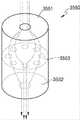
図27Aないし図27Fは、シガレットの冷却構造物の例を図示した図面である。 27A-27F are diagrams illustrating examples of cigarette cooling structures.
例えば、図27Aないし図27Fに図示された冷却構造物は、純粋なポリ乳酸(PLA)によって生産された纎維を利用しても作製される。 For example, the cooling structures illustrated in Figures 27A-27F are also made using fibers produced by pure polylactic acid (PLA).
一例として、フィルム(シート)を充填し、冷却構造物のフィルム(シート)を作製する場合、フィルム(シート)が外部の衝撃によって裂けてしまう。その場合、冷却構造物がエアロゾルを冷却する効果が低減される。 As an example, when filling a film (sheet) to produce a film (sheet) of a cooling structure, the film (sheet) is torn by an external impact. In that case, the cooling structure's effectiveness in cooling the aerosol is reduced.
他の例として、押出成形などによって冷却構造物を作製する場合、構造物の切断などの工程が追加されることにより、工程の効率が低くなる。また、該冷却構造物を多様な形状で作製することにも限界がある。 As another example, when manufacturing cooling structures such as by extrusion, additional steps such as cutting the structure reduce the efficiency of the process. Also, there is a limit to fabricating the cooling structure in a variety of shapes.
一実施形態による冷却構造物を、ポリ乳酸纎維を利用して作製する(例えば、織造)ことにより、冷却構造物が外部衝撃によって変形されたり、機能を喪失したりするようになる危険性が低くなる。また、纎維を組み合わせる方式を変更することにより、多様な形状を有する冷却構造物を作製することができる。 By fabricating (e.g., weaving) the cooling structure according to one embodiment using polylactic acid fibers, there is no risk that the cooling structure will be deformed or lose its function due to external impact. lower. In addition, cooling structures having various shapes can be manufactured by changing the method of combining the fibers.
また、纎維を利用し、冷却構造物を作製することにより、エアロゾルと接触する表面積が拡大される。従って、冷却構造物のエアロゾル冷却効果がさらに向上する。 Also, the use of fibers to create cooling structures increases the surface area in contact with the aerosol. Therefore, the aerosol cooling effect of the cooling structure is further enhanced.
図27Aを参照すれば、冷却構造物3510は、円筒状にも作製され、冷却構造物3510の断面には、少なくとも1つの空気通路3511が形成されるようにも作製される。 Referring to FIG. 27A, the
図27Bを参照すれば、冷却構造物3520は、複数の纎維が互いに編み上げられた構造物にも作製される。このとき、エアロゾルは、纎維間に流れ、冷却構造物3520の形態によって渦流が形成される。形成された渦流は、冷却構造物3520において、エアロゾルが接触する面積を広げ、エアロゾルが冷却構造物3520内に留まる時間を延長させる。従って、加熱されたエアロゾルが、効果的に冷却される。 Referring to FIG. 27B, the
図27Cを参照すれば、冷却構造物3530は、複数個の束3531が集められた形態にも作製される。 Referring to FIG. 27C, the
図27Dを参照すれば、冷却構造物3540は、ポリ乳酸、刻みタバコまたは炭それぞれによって製造された顆粒によっても充填される。また、該顆粒は、ポリ乳酸、刻みタバコ及び炭の混合物によっても製造される。一方、該顆粒は、ポリ乳酸、刻みタバコ及び/または炭以外にも、エアロゾルの冷却効果を向上させることができる要素をさらに含んでもよい。 Referring to Figure 27D, the
図27Eを参照すれば、冷却構造物3550は、第1断面3551及び第2断面3552を含んでもよい。 Referring to FIG. 27E,
第1断面3551は、第1フィルタセグメント3321と接境し、エアロゾルが流入する空隙を含む。第2断面3552は、第2フィルタセグメント3323と接境し、エアロゾルが放出される空隙を含んでもよい。例えば、第1断面3551と第2断面3552は、直径が同一である単一空隙を含んでもよいが、第1断面3551と第2断面3552とに含まれる空隙の直径及び数は、それに制限されるものではない。 A
併せて、冷却構造物3550は、第1断面3551と第2断面3552との間に、複数の空隙が含まれた第3断面3553を含んでもよい。例えば、第3断面3553に含まれた複数の空隙の直径は、第1断面3551及び第2断面3552に含まれた空隙の直径よりも小さい。また、第3断面3553に含まれた空隙の数は、第1断面3551及び第2断面3552に含まれた空隙の数よりも多い。 In addition, the
図27Fを参照すれば、冷却構造物3560は、第1フィルタセグメント3321と接境する第1断面3561、及び第2フィルタセグメント3323と接境する第2断面3562を含んでもよい。また、冷却構造物3560は、1以上の管形要素3563を含んでもよい。例えば、管形要素3563は、第1断面3561と第2断面3562とを貫通ことができる。また、管形要素3563は、微細多孔質包装材によっても包装され、エアロゾルの冷却効果を向上させることができる充填材(例えば、図27Dを参照して説明した顆粒)によっても充填される。 27F, the
なお、前述の方法は、コンピュータで実行されるプログラムに作成可能であり、コンピュータで読み取り可能な記録媒体を利用し、前記プログラムを動作させる汎用デジタルコンピュータでも具現される。また、前述の方法で使用されたデータの構造は、コンピュータで読み取り可能な記録媒体に、さまざまな手段を介しても記録される。前記コンピュータで読み取り可能な記録媒体は、マグネチック保存媒体(例えば、ROM(read-only memory)、RAM(random access memory)、USB、フロッピー(登録商標)ディスク、ハードディスクなど)、光学的判読媒体(例えば、CD-ROM(compact disc read only memory)、DVD(digital versatile disc)など)のような記録媒体を含む。 The above method can be written as a computer-executable program, and can also be embodied in a general-purpose digital computer that operates the program using a computer-readable recording medium. The data structures used in the methods described above may also be recorded on computer readable recording media through various means. The computer-readable recording medium includes magnetic storage media (e.g., ROM (read-only memory), RAM (random access memory), USB, floppy (registered trademark) disk, hard disk, etc.), optically readable media ( For example, it includes a recording medium such as a CD-ROM (compact disc read only memory), a DVD (digital versatile disc), etc.).
本実施形態と係わる技術分野で当業者であるならば、前述の記載の本質的な特性から外れない範囲で変形された形態に具現されるということを理解することができるであろう。従って、開示された方法は、限定的な観点ではなく、説明的な観点から考慮されなければならない。本発明の範囲は、前述の説明ではなく、特許請求の範囲に示されており、それと同等な範囲内にある全ての差異は、本発明に含まれたものであると解釈されなければならないのである。 Those skilled in the art related to the present embodiments will understand that the present embodiments may be embodied in modified forms without departing from the essential characteristics described above. Accordingly, the disclosed method should be considered from an illustrative rather than a restrictive point of view. The scope of the invention is indicated by the appended claims rather than by the foregoing description, and all differences that come within the scope of equivalents thereof are to be construed as included in the present invention. be.
Claims (11)
Translated fromJapanese前記ユーザから喫煙開始のための要請を受信するインターフェースと、
前記喫煙パターンについてのデータに基づき、前記受信された要請が喫煙を制限するための喫煙制限条件を充足するか否かということを判断するコントローラと、
前記喫煙制限条件が充足されるか否かということにより、前記コントローラの制御により、エアロゾルを生成するための電力をバッテリから供給されたり、前記電力の供給が制限されたりするヒータと、を含み、
前記コントローラは、
あらかじめ設定された臨界期間の間、前記ユーザの喫煙回数があらかじめ設定された臨界回数に達した否かということに基づいて、前記喫煙制限条件を充足するか否かということを判断し、
前記喫煙制限条件が充足された喫煙制限モードである場合、前記喫煙制限条件が充足されていない喫煙モード下で制御される前記ヒータの温度範囲に比べ、低い温度範囲で前記ヒータが制御されるように前記電力の供給を制限し、
前記喫煙制限条件は、特定の喫煙が完了してから次の喫煙の開始までのインターバルが短い場合に前記次の喫煙を制限することをさらに含む、エアロゾル生成装置。a memory for storing data about a user's smoking pattern;
an interface for receiving a request to start smoking from the user;
a controller for determining whether the received request satisfies a smoking restriction condition for restricting smoking based on the data about the smoking pattern;
A heater to which power for generating aerosol is supplied from a battery or the power supply is restricted under the control of the controller depending on whether the smoking restriction condition is satisfied;
The controller is
determining whether or not the smoking restriction condition is satisfied based on whether the number of times the user smokes during a preset critical period has reached a preset critical number;
In a smoking restriction mode in which the smoking restriction condition is satisfied, the heater is controlled in a lower temperature range than a temperature range of the heater controlled in a smoking mode in which the smoking restriction condition is not satisfied. limiting the supply of said power to
The aerosol generating device, wherein the smoking restriction condition further includes restricting the next smoking when the interval from the completion of a specific smoking to the start of the next smoking is short.
前記喫煙制限モード下において、前記ヒータの加熱によって生成されるエアロゾルの量が、前記喫煙モード下において、前記ヒータの加熱によって生成されるエアロゾルの量より少なくなるための温度範囲であることを特徴とする請求項1に記載のエアロゾル生成装置。The lower temperature range is
The temperature range is such that the amount of aerosol generated by heating the heater under the restricted smoking mode is less than the amount of aerosol generated by heating the heater under the smoking mode. The aerosol generating device according to claim 1.
前記ヒータの予熱後、前記エアロゾルを生成させるために、一定範囲の温度に維持される区間で制御される温度範囲であることを特徴とする請求項1に記載のエアロゾル生成装置。The temperature range is
2. The aerosol generating apparatus according to claim 1, wherein after the heater is preheated, in order to generate the aerosol, the temperature range is controlled in a section in which the temperature is maintained within a certain range.
前記インターフェースを介したボタン入力、シガレット挿入及び抽出のセンシング、ヒータ温度変化によるパフのセンシング、及び流量変化によるパフのセンシングのうち少なくとも一つに基づいて、前記喫煙の開始と終了とを判断することにより、前記喫煙回数を計数することを特徴とする請求項1に記載のエアロゾル生成装置。The controller is
determining the start and end of smoking based on at least one of button input through the interface, cigarette insertion and extraction sensing, puff sensing by heater temperature change, and puff sensing by flow rate change. 2. The aerosol generating device according to claim 1, wherein the number of times of smoking is counted by:
前記喫煙制限条件が充足された喫煙制限モードである場合、ディスプレイ、ランプ、スピーカ及びモータ振動のうち少なくとも1つの手段を利用し、前記喫煙制限モードが活性化されたことを示すお知らせを提供することを特徴とする請求項1に記載のエアロゾル生成装置。The interface is
In the case of the restricted smoking mode in which the restricted smoking condition is satisfied, using at least one means of a display, a lamp, a speaker, and a motor vibration to provide a notification indicating that the restricted smoking mode has been activated. The aerosol generator according to claim 1, characterized by:
前記インターフェースを介して入力された設定情報、外部デバイスから無線通信によって受信された設定情報、及びクレードルデバイスに結合された状態で外部デバイスから有線通信によって受信された設定情報のうち少なくとも一つに基づいたものであることを特徴とする請求項1に記載のエアロゾル生成装置。The smoking restriction condition is
Based on at least one of setting information input through the interface, setting information received from an external device through wireless communication, and setting information received from an external device through wired communication while coupled to the cradle device 2. The aerosol generating device according to claim 1, wherein the aerosol generating device is a
ユーザの喫煙パターンをモニタリングする段階と、
前記ユーザから喫煙開始のための要請を受信する段階と、
前記喫煙パターンに対するモニタリングに基づき、前記受信された要請が喫煙を制限するための喫煙制限条件を充足するか否かということを判断する段階と、
前記喫煙制限条件が充足されるか否かということにより、エアロゾルを生成するための電力がバッテリからヒータに供給されたり、前記電力の供給が制限されたりするように、前記ヒータを制御する段階と、を含み、
前記判断する段階は、
あらかじめ設定された臨界期間の間、前記ユーザの喫煙回数があらかじめ設定された臨界回数に達したか否かということに基づいて、前記喫煙制限条件を充足するか否かということを判断し、
前記制御する段階は、
前記喫煙制限条件が充足された喫煙制限モードである場合、前記喫煙制限条件が充足されていない喫煙モード下で制御される前記ヒータの温度範囲に比べ、低い温度範囲で前記ヒータが制御されるように前記電力の供給を制限し、
前記喫煙制限条件は、特定の喫煙が完了してから次の喫煙の開始までのインターバルが短い場合に前記次の喫煙を制限することをさらに含む、方法。A method of providing a smoking restriction feature in an aerosol generating device comprising:
monitoring the user's smoking pattern;
receiving a request from the user to start smoking;
determining, based on the monitoring of the smoking pattern, whether the received request satisfies a smoking restriction condition for restricting smoking;
controlling the heater so that power for generating aerosol is supplied from a battery to the heater or the supply of power is restricted depending on whether the smoking restriction condition is satisfied; , including
The determining step includes:
determining whether the smoking restriction condition is satisfied based on whether the number of times the user smokes during a preset critical period has reached a preset critical number;
The controlling step includes:
In a smoking restriction mode in which the smoking restriction condition is satisfied, the heater is controlled in a lower temperature range than a temperature range of the heater controlled in a smoking mode in which the smoking restriction condition is not satisfied. limiting the supply of said power to
The method, wherein the limiting smoking condition further comprises limiting the next smoking if the interval from completion of a particular smoking to initiation of the next smoking is short.
前記喫煙制限モード下において、前記ヒータの加熱によって生成されるエアロゾルの量が、前記喫煙モード下において、前記ヒータの加熱によって生成されるエアロゾルの量より少なくなるための温度範囲であり、
前記温度範囲は、
前記ヒータの予熱後、前記エアロゾルを生成させるために一定範囲の温度に維持される区間で制御される温度範囲であることを特徴とする請求項7に記載の方法。The lower temperature range is
a temperature range in which the amount of aerosol generated by heating the heater under the restricted smoking mode is less than the amount of aerosol generated by heating the heater under the smoking mode;
The temperature range is
8. The method of claim 7, wherein after preheating the heater, the temperature range is controlled in intervals where the temperature is maintained within a range to generate the aerosol.
インターフェースを介したボタン入力、シガレット挿入及び抽出のセンシング、ヒータ温度変化によるパフのセンシング、及び流量変化によるパフのセンシングのうち少なくとも一つに基づいて、前記喫煙の開始と終了とを判断することによって計数されることを特徴とする請求項7に記載の方法。The number of smoking times
by determining the start and end of smoking based on at least one of button input via an interface, sensing cigarette insertion and extraction, puff sensing by heater temperature change, and puff sensing by flow rate change. 8. Method according to claim 7, characterized in that it is counted.
インターフェースを介して入力された設定、外部デバイスから無線通信によって受信された設定、及びクレードルデバイスに結合された状態で外部デバイスから有線通信によって受信された設定のうち少なくとも一つに基づいたものであることを特徴とする請求項7に記載の方法。
The smoking restriction condition is
It is based on at least one of settings input through an interface, settings received from an external device via wireless communication, and settings received from an external device via wired communication while coupled to the cradle device. 8. The method of claim 7, wherein:
Priority Applications (1)
| Application Number | Priority Date | Filing Date | Title |
|---|---|---|---|
| JP2021177649AJP7306773B2 (en) | 2017-04-11 | 2021-10-29 | AEROSOL GENERATING DEVICES AND METHODS OF PROVIDING SMOKING RESTRICTION FEATURES IN AEROSOL GENERATING DEVICES |
Applications Claiming Priority (7)
| Application Number | Priority Date | Filing Date | Title |
|---|---|---|---|
| KR20170046938 | 2017-04-11 | ||
| KR10-2017-0046938 | 2017-04-11 | ||
| KR10-2017-0077586 | 2017-06-19 | ||
| KR1020170077586AKR20180070436A (en) | 2016-12-16 | 2017-06-19 | Method and apparatus for generating generating aerosols |
| KR1020170084386AKR102135892B1 (en) | 2016-12-16 | 2017-07-03 | Aerosol generating apparatus and method for providig function of limiting smoking thereof |
| KR10-2017-0084386 | 2017-07-03 | ||
| PCT/KR2018/004129WO2018190589A2 (en) | 2017-04-11 | 2018-04-09 | Aerosol generating device and method for providing smoking restriction function in aerosol generating device |
Related Child Applications (1)
| Application Number | Title | Priority Date | Filing Date |
|---|---|---|---|
| JP2021177649ADivisionJP7306773B2 (en) | 2017-04-11 | 2021-10-29 | AEROSOL GENERATING DEVICES AND METHODS OF PROVIDING SMOKING RESTRICTION FEATURES IN AEROSOL GENERATING DEVICES |
Publications (2)
| Publication Number | Publication Date |
|---|---|
| JP2020518235A JP2020518235A (en) | 2020-06-25 |
| JP7180947B2true JP7180947B2 (en) | 2022-11-30 |
Family
ID=70727358
Family Applications (1)
| Application Number | Title | Priority Date | Filing Date |
|---|---|---|---|
| JP2019555169AActiveJP7180947B2 (en) | 2017-04-11 | 2018-04-09 | AEROSOL GENERATING DEVICES AND METHODS OF PROVIDING SMOKING RESTRICTION FEATURES IN AEROSOL GENERATING DEVICES |
Country Status (2)
| Country | Link |
|---|---|
| US (1) | US11771138B2 (en) |
| JP (1) | JP7180947B2 (en) |
Families Citing this family (35)
| Publication number | Priority date | Publication date | Assignee | Title |
|---|---|---|---|---|
| KR102832535B1 (en)* | 2018-07-31 | 2025-07-11 | 니뽄 다바코 산교 가부시키가이샤 | Charging device and information processing system |
| US11882438B2 (en)* | 2018-10-29 | 2024-01-23 | Zorday IP, LLC | Network-enabled electronic cigarette |
| KR102194731B1 (en) | 2018-11-16 | 2020-12-23 | 주식회사 케이티앤지 | Aerosol generating device that supplies power to two heaters with one battery |
| US11064727B2 (en)* | 2019-02-06 | 2021-07-20 | Altria Client Services Llc | Sensor apparatuses and systems |
| KR102252456B1 (en) | 2019-04-18 | 2021-05-14 | 주식회사 케이티앤지 | Method for counting puff and aerosol generating device using the same |
| KR102281296B1 (en) | 2019-06-17 | 2021-07-23 | 주식회사 케이티앤지 | Aerosol generating device and operation method thereof |
| KR20220081335A (en)* | 2019-10-16 | 2022-06-15 | 필립모리스 프로덕츠 에스.에이. | Aerosol-generating devices with modular components |
| KR102324197B1 (en) | 2020-02-07 | 2021-11-09 | 주식회사 케이티앤지 | Aerosol generating device |
| KR102479092B1 (en) | 2020-02-24 | 2022-12-19 | 주식회사 케이티앤지 | Aerosol generating device |
| KR102478152B1 (en) | 2020-03-02 | 2022-12-15 | 주식회사 케이티앤지 | Aerosol generating device and system |
| KR102427857B1 (en) | 2020-05-14 | 2022-08-01 | 주식회사 케이티앤지 | Aerosol generating system |
| IL298052A (en)* | 2020-06-10 | 2023-01-01 | Esmoking Inst Sp Z O O | Aerosol provision device |
| EP4175496A2 (en)* | 2020-07-06 | 2023-05-10 | JT International SA | Hollow tobacco rod (consumable) assembly and its fabrication method |
| GB202010610D0 (en)* | 2020-07-10 | 2020-08-26 | Nicoventures Trading Ltd | Aerosol provision system |
| KR102502754B1 (en) | 2020-08-19 | 2023-02-22 | 주식회사 케이티앤지 | Aerosol generating apparatus for detecting whether aerosol generating article is inserted therein and operation method of the same |
| KR102500830B1 (en)* | 2020-08-31 | 2023-02-16 | 주식회사 케이티앤지 | Aerosol generating apparatus including pressure sensor |
| JP6890203B1 (en) | 2020-09-30 | 2021-06-18 | 日本たばこ産業株式会社 | Power supply unit of aerosol generator |
| JP7520140B2 (en)* | 2020-11-10 | 2024-07-22 | 日本たばこ産業株式会社 | Information processing device, information processing method, and program |
| EP4245172A4 (en)* | 2020-11-10 | 2024-10-23 | Japan Tobacco Inc. | Information processing device, information processing method, and program |
| KR102522678B1 (en)* | 2020-12-31 | 2023-04-17 | 주식회사 케이티앤지 | Aerosol generating device |
| KR20220098932A (en)* | 2021-01-05 | 2022-07-12 | 주식회사 케이티앤지 | Aerosol generating apparatus and method controlling heating time of heater |
| GB202103375D0 (en)* | 2021-03-11 | 2021-04-28 | Nicoventures Trading Ltd | Aerosol provision system |
| KR20220161084A (en)* | 2021-05-28 | 2022-12-06 | 주식회사 케이티앤지 | Aerosol generating device comprising puff recognition function and method thereof |
| KR20220163161A (en)* | 2021-06-02 | 2022-12-09 | 주식회사 케이티앤지 | Aerosol generating device comprising puff recognition function and method thereof |
| CN113519915B (en)* | 2021-07-31 | 2022-12-27 | 河南中烟工业有限责任公司 | Dynamic regulation and control method for heating temperature of heating cigarette smoking set |
| CN116235503A (en)* | 2021-09-06 | 2023-06-06 | 韩国烟草人参公社 | Electronic device for outputting image data and operating method of the same |
| WO2023068789A1 (en)* | 2021-10-19 | 2023-04-27 | Kt&G Corporation | Aerosol-generating device |
| EP4418922A4 (en)* | 2021-10-19 | 2025-10-15 | Kt & G Corp | AEROSOL GENERATING DEVICE AND METHOD FOR OPERATING THE SAME |
| WO2023068639A1 (en)* | 2021-10-19 | 2023-04-27 | Kt&G Corporation | Aerosol generating device and method of operating the same |
| US20250009016A1 (en)* | 2021-10-19 | 2025-01-09 | Kt&G Corporation | Aerosol-generating device |
| JP7703783B2 (en)* | 2021-10-19 | 2025-07-07 | ケーティー アンド ジー コーポレイション | Aerosol Generator |
| KR102688838B1 (en)* | 2021-10-20 | 2024-07-26 | 주식회사 케이티앤지 | Aerosol generating device and method thereof |
| WO2023214444A1 (en)* | 2022-05-02 | 2023-11-09 | 日本たばこ産業株式会社 | Flavor inhaler or aerosol generation device, and operation method and program for same |
| KR20250011956A (en)* | 2022-05-24 | 2025-01-22 | 니뽄 다바코 산교 가부시키가이샤 | Information processing device and information processing method |
| WO2025126305A1 (en)* | 2023-12-12 | 2025-06-19 | 日本たばこ産業株式会社 | Suction device and method |
Citations (2)
| Publication number | Priority date | Publication date | Assignee | Title |
|---|---|---|---|---|
| KR101523088B1 (en) | 2015-02-16 | 2015-05-26 | 전병철 | Electronic Cigarette |
| CN106037014A (en) | 2016-07-25 | 2016-10-26 | 卓尔悦欧洲控股有限公司 | E-cigarette and control method thereof |
Family Cites Families (280)
| Publication number | Priority date | Publication date | Assignee | Title |
|---|---|---|---|---|
| US2638904A (en) | 1950-04-18 | 1953-05-19 | Amos M Mitchell | Cigarette holder |
| CH310239A (en) | 1953-07-24 | 1955-10-15 | Vautier Freres & Cie Sa | Filter, especially for cigarettes, cigarette holders and pipes. |
| DE3302518A1 (en) | 1983-01-26 | 1984-07-26 | T.R.-Plast GmbH & Co Kunststoff-Verarbeitung, 8430 Neumarkt | Apparatus for cleaning and polishing tobacco pipes |
| US4585014A (en) | 1983-08-01 | 1986-04-29 | Fry Arnold H | Fire inhibiting tubular safety shield for a cigarette type smoking device and combination thereof |
| US4637407A (en) | 1985-02-28 | 1987-01-20 | Cangro Industries, Inc. | Cigarette holder |
| US5144962A (en) | 1989-12-01 | 1992-09-08 | Philip Morris Incorporated | Flavor-delivery article |
| US5591368A (en) | 1991-03-11 | 1997-01-07 | Philip Morris Incorporated | Heater for use in an electrical smoking system |
| US5249586A (en) | 1991-03-11 | 1993-10-05 | Philip Morris Incorporated | Electrical smoking |
| US5388594A (en) | 1991-03-11 | 1995-02-14 | Philip Morris Incorporated | Electrical smoking system for delivering flavors and method for making same |
| US5479948A (en) | 1993-08-10 | 1996-01-02 | Philip Morris Incorporated | Electrical smoking article having continuous tobacco flavor web and flavor cassette therefor |
| US5505214A (en) | 1991-03-11 | 1996-04-09 | Philip Morris Incorporated | Electrical smoking article and method for making same |
| US5240012A (en) | 1991-11-13 | 1993-08-31 | Philip Morris Incorporated | Carbon heat smoking article with reusable body |
| US5465738A (en) | 1992-04-09 | 1995-11-14 | Music City Marketing, Inc. | Smoking system |
| US5369723A (en) | 1992-09-11 | 1994-11-29 | Philip Morris Incorporated | Tobacco flavor unit for electrical smoking article comprising fibrous mat |
| US5499636A (en) | 1992-09-11 | 1996-03-19 | Philip Morris Incorporated | Cigarette for electrical smoking system |
| CN2146758Y (en) | 1992-12-14 | 1993-11-17 | 毛继元 | Once-used false-proof sealing label |
| US5666977A (en) | 1993-06-10 | 1997-09-16 | Philip Morris Incorporated | Electrical smoking article using liquid tobacco flavor medium delivery system |
| CR4906A (en) | 1993-09-10 | 1994-09-09 | Philip Morris Prod | ELECTRIC SMOKING SYSTEM TO DISTRIBUTE FLAVORS AND METHOD FOR ITS MANUFACTURE |
| CN1131676C (en) | 1994-02-25 | 2003-12-24 | 菲利普莫里斯生产公司 | Electric smoking system and cigarette for delivering cigarette aroma |
| AR002035A1 (en) | 1995-04-20 | 1998-01-07 | Philip Morris Prod | A CIGARETTE, A CIGARETTE AND LIGHTER ADAPTED TO COOPERATE WITH THEMSELVES, A METHOD TO IMPROVE THE DELIVERY OF A SPRAY OF A CIGARETTE, A CONTINUOUS MATERIAL OF TOBACCO, A WORKING CIGARETTE, A MANUFACTURING MANUFACTURING METHOD , A METHOD FOR FORMING A HEATER AND AN ELECTRICAL SYSTEM FOR SMOKING |
| US6040560A (en) | 1996-10-22 | 2000-03-21 | Philip Morris Incorporated | Power controller and method of operating an electrical smoking system |
| US5878752A (en) | 1996-11-25 | 1999-03-09 | Philip Morris Incorporated | Method and apparatus for using, cleaning, and maintaining electrical heat sources and lighters useful in smoking systems and other apparatuses |
| JP2972663B2 (en) | 1997-07-23 | 1999-11-08 | 日本電気データ機器株式会社 | Battery storage structure |
| US5967148A (en) | 1997-10-16 | 1999-10-19 | Philip Morris Incorporated | Lighter actuation system |
| JP3327826B2 (en) | 1997-12-05 | 2002-09-24 | 日本たばこ産業株式会社 | Flavor producing articles and flavor producing instruments |
| RU2130744C1 (en) | 1998-09-09 | 1999-05-27 | Ставрулов Игорь Анатольевич | Tobacco article and method for packaging tobacco articles |
| EP1130982B1 (en) | 1998-11-10 | 2006-11-29 | Philip Morris Products Inc. | Brush cleaning unit for the heater fixture of a smoking device |
| US6053176A (en) | 1999-02-23 | 2000-04-25 | Philip Morris Incorporated | Heater and method for efficiently generating an aerosol from an indexing substrate |
| US6532965B1 (en) | 2001-10-24 | 2003-03-18 | Brown & Williamson Tobacco Corporation | Smoking article using steam as an aerosol-generating source |
| US6615840B1 (en) | 2002-02-15 | 2003-09-09 | Philip Morris Incorporated | Electrical smoking system and method |
| GB0209690D0 (en) | 2002-04-27 | 2002-06-05 | British American Tobacco Co | Improvements relating to smoking articles and smokable filler materials therefor |
| US20050172976A1 (en) | 2002-10-31 | 2005-08-11 | Newman Deborah J. | Electrically heated cigarette including controlled-release flavoring |
| US6810883B2 (en) | 2002-11-08 | 2004-11-02 | Philip Morris Usa Inc. | Electrically heated cigarette smoking system with internal manifolding for puff detection |
| CN100367835C (en) | 2003-02-10 | 2008-02-06 | 富士通株式会社 | Shielding member that shields a predetermined member from the outside and electronic equipment having the shielding member |
| US7293565B2 (en) | 2003-06-30 | 2007-11-13 | Philip Morris Usa Inc. | Electrically heated cigarette smoking system |
| US7392809B2 (en) | 2003-08-28 | 2008-07-01 | Philip Morris Usa Inc. | Electrically heated cigarette smoking system lighter cartridge dryer |
| JP2006092831A (en) | 2004-09-22 | 2006-04-06 | Harison Toshiba Lighting Corp | Ceramic heater, fixing device, image forming device |
| JP2006320286A (en) | 2005-05-20 | 2006-11-30 | Tokai Corp | Apparatus for heating pseudo-tobacco and pseudo-tobacco |
| KR100636287B1 (en) | 2005-07-29 | 2006-10-19 | 주식회사 케이티앤지 | Electric Cigarette Heaters |
| CN2857109Y (en) | 2005-12-27 | 2007-01-10 | 深圳市远望谷信息技术股份有限公司 | Anti-tearing electronic label |
| CA2641167A1 (en) | 2006-02-03 | 2007-08-16 | Master Lock Company Llc | User adjustable storage arrangement |
| CN201067079Y (en) | 2006-05-16 | 2008-06-04 | 韩力 | Simulated aerosol inhaler |
| JP2008035742A (en) | 2006-08-03 | 2008-02-21 | British American Tobacco Pacific Corporation | Evaporating apparatus |
| IES20070633A2 (en) | 2006-09-05 | 2008-09-17 | Oglesby & Butler Res & Dev Ltd | A container comprising vaporisable matter for use in a vaporising device for vaporising a vaporisable constituent thereof |
| US7861726B1 (en) | 2006-11-27 | 2011-01-04 | Lukasavitz Steven J | Filtration device for tobacco products |
| CN1973706A (en) | 2006-11-29 | 2007-06-06 | 郭德荣 | Cigarette ash pen |
| CA2963423C (en) | 2007-03-30 | 2020-07-28 | Philip Morris Products S.A. | Device and method for delivery of a medicament |
| EP1989946A1 (en) | 2007-05-11 | 2008-11-12 | Rauchless Inc. | Smoking device, charging means and method of using it |
| EP2110033A1 (en) | 2008-03-25 | 2009-10-21 | Philip Morris Products S.A. | Method for controlling the formation of smoke constituents in an electrical aerosol generating system |
| EP2110034A1 (en) | 2008-04-17 | 2009-10-21 | Philip Morris Products S.A. | An electrically heated smoking system |
| EP2113178A1 (en) | 2008-04-30 | 2009-11-04 | Philip Morris Products S.A. | An electrically heated smoking system having a liquid storage portion |
| KR100965099B1 (en) | 2008-07-07 | 2010-06-22 | (주)휴맥스 | Case fasteners |
| AT507187B1 (en) | 2008-10-23 | 2010-03-15 | Helmut Dr Buchberger | INHALER |
| EP2201850A1 (en) | 2008-12-24 | 2010-06-30 | Philip Morris Products S.A. | An article including identification information for use in an electrically heated smoking system |
| CN101444335B (en) | 2008-12-31 | 2011-05-25 | 广东中烟工业有限责任公司 | a safe cigarette |
| JP4739433B2 (en) | 2009-02-07 | 2011-08-03 | 和彦 清水 | Smokeless smoking jig |
| US8851068B2 (en)* | 2009-04-21 | 2014-10-07 | Aj Marketing Llc | Personal inhalation devices |
| CN201491717U (en) | 2009-04-24 | 2010-06-02 | 刘文福 | Environmental protection type electronic smoking set |
| JP2011087569A (en) | 2009-05-15 | 2011-05-06 | Jbs:Kk | Electronic cigarette and charging unit |
| EP2253233A1 (en) | 2009-05-21 | 2010-11-24 | Philip Morris Products S.A. | An electrically heated smoking system |
| KR20090008911U (en) | 2009-06-30 | 2009-09-02 | 황일영 | Sterilizer for electronic cigaret |
| CN101940369A (en) | 2009-07-09 | 2011-01-12 | 宁波博迪电子科技有限公司 | Smoking-type electronic fragrant mist device and manufacturing method thereof |
| US8464726B2 (en) | 2009-08-24 | 2013-06-18 | R.J. Reynolds Tobacco Company | Segmented smoking article with insulation mat |
| EP2316286A1 (en) | 2009-10-29 | 2011-05-04 | Philip Morris Products S.A. | An electrically heated smoking system with improved heater |
| GB201001944D0 (en) | 2010-02-05 | 2010-03-24 | Kind Consumer Ltd | A simulated smoking device |
| CA2789362C (en) | 2010-02-24 | 2014-05-27 | Japan Tobacco Inc. | Flavor inhalation pipe |
| AT508244B1 (en) | 2010-03-10 | 2010-12-15 | Helmut Dr Buchberger | INHALATORKOMPONENTE |
| KR20110009632U (en) | 2010-04-05 | 2011-10-12 | 오상택 | Sterilizing and charging apparatus for electronic cigarette |
| US9439455B2 (en) | 2010-04-30 | 2016-09-13 | Fontem Holdings 4 B.V. | Electronic smoking device |
| US9743691B2 (en) | 2010-05-15 | 2017-08-29 | Rai Strategic Holdings, Inc. | Vaporizer configuration, control, and reporting |
| US20110290248A1 (en) | 2010-05-25 | 2011-12-01 | Steven Michael Schennum | Aerosol Generator |
| SMT202000393T1 (en) | 2010-08-24 | 2020-09-10 | Jt Int Sa | Inhalation device including substance usage controls |
| EP2454956A1 (en) | 2010-11-19 | 2012-05-23 | Philip Morris Products S.A. | An electrically heated smoking system comprising at least two units |
| CN102109393B (en) | 2010-11-30 | 2012-05-23 | 中国烟草总公司郑州烟草研究院 | Cigarette ignition temperature distribution detector and automatic control method thereof |
| EP2460422A1 (en) | 2010-12-03 | 2012-06-06 | Philip Morris Products S.A. | An aerosol generating system with provention of condensate leakage |
| EP2468118A1 (en) | 2010-12-24 | 2012-06-27 | Philip Morris Products S.A. | An aerosol generating system with means for disabling a consumable |
| EP2469969A1 (en) | 2010-12-24 | 2012-06-27 | Philip Morris Products S.A. | Reduced ceramic heating element |
| EP2468117A1 (en) | 2010-12-24 | 2012-06-27 | Philip Morris Products S.A. | An aerosol generating system having means for determining depletion of a liquid substrate |
| KR20140063506A (en)* | 2011-02-09 | 2014-05-27 | 새미 카푸아노 | Variable power control electronic cigarette |
| CN103491815B (en) | 2011-02-11 | 2016-01-20 | 巴特马克有限公司 | Inhalator assembly |
| AT510837B1 (en) | 2011-07-27 | 2012-07-15 | Helmut Dr Buchberger | INHALATORKOMPONENTE |
| GB201104475D0 (en) | 2011-03-16 | 2011-04-27 | Filtrona Filter Prod Dev Co | Tobacco smoke filter |
| GB201104788D0 (en) | 2011-03-22 | 2011-05-04 | British American Tobacco Co | Smoking article |
| KR101098112B1 (en) | 2011-03-30 | 2011-12-26 | 한정환 | System to control the electronic cigarette according to the number of smoking and the smoking time |
| KR20120121314A (en) | 2011-04-26 | 2012-11-05 | 하종석 | cartridge of inhalation type anti-smoking preparation and cartridge case for the same |
| CN102326869B (en) | 2011-05-12 | 2013-04-03 | 陈志平 | Atomization nozzle of electronic atomization inhaler |
| US9462830B2 (en) | 2011-07-12 | 2016-10-11 | Huizhou Kimree Technology Co., Ltd. | Electronic cigarette |
| US9078473B2 (en) | 2011-08-09 | 2015-07-14 | R.J. Reynolds Tobacco Company | Smoking articles and use thereof for yielding inhalation materials |
| GB201207054D0 (en) | 2011-09-06 | 2012-06-06 | British American Tobacco Co | Heating smokeable material |
| KR20130027909A (en) | 2011-09-08 | 2013-03-18 | 이영인 | Cartridge for electronic cigarette with enhanced inhaling flavor |
| KR102112991B1 (en) | 2011-10-25 | 2020-05-21 | 필립모리스 프로덕츠 에스.에이. | Aerosol generating device with heater assembly |
| SG11201402068YA (en) | 2011-11-07 | 2014-06-27 | Philip Morris Products Sa | Smoking article with colour change segment |
| AU2012342570B2 (en) | 2011-11-21 | 2016-11-24 | Philip Morris Products S.A. | Ejector for an aerosol-generating device |
| AU2012356194A1 (en) | 2011-12-18 | 2014-07-17 | Sis Resources Ltd. | Charging electronic cigarette |
| CN202407082U (en) | 2011-12-23 | 2012-09-05 | 刘秋明 | electronic cigarette nozzle |
| JP6062457B2 (en) | 2011-12-30 | 2017-01-18 | フィリップ・モーリス・プロダクツ・ソシエテ・アノニム | Aerosol generator with airflow detection |
| EP2609821A1 (en) | 2011-12-30 | 2013-07-03 | Philip Morris Products S.A. | Method and apparatus for cleaning a heating element of aerosol-generating device |
| EP2609820A1 (en) | 2011-12-30 | 2013-07-03 | Philip Morris Products S.A. | Detection of aerosol-forming substrate in an aerosol generating device |
| PL2797450T3 (en) | 2011-12-30 | 2018-03-30 | Philip Morris Products S.A. | Smoking article with front-plug and method |
| BR112014012734B1 (en) | 2011-12-30 | 2021-03-02 | Philip Morris Products S.A. | aerosol generation system and method for providing aerosol delivery data to an end user |
| EP2625974A1 (en) | 2012-02-13 | 2013-08-14 | Philip Morris Products S.A. | Aerosol-generating article having a flavour-generating component |
| EP2625975A1 (en) | 2012-02-13 | 2013-08-14 | Philip Morris Products S.A. | Aerosol-generating article having an aerosol-cooling element |
| MY170381A (en) | 2011-12-30 | 2019-07-27 | Philip Morris Products Sa | Smoking article with front-plug and aerosol-forming substrate and method |
| AR089602A1 (en) | 2011-12-30 | 2014-09-03 | Philip Morris Products Sa | AEROSOL GENERATOR ARTICLE FOR USE WITH AN AEROSOL GENERATOR DEVICE |
| EP2797445B1 (en) | 2011-12-30 | 2016-05-04 | Philip Morris Products S.a.s. | Aerosol generating device with improved temperature distribution |
| AR089607A1 (en) | 2012-01-03 | 2014-09-03 | Philip Morris Products Sa | ENERGY SUPPLY SYSTEM FOR A PORTABLE AEROSOL GENERATOR DEVICE |
| BR112014016425B1 (en) | 2012-01-03 | 2020-12-15 | Philip Morris Products S.A | AEROSOL GENERATION SYSTEM |
| CA2862451C (en) | 2012-01-03 | 2020-02-18 | Philip Morris Products S.A. | An aerosol generating device and system with improved airflow |
| MX352722B (en) | 2012-01-03 | 2017-12-06 | Philip Morris Products Sa | Non-rolling aerosol-generating device. |
| HUE030009T2 (en) | 2012-01-03 | 2017-04-28 | Philip Morris Products Sa | Aerosol-generating device and system |
| US9289014B2 (en) | 2012-02-22 | 2016-03-22 | Altria Client Services Llc | Electronic smoking article and improved heater element |
| JP2015107056A (en) | 2012-03-16 | 2015-06-11 | 日本たばこ産業株式会社 | Non-heating type flavor sucker |
| US20130340775A1 (en) | 2012-04-25 | 2013-12-26 | Bernard Juster | Application development for a network with an electronic cigarette |
| US11517042B2 (en) | 2012-04-25 | 2022-12-06 | Altria Client Services Llc | Digital marketing applications for electronic cigarette users |
| US20130284192A1 (en) | 2012-04-25 | 2013-10-31 | Eyal Peleg | Electronic cigarette with communication enhancements |
| GB2502054A (en) | 2012-05-14 | 2013-11-20 | Nicoventures Holdings Ltd | Electronic smoking device |
| US9427023B2 (en) | 2012-06-20 | 2016-08-30 | Huizhou Kimree Technology Co., Ltd., Shenzhen Branch | Electronic cigarette and electronic cigarette device |
| AR091509A1 (en) | 2012-06-21 | 2015-02-11 | Philip Morris Products Sa | ARTICLE TO SMOKE TO BE USED WITH AN INTERNAL HEATING ELEMENT |
| KR20140015774A (en) | 2012-07-24 | 2014-02-07 | 삼성전기주식회사 | Hydrodynamic bearing assembly and motor including the same |
| KR101383577B1 (en) | 2012-07-26 | 2014-04-17 | 신종수 | Mobile apparatus for charging electronic cigarette |
| AU2012388105B2 (en) | 2012-08-24 | 2017-01-12 | Huizhou Kimree Technology Co., Ltd. | Electronic cigarette apparatus |
| CA2882464C (en) | 2012-08-24 | 2017-07-25 | Kimree Hi-Tech Inc. | Electronic cigarette apparatus |
| EP2701268A1 (en) | 2012-08-24 | 2014-02-26 | Philip Morris Products S.A. | Portable electronic system including charging device and method of charging a secondary battery |
| EP2732713A4 (en) | 2012-08-31 | 2015-07-22 | Kimree Hi Tech Inc | Electronic cigarette with multiple tastes |
| CN202774134U (en) | 2012-09-21 | 2013-03-13 | 刘秋明 | Electronic cigarette case and electronic cigarette device |
| US9854841B2 (en) | 2012-10-08 | 2018-01-02 | Rai Strategic Holdings, Inc. | Electronic smoking article and associated method |
| JP2014079229A (en) | 2012-10-17 | 2014-05-08 | Hanasato Kk | Portable smoking tool |
| KR200466757Y1 (en) | 2012-11-01 | 2013-05-06 | (주)잔티아시아 | Smart electronic cigarette with multifunction control means |
| TWI629007B (en) | 2012-12-21 | 2018-07-11 | Philip Morris Products S. A. | Smoking article comprising an airflow directing element |
| HUE036091T2 (en) | 2012-12-28 | 2018-06-28 | Philip Morris Products Sa | Heating assembly for an aerosol generating system |
| UA118101C2 (en) | 2013-02-22 | 2018-11-26 | Олтріа Клайєнт Сервісиз Ллк | Electronic smoking article |
| US10031183B2 (en) | 2013-03-07 | 2018-07-24 | Rai Strategic Holdings, Inc. | Spent cartridge detection method and system for an electronic smoking article |
| US9560883B2 (en) | 2013-03-15 | 2017-02-07 | Altria Client Services Llc | Electronic smoking articles |
| US9423152B2 (en) | 2013-03-15 | 2016-08-23 | R. J. Reynolds Tobacco Company | Heating control arrangement for an electronic smoking article and associated system and method |
| KR101498779B1 (en) | 2013-03-19 | 2015-03-06 | 윤성훈 | Charging system of electronic cigarettes capable of wireless charging |
| US20140299137A1 (en) | 2013-04-05 | 2014-10-09 | Johnson Creek Enterprises, LLC | Electronic cigarette and method and apparatus for controlling the same |
| US9629394B2 (en) | 2013-04-09 | 2017-04-25 | Alan Benet Aronie | Portable vaporizer with central pin heater having heat diffuser-mixer blades |
| FR3004368B1 (en) | 2013-04-15 | 2015-09-25 | Aircelle Sa | SOLDERING WITHOUT TOOLS |
| CN104106842B (en) | 2013-04-16 | 2019-02-12 | 惠州市吉瑞科技有限公司 | The method of electronic cigarette and processing electronic cigarette smoking data |
| CN203457802U (en) | 2013-05-07 | 2014-03-05 | 深圳市合元科技有限公司 | Oil-leakage-prevention electronic cigarette atomizer and electronic cigarette |
| ES2670574T3 (en) | 2013-05-20 | 2018-05-31 | Nu Mark Innovations Ltd | Development of applications for a network associated with an electronic cigarette |
| EP2999367B8 (en) | 2013-05-23 | 2020-12-30 | Altria Client Services LLC | Digital marketing application for electronic cigarette users |
| WO2015009903A2 (en) | 2013-07-18 | 2015-01-22 | Quitbit, Inc. | Lighter and method for monitoring smoking behavior |
| KR200469513Y1 (en) | 2013-07-18 | 2013-10-16 | 박일환 | Portable electronic cigarette case having sterilization function |
| GB2518598B (en) | 2013-08-30 | 2016-06-01 | Nicoventures Holdings Ltd | Apparatus with battery power control |
| KR101516304B1 (en) | 2013-09-12 | 2015-05-04 | 김한기 | Electrical Cigarette |
| EP3222159B1 (en) | 2013-09-30 | 2020-06-17 | Japan Tobacco Inc. | Non-burning type flavor inhaler |
| CN105592736B (en)* | 2013-09-30 | 2018-10-16 | 日本烟草产业株式会社 | Non-combustible aroma inhaler |
| US20150100441A1 (en) | 2013-10-04 | 2015-04-09 | Loec, Inc. | Retail engine for electronic smoking device |
| TWI651055B (en) | 2013-10-08 | 2019-02-21 | 傑提國際公司 | Aerosol transferring adapter for an aerosol generating device and method for transferring aerosol within an aerosol generating device |
| CN203575658U (en) | 2013-11-28 | 2014-05-07 | 川渝中烟工业有限责任公司 | Device for electrically heating cigarette |
| CN103622162B (en) | 2013-11-28 | 2016-02-03 | 川渝中烟工业有限责任公司 | A kind of pin type electrical heating cigarette system |
| CN203633505U (en) | 2013-11-29 | 2014-06-11 | 深圳市合元科技有限公司 | Atomizer for electronic cigarette and electronic cigarette |
| CN203646503U (en) | 2013-11-29 | 2014-06-18 | 刘秋明 | Electronic cigarette device |
| KR102343546B1 (en) | 2013-12-03 | 2021-12-28 | 필립모리스 프로덕츠 에스.에이. | Aerosol-generating article and electrically operated system incorporating a taggant |
| ES2991810T3 (en) | 2013-12-05 | 2024-12-05 | Philip Morris Products Sa | Aerosol generating article with low resistance airflow path |
| WO2015088744A1 (en) | 2013-12-12 | 2015-06-18 | Meadwestvaco Corporation | Container for a cylindrical object |
| KR101656061B1 (en) | 2013-12-18 | 2016-09-22 | 신종수 | Electronic cigarette |
| SG11201605058YA (en) | 2013-12-20 | 2016-07-28 | Philip Morris Products Sa | Smoking article filter including degradable filter component |
| CN203692545U (en) | 2013-12-28 | 2014-07-09 | 惠州市凯尔文科技有限公司 | Electronic cigarette atomizer and electronic cigarette with same |
| CN203689071U (en) | 2014-01-10 | 2014-07-02 | 刘秋明 | Electronic cigarette case and electronic cigarette case information management system |
| CN103734915B (en)* | 2014-01-13 | 2016-09-14 | 惠州市吉瑞科技有限公司 | A kind of electronic cigarette limiting service life and the method limiting electronic cigarette service life |
| JP6273591B2 (en) | 2014-01-20 | 2018-02-07 | フイジョウ キムリー テクノロジー シーオー.、エルティーディー.シェンジェン ブランチ | Battery stick, electronic cigarette, and battery stick assembly method |
| CN203789137U (en) | 2014-01-26 | 2014-08-27 | 深圳市合元科技有限公司 | Baking type smoke generating device and smoke sucking-in device |
| TWM478798U (en) | 2014-01-28 | 2014-05-21 | Wei-Li Tsai | Smoke blowing device |
| KR102515717B1 (en) | 2014-02-10 | 2023-03-30 | 필립모리스 프로덕츠 에스.에이. | An aerosol-generating system having a fluid-permeable heater assembly |
| US10015990B2 (en) | 2014-02-10 | 2018-07-10 | Phillip Morris Products S.A. | Aerosol-generating system comprising a device and a cartridge, in which the device ensures electrical contact with the cartridge |
| KR20230167768A (en) | 2014-02-10 | 2023-12-11 | 필립모리스 프로덕츠 에스.에이. | Cartridge with a heater assembly for an aerosol-generating system |
| RU2670047C2 (en) | 2014-02-24 | 2018-10-17 | Филип Моррис Продактс С.А. | Filter with improved hardness and filtration efficiency |
| DE202014001718U1 (en) | 2014-02-27 | 2015-05-28 | Xeo Holding GmbH | smoking device |
| US10130119B2 (en) | 2014-02-28 | 2018-11-20 | Beyond Twenty Ltd. | Electronic vaporiser system |
| GB201413027D0 (en) | 2014-02-28 | 2014-09-03 | Beyond Twenty Ltd | Beyond 4 |
| EP2915443B1 (en) | 2014-03-03 | 2019-08-14 | Fontem Holdings 1 B.V. | Electronic smoking device |
| US11696604B2 (en) | 2014-03-13 | 2023-07-11 | Rai Strategic Holdings, Inc. | Aerosol delivery device and related method and computer program product for controlling an aerosol delivery device based on input characteristics |
| CN103859606A (en) | 2014-03-14 | 2014-06-18 | 川渝中烟工业有限责任公司 | Layered independent heating low-temperature tobacco flake heater |
| US20150272211A1 (en) | 2014-03-25 | 2015-10-01 | Chanseol Chung | Electronic cigarette cover |
| PT3125706T (en) | 2014-03-31 | 2018-10-18 | Philip Morris Products Sa | Electrically heated aerosol-generating system |
| CN203986095U (en) | 2014-04-03 | 2014-12-10 | 惠州市吉瑞科技有限公司 | A kind of atomizer and electronic cigarette |
| WO2015155289A1 (en) | 2014-04-10 | 2015-10-15 | Philip Morris Products S.A. | Aerosol-generating device with helix-shaped heater |
| US11147316B2 (en) | 2014-04-30 | 2021-10-19 | Philip Morris Products S.A. | Aerosol generating device with battery indication |
| TWI681691B (en) | 2014-04-30 | 2020-01-01 | 瑞士商菲利浦莫里斯製品股份有限公司 | Electrically heated aerosol-generating system, device and method of controlling the same |
| KR101837885B1 (en) | 2014-05-02 | 2018-03-12 | 니뽄 다바코 산교 가부시키가이샤 | Non-combustion-type flavor inhaler and computer-readable medium |
| CN203814592U (en) | 2014-05-05 | 2014-09-10 | 马福平 | Novel electronic cigarette |
| KR101631286B1 (en) | 2014-05-12 | 2016-06-16 | 신종수 | Electronic cigarette |
| TWI669072B (en) | 2014-05-21 | 2019-08-21 | 瑞士商菲利浦莫里斯製品股份有限公司 | Electrically heated aerosol-generating system and cartridge for use in such a system |
| KR102513244B1 (en) | 2014-05-21 | 2023-03-24 | 필립모리스 프로덕츠 에스.에이. | An electrically heated aerosol-generating system with end heater |
| TWI697289B (en) | 2014-05-21 | 2020-07-01 | 瑞士商菲利浦莫里斯製品股份有限公司 | Aerosol-forming article, electrically heated aerosol-generating device and system and method of operating said system |
| KR200488727Y1 (en) | 2014-05-21 | 2019-03-11 | 석인선 | electronic cigarette |
| DE202014004361U1 (en) | 2014-05-28 | 2015-09-01 | Xeo Holding GmbH | Battery module for a smoke device |
| TWI669073B (en) | 2014-06-24 | 2019-08-21 | 瑞士商菲利浦莫里斯製品股份有限公司 | Aerosol-generating system, aerosol-generating article, aerosol-generating device and method of controlling the reaction stoichiometry |
| CN106170214B (en)* | 2014-07-01 | 2019-05-14 | 惠州市吉瑞科技有限公司 | A kind of electronic cigarette and atomization method |
| CN203943078U (en) | 2014-07-04 | 2014-11-19 | 江苏中烟工业有限责任公司 | A kind of electronic cigarette packet with sterilizing function |
| ES2677543T3 (en) | 2014-07-11 | 2018-08-03 | Philip Morris Products S.A. | Aerosol generating system comprising a removable heater |
| CN104095295A (en) | 2014-07-18 | 2014-10-15 | 云南中烟工业有限责任公司 | Smoking set with function of electromagnetic induction heating |
| KR20160012329A (en) | 2014-07-23 | 2016-02-03 | 신원국 | Electronic cigarette and control method thereof |
| KR20160015144A (en) | 2014-07-30 | 2016-02-12 | 이충언 | Electronic cigarette |
| CN204070570U (en) | 2014-08-15 | 2015-01-07 | 深圳市合元科技有限公司 | Smoke inhalation device and electronic cigarette |
| US10765144B2 (en) | 2014-08-21 | 2020-09-08 | Rai Strategic Holdings, Inc. | Aerosol delivery device including a moveable cartridge and related assembly method |
| US9913493B2 (en) | 2014-08-21 | 2018-03-13 | Rai Strategic Holdings, Inc. | Aerosol delivery device including a moveable cartridge and related assembly method |
| CN111449299B (en)* | 2014-08-22 | 2024-02-13 | 富特姆投资有限公司 | Method, system and apparatus for controlling a heating element |
| ES3027188T3 (en) | 2014-10-02 | 2025-06-13 | Cue Vapor Ltd | Disposable tank electronic cigarette, method of manufacture and method of use |
| JP6666909B2 (en) | 2014-10-17 | 2020-03-18 | フィリップ・モーリス・プロダクツ・ソシエテ・アノニム | Systems and methods for configuring electrical contacts with electrical devices |
| CN204146338U (en) | 2014-10-19 | 2015-02-11 | 何红红 | Electronic cigarette and electronic smoke atomizer |
| KR20160001476U (en) | 2014-10-28 | 2016-05-10 | 하기성 | Electronic cigarette |
| TWI687021B (en) | 2014-10-28 | 2020-03-01 | 瑞士商菲利浦莫里斯製品股份有限公司 | Adaptive battery charging method, charging device, computer program and computer readable storage medium |
| WO2016075746A1 (en) | 2014-11-10 | 2016-05-19 | 日本たばこ産業株式会社 | Non-combusting flavor inhaler and control method |
| WO2016075028A1 (en) | 2014-11-14 | 2016-05-19 | Jt International Sa | Container for an aerosol generating device |
| CN104382237A (en) | 2014-11-14 | 2015-03-04 | 深圳市麦克韦尔科技有限公司 | Electronic cigarette |
| CN204317494U (en) | 2014-11-15 | 2015-05-13 | 李述彦 | A kind of sliding cover type electronic cigarette |
| CN204317504U (en) | 2014-12-03 | 2015-05-13 | 深圳市合元科技有限公司 | Cure hot type electrical smoking device |
| CN104544559A (en) | 2014-12-19 | 2015-04-29 | 上海烟草集团有限责任公司 | Tobacco heater |
| CN204444239U (en) | 2014-12-25 | 2015-07-08 | 上海绿馨电子科技有限公司 | A kind of electronic smoke absorber |
| GB201423313D0 (en) | 2014-12-29 | 2015-02-11 | British American Tobacco Co | Heatable unit for apparatus for heating smokable material and method of making a heatable unit |
| CN104489933A (en) | 2014-12-30 | 2015-04-08 | 湖南中烟工业有限责任公司 | Low-temperature roasted electric heating cigarette, heating body and electric heating cigarette circuit |
| KR20160088163A (en) | 2015-01-15 | 2016-07-25 | 주식회사다모아캠 | Potable recharging apparatus for electronic cigarette |
| JP6833701B2 (en) | 2015-01-28 | 2021-02-24 | フィリップ・モーリス・プロダクツ・ソシエテ・アノニム | Aerosol generating article with integrated heating element |
| KR20160096744A (en) | 2015-02-05 | 2016-08-17 | 조우성 | Easy to carry electronic cigarette case |
| CA2974234C (en) | 2015-02-05 | 2023-09-05 | Philip Morris Products S.A. | Aerosol generating device with anchored heater |
| KR102370640B1 (en) | 2015-02-06 | 2022-03-04 | 필립모리스 프로덕츠 에스.에이. | Improved extractor for an aerosol-generating device |
| KR20160108855A (en) | 2015-03-09 | 2016-09-21 | 신동욱 | Electronic cigarette with a smartphone |
| CN106413444A (en) | 2015-03-18 | 2017-02-15 | 惠州市吉瑞科技有限公司 | Method for heating heating wire of electronic cigarette vaporizer and electronic cigarette |
| CN104770878B (en) | 2015-03-23 | 2017-11-24 | 云南中烟工业有限责任公司 | A kind of electric heating type cigarette smoking device with electronic cigarette pumping function |
| TWI703936B (en) | 2015-03-27 | 2020-09-11 | 瑞士商菲利浦莫里斯製品股份有限公司 | A paper wrapper for an electrically heated aerosol-generating article |
| CN104799434B (en) | 2015-03-30 | 2017-06-23 | 刘团芳 | A kind of cigarette roaster |
| EP2921065A1 (en) | 2015-03-31 | 2015-09-23 | Philip Morris Products S.a.s. | Extended heating and heating assembly for an aerosol generating system |
| JP6637486B2 (en) | 2015-04-02 | 2020-01-29 | 日本たばこ産業株式会社 | Flavor inhaler |
| CN204763414U (en) | 2015-04-14 | 2015-11-18 | 珠海优德科技有限公司 | Novel electron is atomizer for cigarette |
| EP3533351B1 (en) | 2015-04-15 | 2020-11-18 | Philip Morris Products S.a.s. | Device and method for controlling an electrical heater to limit temperature according to desired temperature profile over time |
| CN104799438A (en) | 2015-04-30 | 2015-07-29 | 云南昆船数码科技有限公司 | Electronic cigarette smoking set heater with low-temperature heating function |
| CN107529832B (en) | 2015-05-01 | 2021-07-20 | 日本烟草产业株式会社 | Non-combustible aroma aspirator, aroma suction source unit and atomization unit |
| KR20160133665A (en) | 2015-05-13 | 2016-11-23 | 김한기 | A Case for an Electronic Cigarette |
| WO2016187803A1 (en) | 2015-05-26 | 2016-12-01 | 惠州市吉瑞科技有限公司深圳分公司 | Battery module and e-cigarette |
| KR101609715B1 (en) | 2015-05-26 | 2016-04-20 | 주식회사 승완 | Management system for electronic cigarette |
| EP3098738A1 (en) | 2015-05-29 | 2016-11-30 | PARI Pharma GmbH | Aerosol nebulizer control device |
| PL3313215T3 (en) | 2015-06-29 | 2019-12-31 | Philip Morris Products S.A. | Cartridge and device for an aerosol-generating system |
| KR101908058B1 (en) | 2015-07-07 | 2018-10-15 | 주식회사 케이티앤지 | Electronic cigarette |
| KR20170006253A (en) | 2015-07-07 | 2017-01-17 | 주식회사 케이티앤지 | Electronic cigarette |
| CN205072064U (en) | 2015-07-20 | 2016-03-09 | 深圳麦克韦尔股份有限公司 | Tobacco heating device |
| US9888725B2 (en) | 2015-07-28 | 2018-02-13 | Lunatech, Llc | Inhalation puff counter gauge and display system |
| KR102773883B1 (en) | 2015-08-14 | 2025-02-27 | 필립모리스 프로덕츠 에스.에이. | An electrically operated smoking device including a system for identifying smoking articles in the device |
| EP3334296B2 (en) | 2015-08-14 | 2023-04-05 | Philip Morris Products S.A. | An electrically operated smoking device including a compact system for identifying smoking articles in the device |
| US20170055580A1 (en) | 2015-08-31 | 2017-03-02 | British American Tobacco (Investments) Limited | Apparatus for heating smokable material |
| GB2542018B (en) | 2015-09-01 | 2020-05-20 | Ayr Ltd | Electronic vaporiser system |
| CA2997119C (en) | 2015-09-01 | 2023-10-24 | Beyond Twenty Limited | Electronic vaporiser system |
| CN205018293U (en) | 2015-09-02 | 2016-02-10 | 广州铁路职业技术学院 | Electronics atomizing suction nozzle device |
| UA122793C2 (en) | 2015-09-11 | 2021-01-06 | Філіп Морріс Продактс С.А. | Multi-segment component for an aerosol-generating article |
| CN207653580U (en) | 2015-11-03 | 2018-07-27 | 惠州市吉瑞科技有限公司深圳分公司 | An electronic flue-cured tobacco |
| CN105341993B (en) | 2015-11-06 | 2017-03-22 | 浙江中烟工业有限责任公司 | Novel electronic cigarette utilizing solid smoke cartridge |
| CN105342011B (en) | 2015-11-06 | 2018-06-26 | 浙江中烟工业有限责任公司 | A kind of heating suction unit of solid smoke grenade cigarette |
| CN205180371U (en) | 2015-11-18 | 2016-04-27 | 卓尔悦(常州)电子科技有限公司 | Nebulizer and electronic cigarette with same |
| CN205337598U (en) | 2015-11-28 | 2016-06-29 | 深圳市合元科技有限公司 | Fog generator and electron cigarette |
| CN205197003U (en) | 2015-11-28 | 2016-05-04 | 广东中烟工业有限责任公司 | Detachable cigarette heating device |
| CN205456048U (en) | 2015-12-14 | 2016-08-17 | 深圳市合元科技有限公司 | Heating components, atomizers and electronic cigarettes |
| CN105789506B (en) | 2015-12-24 | 2018-04-17 | 深圳瀚星翔科技有限公司 | Electronic cigarette battery |
| WO2017139963A1 (en) | 2016-02-19 | 2017-08-24 | 深圳麦克韦尔股份有限公司 | Electronic atomizing device |
| CN205512358U (en) | 2016-02-29 | 2016-08-31 | 深圳市瑞莱克斯科技有限公司 | Water filtration formula electron cigarette |
| CN205597118U (en) | 2016-03-14 | 2016-09-28 | 深圳市合元科技有限公司 | Cigarette heating device and electron cigarette |
| CN205648910U (en) | 2016-03-14 | 2016-10-19 | 深圳市合元科技有限公司 | A cigarette heating device and heating element thereof |
| GB2550540B (en) | 2016-03-24 | 2021-09-29 | Nicoventures Trading Ltd | Vapour provision device |
| US10334882B2 (en) | 2016-04-13 | 2019-07-02 | Md&C Creative Masion Sa | Electronic cigarette |
| CN205831062U (en) | 2016-04-20 | 2016-12-28 | 深圳市新宜康科技有限公司 | The environmental protection electronic cigarette atomizing core of replaceable heater |
| CN105747281B (en) | 2016-05-04 | 2019-04-23 | 深圳市新宜康科技股份有限公司 | Ceramic composite electronic cigarette heating tube and the electronic cigarette atomizing core for using the heating tube |
| CN105831812A (en) | 2016-05-12 | 2016-08-10 | 湖北中烟工业有限责任公司 | Electrical heating cigarette with portable inserting device |
| EP3456213B1 (en) | 2016-05-12 | 2021-02-17 | Hubei China Tobacco Industry Co., Ltd. | Needle-type heater and preparation method thereof, and electrically heated cigarette having same |
| CN205728067U (en) | 2016-05-16 | 2016-11-30 | 阳中华 | A kind of can automated cleaning and there is the electronic smoke atomizer of heater |
| CN105876869B (en) | 2016-06-08 | 2020-02-14 | 卓尔悦欧洲控股有限公司 | Electronic cigarette |
| JP3207506U (en) | 2016-06-22 | 2016-11-17 | 佐藤 雅昭 | Portable charger case with heated cigarette storage room |
| CN206097720U (en) | 2016-07-31 | 2017-04-12 | 合肥美高时胶粘标签制品有限公司 | Prevent that casing from opening identification tag |
| CN106174699B (en) | 2016-08-30 | 2022-11-04 | 云南中烟工业有限责任公司 | A device for automatically ejecting cigarette butts |
| CN206197012U (en) | 2016-09-14 | 2017-05-31 | 深圳市合元科技有限公司 | Electronic smoking set |
| WO2018050449A1 (en) | 2016-09-15 | 2018-03-22 | Philip Morris Products S.A. | Electronic aerosol-generating smoking device |
| EP3548128B1 (en)* | 2016-11-29 | 2022-08-24 | Philip Morris Products S.A. | Aerosol-generating system with adjustable pump flow rate |
| CN206312988U (en) | 2016-12-26 | 2017-07-07 | 深圳市博迪科技开发有限公司 | The electronic cigarette battery and electronic cigarette of a kind of hiding screw |
| CN106473233A (en) | 2016-12-29 | 2017-03-08 | 上海烟草集团有限责任公司 | Electronic smoking set and its excessively suction indicating means |
| GB201705888D0 (en) | 2017-04-12 | 2017-05-24 | British American Tobacco Investments Ltd | Apparatus for volatilising smokable material and a smoking article |
| CN106901404A (en) | 2017-04-24 | 2017-06-30 | 云南中烟工业有限责任公司 | A kind of slip lid starts formula Bidirectional heating low-temperature bake smoking set |
| TWI780186B (en) | 2017-07-28 | 2022-10-11 | 瑞士商菲利浦莫里斯製品股份有限公司 | Heater assembly, aerosol-generating device, aerosol-generating system, method of generating an aeroslo, and method of assembling a heater assembly for such a device |
| RU2737441C1 (en) | 2017-08-09 | 2020-11-30 | Филип Моррис Продактс С.А. | Aerosol-generating device with induction heater and movable components |
| WO2019095268A1 (en) | 2017-11-17 | 2019-05-23 | 惠州市吉瑞科技有限公司深圳分公司 | Atomizing assembly and electronic cigarette |
| JP7680121B2 (en) | 2017-12-22 | 2025-05-20 | フィリップ・モーリス・プロダクツ・ソシエテ・アノニム | Aerosol generator with an easy-to-clean heated chamber |
- 2018
- 2018-04-09JPJP2019555169Apatent/JP7180947B2/enactiveActive
- 2018-04-09USUS16/604,447patent/US11771138B2/enactiveActive
Patent Citations (2)
| Publication number | Priority date | Publication date | Assignee | Title |
|---|---|---|---|---|
| KR101523088B1 (en) | 2015-02-16 | 2015-05-26 | 전병철 | Electronic Cigarette |
| CN106037014A (en) | 2016-07-25 | 2016-10-26 | 卓尔悦欧洲控股有限公司 | E-cigarette and control method thereof |
Also Published As
| Publication number | Publication date |
|---|---|
| US20200154773A1 (en) | 2020-05-21 |
| JP2020518235A (en) | 2020-06-25 |
| US11771138B2 (en) | 2023-10-03 |
Similar Documents
| Publication | Publication Date | Title |
|---|---|---|
| JP7180947B2 (en) | AEROSOL GENERATING DEVICES AND METHODS OF PROVIDING SMOKING RESTRICTION FEATURES IN AEROSOL GENERATING DEVICES | |
| JP7380977B2 (en) | Aerosol generation device and method providing adaptive feedback via puff recognition | |
| KR102135892B1 (en) | Aerosol generating apparatus and method for providig function of limiting smoking thereof | |
| CN110520003B (en) | Aerosol generating device and method of providing a smoke limiting function in such a device | |
| KR102314152B1 (en) | Aerosol generating apparatus | |
| US12102131B2 (en) | Aerosol generating device and method for providing adaptive feedback through puff recognition | |
| KR102082948B1 (en) | Heater and system for heating an aerosol generating substrate | |
| EP3610747A2 (en) | Aerosol generating device and method for providing adaptive feedback through puff recognition | |
| US11622582B2 (en) | Aerosol generating device and method for providing adaptive feedback through puff recognition | |
| CN110520004A (en) | The aerosol just preheated is carried out to heater and generates system | |
| CN115024512A (en) | Aerosol generating device | |
| JP7306773B2 (en) | AEROSOL GENERATING DEVICES AND METHODS OF PROVIDING SMOKING RESTRICTION FEATURES IN AEROSOL GENERATING DEVICES |
Legal Events
| Date | Code | Title | Description |
|---|---|---|---|
| A621 | Written request for application examination | Free format text:JAPANESE INTERMEDIATE CODE: A621 Effective date:20200108 | |
| A131 | Notification of reasons for refusal | Free format text:JAPANESE INTERMEDIATE CODE: A131 Effective date:20210112 | |
| A521 | Request for written amendment filed | Free format text:JAPANESE INTERMEDIATE CODE: A523 Effective date:20210401 | |
| A02 | Decision of refusal | Free format text:JAPANESE INTERMEDIATE CODE: A02 Effective date:20210706 | |
| A521 | Request for written amendment filed | Free format text:JAPANESE INTERMEDIATE CODE: A523 Effective date:20211029 | |
| C60 | Trial request (containing other claim documents, opposition documents) | Free format text:JAPANESE INTERMEDIATE CODE: C60 Effective date:20211029 | |
| A911 | Transfer to examiner for re-examination before appeal (zenchi) | Free format text:JAPANESE INTERMEDIATE CODE: A911 Effective date:20211108 | |
| C21 | Notice of transfer of a case for reconsideration by examiners before appeal proceedings | Free format text:JAPANESE INTERMEDIATE CODE: C21 Effective date:20211109 | |
| A912 | Re-examination (zenchi) completed and case transferred to appeal board | Free format text:JAPANESE INTERMEDIATE CODE: A912 Effective date:20211203 | |
| C211 | Notice of termination of reconsideration by examiners before appeal proceedings | Free format text:JAPANESE INTERMEDIATE CODE: C211 Effective date:20211207 | |
| C22 | Notice of designation (change) of administrative judge | Free format text:JAPANESE INTERMEDIATE CODE: C22 Effective date:20220222 | |
| C13 | Notice of reasons for refusal | Free format text:JAPANESE INTERMEDIATE CODE: C13 Effective date:20220607 | |
| C22 | Notice of designation (change) of administrative judge | Free format text:JAPANESE INTERMEDIATE CODE: C22 Effective date:20220809 | |
| A521 | Request for written amendment filed | Free format text:JAPANESE INTERMEDIATE CODE: A523 Effective date:20220823 | |
| C23 | Notice of termination of proceedings | Free format text:JAPANESE INTERMEDIATE CODE: C23 Effective date:20220920 | |
| C03 | Trial/appeal decision taken | Free format text:JAPANESE INTERMEDIATE CODE: C03 Effective date:20221018 | |
| C30A | Notification sent | Free format text:JAPANESE INTERMEDIATE CODE: C3012 Effective date:20221018 | |
| A61 | First payment of annual fees (during grant procedure) | Free format text:JAPANESE INTERMEDIATE CODE: A61 Effective date:20221111 | |
| R150 | Certificate of patent or registration of utility model | Ref document number:7180947 Country of ref document:JP Free format text:JAPANESE INTERMEDIATE CODE: R150 |