JP7180439B2 - Power supply system in vehicle door - Google Patents
Power supply system in vehicle doorDownload PDFInfo
- Publication number
- JP7180439B2 JP7180439B2JP2019027389AJP2019027389AJP7180439B2JP 7180439 B2JP7180439 B2JP 7180439B2JP 2019027389 AJP2019027389 AJP 2019027389AJP 2019027389 AJP2019027389 AJP 2019027389AJP 7180439 B2JP7180439 B2JP 7180439B2
- Authority
- JP
- Japan
- Prior art keywords
- power
- receiving unit
- power supply
- door
- battery
- Prior art date
- Legal status (The legal status is an assumption and is not a legal conclusion. Google has not performed a legal analysis and makes no representation as to the accuracy of the status listed.)
- Active
Links
- 238000010586diagramMethods0.000description9
- 238000012986modificationMethods0.000description8
- 230000004048modificationEffects0.000description8
- 238000001514detection methodMethods0.000description6
- 230000005540biological transmissionEffects0.000description1
- 238000002485combustion reactionMethods0.000description1
- 230000000694effectsEffects0.000description1
- 239000004065semiconductorSubstances0.000description1
Images


Classifications
- B—PERFORMING OPERATIONS; TRANSPORTING
- B60—VEHICLES IN GENERAL
- B60R—VEHICLES, VEHICLE FITTINGS, OR VEHICLE PARTS, NOT OTHERWISE PROVIDED FOR
- B60R16/00—Electric or fluid circuits specially adapted for vehicles and not otherwise provided for; Arrangement of elements of electric or fluid circuits specially adapted for vehicles and not otherwise provided for
- B60R16/02—Electric or fluid circuits specially adapted for vehicles and not otherwise provided for; Arrangement of elements of electric or fluid circuits specially adapted for vehicles and not otherwise provided for electric constitutive elements
- B60R16/03—Electric or fluid circuits specially adapted for vehicles and not otherwise provided for; Arrangement of elements of electric or fluid circuits specially adapted for vehicles and not otherwise provided for electric constitutive elements for supply of electrical power to vehicle subsystems or for
- B60R16/033—Electric or fluid circuits specially adapted for vehicles and not otherwise provided for; Arrangement of elements of electric or fluid circuits specially adapted for vehicles and not otherwise provided for electric constitutive elements for supply of electrical power to vehicle subsystems or for characterised by the use of electrical cells or batteries
- B—PERFORMING OPERATIONS; TRANSPORTING
- B60—VEHICLES IN GENERAL
- B60R—VEHICLES, VEHICLE FITTINGS, OR VEHICLE PARTS, NOT OTHERWISE PROVIDED FOR
- B60R16/00—Electric or fluid circuits specially adapted for vehicles and not otherwise provided for; Arrangement of elements of electric or fluid circuits specially adapted for vehicles and not otherwise provided for
- B60R16/02—Electric or fluid circuits specially adapted for vehicles and not otherwise provided for; Arrangement of elements of electric or fluid circuits specially adapted for vehicles and not otherwise provided for electric constitutive elements
- B60R16/023—Electric or fluid circuits specially adapted for vehicles and not otherwise provided for; Arrangement of elements of electric or fluid circuits specially adapted for vehicles and not otherwise provided for electric constitutive elements for transmission of signals between vehicle parts or subsystems
- B—PERFORMING OPERATIONS; TRANSPORTING
- B60—VEHICLES IN GENERAL
- B60R—VEHICLES, VEHICLE FITTINGS, OR VEHICLE PARTS, NOT OTHERWISE PROVIDED FOR
- B60R16/00—Electric or fluid circuits specially adapted for vehicles and not otherwise provided for; Arrangement of elements of electric or fluid circuits specially adapted for vehicles and not otherwise provided for
- B60R16/02—Electric or fluid circuits specially adapted for vehicles and not otherwise provided for; Arrangement of elements of electric or fluid circuits specially adapted for vehicles and not otherwise provided for electric constitutive elements
- B60R16/03—Electric or fluid circuits specially adapted for vehicles and not otherwise provided for; Arrangement of elements of electric or fluid circuits specially adapted for vehicles and not otherwise provided for electric constitutive elements for supply of electrical power to vehicle subsystems or for
- H—ELECTRICITY
- H01—ELECTRIC ELEMENTS
- H01M—PROCESSES OR MEANS, e.g. BATTERIES, FOR THE DIRECT CONVERSION OF CHEMICAL ENERGY INTO ELECTRICAL ENERGY
- H01M10/00—Secondary cells; Manufacture thereof
- H01M10/42—Methods or arrangements for servicing or maintenance of secondary cells or secondary half-cells
- H01M10/44—Methods for charging or discharging
- H—ELECTRICITY
- H02—GENERATION; CONVERSION OR DISTRIBUTION OF ELECTRIC POWER
- H02J—CIRCUIT ARRANGEMENTS OR SYSTEMS FOR SUPPLYING OR DISTRIBUTING ELECTRIC POWER; SYSTEMS FOR STORING ELECTRIC ENERGY
- H02J50/00—Circuit arrangements or systems for wireless supply or distribution of electric power
- H02J50/10—Circuit arrangements or systems for wireless supply or distribution of electric power using inductive coupling
- H—ELECTRICITY
- H02—GENERATION; CONVERSION OR DISTRIBUTION OF ELECTRIC POWER
- H02J—CIRCUIT ARRANGEMENTS OR SYSTEMS FOR SUPPLYING OR DISTRIBUTING ELECTRIC POWER; SYSTEMS FOR STORING ELECTRIC ENERGY
- H02J50/00—Circuit arrangements or systems for wireless supply or distribution of electric power
- H02J50/80—Circuit arrangements or systems for wireless supply or distribution of electric power involving the exchange of data, concerning supply or distribution of electric power, between transmitting devices and receiving devices
- H—ELECTRICITY
- H02—GENERATION; CONVERSION OR DISTRIBUTION OF ELECTRIC POWER
- H02J—CIRCUIT ARRANGEMENTS OR SYSTEMS FOR SUPPLYING OR DISTRIBUTING ELECTRIC POWER; SYSTEMS FOR STORING ELECTRIC ENERGY
- H02J7/00—Circuit arrangements for charging or depolarising batteries or for supplying loads from batteries
- H02J7/0068—Battery or charger load switching, e.g. concurrent charging and load supply
- H—ELECTRICITY
- H02—GENERATION; CONVERSION OR DISTRIBUTION OF ELECTRIC POWER
- H02J—CIRCUIT ARRANGEMENTS OR SYSTEMS FOR SUPPLYING OR DISTRIBUTING ELECTRIC POWER; SYSTEMS FOR STORING ELECTRIC ENERGY
- H02J7/00—Circuit arrangements for charging or depolarising batteries or for supplying loads from batteries
- H02J7/34—Parallel operation in networks using both storage and other DC sources, e.g. providing buffering
- H—ELECTRICITY
- H02—GENERATION; CONVERSION OR DISTRIBUTION OF ELECTRIC POWER
- H02J—CIRCUIT ARRANGEMENTS OR SYSTEMS FOR SUPPLYING OR DISTRIBUTING ELECTRIC POWER; SYSTEMS FOR STORING ELECTRIC ENERGY
- H02J2310/00—The network for supplying or distributing electric power characterised by its spatial reach or by the load
- H02J2310/40—The network being an on-board power network, i.e. within a vehicle
- H02J2310/46—The network being an on-board power network, i.e. within a vehicle for ICE-powered road vehicles
- Y—GENERAL TAGGING OF NEW TECHNOLOGICAL DEVELOPMENTS; GENERAL TAGGING OF CROSS-SECTIONAL TECHNOLOGIES SPANNING OVER SEVERAL SECTIONS OF THE IPC; TECHNICAL SUBJECTS COVERED BY FORMER USPC CROSS-REFERENCE ART COLLECTIONS [XRACs] AND DIGESTS
- Y02—TECHNOLOGIES OR APPLICATIONS FOR MITIGATION OR ADAPTATION AGAINST CLIMATE CHANGE
- Y02E—REDUCTION OF GREENHOUSE GAS [GHG] EMISSIONS, RELATED TO ENERGY GENERATION, TRANSMISSION OR DISTRIBUTION
- Y02E60/00—Enabling technologies; Technologies with a potential or indirect contribution to GHG emissions mitigation
- Y02E60/10—Energy storage using batteries
- Y—GENERAL TAGGING OF NEW TECHNOLOGICAL DEVELOPMENTS; GENERAL TAGGING OF CROSS-SECTIONAL TECHNOLOGIES SPANNING OVER SEVERAL SECTIONS OF THE IPC; TECHNICAL SUBJECTS COVERED BY FORMER USPC CROSS-REFERENCE ART COLLECTIONS [XRACs] AND DIGESTS
- Y02—TECHNOLOGIES OR APPLICATIONS FOR MITIGATION OR ADAPTATION AGAINST CLIMATE CHANGE
- Y02T—CLIMATE CHANGE MITIGATION TECHNOLOGIES RELATED TO TRANSPORTATION
- Y02T10/00—Road transport of goods or passengers
- Y02T10/60—Other road transportation technologies with climate change mitigation effect
- Y02T10/70—Energy storage systems for electromobility, e.g. batteries
Landscapes
- Engineering & Computer Science (AREA)
- Power Engineering (AREA)
- Computer Networks & Wireless Communication (AREA)
- Mechanical Engineering (AREA)
- Manufacturing & Machinery (AREA)
- Chemical & Material Sciences (AREA)
- Chemical Kinetics & Catalysis (AREA)
- Electrochemistry (AREA)
- General Chemical & Material Sciences (AREA)
- Charge And Discharge Circuits For Batteries Or The Like (AREA)
- Secondary Cells (AREA)
- Electric Propulsion And Braking For Vehicles (AREA)
Description
Translated fromJapanese本開示は、車両ドアにおける給電システムに関する。 The present disclosure relates to power supply systems at vehicle doors.
特許文献1は、ドアパネルにドア用ハーネスを取付けること、ドア用ハーネスの端部のコネクタが車体側のコネクタに接続されることが開示されている。 Patent Literature 1 discloses that a door harness is attached to a door panel and a connector at an end of the door harness is connected to a connector on the vehicle body side.
ここで、ドアと車体との間の配線部材を少なくすることが望まれている。 Here, it is desired to reduce the number of wiring members between the door and the vehicle body.
そこで、ドアと車体との間の配線部材を少なくすることを目的とする。 Therefore, it is an object of the present invention to reduce the number of wiring members between the door and the vehicle body.
本開示の給電システムは、非接触で電力供給を受ける非接触受電部と、前記非接触受電部が受電した電力によって充電されるように、前記非接触受電部に接続されたバッテリと、少なくとも前記非接触受電部が受電していない状態で、前記バッテリから給電されるように、前記バッテリに接続された電気部品とを備える。 The power supply system of the present disclosure includes a non-contact power receiving unit that receives power in a non-contact manner, a battery connected to the non-contact power receiving unit so as to be charged by the power received by the non-contact power receiving unit, and at least the and an electrical component connected to the battery so that power is supplied from the battery when the contactless power receiving unit is not receiving power.
本開示によれば、ドアと車体との間の配線部材を少なくすることができる。 According to the present disclosure, wiring members between the door and the vehicle body can be reduced.
[本開示の実施形態の説明]
最初に本開示の実施態様を列記して説明する。[Description of Embodiments of the Present Disclosure]
First, the embodiments of the present disclosure are listed and described.
本開示の車両ドアにおける給電システムは、次の通りである。 The power supply system in the vehicle door of the present disclosure is as follows.
(1)車両ドアにおける給電システムは、非接触で電力供給を受ける非接触受電部と、前記非接触受電部が受電した電力によって充電されるように、前記非接触受電部に接続されたバッテリと、少なくとも前記非接触受電部が受電していない状態で、前記バッテリから給電されるように、前記バッテリに接続された電気部品と、を備える。 (1) A power supply system for a vehicle door includes a non-contact power receiving unit that receives electric power in a non-contact manner, and a battery that is connected to the non-contact power receiving unit so as to be charged by the electric power received by the non-contact power receiving unit. and an electrical component connected to the battery so as to receive power from the battery at least when the contactless power receiving unit is not receiving power.
本開示によると、非接触受電部が受電した電力によってバッテリが充電される。また、電気部品は、少なくとも記非接触受電部が受電していない状態で、バッテリからの給電によって動作することができる。ドアと車体との間の配線部材を少なくすることを目的とする。 According to the present disclosure, the battery is charged with power received by the contactless power receiving unit. Moreover, the electric component can operate by power supply from the battery, at least in a state in which the non-contact power receiving unit is not receiving power. To reduce wiring members between a door and a vehicle body.
(2)前記非接触受電部が受電している状態で、前記非接触受電部から前記電気部品に電力供給がなされてもよい。 (2) Power may be supplied from the non-contact power receiving unit to the electrical component while the non-contact power receiving unit is receiving power.
これにより、バッテリを消費しないで、電気部品に給電できる。 This allows the electrical components to be powered without consuming the battery.
(3)前記電気部品への給電源を、前記非接触受電部と前記バッテリとで切替える切替部をさらに備えてもよい。 (3) A switching unit may be further provided for switching a power supply to the electric component between the contactless power receiving unit and the battery.
これにより、前記非接触受電部と前記バッテリとで切替えて、電気部品に電力供給することができる。 Thereby, it is possible to switch between the non-contact power receiving unit and the battery to supply power to the electrical component.
(4)前記電気部品が車両の本体側の電気部品との間で無線通信を行うための無線通信部をさらに備えていてもよい。 (4) The electrical component may further include a wireless communication section for performing wireless communication with the electrical component on the main body side of the vehicle.
これにより、通信のための配線部材についても少なくできる。 As a result, wiring members for communication can also be reduced.
[本開示の実施形態の詳細]
本開示の給電システムの具体例を、以下に図面を参照しつつ説明する。なお、本発明はこれらの例示に限定されるものではなく、特許請求の範囲によって示され、特許請求の範囲と均等の意味および範囲内でのすべての変更が含まれることが意図される。[Details of the embodiment of the present disclosure]
A specific example of the power supply system of the present disclosure will be described below with reference to the drawings. The present invention is not limited to these exemplifications, but is indicated by the scope of the claims, and is intended to include all modifications within the scope and meaning equivalent to the scope of the claims.
[実施形態1]
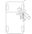
以下、実施形態に係る車両ドアにおける給電システムについて説明する。図1は給電システム30が車両10におけるドア20に組込まれた状態を示す図である。図1においてドア20が閉じられた状態が実線で示され、ドア20が開いた状態が2点鎖線で示されている。[Embodiment 1]
A power supply system for a vehicle door according to an embodiment will be described below. FIG. 1 is a diagram showing a state in which a
車両10は、車体12に、乗員が乗り降りするドア用開口14が設けられ、当該ドア用開口14がドア20によって開閉される。ここでは、ドア20の前部がヒンジ部を介して車体に連結されており、ドア20がヒンジ部を介してドア用開口14に対して開閉される例で説明する。また、ここでは、ドア20が運転席用ドアである例で説明するが,助手席用ドア、後部座席用ドアであってもよい。ドアは、荷物を出し入れするための開口を開閉可能に塞ぐ荷室用ドアであってもよい。ドアは、スライドドアであってもよい。 The
車体12には、電力供給源22及び非接触給電部24が組込まれている。電力供給源22は、補機用バッテリであってもよいし、発電機であってもよい。補機用バッテリは、車両に搭載された各種電気部品(制御機器、発光部、アクチュエータ等)に対して電力を供給するバッテリである。発電機は、車両に搭載された内燃機関による機械的エネルギーをから電気エネルギーに変換する機械である。車両10が電気自動車又はハイブリット自動車である場合には、電力供給源22は、動力用バッテリであってもよい。電力供給源22は、車体12においていずれの場所に設けられてもよい。 A
非接触給電部24は、電力供給源22からの電力を、後述する非接触受電部32に対して非接触で電力供給する部品である。非接触給電部24は、車体12のうちドア20の少なくとも一部に隣合って設けられる箇所に設けられる。 The non-contact
給電システム30は、非接触受電部32と、バッテリ34と、電気部品36とを備え、ドア20に組込まれる。 The
非接触受電部32は、非接触給電部24からの電力供給を非接触で受ける部品である。 The non-contact
バッテリ34は、充電可能な二次電池であり、非接触受電部32が受電した電力によって充電されるように、非接触受電部32に接続されている。 The
電気部品36は、ドア20に組込まれる電気部品である。電気部品36は、非接触受電部32が受電していない状態で、バッテリ34から給電されるようにバッテリ34に接続されている。ドア20に組込まれる電気部品としては、フットライト(footlight)、パワーウインドウ用モータ、ドアミラー用モータ、ドアロック用モータ等が想定される。フットライトは、ドア20に対して下方を照らすライトである。パワーウインドウ用モータは、ドアウインドウを開閉するためのモータである。ドアミラー用モータは、ドアミラーが向く方向を調整したり、ドアミラーを格納状態と非格納状態との間で姿勢変更したりするためのモータである。ドアロック用モータは、ドアをロック及びロック解除するためのモータである。バッテリ34に接続される電気部品は、ドア20が開いた状態で使用されるものが好ましく、例えば、フットライトを含むことが好ましい。
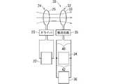
図2は給電システム30を示すブロック図である。同図に示すように、車体12には、電力供給源22及び非接触給電部24が設けられている。電力供給源22と非接触給電部24とは、ドライバ23を介して、電力供給源22からの電力を非接触給電部24に供給可能に接続されている。非接触給電部24は、給電用コイル25等を含んでいる。そして、ドライバ23による駆動によって、電力供給源22からの電力が非接触給電部24から非接触受電部32に向けてエネルギー(電磁波エネルギー等)として伝送される。 FIG. 2 is a block diagram showing the
非接触受電部32は、給電用コイル33等を含んでおり、上記給電用コイル25からのエネルギーを電力として受ける。 The non-contact
バッテリ34は、配線40を介して非接触受電部32に接続されている。配線40としては被覆電線等が用いられる。配線40には、整流回路35が介挿されており、非接触受電部32によって受電された交流波が直流波に整流される。非接触受電部が受電した電力によってバッテリ34が充電されるようになっている。
電気部品36は、配線42を介してバッテリ34に接続されている。配線42としては被覆電線等が用いられる。バッテリ34からの電力供給によって電気部品36が駆動される。ここでは、電気部品36は、配線42及び配線40を介して非接触受電部32にも接続されている。つまり、バッテリ34及び電気部品36は、非接触受電部32に対して並列接続されている。このため、非接触受電部32が受電した電力によっても電気部品36が駆動される。
非接触受電部32が受電している状態においては、非接触受電部32で受電された電力がバッテリ34及び電気部品36に供給される。非接触受電部32が受電していない状態においては、バッテリ34からの電力が電気部品36に供給される。 While the non-contact
上記非接触給電部24及び非接触受電部32は、ドア20を閉じた状態で、非接触による電力伝送を可能な位置に設けられている。例えば、非接触給電部24及び非接触受電部32は、ドア20を閉じた状態で、互いに対向する位置に配設される。図1では、車体12のうちドア用開口14の前寄りの位置に非接触給電部24が設けられている。また、ドア20のうち前寄りの位置に非接触受電部32が設けられている。 The non-contact
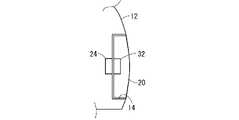
ドア20を閉じた状態では、図1及び図3に示すように、非接触給電部24と非接触受電部32とが対向配置され、非接触給電部24から非接触給電部24に向けて電力が伝送される状態となる。このため、ドア20を閉じた状態では、車体12に設けられた電力供給源22からの電力供給によってバッテリ34が充電される。また、車体12に設けられた電力供給源22からの電力供給によって電気部品36が動作する。 When the
ドア20を開いた状態では、図1及び図4に示すように、非接触給電部24に対して非接触給電部24が大きく離れ、非接触給電部24から非接触給電部24に向けた電力伝送が困難な状態又は不可な状態となる。このため、ドア20を開いた状態では、バッテリ34からの電力供給によって電気部品36が動作する。 When the
非接触給電部24及び非接触受電部32の配置例は上記例に限られない。例えば、非接触給電部24がドア用開口14のうち後ろ寄りの位置に非接触給電部24が設けられ、非接触受電部32がドア20のうち後ろ寄りの位置に配設されてもよい。 The arrangement example of the non-contact
なお、ドア20に設けられた全ての電気部品36が上記非接触給電部24及び非接触受電部32を介して車体12に設けられた電力供給源22に接続されている必要は無い。ドア20に設けられた複数の電気部品36のうちの一部が有線の電力線によって電力供給源22に接続されていてもよい。 It should be noted that not all the
このように構成された給電システム30によると、非接触受電部32が受電した電力によってバッテリ34が充電される。また、電気部品36は、少なくとも非接触受電部32が受電していない状態で、バッテリ34からの給電によって動作することができる。これにより、車体12とドア20との間で電力供給用の電線を少なくすることができる。例えば、ドア20に設けられた全ての電気部品36が上記非接触給電部24及び非接触受電部32を介して車体12に設けられた電力供給源22に接続されれば、車体12とドア20との間で電力供給を行うための電線を無くすることができる。 According to the
また、非接触受電部32が受電している状態で、非接触受電部32から電気部品36に電力供給がなされるため、バッテリ34を消費しないで、電気部品36に電力供給することができる。 Further, since power is supplied from the non-contact
[変形例]
上記実施形態を前提として各種変形例について説明する。[Modification]
Various modifications will be described on the premise of the above embodiment.
図5に示す第1変形例に係る給電システム130では、非接触受電部32と電気部品36とが配線140を介して接続されている。バッテリ34は、非接触受電部32に対して電気部品36と並列接続された状態となるように、配線142を介して上記配線140の途中に接続されている。配線142には、充電回路120が介挿されている。充電回路120によってバッテリ34を微弱電流で充電することができるため、バッテリ34を満充電状態に保ち易い。また、バッテリ34と電気部品36とは、配線144を介して接続されている。 In a
この給電システム130には、電気部品36への給電源を、非接触受電部32とバッテリ34とで切替える切替部110が設けられている。ここでは、切替部は、電流検出部112と切替回路114とを含む。電流検出部112は、配線140のうち非接触受電部32とバッテリ34との間の部分140aに介挿されており、当該配線部分140aを流れる電流を検出する。切替回路114は、リレー、半導体スイッチング素子等によって構成されており、配線140のうちバッテリ34と電気部品36との間の部分140b及び配線144とに介挿されている。切替回路114は、配線部分140bと配線144とを選択的に導通状態に切替える。換言すれば、切替回路114は、非接触受電部32から電気部品36に電力供給がなされる状態と、バッテリ34から電気部品36に電力供給がなされる状態とに選択的に切替える。そして、電流検出部112が配線部分140aに流れる電流を検出すると、切替回路114が配線部分140bを導通状態に切替え、非接触受電部32から電気部品36に電力供給がなされる状態となる。この状態では、非接触受電部32から充電回路120を介してバッテリ34に電力供給がなされるため、バッテリ34が充電される。また、電流検出部112が配線部分140aに流れる電流を検出しない状態になると、切替回路114が配線144を導通状態に切替え、バッテリ34から電気部品36に電力供給がなされる状態となる。 The
この例によると、非接触受電部32とバッテリとを切替えて、電気部品36に電力供給することができる。 According to this example, power can be supplied to the
なお、本変形例では、配線部分140aに電流がなされるか否か、即ち、非接触受電部32で受電されているか否かによって、給電源を、非接触受電部32とバッテリ34とで切替えているが、必ずしもその必要は無い。例えば、ドア20が閉じられ、非接触受電部32で受電している状態においても、バッテリ34の充電状態等に応じて、給電源を、非接触受電部32とバッテリ34とで切替えてもよい。 In this modified example, the power supply is switched between the non-contact
上記実施形態及び変形例では、ドア20の電気部品36への電力供給路を非接触給電化する例を説明した。電気部品36が電気制御ユニット(ECU)等によって制御される部品等である場合には、当該電気部品を制御するための信号線を無線化してもよい。 In the above-described embodiment and modified example, the example in which the power supply path to the
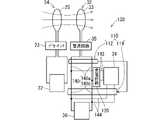
図6に示す第2変形例では、電気部品36に対応する電気部品236が車体12に設けられたECU17によって制御される部品であることを想定している。電気部品236は、上記実施形態で説明したような給電システムによって給電される。 In the second modified example shown in FIG. 6, it is assumed that an
上記EUC17には、無線通信部18が接続されている。無線通信部18は、無線通信回路18a及びアンテナ18bを含む。無線通信回路18a及びアンテナ18bは、車体12に設けられる。 A
また、電気部品236には、無線通信部237が接続されている。無線通信部237は、無線通信回路237a及びアンテナ237bを含む。無線通信回路237a及びアンテナ237bは、ドア20に設けられる。 A
そして、ECU17及び電気部品236は、無線通信部18及び無線通信部237を介して無線通信することができる。ECU17からの指令は、無線通信部18及び無線通信部237を介して電気部品236に無線送信され、電気部品236は当該指令に従って動作することができる。 The
本例によると、車体12とドア20との間において通信のための配線部材についても少なくできる。車体12とドア20との間において通信のための配線部材については、少なくとも一部が無線化されればよいが、全ての通信が無線化されれば、通信のための配線部材が無くなる。上記実施形態において、車体12とドア20との間において電力供給用の配線部材が全て無くされ、本変形例の適用によって、車体12とドア20との間において通信用の配線部材が全て無くされれば、車体12とドア20との間での配線部材が全て無くされる。車体12とドア20との間での配線部材が全て無くされれば、それらの間のグロメットも不要となる。 According to this example, wiring members for communication between the
なお、上記電力を非接触で供給するための電磁波エネルギー等に信号が重畳されて、ドア20側の電気部品236に伝送されてもよい。 It should be noted that a signal may be superimposed on the electromagnetic wave energy or the like for contactlessly supplying the electric power and transmitted to the
図7に係る第2変形例では、ドア20に電気部品としてECU336、ECU336により制御される電気部品337が設けられている。ECU336、電気部品337には、上記実施形態で説明したような給電システムによって給電される。 In the second modification shown in FIG. 7, the
また、ECU336には、無線通信部338が接続されている。無線通信部338は、無線通信回路338a及びアンテナ338bを含む。無線通信回路338a及びアンテナ338bは、ドア20に設けられる。 A
そして、車体12に設けられた電気部品としてのECU17とドア20に設けられたECU336とは、無線通信部18及び無線通信部338を介して無線通信することができる。ECU17からの指令は、無線通信部18及び無線通信部338を介してECU336に無線送信される。ECU336は、ECU17からの指令に応じて電気部品337を制御することができ、電気部品337はECU336からの指令に応じて動作する。 The
本例によっても、上記第2変形例と同様の効果を得ることができる。また、ECU336によって複数の電気部品337を制御することができる。 According to this example as well, the same effects as those of the second modified example can be obtained. Also, a plurality of
なお、上記各実施形態及び各変形例で説明した各構成は、相互に矛盾しない限り適宜組合わせることができる。例えば、上記第1変形例に対して、第2変形例、第3変形例が組合わされて、給電路及び通信路の無線化がなされてもよい。 In addition, each configuration described in each of the above-described embodiments and modifications can be appropriately combined as long as they do not contradict each other. For example, the first modification may be combined with the second modification and the third modification to make the power feeding path and the communication path wireless.
10 車両
12 車体
14 ドア用開口
17 ECU
18 無線通信部
18a 無線通信回路
18b アンテナ
20 ドア
22 電力供給源
23 ドライバ
24 非接触給電部
25 給電用コイル
30 給電システム
31 非接触受電部
32 非接触受電部
33 給電用コイル
34 バッテリ
35 整流回路
36 電気部品
40 配線
42 配線
110 切替部
112 電流検出部
114 切替回路
120 充電回路
130 給電システム
132 電流検出部
140 配線
140a 配線部分
140b 配線部分
140b 部分
142 配線
144 配線
236 電気部品
237 無線通信部
237a 無線通信回路
237b アンテナ
336 ECU
337 電気部品
338 無線通信部
338a 無線通信回路
338b アンテナ10
18
337
Claims (5)
Translated fromJapanese前記非接触受電部が受電した電力によって充電されるように、前記非接触受電部に接続されたバッテリと、
少なくとも前記非接触受電部が受電していない状態で、前記バッテリから給電されるように、前記バッテリに接続された電気部品と、
を備え、
車両ドアに設けられる、前記電気部品とは別の電気部品が有線の電力線によって車体に設けられた電力供給源に接続され、
前記非接触受電部が、前記車両ドアの室内向き部分に設けられて、前記車両ドアが閉められた状態で前記車体側に設けられた非接触給電部に対向する、車両ドアにおける給電システム。a contactless power receiving unit that receives contactless power supply;
a battery connected to the contactless power receiving unit so as to be charged by the power received by the contactless power receiving unit;
an electrical component connected to the battery so that power is supplied from the battery at least when the contactless power receiving unit is not receiving power;
with
an electrical component separate from the electrical component provided in the vehicle door is connected to a power supply source provided in the vehicle body by a wired power line;
A power feeding system for a vehicle door, wherein the non-contact power receiving unit is provided on a portion of the vehicle door facing the interior and faces the non-contact power feeding unit provided on the vehicle body side when the vehicle door is closed.
前記切替部は、前記非接触受電部からの電流を検出し、前記非接触受電部からの電流から検出されると、前記非接触受電部から前記電気部品に電力供給がなされ、かつ、前記バッテリから前記電気部品に電力供給がなされない状態とし、前記非接触受電部からの電流から検出されない状態になると、前記バッテリから前記電気部品に電力が供給される状態とする、車両ドアにおける給電システム。 The switching unit detects a current from the non-contact power receiving unit, and when the current from the non-contact power receiving unit is detected, the switching unit supplies power from the non-contact power receiving unit to the electric component, and a state in which no power is supplied to the electrical component from the contactless power receiving unit, and a state in which power is supplied from the battery to the electrical component when a state in which current from the non-contact power receiving unit is not detected is established.
Priority Applications (4)
| Application Number | Priority Date | Filing Date | Title |
|---|---|---|---|
| JP2019027389AJP7180439B2 (en) | 2019-02-19 | 2019-02-19 | Power supply system in vehicle door |
| PCT/JP2020/003292WO2020170744A1 (en) | 2019-02-19 | 2020-01-30 | Power feed system in vehicle door |
| CN202080014034.XACN113423612A (en) | 2019-02-19 | 2020-01-30 | Power supply system for vehicle door |
| US17/429,178US11738703B2 (en) | 2019-02-19 | 2020-01-30 | Power supply system in vehicle door |
Applications Claiming Priority (1)
| Application Number | Priority Date | Filing Date | Title |
|---|---|---|---|
| JP2019027389AJP7180439B2 (en) | 2019-02-19 | 2019-02-19 | Power supply system in vehicle door |
Publications (2)
| Publication Number | Publication Date |
|---|---|
| JP2020131895A JP2020131895A (en) | 2020-08-31 |
| JP7180439B2true JP7180439B2 (en) | 2022-11-30 |
Family
ID=72143777
Family Applications (1)
| Application Number | Title | Priority Date | Filing Date |
|---|---|---|---|
| JP2019027389AActiveJP7180439B2 (en) | 2019-02-19 | 2019-02-19 | Power supply system in vehicle door |
Country Status (4)
| Country | Link |
|---|---|
| US (1) | US11738703B2 (en) |
| JP (1) | JP7180439B2 (en) |
| CN (1) | CN113423612A (en) |
| WO (1) | WO2020170744A1 (en) |
Families Citing this family (1)
| Publication number | Priority date | Publication date | Assignee | Title |
|---|---|---|---|---|
| CN117677757A (en)* | 2021-10-15 | 2024-03-08 | 浙江吉利控股集团有限公司 | Sliding door electronic control mechanism, method and vehicle |
Citations (2)
| Publication number | Priority date | Publication date | Assignee | Title |
|---|---|---|---|---|
| JP2013112111A (en) | 2011-11-28 | 2013-06-10 | Sony Corp | In-vehicle reproduction system and display device |
| JP2016194841A (en) | 2015-04-01 | 2016-11-17 | リズム時計工業株式会社 | Usb fan device with charge function |
Family Cites Families (13)
| Publication number | Priority date | Publication date | Assignee | Title |
|---|---|---|---|---|
| JP3011007B2 (en)* | 1994-01-24 | 2000-02-21 | 住友電装株式会社 | Power supply structure to vehicle door |
| JPH11198742A (en) | 1998-01-14 | 1999-07-27 | Furukawa Electric Co Ltd:The | Routing structure of harness for car door |
| JP2000324725A (en)* | 1999-05-10 | 2000-11-24 | Yazaki Corp | Power supply |
| JP3851504B2 (en)* | 2000-11-16 | 2006-11-29 | 矢崎総業株式会社 | Automotive sliding door feeder |
| JP2002252937A (en)* | 2001-02-26 | 2002-09-06 | Yazaki Corp | Power supply device |
| US8186585B2 (en)* | 2007-07-24 | 2012-05-29 | Honeywell International Inc. | Integrated on-line door control system with standardized interfaces |
| JP2009120156A (en)* | 2007-11-19 | 2009-06-04 | Mitsubishi Cable Ind Ltd | Electric system for vehicle |
| US9744858B2 (en)* | 2008-09-27 | 2017-08-29 | Witricity Corporation | System for wireless energy distribution in a vehicle |
| US8975772B2 (en)* | 2011-03-16 | 2015-03-10 | Control Solutions LLC | Contactless power delivery system for power-assisted door and method |
| JP6114642B2 (en)* | 2013-06-13 | 2017-04-12 | アイシン精機株式会社 | Switchgear |
| JP6211376B2 (en)* | 2013-10-11 | 2017-10-11 | 矢崎総業株式会社 | Contactless power supply system |
| US10363820B2 (en)* | 2016-03-31 | 2019-07-30 | Ford Global Technologies, Llc | Wireless power transfer to a tailgate through capacitive couplers |
| KR20200111979A (en)* | 2019-03-20 | 2020-10-05 | 현대자동차주식회사 | Wireless power transfer systme for vehicle door glass |
- 2019
- 2019-02-19JPJP2019027389Apatent/JP7180439B2/enactiveActive
- 2020
- 2020-01-30CNCN202080014034.XApatent/CN113423612A/enactivePending
- 2020-01-30USUS17/429,178patent/US11738703B2/enactiveActive
- 2020-01-30WOPCT/JP2020/003292patent/WO2020170744A1/ennot_activeCeased
Patent Citations (2)
| Publication number | Priority date | Publication date | Assignee | Title |
|---|---|---|---|---|
| JP2013112111A (en) | 2011-11-28 | 2013-06-10 | Sony Corp | In-vehicle reproduction system and display device |
| JP2016194841A (en) | 2015-04-01 | 2016-11-17 | リズム時計工業株式会社 | Usb fan device with charge function |
Also Published As
| Publication number | Publication date |
|---|---|
| CN113423612A (en) | 2021-09-21 |
| WO2020170744A1 (en) | 2020-08-27 |
| US20220017030A1 (en) | 2022-01-20 |
| US11738703B2 (en) | 2023-08-29 |
| JP2020131895A (en) | 2020-08-31 |
Similar Documents
| Publication | Publication Date | Title |
|---|---|---|
| US20160347269A1 (en) | Vehicle wire harness | |
| US20130127180A1 (en) | Motor vehicle door | |
| US9021742B2 (en) | Opening and closing apparatus | |
| US20170210209A1 (en) | Vehicle electrical system | |
| KR20200133364A (en) | Control unit for car door | |
| JP6805158B2 (en) | Drive device for automobile closure elements | |
| US10053031B2 (en) | Wire harness | |
| US20020117896A1 (en) | Feeder apparatus | |
| EP2987675B1 (en) | Vehicle | |
| JP7180439B2 (en) | Power supply system in vehicle door | |
| JP2009144441A (en) | Door lock system for vehicle | |
| CN107406045A (en) | Power Distribution Devices for Automobiles | |
| US12273061B2 (en) | Apparatus and method for protecting vehicle door systems from back electromotive force (EMF) voltage | |
| JP2012060865A (en) | Communication system for vehicle | |
| CN109969122A (en) | locking device for vehicle | |
| US20180337556A1 (en) | Non-contact power transmission structure for sliding door | |
| CN115179898B (en) | Battery depletion electrolytic lock system and method without mechanical key vehicle type and automobile | |
| US20020117368A1 (en) | Feeder System | |
| US20020057071A1 (en) | Method of charging slide door-contained battery | |
| KR101380574B1 (en) | Door Control System For Vehicle | |
| CN114585791A (en) | Locking device for locking and/or unlocking a movable vehicle closing mechanism | |
| US20220388480A1 (en) | Method for Operating an Access System for a Vehicle, and Vehicle | |
| CN114599850A (en) | Door safety system, method for operating a door safety system and vehicle | |
| JP2009120019A (en) | In-vehicle power supply system | |
| JP2009166630A (en) | Electric system for vehicle |
Legal Events
| Date | Code | Title | Description |
|---|---|---|---|
| A621 | Written request for application examination | Free format text:JAPANESE INTERMEDIATE CODE: A621 Effective date:20210528 | |
| A131 | Notification of reasons for refusal | Free format text:JAPANESE INTERMEDIATE CODE: A131 Effective date:20220426 | |
| A521 | Request for written amendment filed | Free format text:JAPANESE INTERMEDIATE CODE: A523 Effective date:20220622 | |
| TRDD | Decision of grant or rejection written | ||
| A01 | Written decision to grant a patent or to grant a registration (utility model) | Free format text:JAPANESE INTERMEDIATE CODE: A01 Effective date:20221018 | |
| A61 | First payment of annual fees (during grant procedure) | Free format text:JAPANESE INTERMEDIATE CODE: A61 Effective date:20221031 | |
| R150 | Certificate of patent or registration of utility model | Ref document number:7180439 Country of ref document:JP Free format text:JAPANESE INTERMEDIATE CODE: R150 |