JP7179845B2 - Design for Remaining Minimum System Information (RMSI) Control Resource Set (CORESET) and Other System Information (OSI) CORESET - Google Patents
Design for Remaining Minimum System Information (RMSI) Control Resource Set (CORESET) and Other System Information (OSI) CORESETDownload PDFInfo
- Publication number
- JP7179845B2 JP7179845B2JP2020526876AJP2020526876AJP7179845B2JP 7179845 B2JP7179845 B2JP 7179845B2JP 2020526876 AJP2020526876 AJP 2020526876AJP 2020526876 AJP2020526876 AJP 2020526876AJP 7179845 B2JP7179845 B2JP 7179845B2
- Authority
- JP
- Japan
- Prior art keywords
- coreset
- ssb
- type
- search space
- common search
- Prior art date
- Legal status (The legal status is an assumption and is not a legal conclusion. Google has not performed a legal analysis and makes no representation as to the accuracy of the status listed.)
- Active
Links
Images


Classifications
- H—ELECTRICITY
- H04—ELECTRIC COMMUNICATION TECHNIQUE
- H04L—TRANSMISSION OF DIGITAL INFORMATION, e.g. TELEGRAPHIC COMMUNICATION
- H04L5/00—Arrangements affording multiple use of the transmission path
- H04L5/003—Arrangements for allocating sub-channels of the transmission path
- H04L5/0044—Allocation of payload; Allocation of data channels, e.g. PDSCH or PUSCH
- H—ELECTRICITY
- H04—ELECTRIC COMMUNICATION TECHNIQUE
- H04L—TRANSMISSION OF DIGITAL INFORMATION, e.g. TELEGRAPHIC COMMUNICATION
- H04L5/00—Arrangements affording multiple use of the transmission path
- H04L5/003—Arrangements for allocating sub-channels of the transmission path
- H04L5/0048—Allocation of pilot signals, i.e. of signals known to the receiver
- H—ELECTRICITY
- H04—ELECTRIC COMMUNICATION TECHNIQUE
- H04L—TRANSMISSION OF DIGITAL INFORMATION, e.g. TELEGRAPHIC COMMUNICATION
- H04L5/00—Arrangements affording multiple use of the transmission path
- H04L5/003—Arrangements for allocating sub-channels of the transmission path
- H04L5/0053—Allocation of signalling, i.e. of overhead other than pilot signals
- H—ELECTRICITY
- H04—ELECTRIC COMMUNICATION TECHNIQUE
- H04L—TRANSMISSION OF DIGITAL INFORMATION, e.g. TELEGRAPHIC COMMUNICATION
- H04L5/00—Arrangements affording multiple use of the transmission path
- H04L5/0091—Signalling for the administration of the divided path, e.g. signalling of configuration information
- H—ELECTRICITY
- H04—ELECTRIC COMMUNICATION TECHNIQUE
- H04W—WIRELESS COMMUNICATION NETWORKS
- H04W24/00—Supervisory, monitoring or testing arrangements
- H04W24/02—Arrangements for optimising operational condition
- H—ELECTRICITY
- H04—ELECTRIC COMMUNICATION TECHNIQUE
- H04W—WIRELESS COMMUNICATION NETWORKS
- H04W56/00—Synchronisation arrangements
- H04W56/001—Synchronization between nodes
- H—ELECTRICITY
- H04—ELECTRIC COMMUNICATION TECHNIQUE
- H04W—WIRELESS COMMUNICATION NETWORKS
- H04W72/00—Local resource management
- H04W72/04—Wireless resource allocation
- H04W72/044—Wireless resource allocation based on the type of the allocated resource
- H04W72/0453—Resources in frequency domain, e.g. a carrier in FDMA
- H—ELECTRICITY
- H04—ELECTRIC COMMUNICATION TECHNIQUE
- H04W—WIRELESS COMMUNICATION NETWORKS
- H04W72/00—Local resource management
- H04W72/12—Wireless traffic scheduling
- H04W72/1263—Mapping of traffic onto schedule, e.g. scheduled allocation or multiplexing of flows
- H—ELECTRICITY
- H04—ELECTRIC COMMUNICATION TECHNIQUE
- H04W—WIRELESS COMMUNICATION NETWORKS
- H04W72/00—Local resource management
- H04W72/12—Wireless traffic scheduling
- H04W72/1263—Mapping of traffic onto schedule, e.g. scheduled allocation or multiplexing of flows
- H04W72/1273—Mapping of traffic onto schedule, e.g. scheduled allocation or multiplexing of flows of downlink data flows
- H—ELECTRICITY
- H04—ELECTRIC COMMUNICATION TECHNIQUE
- H04W—WIRELESS COMMUNICATION NETWORKS
- H04W72/00—Local resource management
- H04W72/20—Control channels or signalling for resource management
- H04W72/23—Control channels or signalling for resource management in the downlink direction of a wireless link, i.e. towards a terminal
- H04W72/231—Control channels or signalling for resource management in the downlink direction of a wireless link, i.e. towards a terminal the control data signalling from the layers above the physical layer, e.g. RRC or MAC-CE signalling
- H—ELECTRICITY
- H04—ELECTRIC COMMUNICATION TECHNIQUE
- H04L—TRANSMISSION OF DIGITAL INFORMATION, e.g. TELEGRAPHIC COMMUNICATION
- H04L5/00—Arrangements affording multiple use of the transmission path
- H04L5/0001—Arrangements for dividing the transmission path
- H04L5/0003—Two-dimensional division
- H04L5/0005—Time-frequency
- H04L5/0007—Time-frequency the frequencies being orthogonal, e.g. OFDM(A) or DMT
Landscapes
- Engineering & Computer Science (AREA)
- Signal Processing (AREA)
- Computer Networks & Wireless Communication (AREA)
- Mobile Radio Communication Systems (AREA)
- Hardware Redundancy (AREA)
- Exchange Systems With Centralized Control (AREA)
Description
Translated fromJapanese[0001]本出願は、2017年11月17日に出願された「DESIGNS FOR REMAINING MINIMUM SYSTEM INFORMATION (RMSI) CONTROL RESOURCE SET (CORESET) AND OTHER SYSTEM INFORMATION (OSI) CORESET」と題する米国出願第62/588,245号の優先権および利益を主張する2018年10月25日に出願された米国出願第16/170,572号の優先権を主張する。上述の出願の全体が参照により本明細書に組み込まれる。 [0001] This application is subject to U.S. Application Serial No. 8/5, entitled "DESIGNS FOR REMAINING MINIMUM SYSTEM INFORMATION (RMSI) CONTROL RESOURCE SET (CORESET) AND OTHER SYSTEM INFORMATION (OSI) CORESET," filed November 17, 2017. No. 16/170,572, filed Oct. 25, 2018, which claims priority to and benefit from U.S. Application No. 16/170,572, filed Oct. 25, 2018. The entirety of the aforementioned application is incorporated herein by reference.
[0002]本開示の態様は、一般にワイヤレス通信システムに関し、より詳細には、残存最小システム情報(RMSI)制御リソースセット(CORESET)と他のシステム情報(OSI)CORESETとのための設計に関する。 [0002] Aspects of this disclosure relate generally to wireless communication systems, and more particularly to designs for minimum remaining system information (RMSI) control resource sets (CORESETs) and other system information (OSI) CORESETs.
[0003]ワイヤレス通信システムは、電話、ビデオ、データ、データ、メッセージング、ブロードキャストなど、様々な電気通信サービスを提供するために広く展開されている。システムは、利用可能なシステムリソース(たとえば、帯域幅および送信電力)を共有することによって複数のユーザとの通信をサポートすることが可能な多元接続技術を採用し得る。そのような多元接続システムの例には、第3世代パートナーシッププロジェクト(3GPP(登録商標))ロングタームエボリューション(LTE(登録商標))システム、LTEアドバンスト(LTE-A)システム、符号分割多元接続(CDMA)システム、時分割多元接続(TDMA)システム、周波数分割多元接続(FDMA)システム、直交周波数分割多元接続(OFDMA)システム、シングルキャリア周波数分割多元接続(SC-FDMA)システム、および時分割同期符号分割多元接続(TD-SCDMA)システムが含まれる。 [0003] Wireless communication systems are widely deployed to provide various telecommunication services such as telephone, video, data, messaging, broadcast, and so on. A system may employ multiple-access techniques that can support communication with multiple users by sharing available system resources (eg, bandwidth and transmit power). Examples of such multiple-access systems include 3rd Generation Partnership Project (3GPP) Long Term Evolution (LTE) systems, LTE Advanced (LTE-A) systems, Code Division Multiple Access (CDMA) ) systems, time division multiple access (TDMA) systems, frequency division multiple access (FDMA) systems, orthogonal frequency division multiple access (OFDMA) systems, single carrier frequency division multiple access (SC-FDMA) systems, and time division synchronous code division Multiple access (TD-SCDMA) systems are included.
[0004]いくつかの例では、ワイヤレス多元接続通信システムは、場合によってはユーザ機器(UE)として知られる、複数の通信デバイスのための通信を各々が同時にサポートすることができるいくつかの基地局(BS)を含み得る。LTEネットワークまたはLTE-Aネットワークでは、1つまたは複数の基地局のセットがeノードB(eNB)を定義することができる。他の例では(たとえば、NR、次世代ネットワークまたは5Gネットワークでは)、ワイヤレス多元接続通信システムは、いくつかの中央ユニット(CU)(たとえば、中央ノード(CN)、アクセスノードコントローラ(ANC)など)と通信しているいくつかの分散ユニット(DU)(たとえば、エッジユニット(EU)、エッジノード(EN)、無線ヘッド(RH)、スマート無線ヘッド(SRH)、送受信点(TRP)など)を含み得、中央ユニットと通信している1つまたは複数の分散ユニットのセットは、アクセスノード(たとえば、新無線基地局(NR BS)、新無線ノードB(NR NB)、ネットワークノード、5G NB、次世代ノードB(gNB)など)を定義し得る。BSまたはDUは、(たとえば、BSからまたはUEへの送信のために)ダウンリンクチャネル、および(たとえば、UEからBSまたはDUへの送信のために)アップリンクチャネル上でUEのセットと通信し得る。 [0004] In some examples, a wireless multiple-access communication system includes a number of base stations each capable of simultaneously supporting communication for multiple communication devices, sometimes known as user equipments (UEs). (BS). In an LTE or LTE-A network, a set of one or more base stations may define an eNodeB (eNB). In other examples (e.g., in NR, next-generation networks or 5G networks), a wireless multiple-access communication system comprises several central units (CUs) (e.g., central nodes (CN), access node controllers (ANC), etc.). including several distributed units (DUs) (e.g. edge units (EU), edge nodes (EN), radio heads (RH), smart radio heads (SRH), transmit/receive points (TRP), etc.) communicating with A set of one or more distributed units in communication with the central unit may be access nodes (e.g., new radio base stations (NR BS), new radio node Bs (NR NB), network nodes, 5G NB, next generation Node Bs (gNBs, etc.). A BS or DU communicates with a set of UEs over downlink channels (eg, for transmission from the BS or to the UE) and uplink channels (eg, for transmission from the UE to the BS or DU). obtain.
[0005]これらの多元接続技術は、異なるワイヤレスデバイスが都市、国家、地域、さらには地球規模で通信することを可能にする共通プロトコルを提供するために、様々な電気通信規格において採用されている。新生の電気通信規格の例は、新しい無線(NR)、たとえば、5G無線アクセスである。NRは、第3世代パートナーシッププロジェクト(3GPP)によって公表されたLTEモバイル規格の拡張のセットである。NRは、スペクトル効率を改善すること、コストを下げること、サービスを改善すること、新しいスペクトルを利用すること、ならびにダウンリンク(DL)上でおよびアップリンク(UL)上でサイクリックプレフィックス(CP)とともにOFDMAを使用して、他のオープン規格とより良く統合することによって、モバイルブロードバンドインターネットアクセスをより良くサポートし、ならびに、ビームフォーミング、多入力多出力(MIMO)アンテナ技術、およびキャリアアグリゲーションをサポートするように設計されている。 [0005] These multiple-access techniques have been adopted in various telecommunication standards to provide a common protocol that allows different wireless devices to communicate on a city, national, regional, and even global scale. . An example of an emerging telecommunications standard is New Radio (NR), eg 5G Radio Access. NR is a set of extensions to the LTE mobile standard promulgated by the 3rd Generation Partnership Project (3GPP). NR is used to improve spectral efficiency, lower costs, improve service, take advantage of new spectrum, and cyclic prefixes (CP) on the downlink (DL) and on the uplink (UL). better support mobile broadband Internet access by better integrating with other open standards, using OFDMA with is designed to
[0006]しかしながら、モバイルブロードバンドアクセスに対する需要が増加し続けるにつれて、NR技術のさらなる改善が必要である。好ましくは、これらの改善は、他の多元接続技術と、これらの技術を採用する電気通信規格とに適用可能であるべきである。 [0006] However, as the demand for mobile broadband access continues to increase, further improvements in NR technology are needed. Preferably, these improvements should be applicable to other multiple access technologies and telecommunications standards that employ these technologies.
[0007]本開示のシステム、方法、およびデバイスは、それぞれいくつかの態様を有し、それらのうちの単一の態様が単独で本開示の望ましい属性を担当するとは限らない。次に、以下の特許請求の範囲によって表される本開示の範囲を限定することなしに、いくつかの特徴について手短に説明する。この説明を考察すれば、特に「発明を実施するための形態」と題するセクションを読めば、本開示の特徴が、ワイヤレスネットワークにおけるアクセスポイントと局との間の改善された通信を含む利点をどのように提供するかが理解されよう。 [0007] The systems, methods, and devices of the disclosure each have several aspects, no single one of which is solely responsible for its desirable attributes. Without limiting the scope of the disclosure, which is represented by the following claims, some features will now be briefly described. Considering this description, and particularly reading the section entitled "Detailed Description," it will be seen how the features of the present disclosure provide advantages including improved communication between access points and stations in wireless networks. It will be appreciated how it is provided.
[0008]本開示のいくつかの態様は、一般に、残存最小システム情報(RMSI)制御リソースセット(CORESET)および他のシステム情報(OSI)CORESETのための設計に関する。 [0008] Certain aspects of this disclosure generally relate to designs for minimal remaining system information (RMSI) control resource sets (CORESETs) and other system information (OSI) CORESETs.
[0009]本開示のいくつかの態様は、ユーザ機器(UE)によるワイヤレス通信のための方法を提供する。本方法は、同期信号ブロック(SSB)によって搬送される物理ブロードキャストチャネル(PBCH)中でタイプ0物理ダウンリンク制御チャネル(PDCCH)共通探索空間制御リソースセット(CORESET)構成と物理リソースブロック(PRB)グリッドオフセットとを受信すること、タイプ0 PDCCH共通探索空間CORESET構成が、SSBのPRBの周波数ロケーションに対するタイプ0 PDCCH共通探索空間CORESETリソースブロック(PRB)の周波数ロケーションに関係する1つまたは複数のオフセットに対応する1つまたは複数のオフセット値を示すインジケーションを備える、を含む。本方法はまた、PRBグリッドオフセットを適用することによってタイプ0 PDCCH共通探索空間CORESETのPRBグリッドとSSBのPRBグリッドをアラインすることを含む。本方法はまた、UEによって記憶されたマッピングを使用して1つまたは複数のオフセット値にインジケーションをマッピングすることを含む。本方法はまた、1つまたは複数のオフセット値とSSB PRBの周波数ロケーションとに基づいてタイプ0 PDCCH共通探索空間CORESET PRBの周波数ロケーションを決定することによって含む。本方法はまた、タイプ0 PDCCH共通探索空間CORESET中でタイプ0 PDCCHを受信することを含む。 [0009] Certain aspects of the present disclosure provide a method for wireless communication by a user equipment (UE). The method provides a
[0010]本開示のいくつかの態様は、ユーザ機器(UE)によるワイヤレス通信のための方法を提供する。本開示のいくつかの態様は、ユーザ機器(UE)によるワイヤレス通信のための方法を提供する。本方法は、物理ダウンリンク共有チャネル(PDSCH)中でのタイプ0物理ダウンリンク制御チャネル(PDCCH)共通探索空間制御リソースセット(CORESET)の時間ロケーションを決定することを含む。本方法は、タイプ0 PDCCH共通探索空間CORESETの周波数ロケーションに基づいてPDSCH中でのタイプ0a物理ダウンリンク制御共通探索空間CORESETの時間ロケーションを決定することをさらに含む。本方法は、タイプ0a PDCCH共通探索空間CORESETを受信することをさらに含む。 [0010] Certain aspects of the present disclosure provide a method for wireless communication by a user equipment (UE). Certain aspects of the present disclosure provide a method for wireless communication by a user equipment (UE). The method includes determining the temporal location of a
[0011]態様は、概して、添付の図面を参照しながら本明細書で実質的に説明され、添付の図面によって示されるように、方法、装置、システム、コンピュータ可読媒体、および処理システムを含む。多数の他の態様が提供される。 [0011] Aspects generally include methods, apparatus, systems, computer-readable media, and processing systems substantially as described herein with reference to and as illustrated by the accompanying drawings. Numerous other aspects are provided.
[0012]上記のおよび関係する目的を達成するために、1つまたは複数の態様は、以下で十分に説明され、特に特許請求の範囲で指摘される特徴を備える。以下の説明および添付の図面に、1つまたは複数の態様のいくつかの例示的な特徴を詳細に記載する。ただし、これらの特徴は、様々な態様の原理が採用され得る様々な方法のほんのいくつかを示すものであり、この説明は、すべてのそのような態様およびそれらの均等物を含むものとする。 [0012] To the accomplishment of the foregoing and related ends, the one or more aspects comprise the features hereinafter fully described and particularly pointed out in the claims. The following description and the annexed drawings set forth in detail certain illustrative features of the one or more aspects. These features are indicative, however, of but a few of the various ways in which the principles of various aspects may be employed and this description is intended to include all such aspects and their equivalents.
[0013]本開示の上記で具陳された特徴が詳細に理解され得るように、添付の図面にその一部が示される態様を参照することによって、上記で手短に要約されたより具体的な説明が得られ得る。ただし、その説明は他の等しく有効な態様に通じ得るので、添付の図面は、本開示のいくつかの典型的な態様のみを示し、したがって、本開示の範囲を限定するものと見なされるべきではないことに留意されたい。
[0043]理解を容易にするために、可能な場合、各図に共通である同じ要素を指定するために同じ参照番号が使用されている。一態様において開示される要素が、特定の具陳なしに他の態様に対して有益に利用され得ることが企図される。 [0043] To facilitate understanding, where possible, the same reference numbers have been used to designate the same elements that are common to each figure. It is contemplated that elements disclosed in one aspect may be beneficially utilized on other aspects without specific recitation.
[0044]本開示の態様は、時間および周波数領域中での残存最小システム情報(RMSI)制御リソースセット(CORESET)と他のシステム情報(OSI)CORESETとのロケーションを決定するためのシステムおよび方法に関する。 [0044] Aspects of this disclosure relate to systems and methods for determining the location of Minimum Remaining System Information (RMSI) control resource sets (CORESETs) and other system information (OSI) CORESETs in the time and frequency domain. .
[0045]本開示の態様は、新しい無線(NR)(新しい無線アクセス技術または5G技術)のための装置、方法、処理システム、およびコンピュータ可読媒体を提供する。 [0045] Aspects of this disclosure provide apparatus, methods, processing systems, and computer-readable media for New Radio (NR) (new radio access technology or 5G technology).
[0046]NRは、拡張モバイルブロードバンド(eMBB)ターゲッティング広帯域幅(たとえば、80MHz超)、ミリメートル波(mmW)ターゲッティング高キャリア周波数(たとえば、27GHz以上)、マッシブMTC(mMTC)ターゲッティング非後方互換MTC技法、および/またはミッションクリティカルターゲッティング超高信頼低遅延通信(URLLC)などの、様々なワイヤレス通信サービスをサポートする。これらのサービスは、待ち時間および信頼性の要件を含み得る。これらのサービスは、それぞれのサービス品質(QoS)要件を満たすために、異なる送信時間間隔(TTI)をも有し得る。さらに、これらのサービスは、同じサブフレームにおいて共存し得る。 [0046] NR includes enhanced mobile broadband (eMBB) targeting wide bandwidth (e.g., >80 MHz), millimeter wave (mmW) targeting high carrier frequencies (e.g., >27 GHz), Massive MTC (mMTC) targeting non-backward compatible MTC techniques, and/or support various wireless communication services such as mission-critical targeting ultra-reliable low-latency communications (URLLC). These services may include latency and reliability requirements. These services may also have different transmission time intervals (TTI) to meet their respective quality of service (QoS) requirements. Moreover, these services can coexist in the same subframe.
[0047]いくつかの態様では、セル同期プロシージャは、UE(たとえば、図1に関して説明するようなUE120)によるセル探索および同期を容易にするためにSSB中で信号のセットをブロードキャストする基地局(たとえば、図1に関して説明するBS110)を伴い得る。SSBは、1次同期信号(PSS)と、2次同期信号(SSS)と、物理ブロードキャストチャネル(PBCH)とを含む。基地局によって送信されたSSBは、UEが、PSSに基づくシンボルタイミング、PSSおよびSSSに基づくセル識別情報、ならびにPBCH中で送られるシステム情報に基づく初期セルアクセスのために必要とされる他のパラメータなどのシステムタイミング情報を決定するのを助ける。 [0047] In some aspects, the cell synchronization procedure involves a base station (e.g.,
[0048]システム情報は、場合によっては、最小システム情報(MSI)ならびに他のシステム情報(OSI)を含み得る。場合によっては、MSIは、(LTEにおけるマスタ情報ブロック(MIB)と同様の)PBCHによって搬送される情報ならびに残存最小システム情報(RMSI)を含む。(MIBと同様の)PBCHによって搬送される情報は、セルから他の情報を取得するためにUEによって使用される情報である。RMSIは、セルへのUEのアクセスに関係する情報ならびにセル中のすべてのUEのための共通の無線リソース構成を含む。RMSIは、システム情報ブロック1(SIB1)と互換的に呼ばれることがあり、RMSI CORESETは、タイプ0物理ダウンリンク制御チャネル(PDCCH)共通探索空間CORESETと互換的に呼ばれることがあり、OSI CORESETは、タイプ0a物理ダウンリンク制御チャネル(PDCCH)共通探索空間CORESETと互換的に呼ばれることがある。RMSIは、上記で説明されたように、物理ダウンリンク共有チャネル(PDSCH)によって搬送される。UEは、PDCCH中で送られた情報に基づいてPDSCHのリソースを使用して通信するようにスケジュールされる。PDSCHはまた、OSIを搬送し得る。 [0048] System information may optionally include minimum system information (MSI) as well as other system information (OSI). In some cases, the MSI includes information carried by the PBCH (similar to the Master Information Block (MIB) in LTE) as well as the Minimum Remaining System Information (RMSI). The information carried by the PBCH (similar to the MIB) is the information used by the UE to obtain other information from the cell. The RMSI contains information related to UE access to the cell as well as a common radio resource configuration for all UEs in the cell. RMSI is sometimes interchangeably referred to as System Information Block 1 (SIB1), RMSI CORESET is sometimes interchangeably referred to as
[0049]RMSIをスケジュールするPDCCH(たとえば、タイプ0 PDCCH)は、SSBに関連するRMSI PDCCHモニタリングウィンドウ内の制御リソースセット(CORESET)中で送信され得る。場合によっては、RMSI CORESET(タイプ0 PDCH共通探索空間CORESET)は、RMSIを搬送するPDSCHをスケジュールするためのPDCCHがマッピングされるCORESETである。 [0049] The PDCCH that schedules the RMSI (eg,
[0050]本明細書で説明されるいくつかの実施形態は、UE(たとえば、UE120)などのワイヤレス通信デバイスが、周波数および時間領域中のSSB送信のロケーションに基づいて周波数および時間領域中でのRMSI CORESETとOSI CORESETとのロケーションを決定することを可能にすることを対象とする。RMSI CORESETおよびOSI CORESET周波数および時間リソースのロケーションを決定することにより、UEは、それぞれ、RMSI CORESETおよびOSI CORESETを受信することが可能になる。RMSI CORESETを受信することによって、UEは、どのUEがRMSIを搬送するPDSCHを受信し、復号することが可能であるのかに基づいてRMSI CORESET中でPDCCH(たとえば、タイプ0 PDCCH)を受信することが可能になる。また、UEは、周波数および時間領域中でのRMSI CORESETのロケーションに基づいて周波数および時間領域中でのOSI CORESETのロケーションを決定し得る。 [0050] Some embodiments described herein enable a wireless communication device, such as a UE (eg, UE 120), to determine the frequency and time domain based on the location of the SSB transmission in the frequency and time domain. It is intended to allow determining the location of the RMSI CORESET and the OSI CORESET. Determining the location of the RMSI CORESET and OSI CORESET frequency and time resources enables the UE to receive the RMSI CORESET and OSI CORESET, respectively. By receiving the RMSI CORESET, the UE may receive the PDCCH (e.g.,
[0051]以下の説明は、例を与えるものであり、特許請求の範囲に記載される範囲、適用性、または例を限定するものではない。本開示の範囲から逸脱することなく、説明される要素の機能および構成において変更が行われ得る。様々な例は、適宜に、様々な手順または構成要素を省略、置換、または追加し得る。たとえば、説明される方法は、説明される順序とは異なる順序で実施されてよく、様々なステップが追加、省略、または組み合わされ得る。また、いくつかの例に関して説明される特徴は、いくつかの他の例において組み合わされ得る。たとえば、本明細書に記載される態様を任意にいくつ使用しても、装置は実装され得、または方法は実施され得る。さらに、本開示の範囲は、本明細書に記載された開示の様々な態様に加えて、またはそれらの態様以外の他の構造、機能、または構造および機能を使用して実践される装置または方法を包含するものである。本明細書に開示される開示のいかなる態様も、請求項の1つまたは複数の要素によって具現化され得ることを理解されたい。「例示的」という単語は、「例、事例、または例示として機能すること」を意味するように本明細書で使用される。「例示的」として本明細書に記載されたいかなる態様も、必ずしも他の態様よりも好ましいまたは有利であると解釈されるべきではない。 [0051] The following description provides examples and does not limit the scope, applicability, or examples set forth in the claims. Changes may be made in the function and arrangement of elements described without departing from the scope of the disclosure. Various examples may omit, substitute, or add various procedures or components as appropriate. For example, methods described may be performed in a different order than that described, and various steps may be added, omitted, or combined. Also, features described with respect to some examples may be combined in some other examples. For example, an apparatus may be implemented or a method may be practiced using any number of the aspects set forth herein. Moreover, the scope of the present disclosure does not extend to any apparatus or method practiced using other structures, functions, or structures and functions in addition to or outside of the various aspects of the disclosure described herein. It includes It should be understood that any aspect of the disclosure disclosed herein may be embodied by one or more elements of a claim. The word "exemplary" is used herein to mean "serving as an example, instance, or illustration." Any aspect described herein as "exemplary" is not necessarily to be construed as preferred or advantageous over other aspects.
[0052]本明細書で説明される技法は、LTE、CDMA、TDMA、FDMA、OFDMA、SC-FDMAおよび他のネットワークなど、様々なワイヤレス通信ネットワークのために使用され得る。「ネットワーク」および「システム」という用語は、しばしば互換的に使用される。CDMAネットワークは、ユニバーサル地上波無線アクセス(UTRA)、cdma2000などの無線技術を実装し得る。UTRAは、広帯域CDMA(WCDMA(登録商標))とCDMAの他の変形形態とを含む。cdma2000は、IS-2000規格と、IS-95規格と、IS-856規格とを包含する。TDMAネットワークは、モバイル通信用グローバルシステム(GSM(登録商標))などの無線技術を実装することができる。OFDMAネットワークは、NR(たとえば、5G RA)、発展型UTRA(E-UTRA)、ウルトラモバイルブロードバンド(UMB)、IEEE802.11(Wi-Fi)、IEEE802.16(WiMAX)、IEEE802.20、Flash-OFDMAなどの無線技術を実装し得る。UTRAおよびE-UTRAは、ユニバーサルモバイルテレコミュニケーションシステム(UMTS)の一部である。NRは、5G技術フォーラム(5GTF)とともに開発中の新生のワイヤレス通信技術である。3GPPロングタームエボリューション(LTE)およびLTEアドバンスト(LTE-A)は、E-UTRAを使用するUMTSのリリースである。UTRA、E-UTRA、UMTS、LTE、LTE-A、およびGSMは、「第3世代パートナーシッププロジェクト」(3GPP)と称する団体からの文書に記載されている。cdma2000およびUMBは、「第3世代パートナーシッププロジェクト2」(3GPP2)と称する団体からの文書に記載されている。本明細書で説明される技法は、上記のワイヤレスネットワークおよび無線技術、ならびに他のワイヤレスネットワークおよび無線技術に使用され得る。明快のために、本明細書では、3Gおよび/または4Gのワイヤレス技術に一般に関連する用語を使用して態様が説明され得るが、本開示の態様は、NR技術を含む、5G以降など、他の世代ベースの通信システムにおいて適用され得る。
例示的なワイヤレス通信システム
[0053]図1は、本開示の態様が実行され得る例示的なワイヤレスネットワーク100を示す。たとえば、ユーザ機器120は、基地局120から物理ブロードキャストチャネル(PBCH)中で残存最小システム情報(RMSI)制御リソースセット(CORESET)構成を受信し得る。RMSI CORESET構成は、RMSI CORESET周波数リソースのロケーションを決定するためにUE120が使用し得るインジケーションを含み得る。さらに、UE120は、UE120がRMSI CORESET時間リソースのロケーションを決定することを可能にするRMSI CORESET時間リソースへのSSB時間リソースのマッピングを記憶し得る。[0052] The techniques described herein may be used for various wireless communication networks such as LTE, CDMA, TDMA, FDMA, OFDMA, SC-FDMA and other networks. The terms "network" and "system" are often used interchangeably. A CDMA network may implement a radio technology such as Universal Terrestrial Radio Access (UTRA), cdma2000, and so on. UTRA includes Wideband CDMA (WCDMA®) and other variants of CDMA. cdma2000 encompasses IS-2000, IS-95, and IS-856 standards. A TDMA network may implement a radio technology such as Global System for Mobile Communications (GSM). OFDMA networks include NR (eg, 5G RA), Evolved UTRA (E-UTRA), Ultra Mobile Broadband (UMB), IEEE 802.11 (Wi-Fi), IEEE 802.16 (WiMAX), IEEE 802.20, Flash- A radio technology such as OFDMA may be implemented. UTRA and E-UTRA are part of the Universal Mobile Telecommunications System (UMTS). NR is an emerging wireless communication technology under development with the 5G Technology Forum (5GTF). 3GPP Long Term Evolution (LTE) and LTE-Advanced (LTE-A) are releases of UMTS that use E-UTRA. UTRA, E-UTRA, UMTS, LTE, LTE-A, and GSM are described in documents from an organization named "3rd Generation Partnership Project" (3GPP). cdma2000 and UMB are described in documents from an organization named "3rd
Exemplary wireless communication system
[0053] FIG. 1 illustrates an
[0054]UEはまた、RMSI CORESETの時間および周波数ロケーションに基づいて他のシステム情報(OSI)CORESETの時間および周波数ロケーションを決定し得る。 [0054] The UE may also determine the time and frequency location of the Other System Information (OSI) CORESET based on the time and frequency location of the RMSI CORESET.
[0055]図1に示されているように、ワイヤレスネットワーク100は、いくつかのBS110と他のネットワークエンティティとを含み得る。BSはUEと通信する局であり得る。各BS110は、特定の地理的エリアに通信カバレージを提供し得る。3GPPでは、「セル」という用語は、この用語が使用されるコンテキストに応じて、ノードB(NB)のカバレージエリアおよび/またはこのカバレージエリアをサービスするノードBサブシステムを指すことができる。NRシステムでは、「セル」、BS、次世代ノードB(gNB)、ノードB、5G NB、アクセスポイント(AP)、NR BS、NR BS、または送受信(TRP)という用語は互換性があり得る。いくつかの例では、セルは必ずしも固定であるとは限らないことがあり、セルの地理的エリアは、モバイルBSのロケーションに従って移動することがある。いくつかの例では、BSは、任意の好適なトランスポートネットワークを使用して、直接物理接続、仮想ネットワークなど、様々なタイプのバックホールインターフェースを通して、互いに、および/あるいはワイヤレスネットワーク100中の1つまたは複数の他のBSまたはネットワークノード(図示せず)に相互接続され得る。 [0055] As shown in FIG. 1,
[0056]概して、任意の数のワイヤレスネットワークが所与の地理的エリア中に展開され得る。各ワイヤレスネットワークは、特定の無線アクセス技術(RAT)をサポートし得、1つまたは複数の周波数上で動作し得る。RATは、無線技術、エアインターフェースなどと呼ばれることもある。周波数は、キャリア、周波数チャネル、トーン、サブバンド、サブキャリアなどと呼ばれることもある。各周波数は、異なるRATのワイヤレスネットワーク間での干渉を回避するために、所与の地理的エリア中の単一のRATをサポートし得る。いくつかの場合には、NRまたは5G RATネットワークが展開され得る。 [0056] In general, any number of wireless networks may be deployed in a given geographic area. Each wireless network may support a particular radio access technology (RAT) and may operate on one or more frequencies. A RAT may also be referred to as a radio technology, air interface, or the like. A frequency may also be called a carrier, frequency channel, tone, subband, subcarrier, and so on. Each frequency may support a single RAT in a given geographical area to avoid interference between wireless networks of different RATs. In some cases, NR or 5G RAT networks may be deployed.
[0057]BSは、マクロセル、ピコセル、フェムトセル、および/または他のタイプのセルに通信カバレージを提供し得る。マクロセルは、比較的大きい地理的エリア(たとえば、半径数キロメートル)をカバーし得、サービスに加入しているUEによる無制限アクセスを可能にし得る。ピコセルは、比較的小さい地理的エリアをカバーし得、サービスに加入しているUEによる無制限アクセスを可能にし得る。フェムトセルは、比較的小さい地理的エリア(たとえば、自宅)をカバーし得、フェムトセルとの関連付けを有するUE(たとえば、限定加入者グループ(CSG)中のUE、自宅内のユーザのためのUEなど)による制限付きアクセスを可能にし得る。マクロセルのためのBSはマクロBSと呼ばれることがある。ピコセルのためのBSはピコBSと呼ばれることがある。フェムトセルのためのBSは、フェムトBSまたはホームBSと呼ばれることがある。図1に示されている例では、BS110a、110bおよび110cは、それぞれマクロセル102a、102bおよび102cのためのマクロBSであり得る。BS110xは、ピコセル102xのためのピコBSであり得る。BS110yおよび110zは、それぞれフェムトセル102yおよび102zのためのフェムトBSであり得る。BSは1つまたは複数の(たとえば、3つの)セルをサポートし得る。 [0057] A BS may provide communication coverage for macrocells, picocells, femtocells, and/or other types of cells. A macrocell may cover a relatively large geographic area (eg, several kilometers in radius) and may allow unrestricted access by UEs with service subscription. A pico-cell may cover a relatively small geographical area and may allow unrestricted access by UEs with service subscription. A femtocell may cover a relatively small geographical area (eg, a home) and UEs that have an association with the femtocell (eg, UEs in a closed subscriber group (CSG), UEs for users within the home). etc.). A BS for a macro cell is sometimes called a macro BS. A BS for pico cells is sometimes called a pico BS. A BS for a femtocell is sometimes called a Femto BS or Home BS. In the example shown in FIG. 1,
[0058]ワイヤレスネットワーク100はまた、中継局を含み得る。中継局は、上流局(たとえば、BSまたはUE)からデータおよび/または他の情報の送信を受信し、そのデータおよび/または他の情報の送信を下流局(たとえば、UEまたはBS)に送る局である。中継局はまた、他のUEに対する送信を中継するUEであり得る。図1に示されている例では、中継局110rは、BS110aとUE120rとの間の通信を容易にするために、BS110aおよびUE120rと通信し得る。中継局は、リレーBS、リレーなどと呼ばれることもある。 [0058]
[0059]ワイヤレスネットワーク100は、異なるタイプのBS、たとえば、マクロBS、ピコBS、フェムトBS、リレーなどを含む異種ネットワークであり得る。これらの異なるタイプのBSは、異なる送信電力レベル、異なるカバレージエリア、およびワイヤレスネットワーク100における干渉に対する異なる影響を有し得る。たとえば、マクロBSは、高い送信電力レベル(たとえば、20ワット)を有し得るが、ピコBS、フェムトBS、およびリレーは、より低い送信電力レベル(たとえば、1ワット)を有し得る。 [0059]
[0060]ワイヤレスネットワーク100は、同期動作または非同期動作をサポートし得る。同期動作の場合、BSは同様のフレームタイミングを有し得、異なるBSからの送信は近似的に時間的にアラインされ得る。非同期動作の場合、BSは異なるフレームタイミングを有し得、異なるBSからの送信は時間的にアラインされないことがある。本明細書で説明される技法は、同期動作と非同期動作の両方のために使用され得る。 [0060]
[0061]ネットワークコントローラ130は、BSのセットに結合し、これらのBSの協調および制御を行い得る。ネットワークコントローラ130は、バックホールを介してBS110と通信し得る。BS110はまた、たとえば、ワイヤレスバックホールまたはワイヤラインバックホールを介して直接または間接的に互いと通信し得る。 [0061] A
[0062]UE120(たとえば、120x、120yなど)はワイヤレスネットワーク100全体にわたって分散され得、各UEは固定または移動であり得る。UEは、移動局、端末、アクセス端末、加入者ユニット、局、顧客構内機器(CPE:Customer Premises Equipment)、セルラーフォン、スマートフォン、携帯情報端末(PDA)、ワイヤレスモデム、ワイヤレス通信デバイス、ハンドヘルドデバイス、ラップトップコンピュータ、コードレスフォン、ワイヤレスローカルループ(WLL)局、タブレット、カメラ、ゲームデバイス、ネットブック、スマートブック、ウルトラブック、医療デバイスまたは医療機器、生体センサー/生体デバイス、スマートウォッチ、スマートクロージング、スマートグラス、スマートリストバンド、スマートジュエリー(たとえば、スマートリング、スマートブレスレットなど)などのウェアラブルデバイス、エンターテインメントデバイス(たとえば、音楽デバイス、ビデオデバイス、衛星ラジオなど)、車両構成要素または車両センサー、スマートメーター/スマートセンサー、工業用製造機器、全地球測位システムデバイス、あるいはワイヤレス媒体またはワイヤード媒体を介して通信するように構成された任意の他の好適なデバイスと呼ばれることもある。いくつかのUEは、発展型もしくはマシンタイプ通信(MTC)デバイスまたは発展型MTC(eMTC)デバイスと見なされ得る。MTC UEおよびeMTC UEは、たとえば、BS、別のデバイス(たとえば、リモートデバイス)、または何らかの他のエンティティと通信し得る、ロボット、ドローン、リモートデバイス、センサー、メーター、モニタ、ロケーションタグなどを含む。ワイヤレスノードは、たとえば、ワイヤードまたはワイヤレス通信リンクを介した、ネットワーク(たとえば、インターネットまたはセルラーネットワークなど、ワイドエリアネットワーク)のための、またはネットワークへの接続性を提供し得る。いくつかのUEは、モノのインターネット(IoT)デバイスまたは狭帯域IoT(NB-IoT)デバイスと見なされ得る。 [0062] UEs 120 (eg, 120x, 120y, etc.) may be dispersed throughout
[0063]図1では、両矢印付きの実線は、ダウンリンクおよび/またはアップリンク上での、UEと、そのUEをサービスするように指定されたBSであるサービングBSとの間の所望の送信を示す。両矢印付きの破線は、UEとBSとの間の干渉送信を示す。 [0063] In FIG. 1, the solid line with double arrows indicates the desired transmission between the UE and the serving BS, which is the BS designated to serve the UE, on the downlink and/or uplink. indicate. A dashed line with double arrows indicates an interfering transmission between a UE and a BS.
[0064]いくつかのワイヤレスネットワーク(たとえば、LTE)は、ダウンリンク上では直交周波数分割多重(OFDM)を利用し、アップリンク上ではシングルキャリア周波数分割多重(SC-FDM)を利用する。OFDMおよびSC-FDMは、システム帯域幅を、一般にトーン、ビンなどとも呼ばれる複数(K)個の直交サブキャリアに区分する。各サブキャリアはデータで変調され得る。概して、変調シンボルは、OFDMでは周波数領域で、SC-FDMでは時間領域で送られる。隣接するサブキャリア間の間隔は固定であり得、サブキャリアの総数(K)はシステム帯域幅に依存し得る。たとえば、サブキャリアの間隔は15kHzであってよく、(物理リソースブロック(PRB)と呼ばれる)最小リソース割振りは、12個のサブキャリア(または180kHz)であり得る。したがって、公称FFTサイズは、1.25、2.5、5、10または20メガヘルツ(MHz)のシステム帯域幅に対してそれぞれ128、256、512、1024または2048に等しくなり得る。システム帯域幅はまた、サブバンドに区分され得る。たとえば、サブバンドは1.08MHz(すなわち、6つのPRB)をカバーし得、1.25、2.5、5、10または20MHzのシステム帯域幅に対してそれぞれ1、2、4、8または16個のサブバンドがあり得る。 [0064] Some wireless networks (eg, LTE) utilize orthogonal frequency division multiplexing (OFDM) on the downlink and single-carrier frequency division multiplexing (SC-FDM) on the uplink. OFDM and SC-FDM partition the system bandwidth into multiple (K) orthogonal subcarriers, which are also commonly called tones, bins, and so on. Each subcarrier may be modulated with data. In general, modulation symbols are sent in the frequency domain with OFDM and in the time domain with SC-FDM. The spacing between adjacent subcarriers may be fixed, and the total number of subcarriers (K) may depend on system bandwidth. For example, the subcarrier spacing may be 15 kHz, and the minimum resource allocation (called physical resource blocks (PRBs)) may be 12 subcarriers (or 180 kHz). Therefore, the nominal FFT size can be equal to 128, 256, 512, 1024 or 2048 for system bandwidths of 1.25, 2.5, 5, 10 or 20 megahertz (MHz) respectively. The system bandwidth may also be partitioned into subbands. For example, a subband may cover 1.08 MHz (i.e., 6 PRBs) and 1, 2, 4, 8 or 16 for system bandwidths of 1.25, 2.5, 5, 10 or 20 MHz, respectively. There can be subbands.
[0065]本明細書で説明される例の態様は、LTE技術に関連付けられ得るが、本開示の態様は、NRなど、他のワイヤレス通信システムとともに適用可能であり得る。 [0065] Although aspects of the examples described herein may relate to LTE technology, aspects of the disclosure may be applicable with other wireless communication systems, such as NR.
[0066]NRは、アップリンクおよびダウンリンク上でCPとともにOFDMを利用し、TDDを使用する半二重動作のサポートを含み得る。100MHzの単一のコンポーネントキャリア帯域幅がサポートされ得る。NRリソースブロックは、0.1msの持続時間にわたる75kHzのサブキャリア帯域幅をもつ12個のサブキャリアにわたり得る。各無線フレームは、各々が5つのサブフレームからなる2つの1/2フレームからなり、10msの長さをもち得る。したがって、各サブフレームは、1msの長さを有し得る。各サブフレームは、データ送信のためのリンク方向(すなわち、DLまたはUL)を示し得、各サブフレームのためのリンク方向は、動的に切り替えられ得る。各サブフレームは、DL/ULデータならびにDL/UL制御データを含み得る。NRのためのULおよびDLサブフレームは、図6および図7に関して以下でより詳細に説明する通りであり得る。ビームフォーミングがサポートされ得、ビーム方向が動的に構成され得る。プリコーディングを用いたMIMO送信も、サポートされ得る。DLにおけるMIMO構成は、最高8つのストリームおよびUEごとに最高2つのストリームのマルチレイヤDL送信を用いて、最高8つの送信アンテナをサポートし得る。UEごとに最高2つのストリームをもつマルチレイヤ送信が、サポートされ得る。複数のセルのアグリゲーションが、最高8つのサービングセルを用いてサポートされ得る。代替的に、NRは、OFDMベース以外の異なるエアインターフェースをサポートし得る。NRネットワークは、CUおよび/またはDUのような、エンティティを含み得る。 [0066] NR utilizes OFDM with CP on the uplink and downlink and may include support for half-duplex operation using TDD. A single component carrier bandwidth of 100 MHz may be supported. An NR resource block may span 12 subcarriers with a subcarrier bandwidth of 75 kHz over a duration of 0.1 ms. Each radio frame may consist of two half-frames of five subframes each and have a length of 10 ms. Therefore, each subframe may have a length of 1 ms. Each subframe may indicate a link direction (ie, DL or UL) for data transmission, and the link direction for each subframe may be dynamically switched. Each subframe may contain DL/UL data as well as DL/UL control data. UL and DL subframes for NR may be as described in more detail below with respect to FIGS. Beamforming may be supported and beam directions may be dynamically configured. MIMO transmission with precoding may also be supported. A MIMO configuration in DL may support up to 8 transmit antennas with multi-layer DL transmission of up to 8 streams and up to 2 streams per UE. Multi-layer transmission with up to two streams per UE may be supported. Aggregation of multiple cells may be supported with up to eight serving cells. Alternatively, NR may support different air interfaces other than OFDM-based. An NR network may include entities such as CUs and/or DUs.
[0067]LTEでは、基本送信時間間隔(TTI)またはパケット持続時間は、1つのサブフレームである。NRでは、サブフレームは依然として1msであるが、基本TTIはスロットと呼ばれる。サブフレームは、トーン間隔(たとえば、15、30、60、120、240..kHz)に応じて可変数のスロット(たとえば、1、2、4、8、16、...スロット)を含んでいる。 [0067] In LTE, the basic transmission time interval (TTI) or packet duration is one subframe. In NR, a subframe is still 1ms, but the basic TTI is called a slot. A subframe contains a variable number of slots (eg, 1, 2, 4, 8, 16, ... slots) depending on the tone spacing (eg, 15, 30, 60, 120, 240.. kHz). there is
[0068]ビームフォーミングは、概して、(ビームフォーミングを送信するための)個々のアンテナ信号の大きさおよび位相を適宜に重み付けすることによって波面の方向を制御するための複数のアンテナの使用を指す。ビームフォーミングは、拡張カバレージ中に生じ得、アレイ中の各アンテナが、操作された信号に寄与し得るので、アレイ利得(またはビームフォーミング利得)が達成される。ビームフォーミングを受信することは、波面が到着することになる方向(到着方向またはDoA)を決定することを可能にする。干渉信号の方向にビームパターンヌルを適用することによって選択された干渉信号を抑制することも可能であり得る。適応ビームフォーミングは、移動する受信機にビームフォーミングを連続的に適用する技法を指す。 [0068] Beamforming generally refers to the use of multiple antennas to control the direction of the wavefront by appropriately weighting the magnitude and phase of the individual antenna signals (for transmitting beamforming). Beamforming may occur during extended coverage, and each antenna in the array may contribute to the steered signal, thus achieving array gain (or beamforming gain). Receiving beamforming makes it possible to determine the direction in which the wavefront will arrive (Direction of Arrival or DoA). It may also be possible to suppress selected interfering signals by applying beam pattern nulls in the direction of the interfering signals. Adaptive beamforming refers to techniques that continuously apply beamforming to moving receivers.
[0069]いくつかの例では、エアインターフェースへのアクセスがスケジュールされ得、スケジューリングエンティティ(たとえば、BS)が、それのサービスエリアまたはセル内の一部または全部のデバイスおよび機器の間での通信のためのリソースを割り振る。本開示内では、以下でさらに説明されるように、スケジューリングエンティティは、1つまたは複数の従属エンティティのためのリソースをスケジュールすること、割り当てること、再構成すること、および解放することを担当し得る。すなわち、スケジュールされた通信のために、従属エンティティは、スケジューリングエンティティによって割り振られたリソースを利用する。BSは、スケジューリングエンティティとして機能し得る唯一のエンティティではない。すなわち、いくつかの例では、UEが、1つまたは複数の従属エンティティ(たとえば、1つまたは複数の他のUE)のためのリソースをスケジュールする、スケジューリングエンティティとして機能し得る。この例では、UEは、スケジューリングエンティティとして機能しており、他のUEは、ワイヤレス通信のためにUEによってスケジュールされたリソースを利用する。UEは、ピアツーピア(P2P)ネットワークにおいて、および/またはメッシュネットワークにおいてスケジューリングエンティティとして機能し得る。メッシュネットワーク例では、UEは、スケジューリングエンティティと通信することに加えて互いに直接通信し得る。 [0069] In some examples, access to the air interface may be scheduled, and a scheduling entity (eg, a BS) controls communication between some or all devices and equipment within its coverage area or cell. Allocate resources for Within this disclosure, a scheduling entity may be responsible for scheduling, allocating, reconfiguring, and releasing resources for one or more dependent entities, as further described below. . That is, for scheduled communications, dependent entities utilize resources allocated by the scheduling entity. A BS is not the only entity that can act as a scheduling entity. That is, in some examples, a UE may act as a scheduling entity that schedules resources for one or more dependent entities (eg, one or more other UEs). In this example, the UE is acting as a scheduling entity and other UEs utilize resources scheduled by the UE for wireless communication. A UE may act as a scheduling entity in a peer-to-peer (P2P) network and/or in a mesh network. In a mesh network example, UEs may communicate directly with each other in addition to communicating with the scheduling entity.
[0070]したがって、時間周波数リソースへのスケジュールされたアクセスを伴い、セルラー構成と、P2P構成と、メッシュ構成とを有するワイヤレス通信ネットワークでは、スケジューリングエンティティおよび1つまたは複数の従属エンティティは、スケジュールされたリソースを利用して通信し得る。 [0070] Thus, in a wireless communication network with cellular, P2P and mesh configurations, with scheduled access to time-frequency resources, the scheduling entity and one or more subordinate entities are Communicate using resources.
[0071]図2は、図1に示されているワイヤレス通信システムにおいて実装され得る、分散型無線アクセスネットワーク(RAN)200の例示的な論理アーキテクチャを示す。5Gアクセスノード206は、アクセスノードコントローラ(ANC)202を含み得る。ANC202は、分散型RAN200の中央ユニット(CU)であり得る。次世代コアネットワーク(NG-CN)204へのバックホールインターフェースは、ANC202において終端し得る。隣接する次世代アクセスノード(NG-AN)210へのバックホールインターフェースは、ANC202において終端し得る。ANC202は、(BS、NR BS、ノードB、gNB、5G NB、AP、または何らかの他の用語で呼ばれることもある)1つまたは複数のTRP208を含み得る。上記で説明されたように、TRPは、「セル」と互換的に使用され得る。 [0071] FIG. 2 shows an exemplary logical architecture of a distributed radio access network (RAN) 200 that may be implemented in the wireless communication system shown in FIG. A
[0072]TRP208はDUであり得る。TRP208は、1つのANC(ANC202)または(示されていない)2つ以上のANCに接続され得る。たとえば、RAN共有、サービスとしての無線(RaaS:radio as a service)、およびサービス固有AND展開(service specific AND deployment)の場合、TRPは2つ以上のANCに接続され得る。TRPは1つまたは複数のアンテナポートを含み得る。TRPは、UEにトラフィックを、個々にサービスする(たとえば、動的選択)か、または一緒にサービスする(たとえば、ジョイント送信)ように構成され得る。 [0072]
[0073]論理アーキテクチャは、異なる展開タイプにわたるフロントホーリングソリューションをサポートし得る。たとえば、論理アーキテクチャは、送信ネットワーク能力(たとえば、帯域幅、レイテンシ、および/またはジッタ)に基づき得る。論理アーキテクチャは、LTEと特徴および/または構成要素を共有し得る。NG-AN210は、NRとのデュアル接続性をサポートし得る。NG-AN210は、LTEおよびNRについて共通フロントホールを共有し得る。 [0073] The logical architecture may support fronthauling solutions across different deployment types. For example, the logical architecture can be based on transmission network capabilities (eg, bandwidth, latency, and/or jitter). The logical architecture may share features and/or components with LTE. NG-
[0074]論理アーキテクチャは、TRP208間の協働を可能にし得る。たとえば、協働は、ANC202を介してTRP内でおよび/またはTRPにわたってプリセットされ得る。インターTRPインターフェースが使用されないことがある。 [0074] A logical architecture may enable cooperation between the TRPs 208 . For example, cooperation may be preset within and/or across TRPs via
[0075]論理アーキテクチャは、分割論理機能の動的構成をサポートし得る。図5を参照しながらより詳細に説明するように、無線リソース制御(RRC)レイヤ、パケットデータコンバージェンスプロトコル(PDCP)レイヤ、無線リンク制御(RLC)レイヤ、媒体アクセス制御(MAC)レイヤ、および物理(PHY)レイヤが、DUまたはCU(たとえば、それぞれTRPまたはANC)に適応的に配置され得る。BSは、中央ユニット(CU)(たとえば、ANC202)および/または1つもしくは複数の分散型ユニット(たとえば、1つまたは複数のTRP208)を含み得る。 [0075] The logic architecture may support dynamic configuration of split logic functions. As will be described in more detail with reference to FIG. 5, the radio resource control (RRC) layer, the packet data convergence protocol (PDCP) layer, the radio link control (RLC) layer, the medium access control (MAC) layer, and the physical ( PHY) layer may be adaptively placed in the DU or CU (eg, TRP or ANC, respectively). A BS may include a central unit (CU) (eg, ANC 202) and/or one or more distributed units (eg, one or more TRPs 208).
[0076]図3は、本開示の態様による、分散型RAN300の例示的な物理アーキテクチャを示す。集中型コアネットワークユニット(C-CU)302は、コアネットワーク機能をホストし得る。C-CU302は中央に展開され得る。C-CU機能性は、ピーク容量を扱おうとして、(たとえば、高度ワイヤレスサービス(AWS)に)オフロードされ得る。 [0076] FIG. 3 illustrates an exemplary physical architecture of a distributed
[0077]集中型RANユニット(C-RU)304は、1つまたは複数のANC機能をホストし得る。C-RU304は、ローカルにコアネットワーク機能をホストし得る。C-RU304は分散型展開を有し得る。C-RU304はネットワークエッジに近接し得る。 [0077] A centralized RAN unit (C-RU) 304 may host one or more ANC functions. C-
[0078]DU306は、1つまたは複数のTRP(エッジノード(EN)、エッジユニット(EU)、無線ヘッド(RH)、スマート無線ヘッド(SRH)など)をホストし得る。DU306は、無線周波数(RF)機能をもつネットワークのエッジに位置し得る。 [0078]
[0079]図4に、本開示の態様を実装するために使用され得る、図1に示されているBS110およびUE120の例示的な構成要素を示す。 [0079] FIG. 4 illustrates exemplary components of
[0080]上記で説明されたように、BS110はgNB、TRPなどであり得る。BS110およびUE120の1つまたは複数の構成要素は、本開示の態様を実施するために使用され得る。たとえば、UE120のアンテナ452、Tx/Rx222、プロセッサ466、458、464、および/またはコントローラ/プロセッサ480、ならびに/あるいはBS110のアンテナ434、プロセッサ460、420、438、および/またはコントローラ/プロセッサ440は、本明細書で説明され、図11、図17、および図20を参照しながら図示される動作を実行するために使用され得る。 [0080] As explained above, the
[0081]図4は、図1中のBSのうちの1つであり得るBS110および図1中のUEのうちの1つであり得るUE120の設計のブロック図を示す。制限付き関連付けシナリオの場合、BS110は図1中のマクロBS110cであり得、UE120はUE120yであり得る。BS110はまた、何らかの他のタイプのBSであり得る。BS110はアンテナ434a~434tを装備し得、UE120はアンテナ452a~452rを装備し得る。 [0081] FIG. 4 shows a block diagram of a design of
[0082]BS110において、送信プロセッサ420が、データソース412からデータを受信し、コントローラ/プロセッサ440から制御情報を受信し得る。制御情報は、物理ブロードキャストチャネル(PBCH)、物理制御フォーマットインジケータチャネル(PCFICH)、物理ハイブリッドARQインジケータチャネル(PHICH)、物理ダウンリンク制御チャネル(PDCCH)などのためのものであり得る。データは物理ダウンリンク共有チャネル(PDSCH)などのためのものであり得る。プロセッサ420は、それぞれデータシンボルおよび制御シンボルを取得するために、データおよび制御情報を処理(たとえば、符号化およびシンボルマッピング)し得る。プロセッサ420はまた、たとえば、1次同期信号(PSS)、1次同期信号(SSS)、およびセル固有基準信号のための基準シンボルを生成し得る。送信(TX)多入力多出力(MIMO)プロセッサ430が、適用可能な場合、データシンボル、制御シンボル、および/または基準シンボルに対して空間処理(たとえば、プリコーディング)を実行し得、出力シンボルストリームを変調器(MOD)432a~432tに与え得る。各変調器432は、(たとえば、OFDMなどのための)それぞれの出力シンボルストリームを処理して、出力サンプルストリームを取得し得る。各変調器432は、出力サンプルストリームをさらに処理(たとえば、アナログへの変換、増幅、フィルタ処理、およびアップコンバート)して、ダウンリンク信号を取得し得る。変調器432a~432tからのダウンリンク信号は、それぞれアンテナ434a~434tを介して送信され得る。以下でより詳細に説明するように、場合によっては、同期、基準信号、およびブロードキャスト信号は、フレキシブルな帯域幅割振りを有し得、DCトーンを中心としないことがある。 [0082] At
[0083]UE120において、アンテナ452a~452rは、基地局110からダウンリンク信号を受信し得、受信信号をそれぞれ復調器(DEMOD)454a~454rに与え得る。各復調器454は、入力サンプルを取得するために、それぞれの受信信号を調整(たとえば、フィルタ処理、増幅、ダウンコンバート、およびデジタル化)し得る。各復調器454は、さらに、受信シンボルを取得するために、(たとえば、OFDMなどのための)入力サンプルを処理し得る。MIMO検出器456は、すべての復調器454a~454rから受信シンボルを取得し、適用可能な場合は受信シンボルに対してMIMO検出を実施し、検出されたシンボルを与え得る。受信プロセッサ458は、検出シンボルを処理(たとえば、復調、デインターリーブ、および復号)し、UE120の復号されたデータをデータシンク460に与え、復号された制御情報をコントローラ/プロセッサ480に与え得る。 [0083] At
[0084]アップリンク上では、UE120において、送信プロセッサ464が、データソース462から(たとえば、物理アップリンク共有チャネル(PUSCH)のための)データを受信し、処理し得、コントローラ/プロセッサ480から(たとえば、物理アップリンク制御チャネル(PUCCH)のための)制御情報を受信し、処理し得る。送信プロセッサ464はまた、基準信号のための基準シンボルを生成し得る。送信プロセッサ464からのシンボルは、適用可能な場合はTX MIMOプロセッサ466によってプリコーディングされ、さらに(たとえば、SC-FDMなどのために)変調器454a~454rによって処理され、BS110に送信され得る。BS110において、UE120からのアップリンク信号は、アンテナ434によって受信され、変調器432によって処理され、適用可能な場合はMIMO検出器436によって検出され、UE120によって送られた復号されたデータおよび制御情報を取得するために、受信プロセッサ438によってさらに処理され得る。受信プロセッサ438は、復号されたデータをデータシンク439に提供し、復号された制御情報をコントローラ/プロセッサ440に提供し得る。 [0084] On the uplink, in
[0085]コントローラ/プロセッサ440および480は、それぞれBS110における動作およびUE120における動作を指示し得る。BS110におけるプロセッサ440および/または他のプロセッサおよびモジュールは、本明細書で説明する技法のための実行プロセスを実行するか、または指示し得る。UE120におけるプロセッサ480ならびに/または他のプロセッサおよびモジュールは、たとえば、図11、図17、および図20に示されている機能ブロック、および/または本明細書で説明される技法のための他のプロセスを実行するか、またはその実行を指示し得る。メモリ442および482は、それぞれBS110およびUE120のためのデータおよびプログラムコードを記憶し得る。スケジューラ444は、ダウンリンクおよび/またはアップリンク上でのデータ送信のためにUEをスケジュールし得る。 [0085] Controllers/
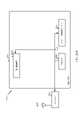
[0086]図5に、本開示の態様による、通信プロトコルスタックを実装するための例を示す図500を示す。図示されている通信プロトコルスタックは、5Gシステム(たとえば、アップリンクベースのモビリティをサポートするシステム)において動作するデバイスによって実装され得る。図500は、無線リソース制御(RRC)レイヤ510と、パケットデータコンバージェンスプロトコル(PDCP)レイヤ515と、無線リンク制御(RLC)レイヤ520と、媒体アクセス制御(MAC)レイヤ525と、物理(PHY)レイヤ530とを含む通信プロトコルスタックを示す。様々な例では、プロトコルスタックのレイヤは、ソフトウェアの別個のモジュール、プロセッサまたはASICの部分、通信リンクによって接続されたコロケートされていないデバイスの部分、あるいはそれらの様々な組合せとして実装され得る。コロケートされた実装形態およびコロケートされていない実装形態は、たとえば、ネットワークアクセスデバイス(たとえば、AN、CU、および/またはDU)またはUEのためのプロトコルスタックにおいて使用され得る。 [0086] FIG. 5 shows a diagram 500 illustrating an example for implementing a communication protocol stack, according to aspects of the present disclosure. The illustrated communication protocol stacks may be implemented by devices operating in 5G systems (eg, systems supporting uplink-based mobility). Diagram 500 shows a radio resource control (RRC)
[0087]第1のオプション505-aは、プロトコルスタックの実装が、集中型ネットワークアクセスデバイス(たとえば、図2中のANC202)と分散型ネットワークアクセスデバイス(たとえば、図2中のDU208)との間で分割された、プロトコルスタックの分割された実装形態を示す。第1のオプション505-aでは、RRCレイヤ510およびPDCPレイヤ515は、中央ユニットによって実装され得、RLCレイヤ520、MACレイヤ525、およびPHYレイヤ530は、DUによって実装され得る。様々な例では、CUおよびDUは、コロケートされることもコロケートされないこともある。第1のオプション505-aは、マクロセル、マイクロセル、またはピコセル展開において有用であり得る。 [0087] A first option 505-a is that the protocol stack implementation is between a centralized network access device (eg,
[0088]第2のオプション505-bは、プロトコルスタックが、単一のネットワークアクセスデバイス(たとえば、アクセスノード(AN)、新無線基地局(NR BS)、新無線ノードB(NR NB)、ネットワークノード(NN)など)において実装された、プロトコルスタックの統合された実装形態を示す。第2のオプションでは、RRCレイヤ510、PDCPレイヤ515、RLCレイヤ520、MACレイヤ525、およびPHYレイヤ530は、各々ANによって実装され得る。第2のオプション505-bは、フェムトセル展開において有用であり得る。 [0088] A second option 505-b is that the protocol stack is implemented in a single network access device (eg, access node (AN), new radio base station (NR BS), new radio node B (NR NB), network Figure 2 shows an integrated implementation of the protocol stack implemented in a node (NN, etc.). In a second option,
[0089]ネットワークアクセスデバイスが、プロトコルスタックの一部を実装するのか全部を実装するのかにかかわらず、UEは、プロトコルスタック全体(たとえば、RRCレイヤ510、PDCPレイヤ515、RLCレイヤ520、MACレイヤ525、およびPHYレイヤ530)を実装し得る。 [0089] Regardless of whether the network access device implements part or all of the protocol stack, the UE implements the entire protocol stack (eg,
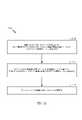
[0090]図6は、DL中心サブフレーム600の例示的なフォーマットを示す図である。DL中心サブフレーム600は制御部分602を含み得る。制御部分602は、DL中心サブフレーム600の初期部分または開始部分中に存在し得る。制御部分602は、DL中心サブフレーム600の様々な部分に対応する様々なスケジューリング情報および/または制御情報を含み得る。いくつかの構成では、制御部分602は、図6に示されているように、物理DL制御チャネル(PDCCH)であり得る。DL中心サブフレーム600は、DLデータ部分604をも含み得る。DLデータ部分604は、時々、DL中心サブフレーム600のペイロードと呼ばれることがある。DLデータ部分604は、スケジューリングエンティティ(たとえば、UEまたはBS)から従属エンティティ(たとえば、UE)にDLデータを通信するために利用される通信リソースを含み得る。いくつかの構成では、DLデータ部分604は、物理DL共有チャネル(PDSCH)であり得る。 [0090] FIG. 6 is a diagram illustrating an example format of a
[0091]DL中心サブフレーム600は、共通UL部分606をも含み得る。共通UL部分606は、ULバースト、共通ULバースト、および/または様々な他の好適な用語で呼ばれることがある。共通UL部分606は、DL中心サブフレーム600の様々な他の部分に対応するフィードバック情報を含み得る。たとえば、共通UL部分606は、制御部分602に対応するフィードバック情報を含み得る。フィードバック情報の非限定的な例は、ACK信号、NACK信号、HARQインジケータ、および/または様々な他の好適なタイプの情報を含み得る。共通UL部分606は、ランダムアクセスチャネル(RACH)プロシージャに関係する情報、スケジューリング要求(SR)、および様々な他の好適なタイプの情報など、追加または代替の情報を含み得る。図6に示されているように、DLデータ部分604の終端は、共通UL部分606の始端から時間的に分離され得る。この時間分離は、ギャップ、ガード期間、ガードインターバル、および/または様々な他の好適な用語で呼ばれることがある。この分離は、DL通信(たとえば、従属エンティティ(たとえば、UE)による受信動作)からUL通信(たとえば、従属エンティティ(たとえば、UE)による送信)への切替えのための時間を与える。当業者は、上記がDL中心サブフレームの一例にすぎず、同様の特徴を有する代替構造が、本明細書で説明される態様から必ずしも逸脱することなしに存在し得ることを理解されよう。 [0091] The
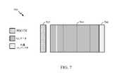
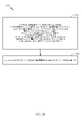
[0092]図7は、UL中心サブフレーム700の例示的なフォーマットを示す図である。UL中心サブフレーム700は制御部分702を含み得る。制御部分702は、UL中心サブフレーム700の初期部分または開始部分中に存在し得る。図7中の制御部分702は、図6を参照しながら上記で説明された制御部分602と同様であり得る。UL中心サブフレーム700はULデータ部分704をも含み得る。ULデータ部分704は、UL中心サブフレーム700のペイロードと呼ばれることがある。UL部分は、従属エンティティ(たとえば、UE)からスケジューリングエンティティ(たとえば、UEまたはBS)にULデータを通信するために利用される通信リソースを指し得る。いくつかの構成では、制御部分702はPDCCHであり得る。 [0092] FIG. 7 is a diagram illustrating an exemplary format of a
[0093]図7に示されているように、制御部分702の終端は、ULデータ部分704の始端から時間的に分離され得る。この時間分離は、ギャップ、ガード期間、ガードインターバル、および/または様々な他の好適な用語で呼ばれることがある。この分離は、DL通信(たとえば、スケジューリングエンティティによる受信動作)からUL通信(たとえば、スケジューリングエンティティによる送信)への切替えのための時間を与える。UL中心サブフレーム700は、共通UL部分706をも含み得る。図7中の共通UL部分706は、図6を参照しながら上記で説明された共通UL部分606と同様であり得る。共通UL部分706は、追加または代替の、チャネル品質インジケータ(CQI)に関係する情報、サウンディング基準信号(SRS)、および様々な他の好適なタイプの情報を含み得る。当業者は、上記がUL中心サブフレームの一例にすぎず、同様の特徴を有する代替構造が、本明細書で説明される態様から必ずしも逸脱することなしに存在し得ることを理解されよう。 [0093] As shown in FIG. 7, the end of the
[0094]一例では、フレームは、UL中心サブフレームとDL中心サブフレームとの両方を含み得る。この例では、フレーム中のDLサブフレームに対するUL中心サブフレームの比率は、送信されるULデータの量およびDLデータの量に基づいて動的に調整され得る。たとえば、より多くのULデータがある場合、DLサブフレームに対するUL中心サブフレームの比率は増加され得る。逆に、より多くのDLデータがある場合、DLサブフレームに対するUL中心サブフレームの比率は減少され得る。 [0094] In one example, a frame may include both a UL center subframe and a DL center subframe. In this example, the ratio of UL center subframes to DL subframes in a frame may be dynamically adjusted based on the amount of UL data and the amount of DL data to be transmitted. For example, if there is more UL data, the ratio of UL center subframes to DL subframes can be increased. Conversely, if there is more DL data, the ratio of UL central subframes to DL subframes can be reduced.
[0095]いくつかの状況では、2つまたはそれ以上の従属エンティティ(たとえば、UE)が、サイドリンク信号を使用して互いと通信し得る。そのようなサイドリンク通信の現実世界の適用例は、公共安全、近接サービス、UEネットワーク間中継、車両間(V2V)通信、あらゆるモノのインターネット(IoE)通信、IoT通信、ミッションクリティカルメッシュ、および/または様々な他の好適な適用例を含み得る。概して、サイドリンク信号は、スケジューリングエンティティ(たとえば、UEまたはBS)が、スケジューリングおよび/または制御目的のために利用され得るが、スケジューリングエンティティを通してその通信を中継することなしに、ある従属エンティティ(たとえば、UE1)から別の従属エンティティ(たとえば、UE2)に通信される信号を指し得る。いくつかの例では、サイドリンク信号は、(一般に、無認可スペクトルを使用するワイヤレスローカルエリアネットワークとは異なり)認可スペクトルを使用して通信され得る。 [0095] In some situations, two or more dependent entities (eg, UEs) may communicate with each other using sidelink signals. Real-world applications of such sidelink communications include public safety, proximity services, UE inter-network relay, vehicle-to-vehicle (V2V) communications, Internet of Things (IoE) communications, IoT communications, mission-critical meshes, and/or or various other suitable applications. In general, sidelink signals can be utilized by a scheduling entity (e.g., UE or BS) for scheduling and/or control purposes, but without relaying that communication through the scheduling entity. It may refer to a signal communicated from UE1) to another dependent entity (eg, UE2). In some examples, sidelink signals may be communicated using a licensed spectrum (unlike wireless local area networks, which typically use unlicensed spectrum).
[0096]UEは、リソースの専用セットを使用してパイロットを送信することに関連する構成(たとえば、無線リソース制御(RRC)専用状態など)、またはリソースの共通セットを使用してパイロットを送信することに関連する構成(たとえば、RRC共通状態など)を含む、様々な無線リソース構成において動作し得る。RRC専用状態において動作するとき、UEは、ネットワークにパイロット信号を送信するためのリソースの専用セットを選択し得る。RRC共通状態において動作するとき、UEは、ネットワークにパイロット信号を送信するためのリソースの共通セットを選択し得る。いずれの場合も、UEによって送信されたパイロット信号は、AN、またはDU、あるいはそれらの部分など、1つまたは複数のネットワークアクセスデバイスによって受信され得る。各受信ネットワークアクセスデバイスは、リソースの共通セット上で送信されたパイロット信号を受信および測定し、また、ネットワークアクセスデバイスが、それについて、UEのためのネットワークアクセスデバイスのモニタリングセットのメンバーであるUEに割り振られたリソースの専用セット上で送信されたパイロット信号を受信および測定するように構成され得る。受信ネットワークアクセスデバイスのうちの1つまたは複数、または(1つまたは複数の)受信ネットワークアクセスデバイスが、パイロット信号の測定値をそれに送信するCUは、UEのためのサービングセルを識別するために、またはUEのうちの1つまたは複数のためのサービングセルの変更を開始するために、測定値を使用し得る。
例示的な同期信号ブロック設計[0096] The UE may transmit pilot using a configuration (eg, Radio Resource Control (RRC) dedicated state, etc.) related to transmitting pilot using a dedicated set of resources, or a common set of resources. It may operate in various radio resource configurations, including configurations related to such (eg, RRC common state, etc.). When operating in RRC dedicated state, the UE may select a dedicated set of resources for transmitting pilot signals to the network. When operating in RRC common state, a UE may select a common set of resources for transmitting pilot signals to the network. In any case, the pilot signals transmitted by the UE may be received by one or more network access devices such as the AN, or DU, or parts thereof. Each receiving network access device receives and measures the pilot signals transmitted on the common set of resources, and the network access device for which the UE is a member of the network access device's monitoring set for the UE. It may be configured to receive and measure pilot signals transmitted on a dedicated set of allocated resources. one or more of the receiving network access devices, or the CU to which the receiving network access device(s) transmits measurements of the pilot signal, to identify the serving cell for the UE, or The measurements may be used to initiate serving cell changes for one or more of the UEs.
Exemplary sync block design
[0097]いくつかの態様では、セル同期プロシージャは、UE(たとえば、UE120)によるセル探索および同期を容易にするためにSSB中で信号のセットをブロードキャストする基地局(たとえば、BS110)を伴い得る。 [0097] In some aspects, a cell synchronization procedure may involve a base station (eg, BS 110) broadcasting a set of signals in SSB to facilitate cell search and synchronization by a UE (eg, UE 120). .
[0098]図8は、BS(たとえば、BS110)によってブロードキャストされるSSB800の構造の一例を示す。SSB800の構成は、図8に示されているように、PSS810と、SSS820と、PSS810とSSS820との間で多重化されたPBCH830とを含む。PBCH830は、復調基準信号(DMRS)信号などの基準信号を含み得る。したがって、BS110によって送信された各SSB800は、UE120が、PSS810に基づくシンボルタイミング、PSS810およびSSS820に基づくセル識別情報、ならびにPBCH830中で送られるマスタ情報ブロック(MIB)に基づく初期セルアクセスのために必要とされる他のパラメータなど、システムタイミング情報を決定するのを助け得る。 [0098] FIG. 8 shows an example structure of an
[0099]いくつかの実装形態では、図8に見られるように、PSS810およびSSS820は各々、時間領域中で1つのシンボルを占有し、PBCH830は、2つのシンボルを占有するが、2つの部分にスプリットされ、第1のハーフがPSS810とSSS820との間の1つのシンボル中にあり、第2のハーフがSSS820の後の第2のシンボル中にある。周波数領域では、PSS810およびSSS820は各々、127個のリソース要素またはサブキャリアを占有し得、PBCH830は288個のリソース要素を占有し得る。いくつかの実施形態では、リソース要素は、リソースブロックの1つサブキャリア中の1つシンボルを指す。たとえば、リソースブロックが12個のサブキャリアと7つのシンボルとを備えるとき、リソースブロックは、ノーマルサイクリックプレフィックスの場合は84個の(12個のサブキャリア*7つのシンボルの)リソース要素を備え得る(拡張CPの場合は72個)。SSB800の周波数ロケーションは、必ずしも周波数帯域の中心の6つのリソースブロック中にあるとは限らず、同期ラスタに応じて変動し得、チャネルラスタパラメータの関数であり得る。 [0099] In some implementations, as seen in FIG. 8,
[0100]基地局110は、UE120にシステムと同期するための機会を与えるためにSSB800を周期的に送信し得る。いくつかの態様では、基地局110は、たとえば、5msごとにPSSおよびSSSの1つのインスタンスのみを送信する代わりに、同期信号バースト(SSバースト)中でSSBの複数のインスタンスを送信し得る。SSバースト中で、複数のSSB送信が5msの時間ウィンドウ内で送られ得る。複数のSSB送信は、異なるロケーション中のUEに対するカバレージ拡張および/または指向性ビームを可能にし得る。たとえば、BSは、空間的に異なるロケーションを対象とする異なる送信ビームを使用してSSBを送信し得、それによって、それらの異なるロケーションの各々中のUEがSSBを受信することを可能にする。しかしながら、BS110は、特定の時間フレーム内で送信され得るSSBの数に関してあらかじめ定義されたルールによって限定され得る。その限定は、システムによって使用される特定のサブキャリア間隔とシステムが動作する周波数帯域とを含む、様々なファクタに基づき得る。 [0100]
[0101]図9に、様々なシステムパラメータに基づくSSB送信機会のパターンの例示的な構成900を示す。図9に示されているように、BS110のためのSSB送信機会の数と測定ウィンドウ(たとえば、5msのウィンドウ)内のSSB送信機会の対応するロケーションとは、BSによって採用されるサブキャリア間隔とBSが動作する周波数帯域とに依存し得る。UEは、周期的に構成された発見基準信号(DRS)測定タイミング構成(DMTC)期間ウィンドウに従ってセルDRSを測定し得る。 [0101] FIG. 9 shows an
[0102]DMTCは、サービングセルまたはネイバーセル、あるいは両方の測定のために構成され得る。さらに、DMTCは、様々な例では、周波数固有であり得るか、または複数の周波数に適用可能であり得る。各構成におけるスロットの長さは、その構成において使用されるサブキャリア間隔に応じて変動し得る。構成910では、120kHzのサブキャリア間隔が6GHz超周波数帯域(たとえば、60GHz周波数帯域)内で使用される。5msのウィンドウ内に、この構成910における基地局110は、L=64個のSSB(すなわち、スロットごとに2つのSSB)を送信することを可能にされ得、それらのSSBは、SSBのための割り振られたリソースの特定のパターンに従って送信されることを必要とされ得る。 [0102] The DMTC may be configured for serving cell or neighbor cell measurements, or both. Moreover, DMTC may be frequency-specific or applicable to multiple frequencies in various examples. The slot length in each configuration may vary depending on the subcarrier spacing used in that configuration. In
[0103]構成920では、240kHzのサブキャリア間隔が6GHz超(たとえば、60GHz)の周波数帯域内で使用され、SSB送信の最大数はL=64であり、それらのSSB送信は、SSBのための割り振られたリソースの特定のパターンに従って送信されることを必要とされ得る。64個のSSBは、SSバーストセットと呼ばれることがある。測定ウィンドウ内で可能にされるSSBのパターンおよび最大数は、他の構成では、使用されるサブキャリア間隔と、基地局110およびUE120が動作する周波数帯域とに応じて変動し得る。 [0103] In
[0104]図10に、周波数および時間リソース(たとえば、シンボル)に関するSSB送信機会の例示的な構成1000を示す。簡単のために、図10に、3つのSSB送信機会を示すが、SSバーストセット内のSSB送信機会の数は、6GHzの周波数帯域を超えた動作の場合はSSバーストセット中でL=64個のSSブロックになるなど、より多くなり得る(3GHzを下回るキャリア周波数の場合、Lは4になり得、3GHzと6GHzとの間のキャリア周波数の場合、Lは8になり得る)。場合によっては、SSB送信のために割り振られた測定ウィンドウ内にあらかじめ定義されたロケーションがあり得る。たとえば、SSB送信機会1010、1020、および1030に対応するリソースが、SSBを送信することに割り振られ得、基地局は、SSB送信機会1010、1020、または1030のすべて、以外、または任意の組合せで送信することを選定し得る。 [0104] FIG. 10 shows an
[0105]基地局110は、SSB送信機会1020中で送信することを控えながらSSB送信機会1010および1030中でSSBを送信することを選定し得る。このシナリオでは、基地局110は、「論理的に連続しない」方式でSSB送信機会1010および1030中でSSBを送信し、すなわち、基地局110がSSBを送信しないSSB送信機会(1010と1030と)の間に(たとえば、SSB送信機会1020に対応する)介在するSSB送信機会があり得る。代替的に、基地局110は、代わりに、SSB送信機会1010および1020中でSSBを送信し得、その場合、送信されるSSBは論理的に連続すると見なされる。
[0106]上記で説明したように、セルへの最初のアクセスの場合、UEは、システム情報を取得し得る。システム情報は、場合によっては、最小システム情報(MSI)ならびに他のシステム情報(OSI)を含み得る。MSIを使用して、UEは、セルとともにランダムアクセスチャネル(RACH)プロシージャを実行することが可能である。場合によっては、MSIは、(LTEにおけるマスタ情報ブロック(MIB)と同様の)PBCHによって搬送される情報ならびに残存最小システム情報(RMSI)を含む。(MIBと同様の)PBCHによって搬送される情報は、セル(BS)から他の情報を取得するためにUEによって使用される情報である。RMSIは、セル(BS)へのUEのアクセスに関係する情報ならびにセル中のすべてのUEのための共通の無線リソース構成を含む。RMSIは、システム情報ブロック1(SIB1)と互換的に呼ばれることがあり、RMSI CORESETは、タイプ0物理ダウンリンク制御チャネル(PDCCH)共通探索空間CORESET(すなわち、タイプ0物理ダウンリンク制御チャネル(PDCCH)共通探索空間のためのCORESET構成)と互換的に呼ばれることがあり、OSI CORESETは、タイプ0a物理ダウンリンク制御チャネル(PDCCH)共通探索空間CORESETと互換的に呼ばれることがある。RMSIは、上記で説明されたように、物理ダウンリンク共有チャネル(PDSCH)によって搬送される。UEは、PDCCH中で送られた情報に基づいてPDSCHのリソースを使用して通信するようにスケジュールされる。PDSCHはまた、OSIを搬送し得る。 [0106] As explained above, for the first access to a cell, the UE may obtain system information. System information may optionally include minimum system information (MSI) as well as other system information (OSI). Using MSI, a UE can perform random access channel (RACH) procedures with a cell. In some cases, the MSI includes information carried by the PBCH (similar to the Master Information Block (MIB) in LTE) as well as the Minimum Remaining System Information (RMSI). The information carried by the PBCH (similar to the MIB) is the information used by the UE to obtain other information from the cell (BS). The RMSI contains information related to UE access to a cell (BS) as well as a common radio resource configuration for all UEs in the cell. RMSI is sometimes referred to interchangeably as System Information Block 1 (SIB1), and RMSI CORESET is the
[0107]RMSIをスケジュールするPDCCHリソースは、SSBに関連するRMSI PDCCHモニタリングウィンドウ内の制御リソースセット(CORESET)中でBSによって送信され得る。言い換えれば、PDCCHは、CORESETにマッピングされる。RMSI PDCCHモニタリングウィンドウは、オフセットと、持続時間(たとえば、長さ)と、周期とを有する。 [0107] The PDCCH resources that schedule the RMSI may be transmitted by the BS in the control resource set (CORESET) within the RMSI PDCCH monitoring window associated with the SSB. In other words, PDCCH is mapped to CORESET. The RMSI PDCCH monitoring window has an offset, a duration (eg, length), and a period.
[0108]CORESETは、周波数領域および時間領域に関して定義され得る。周波数領域では、CORESETは、CORESET帯域幅と呼ばれることがあるリソースブロック(PRB)の数(たとえば、24個のPRB、48個のPRB)によって定義される(たとえば、6つのPRBの倍数)。場合によっては、PRBは、連続していることも連続していないこともある。時間領域中で、CORESETは、OFDMシンボルの数によって定義される。シンボルは、時間リソースを指す。たとえば、タイムスロット中のダウンリンク制御領域は、最高3つのOFDMシンボルを有し得る。いくつかの実施形態では、CORESETは、1つのシンボルのCORESET、2つのシンボルのCORESET、または3つのシンボルCORESETであり得る。 [0108] CORESET may be defined in terms of the frequency domain and the time domain. In the frequency domain, a CORESET is defined by the number of resource blocks (PRBs) (eg, 24 PRBs, 48 PRBs), sometimes referred to as the CORESET bandwidth (eg, multiples of 6 PRBs). In some cases, PRBs may or may not be contiguous. In the time domain, CORESET is defined by the number of OFDM symbols. Symbols refer to time resources. For example, the downlink control region in a timeslot may have up to 3 OFDM symbols. In some embodiments, the CORESET may be a 1-symbol CORESET, a 2-symbol CORESET, or a 3-symbol CORESET.
[0109]場合によっては、RMSI CORESETは、RMSIを搬送するPDSCHをスケジュールするためのPDCCHリソースがマッピングされるCORESETである。場合によっては、RMSI CORESET構成は、SSBによって搬送されるPBCH中でシグナリングされ得る。RMSI CORESET構成は、RMSI CORESET帯域幅(BW)(たとえば、RMSI CORESET中のRMSI CORESET PRBの数は、RMSI CORESET帯域幅(BW)と呼ばれることがある)と、RMSI周波数オフセット値と、OFDMシンボルとに関係する情報を含み得る。場合によっては、OSI CORESETは、OSIを搬送するPDSCHをスケジュールするためのPDCCHリソースがマッピングされるCORESETである。 [0109] In some cases, the RMSI CORESET is the CORESET to which the PDCCH resources for scheduling the PDSCH carrying the RMSI are mapped. In some cases, the RMSI CORESET configuration may be signaled in the PBCH carried by the SSB. The RMSI CORESET configuration consists of an RMSI CORESET bandwidth (BW) (e.g., the number of RMSI CORESET PRBs in the RMSI CORESET is sometimes referred to as the RMSI CORESET bandwidth (BW)), an RMSI frequency offset value, an OFDM symbol, and may include information related to In some cases, the OSI CORESET is a CORESET to which PDCCH resources for scheduling PDSCH carrying OSI are mapped.
[0110]本明細書で説明するいくつかの実施形態は、UEなどのワイヤレス通信デバイスが、周波数および時間領域中でのRMSI CORESETとOSI CORESETとのロケーションを決定することを可能にすることを対象とする。RMSI CORESETを受信することによって、UEは、どのUEがRMSIを搬送するPDSCHを受信し、復号することが可能であるのかに基づいてRMSI(タイプ0 PDCCH共通探索空間)CORESET中でPDCCH(タイプ0 PDCCH)を受信することが可能になる。また、UEは、周波数および時間領域中でのRMSI CORESETのロケーションに基づいて周波数および時間領域中でのOSI CORESETのロケーションを決定し得る。 [0110] Some embodiments described herein are directed to enabling a wireless communication device, such as a UE, to determine the location of the RMSI and OSI coresets in the frequency and time domains. and By receiving the RMSI CORESET, the UE can determine the PDCCH (
[0111]本明細書では、周波数領域と時間領域との中でのRMSI CORESETのロケーションが、それぞれ、RMSI CORESETの周波数ロケーションおよび時間ロケーションと互換的に呼ばれることがあることに注意されたい。また、本明細書では、周波数領域と時間領域との中でのOSI CORESETのロケーションが、それぞれ、OSI CORESETの周波数ロケーションおよび時間ロケーションと互換的に呼ばれることがあることに注意されたい。
例示的なRMSIオフセット設計[0111] Note that the location of the RMSI CORESET in the frequency domain and the time domain may be referred to herein interchangeably as the frequency location and time location of the RMSI CORESET, respectively. Also note that herein the location of an OSI CORESET in the frequency domain and time domain may be referred to interchangeably as the OSI CORESET's frequency location and time location, respectively.
Exemplary RMSI Offset Design
[0112]いくつかの実施形態では、周波数および時間領域中でのRMSI CORESETのロケーションを決定することは、周波数および時間領域中でのSSB送信のロケーションに基づき得る。 [0112] In some embodiments, determining the location of the RMSI CORESET in the frequency and time domain may be based on the location of the SSB transmission in the frequency and time domain.
[0113]図11は、ワイヤレス通信のための例示的な動作1100を示す流れ図である。動作1100は、周波数領域中でのRMSI CORESETのロケーションを決定するために、たとえば、UE(たとえば、UE120)によって実行され得る。動作1100は、1102において、同期信号ブロック(SSB)によって搬送される物理ブロードキャストチャネル(PBCH)中でタイプ0物理ダウンリンク制御チャネル(PDCCH)共通探索空間制御リソースセット(CORESET)構成と物理リソースブロック(PRB)グリッドオフセットとを受信すること、タイプ0 PDCCH共通探索空間CORESET構成が、SSBのPRBの周波数ロケーションに対するタイプ0 PDCCH共通探索空間CORESETリソースブロック(PRB)の周波数ロケーションに関係する1つまたは複数のオフセットに対応する1つまたは複数のオフセット値を示すインジケーションを備える、を行うことによって開始する。1104において、動作1100は、PRBグリッドオフセットを適用することによってタイプ0 PDCCH共通探索空間CORESETのPRBグリッドとSSBのPRBグリッドをアラインすることによって続く。1106において、動作1100は、UEによって記憶されたマッピングを使用して1つまたは複数のオフセット値にインジケーションをマッピングすることによって続く。1108において、動作1100は、1つまたは複数のオフセット値とSSB PRBの周波数ロケーションとに基づいてタイプ0 PDCCH共通探索空間CORESET PRBの周波数ロケーションを決定することによって続く。1110において、動作1100は、タイプ0 PDCCH共通探索空間CORESET中でタイプ0 PDCCHを受信することによって続く。 [0113] FIG. 11 is a flow diagram illustrating
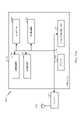
[0114]図11Aに、図11に示される動作のうちの1つまたは複数など、本明細書で開示される技法のための動作を実行するように構成された(たとえば、ミーンズプラスファンクション構成要素に対応する)様々な構成要素を含み得るワイヤレス通信デバイス1100Aを示す。通信デバイス1100Aは、トランシーバ1112に結合された処理システム1114を含む。トランシーバ1112は、アンテナ1113を介して通信デバイス1100Aのための信号を送信および受信するように構成される。処理システム1114は、処理信号などの通信デバイス1100Aのための処理機能を実行するように構成され得る。 [0114] FIG. 11A illustrates a means-plus-function component configured to perform operations for the techniques disclosed herein, such as one or more of the operations shown in FIG. ) shows a
[0115]処理システム1114は、バス1121を介してコンピュータ可読媒体/メモリ1111に結合されたプロセッサ1109を含む。いくつかの態様では、コンピュータ可読媒体/メモリ1111は、プロセッサ1109によって実行されたとき、プロセッサ1109に、図11に示す動作のうちの1つもしくは複数または本明細書で説明される様々な技法を実行するための他の動作を実行させる命令を記憶するように構成される。 [0115]
[0116]いくつかの態様では、処理システム1114は、図11中の1102に示す動作のうちの1つまたは複数を実行するための受信構成要素1120をさらに含む。さらに、処理システム1114は、図11中の1104に示す動作のうちの1つまたは複数を実行するためのアライン構成要素1122を含む。さらに、処理システム1114は、図11中の1106に示す動作のうちの1つまたは複数を実行するためのマッピング構成要素1124を含む。また、処理システム1114は、図11中の1108に示す動作のうちの1つまたは複数を実行するための決定構成要素1126を含む。さらに、処理システム1114は、図11中の1110に示す動作のうちの1つまたは複数を実行するための受信構成要素1128を含む。 [0116] In some aspects, the
[0117]受信構成要素1120、アライン構成要素1122、マッピング構成要素1124、決定構成要素1126、および受信構成要素1128は、バス1121を介してプロセッサ1109に結合され得る。いくつかの態様では、受信構成要素1120、アライン構成要素1122、マッピング構成要素1124、決定構成要素1126、および受信構成要素1128は、ハードウェア回路であり得る。いくつかの態様では、受信構成要素1120、アライン構成要素1122、マッピング構成要素1124、決定構成要素1126、および受信構成要素1128は、プロセッサ1109上で実行され、動作するソフトウェア構成要素であり得る。 [0117]
[0118]周波数領域中でのRMSI CORESETのロケーションを決定することに関して、上記で説明したように、UEは、PBCH中でPRBグリッドオフセットおよびRMSI CORESET構成を受信し得、これは、上記で説明したように、1つまたは複数のRMSI周波数オフセット値のインジケーションを含む。UEは、最初に、PRBグリッドオフセットを適用することによってRMSI CORESETのPRBグリッドとSSBのPRBグリッドをアラインし得る。SSBのPRBグリッドは、周波数帯域幅全体に対応するより大きい周波数リソースグリッド上の、SSBを送信するために割り振られたPRBのセットを指す。同様に、RMSI CORESETのPRBグリッドは、周波数帯域幅全体に対応するより大きい周波数リソースグリッド上の、RMSI CORESETを送信するために割り振られたPRBのセットを指す。UEは、次いで、SSB周波数ロケーションに関するRMSI CORESET周波数ロケーションのインジケーションを与えるRMSI CORESET帯域幅ならびに周波数オフセット値を決定するためにインジケーションを使用し得る。 [0118] As explained above with respect to determining the location of the RMSI CORESET in the frequency domain, the UE may receive the PRB grid offset and the RMSI CORESET configuration in the PBCH, which is the As such, it contains an indication of one or more RMSI frequency offset values. The UE may first align the PRB grid of the RMSI CORESET and the PRB grid of the SSB by applying the PRB grid offset. A PRB grid for SSB refers to a set of PRBs allocated for transmitting SSB on a larger frequency resource grid corresponding to the entire frequency bandwidth. Similarly, the PRB grid of the RMSI CORESET refers to the set of PRBs allocated to transmit the RMSI CORESET on a larger frequency resource grid corresponding to the entire frequency bandwidth. The UE may then use the indication to determine the RMSI CORESET bandwidth as well as the frequency offset value giving the indication of the RMSI CORESET frequency location for the SSB frequency location.
[0119]たとえば、いくつかの実施形態では、RMSI CORESETは、SSBと時分割多重化(TDM)され得る。いくつかの実施形態では、(PBCH中でシグナリングされるPRBグリッドオフセットを使用してRMSI CORESET PRBグリッドと物理リソースブロック(PRB)グリッドをアラインした後の)RMSI CORESETとSSBとの間の周波数オフセットは、SSBの最低の(すなわち、最小の)PRB(すなわち、PRB0)からRMSI CORESETの最低の(すなわち、最小の)PRB(すなわち、PRB0)までの周波数差であり得る。一例として、SSBのPRBグリッドとRMSI CORESETのPRBグリッドとがアラインしされるとき、ゼロのオフセット値は、SSBの最低の(すなわち、最小の)PRBとRMSI CORESETの最低の(すなわち、最小の)PRBとが同じインデックス番号または周波数を有することを示し得る。 [0119] For example, in some embodiments, the RMSI CORESET may be time division multiplexed (TDM) with SSB. In some embodiments, the frequency offset between the RMSI CORESET and the SSB (after aligning the RMSI CORESET PRB grid with the physical resource block (PRB) grid using the PRB grid offset signaled in the PBCH) is , the frequency difference from the lowest (ie, smallest) PRB of the SSB (ie, PRB0) to the lowest (ie, smallest) PRB of the RMSI CORESET (ie, PRB0). As an example, when the PRB grid of SSB and the PRB grid of the RMSI CORESET are aligned, the zero offset value is the lowest (i.e., smallest) PRB of SSB and the lowest (i.e., smallest) PRB of RMSI CORESET. PRBs have the same index number or frequency.
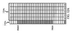
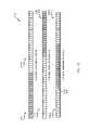
[0120]図12A~図12Cの各々に、いくつかの連続するSSB PRBといくつかの連続するRMSI CORESET PRBとをそれぞれ含むPRBグリッドを示す。図12A~図12Cの各々に示されるように、SSB PRBとRMSI CORESET PRBとは、それらが最大数の重複するPRBを有するように選択される。たとえば、各PRBグリッド中の第1の列(列1202a、1202b、および1202c)に、(たとえば、影付きとして示される)SSB PRBを含む(行として示される)PRBを示す。各PRBグリッド中の残りの列(列1204a、1204b、および1204c)の各々に、(たとえば、影付きとして示される)RMSI CORESET PRBを含むPRBを示す。第1の列(たとえば、1202a、1202bまたは1202c)から右に向かう列は、(RBに対応しないが、PRBグリッドのためのラベルであるグリッドの最後の行に示すように)0、1、...nまで順序付けされており、これは、RMSI CORESET PRBを決定するために使用されるオフセットに対応する。異なる列は、異なる時間における送信を暗示することを意図していない。図示のように、可能なオフセットの数は、RMSI CORESET PRBがSSB PRBと完全に重複するあらゆるオフセット値である。 [0120] Each of Figures 12A-12C shows a PRB grid that includes several consecutive SSB PRBs and several consecutive RMSI CORESET PRBs, respectively. As shown in each of FIGS. 12A-12C, the SSB PRBs and RMSI CORESET PRBs are selected such that they have the maximum number of overlapping PRBs. For example, the first column (
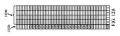
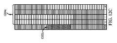
[0121]たとえば、図12Aでは、20個のSSB PRBと24個のRMSI CORESET PRBとがある。SSB PRBとRMSI CORESET PRBとの間でPRBが重複する数を最大化するために、24個のRMSI CORESET PRBが選択され、各々があるオフセットに対応する5つの異なるシナリオのうちの1つ中で送信され得る。第1のシナリオでは、SSBの開始PRB(PRB0)は、RMSI CORESETの開始PRBと同じである。そのような例では、SSB PRBに関するRMSI CORESETの周波数オフセットは0(ゼロ)である。第2のシナリオでは、RMSI CORESET周波数は、SSBの開始PRB(PRB0)を下回るPRBとして開始する。そのような例では、SSB PRBに関するRMSI CORESETの周波数オフセットは1である。図12Aに示すように、RMSI CORESET送信のために使用されるサブキャリア間隔は、SSB送信のために使用されるサブキャリア間隔と同じである。しかしながら、図12Bおよび図12Cでは、RMSI CORESET送信のために使用されるサブキャリア間隔(SCS)は、SSB送信のために使用されるサブキャリア間隔と異なる。たとえば、図12Bでは、RMSI SCSは、SSB SCSの1/2である。図12Cでは、RMSI SCSは、SSB SCSのそれの2倍である。したがって、図12Bでは、RMSI CORESETの各連続は、周波数でSSBのSCSの1/2のRMSI CORESETのシフトである。さらに、図12Cでは、RMSI CORESETの各連続は、周波数でSSBのSCSの2倍のRMSI CORESETのシフトである。本明細書における実施形態では、RMSI(すなわち、タイプ0 PDCCH共通探索空間)CORESETのサブキャリア間隔は、PDCCH(たとえば、タイプ0 PDCCH)のサブキャリア間隔によって定義されることに留意されたい。言い換えれば、タイプ0 PDCCH共通探索空間CORESETのサブキャリア間隔は、タイプ0 PDCCHのサブキャリア間隔と同じであり得る。 [0121] For example, in FIG. 12A, there are 20 SSB PRBs and 24 RMSI CORESET PRBs. In order to maximize the number of PRB overlaps between the SSB PRBs and the RMSI CORESET PRBs, 24 RMSI CORESET PRBs were selected in one of five different scenarios, each corresponding to an offset. can be sent. In the first scenario, the SSB starting PRB (PRB0) is the same as the RMSI CORESET starting PRB. In such an example, the RMSI CORESET frequency offset for the SSB PRB is 0 (zero). In the second scenario, the RMSI CORESET frequency starts as a PRB below the SSB starting PRB (PRB0). In such an example, the frequency offset of the RMSI CORESET for the SSB PRB is one. As shown in FIG. 12A, the subcarrier spacing used for RMSI CORESET transmission is the same as the subcarrier spacing used for SSB transmission. However, in Figures 12B and 12C, the subcarrier spacing (SCS) used for RMSI CORESET transmissions is different than the subcarrier spacing used for SSB transmissions. For example, in FIG. 12B, the RMSI SCS is half the SSB SCS. In FIG. 12C, the RMSI SCS is twice that of the SSB SCS. Thus, in FIG. 12B, each succession of RMSI CORESET is a shift of RMSI CORESET of 1/2 SCS of SSB in frequency. Further, in FIG. 12C, each successive RMSI CORESET is a shift of the RMSI CORESET of twice the SCS of SSB in frequency. Note that in the embodiments herein, the RMSI (ie,
[0122]いくつかの実施形態では、周波数オフセットは、RMSI CORESETサブキャリア間隔(SCS)に関してPRBの整数倍のステップである。言い換えれば、周波数オフセットのオフセット値は、オフセットステップの倍数単位であり、RMSI CORESETの少なくともオフセットステップサイズおよびサブキャリア間隔(SCS)に基づく。いくつかの実施形態では、周波数オフセットのオフセット値はまた、RMSI CORESET帯域幅に依存する。いくつかの実施形態では、オフセットステップサイズは、RMSI CORESET帯域幅またはSSB SCSまたはRMSI SCSまたはそれらの任意の組合せに依存する。オフセットステップサイズは、1つのPRB以上(たとえば、2つのPRB、6つのPRB、8つのPRBなど)であり得る。 [0122] In some embodiments, the frequency offset is in steps of an integer multiple of PRBs with respect to the RMSI CORESET subcarrier spacing (SCS). In other words, the offset value of the frequency offset is in multiples of offset steps and is based on at least the offset step size and subcarrier spacing (SCS) of the RMSI CORESET. In some embodiments, the offset value of the frequency offset also depends on the RMSI CORESET bandwidth. In some embodiments, the offset step size depends on the RMSI CORESET bandwidth or SSB SCS or RMSI SCS or any combination thereof. The offset step size may be 1 PRB or greater (eg, 2 PRBs, 6 PRBs, 8 PRBs, etc.).
[0123]RMSI CORESETを受信しているUE(たとえば、120)がRMSI CORESET周波数リソースのロケーションを決定することが可能であるために、いくつかの実施形態では、BS(たとえば、110)は、UEにRMSI CORESET PRBとSSB PRBとの間のオフセットに対応するオフセット値のインジケーションを送信し得る。このインジケーションは、SSBによって搬送されるPBCH中でRMSI CORESET構成によって搬送され得る。そのような実施形態では、RMSI CORESET SCSを知ると、UEは、次いで、あるRMSI CORESET BWおよびオフセット値にインジケーション中に含まれている情報をマッピングするために(たとえば、ハッシュ関数、ハッシュマップまたは任意の他のタイプのマッピングなどの)マッピングを使用し得る。次に、UEは、(UEに知られている)SSBのPRBのロケーションを使用し、RMSI CORESET PRBのロケーションを決定するために受信されたオフセット値を適用し得る。 [0123] To enable a UE (eg, 120) receiving an RMSI CORESET to determine the location of RMSI CORESET frequency resources, in some embodiments the BS (eg, 110) may send an indication of an offset value corresponding to the offset between the RMSI CORESET PRB and the SSB PRB to . This indication may be carried by the RMSI CORESET structure in the PBCH carried by the SSB. In such embodiments, upon knowing the RMSI CORESET SCS, the UE may then map the information contained in the indication to some RMSI CORESET BW and offset value (e.g., a hash function, hash map or (such as any other type of mapping) may be used. The UE may then use the location of the SSB PRB (known to the UE) and apply the received offset value to determine the location of the RMSI CORESET PRB.
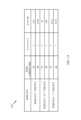
[0124]しかしながら、説明されたように、RMSI SCSに応じてRMSI CORESETには多数の可能な周波数オフセット値があり得る。図13に、BSが(RSMI CORE SET SCSおよびRMSI CORESET BWに応じて)様々なシナリオにおけるインジケーション中でUEに示し得る可能ないくつかの周波数オフセット値を示す例示的な表1300を示す。図示のように、RMSI CORESET SCSに応じて、BSがUEに示すために多数の可能な周波数オフセット値があり得る。たとえば、RMSI CORESET BWが24であり、SSB BWが20であり、RMSI CORESET SCS=SSB SCSである場合、RMSI CORESETのために5つの可能なオフセット値がある。さらに、RMSI CORESET BWが48であり、SSB BWが20であり、RMSI CORESET SCS=SSB SCSである場合、RMSI CORESETのために29個の可能なオフセット値がある。そのような場合、RMSI CORESET PRBのロケーションを決定するためにUEによって使用されるマッピングが表1300に示すオフセット値に基づく場合、BSは、相応して、オフセット値およびRMSI CORESET BWを示すインジケーションをUEに送信するために多数のビット(たとえば、5+29=RMSI CORESET SCSのための34個の可能な組合せ=SSB SCSを表す6ビット)を使用する必要があり得る。しかしながら、インジケーション中で多数のビットを送信することは準最適であり得る。さらに、いくつかの組合せについて、いくつかの周波数オフセットが、構成シグナリングオーバーヘッドをさらに低減するために構成から除外される可能性がある。 [0124] However, as explained, there can be many possible frequency offset values for the RMSI CORESET depending on the RMSI SCS. FIG. 13 shows an exemplary table 1300 showing some possible frequency offset values that the BS may indicate to the UE in indications in various scenarios (depending on the RSMI CORE SET SCS and RMSI CORE SET BW). As shown, there can be many possible frequency offset values for the BS to indicate to the UE, depending on the RMSI CORESET SCS. For example, if the RMSI CORESET BW is 24, the SSB BW is 20, and RMSI CORESET SCS=SSB SCS, then there are 5 possible offset values for the RMSI CORESET. Further, if the RMSI CORESET BW is 48, the SSB BW is 20, and RMSI CORESET SCS=SSB SCS, then there are 29 possible offset values for the RMSI CORESET. In such a case, if the mapping used by the UE to determine the location of the RMSI CORESET PRB is based on the offset values shown in table 1300, the BS will correspondingly display an indication of the offset value and the RMSI CORESET BW. It may be necessary to use a large number of bits (eg, 5+29 = 34 possible combinations for the RMSI CORESET SCS = 6 bits representing the SSB SCS) to transmit to the UE. However, sending a large number of bits in an indication may be sub-optimal. Additionally, for some combinations, some frequency offsets may be left out of the configuration to further reduce configuration signaling overhead.
[0125]したがって、いくつかの実施形態では、UEは、BSがより効率的でより少ないリソース消費の方式でUEにインジケーションを送信することを可能にするマッピングで構成され得る。より詳細には、マッピングにより、インジケーション中でオフセット値を示すためにより少ない数のビットがUEに送られることが可能になる。 [0125] Thus, in some embodiments, a UE may be configured with a mapping that allows the BS to send indications to the UE in a more efficient and less resource consuming manner. More specifically, the mapping allows fewer bits to be sent to the UE to indicate the offset value in the indication.
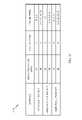
[0126]図14に、BSが(RSMI CORESET SCSおよびRMSI CORESET BWに応じて)様々なシナリオにおけるインジケーション中でUEに示し得るより少ない可能ないくつかの周波数オフセット値を示す例示的な表1400を示す。したがって、表1400に示す構成およびオフセット値に基づくマッピングにより、より少ない数のビットがUEへのインジケーション中にBSによって送信されることが可能になる。 [0126] FIG. 14 shows an exemplary table 1400 showing some possible less frequency offset values that the BS may indicate to the UE during indications in various scenarios (depending on the RSMI CORESET SCS and RMSI CORESET BW). indicates Therefore, mapping based on the configuration and offset values shown in table 1400 allows a smaller number of bits to be sent by the BS during indication to the UE.
[0127]図示のように、表は、RMSI CORESETのSCSとSSBのSCSとに応じて異なるRMSI周波数オフセット値を与える。しかしながら、図13の表1300と比較して、表1400のオフセットステップは、表1300のオフセットステップよりも大きい。たとえば、RMSI SCS=SSB SCSであり、RMSI CORESET帯域幅が24個のPRBである場合、図12Aに示すように、オフセットステップは2として構成され得る。したがって、オフセット値は、表1300に示すような0、1、2、3、および4ではなくPRB中に0、2、および4(3つのみのオフセット値)であり得る。別の例では、RMSI SCS=SSB SCSであり、RMSI CORESET帯域幅が48である場合、図示のように、オフセットステップは6になり得る。したがって、オフセット値は、表1300に示すような0~28(29個のオフセット値)ではなく0、6、12、18、24(5つのみのオフセット値)であり得る。したがって、上記で説明したように、表1400に示す構成およびオフセット値に基づくマッピングでUEとBSとを構成することにより、UEがオフセット値を決定することを依然として可能にしながら、(RMSI CORESET構成によって搬送されるインジケーション中での)UEへのより少数のビットの送信が可能になる。たとえば、RMSI CORESET PRBのロケーションを決定するためにUEによって使用されるマッピングが表1400に示されたオフセット値に基づく場合、BSは、相応して、オフセット値およびRMSI CORESET BWを示すインジケーションをUEに送信するためにより少数のビット(たとえば、3+5=RMSI CORESET SCSのための8個の可能な組合せ=SSB SCSを表す3ビット)を使用する必要があり得る。これらのより少数のビットは、RMSI CORESET BWとRMSI CORESETのためのオフセット値とを示すためにRMSI CORESET構成中に含まれるものであり得る。説明したように、UEは、RMSI CORESET BWおよびオフセット値にRMSI CORESET構成中で受信されたビットをマッピングする表、ハッシュ関数などを含み得る。特に、RMSI CORESET構成中で受信されたビットはオフセット値に直接対応しないことがあり、ビット値が、直接的にオフセット値でないことを意味する。 [0127] As shown, the table provides different RMSI frequency offset values depending on the SCS of the RMSI CORESET and the SCS of the SSB. However, compared to table 1300 of FIG. 13, the offset steps of table 1400 are larger than the offset steps of table 1300 . For example, if RMSI SCS=SSB SCS and the RMSI CORESET bandwidth is 24 PRBs, the offset step may be configured as 2, as shown in FIG. 12A. Therefore, the offset values can be 0, 2, and 4 (only three offset values) in the PRB instead of 0, 1, 2, 3, and 4 as shown in table 1300 . In another example, if RMSI SCS=SSB SCS and the RMSI CORESET bandwidth is 48, then the offset step can be 6, as shown. Therefore, the offset values can be 0, 6, 12, 18, 24 (only 5 offset values) instead of 0-28 (29 offset values) as shown in table 1300 . Thus, as explained above, configuring the UE and BS with a mapping based on the configuration and offset values shown in table 1400 while still allowing the UE to determine the offset value (by the RMSI CORESET configuration It allows transmission of fewer bits to the UE (in the indication that is carried). For example, if the mapping used by the UE to determine the location of the RMSI CORESET PRB is based on the offset values shown in table 1400, the BS will correspondingly display an indication indicating the offset value and the RMSI CORESET BW to the UE. (eg, 3+5=8 possible combinations for RMSI CORESET SCS=3 bits representing SSB SCS) to transmit to. These fewer bits may be included in the RMSI CORESET configuration to indicate the RMSI CORESET BW and the offset value for the RMSI CORESET. As described, the UE may include tables, hash functions, etc. that map the bits received in the RMSI CORESET configuration to the RMSI CORESET BW and offset values. In particular, the bits received in the RMSI CORESET structure may not directly correspond to offset values, meaning that the bit values are not directly offset values.
[0128]いくつかの実施形態では、RMSI CORESETおよびSSBがTDMされるのではなく、RMSI CORESETとSSBとが周波数分割多重化(FDM)され得る。図15に、RMSI CORESETがSSBとどのようにFDMされ得るのかの3つの例を示す。行の各列は、周波数ロケーション(たとえば、PRB)を表す。RMSI CORESETがSSBとFDMされ得る異なる方法の一例を示す3つの行の各々は、UEによって同時に受信される周波数リソース(そのうちのいくつかは、RMSI CORESETのために使用され、そのうちのいくつかはSSBのためにユーザ)を表す。図示のように、RMSI CORESETは、SSBの上部の周波数、下部の周波数、または両側(上部と下部との周波数)中でFDMされ得る。たとえば、RMSI CORESET1504aは、例(a)ではSSBの上側1502aでFMDされる。例(b)では、RMSI CORESET1504bは、SSBの下側1502bでFDMされる。例(c)では、RMSI CORESET1504cは、SSBの両側1502cでFDMされる。 [0128] In some embodiments, rather than TDM the RMSI CORESET and SSB, the RMSI CORESET and SSB may be frequency division multiplexed (FDM). FIG. 15 shows three examples of how the RMSI CORESET can be FDMed with SSB. Each column of a row represents a frequency location (eg, PRB). Each of the three rows showing an example of different ways in which the RMSI CORESET can be FDMed with SSB represents frequency resources (some of which are used for RMSI CORESET, some of which are used for SSB) simultaneously received by the UE. user). As shown, the RMSI CORESET can be FDMed in the top frequency, bottom frequency, or both sides (top and bottom frequencies) of the SSB. For example, the
[0129]RMSI CORESETがSSBとFDMされるとき、RMSI CORESET構成は、RMSI CORESET PRBとSSB PRBとの間のオフセットに対応するオフセット値を示すインジケーションを含み得る。このインジケーションは、PBCH中でRMSI CORESET構成によって搬送した。そのような実施形態では、RMSI CORESET SCSを知ると、UEは、次いで、あるRMSI CORESET BWおよびオフセット値にインジケーション中に含まれている情報をマッピングするために(たとえば、ハッシュ関数、ハッシュマップまたは任意の他のタイプのマッピングなどの)マッピングを使用し得る。次に、UEは、(UEに知られている)SSBのPRBリソースのロケーションを使用し、RMSI CORESET PRBのロケーションを決定するために受信されたオフセット値を適用し得る。いくつかの実施形態では、マッピングは、表1600に示す例示的な構成およびオフセット値に基づき得る。 [0129] When the RMSI CORESET is FDMed with SSB, the RMSI CORESET configuration may include an indication of an offset value corresponding to the offset between the RMSI CORESET PRB and the SSB PRB. This indication was carried by the RMSI CORESET structure in the PBCH. In such embodiments, upon knowing the RMSI CORESET SCS, the UE may then map the information contained in the indication to some RMSI CORESET BW and offset value (e.g., a hash function, hash map or (such as any other type of mapping) may be used. The UE may then use the location of the PRB resource for the SSB (known to the UE) and apply the received offset value to determine the location of the RMSI CORESET PRB. In some embodiments, the mapping may be based on the exemplary configuration and offset values shown in table 1600.
[0130]図16に、RMSI SCSとSSB SCSとが同じであるのか異なるのかに応じた異なるオフセット値を示す例示的な表1600を示す。たとえば、RMSI SCS=SSB SCSであり、RMSI CORESET帯域幅が24である場合、オフセット値は、-(20+G)、{6,12,18,24}+G0であり得る。そのようなオフセット値は、SSBが周波数-20PRBとして開始し、その後ガード期間(G)が続き、その後、たとえば、6つのPRB(PDCCHのための制御チャネル要素(CCE)が6つのPRBである)の単位でRMSI CORESETの24個のPRBが続くことを示し得る。TDMの例と同様に、FDMの例では、表1600は、特定のRMSI SCSおよびRMSI CORESET BWごとに物理的に可能であるよりも少数のオフセット値を含む。したがって、RMSI CORESET BWおよびオフセット値を表すためにより少数のビットが使用され得る。UEは、RMSI CORESET BWおよびオフセット値にRMSI CORESET構成中で受信されたビットをマッピングする表、ハッシュ関数などを含み得る。特に、RMSI CORESET構成中で受信されたビットはオフセット値に直接対応しないことがあり、ビット値が、直接的にオフセット値でないことを意味する。 [0130] FIG. 16 shows an exemplary table 1600 showing different offset values depending on whether the RMSI SCS and SSB SCS are the same or different. For example, if RMSI SCS=SSB SCS and the RMSI CORESET bandwidth is 24, the offset value could be -(20+G), {6,12,18,24}+G0. Such an offset value starts with the SSB as frequency −20 PRBs, followed by a guard period (G), then, for example, 6 PRBs (the control channel element (CCE) for the PDCCH is 6 PRBs). , followed by 24 PRBs of RMSI CORESET. Similar to the TDM example, in the FDM example, table 1600 contains fewer offset values than is physically possible for each particular RMSI SCS and RMSI CORESET BW. Therefore, fewer bits can be used to represent the RMSI CORESET BW and offset values. The UE may include tables, hash functions, etc. that map the bits received in the RMSI CORESET configuration to the RMSI CORESET BW and offset values. In particular, the bits received in the RMSI CORESET structure may not directly correspond to offset values, meaning that the bit values are not directly offset values.
[0131]周波数領域中でのRMSI CORESETのロケーションを決定することに加えて、UEは、時間領域中でのRMSI CORESETの時間位置を決定し得る。 [0131] In addition to determining the location of the RMSI CORESET in the frequency domain, the UE may determine the time position of the RMSI CORESET in the time domain.
[0132]図17は、ワイヤレス通信のための例示的な動作1700を示す流れ図である。動作1700は、時間領域中でのRMSI CORESETのロケーションを決定するために、たとえば、UE(たとえば、UE120)によって実行され得る。動作1700は、1702において、タイプ0物理ダウンリンク制御チャネル(PDCCH)共通探索空間制御リソースセット(CORESET)時間リソースへの同期信号ブロック(SSB)時間リソースのマッピングを記憶することによって開始する。1704において、動作1700は、SSB時間リソースのインジケーションを受信することによって続く。1706において、動作1700は、マッピングとインジケーションとに基づいてRMSI CORESET時間リソースのロケーションを決定することによって続く。1708において、動作1700は、タイプ0 PDCCH共通探索空間CORESET中でタイプ0 PDCCHを受信することによって続く。 [0132] FIG. 17 is a flow diagram illustrating
[0133]図17Aに、図17に示す動作のうちの1つまたは複数など、本明細書で開示される技法のための動作を実行するように構成された(たとえば、ミーンズプラスファンクション構成要素に対応する)様々な構成要素を含み得るワイヤレス通信デバイス1700Aを示す。通信デバイス1700Aは、トランシーバ1712に結合された処理システム1714を含む。トランシーバ1712は、アンテナ1713を介して通信デバイス1700Aのための信号を送信および受信するように構成される。処理システム1714は、処理信号などの通信デバイス1700Aのための処理機能を実行するように構成され得る。 [0133] FIG. 17A illustrates a means-plus-function component configured to perform operations for the techniques disclosed herein, such as one or more of the operations shown in FIG. corresponding) shows a
[0134]処理システム1714は、バス1721を介してコンピュータ可読媒体/メモリ1711に結合されたプロセッサ1709を含む。いくつかの態様では、コンピュータ可読媒体/メモリ1711は、プロセッサ1709によって実行されたとき、プロセッサ1709に、図11に示す動作のうちの1つもしくは複数または本明細書で説明される様々な技法を実行するための他の動作を実行させる命令を記憶するように構成される。 [0134]
[0135]いくつかの態様では、処理システム1714は、図17中の1702に示す動作のうちの1つまたは複数を実行するための記憶構成要素1720をさらに含む。さらに、処理システム1714は、図17中の1704に示す動作のうちの1つまたは複数を実行するための受信構成要素1722を含む。さらに、処理システム1714は、図17中の1706に示す動作のうちの1つまたは複数を実行するための決定構成要素1724を含む。さらに、処理システム1714は、図17中の1708に示す動作のうちの1つまたは複数を実行するための受信構成要素1726を含む。 [0135] In some aspects, the
[0136]記憶構成要素1720、受信構成要素1722、決定構成要素1724、および受信構成要素1726は、バス1721を介してプロセッサ1709に結合され得る。いくつかの態様では、記憶構成要素1720、受信構成要素1722、決定構成要素1724、および受信構成要素1726は、ハードウェア回路であり得る。いくつかの態様では、記憶構成要素1720、受信構成要素1722、決定構成要素1724、および受信構成要素1726は、プロセッサ1709上で実行され、動作するソフトウェア構成要素であり得る。 [0136] The
[0137]いくつかの実施形態では、RMSI CORESETは、ダウンリンクタイムスロットにマッピングされ得る。ダウンリンクスロットへのRMSI CORESETのマッピングにより、異なる数秘学とのタイムスロットのフレキシブルな多重化、ならびにフレキシブルなアップリンク(UL)およびダウンリンク(DL)スロットスイッチングならびにタイムスロット内でのULおよびDLスイッチングが可能になる。いくつかの実施形態では、DLスロットにRMSI CORESETをマッピングするための異なるオプションがあり得る。たとえば、いくつかの実施形態では、RMSI CORESETは、SSBを含んでいるダウンリンクスロットにのみマッピングされる。いくつかの実施形態では、いくつかのSSバーストセットパターンでは、RMSI CORESETは、最初に、SSBを含んでいるダウンリンクスロットにマッピングされ、次いで、SSBをもたないダウンリンクスロットにマッピングされる。いくつかの実施形態では、いくつかのSSバーストセットパターンでは、RMSI CORESETは、SSBをもたないダウンリンクスロットにのみマッピングされる。 [0137] In some embodiments, the RMSI CORESET may be mapped to a downlink timeslot. Mapping of RMSI CORESET to downlink slots for flexible multiplexing of timeslots with different numerology and flexible uplink (UL) and downlink (DL) slot switching and UL and DL within timeslots switching becomes possible. In some embodiments, there may be different options for mapping RMSI CORESET to DL slots. For example, in some embodiments, the RMSI CORESET is mapped only to downlink slots containing SSB. In some embodiments, for some SS burst set patterns, the RMSI CORESET is mapped first to downlink slots containing SSB and then to downlink slots without SSB. In some embodiments, for some SS burst set patterns, RMSI CORESET is mapped only to downlink slots that do not have SSB.
[0138]いくつかの実施形態では、RMSI CORESETの時間ロケーションは、SSB時間ロケーションに対して決定され得る。たとえば、いくつかの実施形態では、SSBタイミングとRMSI CORESETタイミングとの間に1対1のマッピングまたは多対1のマッピングがあり得る。UEがPSS/SSSを検出し、PBCHを復号すると、UEは、RMSI CORESETのタイミングを推測できる可能性がある。 [0138] In some embodiments, the time location of the RMSI CORESET may be determined relative to the SSB time location. For example, in some embodiments, there may be a one-to-one or many-to-one mapping between SSB timing and RMSI CORESET timing. Once the UE detects the PSS/SSS and decodes the PBCH, the UE may be able to deduce the timing of the RMSI CORESET.
[0139]いくつかの実施形態では、時間中のRMSI CORESETロケーションは、各SSBロケーションに対して定義され得る。いくつかの実施形態では、時間中でのRMSI CORESETロケーションは、第1のRMSI CORESETが第1のSSBにオフセットされ、後続のRMSI CORESETがRMSI CORESET間で構成された距離で定義されるように定義され得る。いくつかの実施形態では、時間中のRMSI CORESETロケーションは、RMSI構成テーブルの値ごとの固定ロケーションであり得る。いくつかの実施形態では、(SSBに関連する1つまたは複数のRMSI CORESETを含んでいる)RMSI PDCCHモニタリングウィンドウタイミングは、対応するSSBタイミングに対して定義され得る。一例では、第1のSSBに関連する第1のRMSI PDCCHモニタリングウィンドウの開始タイミングは、第1のSSBタイミングのタイミングに対するものとなるように定義され、他のSSBに関連する他のRMSI PDCCHモニタリングウィンドウのタイミングは、第1のRMSI PDCCHモニタリングウィンドウのタイミングに対するものとなるように定義される。関連するSSBに対するRMSI PDCCHモニタリングウィンドウ間の相対的なタイミングは、固定されるかまたはRMSI構成の部分としてUEにシグナリングされ得る。それが、RMSI構成中でシグナリングされる場合、それは、RMSI CORESET構成などの構成中で他の情報とジョイント符号化され得る。 [0139] In some embodiments, an RMSI CORESET location in time may be defined for each SSB location. In some embodiments, the RMSI CORESET locations in time are defined such that the first RMSI CORESET is offset to the first SSB and subsequent RMSI CORESETs are defined by distances configured between RMSI CORESETs. can be In some embodiments, the RMSI CORESET location during time may be a fixed location per value in the RMSI configuration table. In some embodiments, RMSI PDCCH monitoring window timing (including one or more RMSI CORESETs associated with SSB) may be defined with respect to corresponding SSB timing. In one example, the start timing of the first RMSI PDCCH monitoring window associated with the first SSB is defined to be relative to the timing of the first SSB timing, and other RMSI PDCCH monitoring windows associated with other SSBs. is defined to be relative to the timing of the first RMSI PDCCH monitoring window. The relative timing between RMSI PDCCH monitoring windows for associated SSBs may be fixed or signaled to the UE as part of the RMSI configuration. If it is signaled in the RMSI structure, it can be joint encoded with other information in structures such as the RMSI CORESET structure.
[0140]図18に、6GHzを下回る周波数帯域についてのRMSIタイミングロケーションとSSBタイミングロケーションとの間の例示的なマッピングを含む完全な図を示すために図18A~図18Dの集合がどのように構成され得るのかを示す。言い換えれば、図18の異なる部分が、図18A~図18Dによって示され、図18は、図18A~図18Dが完全な図18を作成するためにどのように隣り合わせに配置され得るのかの正しい構成を示す。 [0140] Fig. 18 shows how the collection of Figs. 18A-18D is organized to show a complete diagram including an exemplary mapping between RMSI timing locations and SSB timing locations for the frequency band below 6 GHz. show what can be done. In other words, the different portions of FIG. 18 are illustrated by FIGS. 18A-18D, which is the correct configuration of how FIGS. 18A-18D can be placed side-by-side to create the complete FIG. indicate.
[0141]UEによって記憶され得るこれらのマッピングにより、UEは、SSBが受信される時間シンボルに基づいてRMSI CORESETが受信される時間シンボルを決定することが可能になる。図18A~図18Dに、異なるSSBとRMSI CORESETサブキャリア間隔(SCS)との組合せのためのRMSIタイミングロケーションとSSBタイミングロケーションとの間の異なるマッピングを示す。 [0141] These mappings, which may be stored by the UE, allow the UE to determine the time symbols in which the RMSI CORESET is received based on the time symbols in which the SSBs are received. 18A-18D show different mappings between RMSI and SSB timing locations for different SSB and RMSI CORESET subcarrier spacing (SCS) combinations.
[0142]図18Aに示すマッピングの各列は、時間シンボルに対応する。たとえば、第1の列は、時間シンボル0に対応し、第2の列は、時間シンボル1に対応する。また、各行は、異なる時間シンボルにおいて受信されたRMSI CORESETまたはSSBリソースの図として示されている。14個の時間シンボルが各タイムスロットにあるので、たとえば、行2の列0~13中の時間リソースの合計は、(図18Aおよび図18Bに示す)1つのタイムスロットに対応する。SSBのSCSとRMSI CORESETとが30kHzである別の例では、行13の列0~13中で時間リソースの合計も、タイムスロットに対応する。いくつかの態様では、SSBとRMSIとのコンテンツは、本明細書における実施形態に従ってRMSIの周波数ロケーションに基づいて一緒にFDMされることもできる。 [0142] Each column of the mapping shown in Figure 18A corresponds to a time symbol. For example, the first column corresponds to
[0143]たとえば、SSBのSCSとRMSIとが15kHzである実施形態では、SSB時間シンボルとRMSI CORESET時間シンボルとの間のマッピングは行2~5によって示され、ここで、第2の行は、SSB時間シンボルのロケーションを示し、行3~5は、SSB時間シンボルに関するRMSI CORESET時間シンボルのロケーションを示す。より詳細には、行3は、RMSI CORESETが1シンボル長であるときのRMSI CORESET時間シンボルとSSB時間シンボルとの間のマッピングを示す。たとえば、第2の行は、(図18A~図18Bに示す)第1のタイムスロット中にSSB時間シンボル2~5と8~11とを含み、ならびに(図18Bに示す)次のタイムスロット中にSSB時間シンボル2~5と8~9とを含む(集合的にSSBブロック1810として示される)。 [0143] For example, in an embodiment where the SSB SCS and RMSI are 15 kHz, the mapping between the SSB time symbols and the RMSI CORESET time symbols is shown by rows 2-5, where the second row is: Shows the location of the SSB time symbols, rows 3-5 show the location of the RMSI CORESET time symbols with respect to the SSB time symbols. More specifically,
[0144]SSB PRB1810のロケーションに基づいて、UEは、RMSI CORESETスロットのロケーションを決定し得る。たとえば、SSBのSCSとRMSI CORESETとが15kHzである場合に、RMSI CORESETの持続時間が(図18Aの行3に示す)1シンボル長であるとき、第1のタイムスロット中の第1のRMSI CORESET時間シンボルのロケーションは、時間シンボル2~5を占有する第1のSSB送信に基づき時間シンボル0である。同様に、同じタイムスロット中のSSBの第2の送信が時間シンボル8~11を占有するとき、第2のRMSI CORESET時間シンボルのロケーションは時間シンボル1である。しかしながら、表の行4に示すように、RMSI CORESETが2シンボル長であるとき、第1のタイムスロット中のRMSI CORESETは、時間シンボル0および1などを占有する。異なる列(3~5)は、異なる時間または周波数における送信を暗示することを意図していない。それらは、RMSI CORESETが様々なシンボル長で送信され得る異なるシナリオを示すことを意味する。 [0144] Based on the location of the
[0145]図19に、6GHzを上回る周波数帯域についてのRMSIタイミングロケーションとSSBタイミングロケーションとの間の例示的なマッピングを含む完全な図を示すために図19A~図18Bの集合がどのように構成され得るのかを示す。図18と同様に、図19のマッピングの各列は、時間シンボルに対応する。たとえば、第1の列は、時間シンボル0に対応し、第2の列は、時間シンボル1に対応する。また、各行は、異なる時間シンボルにおいて受信されたRMSI CORESETおよびSSBリソースの図として示されている。ただし、SSBとRMSIとのコンテンツは、本明細書における実施形態に従ってRMSIの周波数ロケーションに基づいて一緒にFDMされることもできる。 [0145] Fig. 19 shows how the collection of Figs. 19A-18B is organized to show a complete diagram including exemplary mappings between RMSI timing locations and SSB timing locations for frequency bands above 6 GHz. show what can be done. Similar to FIG. 18, each column of the mapping in FIG. 19 corresponds to a time symbol. For example, the first column corresponds to
[0146]一例として、SSBのSCSとRMSIとがどちらも120kHzである場合、SSB時間シンボルとRMSI CORESET時間シンボルとの間のマッピングは、SSBリソースがRMSI CORESETリソースとともにFDMされるときについては表の行11~14によって示され、SSBリソースがRMSI CORESETリソースとともにTDMされるときについては表の行16~18によって示される。たとえば、SSBリソースがRMSI CORESETリソースとともにFDMされるとき、行11は、SSB時間シンボルのロケーションを示し、行12~14は、SSBタイムスロットに関するRMSI CORESET時間シンボルのロケーションを示す。異なる列(12~14)は、異なる時間または周波数における送信を暗示することを意図していない。それらは、RMSI CORESETが様々なシンボル長で送信され得る異なるシナリオを示すことを意味する。
例示的なOSI CORESETオフセット設計[0146] As an example, if SSB's SCS and RMSI are both 120 kHz, the mapping between SSB time symbols and RMSI CORESET time symbols is shown in the table for when SSB resources are FDMed with RMSI CORESET resources. This is indicated by rows 11-14 and when the SSB resource is TDMed with the RMSI CORESET resource is indicated by rows 16-18 of the table. For example, when SSB resources are FDMed with RMSI CORESET resources,
Exemplary OSI CORESET Offset Design
[0147]ブロードキャストOSI CORESETのための周波数ロケーション、帯域幅、および数秘学などのパラメータは、対応するRMSI CORESETのためのものと同じである。いくつかの態様では、そのようなパラメータは、UEの観点からセルを定義するすべてのSSBまたはPBCHブロック中にPBCHによって構成されたRMSI CORESETに対して同じである。しかしながら、OSI CORESET周期がRMSI CORESET周期よりも長いことがあることに留意することが重要である。 [0147] Parameters such as frequency location, bandwidth, and numerology for the broadcast OSI CORESET are the same as for the corresponding RMSI CORESET. In some aspects, such parameters are the same for the RMSI CORESET configured by the PBCH in all SSB or PBCH blocks that define the cell from the UE's point of view. However, it is important to note that the OSI CORESET period may be longer than the RMSI CORESET period.
[0148]相応して、いくつかの実施形態では、UEは、周波数および時間領域中でのRMSI CORESETのロケーションに基づいて周波数および時間領域中でのOSI CORESETのロケーションを決定し得る。そのような実施形態では、OSI CORESETとRMSI CORESETとの間のタイミングオフセットは、UEに(たとえば、暗黙的にまたは明示的に)シグナリングされる。暗黙的シグナリングは、UEがSBB時間リソースのロケーションに基づいてRMSI CORESET時間リソースとOSI CORESET時間リソースとの両方のロケーションを推測することが可能であるときに行われる。明示的シグナリングは、UEがRMSI CORESET時間リソースのロケーションに基づいてOSI CORESET時間リソースのロケーションを推測することが可能であるときに行われる。したがって、UEは、RMSI PDCCHを正常に取得すると、上記で説明したように、OSI PDCCHを取得するための対応するOSI CORESETタイミングを推測し得る。いくつかの実施形態では、OSI CORESETのタイミングは、SSBタイミングに対して定義され得る。このタイミングは、UEにRMSI中でシグナリングされ得るか、または固定され得る。 [0148] Correspondingly, in some embodiments, the UE may determine the location of the OSI CORESET in the frequency and time domain based on the location of the RMSI CORESET in the frequency and time domain. In such embodiments, the timing offset between the OSI CORESET and the RMSI CORESET is signaled (eg, implicitly or explicitly) to the UE. Implicit signaling occurs when the UE is able to infer the location of both the RMSI CORESET time resource and the OSI CORESET time resource based on the location of the SBB time resource. Explicit signaling occurs when the UE is able to infer the location of the OSI CORESET time resource based on the location of the RMSI CORESET time resource. Therefore, upon successfully acquiring the RMSI PDCCH, the UE may infer the corresponding OSI CORESET timing for acquiring the OSI PDCCH, as described above. In some embodiments, the OSI CORESET timing may be defined relative to the SSB timing. This timing may be signaled in the RMSI to the UE or may be fixed.
[0149]ネットワークは、UEへのRMSI中でOSIのためのCORESET構成を構成し得る。そのような構成がUEにシグナリングされない場合、UEは、PBCH中でシグナリングされるRMSIのためのCORESET構成を使用する。 [0149] The network may configure the CORESET configuration for OSI in the RMSI to the UE. If no such configuration is signaled to the UE, the UE uses the CORESET configuration for RMSI signaled in the PBCH.
[0150]図20は、ワイヤレス通信のための例示的な動作2000を示す流れ図である。動作2000は、OSI CORESET周波数リソースのロケーションを決定するために、たとえば、UE(たとえば、UE120)によって実行され得る。動作2000は、2002において、物理ダウンリンク共有チャネル(PDSCH)中でのタイプ0物理ダウンリンク制御チャネル(PDCCH)共通探索空間制御リソースセット(CORESET)の周波数ロケーションを決定することによって開始する。2004において、動作2000は、タイプ0 PDCCH共通探索空間CORESETの周波数ロケーションに基づいてPDSCH中でのタイプ0a物理ダウンリンク制御共通探索空間CORESETの周波数ロケーションを決定することによって続く。2006において、動作2000は、タイプ0a PDCCH共通探索空間CORESETを受信することによって続く。 [0150] FIG. 20 is a flow diagram illustrating
[0151]図20Aに、図20に示す動作のうちの1つまたは複数など、本明細書で開示される技法のための動作を実行するように構成された(たとえば、ミーンズプラスファンクション構成要素に対応する)様々な構成要素を含み得るワイヤレス通信デバイス2000Aを示す。通信デバイス2000Aは、トランシーバ2012に結合された処理システム2014を含む。トランシーバ2012は、アンテナ2013を介して通信デバイス2000Aのための信号を送信および受信するように構成される。処理システム2014は、処理信号などの通信デバイス2000Aのための処理機能を実行するように構成され得る。 [0151] FIG. 20A illustrates a means-plus-function component configured to perform operations for the techniques disclosed herein, such as one or more of the operations shown in FIG. 2000A, which may include various components corresponding to the
[0152]処理システム2014は、バス2021を介してコンピュータ可読媒体/メモリ2011に結合されたプロセッサ2009を含む。いくつかの態様では、コンピュータ可読媒体/メモリ2011は、プロセッサ2009によって実行されたとき、プロセッサ2009に、図20に示す動作のうちの1つもしくは複数または本明細書で説明される様々な技法を実行するための他の動作を実行させる命令を記憶するように構成される。 [0152]
[0153]いくつかの態様では、処理システム2014は、図20中の2002に示す動作のうちの1つまたは複数を実行するための決定構成要素2020をさらに含む。さらに、処理システム2014は、図20中の2004に示す動作のうちの1つまたは複数を実行するための決定構成要素2022を含む。さらに、処理システム2014は、図20中の2006に示す動作のうちの1つまたは複数を実行するための受信構成要素2024を含む。 [0153] In some aspects, the
[0154]決定構成要素2020、決定構成要素2022、および受信構成要素2024は、バス2021を介してプロセッサ2009に結合され得る。いくつかの態様では、決定構成要素2020、決定構成要素2022、および受信構成要素2024は、ハードウェア回路であり得る。いくつかの態様では、決定構成要素2020、決定構成要素2022、および受信構成要素2024は、プロセッサ2009上で実行され、動作するソフトウェア構成要素であり得る。 [0154] The determining
[0155]図21は、ワイヤレス通信のための例示的な動作2100を示す流れ図である。動作2000は、OSI CORESET時間リソースのロケーションを決定するために、たとえば、UE(たとえば、UE120)によって実行され得る。動作2000は、2002において、物理ダウンリンク共有チャネル(PDSCH)中での残存最小システム情報(RMSI)制御リソースセット(CORESET)の時間ロケーションを決定することによって開始する。2004において、動作2000は、RMSI CORESETの時間および周波数ロケーションに基づいてPDSCH中の他のシステム情報(OSI)CORESETの時間ロケーションを決定することによって続く。2006において、動作2000は、OSIを受信することによって続く。 [0155] FIG. 21 is a flow diagram illustrating
[0156]図21Aに、図21に示す動作のうちの1つまたは複数など、本明細書で開示される技法のための動作を実行するように構成された(たとえば、ミーンズプラスファンクション構成要素に対応する)様々な構成要素を含み得るワイヤレス通信デバイス2100Aを示す。通信デバイス2100Aは、トランシーバ2112に結合された処理システム2114を含む。トランシーバ2112は、アンテナ2113を介して通信デバイス2100Aのための信号を送信および受信するように構成される。処理システム2114は、処理信号などの通信デバイス2100Aのための処理機能を実行するように構成され得る。 [0156] FIG. 21A illustrates a means-plus-function component configured to perform operations for the techniques disclosed herein, such as one or more of the operations shown in FIG. 2100A, which may include various components (corresponding).
[0157]処理システム2114は、バス2121を介してコンピュータ可読媒体/メモリ2111に結合されたプロセッサ2109を含む。いくつかの態様では、コンピュータ可読媒体/メモリ2111は、プロセッサ2109によって実行されたとき、プロセッサ2109に、図21に示す動作のうちの1つもしくは複数または本明細書で説明される様々な技法を実行するための他の動作を実行させる命令を記憶するように構成される。 [0157]
[0158]いくつかの態様では、処理システム2114は、図21中の2102に示す動作のうちの1つまたは複数を実行するための決定構成要素2120をさらに含む。さらに、処理システム2114は、図21中の2104に示す動作のうちの1つまたは複数を実行するための決定構成要素2122を含む。さらに、処理システム2114は、図21中の2106に示す動作のうちの1つまたは複数を実行するための受信構成要素2124を含む。 [0158] In some aspects, the
[0159]決定構成要素2120、決定構成要素2122、および受信構成要素2124は、バス2121を介してプロセッサ2109に結合され得る。いくつかの態様では、決定構成要素2120、決定構成要素2122、および受信構成要素2124は、ハードウェア回路であり得る。いくつかの態様では、決定構成要素2120、決定構成要素2122、および受信構成要素2124は、プロセッサ2109上で実行され、動作するソフトウェア構成要素であり得る。 [0159] Determining
[0160]上記で説明した実施形態は、UEによって実行される動作に関係した。しかしながら、図22は、基地局によって実行される動作について説明する。 [0160] The embodiments described above concerned operations performed by a UE. However, FIG. 22 describes operations performed by the base station.
[0161]図22は、ワイヤレス通信のための例示的な動作2200を示す流れ図である。動作2200は、たとえば、BS(たとえば、BS110)によって実行され得る。動作2200は、2202において、ユーザ機器に同期信号ブロック(SSB)を送信すること、SSBが、タイプ0物理的ダウンリンク制御チャネル(PDCCH)共通探索空間制御リソースセット(CORESET)構成と物理リソースブロック(PRB)グリッドオフセットとを有する物理ブロードキャストチャネル(PBCH)を備え、タイプ0 PDCCH共通探索空間CORESET構成が、SSBのPRBの周波数ロケーションに対するタイプ0 PDCCH共通探索空間CORESETリソースブロック(PRB)の周波数ロケーションに関係する1つまたは複数のオフセットに対応する1つまたは複数のオフセット値を示すインジケーションを備える、を行うことによって開始する。2204において、動作2000は、UEによる受信のためにタイプ0 PDCCH共通探索空間CORESET中でタイプ0 PDCCHを送信することによって続く。 [0161] FIG. 22 is a flow diagram illustrating
[0162]図22Aに、図22に示す動作のうちの1つまたは複数など、本明細書で開示される技法のための動作を実行するように構成された(たとえば、ミーンズプラスファンクション構成要素に対応する)様々な構成要素を含み得るワイヤレス通信デバイス2200Aを示す。通信デバイス2200Aは、トランシーバ2212に結合された処理システム2214を含む。トランシーバ2212は、アンテナ2213を介して通信デバイス2200Aのための信号を送信および受信するように構成される。処理システム2214は、処理信号などの通信デバイス2200Aのための処理機能を実行するように構成され得る。 [0162] FIG. 22A illustrates a means-plus-function component configured to perform operations for the techniques disclosed herein, such as one or more of the operations shown in FIG. corresponding) shows a
[0163]処理システム2214は、バス2221を介してコンピュータ可読媒体/メモリ2211に結合されたプロセッサ2209を含む。いくつかの態様では、コンピュータ可読媒体/メモリ2211は、プロセッサ2209によって実行されたとき、プロセッサ2209に、図22に示す動作のうちの1つもしくは複数または本明細書で説明される様々な技法を実行するための他の動作を実行させる命令を記憶するように構成される。 [0163]
[0164]いくつかの態様では、処理システム2214は、図22中の2202および2204に示す動作のうちの1つまたは複数を実行するための送信構成要素2220をさらに含む。 [0164] In some aspects, the
[0165]送信構成要素2220は、バス2221を介してプロセッサ2209に結合され得る。いくつかの態様では、送信構成要素2220は、ハードウェア回路であり得る。いくつかの態様では送信構成要素2220は、プロセッサ2209上で実行され、動作するソフトウェア構成要素であり得る。 [0165] Transmitting
[0166]本明細書で開示された方法は、記載された方法を実現するための1つまたは複数のステップまたはアクションを備える。方法のステップおよび/またはアクションは、特許請求の範囲から逸脱することなく互いに交換され得る。言い換えれば、ステップまたはアクションの特定の順序が指定されていない限り、特定のステップおよび/またはアクションの順序および/または使用は、特許請求の範囲から逸脱することなく修正され得る。 [0166] The methods disclosed herein comprise one or more steps or actions for achieving the described method. The method steps and/or actions may be interchanged with one another without departing from the scope of the claims. In other words, unless a specific order of steps or actions is specified, the order and/or use of specific steps and/or actions may be modified without departing from the scope of the claims.
[0167]本明細書で使用される、項目のリスト「のうちの少なくとも1つ」を指す句は、単一のメンバーを含む、それらの項目の任意の組合せを指す。一例として、「a、b、またはcのうちの少なくとも1つ」は、a、b、c、a-b、a-c、b-c、およびa-b-c、ならびに複数の同じ要素を用いた任意の組合せ(たとえば、a-a、a-a-a、a-a-b、a-a-c、a-b-b、a-c-c、b-b、b-b-b、b-b-c、c-c、およびc-c-c、またはa、b、およびcの任意の他の順序)を包含するものとする。 [0167] As used herein, a phrase referring to "at least one of" a list of items refers to any combination of those items, including single members. As an example, "at least one of a, b, or c" refers to a, b, c, ab, ac, bc, and abc, and multiple of the same elements. Any combination used (eg, aa, aaa, aab, aac, abb, acc, bb, bb- b, bbc, cc, and ccc, or any other order of a, b, and c).
[0168]本明細書で使用される「決定すること」という用語は、多種多様なアクションを包含する。たとえば、「決定すること」は、計算すること、算出すること、処理すること、導出すること、調査すること、探索すること(たとえば、テーブル、データベース、または別のデータ構造の中で探索すること)、確認することなどを含み得る。また、「決定すること」は、受信すること(たとえば、情報を受信すること)、アクセスすること(たとえば、メモリ中のデータにアクセスすること)などを含み得る。さらに、「決定すること」は、解決すること、選択すること、選ぶこと、確立することなどを含み得る。 [0168] The term "determining" as used herein encompasses a wide variety of actions. For example, "determining" means calculating, calculating, processing, deriving, examining, searching (e.g., searching in a table, database, or another data structure). ), verifying, etc. Also, "determining" can include receiving (eg, receiving information), accessing (eg, accessing data in memory), and the like. Further, "determining" can include resolving, selecting, choosing, establishing and the like.
[0169]以上の説明は、当業者が本明細書で説明される様々な態様を実施できるようにするために提供されたものである。これらの態様に対する様々な改変は当業者には容易に明らかであり、本明細書で定義される一般的原理は他の態様に適用され得る。したがって、特許請求の範囲は、本明細書で示した態様に限定されるものではなく、クレーム文言に一致する最大の範囲が与えられるべきであり、単数形での要素への言及は、そのように明記されていない限り、「唯一無二の」を意味するものではなく、「1つまたは複数の」を意味するものである。別段に明記されていない限り、「いくつかの」という用語は1つまたは複数を指す。当業者に知られている、または後に知られることになる、本開示全体にわたって説明される様々な態様の要素のすべての構造的および機能的等価物は、参照により本明細書に明確に組み込まれ、特許請求の範囲に包含されるものである。その上、本明細書で開示されるいかなることも、そのような開示が特許請求の範囲に明示的に記載されているかどうかにかかわらず、公に供するものではない。いかなる特許請求の範囲の要素も、その要素が「ための手段」という句を用いて明示的に列挙されていない限り、または方法クレームの場合、その要素が「ためのステップ」という句を用いて列挙されていない限り、米国特許法第112条第6段落の規定の下で解釈されるべきではない。 [0169] The previous description is provided to enable any person skilled in the art to practice the various aspects described herein. Various modifications to these aspects will be readily apparent to those skilled in the art, and the general principles defined herein may be applied to other aspects. Accordingly, the claims are not to be limited to the embodiments shown herein, but are to be accorded the fullest scope consistent with the claim language, and references to elements in the singular shall not be construed as such. "One or more" does not mean "one and only", unless expressly stated otherwise. Unless specified otherwise, the term "some" refers to one or more. All structural and functional equivalents to the elements of the various aspects described throughout this disclosure that are known, or later become known, to those skilled in the art are expressly incorporated herein by reference. , is encompassed by the claims. Moreover, nothing disclosed herein is made available to the public, whether or not such disclosure is explicitly recited in the claims. Any claim element will not appear unless the element is explicitly recited with the phrase "means for" or, in the case of a method claim, the element is recited with the phrase "step for" Unless recited, it should not be construed under the provisions of 35 U.S.C. 112, sixth paragraph.
[0170]上記で説明された方法の様々な動作は、対応する機能を実行することが可能な任意の好適な手段によって実行され得る。それらの手段は、限定はしないが、回路、特定用途向け集積回路(ASIC)、またはプロセッサを含む、様々な(1つまたは複数の)ハードウェアおよび/またはソフトウェア構成要素および/またはモジュールを含み得る。一般に、図に示されている動作がある場合、それらの動作は、同様の番号をもつ対応するカウンターパートのミーンズプラスファンクション構成要素を有し得る。 [0170] The various operations of methods described above may be performed by any suitable means capable of performing the corresponding functions. Those means may comprise various hardware and/or software component(s) and/or modules including, but not limited to, circuits, application specific integrated circuits (ASICs), or processors. . In general, where there are operations illustrated in a figure, those operations may have corresponding counterpart means-plus-function components with similar numbering.
[0171]本開示に関連して説明される様々な例示的な論理ブロック、モジュールおよび回路は、汎用プロセッサ、デジタル信号プロセッサ(DSP)、特定用途向け集積回路(ASIC)、フィールドプログラマブルゲートアレイ(FPGA)もしくは他のプログラマブル論理デバイス(PLD)、個別ゲートもしくはトランジスタ論理、個別ハードウェア構成要素、または本明細書で説明される機能を実施するように設計されたそれらの任意の組合せを用いて実装または実施され得る。汎用プロセッサは、マイクロプロセッサであり得るが、代替的に、プロセッサは、任意の市販されているプロセッサ、コントローラ、マイクロコントローラ、または状態機械であり得る。プロセッサはまた、コンピューティングデバイスの組合せ、たとえば、DSPとマイクロプロセッサとの組合せ、複数のマイクロプロセッサ、DSPコアと連携する1つもしくは複数のマイクロプロセッサ、または任意の他のそのような構成として実装され得る。 [0171] The various exemplary logic blocks, modules and circuits described in connection with this disclosure include general purpose processors, digital signal processors (DSPs), application specific integrated circuits (ASICs), field programmable gate arrays (FPGAs), ) or other programmable logic devices (PLDs), discrete gate or transistor logic, discrete hardware components, or any combination thereof designed to perform the functions described herein, or can be implemented. A general-purpose processor may be a microprocessor, but in the alternative, the processor may be any commercially available processor, controller, microcontroller, or state machine. A processor may also be implemented as a combination of computing devices, such as a combination DSP and microprocessor, multiple microprocessors, one or more microprocessors in conjunction with a DSP core, or any other such configuration. obtain.
[0172]ハードウェアで実装される場合、例示的なハードウェア構成は、ワイヤレスノード中に処理システムを備え得る。処理システムは、バスアーキテクチャを用いて実装され得る。バスは、処理システムの特定の適用例および全体的な設計制約に応じて、任意の数の相互接続バスおよびブリッジを含み得る。バスは、プロセッサと、機械可読媒体と、バスインターフェースとを含む様々な回路を互いにリンクし得る。バスインターフェースは、ネットワークアダプタを、特に、バスを介して処理システムに接続するために使用され得る。ネットワークアダプタは、PHYレイヤの信号処理機能を実装するために使用され得る。ユーザ端末120(図1参照)の場合、ユーザインターフェース(たとえば、キーパッド、ディスプレイ、マウス、ジョイスティックなど)もバスに接続され得る。バスはまた、タイミングソース、周辺機器、電圧調整器、電力管理回路などの様々な他の回路をリンクし得るが、それらは当技術分野でよく知られており、したがってこれ以上説明されない。プロセッサは、1つまたは複数の汎用および/または専用プロセッサを用いて実装され得る。例は、マイクロプロセッサと、マイクロコントローラと、DSPプロセッサと、ソフトウェアを実行することができる他の回路とを含む。当業者は、特定の適用例と、全体的なシステムに課される全体的な設計制約とに応じて、どのようにしたら処理システムについて説明された機能を最も良く実装し得るかを認識されよう。 [0172] When implemented in hardware, an exemplary hardware configuration may comprise a processing system in a wireless node. A processing system may be implemented using a bus architecture. A bus may include any number of interconnecting buses and bridges, depending on the particular application and overall design constraints of the processing system. A bus may link together various circuits, including a processor, a machine-readable medium, and a bus interface. A bus interface may be used to connect a network adapter, in particular to a processing system via a bus. A network adapter may be used to implement the signal processing functions of the PHY layer. For user terminal 120 (see FIG. 1), a user interface (eg, keypad, display, mouse, joystick, etc.) may also be connected to the bus. The bus may also link various other circuits such as timing sources, peripherals, voltage regulators, power management circuits, etc., which are well known in the art and therefore will not be further described. A processor may be implemented with one or more general-purpose and/or special-purpose processors. Examples include microprocessors, microcontrollers, DSP processors, and other circuits capable of executing software. Those skilled in the art will recognize how the described functionality can best be implemented in the processing system depending on the particular application and the overall design constraints imposed on the overall system. .
[0173]ソフトウェアで実装される場合、機能は、1つまたは複数の命令またはコードとしてコンピュータ可読媒体上に記憶されるか、あるいはコンピュータ可読媒体を介して送信され得る。ソフトウェアは、ソフトウェア、ファームウェア、ミドルウェア、マイクロコード、ハードウェア記述言語などの名称にかかわらず、命令、データ、またはそれらの任意の組合せを意味すると広く解釈されたい。コンピュータ可読媒体は、ある場所から別の場所へのコンピュータプログラムの転送を容易にする任意の媒体を含む、コンピュータ記憶媒体と通信媒体の両方を含む。プロセッサは、機械可読記憶媒体に記憶されたソフトウェアモジュールの実行を含む、バスおよび一般的な処理を管理することを担当し得る。コンピュータ可読記憶媒体は、プロセッサがその記憶媒体から情報を読み取ることができ、その記憶媒体に情報を書き込むことができるように、プロセッサに結合され得る。代替として、記憶媒体はプロセッサに一体化され得る。例として、機械可読媒体は、すべてがバスインターフェースを介してプロセッサによってアクセスされ得る、伝送線路、データによって変調された搬送波、および/またはワイヤレスノードとは別個の命令をその上に記憶したコンピュータ可読記憶媒体を含み得る。代替的に、または追加として、機械可読媒体またはその任意の部分は、キャッシュおよび/または汎用レジスタファイルがそうであり得るように、プロセッサに統合され得る。機械可読記憶媒体の例は、例として、RAM(ランダムアクセスメモリ)、フラッシュメモリ、ROM(読取り専用メモリ)、PROM(プログラマブル読取り専用メモリ)、EPROM(消去可能プログラマブル読取り専用メモリ)、EEPROM(登録商標)(電気消去可能プログラマブル読取り専用メモリ)、レジスタ、磁気ディスク、光ディスク、ハードドライブ、もしくは他の好適な記憶媒体、またはそれらの任意の組合せを含み得る。機械可読媒体はコンピュータプログラム製品において実施され得る。 [0173] If implemented in software, the functions may be stored on or transmitted over a computer-readable medium as one or more instructions or code. Software shall be construed broadly to mean instructions, data, or any combination thereof, whether referred to as software, firmware, middleware, microcode, hardware description language, or the like. Computer-readable media includes both computer storage media and communication media including any medium that facilitates transfer of a computer program from one place to another. A processor may be responsible for managing the bus and general processing, including executing software modules stored on a machine-readable storage medium. A computer-readable storage medium may be coupled to the processor such that the processor can read information from, and write information to, the storage medium. Alternatively, the storage medium may be integral to the processor. By way of example, the machine-readable medium may be a computer-readable storage having instructions stored thereon separate from a transmission line, a carrier wave modulated by data, and/or a wireless node, all of which may be accessed by a processor via a bus interface. It can contain a medium. Alternatively or additionally, the machine-readable medium, or any portion thereof, may be integrated with the processor, as may caches and/or general register files. Examples of machine-readable storage media include, by way of example, RAM (random access memory), flash memory, ROM (read only memory), PROM (programmable read only memory), EPROM (erasable programmable read only memory), EEPROM ) (electrically erasable programmable read-only memory), registers, magnetic disks, optical disks, hard drives, or other suitable storage media, or any combination thereof. A machine-readable medium may be embodied in a computer program product.
[0174]ソフトウェアモジュールは、単一の命令、または多くの命令を備え得、いくつかの異なるコードセグメント上で、異なるプログラム間で、および複数の記憶媒体にわたって分散され得る。コンピュータ可読媒体はいくつかのソフトウェアモジュールを備え得る。ソフトウェアモジュールは、プロセッサなどの装置によって実行されたときに、処理システムに様々な機能を実行させる命令を含む。ソフトウェアモジュールは、送信モジュールと受信モジュールとを含み得る。各ソフトウェアモジュールは、単一の記憶デバイス中に常駐するか、または複数のストレージデバイスにわたって分散され得る。例として、トリガイベントが発生したとき、ソフトウェアモジュールがハードドライブからRAMにロードされ得る。ソフトウェアモジュールの実行中に、プロセッサは、アクセス速度を高めるために、命令のうちのいくつかをキャッシュにロードし得る。次いで、1つまたは複数のキャッシュラインが、プロセッサによる実行のために汎用レジスタファイルにロードされ得る。以下でソフトウェアモジュールの機能に言及する場合、そのような機能は、そのソフトウェアモジュールからの命令を実行するとき、プロセッサによって実装されることが理解されよう。 [0174] A software module may comprise a single instruction, or many instructions, and may be distributed over several different code segments, among different programs and across multiple storage media. A computer readable medium may comprise a number of software modules. The software modules contain instructions that, when executed by a device such as a processor, cause the processing system to perform various functions. Software modules may include transmit modules and receive modules. Each software module may reside in a single storage device or be distributed across multiple storage devices. As an example, a software module may be loaded from a hard drive into RAM when a trigger event occurs. During execution of the software module, the processor may load some of the instructions into cache to increase access speed. One or more cache lines may then be loaded into the general register file for execution by the processor. When referring to functionality of a software module below, it will be understood that such functionality is implemented by the processor when executing instructions from that software module.
[0175]また、いかなる接続もコンピュータ可読媒体と適切に呼ばれる。たとえば、ソフトウェアが、同軸ケーブル、光ファイバケーブル、ツイストペア、デジタル加入者回線(DSL)、または赤外線(IR)、無線、およびマイクロ波などのワイヤレス技術を使用して、ウェブサイト、サーバ、または他のリモートソースから送信される場合、同軸ケーブル、光ファイバケーブル、ツイストペア、DSL、または赤外線、無線、およびマイクロ波などのワイヤレス技術は、媒体の定義に含まれる。本明細書で使用されるディスク(disk)およびディスク(disc)は、コンパクトディスク(disc)(CD)、レーザーディスク(登録商標)(disc)、光ディスク(disc)、デジタル多用途ディスク(disc)(DVD)、フロッピー(登録商標)ディスク(disk)およびBlu-ray(登録商標)ディスク(disc)を含み、ここで、ディスク(disk)は、通常、データを磁気的に再生し、ディスク(disc)は、データをレーザーで光学的に再生する。したがって、いくつかの態様では、コンピュータ可読媒体は非一時的コンピュータ可読媒体(たとえば、有形媒体)を備え得る。さらに、他の態様では、コンピュータ可読媒体は、一時的コンピュータ可読媒体(たとえば、信号)を備え得る。上記の組合せもコンピュータ可読媒体の範囲内に含まれるべきである。 [0175] Also, any connection is properly termed a computer-readable medium. For example, the software uses coaxial cable, fiber optic cable, twisted pair, digital subscriber line (DSL), or wireless technologies such as infrared (IR), radio, and microwave to link websites, servers, or other When transmitted from a remote source, coaxial cable, fiber optic cable, twisted pair, DSL, or wireless technologies such as infrared, radio, and microwave are included in the definition of medium. As used herein, disk and disc refer to compact disc (CD), laser disc (disc), optical disc (disc), digital versatile disc ( DVD), floppy disk and Blu-ray disk, where the disk usually reproduces data magnetically and the disk reproduces the data optically with a laser. Thus, in some aspects computer readable medium may comprise non-transitory computer readable medium (eg, tangible media). In addition, for other aspects computer-readable medium may comprise transitory computer-readable medium (eg, a signal). Combinations of the above should also be included within the scope of computer-readable media.
[0176]したがって、いくつかの態様は、本明細書で提示された動作を実施するためのコンピュータプログラム製品を備え得る。たとえば、そのようなコンピュータプログラム製品は、本明細書で説明された動作を実行するために1つまたは複数のプロセッサによって実行可能である命令をその上に記憶した(および/または符号化した)コンピュータ可読媒体を備え得る。たとえば、命令は、フォー、本明細書で説明され、図11、図17、および図20に示されている動作を実行する。 [0176] Accordingly, some aspects may comprise a computer program product for performing the operations presented herein. For example, such a computer program product may be a computer program having stored thereon (and/or encoded) instructions executable by one or more processors to perform the operations described herein. A readable medium may be provided. For example, the instructions four perform the operations described herein and illustrated in FIGS.
[0177]さらに、本明細書に記載された方法および技法を実行するためのモジュールおよび/または他の適切な手段は、適用可能な場合、ユーザ端末および/または基地局によってダウンロードされ、および/またはさもなければ取得され得ることを諒解されたい。たとえば、そのようなデバイスは、本明細書に記載された方法を実行するための手段の転送を容易にするために、サーバに結合され得る。代替として、本明細書に記載された様々な方法は、ユーザ端末および/または基地局が記憶手段をデバイスに結合するかまたは提供すると様々な方法を取得することができるように、記憶手段(たとえば、RAM、ROM、コンパクトディスク(CD)またはフロッピーディスクなどの物理記憶媒体)を介して提供され得る。さらに、本明細書に記載された方法および技法をデバイスに提供するための任意の他の適切な技法が利用され得る。 [0177] Additionally, modules and/or other suitable means for performing the methods and techniques described herein may be downloaded by user terminals and/or base stations, where applicable, and/or It should be appreciated that it can be acquired otherwise. For example, such devices may be coupled to servers to facilitate transfer of means for performing the methods described herein. Alternatively, the various methods described herein are stored in storage means (e.g., storage means) such that the various methods can be obtained when the user terminal and/or base station couples or provides the storage means to the device. , RAM, ROM, a physical storage medium such as a compact disc (CD) or floppy disk). In addition, any other suitable technique for providing a device with the methods and techniques described herein may be utilized.
[0178]特許請求の範囲は、上記に示された厳密な構成および構成要素に限定されないことを理解されたい。上記で説明された方法および装置の構成、動作および詳細において、特許請求の範囲から逸脱することなく、様々な改変、変更および変形が行われ得る。
以下に、本願出願の当初の特許請求の範囲に記載された発明を付記する。
[C1]
ユーザ機器(UE)によるワイヤレス通信のための方法であって、
タイプ0物理ダウンリンク制御チャネル(PDCCH)共通探索空間制御リソースセット(CORESET)時間リソースへの同期信号ブロック(SSB)時間リソースのマッピングを記憶することと、
SSB時間リソースのインジケーションを受信することと、
前記マッピングと前記インジケーションとに基づいてタイプ0 PDCCH共通探索空間CORESET時間リソースのロケーションを決定することと、
タイプ0 PDCCH共通探索空間CORESET中でタイプ0 PDCCHを受信することと
を備える、方法。
[C2]
タイプ0 PDCCH共通探索空間CORESET時間リソースのロケーションを決定することは、前記タイプ0 PDCCH共通探索空間CORESETが送信される周波数リソースにさらに基づく、
C1に記載の方法。
[C3]
タイプ0 PDCCH共通探索空間CORESET時間リソースのロケーションを決定することは、前記タイプ0 PDCCH共通探索空間CORESETの持続時間にさらに基づく、
C1に記載の方法。
[C4]
タイプ0 PDCCH共通探索空間CORESET時間リソースのロケーションを決定することは、前記SSBのサブキャリア間隔と前記タイプ0 PDCCH共通探索空間CORESETのサブキャリア間隔とにさらに基づく、
C1に記載の方法。
[C5]
タイプ0 PDCCH共通探索空間CORESET時間リソースの前記ロケーションは、前記タイプ0 PDCCH共通探索空間CORESET時間リソースが多重化されるダウンリンク時間リソースに対応する、
C1に記載の方法。
[C6]
前記ダウンリンク時間リソースは、1つまたは複数のSSB時間リソースのみを含んでいる、
C5に記載の方法。
[C7]
前記ダウンリンク時間リソースは、1つまたは複数のSSB時間リソースを備えるダウンリンク時間リソースの第1のセットとSSB時間リソースを備えないダウンリンク時間リソースの第2のセットとを備え、前記タイプ0 PDCCH共通探索空間CORESET時間リソースは、最初に、ダウンリンク時間リソースの前記第1のセットにマッピングされ、次いで、ダウンリンク時間リソースの前記第2のセットにマッピングされる、
C5に記載の方法。
[C8]
前記ダウンリンク時間リソースは、SSB時間リソースを含んでいない、
C5に記載の方法。
[C9]
前記マッピングは、前記SSB時間リソースと前記タイプ0 PDCCH共通探索空間CORESET時間リソースとの間での1対1のマッピングを備える、
C1に記載の方法。
[C10]
前記マッピングは、前記SSB時間リソースと前記タイプ0 PDCCH共通探索空間CORESET時間リソースとの間での多対1のマッピングを備える、
C1に記載の方法。
[C11]
装置であって、
実行可能命令を備える非一時的メモリと、
前記メモリとデータ通信するプロセッサと
を備え、前記プロセッサは、前記装置に、
タイプ0物理ダウンリンク制御チャネル(PDCCH)共通探索空間制御リソースセット(CORESET)時間リソースへの同期信号ブロック(SSB)時間リソースのマッピングを記憶することと、
SSB時間リソースのインジケーションを受信することと、
前記マッピングと前記インジケーションとに基づいてタイプ0 PDCCH共通探索空間CORESET時間リソースのロケーションを決定することと、
タイプ0 PDCCH共通探索空間CORESET中でタイプ0 PDCCHを受信することと
を行わせるために前記命令を実行するように構成される、装置。
[C12]
タイプ0 PDCCH共通探索空間CORESET時間リソースのロケーションを決定することは、前記タイプ0 PDCCH共通探索空間CORESETが送信される周波数リソースにさらに基づく、
C11に記載の装置。
[C13]
タイプ0 PDCCH共通探索空間CORESET時間リソースのロケーションを決定することは、前記タイプ0 PDCCH共通探索空間CORESETの持続時間にさらに基づく、
C11に記載の装置。
[C14]
タイプ0 PDCCH共通探索空間CORESET時間リソースのロケーションを決定することは、前記SSBのサブキャリア間隔と前記タイプ0 PDCCH共通探索空間CORESETのサブキャリア間隔とにさらに基づく、
C11に記載の装置。
[C15]
タイプ0 PDCCH共通探索空間CORESET時間リソースの前記ロケーションは、前記タイプ0 PDCCH共通探索空間CORESET時間リソースが多重化されるダウンリンク時間リソースに対応する、
C11に記載の装置。
[C16]
前記ダウンリンク時間リソースは、1つまたは複数のSSB時間リソースのみを含んでいる、
C15に記載の装置。
[C17]
前記ダウンリンク時間リソースは、1つまたは複数のSSB時間リソースを備えるダウンリンク時間リソースの第1のセットとSSB時間リソースを備えないダウンリンク時間リソースの第2のセットとを備え、前記タイプ0 PDCCH共通探索空間CORESET時間リソースは、最初に、ダウンリンク時間リソースの前記第1のセットにマッピングされ、次いで、ダウンリンク時間リソースの前記第2のセットにマッピングされる、
C15に記載の装置。
[C18]
前記ダウンリンク時間リソースは、SSB時間リソースを含んでいない、
C15に記載の装置。
[C19]
前記マッピングは、前記SSB時間リソースと前記タイプ0 PDCCH共通探索空間CORESET時間リソースとの間での1対1のマッピングを備える、
C11に記載の装置。
[C20]
前記マッピングは、前記SSB時間リソースと前記タイプ0 PDCCH共通探索空間CORESET時間リソースとの間での多対1のマッピングを備える、
C11に記載の装置。
[C21]
装置であって、
タイプ0物理ダウンリンク制御チャネル(PDCCH)共通探索空間制御リソースセット(CORESET)時間リソースへの同期信号ブロック(SSB)時間リソースのマッピングを記憶するための手段と、
SSB時間リソースのインジケーションを受信するための手段と、
前記マッピングと前記インジケーションとに基づいてタイプ0 PDCCH共通探索空間CORESET時間リソースのロケーションを決定するための手段と、
タイプ0 PDCCH共通探索空間CORESET中でタイプ0 PDCCHを受信するための手段と
を備える、装置。
[C22]
タイプ0 PDCCH共通探索空間CORESET時間リソースのロケーションを決定することは、前記タイプ0 PDCCH共通探索空間CORESETが送信される周波数リソースにさらに基づく、
C21に記載の装置。
[C23]
タイプ0 PDCCH共通探索空間CORESET時間リソースのロケーションを決定することは、前記タイプ0 PDCCH共通探索空間CORESETの持続時間にさらに基づく、
C21に記載の装置。
[C24]
タイプ0 PDCCH共通探索空間CORESET時間リソースのロケーションを決定することは、前記SSBのサブキャリア間隔と前記タイプ0 PDCCH共通探索空間CORESETのサブキャリア間隔とにさらに基づく、
C21に記載の装置。
[C25]
タイプ0物理ダウンリンク制御チャネル(PDCCH)共通探索空間制御リソースセット(CORESET)時間リソースへの同期信号ブロック(SSB)時間リソースのマッピングを記憶することと、
SSB時間リソースのインジケーションを受信することと、
前記マッピングと前記インジケーションとに基づいてタイプ0 PDCCH共通探索空間CORESET時間リソースのロケーションを決定することと、
タイプ0 PDCCH共通探索空間CORESET中でタイプ0 PDCCHを受信することと
を備える方法を実行するための命令をその上に記憶した非一時的コンピュータ可読媒体。
[C26]
タイプ0 PDCCH共通探索空間CORESET時間リソースのロケーションを決定することは、前記タイプ0 PDCCH共通探索空間CORESETが送信される周波数リソースにさらに基づく、
C25に記載の非一時的コンピュータ可読媒体。
[C27]
タイプ0 PDCCH共通探索空間CORESET時間リソースのロケーションを決定することは、前記タイプ0 PDCCH共通探索空間CORESETの持続時間にさらに基づく、
C25に記載の非一時的コンピュータ可読媒体。
[C28]
タイプ0 PDCCH共通探索空間CORESET時間リソースのロケーションを決定することは、前記SSBのサブキャリア間隔と前記タイプ0 PDCCH共通探索空間CORESETのサブキャリア間隔とにさらに基づく、
C25に記載の非一時的コンピュータ可読媒体。
[C29]
ユーザ機器(UE)によるワイヤレス通信のための方法であって、
物理ダウンリンク共有チャネル(PDSCH)中でのタイプ0物理ダウンリンク制御チャネル(PDCCH)共通探索空間制御リソースセット(CORESET)の時間ロケーションを決定することと、
前記タイプ0 PDCCH共通探索空間CORESETの前記周波数ロケーションに基づいて前記PDSCH中でのタイプ0a物理ダウンリンク制御共通探索空間CORESETの時間ロケーションを決定することと、
前記タイプ0a PDCCH共通探索空間CORESETを受信することと
を備える、方法。
[C30]
タイプ0 PDCCH共通探索空間CORESETの前記時間ロケーションを決定することは、
タイプ0物理ダウンリンク制御チャネル(PDCCH)共通探索空間制御リソースセット(CORESET)時間リソースへの同期信号ブロック(SSB)時間リソースのマッピングを記憶することと、
SSB時間リソースのインジケーションを受信することと、
前記マッピングと前記インジケーションとに基づいてタイプ0 PDCCH共通探索空間CORESET時間リソースの前記時間ロケーションを決定することと
をさらに備える、C29に記載の方法。[0178] It is to be understood that the claims are not limited to the precise configuration and components shown above. Various modifications, changes and variations may be made in the arrangement, operation and details of the methods and apparatus described above without departing from the scope of the claims.
The invention described in the original claims of the present application is appended below.
[C1]
A method for wireless communication by a user equipment (UE), comprising:
storing a mapping of synchronization signal block (SSB) time resources to type 0 physical downlink control channel (PDCCH) common search space control resource set (CORESET) time resources;
receiving an indication of SSB time resources;
determining a location of a
receiving a
A method.
[C2]
determining the location of the
The method described in C1.
[C3]
determining the location of the
The method described in C1.
[C4]
determining the location of the
The method described in C1.
[C5]
the location of the
The method described in C1.
[C6]
the downlink time resources include only one or more SSB time resources;
The method described in C5.
[C7]
The downlink time resources comprise a first set of downlink time resources comprising one or more SSB time resources and a second set of downlink time resources without SSB time resources, and the
The method described in C5.
[C8]
the downlink time resources do not include SSB time resources;
The method described in C5.
[C9]
said mapping comprises a one-to-one mapping between said SSB time resources and said
The method described in C1.
[C10]
said mapping comprises a many-to-one mapping between said SSB time resources and said
The method described in C1.
[C11]
a device,
a non-transitory memory comprising executable instructions;
a processor in data communication with the memory;
wherein the processor causes the device to:
storing a mapping of synchronization signal block (SSB) time resources to type 0 physical downlink control channel (PDCCH) common search space control resource set (CORESET) time resources;
receiving an indication of SSB time resources;
determining a location of a
receiving a
apparatus configured to execute said instructions to cause
[C12]
determining the location of the
The device according to C11.
[C13]
determining the location of the
The device according to C11.
[C14]
determining the location of the
The device according to C11.
[C15]
the location of the
The device according to C11.
[C16]
the downlink time resources include only one or more SSB time resources;
The device according to C15.
[C17]
The downlink time resources comprise a first set of downlink time resources comprising one or more SSB time resources and a second set of downlink time resources without SSB time resources, and the
The device according to C15.
[C18]
the downlink time resources do not include SSB time resources;
The device according to C15.
[C19]
said mapping comprises a one-to-one mapping between said SSB time resources and said
The device according to C11.
[C20]
said mapping comprises a many-to-one mapping between said SSB time resources and said
The device according to C11.
[C21]
a device,
means for storing a mapping of synchronization signal block (SSB) time resources to type 0 physical downlink control channel (PDCCH) common search spatial control resource set (CORESET) time resources;
means for receiving an indication of SSB time resources;
means for determining a location of a
means for receiving a
A device comprising:
[C22]
determining the location of the
The device according to C21.
[C23]
determining the location of the
The device according to C21.
[C24]
determining the location of the
The device according to C21.
[C25]
storing a mapping of synchronization signal block (SSB) time resources to type 0 physical downlink control channel (PDCCH) common search space control resource set (CORESET) time resources;
receiving an indication of SSB time resources;
determining a location of a
receiving a
A non-transitory computer-readable medium having stored thereon instructions for performing a method comprising:
[C26]
determining the location of the
The non-transitory computer-readable medium of C25.
[C27]
determining the location of the
The non-transitory computer-readable medium of C25.
[C28]
determining the location of the
The non-transitory computer-readable medium of C25.
[C29]
A method for wireless communication by a user equipment (UE), comprising:
determining the temporal location of a
determining a time location of a type 0a physical downlink control common search space CORESET in the PDSCH based on the frequency location of the
receiving the type 0a PDCCH common search space CORESET;
A method.
[C30]
Determining the temporal location of the
storing a mapping of synchronization signal block (SSB) time resources to type 0 physical downlink control channel (PDCCH) common search space control resource set (CORESET) time resources;
receiving an indication of SSB time resources;
determining the temporal location of a
The method of C29, further comprising:
Claims (15)
Translated fromJapaneseタイプ0物理ダウンリンク制御チャネル(PDCCH)共通探索空間制御リソースセット(CORESET)時間リソースへの同期信号ブロック(SSB)時間リソースのマッピングを記憶することと、
SSB時間リソースのインジケーションを受信することと、
前記マッピングと前記インジケーションとに基づいてタイプ0 PDCCH共通探索空間CORESET時間リソースのロケーションを決定することと、
タイプ0 PDCCH共通探索空間CORESET中でタイプ0 PDCCHを受信することと
を備え、タイプ0 PDCCH共通探索空間CORESET時間リソースの前記ロケーションは、前記タイプ0 PDCCH共通探索空間CORESET時間リソースが多重化されるダウンリンク時間リソースに対応し、
前記ダウンリンク時間リソースは、1つまたは複数のSSB時間リソースを備えるダウンリンク時間リソースの第1のセットとSSB時間リソースを備えないダウンリンク時間リソースの第2のセットとを備え、前記タイプ0 PDCCH共通探索空間CORESET時間リソースは、最初に、ダウンリンク時間リソースの前記第1のセットにマッピングされ、次いで、ダウンリンク時間リソースの前記第2のセットにマッピングされる、方法。A method for wireless communication by a user equipment (UE), comprising:
storing a mapping of synchronization signal block (SSB) time resources to type 0 physical downlink control channel (PDCCH) common search space control resource set (CORESET) time resources;
receiving an indication of SSB time resources;
determining a location of a type 0 PDCCH common search space CORESET time resource based on the mapping and the indication;
receiving a Type 0 PDCCH ina Type 0 PDCCH common search space CORESET, wherein the location of the Type 0 PDCCH common search space CORESET time resource is multiplexed with the Type 0 PDCCH common search space CORESET time resource. corresponds to the link-time resource,
The downlink time resources comprise a first set of downlink time resources comprising one or more SSB time resources and a second set of downlink time resources without SSB time resources, and the Type 0 PDCCH. The method, wherein common search space CORESET time resources are first mapped to the first set of downlink time resources and then mapped to the second set of downlink time resources .
請求項1に記載の方法。determining the location of the Type 0 PDCCH common search space CORESET time resource is further based on the frequency resource on which said Type 0 PDCCH common search space CORESET is transmitted;
The method of claim 1.
請求項1に記載の方法。determining the location of the Type 0 PDCCH common search space CORESET time resource is further based on the SSB subcarrier spacing and the Type 0 PDCCH common search space CORESET subcarrier spacing;
The method of claim 1.
請求項1に記載の方法。said mapping comprises a one-to-one mapping between said SSB time resources and said type 0 PDCCH common search space CORESET time resources;
The method of claim 1.
請求項1に記載の方法。said mapping comprises a many-to-one mapping between said SSB time resources and said type 0 PDCCH common search space CORESET time resources;
The method of claim 1.
実行可能命令を備える非一時的メモリと、
前記メモリとデータ通信するプロセッサと
を備え、前記プロセッサは、前記装置に、
タイプ0物理ダウンリンク制御チャネル(PDCCH)共通探索空間制御リソースセット(CORESET)時間リソースへの同期信号ブロック(SSB)時間リソースのマッピングを記憶することと、
SSB時間リソースのインジケーションを受信することと、
前記マッピングと前記インジケーションとに基づいてタイプ0 PDCCH共通探索空間CORESET時間リソースのロケーションを決定することと、
タイプ0 PDCCH共通探索空間CORESET中でタイプ0 PDCCHを受信することと
を行わせるために前記命令を実行するように構成され、タイプ0 PDCCH共通探索空間CORESET時間リソースの前記ロケーションは、前記タイプ0 PDCCH共通探索空間CORESET時間リソースが多重化されるダウンリンク時間リソースに対応し、
前記ダウンリンク時間リソースは、1つまたは複数のSSB時間リソースを備えるダウンリンク時間リソースの第1のセットとSSB時間リソースを備えないダウンリンク時間リソースの第2のセットとを備え、前記タイプ0 PDCCH共通探索空間CORESET時間リソースは、最初に、ダウンリンク時間リソースの前記第1のセットにマッピングされ、次いで、ダウンリンク時間リソースの前記第2のセットにマッピングされる、装置。a device,
a non-transitory memory comprising executable instructions;
a processor in data communication with the memory, the processor causing the device to:
storing a mapping of synchronization signal block (SSB) time resources to type 0 physical downlink control channel (PDCCH) common search space control resource set (CORESET) time resources;
receiving an indication of SSB time resources;
determining a location of a type 0 PDCCH common search space CORESET time resource based on the mapping and the indication;
receiving a Type 0 PDCCH ina Type 0 PDCCH common search space CORESET, wherein the location of the Type 0 PDCCH common search space CORESET time resource is a corresponding to the downlink time resources on which the common search space CORESET time resources are multiplexed;
The downlink time resources comprise a first set of downlink time resources comprising one or more SSB time resources and a second set of downlink time resources without SSB time resources, and the Type 0 PDCCH. The apparatus, wherein common search space CORESET time resources are first mapped to the first set of downlink time resources and then mapped to the second set of downlink time resources .
請求項6に記載の装置。determining the location of the Type 0 PDCCH common search space CORESET time resource is further based on the frequency resource on which said Type 0 PDCCH common search space CORESET is transmitted;
7. Apparatus according to claim6 .
請求項6に記載の装置。determining the location of the Type 0 PDCCH common search space CORESET time resource is further based on the SSB subcarrier spacing and the Type 0 PDCCH common search space CORESET subcarrier spacing;
7. Apparatus according to claim6 .
請求項6に記載の装置。said mapping comprises a one-to-one mapping between said SSB time resources and said type 0 PDCCH common search space CORESET time resources;
7. Apparatus according to claim6 .
請求項6に記載の装置。said mapping comprises a many-to-one mapping between said SSB time resources and said type 0 PDCCH common search space CORESET time resources;
7. Apparatus according to claim6 .
SSB時間リソースのインジケーションを受信することと、
前記マッピングと前記インジケーションとに基づいてタイプ0 PDCCH共通探索空間CORESET時間リソースのロケーションを決定することと、
タイプ0 PDCCH共通探索空間CORESET中でタイプ0 PDCCHを受信することと
を備える方法を実行するための命令をその上に記憶し、タイプ0 PDCCH共通探索空間CORESET時間リソースの前記ロケーションは、前記タイプ0 PDCCH共通探索空間CORESET時間リソースが多重化されるダウンリンク時間リソースに対応し、
前記ダウンリンク時間リソースは、1つまたは複数のSSB時間リソースを備えるダウンリンク時間リソースの第1のセットとSSB時間リソースを備えないダウンリンク時間リソースの第2のセットとを備え、前記タイプ0 PDCCH共通探索空間CORESET時間リソースは、最初に、ダウンリンク時間リソースの前記第1のセットにマッピングされ、次いで、ダウンリンク時間リソースの前記第2のセットにマッピングされた、非一時的コンピュータ可読媒体。storing a mapping of synchronization signal block (SSB) time resources to type 0 physical downlink control channel (PDCCH) common search space control resource set (CORESET) time resources;
receiving an indication of SSB time resources;
determining a location of a type 0 PDCCH common search space CORESET time resource based on the mapping and the indication;
receiving a Type 0 PDCCH ina Type 0 PDCCH common search space CORESET ; and storing thereon instructions for performing a method comprising:corresponding to a downlink time resource on which the PDCCH common search space CORESET time resource is multiplexed;
The downlink time resources comprise a first set of downlink time resources comprising one or more SSB time resources and a second set of downlink time resources without SSB time resources, and the Type 0 PDCCH. A non-transitory computer-readable medium, wherein common search space CORESET time resources are first mapped to the first set of downlink time resources and then mapped to the second set of downlink time resources.
請求項11に記載の非一時的コンピュータ可読媒体。determining the location of the Type 0 PDCCH common search space CORESET time resource is further based on the frequency resource on which said Type 0 PDCCH common search space CORESET is transmitted;
The non-transitory computer-readable medium of claim11 .
請求項11に記載の非一時的コンピュータ可読媒体。determining the location of the Type 0 PDCCH common search space CORESET time resource is further based on the SSB subcarrier spacing and the Type 0 PDCCH common search space CORESET subcarrier spacing;
The non-transitory computer-readable medium of claim11 .
請求項11に記載の非一時的コンピュータ可読媒体。 The non-transitory computer-readable medium of claim 11.
請求項11に記載の非一時的コンピュータ可読媒体。 The non-transitory computer-readable medium of claim 11.
Priority Applications (1)
| Application Number | Priority Date | Filing Date | Title |
|---|---|---|---|
| JP2022183715AJP7536845B2 (en) | 2017-11-17 | 2022-11-16 | Design for Remaining Minimum System Information (RMSI) Control Resource Set (CORESET) and Other System Information (OSI) CORESET |
Applications Claiming Priority (5)
| Application Number | Priority Date | Filing Date | Title |
|---|---|---|---|
| US201762588245P | 2017-11-17 | 2017-11-17 | |
| US62/588,245 | 2017-11-17 | ||
| US16/170,572 | 2018-10-25 | ||
| US16/170,572US10993248B2 (en) | 2017-11-17 | 2018-10-25 | Designs for remaining minimum system information (RMSI) control resource set (CORESET) and other system information (OSI) coreset |
| PCT/US2018/057883WO2019099174A1 (en) | 2017-11-17 | 2018-10-27 | Designs for remaining minimum system information (rmsi) control resource set (coreset) and other system information (osi) coreset |
Related Child Applications (1)
| Application Number | Title | Priority Date | Filing Date |
|---|---|---|---|
| JP2022183715ADivisionJP7536845B2 (en) | 2017-11-17 | 2022-11-16 | Design for Remaining Minimum System Information (RMSI) Control Resource Set (CORESET) and Other System Information (OSI) CORESET |
Publications (3)
| Publication Number | Publication Date |
|---|---|
| JP2021503785A JP2021503785A (en) | 2021-02-12 |
| JP2021503785A5 JP2021503785A5 (en) | 2021-11-04 |
| JP7179845B2true JP7179845B2 (en) | 2022-11-29 |
Family
ID=66534083
Family Applications (4)
| Application Number | Title | Priority Date | Filing Date |
|---|---|---|---|
| JP2020526876AActiveJP7179845B2 (en) | 2017-11-17 | 2018-10-27 | Design for Remaining Minimum System Information (RMSI) Control Resource Set (CORESET) and Other System Information (OSI) CORESET |
| JP2020527069AActiveJP7123136B2 (en) | 2017-11-17 | 2018-10-27 | Design for Remaining Minimum System Information (RMSI) Control Resource Set (CORESET) and Other System Information (OSI) CORESET |
| JP2022127084AActiveJP7333856B2 (en) | 2017-11-17 | 2022-08-09 | Design for Remaining Minimum System Information (RMSI) Control Resource Set (CORESET) and Other System Information (OSI) CORESET |
| JP2022183715AActiveJP7536845B2 (en) | 2017-11-17 | 2022-11-16 | Design for Remaining Minimum System Information (RMSI) Control Resource Set (CORESET) and Other System Information (OSI) CORESET |
Family Applications After (3)
| Application Number | Title | Priority Date | Filing Date |
|---|---|---|---|
| JP2020527069AActiveJP7123136B2 (en) | 2017-11-17 | 2018-10-27 | Design for Remaining Minimum System Information (RMSI) Control Resource Set (CORESET) and Other System Information (OSI) CORESET |
| JP2022127084AActiveJP7333856B2 (en) | 2017-11-17 | 2022-08-09 | Design for Remaining Minimum System Information (RMSI) Control Resource Set (CORESET) and Other System Information (OSI) CORESET |
| JP2022183715AActiveJP7536845B2 (en) | 2017-11-17 | 2022-11-16 | Design for Remaining Minimum System Information (RMSI) Control Resource Set (CORESET) and Other System Information (OSI) CORESET |
Country Status (9)
| Country | Link |
|---|---|
| US (3) | US10728916B2 (en) |
| EP (2) | EP3711235B9 (en) |
| JP (4) | JP7179845B2 (en) |
| KR (5) | KR102744957B1 (en) |
| CN (3) | CN111344992B (en) |
| BR (2) | BR112020009529A2 (en) |
| SG (2) | SG11202003416SA (en) |
| TW (3) | TWI771512B (en) |
| WO (2) | WO2019099174A1 (en) |
Families Citing this family (63)
| Publication number | Priority date | Publication date | Assignee | Title |
|---|---|---|---|---|
| WO2018172996A1 (en) | 2017-03-24 | 2018-09-27 | Telefonaktiebolaget Lm Ericsson (Publ) | Cell re-selection measurement window in new radio |
| CN108633047B (en)* | 2017-03-24 | 2023-10-03 | 华为技术有限公司 | Channel transmission method and network equipment |
| WO2019084879A1 (en) | 2017-11-02 | 2019-05-09 | 北京小米移动软件有限公司 | Method and device for searching for common resource set of remaining mission-critical system information |
| WO2019095109A1 (en)* | 2017-11-14 | 2019-05-23 | 北京小米移动软件有限公司 | Method for indicating frequency-domain information of common control resource set of remaining minimum system information |
| CN108064466B (en) | 2017-11-15 | 2021-12-21 | 北京小米移动软件有限公司 | Period information indication method of public control resource set of residual key system information |
| WO2019095183A1 (en) | 2017-11-16 | 2019-05-23 | 北京小米移动软件有限公司 | Method for indicating time-domain information of common control resource set of remaining minimum system information |
| US10728916B2 (en) | 2017-11-17 | 2020-07-28 | Qualcomm Incorporated | Designs for remaining minimum system information (RMSI) control resource set (CORESET) and other system information (OSI) CORESET |
| FI3490319T3 (en)* | 2017-11-22 | 2024-01-17 | Nokia Technologies Oy | Determination of resource block groups in a user equipment bandwidth part |
| CN109451797B (en)* | 2017-11-27 | 2021-06-04 | 北京小米移动软件有限公司 | Information indication method and device, base station and user equipment |
| US11337220B2 (en)* | 2017-11-30 | 2022-05-17 | Beijing Xiaomi Mobile Software Co., Ltd. | Information indication method and apparatus, base station, and user equipment |
| US11070333B2 (en) | 2017-12-21 | 2021-07-20 | Samsung Electronics Co., Ltd. | Method and apparatus for SS/PBCH block frequency location indication |
| US10728079B2 (en)* | 2018-01-09 | 2020-07-28 | Huawei Technologies Co., Ltd. | Resource grid offset indication in mixed numerologies |
| CN110035493B (en)* | 2018-01-12 | 2022-04-15 | 大唐移动通信设备有限公司 | Information indicating and determining method, terminal and base station |
| CN110034891B (en)* | 2018-01-12 | 2020-10-20 | 电信科学技术研究院有限公司 | System information configuration method and device |
| ES2871790T3 (en)* | 2018-01-18 | 2021-11-02 | Asustek Comp Inc | Procedure and apparatus for providing control resource set configuration in a wireless communication system |
| US10849050B2 (en)* | 2018-02-16 | 2020-11-24 | Qualcomm Incorporated | Methods and apparatuses for rate matching |
| RU2754866C1 (en)* | 2018-02-28 | 2021-09-08 | Телефонактиеболагет Лм Эрикссон (Пабл) | Methods for specifying allocation of time domain resources for physical shared downlink channel prior to rrc connection |
| US10912047B2 (en)* | 2018-03-29 | 2021-02-02 | Lg Electronics Inc. | Method and apparatus for transmitting and receiving system information |
| CN113395154B (en)* | 2018-04-04 | 2022-11-18 | 中兴通讯股份有限公司 | Method for sending and receiving discovery reference signal, base station and terminal |
| US10952235B2 (en)* | 2018-04-05 | 2021-03-16 | Qualcomm Incorporated | Resource identification techniques for combining multiple instances of system information |
| KR102546164B1 (en) | 2018-04-05 | 2023-06-22 | 삼성전자주식회사 | Apparatus and method for beam failure recovery in wireless communication system |
| WO2019214708A1 (en)* | 2018-05-11 | 2019-11-14 | Telefonaktiebolaget Lm Ericsson (Publ) | Method and apparatus for using indication information of time domain resource allocation |
| CN110719139B (en)* | 2018-07-13 | 2020-08-18 | 维沃移动通信有限公司 | Search space parameter determination method and terminal equipment |
| WO2020033798A1 (en)* | 2018-08-10 | 2020-02-13 | Intel Corporation | Scheduling for new radio in unlicensed spectrum (nr-u) |
| US12082256B2 (en)* | 2018-08-10 | 2024-09-03 | Ntt Docomo, Inc. | Terminal, base station, radio communication method, and system for determining a physical downlink control channel monitoring occasion |
| CN112889251B (en)* | 2018-08-20 | 2024-04-02 | 株式会社Ntt都科摩 | User terminal and wireless communication method |
| CN112956271A (en)* | 2018-11-02 | 2021-06-11 | Oppo广东移动通信有限公司 | Method and device for transmitting SSB (secure service bus) on unlicensed frequency band |
| US11234219B2 (en)* | 2019-01-11 | 2022-01-25 | Intel Corporation | Discovery reference signal and control resource set multiplexing |
| WO2020166034A1 (en)* | 2019-02-14 | 2020-08-20 | 株式会社Nttドコモ | User terminal and wireless communication method |
| CN110351826B (en)* | 2019-07-11 | 2021-07-06 | 天津市德力电子仪器有限公司 | Rapid estimation method applied to SSB RBoffset of 5GNR system |
| US11653321B2 (en) | 2019-07-12 | 2023-05-16 | Qualcomm Incorporated | Methods and apparatus to facilitate beam-based sequence spaces for synchronization signals |
| US11533144B2 (en) | 2019-08-15 | 2022-12-20 | Qualcomm Incorporated | Indication of time-frequency synchronization signal block (SSB) locations of neighboring transmission-reception points for positioning reference signal puncturing purposes |
| CN115066023A (en)* | 2019-08-16 | 2022-09-16 | 展讯通信(上海)有限公司 | Method and device for determining access resources, storage medium and terminal |
| CN110505642B (en) | 2019-08-16 | 2022-02-11 | 展讯通信(上海)有限公司 | Method and device for determining access resources, storage medium and terminal |
| WO2021031002A1 (en)* | 2019-08-16 | 2021-02-25 | 华为技术有限公司 | Method and apparatus for indicating control information |
| CN119071821A (en)* | 2019-09-20 | 2024-12-03 | 中兴通讯股份有限公司 | Information indication method, device and storage medium |
| WO2021062722A1 (en)* | 2019-09-30 | 2021-04-08 | Oppo广东移动通信有限公司 | Method for determining unavailable resources, terminal device and network device |
| JP7428243B2 (en)* | 2019-09-30 | 2024-02-06 | 富士通株式会社 | Signal transmission methods, devices and communication systems |
| JP7204930B2 (en) | 2019-09-30 | 2023-01-16 | オッポ広東移動通信有限公司 | Wireless communication method and terminal device |
| WO2021066629A1 (en) | 2019-10-02 | 2021-04-08 | 엘지전자 주식회사 | Method and apparatus for transmitting/receiving wireless signal in wireless communication system |
| EP4037230B1 (en) | 2019-10-02 | 2023-11-29 | LG Electronics Inc. | Method and device for transmitting and receiving wireless signal in wireless communication system |
| WO2021072591A1 (en)* | 2019-10-14 | 2021-04-22 | Oppo广东移动通信有限公司 | Wireless communication method, terminal device, and network device |
| US11395167B2 (en)* | 2019-10-24 | 2022-07-19 | Samsung Electronics Co., Ltd. | Method and apparatus for coreset configuration of unlicensed bands |
| US12058709B2 (en) | 2020-02-12 | 2024-08-06 | Qualcomm Incorporated | Control resource set for new radio |
| WO2021162519A1 (en)* | 2020-02-13 | 2021-08-19 | 엘지전자 주식회사 | Method and apparatus for transmitting and receiving wireless signal in wireless communication system |
| KR20220155576A (en) | 2020-03-16 | 2022-11-23 | 엘지전자 주식회사 | Method and apparatus for transmitting and receiving signals in a wireless communication system |
| WO2021199358A1 (en)* | 2020-03-31 | 2021-10-07 | 株式会社Nttドコモ | Terminal, radio communication method, and base station |
| US11743929B2 (en)* | 2020-05-01 | 2023-08-29 | Qualcomm Incorporated | Method to mitigate timing resolution limitation due to SSB with smaller SCS |
| CN116318584A (en)* | 2020-07-27 | 2023-06-23 | 大唐移动通信设备有限公司 | Method, device and equipment for transmitting broadcast data |
| US12068997B2 (en) | 2020-07-30 | 2024-08-20 | Qualcomm Incorporated | Frequency configuration for control resource set in non-terrestrial networks |
| US11963088B2 (en) | 2020-07-31 | 2024-04-16 | Qualcomm Incorporated | Beam-specific system information inside remaining minimum system information |
| CN116325971A (en)* | 2020-10-13 | 2023-06-23 | 中兴通讯股份有限公司 | System and method for signal and channel transmission |
| CN112469122B (en)* | 2020-10-15 | 2024-09-17 | 中国信息通信研究院 | A broadcast channel indication method, device and communication system |
| US11849311B2 (en) | 2020-12-16 | 2023-12-19 | Samsung Electronics Co., Ltd. | Method and apparatus of enhancement to standalone operation |
| EP4278522B1 (en)* | 2021-01-15 | 2025-02-19 | Qualcomm Incorporated | Multiplexing synchronization signal blocks, control resource set, and system information blocks |
| US12107788B2 (en) | 2021-01-15 | 2024-10-01 | Qualcomm Incorporated | Multiplexing synchronization signal blocks, control resource set, and system information blocks |
| CN115119308A (en)* | 2021-03-22 | 2022-09-27 | 北京三星通信技术研究有限公司 | Physical downlink control channel receiving method and corresponding device |
| WO2022205273A1 (en)* | 2021-04-01 | 2022-10-06 | Nokia Shanghai Bell Co., Ltd. | Methods, apparatuses, and computer readable media for configuring bandwidth parts |
| KR102538606B1 (en)* | 2021-05-07 | 2023-05-31 | 주식회사 엘지에너지솔루션 | A porous substrate for a separator and a separator for an electrochemical device comprising the same |
| CN116367327B (en)* | 2021-12-23 | 2025-07-25 | 维沃移动通信有限公司 | Communication resource determining method, terminal and network side equipment |
| EP4462896A1 (en)* | 2022-01-06 | 2024-11-13 | KT Corporation | Method and apparatus for transmitting and receiving signal by reduced capacity terminal |
| CN115426718B (en)* | 2022-08-30 | 2025-05-23 | 瑞斯康达科技发展股份有限公司 | Management method and base station for PUSCH frequency domain resources in 5G wireless system |
| WO2025174218A1 (en)* | 2024-02-16 | 2025-08-21 | 한국전자통신연구원 | Method and device for allocating control resource in wireless communication system |
Citations (3)
| Publication number | Priority date | Publication date | Assignee | Title |
|---|---|---|---|---|
| WO2019097633A1 (en) | 2017-11-16 | 2019-05-23 | 株式会社Nttドコモ | User terminal and wireless communication method |
| JP2020504971A (en) | 2017-01-04 | 2020-02-13 | サムスン エレクトロニクス カンパニー リミテッド | Apparatus and method for transmitting system information in a wireless communication system |
| JP2020505888A (en) | 2017-01-25 | 2020-02-20 | 華為技術有限公司Huawei Technologies Co.,Ltd. | Communication method and communication device |
Family Cites Families (33)
| Publication number | Priority date | Publication date | Assignee | Title |
|---|---|---|---|---|
| CN101578775B (en)* | 2007-01-04 | 2013-08-28 | 高通股份有限公司 | Method and apparatus for utilizing other sector interference (OSI) indication |
| US20110305211A1 (en)* | 2008-09-25 | 2011-12-15 | Nokia Corporation | Advanced resource allocation signaling |
| FI20086111A0 (en)* | 2008-11-21 | 2008-11-21 | Nokia Corp | Resource allocation in communication system |
| US9084238B2 (en)* | 2011-09-12 | 2015-07-14 | Blackberry Limited | Searching space and operation for enhanced PDCCH in LTE systems |
| US10079658B2 (en)* | 2011-11-04 | 2018-09-18 | Qualcomm Incorporated | Search space design for e-PDCCH in wireless communication networks |
| US9166718B2 (en)* | 2012-05-11 | 2015-10-20 | Intel Corporation | Downlink control indication for a stand-alone new carrier type (NCT) |
| CN103931254B (en)* | 2012-11-02 | 2018-05-18 | 华为技术有限公司 | The detection method and equipment of control channel |
| US20150270931A1 (en)* | 2012-11-02 | 2015-09-24 | Feifei Sun | Method for decoding control channels with multiple subframes |
| US20150103715A1 (en)* | 2013-10-14 | 2015-04-16 | Qualcomm Incorporated | Downlink control format indicator |
| TWI661741B (en)* | 2014-09-12 | 2019-06-01 | 日商新力股份有限公司 | Communications system, communications device and method |
| US10333680B2 (en)* | 2015-10-21 | 2019-06-25 | Lg Electronics Inc. | Method of reporting CSI in wireless communication system supporting unlicensed band and apparatus supporting the same |
| US10973018B2 (en)* | 2015-11-23 | 2021-04-06 | Qualcomm Incorporated | Wireless resource blocks with integrated control and data |
| WO2017121324A1 (en)* | 2016-01-11 | 2017-07-20 | 联发科技(新加坡)私人有限公司 | Transmission method based on physical downlink channel, user equipment, and base station |
| GB201602150D0 (en)* | 2016-02-05 | 2016-03-23 | Nec Corp | Communication system |
| WO2017156224A1 (en)* | 2016-03-10 | 2017-09-14 | Idac Holdings, Inc. | Determination of a signal structure in a wireless system |
| US10652876B2 (en)* | 2016-03-16 | 2020-05-12 | Lg Electronics Inc. | Method for transmitting and receiving control information in wireless communication system, and apparatus therefor |
| US10666397B2 (en)* | 2016-04-01 | 2020-05-26 | Mediatek Inc. | Method and apparatus for control signaling |
| US11122497B2 (en)* | 2017-05-04 | 2021-09-14 | Samsung Electronics Co., Ltd. | Method and apparatus for SS block index and timing indication in wireless systems |
| US10778321B2 (en)* | 2017-06-27 | 2020-09-15 | Lg Electronics Inc. | Method and device for relaying signal in mobile communication system |
| GB2565369A (en)* | 2017-08-11 | 2019-02-13 | Tcl Communication Ltd | Multiplexing data over control resources in new radio |
| US10728916B2 (en) | 2017-11-17 | 2020-07-28 | Qualcomm Incorporated | Designs for remaining minimum system information (RMSI) control resource set (CORESET) and other system information (OSI) CORESET |
| US10855432B2 (en)* | 2018-01-11 | 2020-12-01 | Sharp Kabushiki Kaisha | User equipments, base stations and methods |
| US10833753B2 (en)* | 2018-03-30 | 2020-11-10 | Ofinno, Llc | Radio beam failure recovery procedure timing |
| US10736046B2 (en)* | 2018-04-05 | 2020-08-04 | Lenovo (Singapore) Pte Ltd | Power headroom report for multiple uplink carriers |
| US11974321B2 (en)* | 2018-04-18 | 2024-04-30 | Qualcomm Incorporated | Search space configurations for random access messaging |
| US10750564B2 (en)* | 2018-05-21 | 2020-08-18 | Comcast Cable Communications, Llc | Failure detection and recovery for multiple active resources |
| CA3051139A1 (en)* | 2018-08-03 | 2020-02-03 | Comcast Cable Communications, Llc | Uplink and downlink synchronization procedures |
| US11012137B2 (en)* | 2018-08-09 | 2021-05-18 | Comcast Cable Communications, Llc | Resource management for beam failure recovery procedures |
| US11324064B2 (en)* | 2018-09-24 | 2022-05-03 | Comcast Cable Communications, Llc | Beam failure recovery procedures |
| EP3629492A1 (en)* | 2018-09-25 | 2020-04-01 | Comcast Cable Communications LLC | Beam configuration for secondary cells |
| CN112930703B (en)* | 2018-10-31 | 2024-12-20 | 三星电子株式会社 | Method and apparatus for system information (SI) change notification on unlicensed carriers |
| EP3648369A1 (en)* | 2018-11-01 | 2020-05-06 | Comcast Cable Communications, LLC | Beam failure recovery in carrier aggregation |
| US11095419B2 (en)* | 2019-01-02 | 2021-08-17 | Ofinno, Llc | Simultaneous bandwidth parts switching |
- 2018
- 2018-10-25USUS16/170,558patent/US10728916B2/enactiveActive
- 2018-10-25USUS16/170,572patent/US10993248B2/enactiveActive
- 2018-10-26TWTW107137974Apatent/TWI771512B/enactive
- 2018-10-26TWTW107137965Apatent/TWI779125B/enactive
- 2018-10-26TWTW111132839Apatent/TWI849488B/enactive
- 2018-10-27WOPCT/US2018/057883patent/WO2019099174A1/ennot_activeCeased
- 2018-10-27SGSG11202003416SApatent/SG11202003416SA/enunknown
- 2018-10-27JPJP2020526876Apatent/JP7179845B2/enactiveActive
- 2018-10-27JPJP2020527069Apatent/JP7123136B2/enactiveActive
- 2018-10-27KRKR1020207014095Apatent/KR102744957B1/enactiveActive
- 2018-10-27CNCN201880073969.8Apatent/CN111344992B/enactiveActive
- 2018-10-27SGSG11202003417TApatent/SG11202003417TA/enunknown
- 2018-10-27KRKR1020247009613Apatent/KR102824796B1/enactiveActive
- 2018-10-27CNCN201880073908.1Apatent/CN111344990B/enactiveActive
- 2018-10-27EPEP18800816.3Apatent/EP3711235B9/enactiveActive
- 2018-10-27KRKR1020247009612Apatent/KR102831788B1/enactiveActive
- 2018-10-27WOPCT/US2018/057882patent/WO2019099173A1/ennot_activeCeased
- 2018-10-27BRBR112020009529-0Apatent/BR112020009529A2/enunknown
- 2018-10-27BRBR112020009536-2Apatent/BR112020009536A2/enunknown
- 2018-10-27KRKR1020257020713Apatent/KR20250100776A/enactivePending
- 2018-10-27CNCN202210950736.XApatent/CN115189858B/enactiveActive
- 2018-10-27EPEP18803830.1Apatent/EP3711236B1/enactiveActive
- 2018-10-27KRKR1020207014094Apatent/KR102744458B1/enactiveActive
- 2020
- 2020-03-27USUS16/833,212patent/US11265893B2/enactiveActive
- 2022
- 2022-08-09JPJP2022127084Apatent/JP7333856B2/enactiveActive
- 2022-11-16JPJP2022183715Apatent/JP7536845B2/enactiveActive
Patent Citations (3)
| Publication number | Priority date | Publication date | Assignee | Title |
|---|---|---|---|---|
| JP2020504971A (en) | 2017-01-04 | 2020-02-13 | サムスン エレクトロニクス カンパニー リミテッド | Apparatus and method for transmitting system information in a wireless communication system |
| JP2020505888A (en) | 2017-01-25 | 2020-02-20 | 華為技術有限公司Huawei Technologies Co.,Ltd. | Communication method and communication device |
| WO2019097633A1 (en) | 2017-11-16 | 2019-05-23 | 株式会社Nttドコモ | User terminal and wireless communication method |
Non-Patent Citations (2)
| Title |
|---|
| Huawei, HiSilicon,"CORESET configuration and search space design",3GPP TSG-RAN WG1 Meeting #90bis R1-1717062,[online],2017年10月02日,pages 1-14,[retrieved on 2022-10-12], <URL: https://www.3gpp.org/ftp/tsg_ran/WG1_RL1/TSGR1_90b/Docs/R1-1717062.zip> |
| ZTE, Sanechips,"Remaining details of RMSI",3GPP TSG-RAN WG1 Meeting NR_AH_1709 R1-1715378,[online],2017年09月12日,pages 1-12,[retrieved on 2022-10-12], <URL: https://www.3gpp.org/ftp/tsg_ran/WG1_RL1/TSGR1_AH/NR_AH_1709/Docs/R1-1715378.zip> |
Also Published As
Similar Documents
| Publication | Publication Date | Title |
|---|---|---|
| JP7333856B2 (en) | Design for Remaining Minimum System Information (RMSI) Control Resource Set (CORESET) and Other System Information (OSI) CORESET | |
| US10425945B2 (en) | Multi-stage channel reservation signal for directional transmission and reception | |
| JP7419236B2 (en) | Uplink power control configuration | |
| US10771299B2 (en) | Reference signal configurations for doppler support in new radio design | |
| JP7485599B2 (en) | Power control for dual radio access technology (RAT) communications - Patents.com |
Legal Events
| Date | Code | Title | Description |
|---|---|---|---|
| A521 | Request for written amendment filed | Free format text:JAPANESE INTERMEDIATE CODE: A523 Effective date:20210927 | |
| A621 | Written request for application examination | Free format text:JAPANESE INTERMEDIATE CODE: A621 Effective date:20210927 | |
| A977 | Report on retrieval | Free format text:JAPANESE INTERMEDIATE CODE: A971007 Effective date:20220921 | |
| TRDD | Decision of grant or rejection written | ||
| A01 | Written decision to grant a patent or to grant a registration (utility model) | Free format text:JAPANESE INTERMEDIATE CODE: A01 Effective date:20221018 | |
| A61 | First payment of annual fees (during grant procedure) | Free format text:JAPANESE INTERMEDIATE CODE: A61 Effective date:20221116 | |
| R150 | Certificate of patent or registration of utility model | Ref document number:7179845 Country of ref document:JP Free format text:JAPANESE INTERMEDIATE CODE: R150 |