JP7178838B2 - Connection member, pump casing and injection device provided with said connection member - Google Patents
Connection member, pump casing and injection device provided with said connection memberDownload PDFInfo
- Publication number
- JP7178838B2 JP7178838B2JP2018169671AJP2018169671AJP7178838B2JP 7178838 B2JP7178838 B2JP 7178838B2JP 2018169671 AJP2018169671 AJP 2018169671AJP 2018169671 AJP2018169671 AJP 2018169671AJP 7178838 B2JP7178838 B2JP 7178838B2
- Authority
- JP
- Japan
- Prior art keywords
- suction
- discharge
- pump
- tube
- connection
- Prior art date
- Legal status (The legal status is an assumption and is not a legal conclusion. Google has not performed a legal analysis and makes no representation as to the accuracy of the status listed.)
- Active
Links
Images


Classifications
- A—HUMAN NECESSITIES
- A61—MEDICAL OR VETERINARY SCIENCE; HYGIENE
- A61M—DEVICES FOR INTRODUCING MEDIA INTO, OR ONTO, THE BODY; DEVICES FOR TRANSDUCING BODY MEDIA OR FOR TAKING MEDIA FROM THE BODY; DEVICES FOR PRODUCING OR ENDING SLEEP OR STUPOR
- A61M39/00—Tubes, tube connectors, tube couplings, valves, access sites or the like, specially adapted for medical use
- A61M39/10—Tube connectors; Tube couplings
- A61M39/12—Tube connectors; Tube couplings for joining a flexible tube to a rigid attachment
- A—HUMAN NECESSITIES
- A61—MEDICAL OR VETERINARY SCIENCE; HYGIENE
- A61M—DEVICES FOR INTRODUCING MEDIA INTO, OR ONTO, THE BODY; DEVICES FOR TRANSDUCING BODY MEDIA OR FOR TAKING MEDIA FROM THE BODY; DEVICES FOR PRODUCING OR ENDING SLEEP OR STUPOR
- A61M39/00—Tubes, tube connectors, tube couplings, valves, access sites or the like, specially adapted for medical use
- A61M39/10—Tube connectors; Tube couplings
- A61M39/1011—Locking means for securing connection; Additional tamper safeties
- A—HUMAN NECESSITIES
- A61—MEDICAL OR VETERINARY SCIENCE; HYGIENE
- A61M—DEVICES FOR INTRODUCING MEDIA INTO, OR ONTO, THE BODY; DEVICES FOR TRANSDUCING BODY MEDIA OR FOR TAKING MEDIA FROM THE BODY; DEVICES FOR PRODUCING OR ENDING SLEEP OR STUPOR
- A61M5/00—Devices for bringing media into the body in a subcutaneous, intra-vascular or intramuscular way; Accessories therefor, e.g. filling or cleaning devices, arm-rests
- A61M5/36—Devices for bringing media into the body in a subcutaneous, intra-vascular or intramuscular way; Accessories therefor, e.g. filling or cleaning devices, arm-rests with means for eliminating or preventing injection or infusion of air into body
- A61M5/365—Air detectors
- A—HUMAN NECESSITIES
- A61—MEDICAL OR VETERINARY SCIENCE; HYGIENE
- A61M—DEVICES FOR INTRODUCING MEDIA INTO, OR ONTO, THE BODY; DEVICES FOR TRANSDUCING BODY MEDIA OR FOR TAKING MEDIA FROM THE BODY; DEVICES FOR PRODUCING OR ENDING SLEEP OR STUPOR
- A61M39/00—Tubes, tube connectors, tube couplings, valves, access sites or the like, specially adapted for medical use
- A61M39/10—Tube connectors; Tube couplings
- A61M2039/1005—Detection of disconnection
- A—HUMAN NECESSITIES
- A61—MEDICAL OR VETERINARY SCIENCE; HYGIENE
- A61M—DEVICES FOR INTRODUCING MEDIA INTO, OR ONTO, THE BODY; DEVICES FOR TRANSDUCING BODY MEDIA OR FOR TAKING MEDIA FROM THE BODY; DEVICES FOR PRODUCING OR ENDING SLEEP OR STUPOR
- A61M2205/00—General characteristics of the apparatus
- A61M2205/14—Detection of the presence or absence of a tube, a connector or a container in an apparatus
- A—HUMAN NECESSITIES
- A61—MEDICAL OR VETERINARY SCIENCE; HYGIENE
- A61M—DEVICES FOR INTRODUCING MEDIA INTO, OR ONTO, THE BODY; DEVICES FOR TRANSDUCING BODY MEDIA OR FOR TAKING MEDIA FROM THE BODY; DEVICES FOR PRODUCING OR ENDING SLEEP OR STUPOR
- A61M5/00—Devices for bringing media into the body in a subcutaneous, intra-vascular or intramuscular way; Accessories therefor, e.g. filling or cleaning devices, arm-rests
- A61M5/14—Infusion devices, e.g. infusing by gravity; Blood infusion; Accessories therefor
- A61M5/142—Pressure infusion, e.g. using pumps
- A61M5/14212—Pumping with an aspiration and an expulsion action
- A61M5/14224—Diaphragm type
- A—HUMAN NECESSITIES
- A61—MEDICAL OR VETERINARY SCIENCE; HYGIENE
- A61M—DEVICES FOR INTRODUCING MEDIA INTO, OR ONTO, THE BODY; DEVICES FOR TRANSDUCING BODY MEDIA OR FOR TAKING MEDIA FROM THE BODY; DEVICES FOR PRODUCING OR ENDING SLEEP OR STUPOR
- A61M5/00—Devices for bringing media into the body in a subcutaneous, intra-vascular or intramuscular way; Accessories therefor, e.g. filling or cleaning devices, arm-rests
- A61M5/14—Infusion devices, e.g. infusing by gravity; Blood infusion; Accessories therefor
- A61M5/168—Means for controlling media flow to the body or for metering media to the body, e.g. drip meters, counters ; Monitoring media flow to the body
- A61M5/16831—Monitoring, detecting, signalling or eliminating infusion flow anomalies
- A61M5/16854—Monitoring, detecting, signalling or eliminating infusion flow anomalies by monitoring line pressure
Landscapes
- Health & Medical Sciences (AREA)
- Heart & Thoracic Surgery (AREA)
- Animal Behavior & Ethology (AREA)
- General Health & Medical Sciences (AREA)
- Anesthesiology (AREA)
- Biomedical Technology (AREA)
- Hematology (AREA)
- Life Sciences & Earth Sciences (AREA)
- Veterinary Medicine (AREA)
- Engineering & Computer Science (AREA)
- Public Health (AREA)
- Pulmonology (AREA)
- Vascular Medicine (AREA)
- Emergency Medicine (AREA)
- Infusion, Injection, And Reservoir Apparatuses (AREA)
- Reciprocating Pumps (AREA)
Description
Translated fromJapanese本発明は、チューブとポンプとの接続をする接続部材、当該接続部材を備えたポンプ用ケーシングおよび注入装置、ならびに当該接続部材を用いた液体確認方法に関するものである。 TECHNICAL FIELD The present invention relates to a connection member for connecting a tube and a pump, a pump casing and an injection device provided with the connection member, and a liquid confirmation method using the connection member.
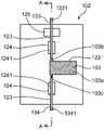
従来、薬液を患者へ注入する注入装置には、特許文献1に記載されているように使い捨てのポンプユニットを備えた注入装置がある。このような注入装置は、図25に示されるように、本体102と、使い捨てのポンプユニットであるディスポ部103とを備える。 Conventionally, there is an injection device equipped with a disposable pump unit as described in Patent Document 1 as an injection device for injecting a drug solution into a patient. Such an injection device, as shown in FIG. 25, comprises a
本体102の表面には、ディスポ部103のポンプ本体103aが配置されるディスポ部配置凹部122(以下、凹部122という)と、当該凹部122の上流側および下流側にそれぞれ延びるように形成された一対のチューブ配置溝123とが形成されている。 On the surface of the
一対のチューブ配置溝123(以下、溝123という)には、それぞれ圧力センサ124が設けられている。各圧力センサ124は、チューブの圧力変動によって動く可動ブロック1241を有する。さらに、凹部122の上流側の溝123には、気泡センサ125が設けられている。 A
ディスポ部103は、圧電素子で駆動するダイヤフラムポンプを備えたポンプ本体103aと、ポンプ本体103aの吸入口103bに接続された吸引側チューブ133と、ポンプ本体103aの吐出口103cに接続された吐出側チューブ134とを備える。 The
吸引側チューブ133は、凹部122の上流側の溝123に嵌合され、さらに、正確な圧力測定のために圧力センサ124の可動ブロック1241に設けられた溝に隙間なく嵌合される。また、吸引側チューブ133は、気泡センサ125の検知部に対向して配置される。同様に、吐出側チューブ134も、凹部122の下流側の溝123に嵌合され、圧力センサ124の可動ブロック1241に設けられた溝に隙間なく嵌合される。 The suction-
吸引側チューブ133の接続口1331には、薬剤が収容された容器に接続される。吐出側チューブ134の接続口1341には、患者側チューブが接続される。 A
上記のように構成された注入装置では、患者への薬液の注入を行う場合には、まず、使い捨てのディスポ部103を上記のようにして本体102に取り付けてから薬液の注入を行う。 In the injection device configured as described above, when injecting a liquid medicine into a patient, first, the disposable
薬液注入中において、吸引側チューブ133が折れ曲がるなどの理由により、薬液がポンプ本体103aの上流側で流れにくい場合には、上流側の圧力センサ124により吸引側チューブ133の圧力低下を検知するとともに、気泡センサ125が気泡混入の有無を検知する。これらの検知信号を受けた注入装置の制御部は、ポンプの作動停止や警報するように注入装置内の制御をする。一方、患者側に薬液が流れにくい状況が生じて薬液がポンプ本体103aの下流側で流れにくい場合には、下流側の圧力センサ124により吐出側チューブ134の圧力上昇を検知し、その検知信号を受けた制御部はポンプの作動停止や警報のための制御をする。 During chemical injection, if the chemical does not flow easily on the upstream side of the pump
特許文献1に記載されるような注入装置では、吸引側チューブ133および吐出側チューブ134は、本体102の溝123に嵌合されるとともに、これらチューブの拡大および収縮に基づいて正確に圧力測定するために、圧力センサ124の可動ブロック1241に設けられた溝に隙間なく嵌合される必要がある。また、吸引側チューブ133は、気泡センサ125の検知部に対向して配置される必要がある。そのため、これらのチューブ133、134は、圧力センサ124および気泡センサ125に密に接触することが可能なシリコーンゴムなどの軟質な材料などの特定の材料で形成される必要があり、かつ、これらチューブ133、134の管厚や管径が所定の誤差の範囲内で製造されなければならない。その結果、これらのチューブ133、134についての材質および寸法に制限があるという問題がある。 In the injection device as described in Patent Document 1, the
また、ポンプユニット103を本体102に取り付けるときにこれらのチューブ133、134を圧力センサ124および気泡センサ125に密に接触した状態で適切に取り付ける必要があるので、チューブの装着が煩わしいという問題がある。 In addition, when attaching the
本発明はかかる問題を解決するためになされたものであり、ポンプに接続される吸引側チューブおよび吐出側チューブの材質、管厚や管径などの制限を受けることなく、かつこれらのチューブの装着作業の煩わしさを解消することが可能な接続部材を提供することを目的とする。 SUMMARY OF THE INVENTION The present invention has been made to solve such problems. An object of the present invention is to provide a connection member capable of eliminating troublesome work.
本発明の接続部材は、液体を圧送するポンプの吸引口と吸引側チューブとの接続、および当該ポンプの吐出口と吐出側チューブとの接続をするために、当該ポンプとこれら吸引側チューブおよび吐出側チューブとの間に設けられる接続部材であって、前記吸引口に接続される吸引側開口と、前記吐出口に接続される吐出側開口とを有し、当該吸引口と当該吸引側開口との接続、および当該吐出口と当該吐出側開口との接続がされた状態で、前記ポンプが取り付けられるポンプ取付部と、前記吸引側チューブが接続される吸引側接続部、および前記吐出側チューブが接続される吐出側接続部を有するチューブ接続部と、前記ポンプ取付部の前記吸引側開口と前記チューブ接続部の前記吸引側接続部との間を液体の流通可能に連通する吸引路部、および前記ポンプ取付部の前記吐出側開口と前記チューブ接続部の前記吐出側接続部との間を液体の流通可能に連通する吐出路部を有する流路形成部とを備えており、前記吸引路部および前記吐出路部のそれぞれにおける少なくとも一部は、それらの内部を流通する液体の圧力によって変形可能な膜部を有しており、前記膜部が前記吸引路部および前記吐出路部の内部を流れる液体の流れの状態を前記膜部の変形によって検知するセンサに対向して配置されるように、前記流路形成部は、前記センサに対して取付可能な形状を有し、前記接続部材は、注入装置本体における前記センサを保持する装着部に装着されるものであり、かつ、前記膜部が前記センサに対向した状態で、前記装着部の被嵌合部に嵌合する嵌合部を有する、ことを特徴とする。
The connection member of the present invention is used to connect the suction port of a pump for pumping a liquid to a suction side tube and to connect the discharge port of the pump to a discharge side tube. A connection member provided between a side tube and having a suction side opening connected to the suction port and a discharge side opening connected to the discharge port, wherein the suction port and the suction side opening and the connection between the discharge port and the discharge-side opening, a pump mounting portion to which the pump is mounted, a suction-side connection portion to which the suction-side tube is connected, and the discharge-side tube are connected. a tube connecting portion having a discharge-side connecting portion to be connected, a suction path portion communicating between the suction-side opening of the pump mounting portion and the suction-side connecting portion of the tube connecting portion so that liquid can flow; a flow passage forming portion having a discharge passage portion that allows liquid to flow between the discharge side opening of the pump mounting portion and the discharge side connection portion of the tube connection portion; and at least a part of each of the discharge passage portions has a membrane portion deformable by the pressure of the liquid flowing therein, and the membrane portion causes the insides of the suction passage portion and the discharge passage portion to be deformed. The flow path forming part has a shape that can be attached to the sensor so as to face the sensor that detects the flow state of the flowing liquid by deformation of the membrane part,and the connection member is: a fitting portion that is attached to the attachment portion that holds the sensor in the injection device main body and that is fitted to the fitted portion of the attachment portion in a state in which the membrane faces the sensor; characterized byhaving
かかる構成により、チューブ接続部の吸引側接続部および吐出側接続部にそれぞれ接続される吸引側チューブおよび吐出側チューブとポンプ取付部に取り付けられるポンプの吸引口および吐出口との間は、それぞれ吸引路部および吐出路部によって液体の流通が可能になっている。吸引路部および吐出路部の少なくとも一部を構成する膜部がそれらの内部を通る液体の圧力により変形したときに、当該膜部に対向するセンサが膜部の変形によって吸引路部および吐出路部の内部を流れる液体の流れの状態を検知することが可能である。これにより、吸引側チューブおよび吐出側チューブの材質、管厚や管径などの制限を受けることなく、液体の流れの状態をセンサを用いて検知することが可能である。そのため、様々な種類のチューブを使用することが可能になる。 With such a configuration, suction is provided between the suction side tube and the discharge side tube respectively connected to the suction side connection portion and the discharge side connection portion of the tube connection portion and the suction port and the discharge port of the pump attached to the pump mounting portion. The passage and the discharge passage allow the liquid to flow. When the membranes forming at least a part of the suction path and the discharge path are deformed by the pressure of the liquid passing through them, the sensor facing the membranes is deformed so that the suction path and the discharge path are deformed. It is possible to detect the state of the flow of liquid flowing inside the unit. As a result, the state of the liquid flow can be detected using the sensor without being restricted by the materials, tube thicknesses, tube diameters, and the like of the suction-side tube and the discharge-side tube. Therefore, it becomes possible to use various kinds of tubes.
また、この構成では、吸引路部および吐出路部の膜部がセンサに対して位置決めされればセンサによって液体の流れが検知可能であるので、吸引側チューブおよび吐出側チューブをセンサに対しての相対的な位置関係を考慮することなくチューブ接続部に接続することが可能であり、これらチューブの装着作業の煩わしさが解消される。
しかも、上記の構成では、接続部材は、注入装置本体における前記センサを保持する装着部に装着されるものであり、かつ、膜部がセンサに対向した状態で、前記装着部の被嵌合部に嵌合する嵌合部を有する。この構成では、接続部材の嵌合部が注入装置本体におけるセンサを保持する装着部の被嵌合部に嵌合するだけで、前記膜部を前記センサに対向した位置に容易に位置決めすることが可能である。
In addition, in this configuration, if the film portions of the suction channel portion and the discharge channel portion are positioned with respect to the sensor, the flow of the liquid can be detected by the sensor. It is possible to connect to the tube connecting portion without considering the relative positional relationship, and the troublesome work of attaching these tubes is eliminated.
Moreover, in the above configuration, the connection member is attached to the attachment portion that holds the sensor in the injection device main body, and the attached portion of the attachment portion is attached to the attachment portion in a state in which the membrane portion faces the sensor. It has a fitting portion that fits into. With this configuration, the membrane can be easily positioned at a position facing the sensor simply by fitting the fitting portion of the connection member to the fitted portion of the mounting portion that holds the sensor in the injection device main body. It is possible.
前記流路形成部は、前記吸引路部と一体に形成され、前記ポンプの前記吸引口と前記ポンプ取付部の前記吸引側開口との間を液密的にシールする吸引側シール部と、前記吐出路部と一体に形成され、前記ポンプの前記吐出口と前記ポンプ取付部の前記吐出側開口との間を液密的にシールする吐出側シール部とを有しているのが好ましい。 The flow passage forming portion is integrally formed with the suction passage portion and liquid-tightly seals between the suction port of the pump and the suction side opening of the pump mounting portion; It is preferable to have a discharge-side seal portion that is integrally formed with the discharge path portion and that liquid-tightly seals between the discharge port of the pump and the discharge-side opening of the pump mounting portion.
かかる構成により、流路形成部が吸引側および吐出側においてそれぞれシール部を有しているので、ポンプの吸引口および吐出口における液体の漏れを防ぐことが可能である。 With such a configuration, since the flow path forming portion has seal portions on the suction side and the discharge side, respectively, it is possible to prevent liquid from leaking at the suction port and the discharge port of the pump.
しかも、吸引側および吐出側のそれぞれにおいて膜部とシール部とが一体形成されているので、部品点数の増加を防ぐことが可能である。 Moreover, since the film portion and the seal portion are integrally formed on each of the suction side and the discharge side, it is possible to prevent an increase in the number of parts.
前記吸引路部の膜部および前記吸引側シール部の組合せ、ならびに前記吐出路部の膜部および前記吐出側シール部の組合せは、それぞれ、1つの管状部材を形成しているのが好ましい。 It is preferable that the combination of the membrane portion of the suction passage portion and the suction side seal portion and the combination of the membrane portion of the discharge passage portion and the discharge side seal portion each form one tubular member.
かかる構成により、流路形成部における吸引側および吐出側において膜部およびシール部が1つの管状部材を形成しているので、管状の吸引路部および吐出路部を形成することが可能である。これにより、吸引路部および吐出路部が簡単な構成になり、かつ、吸引路部および吐出路部における円滑な液体の流れを実現することが可能である。 With such a configuration, since the film portion and the seal portion form one tubular member on the suction side and the discharge side of the flow path forming portion, it is possible to form the tubular suction passage portion and the discharge passage portion. This makes it possible to simplify the structure of the suction path portion and the ejection path portion, and to realize a smooth liquid flow in the suction path portion and the ejection path portion.
前記吸引側接続部および前記吐出側接続部が筒状であり、前記吸引側接続部の周囲を前記吸引路部の膜部が隙間をあけて覆うことにより、当該吸引側接続部と当該吸引路部の膜部との間に吸引側流路が形成され、前記吐出側接続部の周囲を前記吐出路部の膜部が隙間をあけて覆うことにより、当該吐出側接続部と当該吐出路部の膜部との間に吐出側流路が形成されているのが好ましい。 The suction-side connecting portion and the discharge-side connecting portion are cylindrical, and the suction-side connecting portion and the suction-side connecting portion are covered by the film portion of the suction path portion with a gap around the suction-side connecting portion. A suction-side flow path is formed between the discharge-side connection part and the film part of the discharge-side connection part. It is preferable that a discharge-side flow path is formed between the film portion of the
かかる構成により、吸引側チューブに接続される筒状の吸引側接続部とそれを覆う吸引路部の膜部との間に吸引側流路が形成され、かつ、吐出側チューブに接続される筒状の吐出側接続部とそれを覆う吐出路部の膜部との間に吐出側流路が形成されているので、吸引側および吐出側のいずれにおいても膜部における気泡の滞留を防ぐことが可能である。 With such a configuration, a suction-side channel is formed between the cylindrical suction-side connecting portion connected to the suction-side tube and the film portion of the suction channel portion covering it, and the tube connected to the discharge-side tube is formed. Since the discharge-side flow path is formed between the discharge-side connecting portion and the membrane of the discharge path covering it, it is possible to prevent air bubbles from accumulating in the membrane on both the suction side and the discharge side. It is possible.
前記接続部材は、前記膜部が前記センサに対向していない状態で前記嵌合部が前記被嵌合部へ嵌合することを規制する規制部を有するのが好ましい。 It is preferable that the connection member has a restricting portion that restricts the fitting portion from fitting into the fitted portion when the film portion does not face the sensor.
かかる構成により、接続部材を注入装置本体に装着するときに誤った向きに装着することを防止することが可能である。 With such a configuration, it is possible to prevent the connection member from being mounted in the wrong direction when mounting it on the injection device main body.
本発明のポンプ用ケーシングは、請求項2記載の接続部材と、前記ポンプ取付部における前記ポンプが挿入される凹部を閉じる蓋部とを備えたポンプ用ケーシングであって、前記吸引側シール部および前記吐出側シール部は、同じ高さであり、前記凹部には、前記吸引側シール部および前記吐出側シール部と同じ高さを有する少なくとも1個のポンプ固定部が設けられ、前記蓋部には、前記吸引側シール部および前記吐出側シール部、ならびに前記ポンプ固定部のそれぞれに向けて突出する突起が設けられていることを特徴とする。 A pump casing according to the present invention is a pump casing comprising the connecting member according to
かかる構成により、ポンプ取付部の凹部に挿入されるポンプを、吸引側シール部および吐出側シール部、ならびに少なくとも1個のポンプ固定部とそれぞれに対向する蓋部の突起とで挟んだ状態で少なくとも3か所で支持することが可能であり、その結果、ポンプの変形を防ぐことが可能である。 With this configuration, the pump inserted into the concave portion of the pump mounting portion is sandwiched between the suction side seal portion, the discharge side seal portion, and the at least one pump fixing portion and the protrusions of the lid portion facing each other. It is possible to support it in three places and as a result it is possible to prevent deformation of the pump.
前記ポンプ固定部は、前記ポンプ取付部に形成された開口を通して前記凹部の内側に突出しており、当該ポンプ固定部は、前記吸引側シール部および前記吐出側シール部とともに前記吸引路部および前記吐出路部と一体に形成されているのが好ましい。 The pump fixing portion protrudes inside the recess through an opening formed in the pump mounting portion. It is preferably formed integrally with the path.
かかる構成により、部品点数の増加を防ぐことが可能である。 With such a configuration, it is possible to prevent an increase in the number of parts.
前記ポンプは、液体圧送時に動かない不動部分を有しており、前記吸引口および前記吐出口は、前記不動部分に配置され、前記吸引側シール部および前記吐出側シール部、ならびに前記ポンプ固定部は、前記ポンプが前記凹部に挿入された状態で前記不動部分の一方の面に当接可能な位置に配置され、前記蓋部の前記突起は、前記ポンプが前記凹部に挿入された状態で前記不動部分の他方の面に当接可能な位置に配置されているのが好ましい。 The pump has a stationary portion that does not move when the liquid is pumped, and the suction port and the discharge port are arranged in the stationary portion, and the suction side seal portion, the discharge side seal portion, and the pump fixing portion are arranged in the stationary portion. is arranged at a position where the pump can abut against one surface of the stationary portion when the pump is inserted into the recess, and the protrusion of the lid portion is arranged in a state where the pump is inserted into the recess. It is preferably arranged at a position capable of contacting the other surface of the stationary portion.
かかる構成により、ポンプが凹部に挿入された状態では、ポンプの不動部分の一方の面に吸引側シール部および吐出側シール部、ならびにポンプ固定部が当接し、他方の面に蓋部の突起が当接することが可能である。これにより、ポンプの不動部分を吸引側シール部および吐出側シール部、ならびにポンプ固定部とそれぞれに対向する蓋部の突起とで挟んだ状態で少なくとも3か所で支持することが可能であり、その結果、ポンプの変形をより確実に防ぐことが可能である。 With this configuration, when the pump is inserted into the recess, the suction side seal portion, the discharge side seal portion, and the pump fixing portion are in contact with one surface of the stationary portion of the pump, and the projection of the lid portion is on the other surface. Abutment is possible. As a result, the stationary portion of the pump can be supported at at least three locations while being sandwiched between the suction side seal portion, the discharge side seal portion, and the projections of the lid portion facing the pump fixing portion, As a result, deformation of the pump can be prevented more reliably.
本発明の注入装置は、液体を圧送するポンプと、吸引側チューブと、吐出側チューブと、前記ポンプの吸引口と前記吸引側チューブとの接続、および当該ポンプの吐出口と前記吐出側チューブとの接続をするために、当該ポンプとこれら吸引側チューブおよび吐出側チューブとの間に設けられる接続部材であって、前記吸引口に接続される吸引側開口と、前記吐出口に接続される吐出側開口とを有し、当該吸引口と当該吸引側開口との接続、および当該吐出口と当該吐出側開口との接続がされた状態で、前記ポンプが取り付けられるポンプ取付部と、前記吸引側チューブが接続される吸引側接続部、および前記吐出側チューブが接続される吐出側接続部を有するチューブ接続部と、前記ポンプ取付部の前記吸引側開口と前記チューブ接続部の前記吸引側接続部との間を液体の流通可能に連通する吸引路部、および前記ポンプ取付部の前記吐出側開口と前記チューブ接続部の前記吐出側接続部との間を液体の流通可能に連通する吐出路部を有する流路形成部とを備えており、前記吸引路部および前記吐出路部のそれぞれにおける少なくとも一部は、それらの内部を流通する液体の圧力によって変形可能な膜部を有しており、前記膜部が前記吸引路部および前記吐出路部の内部を流れる液体の流れの状態を前記膜部の変形によって検知するセンサに対向して配置されるように、前記流路形成部は、前記センサに対して取付可能な形状を有する接続部材と、前記センサを保持するとともに前記接続部材が装着される装着部を有する注入装置本体とを備えた液体を注入対象へ注入するための注入装置であって、前記接続部材は、前記膜部が前記センサに対向した状態で、前記装着部に設けられた被嵌合部に嵌合する嵌合部を有することを特徴とする。
The injection device of the present invention comprises a pump for pumping a liquid, a suction side tube, a discharge side tube, a connection between the suction port of the pump and the suction side tube, and a discharge port of the pump and the discharge side tube. A connection member provided between the pump and the suction-side tube and the discharge-side tube in order to connect the suction-side opening connected to the suction port and the discharge port connected to the discharge port. a side opening, wherein the pump is mounted in a state in which the suction port and the suction side opening are connected and the discharge port and the discharge side opening are connected; and the suction side. a tube connection portion having a suction side connection portion to which a tube is connected and a discharge side connection portion to which the discharge side tube is connected; the suction side opening of the pump mounting portion and the suction side connection portion of the tube connection portion; and a discharge passage portion communicating between the discharge-side opening of the pump mounting portion and the discharge-side connection portion of the tube connection portion so as to allow liquid to flow. and at least a part of each of the suction path part and the discharge path part has a film part deformable by the pressure of the liquid flowing therein, The flow path forming portion is arranged so that the film portion faces a sensor that detects the state of the flow of the liquid flowing through the suction path portion and the discharge path portion by deformation of the film portion. An injection device for injecting a liquid into an injection target, comprising: a connection memberhaving a shape attachable to a sensor; The connection member has a fitting portion that fits into a fitted portion provided on the mounting portion in a state in which the film portion faces the sensor.
かかる構成により、注入装置本体の装着部にセンサが集中して配置されているので、吸引側チューブおよび吐出側チューブをポンプに接続する接続部材を装着部に装着するだけで当該接続部材に対してセンサを装着することが可能であり、いいかえれば、接続部材に対してセンサを所定の位置に正確に配置することが可能である。 With this configuration, the sensors are arranged intensively in the mounting portion of the injection device main body, so that the connection member for connecting the suction side tube and the discharge side tube to the pump is simply mounted on the mounting portion. It is possible to mount the sensor, in other words to place it precisely at a predetermined position with respect to the connecting member.
以上のように、本発明の接続部材によれば、ポンプに接続される吸引側チューブおよび吐出側チューブの材質、管厚や管径などの制限を受けることなく、かつこれらのチューブの装着作業の煩わしさを解消することができる。 As described above, according to the connection member of the present invention, there is no restriction on the materials, thicknesses, diameters, etc. of the suction side tube and the discharge side tube that are connected to the pump, and the installation work of these tubes is easy. Annoyance can be eliminated.
以下、本発明の好ましい実施形態について、図面を参照しながら説明する。 Preferred embodiments of the present invention are described below with reference to the drawings.
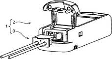
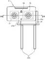
図1に示されるように、本発明の実施形態に係る注入装置1は、液体を注入対象へ注入するための装置であり、本実施形態では薬液を患者へ注入するための注入装置として携帯可能な構成を有している。注入装置1は、注入装置本体2と、使い捨てのポンプユニット3とを備える。 As shown in FIG. 1, an injection device 1 according to an embodiment of the present invention is a device for injecting a liquid into an injection target, and in this embodiment, it is portable as an injection device for injecting a drug solution into a patient. configuration. The injection device 1 comprises an injection device
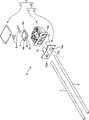
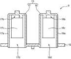
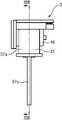
ポンプユニット3は、図2に示されるように、本発明の実施形態に係る接続部材25を含むポンプ用ケーシング5を備えた構成を有している。具体的には、ポンプユニット3は、薬液を圧送するポンプとしてのダイヤフラムポンプ4と、当該ダイヤフラムポンプ4を収納するポンプ用ケーシング5と、吸引側チューブ6と、吐出側チューブ7と、ダイヤフラムポンプ4を注入装置本体2の電気回路に電気的に接続する電極8とを備える。 The
なお、薬液を圧送するためのポンプは、上記のダイヤフラムポンプ4以外のポンプであってもよく、その場合も使い捨てできる安価なポンプが好ましい。 It should be noted that the pump for pumping the liquid medicine may be a pump other than the above-described
ダイヤフラムポンプ4は、平坦なケーシング内部にダイヤフラムおよび当該ダイヤフラムを往復振動させる圧電素子を内蔵した脈動型のポンプであり、平坦なケーシングの下面に開口する吸引口4aおよび吐出口4bを有する。 The
ポンプ用ケーシング5は、図2~8に示されるように、ケーシング本体9と、チューブ接続部10と、蓋部11とを備える。ケーシング本体9およびチューブ接続部10は、本発明の実施形態である接続部材25を構成する。接続部材25は、ダイヤフラムポンプ4の吸引口4aと吸引側チューブ6との接続、および当該ポンプ4の吐出口4bと吐出側チューブ7との接続をするために、当該ポンプ4とこれら吸引側チューブ6および吐出側チューブ7との間に設けられる。 The
チューブ接続部10は、ケーシング本体9の前面9a側に取り付けられている。チューブ接続部10は、吸引側チューブ6および吐出側チューブ7がそれぞれ接続される構成を有する。具体的には、チューブ接続部10は、吸引側チューブ6に接続される吸引側接続部14と、吐出側チューブ7に接続される吐出側接続部15とを有している。吸引側接続部14および吐出側接続部15は、円筒形状をしており、チューブ接続部10の前面フランジ10aと一体形成されている。吸引側接続部14および吐出側接続部15は、それぞれ、前面側のチューブ接続口14a、15aと、奥端側の開口14b、15bとを有する。吸引側チューブ6および吐出側チューブ7は、それぞれチューブ接続口14a、15aに挿入されて接着剤などで固定される。 The
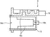
ケーシング本体9は、図9~17に示されるように、ポンプ取付部12と、流路形成部13とを備えている。 The casing
ポンプ取付部12は、その上面においてダイヤフラムポンプ4が取り付けられる凹部12aを有する。ダイヤフラムポンプ4は、凹部12a内部に収納され、蓋部11をケーシング本体9に溶接や接着などを行うことによって凹部12aの内部に固定される。なお、ダイヤフラムポンプ4の固定についての詳細は、後述の(本実施形態の特徴)(7)に記載されている。凹部12aが蓋部11(図2~6参照)によって閉じられることにより、ダイヤフラムポンプ4は外部の異物や水分などから保護される。凹部12aの底壁において、ダイヤフラムポンプ4の吸引口4aおよび吐出口4b(図2参照)に対応する位置に吸引側開口12bおよび吐出側開口12cが形成されている。それらの吸引側開口12bおよび吐出側開口12cの内部には、それぞれ、流路形成部13側の後述の吸引側接続口20および吸引側シール部22、ならびに吐出側接続口21および吐出側シール部23が、上記のダイヤフラムポンプ4の吸引口4aおよび吐出口4bに対向するように配置されている。このようなポンプ取付部12の構成により、ダイヤフラムポンプ4の吸引口4aと吸引側開口12bとの接続、およびダイヤフラムポンプ4の吐出口4bと吐出側開口12cとの接続がされた状態で、ダイヤフラムポンプ4は、ポンプ取付部12の凹部12aに取り付けられる。
The
ポンプ取付部12は、硬質の合成樹脂など変形しにくい材料で製造されているのが好ましい。その場合、ポンプユニット3を注入装置本体2に装着した時に流路形成部13(とくに吸引路部16および吐出路部17の膜部16a、17a)が注入装置本体2の後述の気泡センサ37および閉塞センサ38(図18~24参照)に対向する位置に正確に位置決めすることが可能になる。 The
ポンプ取付部12の形状は、注入装置本体2の後述のポンプ装着部33のうち凸部34よりも上方の空間33b(図18~19参照)に挿入可能な形状を有している。また、ポンプ取付部12の奥側端部には、後述の規制部12dが設けられている。 The shape of the
流路形成部13は、吸引路部16および吐出路部17を有する。吸引路部16は、ダイヤフラムポンプ4の吸引口4aとチューブ接続部10の吸引側接続部14との間を薬液の流通可能に連通する構成を有する。吐出路部17は、ダイヤフラムポンプ4の吐出口4bとチューブ接続部10の吐出側接続部15との間を薬液の流通可能に連通する構成を有する。 The flow
具体的には、本実施形態の吸引路部16および吐出路部17は、それぞれ矩形筒状をしており、前面側の開口16d、17dを有しており、後面側は閉じている。 Specifically, the
吸引路部16および吐出路部17のそれぞれにおける少なくとも一部は、それらの内部を流通する薬液の圧力によって変形可能な膜部16a、17aを有している。本実施形態では、吸引路部16および吐出路部17は、シリコーンゴムなどの変形可能な軟質の材料で一体成形により製造されている。したがって、シリコーンゴム製の矩形筒状の吸引路部16および吐出路部17は、両側の側壁だけでなく全周の壁が変形可能な膜部16a、17aになっている。なお、吸引路部16および吐出路部17は、両側の側壁だけ変形可能な膜部16a、17aにしてもよい。 At least a part of each of the
膜部16a、17aが吸引路部16および吐出路部17の内部を流れる薬液の流れの状態を膜部16a、17aの変形によって検知するセンサ、本実施形態では気泡センサ37および閉塞センサ38(図18~24参照)、に対向して配置されるように、流路形成部13は、これら気泡センサ37および閉塞センサ38に対向して取付可能な形状を有する。具体的には、吸引路部16および吐出路部17の側壁を構成する膜部16a、17aは、互いに離間して外部に露出している。図18~24に示されるように、吸引路部16および吐出路部17が、それぞれ注入装置本体2のポンプ装着部33の吸引路部挿入空間35および吐出路部挿入空間36に挿入された状態では、吸引路部16の膜部16aは、気泡センサ37の一対の圧電素子37a、37bの間に配置される(図24参照)。また、吐出路部17の側壁は、閉塞センサ38に当接しており(図19参照)、吐出路部17の側壁は、図7~8に示されるように膜部17aで構成されている。
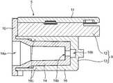
流路形成部13は、図8~9および図14~17に示されるように、ダイヤフラムポンプ4の吸引口4aと吸引路部16とを連通する吸引側接続口20と、ダイヤフラムポンプ4の吐出口4bと吐出路部17とを連通する吐出側接続口21とを有する。さらに、吸引側接続口20の周囲には、ダイヤフラムポンプ4の吸引口4aとポンプ取付部12の吸引側開口12bとの間を液密的にシールする吸引側シール部22が設けられている。また、吐出側接続口21の周囲には、ダイヤフラムポンプ4の吐出口4bとポンプ取付部12の吐出側開口12cとの間を液密的にシールする吐出側シール部23が設けられている。上記のように、吸引側接続口20および吸引側シール部22は、ポンプ取付部12の吸引側開口12bを通して、ダイヤフラムポンプ4の吸引口4aに接続される。また、吐出側接続口21および吐出側シール部23は、ポンプ取付部12の吐出側開口12cを通して、ダイヤフラムポンプ4の吐出口4bに接続される。 8 to 9 and FIGS. 14 to 17, the flow
吸引路部16の膜部16aおよび吸引側シール部22の組合せ、ならびに吐出路部17の膜部17aおよび吐出側シール部23の組合せは、それぞれ、可撓性を有する材料、例えば上記のシリコーンゴムなどの材料で一体成形されている。 The combination of the
さらに、吸引路部16の膜部16aおよび吸引側シール部22の組合せ、ならびに吐出路部17の膜部17aおよび吐出側シール部23の組合せは、それぞれ、1つの管状部材(本実施形態では、矩形の筒状体)を形成している。 Furthermore, the combination of the
上記のチューブ接続部10の円筒状の吸引側接続部14(図2~7参照)は、矩形筒状の吸引路部16の前面側の開口16dから吸引路部16内部に挿入され、上下両側から支持部16c(図5~6、図10~14参照)で支持される。このように配置されることにより、吸引側接続部14の周囲を吸引路部16の膜部16aが隙間をあけて覆うことにより、当該吸引側接続部14と当該吸引路部16の膜部16aとの間に吸引側流路18(図7~8および図24参照)が形成される。 The cylindrical suction side connection portion 14 (see FIGS. 2 to 7) of the
吸引側流路18は、吸引路部16の連通路16bを介して吸引側接続部14の開口14bに連通している(図7参照)。また、吸引側流路18は、上記の吸引側接続口20を介してダイヤフラムポンプ4の吸引口4aに接続されている。 The suction-
上記の吸引側接続部14と同様に、円筒状の吐出側接続部15は、矩形形状の吐出路部17の前面側の開口17dから吐出路部17内部に挿入され、上下両側から支持部17c(図10および図13~14参照)で支持される。このように配置されることにより、吐出側接続部15の周囲を吐出路部17の膜部17aが隙間をあけて覆うことにより、当該吐出側接続部15と当該吐出路部17の膜部17aとの間に吐出側流路19(図7~8参照)が形成される。 Similar to the suction
吐出側流路19は、吐出路部17の連通路17bを介して吐出側接続部15の開口15bに連通している(図7参照)。また、吐出側流路19は、上記の吐出側接続口21を介してダイヤフラムポンプ4の吐出口4bに接続されている。 The discharge-
したがって、本実施形態のポンプユニット3では、吸引側チューブ6から吸引された薬液は、吸引側接続部14の開口14b、吸引路部16の連通路16b、吸引側流路18、吸引側接続口20を順に流れて、ダイヤフラムポンプ4の吸引口4aから当該ポンプ4の内部に導入される。 Therefore, in the
また、ダイヤフラムポンプ4の吐出口4bから吐出された薬液は、吐出側接続口21、吐出側流路19、吐出路部17の連通路17b、吐出側接続部15の開口15bを順に流れて、吐出側チューブ7から吐出される。 Further, the chemical liquid discharged from the
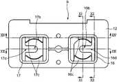
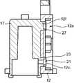
流路形成部13は、図7~8に示されるように、吸引路部16と吐出路部17との間において、ポンプ用ケーシング5が装着される注入装置本体2に形成された被嵌合部である凸部34(図18~20および図22参照)に嵌合する嵌合部として間隙13aを有する。いいかえれば、流路形成部13を含むケーシング本体9で形成される接続部材25(図2参照)は、膜部16a、17aが気泡センサ37および閉塞センサ38に対向した状態で、これらのセンサ37、38を保持する注入装置本体2の凸部34(被嵌合部)に嵌合する間隙13a(嵌合部)を有する。 As shown in FIGS. 7 and 8, the flow
また、ポンプ取付部12は、流路形成部13の膜部16a、17aが気泡センサ37および閉塞センサ38に対向していない状態で上記の間隙13a(嵌合部)が上記の凸部34(被嵌合部)へ嵌合することを規制する規制部12dを有する。規制部12dは、ポンプ取付部12の奥側端部において、上記の間隙13aの上方を塞ぐ形状をしている。規制部12dは、ポンプ用ケーシング5が天地逆で注入装置本体2のポンプ装着部33に装着されようとしたときには、凸部34に当たることにより、流路形成部13の膜部16a、17aが気泡センサ37および閉塞センサ38に対向していない状態での上記の間隙13aが上記の凸部34へ嵌合することを規制する。 In addition, the
なお、ポンプ用ケーシング5が正しい向きにポンプ装着部33に装着されるときには、ポンプ取付部12の規制部12dは、凸部34の上方の空間33bに挿入されるので、膜部16a、17aが気泡センサ37および閉塞センサ38に対向した状態での上記の間隙13aが上記の凸部34へ嵌合することが可能である。 When the
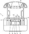
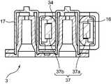
注入装置本体2は、図18~19に示されるように、本体ケース31と、カバー32と、ポンプ装着部33と、凸部34と、気泡センサ37と、閉塞センサ38とを有する。 The injection device
ポンプ装着部33は、本体ケース31の内部に形成され、ポンプユニット3のポンプ用ケーシング5が装着される空間部である。ポンプ装着部33の入口は、カバー32によって開閉自在に閉じられる。ポンプ装着部33の底壁33a(図18参照)には、凸部34(被嵌合部)が底壁33aから上方に突出するように配置されている。ポンプ装着部33における凸部34の両側には、上記の吸引路部挿入空間35および吐出路部挿入空間36が形成され、これらの空間35、36には、吸引路部16および吐出路部17が離間して個別に収容される。 The
気泡センサ37は、図18~24に示されるように、互いに離間して配置された一対の圧電素子37a、37bと、リード線37cと、基板37dとを有する。気泡センサ37の一対の圧電素子37a、37bは、ポンプ装着部33に配置されている。具体的には、一方の圧電素子37bは、凸部34の内部に収容されている。他方の圧電素子37aは、吸引路部16が挿入される吸引路部挿入空間35を介して凸部34に対向している位置に配置されている。 The
一対の圧電素子37a、37bは、それぞれ基板37dおよびリード線37cを介して注入装置本体2の電気回路に電気的に接続されている。一対の圧電素子37a、37bは、一方が超音波からなる入力波を発信する発信部、他方が吸引路部16を通過した超音波を受信する受信部として機能する。一対の圧電素子37a、37b間で伝えられる超音波は、これらの素子間の空気密度によって強度等が変動する。したがって、薬液が流れなくなった吸引路部16の膜部16aが凹むことにより、膜部16aとこれら圧電素子37a、37bとの間に空隙が生じたときには、一対の圧電素子37a、37bを有する気泡センサ37は、伝搬される超音波の強度等の変化によって、吸引路部16に薬液が流れなくなっていることを検知することが可能である。 The pair of
閉塞センサ38は、図18~19に示されるように、吐出路部17が挿入される吐出路部挿入空間36を介して凸部34に対向している位置に配置されている。閉塞センサ38は、吐出路部17の側壁を構成する膜部17a(図7~8参照)に当接することが可能な位置に配置されている。 As shown in FIGS. 18 and 19, the
すなわち、上記のポンプ装着部33は、気泡センサ37および閉塞センサ38を保持するとともに接続部材25(ケーシング本体9およびチューブ接続部10を組み合せたもの)が装着される本発明の「装着部」として機能する。 That is, the
以上のように構成された注入装置1では、本実施形態の接続部材25を含むポンプ用ケーシング5を用いることにより、以下のように薬液の存在を確認する薬液確認方法を実行することが可能である。 In the injection device 1 configured as described above, by using the
まず、薬液を患者へ注入する前の準備工程として、ポンプ用ケーシング5のポンプ取付部12にダイヤフラムポンプ4を取り付け、かつ、チューブ接続部10の吸引側接続部14および吐出側接続部15にそれぞれに吸引側チューブ6および吐出側チューブ7を取り付けることにより、ポンプユニット3を組み立てる。ついで、組み立てられたポンプユニット3を注入装置本体2へ取り付けることにより、接続部材25を含むポンプ用ケーシング5を、空気の存在を検出するための気泡センサ37が吸引路部16の膜部16aに対向する位置になるように配置して準備する。具体的には、気泡センサ37の一対の圧電素子37a、37bと膜部16aが対向するように、吸引路部16をポンプ装着部33の吸引路部挿入空間35に挿入する。それとともに、閉塞センサ38と吐出路部17の膜部17aとが当接するように、吐出路部17をポンプ装着部33の吐出路部挿入空間36に挿入する。 First, as a preparatory step before injecting the drug solution into the patient, the
ついで、吸引側チューブ6に薬液容器を接続し、吐出側チューブ7に患者側チューブを接続した後、注入装置1を用いて、患者へ薬液の注入を行う。このとき、注入装置1では、ダイヤフラムポンプ4がポンプ用ケーシング5の接続部材25を介して吸引側チューブ6から吐出側チューブ7へ薬液を圧送する。その状態で、吸引側チューブ6が折れ曲がるなどの理由によって吸引路部16の内部に薬液が無くなったときに、膜部16aが凹むことによって生じる膜部16aと気泡センサ37との間隙の空気を気泡センサ37で検出することによって、薬液が無いことを検知する。この検知信号に基づいて、注入装置本体2の内部の制御部は、ダイヤフラムポンプ4の作動を停止したり、警報を発する制御を行う。
Next, after connecting a drug solution container to thesuction side tube 6 and connecting a patient side tube to the discharge side tube 7, the injection device 1 is used to inject the drug solution into the patient. At this time, in the injection device 1 , the
また、患者側で薬液が流れにくい状況が発生して患者側ライン(すなわち、吐出路部17の下流側の経路)で閉塞が生じると、吐出路部17の膜部17aが膨張し、閉塞センサ38は膜部17aの圧力が上昇したことを検知する。この検知信号に基づいて、注入装置本体2の内部の制御部は、ダイヤフラムポンプ4の作動を停止したり、警報を発する制御を行う。 In addition, when a patient side line (that is, a path on the downstream side of the discharge passage portion 17) is clogged due to a situation in which it is difficult for the drug solution to flow, the
(本実施形態の特徴)
(1)
本実施形態の接続部材25は、ポンプ用ケーシング5に含まれている。この接続部材25は、吸引側チューブ6および吐出側チューブ7がそれぞれ接続されるチューブ接続部10とは別に、流路形成部13を備えている。流路形成部13は、ダイヤフラムポンプ4の吸引口4aと吸引側チューブ6が接続されるチューブ接続部10の吸引側接続部14との間を薬液の流通可能に連通する吸引路部16、およびダイヤフラムポンプ4の吐出口4bと吐出側チューブ7が接続されるチューブ接続部10の吐出側接続部15との間を薬液の流通可能に連通する吐出路部17を有している。吸引路部16および吐出路部17のそれぞれにおける少なくとも一部は、それらの内部を流通する薬液の圧力によって変形可能な膜部16a、17aを有している。これらの膜部16a、17aが吸引路部16および吐出路部17の内部を流れる薬液の流れの状態を膜部16a、17aの変形によって検知する気泡センサ37および閉塞センサ38に対向して配置されるように、流路形成部13は、気泡センサ37および閉塞センサ38に対して取付可能な形状を有する。(Features of this embodiment)
(1)
The
以上の構成では、チューブ接続部10の吸引側接続部14および吐出側接続部15にそれぞれ接続される吸引側チューブ6および吐出側チューブ7とポンプ取付部12に取り付けられるダイヤフラムポンプ4の吸引口4aおよび吐出口4bとの間は、それぞれ吸引路部16および吐出路部17によって薬液の流通が可能になっている。吸引路部16および吐出路部17の少なくとも一部を構成する膜部16a、17aがそれらの内部を通る薬液の圧力により変形したときに、当該膜部16a、17aに対向する気泡センサ37および閉塞センサ38が膜部16a、17aの変形によって吸引路部16および吐出路部17の内部を流れる薬液の流れの状態を検知することが可能である。これにより、吸引側チューブ6および吐出側チューブ7の材質、管厚や管径などの制限を受けることなく、薬液の流れの状態を気泡センサ37および閉塞センサ38を用いて検知することが可能である。そのため、様々な種類のチューブを使用することが可能になる。したがって、吸引側チューブ6および吐出側チューブ7として、変形しにくい材料または管厚のチューブを用いることが可能になり、チューブの折れ曲がりを抑制することが可能になる。 In the above configuration, the
また、この構成では、吸引路部16および吐出路部17の膜部16a、17aが気泡センサ37および閉塞センサ38に対して位置決めされれば気泡センサ37および閉塞センサ38によって薬液の流れの状態が検知可能であるので、吸引側チューブ6および吐出側チューブ7を気泡センサ37および閉塞センサ38に対しての相対的な位置関係を考慮することなくチューブ接続部10に接続することが可能であり、これらチューブの装着作業の煩わしさが解消される。 Further, in this configuration, if the
(2)
また、本実施形態の接続部材25では、流路形成部13は、吸引路部16と一体に形成され、ダイヤフラムポンプ4の吸引口4aとポンプ取付部12の吸引側開口12bとの間を液密的にシールする吸引側シール部22と、吐出路部17と一体に形成され、ダイヤフラムポンプ4の吐出口4bとポンプ取付部12の吐出側開口12cとの間を液密的にシールする吐出側シール部23とを有している。
(2)
In addition, in the
このような構成により、流路形成部13が吸引側および吐出側においてそれぞれシール部22、23を有しているので、ダイヤフラムポンプ4の吸引口4aおよび吐出口4bにおける薬液の漏れを防ぐことが可能である。 With such a configuration, the
しかも、吸引側および吐出側のそれぞれにおいて膜部16a、17aとシール部22、23とが可撓性を有する材料(例えばシリコーンゴムなど)で一体形成されているので、部品点数の増加を防ぐことが可能である。 Moreover, since the
(3)
さらに、本実施形態の接続部材25では、吸引路部16の膜部16aおよび吸引側シール部22の組合せ、ならびに吐出路部17の膜部17aおよび吐出側シール部23の組合せは、それぞれ、1つの管状部材を形成している。そのため、管状の吸引路部16および吐出路部17を形成することが可能である。これにより、吸引路部16および吐出路部17が簡単な構成になり、かつ、吸引路部16および吐出路部17における円滑な薬液の流れを実現することが可能である。(3)
Furthermore, in the connecting
(4)
さらに、本実施形態の接続部材25では、チューブ接続部10は、吸引側チューブ6に接続される筒状の吸引側接続部14と、吐出側チューブ7に接続される筒状の吐出側接続部15とを有している。吸引側接続部14とそれを覆う吸引路部16の膜部16aとの間に吸引側流路18が形成されている。吐出側接続部15とそれを覆う吐出路部17の膜部17aとの間に吐出側流路19が形成されている。そのため、吸引側および吐出側のいずれにおいても膜部16a、17aにおける気泡の滞留を防ぐことが可能である。(4)
Furthermore, in the
(5)
上記実施形態の接続部材25は、膜部16a、17aが気泡センサ37および閉塞センサ38に対向した状態で、これらセンサ37、38を保持する注入装置本体2の凸部34(被嵌合部)に嵌合する間隙13a(嵌合部)を有する。(5)
The connecting
かかる構成により、接続部材25の間隙13a(嵌合部)が注入装置本体2の凸部34(被嵌合部)に嵌合するだけで、膜部16a、17aを上記のセンサ37、38に対向した位置に容易に位置決めすることが可能である。 With such a configuration, the
(6)
さらに、本実施形態の接続部材25は、膜部16a、17aが気泡センサ37および閉塞センサ38に対向していない状態で間隙13a(嵌合部)が凸部34(被嵌合部)へ嵌合することを規制する規制部12dを有する。そのため、ポンプ用ケーシング5(とくにそれに含まれる接続部材25)を注入装置本体2に装着するときに誤った向きに装着することを防止することが可能である。具体的には、ポンプ用ケーシング5を天地逆にポンプ装着部33(図18~19参照)に装着しようとしても、凸部34がケーシング本体9のポンプ取付部12の奥側端部に設けられた規制部12d(図8~9参照)に干渉して当該ケーシング5の誤装着を確実に防止することができる。
(6)
Furthermore, in the connecting
(7)
本実施形態のポンプ用ケーシング5は、図2~3、図9、および図15~17に示されるように、上記の接続部材25と、ポンプ取付部12におけるダイヤフラムポンプ4が挿入される矩形形状の凹部12aを閉じる蓋部11とを備えている。なお、凹部12aは、本発明では矩形形状に限定されるものではなく、矩形形状以外の形状でもよい。(7)
As shown in FIGS. 2 to 3, 9, and 15 to 17, the
吸引側シール部22および吐出側シール部23は、同じ高さであり、凹部12aの一方の対角線上に配置されている。なお、吸引側シール部22および吐出側シール部23は、本発明では凹部12aの一方の対角線上に配置されていることに限定されるものではなく、他の配置でもよい。 The suction
凹部12aの他方の対角線上には、吸引側シール部22および吐出側シール部23と同じ高さを有する一対のポンプ固定部26、27が設けられている。なお、本発明では少なくとも1個のポンプ固定部が設けられていればよく、さらに凹部12aの他方の対角線上に配置されることに限定されない。 A pair of
これらの吸引側シール部22および吐出側シール部23、ならびに一対のポンプ固定部26、27は、図9および図15に示されるように、正方形をなすように配置されている。 These suction
蓋部11には、図3に示されるように、吸引側シール部22および吐出側シール部23、ならびに一対のポンプ固定部26、27のそれぞれに向けて突出する突起11aが設けられている。すなわち、突起11aは、上記の各シール部22、23ならびに一対のポンプ固定部26、27に対応する位置において、蓋部11の下面から下方に突出している。 As shown in FIG. 3, the
ポンプ用ケーシング5が上記の構成を有することにより、ポンプ取付部12の凹部12aに挿入されるダイヤフラムポンプ4を、吸引側シール部22および吐出側シール部23、ならびに少なくとも1個(本実施形態では一対)のポンプ固定部26、27とそれぞれに対向する蓋部11の突起11aとで挟んだ状態で少なくとも3か所で支持することが可能である(本実施形態では、ダイヤフラムポンプ4を上下方向から4点で支持することが可能である)。その結果、ダイヤフラムポンプ4の変形を防ぐことが可能である。
Since the
(8)
本実施形態のポンプ用ケーシング5では、図9および図15~17に示されるように、ポンプ固定部26、27は、ポンプ取付部12に形成された開口12e、12fを通して凹部12aの内側に突出している。これらのポンプ固定部26、27は、吸引側シール部22および吐出側シール部23とともに吸引路部16および吐出路部17と(シリコーンゴムなどによって)一体に形成されている。かかる構成により、部品点数の増加を防ぐことが可能である。(8)
In the
(9)
本実施形態では、図2に示されるように、ダイヤフラムポンプ4は、液体圧送時に動かない不動部分4c(具体的には、フレーム部分)と、動く部分4d(具体的には、上下に膨張および収縮をするダイヤフラム部分)とを有している。ダイヤフラムポンプ4の吸引口4aおよび吐出口4bは、不動部分4cに配置されている。一方、ポンプ用ケーシング5では、図9および図15に示されるように、吸引側シール部22および吐出側シール部23、ならびにポンプ固定部26、27は、ダイヤフラムポンプ4がポンプ取付部12の凹部12aに挿入された状態で不動部分4cの一方の面(本実施形態では下面)に当接可能な位置に配置されている。さらに、蓋部11の突起11aは、図3に示されるように、ダイヤフラムポンプ4が前記凹部12aに挿入された状態で不動部分4cの他方の面(本実施形態では上面)に当接可能な位置に配置されている。(9)
In this embodiment, as shown in FIG. 2, the
かかる構成により、ダイヤフラムポンプ4が凹部12aに挿入された状態では、ダイヤフラムポンプ4の不動部分4cの一方の面(下面)に吸引側シール部22および吐出側シール部23、ならびに一対のポンプ固定部26、27が当接し、他方の面(上面)に蓋部11の突起11aが当接することが可能である。これにより、ダイヤフラムポンプ4の不動部分4cを吸引側シール部22および吐出側シール部23、ならびに一対のポンプ固定部26、27とそれぞれに対向する蓋部の突起とで挟んだ状態で少なくとも3か所(本実施形態では4か所)で支持することが可能である。その結果、ダイヤフラムポンプ4の変形をより確実に防ぐことが可能である。 With such a configuration, when the
とくに本実施形態では、吸引側シール部22および吐出側シール部23、ならびに一対のポンプ固定部26、27は、正方形をなすように2つの対角線上に配置されているので、正方形形状のダイヤフラムポンプ4の不動部分4cの四角を安定して支持することが可能である。
In particular, in this embodiment, the suction
(10)
本実施形態の注入装置1は、薬液を圧送するダイヤフラムポンプ4と、吸引側チューブ6と、吐出側チューブ7と、上記実施形態の接続部材25を含むポンプ用ケーシング5と、ポンプ用ケーシング5が装着されるポンプ装着部33(装着部)を有する注入装置本体2とを備えている。接続部材25は、膜部16a、17aが気泡センサ37および閉塞センサ38に対向した状態で、これらセンサ37、38を保持する注入装置本体2の凸部34(被嵌合部)に嵌合する間隙13a(嵌合部)を有する。(10)
The injection device 1 of this embodiment includes a
このような注入装置1の構成では、注入装置本体2のポンプ装着部33(装着部)に気泡センサ37および閉塞センサ38が集中して配置されているので、吸引側チューブ6および吐出側チューブ7をダイヤフラムポンプ4に接続する接続部材25を含むポンプ用ケーシング5をポンプ装着部33に装着するだけで当該接続部材25に対して気泡センサ37および閉塞センサ38を装着することが可能であり、いいかえれば、接続部材25に対して気泡センサ37および閉塞センサ38を所定の位置に正確に配置することが可能である。 In the configuration of the injection device 1 as described above, the
なお、上記の実施形態では、吸引路部16および吐出路部17の内部を流れる薬液(液体)の流れの状態を膜部16a、17aの変形によって検知するセンサの一例として、気泡センサ37および閉塞センサ38を例に挙げて説明しているが、本発明はこれに限定されるものではない。本発明では、吸引路部16および吐出路部17の膜部16a、17aの変形によって液体の流れの状態を検知するセンサであれば他の種類のセンサであってもよい。 In the above-described embodiment, the
(11)
本実施形態の接続部材25を含むポンプ用ケーシング5を用いた薬液確認方法では、2つの工程(a)、(b)すなわち、
(a)ポンプ取付部12にダイヤフラムポンプ4を取り付け、かつ、チューブ接続部10の吸引側接続部14および吐出側接続部15にそれぞれに吸引側チューブ6および吐出側チューブ7を取り付けた状態で、接続部材25を含むポンプ用ケーシング5を空気の存在を検出するための気泡センサ37が吸引路部16の膜部16aに対向する位置になるように配置して準備する工程と、
(b)ダイヤフラムポンプ4が接続部材25を含むポンプ用ケーシング5を介して吸引側チューブ6から吐出側チューブ7へ薬液を圧送した状態で、吸引路部16の内部に薬液が無くなったときに、膜部16aが凹むことによって生じる膜部16aと気泡センサ37との間隙の空気を気泡センサ37で検出することによって、薬液が無いことを検知する工程とを有する。(11)
In the method for confirming a chemical solution using the
(a) With the
(b) When the
このような液体確認方法では、空気の存在を検出するための気泡センサ37などのセンサを用いて膜部16aと気泡センサ37との間隙の空気を検出することによって吸引路部16の内部を流れる薬液が無くなったことを簡易にかつ正確に検知することが可能であり、圧力センサや流量センサなどの高価なセンサが不要になる。 In such a liquid confirmation method, a sensor such as the
1 注入装置
2 注入装置本体
3 ポンプユニット
4 ダイヤフラムポンプ(ポンプ)
4c 不動部分
5 ポンプ用ケーシング
6 吸引側チューブ
7 吐出側チューブ
10 チューブ接続部
11 蓋部
11a 突起
12 ポンプ取付部
12a 凹部
13 流路形成部
13a 間隙(嵌合部)
14 吸引側接続部
15 吐出側接続部
16 吸引路部
16a 膜部
17 吐出路部
17a 膜部
18 吸引側流路
19 吐出側流路
22 吸引側シール部
23 吐出側シール部
25 接続部材
26、27 ポンプ固定部
33 ポンプ装着部(装着部)
34 凸部
37 気泡センサ(センサ)
38 閉塞センサ(センサ)1
4c
14 Suction
34
38 occlusion sensor (sensor)
Claims (10)
Translated fromJapanese前記吸引口に接続される吸引側開口と、前記吐出口に接続される吐出側開口とを有し、当該吸引口と当該吸引側開口との接続、および当該吐出口と当該吐出側開口との接続がされた状態で、前記ポンプが取り付けられるポンプ取付部と、
前記吸引側チューブが接続される吸引側接続部、および前記吐出側チューブが接続される吐出側接続部を有するチューブ接続部と、
前記ポンプ取付部の前記吸引側開口と前記チューブ接続部の前記吸引側接続部との間を液体の流通可能に連通する吸引路部、および前記ポンプ取付部の前記吐出側開口と前記チューブ接続部の前記吐出側接続部との間を液体の流通可能に連通する吐出路部を有する流路形成部と
を備えており、
前記吸引路部および前記吐出路部のそれぞれにおける少なくとも一部は、それらの内部を流通する液体の圧力によって変形可能な膜部を有しており、
前記膜部が前記吸引路部および前記吐出路部の内部を流れる液体の流れの状態を前記膜部の変形によって検知するセンサに対向して配置されるように、前記流路形成部は、前記センサに対して取付可能な形状を有し、
前記接続部材は、注入装置本体における前記センサを保持する装着部に装着されるものであり、かつ、前記膜部が前記センサに対向した状態で、前記装着部の被嵌合部に嵌合する嵌合部を有する、
ことを特徴とする接続部材。Provided between the pump and the suction-side and discharge-side tubes to connect the suction port and the suction-side tube of the pump that pressure-feeds the liquid, and to connect the discharge port and the discharge-side tube of the pump. A connecting member comprising:
It has a suction side opening connected to the suction port and a discharge side opening connected to the discharge port, the connection between the suction port and the suction side opening, and the connection between the discharge port and the discharge side opening. a pump mounting portion to which the pump is mounted in a connected state;
a tube connection portion having a suction-side connection portion to which the suction-side tube is connected and a discharge-side connection portion to which the discharge-side tube is connected;
a suction path portion that allows liquid to flow between the suction side opening of the pump mounting portion and the suction side connecting portion of the tube connecting portion; and the discharge side opening of the pump mounting portion and the tube connecting portion. a flow path forming portion having a discharge path portion that communicates with the discharge side connection portion of so that the liquid can flow,
at least a part of each of the suction passage portion and the discharge passage portion has a membrane portion deformable by the pressure of the liquid flowing therein;
The flow path forming portion is arranged so that the film portion faces a sensor that detects the state of the flow of the liquid flowing through the suction path portion and the discharge path portion by deformation of the film portion. Ithas a shape that can be attached to the sensor,
The connection member is attached to the attachment portion holding the sensor in the injection device main body, and is fitted to the fitted portion of the attachment portion in a state in which the membrane faces the sensor. having a fitting portion;
A connection member characterized by:
前記嵌合部は、前記吸引路部と前記吐出路部との間に形成され、前記凸部に嵌合する間隙である The fitting portion is a gap formed between the suction path portion and the discharge path portion and fitted to the convex portion.
請求項1に記載の接続部材。The connecting member according to claim 1.
前記吸引路部と一体に形成され、前記ポンプの前記吸引口と前記ポンプ取付部の前記吸引側開口との間を液密的にシールする吸引側シール部と、
前記吐出路部と一体に形成され、前記ポンプの前記吐出口と前記ポンプ取付部の前記吐出側開口との間を液密的にシールする吐出側シール部と
を有している、
請求項1または2に記載の接続部材。The flow path forming portion is
a suction side seal portion formed integrally with the suction path portion and liquid-tightly sealing between the suction port of the pump and the suction side opening of the pump mounting portion;
a discharge-side seal portion integrally formed with the discharge passage portion for liquid-tightly sealing between the discharge port of the pump and the discharge-side opening of the pump mounting portion;
3. The connecting member according to claim 1or 2 .
請求項3に記載の接続部材。The combination of the membrane portion of the suction passage portion and the suction side seal portion and the combination of the membrane portion of the discharge passage portion and the discharge side seal portion each form one tubular member,
The connection member according to claim3 .
前記吸引側接続部の周囲を前記吸引路部の膜部が隙間をあけて覆うことにより、当該吸引側接続部と当該吸引路部の膜部との間に吸引側流路が形成され、
前記吐出側接続部の周囲を前記吐出路部の膜部が隙間をあけて覆うことにより、当該吐出側接続部と当該吐出路部の膜部との間に吐出側流路が形成されている、
請求項1~4のいずれか1項に記載の接続部材。the suction side connection portion and the discharge side connection portion are cylindrical,
A suction-side channel is formed between the suction-side connection portion and the film portion of the suction path portion by covering the periphery of the suction-side connection portion with the film portion of the suction path portion with a gap,
A discharge-side flow path is formed between the discharge-side connection portion and the film portion of the discharge path portion by covering the periphery of the discharge-side connection portion with a gap between the film portion of the discharge passage portion. ,
The connection member according to any one of claims1-4 .
請求項1~4のいずれか1項に記載の接続部材。The connecting member has a restricting portion that restricts the fitting portion from fitting into the fitted portion when the film portion does not face the sensor.
The connecting member according toany one of claims 1-4 .
前記ポンプ取付部における前記ポンプが挿入される凹部を閉じる蓋部と
を備えたポンプ用ケーシングであって、
前記吸引側シール部および前記吐出側シール部は、同じ高さであり、
前記凹部には、前記吸引側シール部および前記吐出側シール部と同じ高さを有する少なくとも1個のポンプ固定部が設けられ、
前記蓋部には、前記吸引側シール部および前記吐出側シール部、ならびに前記ポンプ固定部のそれぞれに向けて突出する突起が設けられている、
ポンプ用ケーシング。A connecting member according to claim3 ;
A pump casing comprising a lid portion that closes a recess in the pump mounting portion into which the pump is inserted,
the suction side seal portion and the discharge side seal portion have the same height,
The concave portion is provided with at least one pump fixing portion having the same height as the suction side seal portion and the discharge side seal portion,
The lid portion is provided with projections projecting toward the suction side seal portion, the discharge side seal portion, and the pump fixing portion, respectively.
Casing for pump.
当該ポンプ固定部は、前記吸引側シール部および前記吐出側シール部とともに前記吸引路部および前記吐出路部と一体に形成されている、
請求項7に記載のポンプ用ケーシング。The pump fixing portion protrudes inside the recess through an opening formed in the pump mounting portion,
The pump fixing portion is formed integrally with the suction passage portion and the discharge passage portion together with the suction side seal portion and the discharge side seal portion,
The pump casing according to claim 7.
前記吸引口および前記吐出口は、前記不動部分に配置され、
前記吸引側シール部および前記吐出側シール部、ならびに前記ポンプ固定部は、前記ポンプが前記凹部に挿入された状態で前記不動部分の一方の面に当接可能な位置に配置され、
前記蓋部の前記突起は、前記ポンプが前記凹部に挿入された状態で前記不動部分の他方の面に当接可能な位置に配置されている、
請求項7または8に記載のポンプ用ケーシング。The pump has a stationary portion that does not move when pumping the liquid,
The suction port and the discharge port are arranged in the stationary portion,
The suction-side seal portion, the discharge-side seal portion, and the pump fixing portion are arranged at positions where they can come into contact with one surface of the stationary portion when the pump is inserted into the recess,
The protrusion of the lid is arranged at a position where it can contact the other surface of the stationary portion when the pump is inserted into the recess.
The pump casing according to claim 7 or 8.
吸引側チューブと、
吐出側チューブと、
前記ポンプの吸引口と前記吸引側チューブとの接続、および当該ポンプの吐出口と前記吐出側チューブとの接続をするために、当該ポンプとこれら吸引側チューブおよび吐出側チューブとの間に設けられる接続部材であって、前記吸引口に接続される吸引側開口と、前記吐出口に接続される吐出側開口とを有し、当該吸引口と当該吸引側開口との接続、および当該吐出口と当該吐出側開口との接続がされた状態で、前記ポンプが取り付けられるポンプ取付部と、前記吸引側チューブが接続される吸引側接続部、および前記吐出側チューブが接続される吐出側接続部を有するチューブ接続部と、前記ポンプ取付部の前記吸引側開口と前記チューブ接続部の前記吸引側接続部との間を液体の流通可能に連通する吸引路部、および前記ポンプ取付部の前記吐出側開口と前記チューブ接続部の前記吐出側接続部との間を液体の流通可能に連通する吐出路部を有する流路形成部とを備えており、前記吸引路部および前記吐出路部のそれぞれにおける少なくとも一部は、それらの内部を流通する液体の圧力によって変形可能な膜部を有しており、前記膜部が前記吸引路部および前記吐出路部の内部を流れる液体の流れの状態を前記膜部の変形によって検知するセンサに対向して配置されるように、前記流路形成部は、前記センサに対して取付可能な形状を有する接続部材と、
前記センサを保持するとともに前記接続部材が装着される装着部を有する注入装置本体と
を備えた液体を注入対象へ注入するための注入装置であって、
前記接続部材は、前記膜部が前記センサに対向した状態で、前記装着部に設けられた被嵌合部に嵌合する嵌合部を有する、
ことを特徴とする注入装置。
a pump for pumping the liquid;
a suction side tube;
a discharge-side tube;
Provided between the pump and the suction-side tube and the discharge-side tube to connect the suction port of the pump and the suction-side tube, and to connect the discharge port of the pump and the discharge-side tube. A connecting member having a suction-side opening connected to the suction port and a discharge-side opening connected to the discharge port, connecting the suction port and the suction-side opening, and connecting the discharge port to the suction port. A pump mounting portion to which the pump is attached, a suction-side connection portion to which the suction-side tube is connected, and a discharge-side connection portion to which the discharge-side tube is connected are connected to the discharge-side opening. a tube connecting portion having a tube connecting portion, a suction path portion that allows liquid to flow between the suction side opening of the pump mounting portion and the suction side connecting portion of the tube connecting portion, and the discharge side of the pump mounting portion. a flow path forming portion having a discharge path portion that allows liquid to flow between the opening and the discharge side connection portion of the tube connection portion; At least a part of them has a membrane portion that can be deformed by the pressure of the liquid flowing through them. a connecting memberhaving a shape attachable to the sensor so that the flow path forming portion is arranged to face the sensor that detects by deformation of the membrane ;
An injection device for injecting a liquid into an injection target, comprising: an injection device main body that holds the sensor and has an attachment portion to which the connection member is attached;
The connection member has a fitting portion that fits into a fitted portion provided on the mounting portion in a state in which the film portion faces the sensor.
An injection device characterized by:
Priority Applications (5)
| Application Number | Priority Date | Filing Date | Title |
|---|---|---|---|
| JP2018169671AJP7178838B2 (en) | 2018-09-11 | 2018-09-11 | Connection member, pump casing and injection device provided with said connection member |
| US17/273,084US12220554B2 (en) | 2018-09-11 | 2019-08-28 | Connection member, injection device and pump casing equipped with connection member, and liquid verification method using connection member |
| CN201980057851.0ACN112689521B (en) | 2018-09-11 | 2019-08-28 | Connecting member, pump casing provided with same, injection device, and liquid confirmation method using same |
| PCT/JP2019/033791WO2020054433A1 (en) | 2018-09-11 | 2019-08-28 | Connection member, injection device and pump casing equipped with connection member, and liquid verification method using connection member |
| EP19860784.8AEP3831425A4 (en) | 2018-09-11 | 2019-08-28 | CONNECTOR, INJECTION DEVICE AND PUMP HOUSING EQUIPPED WITH THE CONNECTOR AND FLUID VERIFICATION METHOD USING THE CONNECTOR |
Applications Claiming Priority (1)
| Application Number | Priority Date | Filing Date | Title |
|---|---|---|---|
| JP2018169671AJP7178838B2 (en) | 2018-09-11 | 2018-09-11 | Connection member, pump casing and injection device provided with said connection member |
Publications (2)
| Publication Number | Publication Date |
|---|---|
| JP2020039610A JP2020039610A (en) | 2020-03-19 |
| JP7178838B2true JP7178838B2 (en) | 2022-11-28 |
Family
ID=69777560
Family Applications (1)
| Application Number | Title | Priority Date | Filing Date |
|---|---|---|---|
| JP2018169671AActiveJP7178838B2 (en) | 2018-09-11 | 2018-09-11 | Connection member, pump casing and injection device provided with said connection member |
Country Status (5)
| Country | Link |
|---|---|
| US (1) | US12220554B2 (en) |
| EP (1) | EP3831425A4 (en) |
| JP (1) | JP7178838B2 (en) |
| CN (1) | CN112689521B (en) |
| WO (1) | WO2020054433A1 (en) |
Families Citing this family (1)
| Publication number | Priority date | Publication date | Assignee | Title |
|---|---|---|---|---|
| KR20240165633A (en)* | 2023-05-16 | 2024-11-25 | 주식회사 케어메디 | Injection assembly and drug injection apparatus hanving the same |
Citations (6)
| Publication number | Priority date | Publication date | Assignee | Title |
|---|---|---|---|---|
| JP2002517290A (en) | 1998-06-12 | 2002-06-18 | アボット・ラボラトリーズ | Bubble sensor |
| JP2009525770A (en) | 2006-02-13 | 2009-07-16 | エフ.ホフマン−ラ ロシュ アーゲー | Method and apparatus for identifying pressure changes in a liquid path in a microdispensing device |
| JP2011131042A (en) | 2009-11-25 | 2011-07-07 | Ricoh Co Ltd | Infusion pump module and infusion system |
| US20130144214A1 (en) | 2011-12-01 | 2013-06-06 | Picolife Technologies, Llc | Cartridge system for delivery of medicament |
| JP2014200617A (en) | 2013-04-10 | 2014-10-27 | セイコーエプソン株式会社 | Fluid injection device and clogging detection method |
| JP2015128480A (en) | 2014-01-06 | 2015-07-16 | 大研医器株式会社 | Infusion set, control device for controlling driving of the infusion set, and infusion set with chemical solution feeding function provided with the same |
Family Cites Families (17)
| Publication number | Priority date | Publication date | Assignee | Title |
|---|---|---|---|---|
| US4657490A (en)* | 1985-03-27 | 1987-04-14 | Quest Medical, Inc. | Infusion pump with disposable cassette |
| DE3530747A1 (en) | 1985-08-28 | 1987-03-05 | Stoeckert Instr Gmbh | ULTRASONIC SENSOR |
| US4758228A (en)* | 1986-11-17 | 1988-07-19 | Centaur Sciences, Inc. | Medical infusion pump with sensors |
| US5807075A (en)* | 1993-11-23 | 1998-09-15 | Sarcos, Inc. | Disposable ambulatory microprocessor controlled volumetric pump |
| JP3909451B2 (en)* | 1999-06-21 | 2007-04-25 | 応研精工株式会社 | Small pump |
| US6659976B2 (en)* | 2001-04-16 | 2003-12-09 | Zevek, Inc. | Feeding set adaptor |
| JP4678135B2 (en)* | 2003-06-17 | 2011-04-27 | セイコーエプソン株式会社 | pump |
| JP2010209921A (en)* | 2003-06-17 | 2010-09-24 | Seiko Epson Corp | Pump |
| US8197231B2 (en) | 2005-07-13 | 2012-06-12 | Purity Solutions Llc | Diaphragm pump and related methods |
| JP4405997B2 (en) | 2006-10-20 | 2010-01-27 | アルプス電気株式会社 | Diaphragm pump and low-profile channel structure of diaphragm pump |
| US8663538B2 (en)* | 2009-02-12 | 2014-03-04 | Picolife Technologies, Llc | Method of making a membrane for use with a flow control system for a micropump |
| JP5302176B2 (en)* | 2009-12-16 | 2013-10-02 | 多田プラスチック工業株式会社 | Diaphragm pump for fluid |
| US8377000B2 (en)* | 2010-10-01 | 2013-02-19 | Abbott Laboratories | Enteral feeding apparatus having a feeding set |
| JP6050088B2 (en)* | 2012-10-31 | 2016-12-21 | 藤倉ゴム工業株式会社 | Electromagnetic diaphragm pump |
| JP6475957B2 (en)* | 2014-11-27 | 2019-02-27 | 日東電工株式会社 | Dosing mechanism |
| JP6487117B2 (en) | 2016-10-27 | 2019-03-20 | 日東工器株式会社 | Liquid pump |
| US11566618B2 (en)* | 2017-09-20 | 2023-01-31 | Medico Invest Ag | Rotary pump driven medicament delivery device |
- 2018
- 2018-09-11JPJP2018169671Apatent/JP7178838B2/enactiveActive
- 2019
- 2019-08-28WOPCT/JP2019/033791patent/WO2020054433A1/ennot_activeCeased
- 2019-08-28EPEP19860784.8Apatent/EP3831425A4/enactivePending
- 2019-08-28CNCN201980057851.0Apatent/CN112689521B/enactiveActive
- 2019-08-28USUS17/273,084patent/US12220554B2/enactiveActive
Patent Citations (6)
| Publication number | Priority date | Publication date | Assignee | Title |
|---|---|---|---|---|
| JP2002517290A (en) | 1998-06-12 | 2002-06-18 | アボット・ラボラトリーズ | Bubble sensor |
| JP2009525770A (en) | 2006-02-13 | 2009-07-16 | エフ.ホフマン−ラ ロシュ アーゲー | Method and apparatus for identifying pressure changes in a liquid path in a microdispensing device |
| JP2011131042A (en) | 2009-11-25 | 2011-07-07 | Ricoh Co Ltd | Infusion pump module and infusion system |
| US20130144214A1 (en) | 2011-12-01 | 2013-06-06 | Picolife Technologies, Llc | Cartridge system for delivery of medicament |
| JP2014200617A (en) | 2013-04-10 | 2014-10-27 | セイコーエプソン株式会社 | Fluid injection device and clogging detection method |
| JP2015128480A (en) | 2014-01-06 | 2015-07-16 | 大研医器株式会社 | Infusion set, control device for controlling driving of the infusion set, and infusion set with chemical solution feeding function provided with the same |
Also Published As
| Publication number | Publication date |
|---|---|
| CN112689521B (en) | 2023-05-09 |
| JP2020039610A (en) | 2020-03-19 |
| CN112689521A (en) | 2021-04-20 |
| EP3831425A4 (en) | 2021-09-29 |
| US12220554B2 (en) | 2025-02-11 |
| US20210268256A1 (en) | 2021-09-02 |
| WO2020054433A1 (en) | 2020-03-19 |
| EP3831425A1 (en) | 2021-06-09 |
Similar Documents
| Publication | Publication Date | Title |
|---|---|---|
| JP7009347B2 (en) | Sensor device systems, equipment and methods | |
| US10398826B2 (en) | Pressure output device for extracorporeal hemodialysis machine | |
| JP5956054B2 (en) | Piston pump | |
| JP5594541B2 (en) | Pressure detector | |
| JP5319761B2 (en) | Cassette for differential-pressure-based drug administration flow sensor assembly for monitoring drug administration and method for making the same | |
| US7082843B2 (en) | Fluid flow measurement device | |
| JPH11508465A (en) | Disposable cassette connected to liquid chemical infusion pump | |
| JP5977429B2 (en) | Piston pump and device for supplying and measuring medical fluid by piston pump | |
| US20080240929A1 (en) | Pumping Cassette | |
| US20140052009A1 (en) | Monitoring blood pressure in a medical injection system | |
| EP2022519A1 (en) | Device for detecting a pressure change in the liquid path of a micro dosing apparatus | |
| JP6185550B2 (en) | Device for supplying and measuring fluids for medical purposes | |
| JP7178838B2 (en) | Connection member, pump casing and injection device provided with said connection member | |
| CN216559474U (en) | Pressure detection device and infusion equipment | |
| RU2841598C1 (en) | Infusion device | |
| CN215893883U (en) | Pressure monitoring mechanism and pressure detection device |
Legal Events
| Date | Code | Title | Description |
|---|---|---|---|
| A621 | Written request for application examination | Free format text:JAPANESE INTERMEDIATE CODE: A621 Effective date:20210826 | |
| A131 | Notification of reasons for refusal | Free format text:JAPANESE INTERMEDIATE CODE: A131 Effective date:20220517 | |
| A521 | Request for written amendment filed | Free format text:JAPANESE INTERMEDIATE CODE: A523 Effective date:20220707 | |
| TRDD | Decision of grant or rejection written | ||
| A01 | Written decision to grant a patent or to grant a registration (utility model) | Free format text:JAPANESE INTERMEDIATE CODE: A01 Effective date:20221102 | |
| A61 | First payment of annual fees (during grant procedure) | Free format text:JAPANESE INTERMEDIATE CODE: A61 Effective date:20221115 | |
| R150 | Certificate of patent or registration of utility model | Ref document number:7178838 Country of ref document:JP Free format text:JAPANESE INTERMEDIATE CODE: R150 |