JP7176291B2 - SOUND COLLECTION DEVICE, PROGRAM AND METHOD - Google Patents
SOUND COLLECTION DEVICE, PROGRAM AND METHODDownload PDFInfo
- Publication number
- JP7176291B2 JP7176291B2JP2018153302AJP2018153302AJP7176291B2JP 7176291 B2JP7176291 B2JP 7176291B2JP 2018153302 AJP2018153302 AJP 2018153302AJP 2018153302 AJP2018153302 AJP 2018153302AJP 7176291 B2JP7176291 B2JP 7176291B2
- Authority
- JP
- Japan
- Prior art keywords
- area
- sound
- sound pickup
- component
- pickup
- Prior art date
- Legal status (The legal status is an assumption and is not a legal conclusion. Google has not performed a legal analysis and makes no representation as to the accuracy of the status listed.)
- Active
Links
- 238000000034methodMethods0.000titleclaimsdescription30
- PWPJGUXAGUPAHP-UHFFFAOYSA-NlufenuronChemical compoundC1=C(Cl)C(OC(F)(F)C(C(F)(F)F)F)=CC(Cl)=C1NC(=O)NC(=O)C1=C(F)C=CC=C1FPWPJGUXAGUPAHP-UHFFFAOYSA-N0.000title1
- 238000003491arrayMethods0.000claimsdescription71
- 238000000605extractionMethods0.000claimsdescription29
- 230000010354integrationEffects0.000claimsdescription20
- 239000000284extractSubstances0.000claimsdescription9
- 239000004615ingredientSubstances0.000claims1
- 238000004891communicationMethods0.000description78
- 238000010586diagramMethods0.000description47
- 238000004364calculation methodMethods0.000description34
- 238000012545processingMethods0.000description29
- 239000000203mixtureSubstances0.000description9
- 230000000694effectsEffects0.000description7
- 230000035945sensitivityEffects0.000description7
- 230000015572biosynthetic processEffects0.000description6
- 238000006243chemical reactionMethods0.000description6
- 238000005516engineering processMethods0.000description5
- 238000012935AveragingMethods0.000description2
- 230000006870functionEffects0.000description2
- 230000003595spectral effectEffects0.000description2
- 238000001228spectrumMethods0.000description2
- 230000002457bidirectional effectEffects0.000description1
- 230000005540biological transmissionEffects0.000description1
- 238000012937correctionMethods0.000description1
- 238000009408flooringMethods0.000description1
- 230000004807localizationEffects0.000description1
- 238000002493microarrayMethods0.000description1
- 238000012986modificationMethods0.000description1
- 230000004048modificationEffects0.000description1
- 238000000926separation methodMethods0.000description1
- 238000011410subtraction methodMethods0.000description1
Images


Landscapes
- Circuit For Audible Band Transducer (AREA)
Description
Translated fromJapaneseこの発明は、収音装置、プログラム及び方法に関し、例えば、雑音環境下で用いられる音声通信システム等に適用し得る。 The present invention relates to a sound collecting device, program and method, and can be applied, for example, to a speech communication system used in a noisy environment.
雑音環境下で音声通信システムや音声認識応用システムを利用する場合、必要な目的音声と同時に混入する周囲の雑音は、良好なコミュニケーションを阻害し、音声認識率の低下をもたらす厄介な存在である。従来、このような複数の音源が存在する環境下において、特定の方向の音のみ分離・収音することで不要音の混入を避け必要な目的音を得る技術として、マイクアレイを用いたビームフォーマ(Beam Former;以下「BF」とも呼ぶ;特許文献2参照)がある。BFとは各マイクロホンに到達する信号の時間差を利用して指向性を形成する技術である。しかしBFだけでは収音を目的とするエリア(以下、「目的エリア」と呼ぶ)の周囲に他の音源が存在する場合、目的エリア内に存在する音(以下、「目的エリア音」と呼ぶ)だけを収音することが難しい。そのため、従来、特許文献1等により、複数のマイクアレイを用いて目的エリアを収音するエリア収音方式が提案されている。 When using a speech communication system or a speech recognition application system in a noisy environment, ambient noise mixed in with the required target speech is a troublesome existence that hinders good communication and lowers the speech recognition rate. Conventionally, in an environment where multiple sound sources exist, a beamformer using a microphone array has been used as a technology that separates and collects only the sound from a specific direction to avoid mixing in unwanted sounds and obtain the necessary target sound. (Beam Former; hereinafter also referred to as “BF”; see Patent Document 2). BF is a technique of forming directivity using the time difference between signals reaching each microphone. However, with only BF, if there are other sound sources around the area for which sound is to be collected (hereinafter referred to as "target area"), the sound existing in the target area (hereinafter referred to as "target area sound") It is difficult to capture only For this reason, conventionally, Japanese Patent Laid-Open No. 2002-200001 and the like propose an area sound pickup method that picks up sound in a target area using a plurality of microphone arrays.
図23は、2つのマイクアレイMA100、MA200を用いて、目的エリアの音源からの目的エリア音を収音する処理について示した説明図である。図23(a)は、各マイクアレイMA100、MA200の構成例について示した説明図である。図23(b)、図23(c)は、それぞれ図23(a)に示すマイクアレイMA100、MA200のBF出力について周波数領域で示した図(グラフ形式のイメージ図)である。図23において各マイクアレイMA100、MA200は、それぞれ2つのマイクロホンch1、ch2により構成されている。 FIG. 23 is an explanatory diagram showing processing for picking up target area sound from a sound source in the target area using two microphone arrays MA100 and MA200. FIG. 23(a) is an explanatory diagram showing a configuration example of each of the microphone arrays MA100 and MA200. FIGS. 23(b) and 23(c) are diagrams (image diagrams in graph form) showing in the frequency domain the BF outputs of the microphone arrays MA100 and MA200 shown in FIG. 23(a), respectively. In FIG. 23, each of the microphone arrays MA100 and MA200 is composed of two microphones ch1 and ch2.
従来のエリア収音では、図23(a)に示すように、マイクアレイMA100、MA200の指向性を別々の方向から収音したいエリア(目的エリア)で交差させて収音する。図23(a)の状態では、各マイクアレイMA100、MA200の指向性に目的エリア内に存在する音(目的エリア音)だけでなく、目的エリア方向の雑音(非目的エリア音)も含まれている。しかし、図23(b)、図23(c)に示すように、マイクアレイMA100、MA200の指向性を周波数領域で比較すると、目的エリア音成分はどちらの出力にも含まれるが、非目的エリア音成分は各マイクアレイで異なることになる。従来のエリア収音技術では、このような特性を利用し、2つのマイクアレイMA100、MA200のBF出力に、共通に含まれる成分以外を抑圧することで目的エリア音のみ抽出することができる。 In the conventional area sound pickup, as shown in FIG. 23(a), the directivity of the microphone arrays MA100 and MA200 is crossed in areas (target areas) where sound is to be picked up from different directions. In the state of FIG. 23(a), the directivity of each of the microphone arrays MA100 and MA200 includes not only the sound existing in the target area (target area sound) but also the noise in the direction of the target area (non-target area sound). there is However, as shown in FIGS. 23(b) and 23(c), when the directivity of the microphone arrays MA100 and MA200 is compared in the frequency domain, the target area sound component is included in both outputs, but the non-target area The sound component will be different for each microphone array. In the conventional area sound pickup technique, using such characteristics, it is possible to extract only the target area sound by suppressing components other than those commonly included in the BF outputs of the two microphone arrays MA100 and MA200.
ところで、サイレンが鳴り響く火災現場や、救急現場から指令センタ(消防本部)への緊急連絡の手段として、緊急車両には連絡用のハンドセット(送受話器)が備えられている。従来の緊急車両に搭載されるハンドセットは、利用環境が大騒音下であるが故、現場からの連絡が周囲の騒音でかき消されて、本部(例えば、緊急車両の搭乗員を指揮する本部)に正確な情報を伝えられず誤った情報となり、的確な判断の阻害や、対応の遅れなどの問題が生じるおそれがある。そのため、これまでもハンドセットについて様々な雑音除去技術の活用が検討されてきたが、通話品質の確保、コスト増大など導入には多くの課題があった。このような利用環境において、上述のエリア収音技術は有効な解決策として期待される。例えば、ハンドセットの送話口周辺に2つのマイクアレイを設置し、当該2つのマイクアレイのそれぞれの指向性を、送話口の前で交差させエリア収音を機能させることにより、サイレン等の大騒音を排除し、消防隊員等の送話者の音声だけを本部他に正確に伝達することが可能になる。 By the way, emergency vehicles are equipped with handsets (transceivers) for communication as a means of emergency communication from a fire site where a siren sounds or an emergency site to a command center (fire department). Conventional handsets installed in emergency vehicles are used in a noisy environment, so communication from the site is drowned out by the surrounding noise, resulting in a lack of communication from the headquarters (for example, the headquarters that directs the crew of the emergency vehicle). Accurate information cannot be conveyed, resulting in erroneous information. For this reason, the use of various noise reduction technologies for handsets has been investigated, but many problems have been encountered in the introduction of such technologies, such as securing call quality and increasing costs. In such a usage environment, the area sound pickup technology described above is expected to be an effective solution. For example, two microphone arrays are installed around the mouthpiece of a handset, and the directivity of each of the two microphone arrays is crossed in front of the mouthpiece to function as area sound pickup, thereby enabling a loud sound such as a siren. It is possible to eliminate noise and to accurately transmit only the voice of the caller such as a firefighter to the headquarters or the like.
エリア収音を実現するためには、少なくても2つのマイクアレイが必要である。一方、ハンドセットにおいて送話口部分の大きさは外形で直径6cm程度と小さく、そこにエリア収音実現のために2つのマイクアレイを装着する場合、それぞれのマイクアレイを非常に近接した状態で設置する必要がある。その結果、当該ハンドセットを用いたエリア収音において、収音エリアは送話器直近の非常に狭いエリアに限定される。しかしながら、ハンドセットに、従来のエリア収音処理を適用する場合、利用者(話者)によってハンドセットの持ち方や顔の大きさが異なり、口元が上述の狭く限定された収音エリア(ハンドセットについて設定される収音エリア)からずれる可能性がある。この場合、ハンドセットの収音エリアから利用者(話者)の口元がずれると、収音した音声の歪や脱落が生じ、安定した収音ができないという問題があった。 At least two microphone arrays are required to achieve area sound pickup. On the other hand, the size of the mouthpiece of a handset is as small as 6 cm in diameter, and when two microphone arrays are attached to achieve area sound pickup, the two microphone arrays are placed very close to each other. There is a need to. As a result, in area sound pickup using the handset, the sound pickup area is limited to a very narrow area in the immediate vicinity of the transmitter. However, when conventional area sound pickup processing is applied to a handset, the way of holding the handset and the size of the face differ depending on the user (speaker), and the mouth area is narrowly limited as described above (set for the handset). sound pickup area). In this case, if the mouth of the user (speaker) deviates from the sound pickup area of the handset, there is a problem that the sound picked up is distorted or dropped, and the sound cannot be picked up stably.
そのため、安定的にエリア収音を行うことができる収音装置、プログラム及び方法が望まれている。 Therefore, there is a demand for a sound collecting device, program, and method that can stably perform area sound collection.
第1の本発明の収音装置は、(1)複数の異なる指向性のマイクアレイを形成可能なマイクアレイ部からの入力信号に基づいて、2パターン以上の前記マイクアレイの組み合わせに基づき複数の収音エリアのエリア収音成分を取得するエリア収音手段と、(2)前記エリア収音手段が取得した各パターンの前記収音エリアのエリア収音成分に基づき、1又は複数の前記収音エリアについて、他の前記収音エリアと重複しない独立部分のエリア収音成分を取得する独立エリア成分抽出手段と、(3)前記エリア収音手段が取得した前記収音エリアのエリア収音成分と、前記独立エリア成分抽出手段が抽出した前記独立部分のエリア収音成分とを用いて、前記エリア収音手段が取得した前記収音エリアの全てをカバーする全エリアのエリア収音成分を取得する部分エリア統合手段とを有することを特徴とする。 A sound collecting device according to a first aspect of the present invention provides: (1) a plurality of microphone arrays based on a combination of two or more patterns based on an input signal from a microphone array section capable of forming a plurality of microphone arrays with different directivities; (2) one or a plurality of the sound pickups based on the area sound pickup components of the sound pickup areas of each pattern acquired by the area sound pickup means; (3) independent area component extracting means for acquiring an area sound component of an independent portion that does not overlap with other said sound collecting areas; using the area sound pickup components of the independent portion extracted by the independent area component extraction means to obtain area sound pickup components of all areas covering all of the sound pickup areas acquired by the area sound pickup means; and partial area integrating means.
第2の本発明の収音プログラムは、コンピュータを、(1)複数の異なる指向性のマイクアレイを形成可能なマイクアレイ部からの入力信号に基づいて、2パターン以上の前記マイクアレイの組み合わせに基づき複数の収音エリアのエリア収音成分を取得するエリア収音手段と、(2)前記エリア収音手段が取得した各パターンの前記収音エリアのエリア収音成分に基づき、1又は複数の前記収音エリアについて、他の前記収音エリアと重複しない独立部分のエリア収音成分を取得する独立エリア成分抽出手段と、(3)前記エリア収音手段が取得した前記収音エリアのエリア収音成分と、前記独立エリア成分抽出手段が抽出した前記独立部分のエリア収音成分とを用いて、前記エリア収音手段が取得した前記収音エリアの全てをカバーする全エリアのエリア収音成分を取得する部分エリア統合手段として機能させることを特徴とする。 A program for collecting sound according to a second aspect of the present invention provides a computer with: (1) a combination of two or more patterns of microphone arrays based on an input signal from a microphone array unit capable of forming a plurality of microphone arrays with different directivities; (2) based on the area sound pickup components of the sound pickup areas of each pattern acquired by the area sound pickup means, one or more (3) independent area component extracting means for acquiring an area sound component of an independent portion that does not overlap with other sound collecting areas in the sound collecting area; Using the sound component and the area collected sound component of the independent portion extracted by the independent area component extraction means, the area collected sound component of the entire area covering the entire sound collection area acquired by the area sound collected means It is characterized by functioning as a partial area integrating means for acquiring.
第3の本発明は、収音装置が行う収音方法において、(1)取得するエリア収音手段、独立エリア成分抽出手段、及び部分エリア統合手段を備え、(2)前記エリア収音手段は、複数の異なる指向性のマイクアレイを形成可能なマイクアレイ部からの入力信号に基づいて、2パターン以上の前記マイクアレイの組み合わせに基づき複数の収音エリアのエリア収音成分を取得し、(3)前記独立エリア成分抽出手段は、前記エリア収音手段が取得した各パターンの前記収音エリアのエリア収音成分に基づき、1又は複数の前記収音エリアについて、他の前記収音エリアと重複しない独立部分のエリア収音成分を取得し、(4)前記部分エリア統合手段は、前記エリア収音手段が取得した前記収音エリアのエリア収音成分と、前記独立エリア成分抽出手段が抽出した前記独立部分のエリア収音成分とを用いて、前記エリア収音手段が取得した前記収音エリアの全てをカバーする全エリアのエリア収音成分を取得することを特徴とする。 A third aspect of the present invention is a sound collection method performed by a sound collection device, comprising (1) area sound collection means to be acquired, independent area component extraction means, and partial area integration means, and (2) the area sound collection means , based on an input signal from a microphone array unit capable of forming a plurality of microphone arrays with different directivities, acquiring area sound components of a plurality of sound pickup areas based on a combination of two or more patterns of the microphone arrays, ( 3) The independent area component extraction means extracts one or more of the sound collection areas from the other sound collection areas based on the area sound collection components of the sound collection areas of each pattern acquired by the area sound collection means. (4) the partial area integrating means extracts the area picked-up sound components of the sound-collecting areas obtained by the area sound collecting means and the independent area component extracting means; The area sound pickup component of the entire area covering the sound pickup area acquired by the area sound pickup means is obtained by using the area sound pickup component of the independent portion.
本発明によれば、効率良く、かつ安定的にエリア収音を行う収音装置を提供することができる。 According to the present invention, it is possible to provide a sound collection device that efficiently and stably performs area sound collection.
(A)第1の実施形態
以下、本発明による収音装置、プログラム及び方法の第1の実施形態を、図面を参照しながら詳述する。この実施形態では、本発明の収音装置、プログラム及び方法を収音部に適用した例について説明する。(A) First Embodiment Hereinafter, a first embodiment of the sound collecting device, program and method according to the present invention will be described in detail with reference to the drawings. In this embodiment, an example in which the sound collecting device, program, and method of the present invention are applied to a sound collecting unit will be described.
まず、この実施形態におけるマイクアレイを用いたエリア収音処理の基本的な原理について図4~図6を用いて説明する。 First, the basic principle of area sound pickup processing using a microphone array in this embodiment will be described with reference to FIGS. 4 to 6. FIG.
多角形の各頂点の位置にマイクロホンを配置すると、多角形の中心方向に複数のエリア収音を構築することが出来る。 By arranging a microphone at each vertex of the polygon, it is possible to construct multiple area sound pickups toward the center of the polygon.
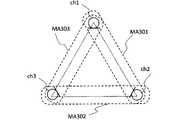
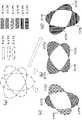
例えば、3個のマイクロホンを用いたエリア収音の構成を考えた場合、図4に示すように、マイクロホンの組み合わせによって最大3個のマイクアレイ(指向性の方向の異なる3個のマイクアレイ)を設定することができる。図4に示すように、3個のマイクロホンch1~ch3では、マイクロホンch1、ch2を対とするマイクアレイMA301、マイクロホンch2、ch3を対とするマイクアレイMA302、及びマイクロホンch3、ch1を対とするマイクアレイMA303を設定することができる。 For example, when considering an area sound pickup configuration using three microphones, as shown in Fig. 4, a maximum of three microphone arrays (three microphone arrays with different directivity directions) can be used depending on the combination of microphones. can be set. As shown in FIG. 4, three microphones ch1 to ch3 include a microphone array MA301 paired with microphones ch1 and ch2, a microphone array MA302 paired with microphones ch2 and ch3, and a microphone array MA302 paired with microphones ch3 and ch1. Array MA303 can be configured.
さらに、3個のマイクロホンch1~ch3の構成では、図5に示すように、3個のマイクアレイMA301、MA302、MA303の組み合わせ(3通りの組み合わせのパターン)に応じたエリア収音が可能となる。 Furthermore, in the configuration of three microphones ch1 to ch3, as shown in FIG. 5, it is possible to pick up sound in an area corresponding to the combination (three combination patterns) of the three microphone arrays MA301, MA302, and MA303. .
図5(a)では、マイクアレイMA301の指向性を一点鎖線で図示し、マイクアレイMA302の指向性を二点鎖線で図示している。また、図5(b)では、マイクアレイMA302の指向性を一点鎖線で図示し、マイクアレイMA303の指向性を二点鎖線で図示している。さらに、図5(c)では、マイクアレイMA301の指向性を一点鎖線で図示し、マイクアレイMA303の指向性を二点鎖線で図示している。さらにまた、図5(a)では、マイクアレイMA301、MA302の組み合わせ(パターン)に応じた収音エリアA301にハッチ(斜線)を付している。また、図5(b)では、マイクアレイMA302、MA303の組み合わせ(パターン)に応じた収音エリアA302にハッチ(斜線)を付している。さらに、図5(c)では、マイクアレイMA301、MA303の組み合わせ(パターン)に応じた収音エリアA303にハッチ(斜線)を付している。 In FIG. 5(a), the directivity of the microphone array MA301 is indicated by a one-dot chain line, and the directivity of the microphone array MA302 is indicated by a two-dot chain line. In FIG. 5(b), the directivity of the microphone array MA302 is indicated by a one-dot chain line, and the directivity of the microphone array MA303 is indicated by a two-dot chain line. Furthermore, in FIG. 5(c), the directivity of the microphone array MA301 is indicated by a one-dot chain line, and the directivity of the microphone array MA303 is indicated by a two-dot chain line. Furthermore, in FIG. 5A, the sound pickup area A301 corresponding to the combination (pattern) of the microphone arrays MA301 and MA302 is hatched (slanted lines). Also, in FIG. 5B, the sound pickup area A302 corresponding to the combination (pattern) of the microphone arrays MA302 and MA303 is hatched (slanted lines). Furthermore, in FIG. 5(c), the sound pickup area A303 corresponding to the combination (pattern) of the microphone arrays MA301 and MA303 is hatched (slanted lines).
図5に示すように、3個のマイクロホンch1~ch3の構成では、いずれのマイクアレイでも、マイクアレイ同士(マイクアレイを構成する2つのマイクロホンの位置を結ぶ線分同士)で角度を有することから、互いの指向性を交差させて、組み合わせ毎に異なるエリア収音(異なる領域のエリア収音)が実現可能である。 As shown in FIG. 5, in the configuration of three microphones ch1 to ch3, any microphone array has an angle between the microphone arrays (line segments connecting the positions of two microphones constituting the microphone array). , by crossing each other's directivities, different area sound pickup (area sound pickup in different regions) can be realized for each combination.
一方、マイクアレイを用いたエリア収音の収音エリアは、マイクアレイの前方(マイクアレイから遠い方)に拡がる性質がある。以下、その性質について図6を用いて説明する。 On the other hand, the sound pickup area of area sound pickup using a microphone array has the property of expanding in front of the microphone array (farther from the microphone array). The properties will be described below with reference to FIG.
図6は、2つのマイクアレイMA400、MA500の指向性を互いに直角を成すように交差させた場合におけるエリア収音の感度の分布(計算上の感度の分布)を示した図である。言い換えると、図6では、2つのマイクアレイMA400、MA500の指向性が交差する領域及びその周辺におけるエリア収音の感度を図示している。なお、図6では、マイクアレイMA400、MA500は、それぞれ2つのマイクロホンch1、ch2を備えている。また、図6では、エリア収音の感度を5段階(0~-5dB、-5~-10dB、-10~-15dB、-15~-20dB、-20~-25dB)に分けて、段階ごとに異なるパターン(模様)を付している。図6に示すように、マイクアレイMA400、MA500から遠い方(すなわち、右下方向)に向けて感度が高い領域が伸びている状態となることが分かる。 FIG. 6 is a diagram showing a sensitivity distribution (calculated sensitivity distribution) for area sound pickup when the directivities of the two microphone arrays MA400 and MA500 are crossed so as to form a right angle. In other words, FIG. 6 illustrates the area sound pick-up sensitivity in and around the area where the directivities of the two microphone arrays MA400 and MA500 intersect. In FIG. 6, the microphone arrays MA400 and MA500 each have two microphones ch1 and ch2. In addition, in FIG. 6, the sensitivity of area sound pickup is divided into five stages (0 to -5 dB, -5 to -10 dB, -10 to -15 dB, -15 to -20 dB, -20 to -25 dB), and each stage have different patterns. As shown in FIG. 6, it can be seen that the high-sensitivity region extends farther from the microphone arrays MA400 and MA500 (that is, toward the lower right).
したがって、図5(a)の組み合わせ(マイクアレイMA301、MA302の組み合わせ)、図5(b)の組み合わせ(マイクアレイMA302、MA303の組み合わせ)、図5(c)の組み合わせ(マイクアレイMA303、MA301の組み合わせ)によるエリア収音の収音エリア(エリア収音の感度の分布)は、それぞれマイクアレイの組み合わせ毎に異なり、重なる部分とそうでない部分(感度の分布が一致する部分と一致しない部分)が生じることになる。 Therefore, the combination of FIG. 5(a) (the combination of microphone arrays MA301 and MA302), the combination of FIG. 5(b) (the combination of microphone arrays MA302 and MA303), the combination of FIG. The area sound pickup area (sensitivity distribution of area sound pickup) differs for each combination of microphone arrays. will occur.
すなわち、図5に示すように、3個のマイクロホンch1~ch3の構成において、異なる2つないし3つのマイクアレイの組み合わせでエリア収音を行い、それぞれの収音結果を足し合わせれば、1つのマイクアレイの組合せで実現した収音エリアより広い範囲のエリア収音が可能になる。 That is, as shown in FIG. 5, in the configuration of three microphones ch1 to ch3, area sound pickup is performed by combining two or three different microphone arrays, and if the respective sound pickup results are added, one microphone It is possible to pick up sound in a wider range than the sound pickup area achieved by combining arrays.
そこで、この実施形態では、多角形(N角形;Nは3以上の整数)の角頂点の位置に配置されたマイクロホンで形成される複数のマイクアレイのうち、異なる複数のマイクアレイの組み合わせ(組み合わせのパターン)でエリア収音を行い、それぞれのエリア収音結果(エリア収音の出力)を加算又は加算平均した結果を、最終的な目的エリアの収音結果として取り扱う処理を行うものとする。これにより、この実施形態のエリア収音処理では、結果として話者の口元の位置(送話器から見た話者の口元の位置)の差異に対して、より頑健なエリア収音(より安定的なエリア収音)を行うことができる。 Therefore, in this embodiment, a combination (combination pattern), and the result of adding or averaging the area sound collection results (output of area sound collection) is treated as the final sound collection result of the target area. As a result, in the area sound pickup processing of this embodiment, area sound pickup is more robust (more stable) against the difference in the position of the speaker's mouth (the position of the speaker's mouth as seen from the transmitter). area sound pickup) can be performed.
(A-1)実施形態の構成
図1は、この実施形態に関連する各装置の構成について示したブロック図である。(A-1) Configuration of Embodiment FIG. 1 is a block diagram showing the configuration of each device related to this embodiment.
図1では、この実施形態に係る収音部120を備える通信装置100と、通信装置200とを図示している。また、図1では、通信装置100、200間は、通信路Pにより通信可能な構成となっている。 FIG. 1 illustrates a
通信装置100は、第1のユーザU1が発話した音声(音)を収音し、収音した音声の音声データを通信路Pを介して通信装置200に送信するとともに、通信装置200から受信した音声データに基づく音声(第2のユーザU2が発話した音声)を表音出力する装置である。また、通信装置200は、第2のユーザU2が発話した音声(音)を収音し、収音した音声の音声データを通信路Pを介して通信装置100に送信するとともに、通信装置100から受信した音声データに基づく音声(第1のユーザU1が発話した音声)を表音出力する装置である。 The
第1のユーザU1は、例えば、救急車や消防車等の緊急車両に登場する搭乗員等が該当し、第2のユーザU2としては、例えば、遠隔地(例えば、緊急車両を指揮する司令センタ)の司令担当者等が該当する。 The first user U1 is, for example, a crew member appearing in an emergency vehicle such as an ambulance or a fire engine. This applies to the commanding officer, etc.
通信路Pは、有線・無線に限定されず種々の接続手段や接続構成(ネットワーク構成)を適用することができる。 The communication path P is not limited to wired or wireless, and various connection means and connection configurations (network configurations) can be applied.
次に、通信装置100の構成概要について図1を用いて説明する。 Next, an overview of the configuration of the
通信装置100は、ハンドセット110、収音部120、通信部130、及び出力部140を有している。
ハンドセット110は、3個のマイクロホンMC1~MC3(3chマイクロホン)により構成されるマイクアレイ部111とスピーカ112とを備えている。 The
通信部130は、通信路Pを介して通信装置200と通信するための通信インタフェースである。 The
収音部120は、マイクアレイ部111で捕捉した音響信号に基づいて第1のユーザU1の発話した音声(音)を収音する。そして、通信部130は、収音部120が収音した音声の音声データを通信装置200側に送信する。 The
出力部140は、通信部130を介して通信装置200から音声データ(第2のユーザU2が発話した音声の音声データ)を取得し、当該音声データに基づく音響信号をスピーカ112に供給し、スピーカ112に当該音響信号を表音出力させる。 The
通信装置100のハードウェア的な構成については限定されないものであるが、この実施形態の例では、図1に示すように、通信装置100は、ハードウェア的にはハンドセット110を備える電話機の構成となっているものとする。なお、通信装置100は、必ずしもハンドセット110を備える必要はなく、スマートホンのように筐体(シャーシ)全体が、実質的にハンドセットとして機能する構成(例えば、スマートホンの筐体の一部に送話口が設定された構成)としてもよい。 Although the hardware configuration of the
次に、通信装置200の構成概要について図1を用いて説明する。 Next, an overview of the configuration of the
通信装置200は、スピーカ210、マイク220、通信部230、出力部240、及び収音部250を有している。通信装置200のハードウェア構成についても限定されないものであるが、例えば、種々の電話装置(例えば、スピーカホン等)を適用することができる。 The
通信部230は、通信路Pを介して通信装置200と通信するための通信インタフェースである。 The
収音部250は、マイク220で捕捉した音響信号に基づいて第2のユーザU2の発話した音声(音)を収音する。そして、通信部230は、収音部250が収音した音声の音声データを通信装置100側に送信する。 The
出力部240は、通信部230を介して通信装置100から音声データ(第1のユーザU1が発話した音声の音声データ)を取得し、当該音声データに基づく音響信号をスピーカ210に供給し、スピーカ210に当該音響信号を表音出力させる。 The
次に、収音部120の詳細構成について図1を用いて説明する。 Next, a detailed configuration of the
収音部120は、信号入力部121、周波数変換部122、指向性形成部123、目的エリア音抽出部124及びエリア音加算部125を有している。 The
収音部120は、例えば、プロセッサやメモリ等を備えるコンピュータにプログラム(実施形態に係る収音プログラムを含む)を実行させるようにしてもよいが、その場合であっても、機能的には、図1のように示すことができる。収音部120の各構成要素の処理の詳細については後述する。 For example, the
次に、送受話器としてのハンドセット110の構成について図2、図3を用いて説明する。 Next, the configuration of
図2は、ハンドセット110が第1のユーザU1の手U1aで把持されている状態について示した斜視図である。 FIG. 2 is a perspective view showing a state in which
図2に示すようにハンドセット110は、第1のユーザU1(手U1a)に把持させるための棒形状の把手部115と、把手部115の一端に設けられた送話口113(送話器)と、把手部115の他端に設けられた受話口114(受話器)とを有している。 As shown in FIG. 2, the
図3は、ハンドセット110の送話口113の部分を拡大して示した図である。 FIG. 3 is an enlarged view of the
図2、に示すように、受話口114にはスピーカ112が配置されている。また、図2、図3に示すように、円形の面を備える送話口113には、マイクアレイ部111(マイクロホンMC1~MC3)が配置されている。 As shown in FIG. 2, a
次に、マイクアレイ部111の構成について、図2、図3を用いて説明する。 Next, the configuration of the
この実施形態の例では、マイクアレイ部111は、3個のマイクロホンMC1~MC3を有する構成であるものとする。 In the example of this embodiment, the
図2に示すように、第1のユーザU1が通信装置100を手U1aで把持し、耳にスピーカSPを押し付けた場合に、第1のユーザU1の口元が位置する送話口113の周囲(第1のユーザU1の口元と最も近接する部分の周囲)に3個のマイクロホンMC1~MC3が配置されている。 As shown in FIG. 2, when the first user U1 holds the
図2、図3に示すハンドセット110では、上述の図4、図5に示す構成と同様に、マイクアレイ部111を構成する3個のマイクロホンMC1~MC3の各位置(各マイクロホンの中心位置)が、送話口113の周囲上で、正三角形の頂点となるように配置されている。図2、図3では、収音エリアの拡大を等方向とするため、マイクロホンMC1~MC3による三角形の各辺を同じ距離(マイクロホンMC1~MC3による三角形が正三角形)としているが、各辺の距離や各角の角度は全て同じでなくてもよい。 In the
なお、図3に示すように、以下では、マイクアレイ部111において、マイクロホンMC1、MC2を対とするマイクアレイをMA1、マイクロホンMC2、MC3を対とするマイクアレイをMA2、マイクロホンMC3、MC1を対とするマイクアレイをMA3と呼ぶものとする。 As shown in FIG. 3, in the
(A-2)実施形態の動作
次に、以上のような構成を有するこの実施形態の動作(実施形態に係る収音方法)を説明する。(A-2) Operation of Embodiment Next, the operation of this embodiment (sound pickup method according to the embodiment) having the configuration described above will be described.
通信装置100では、収音部120が、マイクアレイ部111のマイクロホンMC1~MC3から供給される音響信号を用いて、目的エリアの目的エリア音を収音する目的エリア音収音処理を行う。 In the
以下では、通信装置100を構成する収音部120内部の動作を中心に説明する。 The operation inside the
信号入力部121は、各マイクロホンMC1~MC3で収音した音響信号をアナログ信号からデジタル信号に変換し、周波数変換部122に供給する。その後、周波数変換部122では、例えば高速フーリエ変換を用いてマイク信号を時間領域から周波数領域へ変換する。指向性形成部123はBFにより指向性を形成する。 The
ここで、図7、図8を用いてBFによる指向性形成について説明する。 Here, directivity formation by BF will be described with reference to FIGS. 7 and 8. FIG.
BFとは、マイクアレイにおいて各マイクロホンに到達する信号の時間差を利用して収音の指向性を形成する技術である(非特許文献1参照)。BFは加算型と減算型の大きく2つの種類に分けられが、ここでは少ないマイクロホン数で指向性を形成できる減算型BFについて説明する。 BF is a technique for forming the directivity of sound pickup using the time difference between signals reaching each microphone in a microphone array (see Non-Patent Document 1). BFs are broadly classified into two types: addition type and subtraction type. Here, a subtraction type BF capable of forming directivity with a small number of microphones will be described.
図7は、マイクロホン数が2個(MC1、MC2)の場合の減算型BF600に係る構成を示すブロック図である。 FIG. 7 is a block diagram showing the configuration of the
図8は、2個のマイクロホンMC1、MC2を用いた減算型BF600により形成される指向特性を示す図である。 FIG. 8 is a diagram showing directivity characteristics formed by a
減算型BF600は、まず遅延器610により目的とする方向に存在する音(以下、「目的音」と呼ぶ)が各マイクロホンMC1、MC2に到来する信号の時間差を算出し、遅延を加えることにより目的音の位相を合わせる。時間差は(1)式により算出される。ここで、dはマイクロホンMC1、MC2間の距離、cは音速、τiは遅延量を示している。またθLは、マイクロホンMC1、M2の位置を結んだ直線に対する垂直方向から目的方向への角度を示している。The
ここで、死角をマイクロホンMC1とマイクロホンMC2の中心に対し、マイクロホンMC1の方向に向ける場合、遅延器610は、マイクロホンMC1の入力信号x1(t)に対し遅延処理を行う。その後、減算器620が、(2)式に従い減算処理を行う。減算器620では、この減算処理は周波数領域でも同様に行うことができ、その場合(2)式は(3)式のように変更される。
ここでθL=±π/2の場合、形成される指向性は図8(a)に示すように、カージオイド型の単一指向性となり、θL=0,πの場合は、図8(b)のような8の字型の双指向性となる。また、減算器620では、スペクトル減算法(Spectral Subtraction)の処理(以下、単に「SS」とも呼ぶ)を用いることで、双指向性の死角に強い指向性を形成することもできる。SSによる指向性は、(4)式に従い全周波数、もしくは指定した周波数帯域で形成される。(4)式では、マイクロホンMC1の入力信号X1を用いているが、マイクロホンMC2の入力信号X2でも同様の効果を得ることができる。ここで、nはフレーム番号、βはSSの強度を調節するための係数を示している。減算器620では、減算時に値がマイナスなった場合は、0または元の値を小さくした値に置き換えるフロアリング処理を行うようにしてもよい。この方式では、双指向性の特性によって目的方向以外に存在する音(以下、「非目的音」と呼ぶ)を抽出し、抽出した非目的音の振幅スペクトルを入力信号の振幅スペクトルから減算することで、目的音を強調することができる。
ところで、ある特定の目的エリア内に存在する目的エリア音だけを収音したい場合、減算型BFを用いるだけでは、そのエリアと同一方向の線上に存在する音源(以下、「非目的エリア音」と呼ぶ)も収音してしまう。 By the way, when it is desired to pick up only the target area sound existing in a certain target area, only using the subtractive BF will not detect the sound source existing on the line in the same direction as the area (hereinafter referred to as "non-target area sound"). call) will also be picked up.
そこで、指向性形成部123では、特許文献1で提案されているエリア収音処理(複数のマイクアレイを用い、それぞれ別々の方向から目的エリアへ指向性を向け、指向性を目的エリアで交差させることで目的エリア音を収音する処理)を行うものとして説明する。具体的には、指向性形成部123は、以下のような処理によりエリア収音処理を行うようにしてもよい。 Therefore, in the
指向性形成部123は、マイクアレイMA1~MA3のそれぞれについて、三角形(マイクロホンMC1~MC3により形成される三角形)の内側に向かってBFによって指向性を形成する。そして、指向性形成部123は、マイクアレイMA1、MA2、MA3の各BF出力Y1(n)、Y2(n)、Y3(n)を、目的エリア音抽出部124に供給する。The
目的エリア音抽出部124は、指向性形成部123で形成したマイクアレイMA1、MA2、MA3のBF出力Y1(n)、Y2(n)、Y3(n)を用いてエリア音を抽出する。上述の通り、各BF出力(Y1(n)、Y2(n)、Y3(n))は、3角形(マイクロホンMC1~MC3により形成される三角形)の各辺から中心(三角形の内側方向)に向かう指向性を成したものである。したがって、各BF出力は、そのいずれの2つの組み合せ(組み合わせのパターン)においても2つの指向性が3角形の中心付近で交差するため、目的エリア音抽出部124は、以下に記すエリア収音方法によって、互いの指向性が交差したエリアの音を抽出することが出来る。ここでは、代表として、マイクアレイMA1のBF出力Y1(n)と、マイクアレイMA2のBF出力Y2(n)を用いた場合について説明する。目的エリア音抽出部124は、Y1(n)、Y2(n)を(5)、もしくは(6)式に従いSSし、目的エリア方向に存在する非目的エリア音N1-1(n)、N1-2(n)を抽出する。ここでα1、α2は、目的エリアと各マイクアレイの距離の違いによって生じる信号レベルの差を補正する補正係数であり、所定の処理によって逐一計算されるべきものであり、その手法は特許文献1にも記載されているが、ここでは簡単のため、目的エリアと各マイクアレイまでの距離は同一(α1(n)=α2(n)=1)とし、(5)、(6)式を(7)、(8)式に代える。
その後、目的エリア音抽出部124は、(9)、(10)式に従い、各BF出力から非目的エリア音をSSして目的エリア音を抽出する。ここで、γ1(n)、γ2(n)はSS時の強度を変更するための係数である。
目的エリア音抽出部124において、強調音Z1-1(n)、Z1-2(n)のうちいずれを出力としても構わないが、ここではZ1-1(n)をマイクアレイMA1-マイクアレイMA2の組み合せ(組み合わせのパターン)によるエリア収音出力Z1(n)として用いることとする。In the target area
同様にして目的エリア音抽出部124は、マイクアレイMA2-マイクアレイMA3の組み合せによるエリア収音出力Z2(n)、及びマイクアレイMA3-マイクアレイMA1の組み合せによるエリア収音出力Z3(n)を抽出し、エリア音加算部125へ供給する。Similarly, the target area
図2に示すように、マイクロホンMC1~MC3は、いずれもハンドセット110の送話口113における数センチ径の狭い範囲に装着されている。したがって、各マイクアレイMA1、MA2、MA3は、非常に近接(密集)した配置であり、それぞれの収音エリアも送話口113前の狭い範囲に限られる。しかし、上述の図6に示すように、エリア収音による収音エリアは、2つのマイクアレイの遠方方向に拡がる特性があることが判っている。したがって、それぞれ異なる3方向に拡がった収音エリア(Z1(n)、Z2(n)、Z3(n)のそれぞれに対応する収音エリア)を重ね合わせれば、単独の収音エリア(Z1(n)、Z2(n)、Z3(n)のうちいずれか1つに対応する収音エリア)に比べ、より広い範囲のエリア収音が可能になる。As shown in FIG. 2, the microphones MC1 to MC3 are all mounted in a narrow range of several centimeters in diameter in the
そこで、エリア音加算部125では、3個のエリア収音の出力Z1(n)、Z2(n)、Z3(n)を加算又は加算平均して最終出力W(n)を生成して収音部120の収音結果として出力する。エリア音加算部125は、当該加算処理においてはエリア同士が重なる部分があることを考慮し、3個のエリア収音の出力の加算値(Z1(n)+Z2(n)、+Z3(n))を平均化、あるいは式(11)に示すようにゲイン調整の係数αを乗じてもよい。なお、エリア音加算部125は、3個のエリア収音の出力(Z1(n)、Z2(n)、Z3(n))のうち、2以上の出力だけを加算(又は加算平均)する処理を行うようにしてもよい。例えば、エリア音加算部125は、3個のエリア収音の出力のうち、2つの出力だけを加算(又は加算平均)する処理を行うようにしてもよい。
以上のように、収音部120は、拡大されたエリアから収音された目的音声として最終出力W(n)を出力する。このとき、収音部120は、W(n)を周波数-時間変換した音声データとして出力するようにしてもよい。 As described above, the
そして、通信部130は、最終出力W(n)に基づく音声データを、通信路Pを介して通信装置200に送信する。 The
そして、通信装置200の通信部230は、通信装置100から受信した音声データ(W(n)に基づく音声データ)を出力部140に供給する。出力部140は、受信した音声データに基づく音響信号をスピーカ210に供給して表音出力(第2のユーザU2に向けて表音出力)させる。 Then, the
(A-3)実施形態の効果
この実施形態によれば、以下のような効果を奏することができる。(A-3) Effects of Embodiment According to this embodiment, the following effects can be obtained.
この実施形態の収音部120では、別々の方向からエリア収音を行い、それらを足し合わせることで、従来の1組(2つ)のマイクアレイを用いたエリア収音よりも広く、等方向性をもった収音エリア(拡大した収音エリア)を形成することができる。これにより、収音部120では、ハンドセット110の送話口113に付けられたマイクロホンMC1~MC3を用いたエリア収音を行う際に、話者(第1のユーザU1)の口元と送話口113との相対的な位置がずれた場合でも安定した音声収音が可能となる。 The
(B)第2の実施形態
以下、本発明による収音装置、プログラム及び方法の第2の実施形態を、図面を参照しながら詳述する。この実施形態では、本発明の収音装置、プログラム及び方法を収音部に適用した例について説明する。(B) Second Embodiment Hereinafter, a second embodiment of the sound collecting device, program and method according to the present invention will be described in detail with reference to the drawings. In this embodiment, an example in which the sound collecting device, program, and method of the present invention are applied to a sound collecting unit will be described.
(B-1)第2の実施形態の構成
図9は、第2の実施形態に関連する各装置の構成について示したブロック図である。図9では、上述の図1と同一部分又は対応部分には、同一符号又は対応符号を付している。(B-1) Configuration of Second Embodiment FIG. 9 is a block diagram showing the configuration of each device related to the second embodiment. In FIG. 9, the same reference numerals or corresponding reference numerals are assigned to the same or corresponding portions as those in FIG.
第2の実施形態では、通信装置100が通信装置100Aに置き換わっている。また、第2の実施形態の通信装置100Aでは、マイクアレイ部111と収音部120が、マイクアレイ部111Aと収音部120Aに置き換わっている。 In the second embodiment, the
次に、第2の実施形態における収音部120Aの内部構成について説明する。 Next, the internal configuration of the
上述の通り、第1の実施形態の収音部120では、別々の方向からエリア収音を行い、それらを重ね合わせる(足し合わせる)ことで、従来の1組(2つ)のマイクアレイを用いたエリア収音よりも広く、等方向性をもった収音エリア(拡大した収音エリア)を形成している。 As described above, the
しかしながら、第1の実施形態のようなエリア収音処理では、重ね合わせる各収音エリアが独立している場合であれば、単なる重ね合わせでも問題は生じないが、収音エリア同士に収音エリアの重複がある場合、複合(統合)された収音エリア内で均一な収音特性を得ることが困難になる。重複部分を有する複数の収音エリアの収音結果を足し合わせると、重複した部分のゲインは重複しない部分のそれに対して、成分が足し合わされることで、より強調されたものとなる。拡張された収音エリアに関して、収音エリア内の収音特性は結果として不均一なものとなり、収音エリアに存在する目的音源が持つ本来の特性とは異なる特性になってしまう場合がある。とりわけ音源位置が重複部分と重複しない部分に跨る場合には特性が歪曲される可能性が高い。 However, in the area sound collection processing of the first embodiment, if the sound collection areas to be superimposed are independent, no problem will occur even if the sound collection areas are simply superimposed. , it becomes difficult to obtain uniform sound pickup characteristics within the combined (integrated) sound pickup area. When the sound pickup results of a plurality of sound pickup areas having overlapping portions are added, the gain of the overlapping portions is emphasized by adding the gain components to those of the non-overlapping portions. As for the expanded sound collection area, the sound collection characteristics within the sound collection area become uneven as a result, and may differ from the original characteristics of the target sound source existing in the sound collection area. In particular, when the sound source position straddles an overlapping portion and a non-overlapping portion, there is a high possibility that the characteristics will be distorted.
そこで、第2の実施形態の収音部120Aでは、複数の収音エリアからエリア収音を行なう場合、たとえ収音エリア同士の重なりがあっても均一な収音特性を実現し、歪の少ない安定した収音方法を提供することを目的とする。 Therefore, in the
具体的には、第2の実施形態の収音部120Aでは、重複部分を有する複数の収音エリアのエリア収音成分(エリア収音出力)に対し、それぞれの収音エリアのエリア収音成分を用いて、重複部分のエリア収音成分と、重複しない部分のエリア収音成分を個別に算出し、当該個別に算出されたエリア収音成分を統合して複数の収音エリアの全範囲をカバーするエリア収音成分を得て出力とする。これにより、第2の実施形態の収音部120Aでは、複数の収音エリアで重複部分が存在しても、第1の実施形態のように重複部分のエリア収音成分をダブルカウントすることなく、複数の収音エリアの全範囲にわたって収音特性の均一性を保つことができる。 Specifically, in the
次に、収音部120Aの内部構成について図9を用いて説明する。 Next, the internal configuration of the
収音部120Aでは、目的エリア音抽出部124が目的エリア音抽出部124Aに置き換わり、エリア音加算部125が除外されている点で第1の実施形態と異なっている。また、収音部120Aでは、独立エリア成分算出部126と部分エリア統合部127が追加されている点で第1の実施形態と異なっている。 The
次に、第2の実施形態のマイクアレイ部111Aの構成について説明する。 Next, the configuration of the microphone array section 111A of the second embodiment will be described.
図9に示すように、第2の実施形態において、マイクアレイ部111Aは、6つのマイクロホンMC1~MC6を有している。 As shown in FIG. 9, in the second embodiment, the microphone array section 111A has six microphones MC1 to MC6.
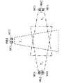
図10は、マイクアレイ部111Aにおける6つのマイクロホンMC1~MC6の配置及びマイクアレイの構成例について示した図である。 FIG. 10 is a diagram showing an arrangement of the six microphones MC1 to MC6 in the microphone array section 111A and a configuration example of the microphone array.
図10に示すように、マイクアレイ部111Aを構成する6つのマイクロホンMC1~MC6は、2つずつのマイクロホンを対として3つのマイクアレイMA1(マイクロホンMC1、MC2を対とするマイクアレイ)、MA2(マイクロホンMC3、MC4を対とするマイクアレイ)、MA3(マイクロホンMC5、MC6を対とするマイクアレイ)を構成している。第2の実施形態では、第2の実施形態に係る収音方法の原理を解り易く説明するため、重なりを持つ2つのエリアのエリア収音を行なう構成を用いている。 As shown in FIG. 10, the six microphones MC1 to MC6 that constitute the microphone array section 111A are divided into three microphone arrays MA1 (microphone array paired with microphones MC1 and MC2) and MA2 (microphone arrays paired with two microphones each). A microphone array paired with microphones MC3 and MC4) and MA3 (a microphone array paired with microphones MC5 and MC6). In the second embodiment, in order to explain the principle of the sound pickup method according to the second embodiment in an easy-to-understand manner, a configuration for performing area sound pickup in two overlapping areas is used.
(B-2)第2の実施形態の動作
次に、以上のような構成を有する第2の実施形態の動作(実施形態に係る収音方法)を説明する。(B-2) Operation of Second Embodiment Next, the operation of the second embodiment having the above configuration (sound pickup method according to the embodiment) will be described.
信号入力部121は、6つのマイクロホンで収音した音響信号をアナログ信号からデジタル信号に変換し(x1~x6)、周波数変換部122に供給する。The
周波数変換部122では、例えば高速フーリエ変換を用いてマイクロホン信号を時間領域から周波数領域へ変換する(X1~X6)。The
指向性形成部123は、周波数変換部122によって時間-周波数変換された各マイクロホンの入力信号を用いてBFにより指向性を形成する。第2の実施形態では、マイクアレイMA1によるBF出力をY1、マイクアレイMA2によるBF出力をY2、マイクアレイMA3によるBF出力をY3とする。BF出力Y1、Y2、Y3の指向性は図10に示す通りである。第2の実施形態では図10に示す通り、マイクアレイMA1~MA3が三角形の各頂点の位置に配置されており、BF出力Y1、Y2、Y3の指向性(マイクアレイMA1~MA3の指向性)はそれぞれ三角形の内側を向けられている。
目的エリア音抽出部124Aでは、指向性形成部123で生成されたBF出力を用いてエリア収音処理を行なう。エリア収音は、異なる方向からBFの指向性を向け、指向性が交差したエリアの成分(エリア音)を分離・抽出するものである。BF出力Y1、BF出力Y2の組み合わせ、およびBF出力Y1、BF出力Y3の組み合わせのそれぞれからエリア収音が実現できる。The target area
図11は、目的エリア音抽出部124Aがエリア収音をおこなう収音エリアの分布について示した説明図である。 FIG. 11 is an explanatory diagram showing the distribution of sound pickup areas where the target area
上述の図6で示したように、エリア収音ではマイクアレイから遠い方向に収音エリアが広がる特性を持つ。そのため、マイクアレイMA1-MA2によるエリア収音領域(第2の実施形態では、「エリア1」又は「収音エリア1」と呼ぶ)と、マイクアレイMA2-MA3によるエリア収音領域(第2の実施形態では、「エリア2」又は「収音エリア2」と呼ぶ)は、図11のようなイメージになる。第2の実施形態では、収音エリア1のエリア収音成分(エリア収音出力)をZ1、エリア2のエリア収音成分(エリア収音出力)をZ2とする。As shown in FIG. 6, area sound pickup has the characteristic that the sound pickup area spreads in the direction far from the microphone array. Therefore, an area sound pickup area by the microphone arrays MA1-MA2 (referred to as "
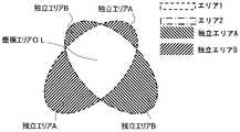
それぞれの収音エリアは、図12のように2つの収音エリアが重複する部分と、重複しない独立した部分に分けられる。 Each sound pickup area is divided into a portion where two sound pickup areas overlap and an independent portion where two sound pickup areas do not overlap, as shown in FIG.
図12では、エリア1、2で重複する領域を重複エリアOLとしている。また、図12では、エリア1内で、重複エリアOLを除く独立した領域(他の収音エリアと重複していない領域)を独立エリアAとしている。さらに、図12では、エリア2内で、重複エリアOLを除く独立した領域を独立エリアBとしている。なお、1つの収音エリアから発生する独立エリア(独立部分)は、図12に示すように複数の領域に分割される場合が有りえるが、本明細書では1つの収音エリアから発生した独立エリアについてはまとめて1つの符号で示すものとする。例えば、図12では、に独立エリアAは重複エリアOLにより2つの領域に分割(分断)されているが、ここでは、この2つの領域をまとめて独立エリアAと呼ぶことになる。 In FIG. 12, a region where
以上により、エリア1は重複エリアOLと独立エリアA(エリア1から重複エリアOLを除いた領域)とから成り、エリア2は重複エリアOLと独立エリアB(エリア2から重複エリアOLを除いた領域)とから成る。エリア1のエリア収音出力Z1と、エリア2のエリア収音出力Z2を重ね合わせる(足し合わせる)と、広い範囲のエリアから収音できるが、重複エリアOLの成分が二重に加わることになり収音エリア全体として均一な収音特性は得られない。したがって、重複エリアOLと独立エリアA、Bの音源を個別に分離・抽出することができれば、それぞれのエリアを重複することなく統合することでエリア1、2の全範囲に亘って均一な収音特性が得られることになる。As described above,
独立エリア成分算出部126では、重複エリアOLを有する2つのエリア収音成分(ここでは、エリア1、2のエリア収音成分)から、独立エリアのエリア収音成分(ここでは、独立エリアA、Bのエリア収音成分)を分離する。 In the independent area
図13は、図12に示す各エリアの組成イメージ(成分ごとのパワー)を棒グラフの形式で示した説明図である。 FIG. 13 is an explanatory diagram showing a composition image (power for each component) of each area shown in FIG. 12 in the form of a bar graph.
図13(a)は、エリア1のエリア収音成分Z1の組成イメージ示し、図13(b)は、エリア2のエリア収音成分Z2の組成イメージを示している。また、図13(c)は、図13(a)に示すエリア収音成分Z1の組成イメージについて、重複エリアOLの成分にハッチ(斜線パターン)を付して示したものである。さらに、図13(d)は、図13(b)に示すエリア収音出力Z2の組成イメージについて、重複エリアOLの成分にハッチ(斜線パターン)を付して示したものである。13(a) shows a composition image of area picked-up sound component Z1 of
エリア1とエリア2の重複エリアOLは、文字通り重複して共通であるから、Z1とZ2の中にそれぞれ同一の成分として含まれている。そこで、目的エリア音抽出部124Aでは、エリア収音と同じ原理に基づき、スペクトル減算法(SS)を用いることで、それぞれの成分を分離する。Since the overlapping area OL of area1 and area2 is literally overlapping and common, it is included in Z1 and Z2 as the same component. Therefore, the target area
独立エリア成分算出部126は、エリア収音出力Z1からエリア収音出力Z2をSSする。独立エリア成分算出部126は、SSに際して負になる成分は0にクリッピングする。そうすることで、目的エリア音抽出部124Aでは、エリア収音出力Z1から重複エリアOLのエリア収音成分が除かれ、独立エリアAのエリア収音成分(第1の実施形態では「VA」と呼ぶ)が分離される。同様に、独立エリア成分算出部126は、エリア収音出力Z2からエリア収音出力Z1をSSすることで、独立エリアBのエリア収音成分(第1の実施形態では、「VB」と呼ぶ)を分離することができる。The independent
図14は、独立エリア成分算出部126による処理の手順を示した説明図である。 FIG. 14 is an explanatory diagram showing the procedure of processing by the independent area
図14(a)~図14(c)は、独立エリア成分算出部126が、エリア1のエリア収音出力Z1から、エリア2のエリア収音出力Z2をSSして独立エリアAのエリア収音成分VAを抽出する処理(以下の(21)式に相当する処理)について示している。図14(a)~図14(c)は、それぞれエリア1のエリア収音成分Z1、エリア2のエリア収音成分Z2、独立エリアAのエリア収音成分VAの組成イメージを表している。14(a) to 14(c), the independent area
また、図14(d)~図14(f)は、独立エリア成分算出部126が、エリア2のエリア収音成分Z2から、エリア1のエリア収音成分Z1をSSして独立エリアBのエリア収音成分VBを抽出する処理(以下の(22)式に相当する処理)について示している。図14(d)~図14(f)は、それぞれ、エリア2のエリア収音成分Z2、エリア1のエリア収音成分Z1、独立エリアBのエリア収音成分VBの組成イメージを表している。14(d) to 14(f), the independent area
なお、図14に示す各組成イメージでは、重複エリアOLのエリア収音成分と、独立エリアAのエリア収音成分VAと、独立エリアBのエリア収音成分VBとに、それぞれ異なるパターンを付して図示している。Note that in each composition image shown in FIG. 14, different patterns are used for the area picked-up sound component of the overlapping area OL, the area picked-up sound component VA of the independent area A, and the area picked-up sound component VB of the independent area B. It is attached and illustrated.
以上のように、独立エリア成分算出部126では、重複エリアOLを含む2つのエリア1、2に対し、片方の収音エリアだけにしか含まれない独立エリアのエリア収音成分を個別に分離・抽出する。 As described above, the independent area
部分エリア統合部127は、分離された各独立エリアのエリア収音成分(VA、もしくはVB)と、当該独立エリア成分を含まないエリア音成分(Z2、もしくはZ1)とを統合して、最終的な最終出力Wを算出して出力する。部分エリア統合部127は、例えば、以下の(23)式又は(24)式を用いて最終出力Wを算出する。
以上のように、収音部120Aは、拡大されたエリアから収音された目的音声として最終出力W(n)を出力する。 As described above, the
そして、通信部130は、最終出力W(n)に基づく音声データを、通信路Pを介して通信装置200に送信する。 The
そして、通信装置200の通信部230は、通信装置100から受信した音声データ(W(n)に基づく音声データ)を出力部140に供給する。出力部140は、受信した音声データに基づく音響信号をスピーカ210に供給して表音出力(第2のユーザU2に向けて表音出力)させる。 Then, the
(B-3)第2の実施形態の効果
第2の実施形態によれば、以下のような効果を奏することができる。(B-3) Effects of Second Embodiment According to the second embodiment, the following effects can be obtained.
第2の実施形態の収音部120Aでは、別々の方向からエリア収音を行い、従来の1組のマイクアレイを用いたエリア収音よりも広く、等方向性をもった収音エリアを形成することができる。 The
また、第2の実施形態の最終出力Wでは、同一周波数成分に対して1つのエリア音出力のみが選択されて出力されるため、エリア拡大においても収音特性の均一性が保たれる。これにより、例えば、第2の実施形態の収音部120Aをハンドセットに適用する際であっても、利用者の口元が送話口からずれても安定した収音が可能になる。 Further, in the final output W of the second embodiment, only one area sound output is selected and output for the same frequency component, so even when the area is expanded, the uniformity of the sound pickup characteristics is maintained. As a result, for example, even when the
(C)第3の実施形態
以下、本発明による収音装置、プログラム及び方法の第3の実施形態を、図面を参照しながら詳述する。この実施形態では、本発明の収音装置、プログラム及び方法を収音部に適用した例について説明する。(C) Third Embodiment Hereinafter, a third embodiment of the sound collecting device, program and method according to the present invention will be described in detail with reference to the drawings. In this embodiment, an example in which the sound collecting device, program, and method of the present invention are applied to a sound collecting unit will be described.
(C-1)第3の実施形態の構成
図15は、第3の実施形態に関連する各装置の構成について示したブロック図である。(C-1) Configuration of Third Embodiment FIG. 15 is a block diagram showing the configuration of each device related to the third embodiment.
図15では、上述の図1又は図9と同一部分又は対応部分には、同一符号又は対応符号を付している。以下では、第3の実施形態について、第1、第2の実施形態との差異を中心に説明する。 In FIG. 15, the same reference numerals or corresponding reference numerals are given to the same or corresponding portions as those in FIG. 1 or FIG. 9 described above. The third embodiment will be described below, focusing on differences from the first and second embodiments.
第3の実施形態では、通信装置100Aが通信装置100Bに置き換わっている点で第2の実施形態と異なっている。また、第3の実施形態の通信装置100Bでは、マイクアレイ部111Aがマイクアレイ部111(第1の実施形態と同様の構成)に置き換わっている点で第2の実施形態と異なっている。さらに、第3の実施形態の通信装置100Bでは、収音部120Aが収音部120Bに置き換わっている点で第2の実施形態と異なっている。 The third embodiment differs from the second embodiment in that the
次に、第3の実施形態における収音部120Bの内部構成について説明する。 Next, the internal configuration of the
第3の実施形態の収音部120Bでは、目的エリア音抽出部124Aと独立エリア成分算出部126と部分エリア統合部127とが、目的エリア音抽出部124(第1の実施形態と同様の構成)と独立エリア成分算出部126Bと部分エリア統合部127Bとに置き換わっている点で第2の実施形態と異なっている。 In the
上述の通り、第3の実施形態におけるマイクアレイ部111は、第1の実施形態と同様に、3つのマイクロホンMC1~MC3により構成されている。第3の実施形態において、3つのマイクロホンMC1~MC3は、上述の図2、図3と同様に、ハンドセット110の送話口113表面に正三角形となるように配置されている。なお、この実施形態では、収音エリアの拡大を等方向にするため、マイクロホンMC1~MC3を正三角形に配置したが、必ずしも正三角形に限定されるものではない。 As described above, the
第3の実施形態では、第1の実施形態と同様に、3個のマイクロホンMC1~MC3から3個のマイクアレイMA1~MA3を構成する(上述の図4参照)。詳細については後述するが、第3の実施形態の通信装置100B(収音部120B)では、マイクアレイMA1~MA3の組み合わせによって3つの収音エリアについてエリア収音を行なう。 In the third embodiment, as in the first embodiment, three microphone arrays MA1 to MA3 are configured from three microphones MC1 to MC3 (see FIG. 4 described above). Although the details will be described later, in the
(C-2)第3の実施形態の動作
次に、以上のような構成を有する第3の実施形態の動作(実施形態に係る収音方法)を説明する。(C-2) Operation of the Third Embodiment Next, the operation of the third embodiment (sound pickup method according to the embodiment) having the configuration as described above will be described.
信号入力部121は、3つのマイクロホンMC1~MC3で収音した音響信号をアナログ信号からデジタル信号に変換し(x1~x3)、周波数変換部122に供給する。The
周波数変換部122では、例えば、高速フーリエ変換を用いてマイクロホン信号を時間領域から周波数領域へ変換する(X1~X3)。The
指向性形成部123は、周波数変換部122によって時間-周波数変換された各マイクロホンの入力信号を用いてBFにより指向性を形成する。第3の実施形態では、マイクアレイMA1によるBF出力をY1、マイクアレイMA2によるBF出力をY2、マイクアレイMA3によるBF出力をY3とする。
目的エリア音抽出部124では、指向性形成部123で形成したBF出力Y1、Y2、Y3、を用い、Y1-Y2、Y2-Y3、Y3-Y1の組合せで、それぞれエリア収音処理を行なう。The target area
第3の実施形態では、Y1-Y2の組み合せによるエリア(収音エリア)を「1」、Y2-Y3の組み合せによるエリア(収音エリア)を2、Y3-Y1の組み合せによるエリア(収音エリア)を「3」と呼ぶものとする。In the third embodiment, the area (sound pickup area) of the combination of Y1 -Y2 is "1", the area (sound pickup area) of the combination of Y2 -Y3 is 2, and the combination of Y3 -Y1 The area (sound pickup area) due to is called "3".
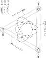
上述の図6で示したように、エリア収音ではマイクアレイから遠い方向に収音エリアが広がる特性を持つ。そのため、BF出力Y1-Y2(マイクアレイMA1-MA2)によるエリア1、BF出力Y2-Y3(マイクアレイMA2-MA3)によるエリア2、BF出力Y3-Y1(マイクアレイMA3-MA1)による収音エリアの分布は、図16のようなイメージになる。なお、第3の実施形態では、エリア1、2、3のそれぞれのエリア収音成分(エリア収音出力)をZ1、Z2、Z3とする。As shown in FIG. 6, area sound pickup has the characteristic that the sound pickup area spreads in the direction far from the microphone array. Therefore,
第2の実施形態では2つの収音エリアの重複を考えたが、第3の実施形態では収音エリアが3つになる。したがって、第3の実施形態では、3つの収音エリアが重複する部分、2つのエリアが重複する部分、重複なく独立した部分というように、第2の実施形態と比較して重複のパターンがより複雑になる。 In the second embodiment, two sound pickup areas overlap, but in the third embodiment, there are three sound pickup areas. Therefore, in the third embodiment, there are more overlap patterns than in the second embodiment, such as a portion in which three sound pickup areas overlap, a portion in which two areas overlap, and a portion that is independent without overlap. it gets complicated.
部分エリア統合部127Bではエリア収音出力Z1、Z2、Z3を用い、3つの収音エリアが重複する部分、2つの収音エリアが重複する部分、重複なく独立した部分のエリア収音成分をそれぞれ算出する。部分エリア統合部127Bでは、各部分のエリア収音成分を算出する際に、2つの収音エリアの各組み合わせ(エリア1、2の組み合わせ、エリア2、3の組み合わせ、エリア3、1の組み合わせ)のパターン(以下、「組み合わせパターン」と呼ぶ)に分解することで、第2の実施形態と同じ手法が利用可能となる。具体的には、部分エリア統合部127Bにおいて、重複エリアを有する2つの収音エリアのエリア収音成分を、重複エリアの部分と、独立エリアの部分に分離する処理は第1の実施形態と同様である。The area sound pickup outputs Z1 , Z2 , and Z3 are used in the partial
以下では、エリア1、2の組み合わせパターンを「第1の組み合わせパターン」と呼び、エリア2、3の組み合わせパターンを「第2の組み合わせパターン」と呼び、エリア3、1の組み合わせパターンを「第3の組み合わせパターン」と呼ぶものとする。 Hereinafter, the combination pattern of
図17は、3つのエリア1~3について2つの収音エリアの組み合わせパターン(第1~第3の組み合わせパターン)の分解イメージについて示した説明図(イメージ図)である。 FIG. 17 is an explanatory diagram (image diagram) showing an exploded image of combination patterns (first to third combination patterns) of two sound pickup areas for three
図17(a)は、3つのエリア1~3を重ねて示した図となっている。図17(b)~図17(d)は、それぞれ第1~第3の組み合わせパターンに分解したイメージについて示した説明図である。 FIG. 17(a) is a diagram showing three
まず、図17(b)~図17(d)に示す3つの組み合わせパターンから、図17(b)に示す第1の組み合わせパターン(エリア1、2の組み合わせパターン)を代表例として説明する。 First, of the three combination patterns shown in FIGS. 17B to 17D, the first combination pattern (combination pattern of
独立エリア成分算出部126Bは、エリア収音出力Z1からエリア収音出力Z2をSSすることで、エリア1のエリア2に対して独立した部分(この実施形態では、「エリアA」と呼ぶものとする;図17(b)参照)のエリア収音成分(第3の実施形態では「VA」と呼ぶ)を得る。また、独立エリア成分算出部126Bは、エリア収音出力Z2からエリア収音出力Z1をSSすることで、エリア2のエリア1に対して独立した部分(この実施形態では、「エリアB」と呼ぶものとする;図17(b)参照)のエリア収音成分(第3の実施形態では「VB」と呼ぶ)を得ることができる。独立エリア成分算出部126Bでは、第2の実施形態と同様に、上記の(21)式、(22)式の計算式により、エリア収音成分VA、VBを得ることができる。The independent area
独立エリア成分算出部126Bでは、第2の組み合わせパターン(エリア2、3の組み合わせパターン)についても同様に、エリア2のエリア3に対して独立した部分(この実施形態では、「エリアC」と呼ぶものとする;図17(c)参照)のエリア収音成分(第3の実施形態では「VC」と呼ぶ)と、エリア3のエリア2に対して独立した部分(第3の実施形態では、「エリアD」と呼ぶものとする;図17(c)参照)のエリア収音成分(第3の実施形態では「VD」と呼ぶ)を得ることができる。また、独立エリア成分算出部126Bでは、第3の組み合わせパターン(エリア3、1の組み合わせパターン)についても同様に、エリア3のエリア1に対して独立した部分(この実施形態では、「エリアE」と呼ぶものとする;図17(d)参照)のエリア収音成分(第3の実施形態では「VE」と呼ぶ)と、エリア1のエリア3に対して独立した部分(この実施形態では、「エリアF」と呼ぶものとする;図17(d)参照)のエリア収音成分(第3の実施形態では「VF」と呼ぶ)を得ることができる。In the independent area
独立エリア成分算出部126Bでは、下記の(31)式~(34)式の計算式により、エリア収音成分VC、VD、VE、VFを得ることができる。
以上のように、独立エリア成分算出部126Bは、エリア1、エリア2、エリア3のうち、任意の2つのエリアの組み合せ(いずれかの組み合わせパターン)で生じる独立部分(エリアA~F)のエリア収音成分(VA~VF)について算出することができる。これにより、独立エリア成分算出部126Bは、その独立部分のエリア収音成分(VA~VF)を元に、エリア1~3を同時に重ねた場合の独立エリアのエリア収音成分を算出することができる。As described above, the independent area
ここでは、まず、独立エリア成分算出部126Bが、エリアA、Dで生じる独立部分のエリア収音成分を求める処理について説明する。 Here, first, the process of obtaining the area picked-up sound components of the independent portions generated in the areas A and D by the independent
図18は、エリアA、Dで生じる独立部分のイメージについて示した説明図である。 18A and 18B are explanatory diagrams showing images of independent portions generated in areas A and D. FIG.
独立エリア成分算出部126Bは、上記の計算でエリアAのエリア収音成分VAと、エリアDのエリア収音成分成分VDを得ることができる。The independent
そして、独立エリア成分算出部126Bは、これまでと同様の計算方法により、エリア収音成分VAからエリア収音成分成分VDをSSすることで、エリアAのエリアDに対して独立した部分(すなわちエリアA内の独立部分;この実施形態では、「エリアAd」と呼ぶものとする)のエリア収音成分(第3の実施形態では「VAd」と呼ぶ)を得ることができる。独立エリア成分算出部126Bでは、下記の(35)式により、エリア収音成分VAdを得ることができる。Then, the independent area
これにより、独立エリア成分算出部126Bでは、以下の(36)式に示すように、エリア収音成分VAdとエリア収音成分VDを加算することで、エリアAとエリアDの範囲全体(以下、「エリアA∨D」と表す)のエリア収音成分(以下、「VA∨D」と表す」を得ることができる。As a result, the independent area
図19は、エリア1~3におけるエリアA∨Dのイメージについて示した説明図である。 FIG. 19 is an explanatory diagram showing an image of area A∨D in areas 1-3.
なお、エリアA∨Dのエリア収音成分VA∨Dは、以下の(37)式、(38)式に示すように、エリアDのエリアAに対して独立した部分(すなわちエリアD内の独立部分;この実施形態では、「エリアDa」と呼ぶものとする)のエリア収音成分(第3の実施形態では「VDa」と呼ぶ)と、エリアAのエリア収音成分VAを加算して得るようにしてもよい。
図19に示すように、エリアA∨D(エリアAとエリアDの範囲全体部分)は、エリア2からはみ出した部分(エリア1~3の範囲全体においてエリア2からはみ出した部分全体)である。したがって、後述するように、部分エリア統合部127Bは、エリア収音成分VA∨Dを用いて、エリア1~3全体の範囲のエリア収音成分(最終出力W)を算出することができる。As shown in FIG. 19, area A∨D (the entire range of area A and area D) is a portion protruding from area 2 (the entire portion protruding from
以上のように、独立エリア成分算出部126Bは、エリアA∨D(エリアAとエリアDの範囲全体)のエリア収音成分VA∨Dを得ることができる。As described above, the independent
以上の図18、図19の例では、エリアA又はエリアDで発生する独立部分のエリア収音成分を用いて、エリアA∨D(エリアA、Dの範囲全体;エリア3からはみ出る部分)のエリア収音成分VA∨Dを得る例について示したが、同様に、エリアB又はエリアEで発生する独立エリアのエリア収音成分を用いて、エリアB、Eの範囲全体(エリア1からはみ出る部分;以下、「エリアB∨E」と呼ぶ)のエリア収音成分(以下、「VB∨E」と呼ぶ)や、エリアC又はエリアFで発生する独立エリアのエリア収音成分を用いて、エリアC、Fの範囲全体(エリア3からはみ出る部分;以下、「エリアC∨F」と呼ぶ)のエリア収音成分(以下、「VC∨F」と呼ぶ)を求めるようにしてもよい。In the examples of FIGS. 18 and 19 above, the area A∨D (the entire range of areas A and D; the portion protruding from area 3) is An example of obtaining the area picked-up sound component VA∨D was shown, but similarly, using the area picked-up sound component of the independent area generated in the area B or the area E, the entire range of the areas B and E (protruding from the
図20は、エリアB、Eで発生する独立部分のイメージについて示した説明図である。 FIG. 20 is an explanatory diagram showing an image of independent portions generated in areas B and E. FIG.
独立エリア成分算出部126Bは、上述のエリアA、Dの場合と同様の計算方法により、エリアBのエリアEに対して独立した部分(すなわちエリアB内の独立エリア;この実施形態では、「エリアBe」と呼ぶものとする)のエリア収音成分(第3の実施形態では「VBe」と呼ぶ)や、エリアEのエリアBに対して独立した部分(すなわちエリアE内の独立エリア;この実施形態では、「エリアEb」と呼ぶものとする)のエリア収音成分(第3の実施形態では「VEb」と呼ぶ)を得ることができる(具体的な計算式は下記の(39)式、(41)式参照)。そして、独立エリア成分算出部126Bは、エリア収音成分VBe又はエリア収音成分VEbを用いて、エリアB∨E(エリア1からはみ出した部分)のエリア収音成分VB∨Eを得ることができる(具体的な計算式は下記の(40)式、(42)式参照)。The independent area
図21は、エリアC、Fで発生する独立部分のイメージについて示した説明図である。 FIG. 21 is an explanatory diagram showing an image of independent portions generated in areas C and F. FIG.
独立エリア成分算出部126Bは、上述のエリアA、Dの場合と同様の計算方法により、エリアCのエリアFに対して独立した部分(すなわちエリアC内の独立エリア;この実施形態では、「エリアCf」と呼ぶものとする)のエリア収音成分(第3の実施形態では「VCf」と呼ぶ)や、エリアFのエリアCに対して独立した部分(すなわちエリアF内の独立エリア;この実施形態では、「エリアFc」と呼ぶものとする)のエリア収音成分(第3の実施形態では「VFc」と呼ぶ)を得ることができる(具体的な計算式は下記の(43)式、(45)式参照)。そして、独立エリア成分算出部126Bは、エリア収音成分VCf又はエリア収音成分VFcを用いて、エリアC∨F(エリア3からはみ出した部分)のエリア収音成分VC∨Fを得ることができる(具体的な計算式は下記の(44)式、(46)式参照)。
以上のように、独立エリア成分算出部126Bでは、エリア1~3の重なりから独立したエリアのエリア収音成分算出を経て、エリア1~3のいずれかからはみ出した部分のエリア収音成分(VA∨D、VB∨E、VC∨Fのいずれか)を算出する。As described above, the independent area
部分エリア統合部127Bでは、独立エリア成分算出部126Bで算出されたエリア1~3のいずれかからはみ出した部分のエリア収音成分(VA∨D、VB∨E、VC∨Fのいずれか)と、対応する収音エリアのエリア収音成分(Z1、Z2、Z3のうち対応するエリア収音成分)を統合(加算)することで、3つのエリア(エリア1~3)がカバーする全範囲のエリア収音成分(最終出力W)を得ることができる。これにより、部分エリア統合部127Bが算出する最終出力Wは、3つの収音エリア(エリア1~3)がカバーする全範囲を均一に収音した成分となる。In the partial
部分エリア統合部127Bは、独立エリア成分算出部126Bでどのエリア収音成分を算出したかによって、以下の(47)式~(49)式の何れかで最終出力Wを算出する。 The partial
例えば、独立エリア成分算出部126Bが、エリア2からはみ出した部分(エリアA∨D)のエリア収音成分VA∨Dを算出した場合、部分エリア統合部127Bは、以下の(47)式に示すように、エリア収音成分VA∨Dとエリア2のエリア収音成分Z2を加算することで、最終出力Wを得ることができる。また、独立エリア成分算出部126Bが、エリア1からはみ出した部分(エリアB∨E)のエリア収音成分VB∨Eを算出した場合、部分エリア統合部127Bは、以下の(48)式に示すように、エリア収音成分VB∨Eとエリア1のエリア収音成分Z1を加算することで、最終出力Wを得ることができる。さらに、独立エリア成分算出部126Bが、エリア3からはみ出した部分(エリアC∨F)のエリア収音成分VC∨Fを算出した場合、部分エリア統合部127Bは、以下の(49)式に示すように、エリア収音成分VC∨Fとエリア3のエリア収音成分Z3を加算することで、最終出力Wを得ることができる。
以上のように、収音部120Bは、独立エリア成分算出部126Bにより、エリア1~3の重なりから独立した独立部分(Ad、Da、Be、Eb、Cf、Fcのいずれか)のエリア収音成分(VAd、VDa、VBe、VEb、VCf、VFc)を分離し、その分離した独立部分のエリア収音成分を用いて、3つの収音エリア(エリア1~3)がカバーする全範囲を均一にエリア収音したエリア収音成分を得る。これにより、収音部120Bは、拡大されたエリアから収音された目的音声として最終出力W(n)を出力する。As described above, the
そして、通信部130は、最終出力W(n)に基づく音声データを、通信路Pを介して通信装置200に送信する。 The
そして、通信装置200の通信部230は、通信装置100から受信した音声データ(W(n)に基づく音声データ)を出力部140に供給する。出力部140は、受信した音声データに基づく音響信号をスピーカ210に供給して表音出力(第2のユーザU2に向けて表音出力)させる。 Then, the
(C-3)第3の実施形態の効果
第3の実施形態によれば、以下のような効果を奏することができる。(C-3) Effects of Third Embodiment According to the third embodiment, the following effects can be obtained.
第3の実施形態の収音部120Bでは、重なりを持つ3以上の収音エリアに対して独立したエリアと重複したエリアそれぞれの部分の成分を算出し、各部分の成分を重複なく網羅的に統合しているため、収音エリアの拡大と収音特性の均一性確保が同時に実現できる。 In the
(D)他の実施形態
本発明は、上記の実施形態に限定されるものではなく、以下に例示するような変形実施形態も挙げることができる。(D) Other Embodiments The present invention is not limited to the above-described embodiments, and modified embodiments such as those exemplified below can also be mentioned.
(D-1)上記の各実施形態では、収音部は通信装置の一部を構成するものとして説明したが、独立した装置として構成するようにしてもよい。また、上記の各実施形態では、収音部にマイクアレイ部は含まない構成として説明したが、収音部とマイクアレイ部を一体とした装置として構成するようにしてもよい。 (D-1) In each of the above-described embodiments, the sound pickup unit is a part of the communication device, but it may be constructed as an independent device. Further, in each of the above-described embodiments, the sound pickup unit does not include the microphone array unit, but the sound pickup unit and the microphone array unit may be integrated as a device.
(D-2)上記の各実施形態では、本発明の収音装置(収音部)をハンドセット等の手持ち型の送話器(送受話器)を備える装置等に適用する例について説明したが、本発明の収音装置は、ヘッドセットやウェアラブルデバイス(例えば、マイクロホン付きのヘッドマウントディスプレイ、マイクロホン付きのネックバンド型ヘッドホン等)に適用し、第1のユーザU1による装着時に第1のユーザU1の口元が位置する領域を目的エリアとし、その周囲(送話口)の多角形(N角形)の各頂点にマイクロホンを設置し、上記の実施形態と同様にエリア収音処理するようにしてもよい。 (D-2) In each of the above-described embodiments, an example in which the sound collecting device (sound collecting unit) of the present invention is applied to a device having a hand-held transmitter (transmitter/receiver) such as a handset has been described. The sound collecting device of the present invention is applied to a headset or a wearable device (for example, a head-mounted display with a microphone, a neckband type headphone with a microphone, etc.), and when worn by the first user U1, the first user U1 An area where the mouth is positioned may be set as a target area, microphones may be installed at each vertex of a polygon (N-sided polygon) around the area (mouthpiece), and area sound pickup processing may be performed in the same manner as in the above embodiment. .
(D-3)第1、第3の実施形態では、3個のマイクロホンMC1~MC3を用いたエリア収音の例について示したが、マイクアレイ部111に設置するマイクロホンの数(マイクロホンを配置する多角形の辺(角)の数)は限定されないものでる。例えば、3方向あるいは4方向からエリア収音を行なってもマイクロホンの数の増加は僅かであり、結果的に処理量の増加も限定的である。具体的には、例えば、第1、第3の実施形態において、4つのマイクロホンを四角形の角頂点に配置した場合、4エリアのエリア収音を行なっているにも係らず、マイク数は従来のエリア収音の最小構成である2マイクアレイ×2と同じ4つのマイクロホンで実現できるため、簡素な構成で処理量も少なくハンドセット110という限られたスペースの機器にも容易に実装できる。 (D-3) In the first and third embodiments, an example of area sound pickup using three microphones MC1 to MC3 was shown, but the number of microphones installed in the microphone array unit 111 (the number of microphones The number of sides (corners) of the polygon is not limited. For example, even if area sound pickup is performed from three or four directions, the increase in the number of microphones is slight, and as a result, the increase in the amount of processing is also limited. Specifically, for example, in the first and third embodiments, when four microphones are arranged at the corner vertices of a square, the number of microphones is less than that of the conventional one even though area sound pickup is performed in four areas. Since it can be realized with four microphones, which is the minimum configuration for area sound pickup, which is the same as two microphone arrays x 2, the configuration is simple, the amount of processing is small, and it can be easily installed in a device such as the
以上のように、マイクアレイ部111に設置するマイクロホンの数(マイクロホンの位置により形成される多角形の角数)が増せば、指向性の方向(BF出力の指向性の方向)が多様化し、発話者(第1のユーザU1)の口元の変動(ハンドセット110の送話口113と第1のユーザU1の口元との相対的な位置の変動)に対して安定性がさらに向上する。 As described above, if the number of microphones installed in the microphone array unit 111 (the number of corners of the polygon formed by the positions of the microphones) increases, the directivity direction (directivity direction of the BF output) diversifies. Stability is further improved against variations in the mouth of the speaker (first user U1) (variations in the relative position between the
図22は、マイクアレイ部111のマイクロホンの数を4つとした場合の構成について示した説明図である。 FIG. 22 is an explanatory diagram showing a configuration when the number of microphones in the
図22では、4つのマイクロホンMC1~MC4が四角形(正方形)の角頂点の位置に配置されている。4つのマイクロホンMC1~MC4は互いに隣り合うマイクロホン同士と組み合わされて、マイクロホンMC1、MC2の対により形成されるマイクアレイMA701と、マイクロホンMC2、MC3の対により形成されるマイクアレイMA702と、マイクロホンMC3、MC4の対により形成されるマイクアレイMA703と、マイクロホンMC4、MC1の対により形成されるマイクアレイMA704の4つが形成される。さらにこれらのマイクロアレイは隣り合うマイクアレイとの組み合わせ(一部のマイクロホンを共有するマイクアレイの組み合わせ)により4つのエリア収音が可能となる。例えば、マイクアレイ部111に、4つのマイクロホンMC1~MC4の構成を適用した場合、収音部120では、マイクアレイMA701、MA702の組み合わせによるエリア収音と、マイクアレイMA702、MA703の組み合わせによるエリア収音と、マイクアレイMA703、MA704の組み合わせによるエリア収音と、マイクアレイMA704、MA701の組み合わせによるエリア収音の各出力(4つのエリア収音の出力)を取得することができる。そして、収音部120では、上述の4つのエリア収音の出力に基づいた収音結果(例えば、4つのエリア収音の出力の加算値や加算平均値)を取得することができる。 In FIG. 22, four microphones MC1 to MC4 are arranged at the corner vertices of a quadrangle (square). The four microphones MC1 to MC4 are combined with adjacent microphones to form a microphone array MA701 formed by a pair of microphones MC1 and MC2, a microphone array MA702 formed by a pair of microphones MC2 and MC3, a microphone MC3, A microphone array MA703 formed by a pair of MC4 and a microphone array MA704 formed by a pair of microphones MC4 and MC1 are formed. Further, these microarrays are combined with adjacent microphone arrays (combination of microphone arrays sharing some microphones) to enable sound pickup in four areas. For example, when the configuration of four microphones MC1 to MC4 is applied to the
100、100A、100B…通信装置、110…ハンドセット、111…マイクアレイ部、MC1~MC6…マイクロホン、112…スピーカ、113…送話口、114…受話口、115…把手部、120、120A、120B…収音部、121…信号入力部、122…周波数変換部、123…指向性形成部、124、124A…目的エリア音抽出部、125…エリア音加算部、126、126B…独立エリア成分算出部、127、127B…部分エリア統合部、130…通信部、140…出力部、200…通信装置、210…スピーカ、220…マイク、230…通信部、240…出力部、250…収音部、U1…第1のユーザ、U1a…聴者の手、U2…第2のユーザ、P…通信路。 DESCRIPTION OF
Claims (5)
Translated fromJapanese前記エリア収音手段が取得した各パターンの前記収音エリアのエリア収音成分に基づき、1又は複数の前記収音エリアについて、他の前記収音エリアと重複しない独立部分のエリア収音成分を取得する独立エリア成分抽出手段と、
前記エリア収音手段が取得した前記収音エリアのエリア収音成分と、前記独立エリア成分抽出手段が抽出した前記独立部分のエリア収音成分とを用いて、前記エリア収音手段が取得した前記収音エリアの全てをカバーする全エリアのエリア収音成分を取得する部分エリア統合手段と
を有することを特徴とする収音装置。Area sound pickup for acquiring area sound components of a plurality of sound pickup areas based on a combination of two or more patterns of the microphone arrays based on an input signal from a microphone array section capable of forming a plurality of microphone arrays with different directivities. means and
Based on the area sound collection components of the sound collection areas of each pattern acquired by the area sound collection means, for one or more of the sound collection areas, an area sound collection component of an independent portion that does not overlap with the other sound collection areas is selected. independent area component extraction means to obtain;
The area sound pickup component of the sound pickup area acquired by the area sound pickup unit and the area sound pickup component of the independent portion extracted by the independent area component extraction unit are used to obtain the area sound pickup unit. A sound collecting device, comprising: partial area integrating means for acquiring area sound components of all areas covering the entire sound collecting area.
前記独立エリア成分抽出手段は、前記エリア収音手段が取得した第1の収音エリアのエリア収音成分と第2の収音エリアのエリア収音成分に基づいて、前記第2の収音エリアで前記第1の収音エリアと重複しない独立部分のエリア収音成分を取得し、
前記部分エリア統合手段は、前記第1の収音エリアのエリア収音成分と、前記第2の収音エリアの独立部分のエリア収音成分とを統合することで、前記全エリアのエリア収音成分を取得する
ことを特徴とする請求項1に記載の収音装置。The area sound pickup means acquires area sound components of the two sound pickup areas based on the input signal from the microphone array unit,
The independent area component extraction means extracts the second sound collection area based on the area sound collection components of the first sound collection area and the area sound collection components of the second sound collection area acquired by the area sound collection means. to acquire an area sound pickup component of an independent portion that does not overlap with the first sound pickup area,
The partial area integration means integrates the area sound pickup component of the first sound pickup area and the area sound pickup component of the independent portion of the second sound pickup area to obtain the area sound pickup of the entire area. The sound collecting device according to claim 1, wherein a component is acquired.
前記独立エリア成分抽出手段は、前記全エリアのうち、第1の収音エリアからはみ出る部分のエリア収音成分と、前記第1の収音エリアのエリア収音成分を統合することで、前記全エリアのエリア収音成分を取得する
ことを特徴とする請求項1のいずれかに記載の収音装置。The area sound pickup means acquires area sound pickup components of the three sound pickup areas based on the input signal from the microphone array unit,
The independent area component extracting means integrates an area picked-up sound component of a portion protruding from the first sound-collected area and an area picked-up sound component of the first sound-collected area out of the whole area, thereby The sound collecting device according to any one of claims 1 to 3, wherein an area collected sound component of the area is obtained.
複数の異なる指向性のマイクアレイを形成可能なマイクアレイ部からの入力信号に基づいて、2パターン以上の前記マイクアレイの組み合わせに基づき複数の収音エリアのエリア収音成分を取得するエリア収音手段と、
前記エリア収音手段が取得した各パターンの前記収音エリアのエリア収音成分に基づき、1又は複数の前記収音エリアについて、他の前記収音エリアと重複しない独立部分のエリア収音成分を取得する独立エリア成分抽出手段と、
前記エリア収音手段が取得した前記収音エリアのエリア収音成分と、前記独立エリア成分抽出手段が抽出した前記独立部分のエリア収音成分とを用いて、前記エリア収音手段が取得した前記収音エリアの全てをカバーする全エリアのエリア収音成分を取得する部分エリア統合手段と
して機能させることを特徴とする収音プログラム。the computer,
Area sound pickup for acquiring area sound components of a plurality of sound pickup areas based on a combination of two or more patterns of the microphone arrays based on an input signal from a microphone array section capable of forming a plurality of microphone arrays with different directivities. means and
Based on the area sound collection components of the sound collection areas of each pattern acquired by the area sound collection means, for one or more of the sound collection areas, an area sound collection component of an independent portion that does not overlap with the other sound collection areas is selected. independent area component extraction means to obtain;
The area sound pickup component of the sound pickup area acquired by the area sound pickup unit and the area sound pickup component of the independent portion extracted by the independent area component extraction unit are used to obtain the area sound pickup unit. A sound collecting program characterized by functioning as partial area integrating means for acquiring area sound components of all areas covering the entire sound collecting area.
取得するエリア収音手段、独立エリア成分抽出手段、及び部分エリア統合手段を備え、
前記エリア収音手段は、複数の異なる指向性のマイクアレイを形成可能なマイクアレイ部からの入力信号に基づいて、2パターン以上の前記マイクアレイの組み合わせに基づき複数の収音エリアのエリア収音成分を取得し、
前記独立エリア成分抽出手段は、前記エリア収音手段が取得した各パターンの前記収音エリアのエリア収音成分に基づき、1又は複数の前記収音エリアについて、他の前記収音エリアと重複しない独立部分のエリア収音成分を取得し、
前記部分エリア統合手段は、前記エリア収音手段が取得した前記収音エリアのエリア収音成分と、前記独立エリア成分抽出手段が抽出した前記独立部分のエリア収音成分とを用いて、前記エリア収音手段が取得した前記収音エリアの全てをカバーする全エリアのエリア収音成分を取得する
ことを特徴とする収音方法。In the sound collection method performed by the sound collection device,
Acquiring area sound collection means, independent area component extraction means, and partial area integration means,
The area sound pickup means picks up sound in a plurality of sound pickup areas based on a combination of two or more patterns of the microphone arrays based on an input signal from a microphone array unit capable of forming a plurality of microphone arrays with different directivities. get the ingredients,
The independent area component extraction means does not overlap one or more of the sound collection areas with other sound collection areas based on the area sound collection components of the sound collection areas of each pattern acquired by the area sound collection means. Get the area sound component of the independent part,
The partial area integration means uses the area sound pickup component of the sound pickup area acquired by the area sound pickup means and the area sound pickup component of the independent portion extracted by the independent area component extraction means to integrate the area A sound pickup method, characterized by acquiring an area sound pickup component of all areas covering the entire sound pickup area acquired by a sound pickup means.
Priority Applications (1)
| Application Number | Priority Date | Filing Date | Title |
|---|---|---|---|
| JP2018153302AJP7176291B2 (en) | 2018-08-16 | 2018-08-16 | SOUND COLLECTION DEVICE, PROGRAM AND METHOD |
Applications Claiming Priority (1)
| Application Number | Priority Date | Filing Date | Title |
|---|---|---|---|
| JP2018153302AJP7176291B2 (en) | 2018-08-16 | 2018-08-16 | SOUND COLLECTION DEVICE, PROGRAM AND METHOD |
Publications (2)
| Publication Number | Publication Date |
|---|---|
| JP2020028086A JP2020028086A (en) | 2020-02-20 |
| JP7176291B2true JP7176291B2 (en) | 2022-11-22 |
Family
ID=69620473
Family Applications (1)
| Application Number | Title | Priority Date | Filing Date |
|---|---|---|---|
| JP2018153302AActiveJP7176291B2 (en) | 2018-08-16 | 2018-08-16 | SOUND COLLECTION DEVICE, PROGRAM AND METHOD |
Country Status (1)
| Country | Link |
|---|---|
| JP (1) | JP7176291B2 (en) |
Families Citing this family (1)
| Publication number | Priority date | Publication date | Assignee | Title |
|---|---|---|---|---|
| CN114885273B (en)* | 2022-03-15 | 2025-05-27 | 科大讯飞股份有限公司 | Sound range adjustment method and related device, equipment, system and medium |
Citations (2)
| Publication number | Priority date | Publication date | Assignee | Title |
|---|---|---|---|---|
| US20150063590A1 (en) | 2013-08-30 | 2015-03-05 | Oki Electric Industry Co., Ltd. | Sound source separating apparatus, sound source separating program, sound pickup apparatus, and sound pickup program |
| JP2016127458A (en) | 2015-01-05 | 2016-07-11 | 沖電気工業株式会社 | Sound pickup device, program and method |
- 2018
- 2018-08-16JPJP2018153302Apatent/JP7176291B2/enactiveActive
Patent Citations (3)
| Publication number | Priority date | Publication date | Assignee | Title |
|---|---|---|---|---|
| US20150063590A1 (en) | 2013-08-30 | 2015-03-05 | Oki Electric Industry Co., Ltd. | Sound source separating apparatus, sound source separating program, sound pickup apparatus, and sound pickup program |
| JP2015050558A (en) | 2013-08-30 | 2015-03-16 | 沖電気工業株式会社 | Sound source separating device, sound source separating program, sound collecting device, and sound collecting program |
| JP2016127458A (en) | 2015-01-05 | 2016-07-11 | 沖電気工業株式会社 | Sound pickup device, program and method |
Also Published As
| Publication number | Publication date |
|---|---|
| JP2020028086A (en) | 2020-02-20 |
Similar Documents
| Publication | Publication Date | Title |
|---|---|---|
| US10097921B2 (en) | Methods circuits devices systems and associated computer executable code for acquiring acoustic signals | |
| JP4873913B2 (en) | Sound source separation system, sound source separation method, and acoustic signal acquisition apparatus | |
| Benesty et al. | Fundamentals of differential beamforming | |
| JP6187626B1 (en) | Sound collecting device and program | |
| JP5762956B2 (en) | System and method for providing noise suppression utilizing nulling denoising | |
| WO2017093554A2 (en) | Conference system with a microphone array system and a method of speech acquisition in a conference system | |
| CN111052766A (en) | Noise removing device and noise removing method | |
| JP6789690B2 (en) | Signal processing equipment, signal processing methods, and programs | |
| KR20090037692A (en) | Method and apparatus for extracting target sound source signal from mixed sound | |
| CN110379439A (en) | A kind of method and relevant apparatus of audio processing | |
| JP7175096B2 (en) | SOUND COLLECTION DEVICE, PROGRAM AND METHOD | |
| JP6479211B2 (en) | Hearing device | |
| JP7067146B2 (en) | Sound collectors, programs and methods | |
| Ohlenbusch et al. | Multi-microphone noise data augmentation for DNN-based own voice reconstruction for hearables in noisy environments | |
| JP7067173B2 (en) | Sound collectors, programs and methods | |
| JP6973224B2 (en) | Sound collectors, programs and methods | |
| JP7176291B2 (en) | SOUND COLLECTION DEVICE, PROGRAM AND METHOD | |
| JP6943120B2 (en) | Sound collectors, programs and methods | |
| JP7176316B2 (en) | SOUND COLLECTION DEVICE, PROGRAM AND METHOD | |
| JP5190859B2 (en) | Sound source separation device, sound source separation method, sound source separation program, and recording medium | |
| JP7040198B2 (en) | Sound collectors, programs and methods | |
| Lin et al. | Development of novel hearing aids by using image recognition technology | |
| As’ad et al. | Beamforming designs robust to propagation model estimation errors for binaural hearing aids | |
| CN116760442A (en) | Beam forming method, device, electronic equipment and storage medium | |
| Maj et al. | SVD-based optimal filtering technique for noise reduction in hearing aids using two microphones |
Legal Events
| Date | Code | Title | Description |
|---|---|---|---|
| A621 | Written request for application examination | Free format text:JAPANESE INTERMEDIATE CODE: A621 Effective date:20210507 | |
| A977 | Report on retrieval | Free format text:JAPANESE INTERMEDIATE CODE: A971007 Effective date:20220317 | |
| A131 | Notification of reasons for refusal | Free format text:JAPANESE INTERMEDIATE CODE: A131 Effective date:20220329 | |
| TRDD | Decision of grant or rejection written | ||
| A01 | Written decision to grant a patent or to grant a registration (utility model) | Free format text:JAPANESE INTERMEDIATE CODE: A01 Effective date:20221011 | |
| A61 | First payment of annual fees (during grant procedure) | Free format text:JAPANESE INTERMEDIATE CODE: A61 Effective date:20221024 | |
| R150 | Certificate of patent or registration of utility model | Ref document number:7176291 Country of ref document:JP Free format text:JAPANESE INTERMEDIATE CODE: R150 |