JP7175604B2 - Orientable guide sheath with rack and pinion deflection mechanism - Google Patents
Orientable guide sheath with rack and pinion deflection mechanismDownload PDFInfo
- Publication number
- JP7175604B2 JP7175604B2JP2017234022AJP2017234022AJP7175604B2JP 7175604 B2JP7175604 B2JP 7175604B2JP 2017234022 AJP2017234022 AJP 2017234022AJP 2017234022 AJP2017234022 AJP 2017234022AJP 7175604 B2JP7175604 B2JP 7175604B2
- Authority
- JP
- Japan
- Prior art keywords
- shuttle
- rotatable shaft
- control knob
- longitudinal axis
- shaft
- Prior art date
- Legal status (The legal status is an assumption and is not a legal conclusion. Google has not performed a legal analysis and makes no representation as to the accuracy of the status listed.)
- Active
Links
- 230000007935neutral effectEffects0.000claimsdescription25
- 230000002093peripheral effectEffects0.000description3
- 239000012530fluidSubstances0.000description2
- 230000023597hemostasisEffects0.000description2
- 206010011878DeafnessDiseases0.000description1
- 210000000709aortaAnatomy0.000description1
- 210000005242cardiac chamberAnatomy0.000description1
- 230000000747cardiac effectEffects0.000description1
- 238000010276constructionMethods0.000description1
- 238000005516engineering processMethods0.000description1
- 210000003191femoral veinAnatomy0.000description1
- 210000005224forefingerAnatomy0.000description1
- 230000013011matingEffects0.000description1
- 238000012986modificationMethods0.000description1
- 230000004048modificationEffects0.000description1
- 230000035807sensationEffects0.000description1
- 230000001225therapeutic effectEffects0.000description1
- 210000003813thumbAnatomy0.000description1
- 210000005166vasculatureAnatomy0.000description1
- 230000000007visual effectEffects0.000description1
Images


Classifications
- A—HUMAN NECESSITIES
- A61—MEDICAL OR VETERINARY SCIENCE; HYGIENE
- A61M—DEVICES FOR INTRODUCING MEDIA INTO, OR ONTO, THE BODY; DEVICES FOR TRANSDUCING BODY MEDIA OR FOR TAKING MEDIA FROM THE BODY; DEVICES FOR PRODUCING OR ENDING SLEEP OR STUPOR
- A61M25/00—Catheters; Hollow probes
- A61M25/01—Introducing, guiding, advancing, emplacing or holding catheters
- A61M25/0105—Steering means as part of the catheter or advancing means; Markers for positioning
- A61M25/0133—Tip steering devices
- A61M25/0136—Handles therefor
- A—HUMAN NECESSITIES
- A61—MEDICAL OR VETERINARY SCIENCE; HYGIENE
- A61M—DEVICES FOR INTRODUCING MEDIA INTO, OR ONTO, THE BODY; DEVICES FOR TRANSDUCING BODY MEDIA OR FOR TAKING MEDIA FROM THE BODY; DEVICES FOR PRODUCING OR ENDING SLEEP OR STUPOR
- A61M25/00—Catheters; Hollow probes
- A61M25/01—Introducing, guiding, advancing, emplacing or holding catheters
- A—HUMAN NECESSITIES
- A61—MEDICAL OR VETERINARY SCIENCE; HYGIENE
- A61B—DIAGNOSIS; SURGERY; IDENTIFICATION
- A61B5/00—Measuring for diagnostic purposes; Identification of persons
- A61B5/68—Arrangements of detecting, measuring or recording means, e.g. sensors, in relation to patient
- A61B5/6846—Arrangements of detecting, measuring or recording means, e.g. sensors, in relation to patient specially adapted to be brought in contact with an internal body part, i.e. invasive
- A61B5/6847—Arrangements of detecting, measuring or recording means, e.g. sensors, in relation to patient specially adapted to be brought in contact with an internal body part, i.e. invasive mounted on an invasive device
- A61B5/6852—Catheters
- A—HUMAN NECESSITIES
- A61—MEDICAL OR VETERINARY SCIENCE; HYGIENE
- A61M—DEVICES FOR INTRODUCING MEDIA INTO, OR ONTO, THE BODY; DEVICES FOR TRANSDUCING BODY MEDIA OR FOR TAKING MEDIA FROM THE BODY; DEVICES FOR PRODUCING OR ENDING SLEEP OR STUPOR
- A61M25/00—Catheters; Hollow probes
- A61M25/01—Introducing, guiding, advancing, emplacing or holding catheters
- A61M25/0105—Steering means as part of the catheter or advancing means; Markers for positioning
- A61M25/0133—Tip steering devices
- A61M25/0147—Tip steering devices with movable mechanical means, e.g. pull wires
- A—HUMAN NECESSITIES
- A61—MEDICAL OR VETERINARY SCIENCE; HYGIENE
- A61M—DEVICES FOR INTRODUCING MEDIA INTO, OR ONTO, THE BODY; DEVICES FOR TRANSDUCING BODY MEDIA OR FOR TAKING MEDIA FROM THE BODY; DEVICES FOR PRODUCING OR ENDING SLEEP OR STUPOR
- A61M39/00—Tubes, tube connectors, tube couplings, valves, access sites or the like, specially adapted for medical use
- A61M39/02—Access sites
- A61M39/06—Haemostasis valves, i.e. gaskets sealing around a needle, catheter or the like, closing on removal thereof
- A—HUMAN NECESSITIES
- A61—MEDICAL OR VETERINARY SCIENCE; HYGIENE
- A61M—DEVICES FOR INTRODUCING MEDIA INTO, OR ONTO, THE BODY; DEVICES FOR TRANSDUCING BODY MEDIA OR FOR TAKING MEDIA FROM THE BODY; DEVICES FOR PRODUCING OR ENDING SLEEP OR STUPOR
- A61M39/00—Tubes, tube connectors, tube couplings, valves, access sites or the like, specially adapted for medical use
- A61M39/22—Valves or arrangement of valves
- A61M39/223—Multiway valves
- A—HUMAN NECESSITIES
- A61—MEDICAL OR VETERINARY SCIENCE; HYGIENE
- A61B—DIAGNOSIS; SURGERY; IDENTIFICATION
- A61B17/00—Surgical instruments, devices or methods
- A61B17/00234—Surgical instruments, devices or methods for minimally invasive surgery
- A61B2017/00292—Surgical instruments, devices or methods for minimally invasive surgery mounted on or guided by flexible, e.g. catheter-like, means
- A61B2017/003—Steerable
- A61B2017/00318—Steering mechanisms
- A—HUMAN NECESSITIES
- A61—MEDICAL OR VETERINARY SCIENCE; HYGIENE
- A61B—DIAGNOSIS; SURGERY; IDENTIFICATION
- A61B5/00—Measuring for diagnostic purposes; Identification of persons
- A61B5/68—Arrangements of detecting, measuring or recording means, e.g. sensors, in relation to patient
- A61B5/6846—Arrangements of detecting, measuring or recording means, e.g. sensors, in relation to patient specially adapted to be brought in contact with an internal body part, i.e. invasive
- A61B5/6867—Arrangements of detecting, measuring or recording means, e.g. sensors, in relation to patient specially adapted to be brought in contact with an internal body part, i.e. invasive specially adapted to be attached or implanted in a specific body part
- A61B5/6876—Blood vessel
- A—HUMAN NECESSITIES
- A61—MEDICAL OR VETERINARY SCIENCE; HYGIENE
- A61M—DEVICES FOR INTRODUCING MEDIA INTO, OR ONTO, THE BODY; DEVICES FOR TRANSDUCING BODY MEDIA OR FOR TAKING MEDIA FROM THE BODY; DEVICES FOR PRODUCING OR ENDING SLEEP OR STUPOR
- A61M39/00—Tubes, tube connectors, tube couplings, valves, access sites or the like, specially adapted for medical use
- A61M39/02—Access sites
- A61M39/06—Haemostasis valves, i.e. gaskets sealing around a needle, catheter or the like, closing on removal thereof
- A61M2039/062—Haemostasis valves, i.e. gaskets sealing around a needle, catheter or the like, closing on removal thereof used with a catheter
- A—HUMAN NECESSITIES
- A61—MEDICAL OR VETERINARY SCIENCE; HYGIENE
- A61M—DEVICES FOR INTRODUCING MEDIA INTO, OR ONTO, THE BODY; DEVICES FOR TRANSDUCING BODY MEDIA OR FOR TAKING MEDIA FROM THE BODY; DEVICES FOR PRODUCING OR ENDING SLEEP OR STUPOR
- A61M39/00—Tubes, tube connectors, tube couplings, valves, access sites or the like, specially adapted for medical use
- A61M39/22—Valves or arrangement of valves
- A61M2039/229—Stopcocks
- A—HUMAN NECESSITIES
- A61—MEDICAL OR VETERINARY SCIENCE; HYGIENE
- A61M—DEVICES FOR INTRODUCING MEDIA INTO, OR ONTO, THE BODY; DEVICES FOR TRANSDUCING BODY MEDIA OR FOR TAKING MEDIA FROM THE BODY; DEVICES FOR PRODUCING OR ENDING SLEEP OR STUPOR
- A61M2205/00—General characteristics of the apparatus
- A61M2205/58—Means for facilitating use, e.g. by people with impaired vision
- A61M2205/581—Means for facilitating use, e.g. by people with impaired vision by audible feedback
- A—HUMAN NECESSITIES
- A61—MEDICAL OR VETERINARY SCIENCE; HYGIENE
- A61M—DEVICES FOR INTRODUCING MEDIA INTO, OR ONTO, THE BODY; DEVICES FOR TRANSDUCING BODY MEDIA OR FOR TAKING MEDIA FROM THE BODY; DEVICES FOR PRODUCING OR ENDING SLEEP OR STUPOR
- A61M2210/00—Anatomical parts of the body
- A61M2210/12—Blood circulatory system
Landscapes
- Health & Medical Sciences (AREA)
- Life Sciences & Earth Sciences (AREA)
- Heart & Thoracic Surgery (AREA)
- Engineering & Computer Science (AREA)
- Animal Behavior & Ethology (AREA)
- Veterinary Medicine (AREA)
- Public Health (AREA)
- Biomedical Technology (AREA)
- General Health & Medical Sciences (AREA)
- Anesthesiology (AREA)
- Hematology (AREA)
- Pulmonology (AREA)
- Biophysics (AREA)
- Mechanical Engineering (AREA)
- Physics & Mathematics (AREA)
- Pathology (AREA)
- Medical Informatics (AREA)
- Molecular Biology (AREA)
- Surgery (AREA)
- Surgical Instruments (AREA)
- Media Introduction/Drainage Providing Device (AREA)
Description
Translated fromJapanese本発明は、電気生理学的カテーテルを案内するのに特に適したガイドシース、詳細には偏向可能なガイドシースに関する。 The present invention relates to guide sheaths, particularly deflectable guide sheaths, particularly suitable for guiding electrophysiological catheters.
ガイドシースは、治療用又は診断用カテーテルの経路付けを容易とするために使用されることでよく知られている。ヒトの心臓カテーテル法では、カテーテルを大腿静脈及び大動脈を介して心腔に到達させることがしばしば必要である。運動に変化を与えるため、ガイドシース(ガイドシースに通されるカテーテルに概ね似ている)は、1本又は2本以上のプルワイアの使用により方向転換可能又は偏向可能とすることで患者の脈管内での操作性を向上させることができる。 Guide sheaths are well known for use in facilitating the routing of therapeutic or diagnostic catheters. Human cardiac catheterization often requires that the catheter reach the heart chambers via the femoral vein and aorta. To provide variation in motion, the guide sheath (generally similar to a catheter threaded through the guide sheath) can be redirected or deflected through the use of one or more pull wires to provide movement within the patient's vasculature. operability can be improved.
したがって、偏向特性が向上し、制御ハンドルの偏向機構の動作がより滑らかであるガイドシースが求められている。 Accordingly, there is a need for a guide sheath with improved deflection characteristics and smoother operation of the deflection mechanism of the control handle.
一部の実施形態では、ガイドシースアセンブリは、細長いシャフトと、シャフトの近位に位置する制御ハンドルであって、長手方向軸を有する、制御ハンドルとで構成される。制御ハンドルは、回転式シャフトと、ピニオンと、第1及び第2のシャトルとを含む。シャフトは、長手方向軸を中心として回転するように構成されている。第1のシャトルは、回転式シャフトの回転に反応して長手方向軸に沿って一方向に並進運動するように構成され、第1の複数の歯を有している。ピニオンは、第1の複数の歯と噛合し、第1のシャトルの並進運動に反応して長手方向軸に対してほぼ垂直な軸を中心として回転するように構成されている。第2のシャトルは、ピニオンと噛合する第2の複数の歯を有し、ピニオンの回転に反応して長手方向軸に沿って一方向と反対の別の方向に並進運動するように構成されている。ガイドシースアセンブリは更に、シャフトの一側面に沿って延びる第1のプルワイアであって、第1のシャトルの近位方向への並進運動に少なくとも反応する近位端部分を有する、第1のプルワイアと、シャフトの別の側面に沿って延びる第2のプルワイアであって、第2のシャトルの近位方向への並進運動に少なくとも反応する近位端部分を有する、第2のプルワイアと、を有する。 In some embodiments, the guide sheath assembly is comprised of an elongated shaft and a control handle located proximal to the shaft and having a longitudinal axis. The control handle includes a rotatable shaft, a pinion, and first and second shuttles. The shaft is configured to rotate about the longitudinal axis. The first shuttle is configured for unidirectional translational movement along the longitudinal axis in response to rotation of the rotatable shaft and has a first plurality of teeth. A pinion meshes with the first plurality of teeth and is configured to rotate about an axis substantially perpendicular to the longitudinal axis in response to translational motion of the first shuttle. A second shuttle has a second plurality of teeth in mesh with the pinion and is configured to translate along the longitudinal axis in the opposite direction in response to rotation of the pinion. there is The guide sheath assembly further includes a first pullwire extending along one side of the shaft and having a proximal end portion that is at least responsive to proximal translational movement of the first shuttle. , a second pullwire extending along another side of the shaft, the second pullwire having a proximal end portion that is at least responsive to proximal translational movement of the second shuttle.
一部の実施形態では、制御ハンドルは制御ノブを含み、回転式シャフトは、制御ノブの回転に反応して回転するように構成されている。 In some embodiments, the control handle includes a control knob and the rotatable shaft is configured to rotate in response to rotation of the control knob.
一部の実施形態では、回転式シャフトは、第1のシャトルの第1の遠位部分と、第2のシャトルの第2の遠位部分とを受容するように構成された内側通路を有する。 In some embodiments, the rotatable shaft has an inner passage configured to receive a first distal portion of the first shuttle and a second distal portion of the second shuttle.
一部の実施形態では、第1及び第2の遠位部分は、第1のシャトルと第2のシャトルとが長手方向軸に沿って横方向に互いに対して揃う際に、円筒状の形態を形成するように構成されている。 In some embodiments, the first and second distal portions assume a cylindrical configuration when the first shuttle and the second shuttle are laterally aligned with each other along the longitudinal axis. configured to form
一部の実施形態では、内側通路の内側表面が螺刻され、第1の遠位部分の外側表面が螺刻されて内側表面と係合されている。 In some embodiments, the inner surface of the inner passageway is threaded and the outer surface of the first distal portion is threaded into engagement with the inner surface.
一部の実施形態では、回転式シャフトは、制御ノブと回転可能かつ並進動可能に連結されている。 In some embodiments, the rotatable shaft is rotatably and translatably coupled with the control knob.
一部の実施形態では、回転式シャフトは、シャフトの外側表面に形成された長手方向の隆起部によって制御ノブと回転可能に連結されている。 In some embodiments, the rotatable shaft is rotatably coupled to the control knob by longitudinal ridges formed on the outer surface of the shaft.
一部の実施形態では、回転式シャフトは、制御ノブの一部を通じて延びるピンと、回転式シャフトに形成されたスロットとによって、制御ノブと回転可能に連結されている。 In some embodiments, the rotatable shaft is rotatably coupled to the control knob by a pin extending through a portion of the control knob and a slot formed in the rotatable shaft.
一部の実施形態では、回転式シャフトは、制御ノブとその遠位端において回転可能かつ並進動可能に連結されている。 In some embodiments, the rotatable shaft is rotatably and translatably coupled at its distal end to the control knob.
一部の実施形態では、制御ハンドルは、ニュートラル指示機構を含む。 In some embodiments, the control handle includes a neutral indicating mechanism.
一部の実施形態では、ニュートラル指示機構は、第1のシャトル上の第1の部材と、第2のシャトル上の第2の部材とを含み、第1の部材及び第2の部材は、解放可能に嵌合するように構成されている。 In some embodiments, the neutral indicating mechanism includes a first member on the first shuttle and a second member on the second shuttle, the first member and the second member being released configured to fit together.
一部の実施形態では、ニュートラル指示機構は、係脱及び再嵌合に対して抵抗をもたらすように構成される。 In some embodiments, the neutral indicating mechanism is configured to provide resistance to disengagement and re-engagement.
一部の実施形態では、ニュートラル指示機構の第1の部材はテーパ状突起部を含み、ニュートラル指示機構の第2の部材はテーパ状凹部を含む。 In some embodiments, the first member of the neutral indicating mechanism includes a tapered protrusion and the second member of the neutral indicating mechanism includes a tapered recess.
一部の実施形態では、ガイドシースアセンブリは、細長いシャフトと、シャフトの近位に位置する制御ハンドルとで構成される。制御ハンドルは長手方向軸を有し、かつ長手方向軸を中心として回転するように構成された制御ノブと、制御ノブの回転に反応して長手方向軸を中心として回転するように構成された中空回転式シャフトと、を有している。制御ハンドルは更に、回転式シャフトの回転に反応して長手方向軸に沿って一方向に並進運動するように構成された第1のシャトルであって、第1の複数の歯を有する、第1のシャトルと、第1の複数の歯と噛合するピニオンであって、第1のシャトルの並進運動に反応して長手方向軸に対してほぼ垂直な軸を中心として回転するように構成された、ピニオンと、ピニオンと噛合する第2の複数の歯を有するシャトルであって、ピニオンの回転に反応して長手方向軸に沿って一方向と反対の別の方向に並進運動するように構成された、第2のシャトルと、を含む。ガイドシースアセンブリは更に、シャフトの一側面に沿って延びる第1のプルワイアであって、第1のシャトルの近位方向への並進運動に少なくとも反応する近位端部分を有する、第1のプルワイアと、シャフトの別の側面に沿って延びる第2のプルワイアであって、第2のシャトルの近位方向への並進運動に少なくとも反応する近位端部分を有する、第2のプルワイアと、を有する。 In some embodiments, the guide-sheath assembly consists of an elongate shaft and a control handle located proximal to the shaft. The control handle has a longitudinal axis and a control knob configured to rotate about the longitudinal axis and a hollow configured to rotate about the longitudinal axis in response to rotation of the control knob. and a rotatable shaft. The control handle further comprises a first shuttle configured for unidirectional translational movement along the longitudinal axis in response to rotation of the rotatable shaft, the first shuttle having a first plurality of teeth. and a pinion in meshing engagement with the first plurality of teeth, configured to rotate about an axis substantially perpendicular to the longitudinal axis in response to translational movement of the first shuttle; A shuttle having a pinion and a second plurality of teeth meshing with the pinion and configured to translate along the longitudinal axis in one direction and in another opposite direction in response to rotation of the pinion , a second shuttle. The guide sheath assembly further includes a first pullwire extending along one side of the shaft and having a proximal end portion that is at least responsive to proximal translational movement of the first shuttle. , a second pullwire extending along another side of the shaft, the second pullwire having a proximal end portion that is at least responsive to proximal translational movement of the second shuttle.
一部の実施形態では、医療用ガイドシースシャフトの偏向を制御するために使用される制御ハンドルは、制御ハンドルの長手方向軸を中心として回転するように構成された制御ノブと、制御ノブの回転に反応して長手方向軸を中心として回転するように構成された中空回転式シャフトと、を含む。制御ハンドルは更に、回転式シャフトの回転に反応して長手方向軸に沿って一方向に並進運動するように構成された第1のシャトルであって、第1の複数の歯を有する、第1のシャトルを含む。制御ハンドルは更に、第1の複数の歯と噛合するピニオンであって、第1のシャトルの並進運動に反応して長手方向軸に対してほぼ垂直な軸を中心として回転するように構成された、ピニオンを含む。制御ハンドルは更に、ピニオンと噛合する第2の複数の歯を有する第2のシャトルであって、ピニオンの回転に反応して長手方向軸に沿って一方向と反対の別の方向に並進運動するように構成された、第2のシャトルを含み、第1及び第2のシャトルは、ガイドシースシャフトに沿って延びる第1及び第2のプルワイアに対してそれぞれ作用するように構成されている。 In some embodiments, a control handle used to control deflection of the medical guide sheath shaft includes a control knob configured to rotate about a longitudinal axis of the control handle and rotation of the control knob. a hollow rotatable shaft configured to rotate about the longitudinal axis in response to. The control handle further comprises a first shuttle configured for unidirectional translational movement along the longitudinal axis in response to rotation of the rotatable shaft, the first shuttle having a first plurality of teeth. including shuttles. The control handle was further a pinion in meshing engagement with the first plurality of teeth and configured to rotate about an axis substantially perpendicular to the longitudinal axis in response to translational movement of the first shuttle. , including the pinion. The control handle is also a second shuttle having a second plurality of teeth meshing with the pinion for translational movement along the longitudinal axis in the opposite direction in response to rotation of the pinion. and a second shuttle configured to act on first and second pull wires extending along the guide sheath shaft, respectively.
一部の実施形態では、第1及び第2のシャトルの遠位端は、回転式シャフトの近位部分内に延びる。 In some embodiments, the distal ends of the first and second shuttles extend into the proximal portion of the rotatable shaft.
一部の実施形態では、回転式シャフトの内側表面は螺刻され、第1のシャトルの外側表面は、回転式シャフトと第1のシャトルとを回転可能に連結するために螺刻されている。 In some embodiments, the inner surface of the rotatable shaft is threaded and the outer surface of the first shuttle is threaded to rotatably couple the rotatable shaft and the first shuttle.
一部の実施形態では、第1のシャトルは回転式シャフトの回転に直接反応し、第2のシャトルはピニオンの回転に直接反応する。 In some embodiments, the first shuttle responds directly to rotation of the rotatable shaft and the second shuttle directly responds to rotation of the pinion.
本発明のこれらの特徴及び利点、並びに他の特徴及び利点は、以下の詳細な説明を添付図面と併せて考慮することによってより充分な理解がなされるであろう。選択された構造及び機構が、残りの構造及び機構を見やすくするために、特定の図面では示されていないことを理解されたい。
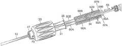
図1を参照すると、本発明の一部の実施形態では、ガイドシースアセンブリ10は、細長い可撓性シース12、及びシース12の近位側に位置する制御ハンドル16を含む。シース12は、近位部分13と遠位偏向部分14とを含む。制御ハンドル16は、例えば偏向部分14を含む、シース12上に支持された1つ又は2つ以上のリング電極19によって感知される電気信号を送信するための電気コネクタ17に接続することができる。図1に示されるように、制御ハンドル16には、ガイドシースアセンブリ10の中央管腔22を通じて進めることができるカテーテル(図に示されていない)を受容するように構成された止血バルブ18も取り付けられている(図1を修正)。止血バルブ18は、ガイドシースアセンブリ10の管腔22内に管腔22を通じて液体を供給するように1つ又は2つ以上の液体源(図に示されていない)に接続するため、例えば2方向ストップコック23のようなルアーハブで終端する側部ポート21も有する。 Referring to FIG. 1, in some embodiments of the present invention,
図2及び図3に示されるように、制御ハンドル16は、より幅の狭い遠位部分すなわち軸部25を有する細長いほぼ円筒状の本体24を含み、遠位部の軸部25には、遠位回転制御ノブ26が取り付けられている。本体24は、内部容積Vを画定するように形成された外側シェル半部材を有し、その縁部51同士は長手方向シームに沿って合わされるようになっている。本体の遠位軸部25は、本体24の近位部分の外径D2と比較してより小さい外径D1を有する。制御ノブ26は、使用者が制御ハンドル16の本体24を把持する際に使用者の親指と人差し指とによって回転させられるように構成されている。第1及び第2のプルワイア30A及び30Bによるガイドシース12の偏向部分14の偏向を可能とするため、制御ハンドル16は、その内部容積V内に回転式シャフト31、第1及び第2のシャトル32A及び32B、並びにピニオン34を含む。回転式シャフト31は、制御ノブ26に反応して第1のシャトル32Aを駆動して長手方向軸55に沿って第1の方向に直線的に動かし、ピニオン34が第2のシャトル32Bを第1のシャトル32Aと連結していることにより、第2のシャトル32Bは第1の方向とは逆の第2の方向に長手方向軸に沿って直線的に動くようになっている。第1及び第2のプルワイア30A及び30Bの各近位端は、第1及び第2のシャトル32A及び32Bにそれぞれ固定、又は少なくとも連結されているため、このような第1及び第2のシャトルの連動した逆方向の並進運動は、第1及び第2のプルワイアを作動してガイドシース12の偏向部分14の2方向への偏向を生じさせる。 As shown in FIGS. 2 and 3, the
回転式シャフト31は、外径D3を有する主近位部分36、外径D4を有するより短い遠位部分37、及び部分36と部分37との間の段差接続部Jを有する。図に示される実施形態では、直径D3は直径D4より大きくなっているが、2つの直径がほぼ等しくともよく、又は直径D4が直径D3よりも大きくてもよいことは理解されよう。図2により分かりやすく示されるように、回転式シャフト31は、その近位部分36が、制御ハンドル16の本体24及び遠位軸部25の両方を通り、遠位軸部25の遠位端を超えて延びるように制御ハンドル16の本体24に対して配置されており、接続部J及び遠位部分37が本体24の遠位軸部25の遠位側に位置しているために、遠位部分37は遠位軸部25によって包囲されていない。回転式シャフト31は、その近位端において、本体24の内部容積V内に形成された周方向フランジ40の間に画定された内側周方向スロットと嵌合する近位外側周方向リップ38によって本体24に連結及び固着されている。 The
図4を参照すると、回転式シャフト31は内側通路42を有する中空である。通路42は、ガイドシース12の直径よりもほんのわずかに大きい直径を有する遠位入口44と連通している。通路42は螺刻されており、下記に更に詳しく述べるように、ガイドシース12並びにガイドシース12を周方向に包囲するシャトル32A及び32Bの両方を収容するような直径を有する。 Referring to FIG. 4,
制御ノブ26は、制御ハンドル16の本体24の遠位軸部25及び回転式シャフト31に取り付けられ、主近位部分46と短い遠位端部分47とを有する。制御ノブ26は、その全長を通じて延びる長手方向の中空内部を有するほぼ円筒状をなしている。中空内部は、主近位部分49、中間部分49’、及び遠位部分49’’を有する。中空内部の主近位部分49は、ガイドシース12とシャトル32A及び32Bとを収容し、その周囲を包囲する、より大きな第1の半径R1とより大きな第1の長さL1とによって規定される。中空内部の遠位部分49’’は、ガイドシース12と回転式シャフト31の遠位部分37とを収容し、その周囲を包囲する、より小さい第2の半径R2(R1>R2)とより小さい第2の長さL2(L1>L1)とによって規定される。中空内部の中間部分49’は、ガイドシース12と回転式シャフト31の接続部Jとを収容し、その周囲を包囲する第3の半径R3(R1>R3>R2)と第3の長さL3(L1>L3)とによって規定される。制御ノブ26の外側表面上には、使用者が制御ノブを操作し、制御ハンドル16の本体24に対して制御ノブを回転させることを容易かつ快適に行えるように摩擦発生カバー60を取り付けることができる。
回転式シャフト31を制御ノブ26に回転可能に連結するため、シャフトの遠位部分の外側表面は長手方向の隆起部70(図3)を有し、これが制御ノブ26の中空内部49’’を画定する内側表面に形成された対応する長手方向凹部71(図4)に受容され、凹部71と嵌合するようになっている。制御ノブ26を回転式シャフト31、ひいては本体24に並進動可能に固着するため、シャフト31の外側表面は、回転式シャフト31の長手方向軸に対して垂直な向きの1つ又は2つ以上の直線状スロット74を更に有する。各スロット74を、制御ノブ26の遠位端部分47の側面を通じて形成された対応する穴76(図5)と位置合わせすることで、対応するピン77を穴76及びスロット74に挿入して制御ノブ26と回転式シャフト31とを連結することができる。 To rotatably connect the
ガイドシースアセンブリの他の実施形態は、制御ノブ26を用いずに使用者が直接操作できるように露出した部分を有する回転式シャフト31を提供することもできる点は理解されよう。 It will be appreciated that other embodiments of the guide sheath assembly may provide the
図3及び図5に示されるように、シャトル32A及び32Bは互いに似た構造を有しており、それぞれがほぼ他方の鏡像となっているという理解でよいが、第1のシャトル32Aは回転式シャフト31によって駆動され、第2のシャトル32Bはシャトルの間に配置されるピニオン34を介して第1のシャトル32Aによって駆動される。各シャトル32A及び32Bは、C字状の端部断面を有する遠位部分80A及び80Bを有するそれぞれの細長い本体と、複数の歯92A及び92Bが長手方向にそれぞれ配列されたそれぞれの近位ラック部分90A及び90Bと、を有する。第1のシャトルと第2のシャトルとは互いに対向して配置されてピニオン34と噛合することにより、遠位部分80Aと遠位部分80Bとが、螺刻通路42内に嵌まる外周面と、ガイドシース12が通される通路93を画定する内周面とを有する円筒状の形態を互いに形成することができる。図5に示されるように、各シャトルのラック部分90Aと90Bとは、ピニオン34を間に挟んで互いに対向しており、各ラック部分の歯92A及び92Bが、制御ハンドル16の長手方向軸55に対して垂直な軸を中心として回転するように取り付けられたピニオン34の歯と噛合できるようになっている。 As shown in FIGS. 3 and 5, the
図2及び図3を参照すると、第1のシャトル32Aの遠位部分80Aの外側表面には、外側又は雄ねじ螺刻面85が設けられている。回転式シャフト31の内周面には第1のシャトル32Aの雄ねじ螺刻面85を受容する内側又は雌ねじ螺刻面86が設けられており(図4)、これにより第1のシャトル32Aと回転式シャフト31とが連結され、回転式シャフト31の回転運動が第1のシャトル32Aの並進運動に変換される。これに対して、第2のシャトル32Bの遠位部分80Bの外側表面は滑らかで、回転式シャフト31の雌ねじ螺刻面と噛合する何らの機構も設けられていないため、雄ねじ螺刻面85とは独立して動くことができる。したがって、使用者が制御ノブ26を第1の方向に回転させると、長手方向の隆起部70を介して制御ノブ26と回転可能に連結された回転式シャフト31も回転する。回転式シャフト31は長手方向の隆起部70、及び1つ又は2つ以上のピン77を介して制御ノブ26に回転可能かつ並進動可能にロックされているため、シャフト31の回転は、第1のシャトル32Aを駆動して長手方向軸に沿って第1の方向(例えば近位方向)に並進運動させる。第1のシャトル32Aが並進運動すると、その歯92Aがピニオン34を駆動して第1の方向(例えば時計回り)に回転させ、ピニオン34は第2のシャトル32Bを駆動して長手方向軸55に沿って第1の方向とは反対の第2の方向(例えば遠位方向)に並進運動させる。このような構成により、雄ねじ螺刻面85と雌ねじ螺刻面86とが、制御ノブ26の回転運動をシャトル32A及び32Bの直線運動に変換する。第1及び第2のプルワイア30A及び30Bの各近位端は第1及び第2のシャトル32A及び32Bにそれぞれ固定、連結されるか、又は他の形で反応するようになっているため、シャトルの直線的かつ逆方向の運動はプルワイアを作動してガイドシース12の偏向部分14の2方向への偏向を生じさせる。図の実施形態では、プルワイア30A及び30Bの各近位端は、シャトル32A及び32Bのラック部分90A及び90Bにそれぞれ連結されている。これにより、一方のプルワイアがその対応するシャトルによって張力下で近位方向に引かれると、他方のプルワイアは遠位方向に移動するその対応するシャトルによって同時に張力から解放される。 2 and 3, the outer surface of the
図2に示されるように、各プルワイア30A及び30Bの近位端部分は、各シャトル32A及び32Bの近位ラック部分90A及び90Bに形成された、対応する長手方向の溝88A及び88B内で、シース12の外部に延びている。図5に示されるように、各プルワイア30A及び30Bの近位端には例えばハイポチューブのような係止要素89A及び89Bが固着されており、この係止要素がそれぞれのラック部分90A及び90Bの近位端87A及び87Bの近位に位置付けられることにより、シャトル32A及び32Bが近位方向に動かされると、ラック部分が係止要素89A及び89Bをそれぞれ押すか又は他の形でこれに作用してプルワイア30A及び30Bを近位方向に引くことができる。シャトル32A及び32Bが遠位方向に動かされると、ラック部分90A及び90Bの近位端は係止要素89A及び89Bとの接触状態から外れ、プルワイア30A及び30Bが張力から解放される。係止要素89A及び89Bは、シースを偏向させるためにラック部分又はシャトルの任意の部分に埋め込むか又は他の形で固定されてもよい点は理解されよう。 As shown in FIG. 2, the proximal end portions of each pullwire 30A and 30B are positioned within corresponding
第1のシャトル32Aと第2のシャトル32Bとは長手方向軸55に沿って反対方向に動くことから、シャトル同士の互い及び通路42に対する初期の位置決めは制御ハンドルの組み立て時に行われる。例えば図2に示されるように、各シャトルが長手方向軸55に沿って互いに揃うように回転式シャフト31の通路42内に位置付けられると、それぞれのシャトルの遠位端は通路42に沿ってほぼ中間点に位置付けられるため、各シャトルは回転式シャフト31内で近位方向又は遠位方向に対応して動くのに充分な空間を有することになる。ほとんど偏向しないほぼニュートラルなガイドシースでは、係止要素89A及び89Bは、各プルワイア30A及び30Bに作用する張力が最小又は均一となるように、各シャトルに対して位置付けることができる。このような構成では、シャトルは、「ニュートラルな」、すなわち、使用者がガイドシースをそこから2方向に均一に偏向させることができる初期形態をとる。 Since the
図5に示されるように、ピニオン34は、シャトルが使用者による制御ノブ26の操作に応じて並進運動する間、シャトルの歯92A及び92Bが係合した状態に保たれるように、シャトル32Aと32Bとの間にかつシャトル32A及び32Bに対して位置付けられている。この点に関して、ラック部分90A及び90Bの長さは、そのような連続的な係合を確実とするうえで充分な長さとなっている。 As shown in FIG. 5,
例えば、通路42の長さ、各遠位部分80A及び80Bの長さ、ラック部分90A及び90Bの長さ、ピニオン34の位置、並びにピニオンの数などの1つ又は2つ以上の因子を変えることにより、異なるシャトルの動き及び偏向特性並びに制限を、必要に応じ又は所望に応じて実現することができる点は理解されよう。 For example, varying one or more factors such as the length of
図6A及び6Bを参照すると、各シャトル32A及び32Bの歯92A及び92Bの反対側の、各ラック部分90A及び90Bの外側表面には、ニュートラル指示機構が設けられている。ニュートラル指示機構は、第1のシャトル32Aと第2のシャトル32Bとの間のニュートラル位置、すなわち、プルワイア30A及び30Bがニュートラルにあり、それによりガイドシース12が偏向せずにほぼ真っ直ぐであるような相対位置を示すために、互いに解放可能に嵌合するように構成された第1の部材62Aと第2の部材62Bとを有している。図の実施形態では、第1のシャトル32Aに形成された第1の、すなわち雄型部材62Aは、第2のシャトル32Bに形成された第2の、すなわち雌型部材62Bに対向したテーパ状突起部63を有しており、第2の部材62Bは、両側の一対の可撓性ガイドレール64を含み、ガイドレール64の固定端65は第2のシャトル32Bに固着されており、ガイドレール64の自由端66は、シャトル32A及び32Bがニュートラル形態にある場合にその中にテーパ状突起部63が収まるテーパ状凹部67を共に形成するように構成されている。 6A and 6B, a neutral indicating feature is provided on the outer surface of each
したがって、使用者には、一般的には最初にガイドシース12が偏向していない状態で与えられ、この状態では、図6Aに示されるように、テーパ状突起部63がテーパ状凹部67内に収まった状態で、第1のシャトル32Aと第2のシャトル32Bとが互いに対して揃っている。使用者が図6Bに示されるように制御ノブ26を、第1のシャトル32Aと第2のシャトル32Bとを反対方向に並進運動させるように駆動する一方向に回転させると、テーパ状突起部63がテーパ状凹部67から外れてテーパ状凹部67の外へと動くが、そのためには、使用者は、ガイドレール64を撓ませてその角度が付けられた端部68によって与えられる抵抗に打ち勝つだけの充分な力で制御ノブを回転させなければならない。テーパ状突起部63が、角度が付けられた端部68の一方を乗り越えてこれを通過すると、テーパ状突起部63がテーパ状凹部67からより遠くへと動くのに従ってテーパ状突起部63の運動に対する抵抗が小さくなるように、ガイドレール64が傾斜している。このため、ガイドシース12を偏向させるために制御ノブ26を回転させる際、使用者は、シャトル32A及び32Bが最初にニュートラル形態から動き出す際により大きい、又は最大の抵抗を感じ、その後、シャトル32Aと32Bとが反対方向に並進運動するに従って次第に動かしやすさを感じる。制御ハンドル16は、偏向方向の一定の向きを与えるための視覚的及び/又は触覚的標示を有してもよい。例えば、制御ノブ26の時計回りの回転は、シャフト12を側面に向かって、すなわち側部ポート21の方向に一貫して偏向させ、制御ノブ26の反時計回りの回転は、シャフト12を反対の側面又は方向に向かって偏向させる。 Accordingly, the user is typically initially presented with the
逆に、ガイドシース12の偏向を解除する際、使用者は制御ノブ26を反対方向に回転させる。シャトル32Aと32Bとが並進運動して互いに近づき、横方向に再び位置が揃い始めると、テーパ状突起部63とテーパ状凹部67とが互いに近づき、使用者は、テーパ状突起部63がテーパ状凹部67内に収まりうる前にガイドレール64の角度が付けられた端部68を再び乗り越えるように、制御ノブ26を回転させるためにより大きな力を加えることになる。したがって、傾斜したレール64のいずれかによって与えられる増大する抵抗と、角度が付けられた端部68によって与えられるより大きな、又は最大の抵抗は、テーパ状突起部63がテーパ状凹部67に近接したことの触覚的感覚又は指示を使用者に与えるものである。テーパ状突起部63とテーパ状凹部67との嵌合は、使用者に、テーパ状突起部63によって可撓性ガイドレール64に対して負荷が加えられなくなった時点でガイドレール64がその自然な形態に跳ね返る際に耳に聞こえる「カチッ」という音又はシグナルを与えることができる。 Conversely, to undeflect
上記の説明は、現時点における本発明の好ましい実施形態に関連して示したものである。本発明が関連する分野及び技術の当業者であれば、本発明の原理、趣旨、及び範囲を大きく逸脱することなく、記載される構造に改変及び変更を実施しうる点は認識されるであろう。1つの実施形態に開示される任意の特徴又は構造は、必要に応じて又は適宜、他の任意の実施形態の他の特徴に代えて、又はそれに加えて組み込むことができる。当業者には理解されるように、図面は必ずしも縮尺どおりではない。したがって、上記の説明文は、添付図面に記載及び例示される正確な構成のみに関連したものとして読まれるべきではなく、むしろ以下の最も完全で公正な範囲を有するものとされる特許請求の範囲と一致し、かつこれを支持するものとして読まれるべきである。 The above description has been presented in connection with presently preferred embodiments of the invention. Those skilled in the art and technology to which the present invention pertains will appreciate that modifications and variations can be made in the structure described without departing substantially from the principle, spirit and scope of the invention. deaf. Any feature or structure disclosed in one embodiment may be incorporated in place of or in addition to other features of any other embodiment as desired or appropriate. As will be appreciated by those skilled in the art, the drawings are not necessarily to scale. Therefore, the above description should not be read as relating solely to the precise configurations shown and illustrated in the accompanying drawings, but rather the following claims, which are given their fullest and fairest scope: should be read as consistent with and in support of
〔実施の態様〕
(1) ガイドシースアセンブリであって、
細長いシャフトと、
前記シャフトの近位に位置する制御ハンドルであって、長手方向軸を有し、かつ
前記制御ハンドルの長手方向軸を中心として回転するように構成された回転式シャフトと、
前記回転式シャフトの回転に反応して前記長手方向軸に沿って一方向に並進運動するように構成された第1のシャトルであって、第1の複数の歯を有する、第1のシャトルと、
前記第1の複数の歯と噛合するピニオンであって、前記第1のシャトルの並進運動に反応して前記長手方向軸に対してほぼ垂直な軸を中心として回転するように構成された、ピニオンと、
前記ピニオンと噛合する第2の複数の歯を有する第2のシャトルであって、前記ピニオンの回転に反応して前記長手方向軸に沿って前記一方向と反対の別の方向に並進運動するように構成された、第2のシャトルと、を含む、制御ハンドルと、を備え、
前記ガイドシースアセンブリは、
前記シャフトの一側面に沿って延びる第1のプルワイアであって、前記第1のシャトルの近位方向への並進運動に少なくとも反応する近位端部分を有する、第1のプルワイアと、
前記シャフトの別の側面に沿って延びる第2のプルワイアであって、前記第2のシャトルの前記近位方向への並進運動に少なくとも反応する近位端部分を有する、第2のプルワイアと、を更に備える、ガイドシースアセンブリ。
(2) 前記制御ハンドルが制御ノブを含み、前記回転式シャフトが、前記制御ノブの回転に反応して回転するように構成されている、実施態様1に記載のガイドシースアセンブリ。
(3) 前記回転式シャフトが内側通路を有し、前記第1のシャトルの第1の遠位部分と前記第2のシャトルの第2の遠位部分とが両方とも前記内側通路内に延びる、実施態様1に記載のガイドシースアセンブリ。
(4) 前記第1及び第2の遠位部分は、前記第1のシャトルと前記第2のシャトルとが前記長手方向軸に沿って横方向に互いに対して揃う際に、円筒状の形態を形成するように構成されている、実施態様3に記載のガイドシースアセンブリ。
(5) 前記内側通路の内側表面が螺刻され、前記第1の遠位部分の外側表面が螺刻されて前記内側表面と係合されている、実施態様3に記載のガイドシースアセンブリ。[Mode of implementation]
(1) A guide sheath assembly comprising:
an elongated shaft and
a control handle proximal to the shaft, the rotatable shaft having a longitudinal axis and configured to rotate about the longitudinal axis of the control handle;
a first shuttle configured to translate in one direction along the longitudinal axis in response to rotation of the rotatable shaft, the first shuttle having a first plurality of teeth; ,
A pinion in mesh with the first plurality of teeth, the pinion configured to rotate about an axis substantially perpendicular to the longitudinal axis in response to translational movement of the first shuttle. When,
a second shuttle having a second plurality of teeth meshing with said pinion for translational movement along said longitudinal axis in another direction opposite said one direction in response to rotation of said pinion; a control handle including a second shuttle configured to
The guide sheath assembly includes:
a first pullwire extending along one side of the shaft, the first pullwire having a proximal end portion that is at least responsive to proximal translational movement of the first shuttle;
a second pullwire extending along another side of the shaft, the second pullwire having a proximal end portion that is at least responsive to the proximal translation of the second shuttle; Further comprising a guide sheath assembly.
Clause 2. The guide sheath assembly of clause 1, wherein the control handle includes a control knob and the rotatable shaft is configured to rotate in response to rotation of the control knob.
(3) the rotatable shaft has an inner passageway, and a first distal portion of the first shuttle and a second distal portion of the second shuttle both extend into the inner passageway; A guide-sheath assembly according to claim 1.
(4) said first and second distal portions assume a cylindrical configuration when said first shuttle and said second shuttle are laterally aligned with respect to each other along said longitudinal axis; 4. The guide-sheath assembly of embodiment 3, wherein the guide-sheath assembly is configured to form:
Clause 5. The guide sheath assembly of clause 3, wherein an inner surface of the inner passageway is threaded and an outer surface of the first distal portion is threaded into engagement with the inner surface.
(6) 前記回転式シャフトが、前記制御ノブと回転可能かつ並進運動可能に連結されている、実施態様1に記載のガイドシースアセンブリ。
(7) 前記回転式シャフトが、前記シャフトの外側表面に形成された長手方向の隆起部によって前記制御ノブと回転可能に連結されている、実施態様6に記載のガイドシースアセンブリ。
(8) 前記回転式シャフトが、前記制御ノブの一部を通じて延びるピンと、前記回転式シャフトに形成されたスロットとによって、前記制御ノブと回転可能に連結されている、実施態様6に記載のガイドシースアセンブリ。
(9) 前記回転式シャフトが、前記制御ノブとその遠位端において回転可能かつ並進運動可能に連結されている、実施態様6に記載のガイドシースアセンブリ。
(10) 前記制御ハンドルが、ニュートラル指示機構を含む、実施態様1に記載のガイドシースアセンブリ。Clause 6. The guide sheath assembly of clause 1, wherein the rotatable shaft is rotatably and translatably coupled to the control knob.
Clause 7. The guide sheath assembly of clause 6, wherein the rotatable shaft is rotatably coupled to the control knob by longitudinal ridges formed on the outer surface of the shaft.
8. The guide of claim 6, wherein the rotatable shaft is rotatably coupled to the control knob by a pin extending through a portion of the control knob and a slot formed in the rotatable shaft. sheath assembly.
Clause 9. The guide-sheath assembly of clause 6, wherein the rotatable shaft is rotatably and translatably coupled to the control knob at its distal end.
(11) 前記ニュートラル指示機構が、前記第1のシャトル上の第1の部材と、前記第2のシャトル上の第2の部材とを含み、前記第1の部材及び前記第2の部材は、解放可能に嵌合するように構成されている、実施態様10に記載のガイドシースアセンブリ。
(12) 前記ニュートラル指示機構が、係脱及び再嵌合に対して抵抗をもたらすように構成されている、実施態様10に記載のガイドシースアセンブリ。
(13) 前記ニュートラル指示機構の前記第1の部材がテーパ状突起部を含み、前記ニュートラル指示機構の前記第2の部材がテーパ状凹部を含む、実施態様11に記載のガイドシースアセンブリ。
(14) ガイドシースアセンブリであって、
細長いシャフトと、
前記シャフトの近位に位置する制御ハンドルであって、長手方向軸を有し、かつ
前記長手方向軸を中心として回転するように構成された制御ノブと、
前記制御ノブの回転に反応して前記長手方向軸を中心として回転するように構成された中空回転式シャフトと、
前記回転式シャフトの回転に反応して前記長手方向軸に沿って一方向に並進運動するように構成された第1のシャトルであって、第1の複数の歯を有する、第1のシャトルと、
前記第1の複数の歯と噛合するピニオンであって、前記第1のシャトルの並進運動に反応して前記長手方向軸に対してほぼ垂直な軸を中心として回転するように構成された、ピニオンと、
前記ピニオンと噛合する第2の複数の歯を有する第2のシャトルであって、前記ピニオンの回転に反応して前記長手方向軸に沿って前記一方向と反対の別の方向に並進運動するように構成された、第2のシャトルと、を含む、制御ハンドルと、を備え、
前記ガイドシースアセンブリは、
前記シャフトの一側面に沿って延びる第1のプルワイアであって、前記第1のシャトルの近位方向への並進運動に少なくとも反応する近位端部分を有する、第1のプルワイアと、
前記シャフトの別の側面に沿って延びる第2のプルワイアであって、前記第2のシャトルの前記近位方向への並進運動に少なくとも反応する近位端部分を有する、第2のプルワイアと、を更に備える、ガイドシースアセンブリ。
(15) 前記第1及び第2のシャトルの遠位端が、前記回転式シャフトの近位部分内に延びる、実施態様14に記載のガイドシースアセンブリ。(11) said neutral indicating mechanism includes a first member on said first shuttle and a second member on said second shuttle, said first member and said second member comprising: 11. The guide sheath assembly of
(14) A guide sheath assembly comprising:
an elongated shaft and
a control handle proximal to the shaft, the control knob having a longitudinal axis and configured to rotate about the longitudinal axis;
a hollow rotatable shaft configured to rotate about the longitudinal axis in response to rotation of the control knob;
a first shuttle configured to translate in one direction along the longitudinal axis in response to rotation of the rotatable shaft, the first shuttle having a first plurality of teeth; ,
A pinion in mesh with the first plurality of teeth, the pinion configured to rotate about an axis substantially perpendicular to the longitudinal axis in response to translational movement of the first shuttle. When,
a second shuttle having a second plurality of teeth meshing with said pinion for translational movement along said longitudinal axis in another direction opposite said one direction in response to rotation of said pinion; a control handle including a second shuttle configured to
The guide sheath assembly includes:
a first pullwire extending along one side of the shaft, the first pullwire having a proximal end portion that is at least responsive to proximal translation of the first shuttle;
a second pullwire extending along another side of the shaft, the second pullwire having a proximal end portion that is at least responsive to the proximal translation of the second shuttle; Further comprising a guide sheath assembly.
Clause 15. The guide-sheath assembly of clause 14, wherein distal ends of said first and second shuttles extend into a proximal portion of said rotatable shaft.
(16) 前記回転式シャフトの内側表面が螺刻され、前記第1のシャトルの外側表面が、前記回転式シャフトと前記第1のシャトルとを回転可能に連結するために螺刻されている、実施態様15に記載のガイドシースアセンブリ。
(17) 医療用ガイドシースシャフトの偏向を制御するために使用される制御ハンドルであって、長手方向軸を有し、かつ
前記長手方向軸を中心として回転するように構成された制御ノブと、
前記制御ノブの回転に反応して前記長手方向軸を中心として回転するように構成された中空回転式シャフトと、
前記回転式シャフトの回転に反応して前記長手方向軸に沿って一方向に並進運動するように構成された第1のシャトルであって、第1の複数の歯を有する、第1のシャトルと、
前記第1の複数の歯と噛合するピニオンであって、前記第1のシャトルの並進運動に反応して前記長手方向軸に対してほぼ垂直な軸を中心として回転するように構成された、ピニオンと、
前記ピニオンと噛合する第2の複数の歯を有する第2のシャトルであって、前記ピニオンの回転に反応して前記長手方向軸に沿って前記一方向と反対の別の方向に並進運動するように構成された、第2のシャトルと、を含み、
前記第1及び第2のシャトルは、前記ガイドシースシャフトに沿って延びる第1及び第2のプルワイアに対してそれぞれ作用するように構成されている、制御ハンドル。
(18) 前記第1及び第2のシャトルの遠位端が、前記回転式シャフトの近位部分内に延びる、実施態様17に記載の制御ハンドル。
(19) 前記回転式シャフトの内側表面が螺刻され、前記第1のシャトルの外側表面が、前記回転式シャフトと前記第1のシャトルとを回転可能に連結するために螺刻されている、実施態様18に記載の制御ハンドル。
(20) 前記第1のシャトルが前記回転式シャフトの回転に直接反応し、前記第2のシャトルが前記ピニオンの回転に直接反応する、実施態様17に記載の制御ハンドル。(16) an inner surface of the rotatable shaft is threaded and an outer surface of the first shuttle is threaded to rotatably couple the rotatable shaft and the first shuttle; 16. A guide-sheath assembly according to embodiment 15.
(17) a control handle used to control the deflection of the medical guide sheath shaft, the control knob having a longitudinal axis and configured to rotate about the longitudinal axis;
a hollow rotatable shaft configured to rotate about the longitudinal axis in response to rotation of the control knob;
a first shuttle configured to translate in one direction along the longitudinal axis in response to rotation of the rotatable shaft, the first shuttle having a first plurality of teeth; ,
A pinion in mesh with the first plurality of teeth, the pinion configured to rotate about an axis substantially perpendicular to the longitudinal axis in response to translational movement of the first shuttle. When,
a second shuttle having a second plurality of teeth meshing with said pinion for translational movement along said longitudinal axis in another direction opposite said one direction in response to rotation of said pinion; a second shuttle configured to
A control handle, wherein the first and second shuttles are configured to act respectively on first and second pull wires extending along the guide sheath shaft.
(19) an inner surface of the rotatable shaft is threaded and an outer surface of the first shuttle is threaded to rotatably couple the rotatable shaft and the first shuttle; 19. A control handle according to
20. The control handle of
Claims (17)
Translated fromJapanese細長いシャフトと、
前記シャフトの近位に位置する制御ハンドルであって、長手方向軸を有し、かつ
前記制御ハンドルの長手方向軸を中心として回転するように構成された回転式シャフトと、
前記回転式シャフトの回転に反応して前記長手方向軸に沿って一方向に並進運動するように構成された第1のシャトルであって、第1の複数の歯を有する、第1のシャトルと、
前記第1の複数の歯と噛合するピニオンであって、前記第1のシャトルの並進運動に反応して前記長手方向軸に対してほぼ垂直な軸を中心として回転するように構成された、ピニオンと、
前記ピニオンと噛合する第2の複数の歯を有する第2のシャトルであって、前記ピニオンの回転に反応して前記長手方向軸に沿って前記一方向と反対の別の方向に並進運動するように構成された、第2のシャトルと、を含む、制御ハンドルと、を備え、
前記ガイドシースアセンブリは、
前記シャフトの一側面に沿って延びる第1のプルワイアであって、前記第1のシャトルの近位方向への並進運動に少なくとも反応する近位端部分を有する、第1のプルワイアと、
前記シャフトの別の側面に沿って延びる第2のプルワイアであって、前記第2のシャトルの前記近位方向への並進運動に少なくとも反応する近位端部分を有する、第2のプルワイアと、を更に備え、
前記制御ハンドルが制御ノブを含み、前記回転式シャフトが、前記制御ノブの回転に反応して回転するように構成されており、
前記回転式シャフトが前記制御ノブと共に回転可能なように、前記回転式シャフトが前記制御ノブに連結されるように構成されており、
前記回転式シャフトが前記制御ノブと位置合わせされることができるように、前記回転式シャフトの外側表面に形成された長手方向の隆起部が、前記制御ノブに形成された長手方向凹部に摺動可能に受容されるように構成されており、
前記制御ノブの一部を通って延びるピンが前記回転式シャフトに形成されたスロットに挿入された際に、前記回転式シャフトが前記制御ノブと連結されるように構成されている、ガイドシースアセンブリ。A guide sheath assembly comprising:
an elongated shaft and
a control handle proximal to the shaft, the rotatable shaft having a longitudinal axis and configured to rotate about the longitudinal axis of the control handle;
a first shuttle configured to translate in one direction along the longitudinal axis in response to rotation of the rotatable shaft, the first shuttle having a first plurality of teeth; ,
A pinion in mesh with the first plurality of teeth, the pinion configured to rotate about an axis substantially perpendicular to the longitudinal axis in response to translational movement of the first shuttle. When,
a second shuttle having a second plurality of teeth meshing with said pinion for translational movement along said longitudinal axis in another direction opposite said one direction in response to rotation of said pinion; a control handle including a second shuttle configured to
The guide sheath assembly includes:
a first pullwire extending along one side of the shaft, the first pullwire having a proximal end portion that is at least responsive to proximal translation of the first shuttle;
a second pullwire extending along another side of the shaft, the second pullwire having a proximal end portion that is at least responsive to the proximal translation of the second shuttle; further prepared,
wherein the control handle includes a control knob, the rotatable shaft is configured to rotate in response to rotation of the control knob;
configured to couple the rotatable shaft to the control knob such that the rotatable shaft is rotatable with the controlknob;
A longitudinal ridge formed on an outer surface of the rotatable shaftslides into a longitudinal recess formed in the control knobsuch that the rotatable shaft can be aligned with the control knob.configured to be acceptable,
A guide sheath assemblyconfigured to couple the rotatable shaft with the control knob when a pin extendingthrough a portion of the control knobis inserted into a slot formedin the rotatable shaft. .
細長いシャフトと、
前記シャフトの近位に位置する制御ハンドルであって、長手方向軸を有し、かつ
前記長手方向軸を中心として回転するように構成された制御ノブと、
前記制御ノブの回転に反応して前記長手方向軸を中心として回転するように構成された回転式シャフトと、
前記回転式シャフトの回転に反応して前記長手方向軸に沿って一方向に並進運動するように構成された第1のシャトルであって、第1の複数の歯を有する、第1のシャトルと、
前記第1の複数の歯と噛合するピニオンであって、前記第1のシャトルの並進運動に反応して前記長手方向軸に対してほぼ垂直な軸を中心として回転するように構成された、ピニオンと、
前記ピニオンと噛合する第2の複数の歯を有する第2のシャトルであって、前記ピニオンの回転に反応して前記長手方向軸に沿って前記一方向と反対の別の方向に並進運動するように構成された、第2のシャトルと、を含む、制御ハンドルと、を備え、
前記ガイドシースアセンブリは、
前記シャフトの一側面に沿って延びる第1のプルワイアであって、前記第1のシャトルの近位方向への並進運動に少なくとも反応する近位端部分を有する、第1のプルワイアと、
前記シャフトの別の側面に沿って延びる第2のプルワイアであって、前記第2のシャトルの前記近位方向への並進運動に少なくとも反応する近位端部分を有する、第2のプルワイアと、を更に備えており、
前記回転式シャフトが前記制御ノブと共に回転可能なように、前記回転式シャフトが前記制御ノブに連結されるように構成されており、
前記回転式シャフトが前記制御ノブと位置合わせされることができるように、前記回転式シャフトの外側表面に形成された長手方向の隆起部が、前記制御ノブに形成された長手方向凹部に摺動可能に受容されるように構成されており、
前記制御ノブの一部を通って延びるピンが前記回転式シャフトに形成されたスロットに挿入された際に、前記回転式シャフトが前記制御ノブと連結されるように構成されている、ガイドシースアセンブリ。A guide sheath assembly comprising:
an elongated shaft and
a control handle proximal to the shaft, the control knob having a longitudinal axis and configured to rotate about the longitudinal axis;
a rotatable shaft configured to rotate about the longitudinal axis in response to rotation of the control knob;
a first shuttle configured to translate in one direction along the longitudinal axis in response to rotation of the rotatable shaft, the first shuttle having a first plurality of teeth; ,
A pinion in mesh with the first plurality of teeth, the pinion configured to rotate about an axis substantially perpendicular to the longitudinal axis in response to translational movement of the first shuttle. When,
a second shuttle having a second plurality of teeth meshing with said pinion for translational movement along said longitudinal axis in another direction opposite said one direction in response to rotation of said pinion; a control handle including a second shuttle configured to
The guide sheath assembly includes:
a first pullwire extending along one side of the shaft, the first pullwire having a proximal end portion that is at least responsive to proximal translation of the first shuttle;
a second pullwire extending along another side of the shaft, the second pullwire having a proximal end portion that is at least responsive to the proximal translation of the second shuttle; It is also equippedwith
configured to couple the rotatable shaft to the control knob such that the rotatable shaft is rotatable with the controlknob;
A longitudinal ridge formed on an outer surface of the rotatable shaftslides into a longitudinal recess formed in the control knobsuch that the rotatable shaft can be aligned with the control knob.configured to be acceptable,
A guide sheath assemblyconfigured to couple the rotatable shaft with the control knob when a pin extendingthrough a portion of the control knobis inserted into a slot formedin the rotatable shaft. .
前記長手方向軸を中心として回転するように構成された制御ノブと、
前記制御ノブの回転に反応して前記長手方向軸を中心として回転するように構成された回転式シャフトと、
前記回転式シャフトの回転に反応して前記長手方向軸に沿って一方向に並進運動するように構成された第1のシャトルであって、第1の複数の歯を有する、第1のシャトルと、
前記第1の複数の歯と噛合するピニオンであって、前記第1のシャトルの並進運動に反応して前記長手方向軸に対してほぼ垂直な軸を中心として回転するように構成された、ピニオンと、
前記ピニオンと噛合する第2の複数の歯を有する第2のシャトルであって、前記ピニオンの回転に反応して前記長手方向軸に沿って前記一方向と反対の別の方向に並進運動するように構成された、第2のシャトルと、を含み、
前記第1及び第2のシャトルは、前記医療用ガイドシースシャフトに沿って延びる第1及び第2のプルワイアに対してそれぞれ作用するように構成されており、
前記回転式シャフトが前記制御ノブと共に回転可能なように、前記回転式シャフトが前記制御ノブに連結されるように構成されており、
前記回転式シャフトが前記制御ノブと位置合わせされることができるように、前記回転式シャフトの外側表面に形成された長手方向の隆起部が、前記制御ノブに形成された長手方向凹部に摺動可能に受容されるように構成されており、
前記制御ノブの一部を通って延びるピンが前記回転式シャフトに形成されたスロットに挿入された際に、前記回転式シャフトが前記制御ノブと連結されるように構成されている、制御ハンドル。a control handle used to control deflection of a medical guide sheath shaft, the control knob having a longitudinal axis and configured to rotate about the longitudinal axis;
a rotatable shaft configured to rotate about the longitudinal axis in response to rotation of the control knob;
a first shuttle configured to translate in one direction along the longitudinal axis in response to rotation of the rotatable shaft, the first shuttle having a first plurality of teeth; ,
A pinion in mesh with the first plurality of teeth, the pinion configured to rotate about an axis substantially perpendicular to the longitudinal axis in response to translational movement of the first shuttle. When,
a second shuttle having a second plurality of teeth meshing with said pinion for translational movement along said longitudinal axis in another direction opposite said one direction in response to rotation of said pinion; a second shuttle configured to
the first and second shuttles are configured to act respectively on first and second pull wires extending along the medical guide sheath shaft;
configured to couple the rotatable shaft to the control knob such that the rotatable shaft is rotatable with the controlknob;
A longitudinal ridge formed on an outer surface of the rotatable shaftslides into a longitudinal recess formed in the control knobsuch that the rotatable shaft can be aligned with the control knob.configured to be acceptable,
A control handleconfigured to couple the rotatable shaft with the control knob when a pin extendingthrough a portion of the control knobis inserted into a slot formedin the rotatable shaft.
Priority Applications (1)
| Application Number | Priority Date | Filing Date | Title |
|---|---|---|---|
| JP2022179442AJP7472236B2 (en) | 2016-12-07 | 2022-11-09 | Orientable guide sheath with rack and pinion deflection mechanism |
Applications Claiming Priority (2)
| Application Number | Priority Date | Filing Date | Title |
|---|---|---|---|
| US15/372,329US10653860B2 (en) | 2016-12-07 | 2016-12-07 | Steerable guiding sheath with rack and pinion deflection mechanism |
| US15/372,329 | 2016-12-07 |
Related Child Applications (1)
| Application Number | Title | Priority Date | Filing Date |
|---|---|---|---|
| JP2022179442ADivisionJP7472236B2 (en) | 2016-12-07 | 2022-11-09 | Orientable guide sheath with rack and pinion deflection mechanism |
Publications (2)
| Publication Number | Publication Date |
|---|---|
| JP2018094406A JP2018094406A (en) | 2018-06-21 |
| JP7175604B2true JP7175604B2 (en) | 2022-11-21 |
Family
ID=60661772
Family Applications (2)
| Application Number | Title | Priority Date | Filing Date |
|---|---|---|---|
| JP2017234022AActiveJP7175604B2 (en) | 2016-12-07 | 2017-12-06 | Orientable guide sheath with rack and pinion deflection mechanism |
| JP2022179442AActiveJP7472236B2 (en) | 2016-12-07 | 2022-11-09 | Orientable guide sheath with rack and pinion deflection mechanism |
Family Applications After (1)
| Application Number | Title | Priority Date | Filing Date |
|---|---|---|---|
| JP2022179442AActiveJP7472236B2 (en) | 2016-12-07 | 2022-11-09 | Orientable guide sheath with rack and pinion deflection mechanism |
Country Status (7)
| Country | Link |
|---|---|
| US (3) | US10653860B2 (en) |
| EP (1) | EP3332832B1 (en) |
| JP (2) | JP7175604B2 (en) |
| CN (1) | CN108159549B (en) |
| AU (1) | AU2017258874A1 (en) |
| CA (1) | CA2987763A1 (en) |
| IL (1) | IL255693A0 (en) |
Families Citing this family (21)
| Publication number | Priority date | Publication date | Assignee | Title |
|---|---|---|---|---|
| US10653860B2 (en) | 2016-12-07 | 2020-05-19 | Biosense Webster (Israel) Ltd. | Steerable guiding sheath with rack and pinion deflection mechanism |
| US20190038873A1 (en)* | 2017-08-04 | 2019-02-07 | Cryterion Medical, Inc. | Steering assembly for intravascular catheter system |
| CN109124594B (en)* | 2018-09-20 | 2021-05-11 | 广东健奥科技有限公司 | Safe type body temperature monitoring device |
| WO2020263742A1 (en)* | 2019-06-24 | 2020-12-30 | Medtronic, Inc. | Catheter handle with torque mechanism and valve relief component |
| WO2021026636A1 (en)* | 2019-08-15 | 2021-02-18 | North Star Specialists Inc. | Steerable catheter or sheath and method of use thereof |
| CN110575604A (en)* | 2019-10-14 | 2019-12-17 | 苏州法兰克曼医疗器械有限公司 | A medical device with an angle adjustment device |
| USD940306S1 (en)* | 2020-06-11 | 2022-01-04 | Oscor Inc. | Steerable catheter handle |
| USD940307S1 (en)* | 2020-06-11 | 2022-01-04 | Oscor Inc. | Steerable catheter handle |
| EP4167892A4 (en) | 2020-06-19 | 2024-10-30 | Remedy Robotics, Inc. | SYSTEMS AND METHODS FOR GUIDING INTRALUMINAL DEVICES WITHIN THE VASCULAR SYSTEM |
| US20220110577A1 (en)* | 2020-10-12 | 2022-04-14 | Biosense Webster (Israel) Ltd. | Guiding sheath with distal tip locator |
| US12083288B2 (en)* | 2020-12-02 | 2024-09-10 | Biosense Webster (Israel) Ltd. | One-motion handle for steerable catheter |
| US20220313961A1 (en)* | 2021-03-31 | 2022-10-06 | Biosense Webster (Israel) Ltd. | Electrophysiology devices with deflection detection |
| CN113208552A (en)* | 2021-05-24 | 2021-08-06 | 胡婷婷 | Hysteroscope |
| US20220379091A1 (en)* | 2021-05-28 | 2022-12-01 | Medtronic Vascular, Inc. | Steerable catheter device |
| US12121307B2 (en) | 2021-07-01 | 2024-10-22 | Remedy Robotics, Inc. | Vision-based position and orientation determination for endovascular tools |
| US11707332B2 (en) | 2021-07-01 | 2023-07-25 | Remedy Robotics, Inc. | Image space control for endovascular tools |
| EP4364163A1 (en) | 2021-07-01 | 2024-05-08 | Remedy Robotics, Inc. | Vision-based position and orientation determination for endovascular tools |
| USD1034977S1 (en) | 2021-07-23 | 2024-07-09 | Ipg Photonics Corporation | Control handle grip for a catheter |
| US12268413B2 (en) | 2022-12-23 | 2025-04-08 | Biosense Webster (Israel) Ltd. | Recommending transseptal needle curvature based on anatomy |
| CN115708921B (en)* | 2023-01-09 | 2023-05-12 | 苏州汇禾医疗科技有限公司 | Handle of conveying system for interventional therapy and conveying system |
| WO2025085924A1 (en)* | 2023-10-19 | 2025-04-24 | Shifamed Holdings, Llc | Systems, methods, and apparatuses for deflection state in medical catheters |
Citations (3)
| Publication number | Priority date | Publication date | Assignee | Title |
|---|---|---|---|---|
| JP2006187606A (en) | 2004-12-28 | 2006-07-20 | St Jude Medical Atrial Fibrillation Division Inc | Bidirectionally pushable catheter control handle |
| US20150335861A1 (en) | 2014-05-20 | 2015-11-26 | Oscor Inc. | Guided intravascular catheter sheath having bi-directional steering assembly |
| US20160058975A1 (en) | 2011-12-15 | 2016-03-03 | Imricor Medical Systems, Inc. | Mri compatible control handle for steerable sheath with audible, tactile and/or visual means |
Family Cites Families (18)
| Publication number | Priority date | Publication date | Assignee | Title |
|---|---|---|---|---|
| FR2474686B1 (en) | 1980-01-29 | 1986-04-04 | Europ Propulsion | SIMPLIFIED SELF-GUIDING SYSTEM FOR A SHELL OR ROCKET TYPE VEHICLE |
| US4757827A (en)* | 1987-02-17 | 1988-07-19 | Versaflex Delivery Systems Inc. | Steerable guidewire with deflectable tip |
| US5364352A (en)* | 1993-03-12 | 1994-11-15 | Heart Rhythm Technologies, Inc. | Catheter for electrophysiological procedures |
| US5833604A (en)* | 1993-07-30 | 1998-11-10 | E.P. Technologies, Inc. | Variable stiffness electrophysiology catheter |
| US6183463B1 (en) | 1997-12-01 | 2001-02-06 | Cordis Webster, Inc. | Bidirectional steerable cathether with bidirectional control handle |
| US6468260B1 (en) | 1999-05-07 | 2002-10-22 | Biosense Webster, Inc. | Single gear drive bidirectional control handle for steerable catheter |
| US9700334B2 (en)* | 2004-11-23 | 2017-07-11 | Intuitive Surgical Operations, Inc. | Articulating mechanisms and link systems with torque transmission in remote manipulation of instruments and tools |
| US8858495B2 (en) | 2004-12-28 | 2014-10-14 | St. Jude Medical, Atrial Fibrillation Division, Inc. | Five degree of freedom ultrasound catheter and catheter control handle |
| US8137308B2 (en)* | 2008-09-16 | 2012-03-20 | Biosense Webster, Inc. | Catheter with adjustable deflection sensitivity |
| US8523808B2 (en)* | 2011-11-18 | 2013-09-03 | Biosense Webster (Israel), Ltd. | Medical device control handle with independent self holding puller wire actuators |
| US20140135745A1 (en)* | 2011-12-15 | 2014-05-15 | Imricor Medical Systems, Inc. | Mri compatible handle and steerable sheath |
| US9101269B2 (en)* | 2011-12-15 | 2015-08-11 | Biosense Webster (Israel), Ltd. | Self-holding medical device control handle with cam actuated clutch mechanism |
| EP2793991B1 (en)* | 2011-12-22 | 2019-02-06 | Boston Scientific Scimed, Inc. | Steerable sheath handle pulley mechanism |
| KR101737720B1 (en)* | 2012-12-13 | 2017-05-18 | 임리코 메디컬 시스템즈 인코포레이티드 | Mri compatible handle and steerable sheath |
| US10076637B2 (en)* | 2014-01-13 | 2018-09-18 | St. Jude Medical, Cardiology Division, Inc. | Catheter deflection actuator providing mechanical advantage |
| US9737688B2 (en) | 2014-09-12 | 2017-08-22 | Freudenberg Medical, Llc | Modular handle assembly for a steerable catheter |
| US10188833B2 (en)* | 2015-01-21 | 2019-01-29 | Medtronic Vascular, Inc. | Guide catheter with steering mechanisms |
| US10653860B2 (en) | 2016-12-07 | 2020-05-19 | Biosense Webster (Israel) Ltd. | Steerable guiding sheath with rack and pinion deflection mechanism |
- 2016
- 2016-12-07USUS15/372,329patent/US10653860B2/enactiveActive
- 2017
- 2017-11-08AUAU2017258874Apatent/AU2017258874A1/ennot_activeAbandoned
- 2017-11-15ILIL255693Apatent/IL255693A0/enactiveIP Right Grant
- 2017-12-06JPJP2017234022Apatent/JP7175604B2/enactiveActive
- 2017-12-06CACA2987763Apatent/CA2987763A1/ennot_activeAbandoned
- 2017-12-06EPEP17205691.3Apatent/EP3332832B1/enactiveActive
- 2017-12-07CNCN201711281791.XApatent/CN108159549B/enactiveActive
- 2020
- 2020-05-18USUS16/877,363patent/US12171957B2/enactiveActive
- 2022
- 2022-11-09JPJP2022179442Apatent/JP7472236B2/enactiveActive
- 2024
- 2024-12-23USUS18/999,597patent/US20250121163A1/enactivePending
Patent Citations (3)
| Publication number | Priority date | Publication date | Assignee | Title |
|---|---|---|---|---|
| JP2006187606A (en) | 2004-12-28 | 2006-07-20 | St Jude Medical Atrial Fibrillation Division Inc | Bidirectionally pushable catheter control handle |
| US20160058975A1 (en) | 2011-12-15 | 2016-03-03 | Imricor Medical Systems, Inc. | Mri compatible control handle for steerable sheath with audible, tactile and/or visual means |
| US20150335861A1 (en) | 2014-05-20 | 2015-11-26 | Oscor Inc. | Guided intravascular catheter sheath having bi-directional steering assembly |
Also Published As
| Publication number | Publication date |
|---|---|
| JP7472236B2 (en) | 2024-04-22 |
| EP3332832A1 (en) | 2018-06-13 |
| US20200276415A1 (en) | 2020-09-03 |
| CN108159549A (en) | 2018-06-15 |
| JP2023017944A (en) | 2023-02-07 |
| AU2017258874A1 (en) | 2018-06-21 |
| CA2987763A1 (en) | 2018-06-07 |
| US10653860B2 (en) | 2020-05-19 |
| US20250121163A1 (en) | 2025-04-17 |
| US12171957B2 (en) | 2024-12-24 |
| US20180154114A1 (en) | 2018-06-07 |
| EP3332832B1 (en) | 2020-09-09 |
| CN108159549B (en) | 2022-05-31 |
| IL255693A0 (en) | 2017-12-31 |
| JP2018094406A (en) | 2018-06-21 |
Similar Documents
| Publication | Publication Date | Title |
|---|---|---|
| JP7175604B2 (en) | Orientable guide sheath with rack and pinion deflection mechanism | |
| JP7282759B2 (en) | Reusable catheter handle system | |
| US9764115B2 (en) | Multi-directional catheter control handle | |
| JP6664008B2 (en) | Variable mapping loop catheter handle | |
| JP4468296B2 (en) | Bidirectionally pushable catheter control handle | |
| US5383923A (en) | Steerable catheter having puller wire with shape memory | |
| US4960134A (en) | Steerable catheter | |
| US20150105655A1 (en) | Five degree of freedom ultrasound catheter and catheter control handle | |
| US20080294191A1 (en) | Surgical instrument | |
| US20220331560A1 (en) | Steerable sheath | |
| KR102010491B1 (en) | Steerable catheter | |
| JP6967644B1 (en) | Medical equipment | |
| US20240293012A1 (en) | Endoscope handle steering controls | |
| WO2023191060A1 (en) | Medical device | |
| WO2024141051A1 (en) | Control system and delivery system for interventional device |
Legal Events
| Date | Code | Title | Description |
|---|---|---|---|
| A621 | Written request for application examination | Free format text:JAPANESE INTERMEDIATE CODE: A621 Effective date:20201013 | |
| A977 | Report on retrieval | Free format text:JAPANESE INTERMEDIATE CODE: A971007 Effective date:20210611 | |
| A131 | Notification of reasons for refusal | Free format text:JAPANESE INTERMEDIATE CODE: A131 Effective date:20210615 | |
| A521 | Request for written amendment filed | Free format text:JAPANESE INTERMEDIATE CODE: A523 Effective date:20210907 | |
| A131 | Notification of reasons for refusal | Free format text:JAPANESE INTERMEDIATE CODE: A131 Effective date:20220215 | |
| A521 | Request for written amendment filed | Free format text:JAPANESE INTERMEDIATE CODE: A523 Effective date:20220512 | |
| TRDD | Decision of grant or rejection written | ||
| A01 | Written decision to grant a patent or to grant a registration (utility model) | Free format text:JAPANESE INTERMEDIATE CODE: A01 Effective date:20220913 | |
| A601 | Written request for extension of time | Free format text:JAPANESE INTERMEDIATE CODE: A601 Effective date:20221013 | |
| A61 | First payment of annual fees (during grant procedure) | Free format text:JAPANESE INTERMEDIATE CODE: A61 Effective date:20221109 | |
| R150 | Certificate of patent or registration of utility model | Ref document number:7175604 Country of ref document:JP Free format text:JAPANESE INTERMEDIATE CODE: R150 |