JP7175209B2 - Deposition method - Google Patents
Deposition methodDownload PDFInfo
- Publication number
- JP7175209B2 JP7175209B2JP2019017374AJP2019017374AJP7175209B2JP 7175209 B2JP7175209 B2JP 7175209B2JP 2019017374 AJP2019017374 AJP 2019017374AJP 2019017374 AJP2019017374 AJP 2019017374AJP 7175209 B2JP7175209 B2JP 7175209B2
- Authority
- JP
- Japan
- Prior art keywords
- gas
- film
- film forming
- substrate
- plasma
- Prior art date
- Legal status (The legal status is an assumption and is not a legal conclusion. Google has not performed a legal analysis and makes no representation as to the accuracy of the status listed.)
- Active
Links
- 238000000151depositionMethods0.000titleclaimsdescription13
- 238000000034methodMethods0.000claimsdescription60
- 229910052581Si3N4Inorganic materials0.000claimsdescription50
- 230000015572biosynthetic processEffects0.000claimsdescription50
- HQVNEWCFYHHQES-UHFFFAOYSA-Nsilicon nitrideChemical compoundN12[Si]34N5[Si]62N3[Si]51N64HQVNEWCFYHHQES-UHFFFAOYSA-N0.000claimsdescription50
- 239000000460chlorineSubstances0.000claimsdescription40
- KZBUYRJDOAKODT-UHFFFAOYSA-NChlorineChemical classClClKZBUYRJDOAKODT-UHFFFAOYSA-N0.000claimsdescription37
- 238000001179sorption measurementMethods0.000claimsdescription30
- 238000010926purgeMethods0.000claimsdescription28
- 150000004767nitridesChemical class0.000claimsdescription24
- 230000002401inhibitory effectEffects0.000claimsdescription23
- 239000002994raw materialSubstances0.000claimsdescription23
- 239000000758substrateSubstances0.000claimsdescription22
- 238000005121nitridingMethods0.000claimsdescription21
- 229910052801chlorineInorganic materials0.000claimsdescription18
- ZAMOUSCENKQFHK-UHFFFAOYSA-NChlorine atomChemical compound[Cl]ZAMOUSCENKQFHK-UHFFFAOYSA-N0.000claimsdescription16
- XUIMIQQOPSSXEZ-UHFFFAOYSA-NSiliconChemical compound[Si]XUIMIQQOPSSXEZ-UHFFFAOYSA-N0.000claimsdescription12
- 229910052710siliconInorganic materials0.000claimsdescription12
- 239000010703siliconSubstances0.000claimsdescription12
- 229910052751metalInorganic materials0.000claimsdescription11
- VYPSYNLAJGMNEJ-UHFFFAOYSA-NSilicium dioxideChemical compoundO=[Si]=OVYPSYNLAJGMNEJ-UHFFFAOYSA-N0.000claimsdescription10
- 239000002184metalSubstances0.000claimsdescription9
- 229910052782aluminiumInorganic materials0.000claimsdescription5
- 238000006243chemical reactionMethods0.000claimsdescription5
- 229910052814silicon oxideInorganic materials0.000claimsdescription5
- XAGFODPZIPBFFR-UHFFFAOYSA-NaluminiumChemical compound[Al]XAGFODPZIPBFFR-UHFFFAOYSA-N0.000claimsdescription4
- 239000000463materialSubstances0.000claimsdescription4
- 239000010936titaniumSubstances0.000claimsdescription2
- 229910052719titaniumInorganic materials0.000claimsdescription2
- RTAQQCXQSZGOHL-UHFFFAOYSA-NTitaniumChemical compound[Ti]RTAQQCXQSZGOHL-UHFFFAOYSA-N0.000claims1
- 239000007789gasSubstances0.000description154
- 235000012431wafersNutrition0.000description61
- 238000012545processingMethods0.000description50
- 238000000926separation methodMethods0.000description48
- 239000012495reaction gasSubstances0.000description43
- QGZKDVFQNNGYKY-UHFFFAOYSA-NAmmoniaChemical compoundNQGZKDVFQNNGYKY-UHFFFAOYSA-N0.000description16
- 230000002093peripheral effectEffects0.000description16
- 238000012546transferMethods0.000description12
- 230000007423decreaseEffects0.000description9
- 238000010586diagramMethods0.000description7
- 150000001804chlorineChemical class0.000description5
- 230000008569processEffects0.000description5
- 230000003028elevating effectEffects0.000description4
- 238000003825pressingMethods0.000description4
- 230000004913activationEffects0.000description3
- 229910021529ammoniaInorganic materials0.000description3
- 230000008021depositionEffects0.000description3
- 238000009826distributionMethods0.000description3
- 125000002887hydroxy groupChemical group[H]O*0.000description3
- 238000009616inductively coupled plasmaMethods0.000description3
- 238000002156mixingMethods0.000description3
- XKRFYHLGVUSROY-UHFFFAOYSA-NArgonChemical compound[Ar]XKRFYHLGVUSROY-UHFFFAOYSA-N0.000description2
- IJGRMHOSHXDMSA-UHFFFAOYSA-NAtomic nitrogenChemical compoundN#NIJGRMHOSHXDMSA-UHFFFAOYSA-N0.000description2
- 230000003213activating effectEffects0.000description2
- 238000000231atomic layer depositionMethods0.000description2
- 239000012159carrier gasSubstances0.000description2
- 239000007795chemical reaction productSubstances0.000description2
- 238000005137deposition processMethods0.000description2
- MROCJMGDEKINLD-UHFFFAOYSA-NdichlorosilaneChemical compoundCl[SiH2]ClMROCJMGDEKINLD-UHFFFAOYSA-N0.000description2
- 230000005672electromagnetic fieldEffects0.000description2
- 230000006870functionEffects0.000description2
- 238000002955isolationMethods0.000description2
- 230000007246mechanismEffects0.000description2
- 229910000069nitrogen hydrideInorganic materials0.000description2
- 238000005192partitionMethods0.000description2
- 239000010453quartzSubstances0.000description2
- 238000007789sealingMethods0.000description2
- 239000004065semiconductorSubstances0.000description2
- FZHAPNGMFPVSLP-UHFFFAOYSA-NsilanamineChemical compound[SiH3]NFZHAPNGMFPVSLP-UHFFFAOYSA-N0.000description2
- 238000011144upstream manufacturingMethods0.000description2
- PIGFYZPCRLYGLF-UHFFFAOYSA-NAluminum nitrideChemical compound[Al]#NPIGFYZPCRLYGLF-UHFFFAOYSA-N0.000description1
- RYGMFSIKBFXOCR-UHFFFAOYSA-NCopperChemical compound[Cu]RYGMFSIKBFXOCR-UHFFFAOYSA-N0.000description1
- YCKRFDGAMUMZLT-UHFFFAOYSA-NFluorine atomChemical compound[F]YCKRFDGAMUMZLT-UHFFFAOYSA-N0.000description1
- NRTOMJZYCJJWKI-UHFFFAOYSA-NTitanium nitrideChemical compound[Ti]#NNRTOMJZYCJJWKI-UHFFFAOYSA-N0.000description1
- 230000009471actionEffects0.000description1
- VSCWAEJMTAWNJL-UHFFFAOYSA-Kaluminium trichlorideChemical compoundCl[Al](Cl)ClVSCWAEJMTAWNJL-UHFFFAOYSA-K0.000description1
- 238000013459approachMethods0.000description1
- 229910052786argonInorganic materials0.000description1
- -1chlorine ionsChemical class0.000description1
- 239000004020conductorSubstances0.000description1
- 239000000498cooling waterSubstances0.000description1
- 229910052802copperInorganic materials0.000description1
- 239000010949copperSubstances0.000description1
- PMHQVHHXPFUNSP-UHFFFAOYSA-Mcopper(1+);methylsulfanylmethane;bromideChemical compoundBr[Cu].CSCPMHQVHHXPFUNSP-UHFFFAOYSA-M0.000description1
- 230000003247decreasing effectEffects0.000description1
- 230000005684electric fieldEffects0.000description1
- 238000005530etchingMethods0.000description1
- 229910052731fluorineInorganic materials0.000description1
- 239000011737fluorineSubstances0.000description1
- 229910052735hafniumInorganic materials0.000description1
- VBJZVLUMGGDVMO-UHFFFAOYSA-Nhafnium atomChemical compound[Hf]VBJZVLUMGGDVMO-UHFFFAOYSA-N0.000description1
- 238000010438heat treatmentMethods0.000description1
- 239000001307heliumSubstances0.000description1
- 229910052734heliumInorganic materials0.000description1
- SWQJXJOGLNCZEY-UHFFFAOYSA-Nhelium atomChemical compound[He]SWQJXJOGLNCZEY-UHFFFAOYSA-N0.000description1
- 125000004435hydrogen atomChemical group[H]*0.000description1
- 239000011261inert gasSubstances0.000description1
- 230000005764inhibitory processEffects0.000description1
- 238000009434installationMethods0.000description1
- 239000012528membraneSubstances0.000description1
- 238000012986modificationMethods0.000description1
- 230000004048modificationEffects0.000description1
- 230000001590oxidative effectEffects0.000description1
- VSZWPYCFIRKVQL-UHFFFAOYSA-Nselanylidenegallium;seleniumChemical compound[Se].[Se]=[Ga].[Se]=[Ga]VSZWPYCFIRKVQL-UHFFFAOYSA-N0.000description1
- 238000003860storageMethods0.000description1
- 238000006467substitution reactionMethods0.000description1
- XJDNKRIXUMDJCW-UHFFFAOYSA-Jtitanium tetrachlorideChemical compoundCl[Ti](Cl)(Cl)ClXJDNKRIXUMDJCW-UHFFFAOYSA-J0.000description1
- 239000012780transparent materialSubstances0.000description1
- 238000004804windingMethods0.000description1
Images


Classifications
- H—ELECTRICITY
- H01—ELECTRIC ELEMENTS
- H01L—SEMICONDUCTOR DEVICES NOT COVERED BY CLASS H10
- H01L21/00—Processes or apparatus adapted for the manufacture or treatment of semiconductor or solid state devices or of parts thereof
- H01L21/02—Manufacture or treatment of semiconductor devices or of parts thereof
- H01L21/02104—Forming layers
- H01L21/02107—Forming insulating materials on a substrate
- H01L21/02109—Forming insulating materials on a substrate characterised by the type of layer, e.g. type of material, porous/non-porous, pre-cursors, mixtures or laminates
- H01L21/02205—Forming insulating materials on a substrate characterised by the type of layer, e.g. type of material, porous/non-porous, pre-cursors, mixtures or laminates the layer being characterised by the precursor material for deposition
- H01L21/02208—Forming insulating materials on a substrate characterised by the type of layer, e.g. type of material, porous/non-porous, pre-cursors, mixtures or laminates the layer being characterised by the precursor material for deposition the precursor containing a compound comprising Si
- H01L21/02211—Forming insulating materials on a substrate characterised by the type of layer, e.g. type of material, porous/non-porous, pre-cursors, mixtures or laminates the layer being characterised by the precursor material for deposition the precursor containing a compound comprising Si the compound being a silane, e.g. disilane, methylsilane or chlorosilane
- H—ELECTRICITY
- H01—ELECTRIC ELEMENTS
- H01L—SEMICONDUCTOR DEVICES NOT COVERED BY CLASS H10
- H01L21/00—Processes or apparatus adapted for the manufacture or treatment of semiconductor or solid state devices or of parts thereof
- H01L21/02—Manufacture or treatment of semiconductor devices or of parts thereof
- H01L21/02104—Forming layers
- H01L21/02107—Forming insulating materials on a substrate
- H01L21/02296—Forming insulating materials on a substrate characterised by the treatment performed before or after the formation of the layer
- H01L21/02318—Forming insulating materials on a substrate characterised by the treatment performed before or after the formation of the layer post-treatment
- H01L21/02337—Forming insulating materials on a substrate characterised by the treatment performed before or after the formation of the layer post-treatment treatment by exposure to a gas or vapour
- H01L21/0234—Forming insulating materials on a substrate characterised by the treatment performed before or after the formation of the layer post-treatment treatment by exposure to a gas or vapour treatment by exposure to a plasma
- C—CHEMISTRY; METALLURGY
- C23—COATING METALLIC MATERIAL; COATING MATERIAL WITH METALLIC MATERIAL; CHEMICAL SURFACE TREATMENT; DIFFUSION TREATMENT OF METALLIC MATERIAL; COATING BY VACUUM EVAPORATION, BY SPUTTERING, BY ION IMPLANTATION OR BY CHEMICAL VAPOUR DEPOSITION, IN GENERAL; INHIBITING CORROSION OF METALLIC MATERIAL OR INCRUSTATION IN GENERAL
- C23C—COATING METALLIC MATERIAL; COATING MATERIAL WITH METALLIC MATERIAL; SURFACE TREATMENT OF METALLIC MATERIAL BY DIFFUSION INTO THE SURFACE, BY CHEMICAL CONVERSION OR SUBSTITUTION; COATING BY VACUUM EVAPORATION, BY SPUTTERING, BY ION IMPLANTATION OR BY CHEMICAL VAPOUR DEPOSITION, IN GENERAL
- C23C16/00—Chemical coating by decomposition of gaseous compounds, without leaving reaction products of surface material in the coating, i.e. chemical vapour deposition [CVD] processes
- C23C16/04—Coating on selected surface areas, e.g. using masks
- C23C16/045—Coating cavities or hollow spaces, e.g. interior of tubes; Infiltration of porous substrates
- C—CHEMISTRY; METALLURGY
- C23—COATING METALLIC MATERIAL; COATING MATERIAL WITH METALLIC MATERIAL; CHEMICAL SURFACE TREATMENT; DIFFUSION TREATMENT OF METALLIC MATERIAL; COATING BY VACUUM EVAPORATION, BY SPUTTERING, BY ION IMPLANTATION OR BY CHEMICAL VAPOUR DEPOSITION, IN GENERAL; INHIBITING CORROSION OF METALLIC MATERIAL OR INCRUSTATION IN GENERAL
- C23C—COATING METALLIC MATERIAL; COATING MATERIAL WITH METALLIC MATERIAL; SURFACE TREATMENT OF METALLIC MATERIAL BY DIFFUSION INTO THE SURFACE, BY CHEMICAL CONVERSION OR SUBSTITUTION; COATING BY VACUUM EVAPORATION, BY SPUTTERING, BY ION IMPLANTATION OR BY CHEMICAL VAPOUR DEPOSITION, IN GENERAL
- C23C16/00—Chemical coating by decomposition of gaseous compounds, without leaving reaction products of surface material in the coating, i.e. chemical vapour deposition [CVD] processes
- C23C16/22—Chemical coating by decomposition of gaseous compounds, without leaving reaction products of surface material in the coating, i.e. chemical vapour deposition [CVD] processes characterised by the deposition of inorganic material, other than metallic material
- C23C16/30—Deposition of compounds, mixtures or solid solutions, e.g. borides, carbides, nitrides
- C23C16/34—Nitrides
- C23C16/345—Silicon nitride
- C—CHEMISTRY; METALLURGY
- C23—COATING METALLIC MATERIAL; COATING MATERIAL WITH METALLIC MATERIAL; CHEMICAL SURFACE TREATMENT; DIFFUSION TREATMENT OF METALLIC MATERIAL; COATING BY VACUUM EVAPORATION, BY SPUTTERING, BY ION IMPLANTATION OR BY CHEMICAL VAPOUR DEPOSITION, IN GENERAL; INHIBITING CORROSION OF METALLIC MATERIAL OR INCRUSTATION IN GENERAL
- C23C—COATING METALLIC MATERIAL; COATING MATERIAL WITH METALLIC MATERIAL; SURFACE TREATMENT OF METALLIC MATERIAL BY DIFFUSION INTO THE SURFACE, BY CHEMICAL CONVERSION OR SUBSTITUTION; COATING BY VACUUM EVAPORATION, BY SPUTTERING, BY ION IMPLANTATION OR BY CHEMICAL VAPOUR DEPOSITION, IN GENERAL
- C23C16/00—Chemical coating by decomposition of gaseous compounds, without leaving reaction products of surface material in the coating, i.e. chemical vapour deposition [CVD] processes
- C23C16/44—Chemical coating by decomposition of gaseous compounds, without leaving reaction products of surface material in the coating, i.e. chemical vapour deposition [CVD] processes characterised by the method of coating
- C23C16/448—Chemical coating by decomposition of gaseous compounds, without leaving reaction products of surface material in the coating, i.e. chemical vapour deposition [CVD] processes characterised by the method of coating characterised by the method used for generating reactive gas streams, e.g. by evaporation or sublimation of precursor materials
- C23C16/452—Chemical coating by decomposition of gaseous compounds, without leaving reaction products of surface material in the coating, i.e. chemical vapour deposition [CVD] processes characterised by the method of coating characterised by the method used for generating reactive gas streams, e.g. by evaporation or sublimation of precursor materials by activating reactive gas streams before their introduction into the reaction chamber, e.g. by ionisation or addition of reactive species
- C—CHEMISTRY; METALLURGY
- C23—COATING METALLIC MATERIAL; COATING MATERIAL WITH METALLIC MATERIAL; CHEMICAL SURFACE TREATMENT; DIFFUSION TREATMENT OF METALLIC MATERIAL; COATING BY VACUUM EVAPORATION, BY SPUTTERING, BY ION IMPLANTATION OR BY CHEMICAL VAPOUR DEPOSITION, IN GENERAL; INHIBITING CORROSION OF METALLIC MATERIAL OR INCRUSTATION IN GENERAL
- C23C—COATING METALLIC MATERIAL; COATING MATERIAL WITH METALLIC MATERIAL; SURFACE TREATMENT OF METALLIC MATERIAL BY DIFFUSION INTO THE SURFACE, BY CHEMICAL CONVERSION OR SUBSTITUTION; COATING BY VACUUM EVAPORATION, BY SPUTTERING, BY ION IMPLANTATION OR BY CHEMICAL VAPOUR DEPOSITION, IN GENERAL
- C23C16/00—Chemical coating by decomposition of gaseous compounds, without leaving reaction products of surface material in the coating, i.e. chemical vapour deposition [CVD] processes
- C23C16/44—Chemical coating by decomposition of gaseous compounds, without leaving reaction products of surface material in the coating, i.e. chemical vapour deposition [CVD] processes characterised by the method of coating
- C23C16/455—Chemical coating by decomposition of gaseous compounds, without leaving reaction products of surface material in the coating, i.e. chemical vapour deposition [CVD] processes characterised by the method of coating characterised by the method used for introducing gases into reaction chamber or for modifying gas flows in reaction chamber
- C23C16/45519—Inert gas curtains
- C—CHEMISTRY; METALLURGY
- C23—COATING METALLIC MATERIAL; COATING MATERIAL WITH METALLIC MATERIAL; CHEMICAL SURFACE TREATMENT; DIFFUSION TREATMENT OF METALLIC MATERIAL; COATING BY VACUUM EVAPORATION, BY SPUTTERING, BY ION IMPLANTATION OR BY CHEMICAL VAPOUR DEPOSITION, IN GENERAL; INHIBITING CORROSION OF METALLIC MATERIAL OR INCRUSTATION IN GENERAL
- C23C—COATING METALLIC MATERIAL; COATING MATERIAL WITH METALLIC MATERIAL; SURFACE TREATMENT OF METALLIC MATERIAL BY DIFFUSION INTO THE SURFACE, BY CHEMICAL CONVERSION OR SUBSTITUTION; COATING BY VACUUM EVAPORATION, BY SPUTTERING, BY ION IMPLANTATION OR BY CHEMICAL VAPOUR DEPOSITION, IN GENERAL
- C23C16/00—Chemical coating by decomposition of gaseous compounds, without leaving reaction products of surface material in the coating, i.e. chemical vapour deposition [CVD] processes
- C23C16/44—Chemical coating by decomposition of gaseous compounds, without leaving reaction products of surface material in the coating, i.e. chemical vapour deposition [CVD] processes characterised by the method of coating
- C23C16/455—Chemical coating by decomposition of gaseous compounds, without leaving reaction products of surface material in the coating, i.e. chemical vapour deposition [CVD] processes characterised by the method of coating characterised by the method used for introducing gases into reaction chamber or for modifying gas flows in reaction chamber
- C23C16/45523—Pulsed gas flow or change of composition over time
- C23C16/45525—Atomic layer deposition [ALD]
- C23C16/45527—Atomic layer deposition [ALD] characterized by the ALD cycle, e.g. different flows or temperatures during half-reactions, unusual pulsing sequence, use of precursor mixtures or auxiliary reactants or activations
- C23C16/45534—Use of auxiliary reactants other than used for contributing to the composition of the main film, e.g. catalysts, activators or scavengers
- C—CHEMISTRY; METALLURGY
- C23—COATING METALLIC MATERIAL; COATING MATERIAL WITH METALLIC MATERIAL; CHEMICAL SURFACE TREATMENT; DIFFUSION TREATMENT OF METALLIC MATERIAL; COATING BY VACUUM EVAPORATION, BY SPUTTERING, BY ION IMPLANTATION OR BY CHEMICAL VAPOUR DEPOSITION, IN GENERAL; INHIBITING CORROSION OF METALLIC MATERIAL OR INCRUSTATION IN GENERAL
- C23C—COATING METALLIC MATERIAL; COATING MATERIAL WITH METALLIC MATERIAL; SURFACE TREATMENT OF METALLIC MATERIAL BY DIFFUSION INTO THE SURFACE, BY CHEMICAL CONVERSION OR SUBSTITUTION; COATING BY VACUUM EVAPORATION, BY SPUTTERING, BY ION IMPLANTATION OR BY CHEMICAL VAPOUR DEPOSITION, IN GENERAL
- C23C16/00—Chemical coating by decomposition of gaseous compounds, without leaving reaction products of surface material in the coating, i.e. chemical vapour deposition [CVD] processes
- C23C16/44—Chemical coating by decomposition of gaseous compounds, without leaving reaction products of surface material in the coating, i.e. chemical vapour deposition [CVD] processes characterised by the method of coating
- C23C16/455—Chemical coating by decomposition of gaseous compounds, without leaving reaction products of surface material in the coating, i.e. chemical vapour deposition [CVD] processes characterised by the method of coating characterised by the method used for introducing gases into reaction chamber or for modifying gas flows in reaction chamber
- C23C16/45523—Pulsed gas flow or change of composition over time
- C23C16/45525—Atomic layer deposition [ALD]
- C23C16/45527—Atomic layer deposition [ALD] characterized by the ALD cycle, e.g. different flows or temperatures during half-reactions, unusual pulsing sequence, use of precursor mixtures or auxiliary reactants or activations
- C23C16/45536—Use of plasma, radiation or electromagnetic fields
- C23C16/4554—Plasma being used non-continuously in between ALD reactions
- C—CHEMISTRY; METALLURGY
- C23—COATING METALLIC MATERIAL; COATING MATERIAL WITH METALLIC MATERIAL; CHEMICAL SURFACE TREATMENT; DIFFUSION TREATMENT OF METALLIC MATERIAL; COATING BY VACUUM EVAPORATION, BY SPUTTERING, BY ION IMPLANTATION OR BY CHEMICAL VAPOUR DEPOSITION, IN GENERAL; INHIBITING CORROSION OF METALLIC MATERIAL OR INCRUSTATION IN GENERAL
- C23C—COATING METALLIC MATERIAL; COATING MATERIAL WITH METALLIC MATERIAL; SURFACE TREATMENT OF METALLIC MATERIAL BY DIFFUSION INTO THE SURFACE, BY CHEMICAL CONVERSION OR SUBSTITUTION; COATING BY VACUUM EVAPORATION, BY SPUTTERING, BY ION IMPLANTATION OR BY CHEMICAL VAPOUR DEPOSITION, IN GENERAL
- C23C16/00—Chemical coating by decomposition of gaseous compounds, without leaving reaction products of surface material in the coating, i.e. chemical vapour deposition [CVD] processes
- C23C16/44—Chemical coating by decomposition of gaseous compounds, without leaving reaction products of surface material in the coating, i.e. chemical vapour deposition [CVD] processes characterised by the method of coating
- C23C16/455—Chemical coating by decomposition of gaseous compounds, without leaving reaction products of surface material in the coating, i.e. chemical vapour deposition [CVD] processes characterised by the method of coating characterised by the method used for introducing gases into reaction chamber or for modifying gas flows in reaction chamber
- C23C16/45523—Pulsed gas flow or change of composition over time
- C23C16/45525—Atomic layer deposition [ALD]
- C23C16/45544—Atomic layer deposition [ALD] characterized by the apparatus
- C23C16/45548—Atomic layer deposition [ALD] characterized by the apparatus having arrangements for gas injection at different locations of the reactor for each ALD half-reaction
- C23C16/45551—Atomic layer deposition [ALD] characterized by the apparatus having arrangements for gas injection at different locations of the reactor for each ALD half-reaction for relative movement of the substrate and the gas injectors or half-reaction reactor compartments
- C—CHEMISTRY; METALLURGY
- C23—COATING METALLIC MATERIAL; COATING MATERIAL WITH METALLIC MATERIAL; CHEMICAL SURFACE TREATMENT; DIFFUSION TREATMENT OF METALLIC MATERIAL; COATING BY VACUUM EVAPORATION, BY SPUTTERING, BY ION IMPLANTATION OR BY CHEMICAL VAPOUR DEPOSITION, IN GENERAL; INHIBITING CORROSION OF METALLIC MATERIAL OR INCRUSTATION IN GENERAL
- C23C—COATING METALLIC MATERIAL; COATING MATERIAL WITH METALLIC MATERIAL; SURFACE TREATMENT OF METALLIC MATERIAL BY DIFFUSION INTO THE SURFACE, BY CHEMICAL CONVERSION OR SUBSTITUTION; COATING BY VACUUM EVAPORATION, BY SPUTTERING, BY ION IMPLANTATION OR BY CHEMICAL VAPOUR DEPOSITION, IN GENERAL
- C23C16/00—Chemical coating by decomposition of gaseous compounds, without leaving reaction products of surface material in the coating, i.e. chemical vapour deposition [CVD] processes
- C23C16/44—Chemical coating by decomposition of gaseous compounds, without leaving reaction products of surface material in the coating, i.e. chemical vapour deposition [CVD] processes characterised by the method of coating
- C23C16/455—Chemical coating by decomposition of gaseous compounds, without leaving reaction products of surface material in the coating, i.e. chemical vapour deposition [CVD] processes characterised by the method of coating characterised by the method used for introducing gases into reaction chamber or for modifying gas flows in reaction chamber
- C23C16/45563—Gas nozzles
- C23C16/45565—Shower nozzles
- C—CHEMISTRY; METALLURGY
- C23—COATING METALLIC MATERIAL; COATING MATERIAL WITH METALLIC MATERIAL; CHEMICAL SURFACE TREATMENT; DIFFUSION TREATMENT OF METALLIC MATERIAL; COATING BY VACUUM EVAPORATION, BY SPUTTERING, BY ION IMPLANTATION OR BY CHEMICAL VAPOUR DEPOSITION, IN GENERAL; INHIBITING CORROSION OF METALLIC MATERIAL OR INCRUSTATION IN GENERAL
- C23C—COATING METALLIC MATERIAL; COATING MATERIAL WITH METALLIC MATERIAL; SURFACE TREATMENT OF METALLIC MATERIAL BY DIFFUSION INTO THE SURFACE, BY CHEMICAL CONVERSION OR SUBSTITUTION; COATING BY VACUUM EVAPORATION, BY SPUTTERING, BY ION IMPLANTATION OR BY CHEMICAL VAPOUR DEPOSITION, IN GENERAL
- C23C16/00—Chemical coating by decomposition of gaseous compounds, without leaving reaction products of surface material in the coating, i.e. chemical vapour deposition [CVD] processes
- C23C16/44—Chemical coating by decomposition of gaseous compounds, without leaving reaction products of surface material in the coating, i.e. chemical vapour deposition [CVD] processes characterised by the method of coating
- C23C16/455—Chemical coating by decomposition of gaseous compounds, without leaving reaction products of surface material in the coating, i.e. chemical vapour deposition [CVD] processes characterised by the method of coating characterised by the method used for introducing gases into reaction chamber or for modifying gas flows in reaction chamber
- C23C16/45587—Mechanical means for changing the gas flow
- C23C16/45591—Fixed means, e.g. wings, baffles
- C—CHEMISTRY; METALLURGY
- C23—COATING METALLIC MATERIAL; COATING MATERIAL WITH METALLIC MATERIAL; CHEMICAL SURFACE TREATMENT; DIFFUSION TREATMENT OF METALLIC MATERIAL; COATING BY VACUUM EVAPORATION, BY SPUTTERING, BY ION IMPLANTATION OR BY CHEMICAL VAPOUR DEPOSITION, IN GENERAL; INHIBITING CORROSION OF METALLIC MATERIAL OR INCRUSTATION IN GENERAL
- C23C—COATING METALLIC MATERIAL; COATING MATERIAL WITH METALLIC MATERIAL; SURFACE TREATMENT OF METALLIC MATERIAL BY DIFFUSION INTO THE SURFACE, BY CHEMICAL CONVERSION OR SUBSTITUTION; COATING BY VACUUM EVAPORATION, BY SPUTTERING, BY ION IMPLANTATION OR BY CHEMICAL VAPOUR DEPOSITION, IN GENERAL
- C23C16/00—Chemical coating by decomposition of gaseous compounds, without leaving reaction products of surface material in the coating, i.e. chemical vapour deposition [CVD] processes
- C23C16/44—Chemical coating by decomposition of gaseous compounds, without leaving reaction products of surface material in the coating, i.e. chemical vapour deposition [CVD] processes characterised by the method of coating
- C23C16/50—Chemical coating by decomposition of gaseous compounds, without leaving reaction products of surface material in the coating, i.e. chemical vapour deposition [CVD] processes characterised by the method of coating using electric discharges
- C23C16/505—Chemical coating by decomposition of gaseous compounds, without leaving reaction products of surface material in the coating, i.e. chemical vapour deposition [CVD] processes characterised by the method of coating using electric discharges using radio frequency discharges
- C23C16/509—Chemical coating by decomposition of gaseous compounds, without leaving reaction products of surface material in the coating, i.e. chemical vapour deposition [CVD] processes characterised by the method of coating using electric discharges using radio frequency discharges using internal electrodes
- C23C16/5096—Flat-bed apparatus
- H—ELECTRICITY
- H01—ELECTRIC ELEMENTS
- H01J—ELECTRIC DISCHARGE TUBES OR DISCHARGE LAMPS
- H01J37/00—Discharge tubes with provision for introducing objects or material to be exposed to the discharge, e.g. for the purpose of examination or processing thereof
- H01J37/32—Gas-filled discharge tubes
- H01J37/32009—Arrangements for generation of plasma specially adapted for examination or treatment of objects, e.g. plasma sources
- H01J37/32357—Generation remote from the workpiece, e.g. down-stream
- H—ELECTRICITY
- H01—ELECTRIC ELEMENTS
- H01J—ELECTRIC DISCHARGE TUBES OR DISCHARGE LAMPS
- H01J37/00—Discharge tubes with provision for introducing objects or material to be exposed to the discharge, e.g. for the purpose of examination or processing thereof
- H01J37/32—Gas-filled discharge tubes
- H01J37/32431—Constructional details of the reactor
- H01J37/3244—Gas supply means
- H01J37/32449—Gas control, e.g. control of the gas flow
- H—ELECTRICITY
- H01—ELECTRIC ELEMENTS
- H01L—SEMICONDUCTOR DEVICES NOT COVERED BY CLASS H10
- H01L21/00—Processes or apparatus adapted for the manufacture or treatment of semiconductor or solid state devices or of parts thereof
- H01L21/02—Manufacture or treatment of semiconductor devices or of parts thereof
- H01L21/02104—Forming layers
- H01L21/02107—Forming insulating materials on a substrate
- H01L21/02109—Forming insulating materials on a substrate characterised by the type of layer, e.g. type of material, porous/non-porous, pre-cursors, mixtures or laminates
- H01L21/02112—Forming insulating materials on a substrate characterised by the type of layer, e.g. type of material, porous/non-porous, pre-cursors, mixtures or laminates characterised by the material of the layer
- H01L21/02123—Forming insulating materials on a substrate characterised by the type of layer, e.g. type of material, porous/non-porous, pre-cursors, mixtures or laminates characterised by the material of the layer the material containing silicon
- H01L21/02164—Forming insulating materials on a substrate characterised by the type of layer, e.g. type of material, porous/non-porous, pre-cursors, mixtures or laminates characterised by the material of the layer the material containing silicon the material being a silicon oxide, e.g. SiO2
- H—ELECTRICITY
- H01—ELECTRIC ELEMENTS
- H01L—SEMICONDUCTOR DEVICES NOT COVERED BY CLASS H10
- H01L21/00—Processes or apparatus adapted for the manufacture or treatment of semiconductor or solid state devices or of parts thereof
- H01L21/02—Manufacture or treatment of semiconductor devices or of parts thereof
- H01L21/02104—Forming layers
- H01L21/02107—Forming insulating materials on a substrate
- H01L21/02109—Forming insulating materials on a substrate characterised by the type of layer, e.g. type of material, porous/non-porous, pre-cursors, mixtures or laminates
- H01L21/02112—Forming insulating materials on a substrate characterised by the type of layer, e.g. type of material, porous/non-porous, pre-cursors, mixtures or laminates characterised by the material of the layer
- H01L21/02123—Forming insulating materials on a substrate characterised by the type of layer, e.g. type of material, porous/non-porous, pre-cursors, mixtures or laminates characterised by the material of the layer the material containing silicon
- H01L21/0217—Forming insulating materials on a substrate characterised by the type of layer, e.g. type of material, porous/non-porous, pre-cursors, mixtures or laminates characterised by the material of the layer the material containing silicon the material being a silicon nitride not containing oxygen, e.g. SixNy or SixByNz
- H—ELECTRICITY
- H01—ELECTRIC ELEMENTS
- H01L—SEMICONDUCTOR DEVICES NOT COVERED BY CLASS H10
- H01L21/00—Processes or apparatus adapted for the manufacture or treatment of semiconductor or solid state devices or of parts thereof
- H01L21/02—Manufacture or treatment of semiconductor devices or of parts thereof
- H01L21/02104—Forming layers
- H01L21/02107—Forming insulating materials on a substrate
- H01L21/02109—Forming insulating materials on a substrate characterised by the type of layer, e.g. type of material, porous/non-porous, pre-cursors, mixtures or laminates
- H01L21/02112—Forming insulating materials on a substrate characterised by the type of layer, e.g. type of material, porous/non-porous, pre-cursors, mixtures or laminates characterised by the material of the layer
- H01L21/02172—Forming insulating materials on a substrate characterised by the type of layer, e.g. type of material, porous/non-porous, pre-cursors, mixtures or laminates characterised by the material of the layer the material containing at least one metal element, e.g. metal oxides, metal nitrides, metal oxynitrides or metal carbides
- H01L21/02175—Forming insulating materials on a substrate characterised by the type of layer, e.g. type of material, porous/non-porous, pre-cursors, mixtures or laminates characterised by the material of the layer the material containing at least one metal element, e.g. metal oxides, metal nitrides, metal oxynitrides or metal carbides characterised by the metal
- H01L21/02178—Forming insulating materials on a substrate characterised by the type of layer, e.g. type of material, porous/non-porous, pre-cursors, mixtures or laminates characterised by the material of the layer the material containing at least one metal element, e.g. metal oxides, metal nitrides, metal oxynitrides or metal carbides characterised by the metal the material containing aluminium, e.g. Al2O3
- H—ELECTRICITY
- H01—ELECTRIC ELEMENTS
- H01L—SEMICONDUCTOR DEVICES NOT COVERED BY CLASS H10
- H01L21/00—Processes or apparatus adapted for the manufacture or treatment of semiconductor or solid state devices or of parts thereof
- H01L21/02—Manufacture or treatment of semiconductor devices or of parts thereof
- H01L21/02104—Forming layers
- H01L21/02107—Forming insulating materials on a substrate
- H01L21/02109—Forming insulating materials on a substrate characterised by the type of layer, e.g. type of material, porous/non-porous, pre-cursors, mixtures or laminates
- H01L21/02112—Forming insulating materials on a substrate characterised by the type of layer, e.g. type of material, porous/non-porous, pre-cursors, mixtures or laminates characterised by the material of the layer
- H01L21/02172—Forming insulating materials on a substrate characterised by the type of layer, e.g. type of material, porous/non-porous, pre-cursors, mixtures or laminates characterised by the material of the layer the material containing at least one metal element, e.g. metal oxides, metal nitrides, metal oxynitrides or metal carbides
- H01L21/02175—Forming insulating materials on a substrate characterised by the type of layer, e.g. type of material, porous/non-porous, pre-cursors, mixtures or laminates characterised by the material of the layer the material containing at least one metal element, e.g. metal oxides, metal nitrides, metal oxynitrides or metal carbides characterised by the metal
- H01L21/02186—Forming insulating materials on a substrate characterised by the type of layer, e.g. type of material, porous/non-porous, pre-cursors, mixtures or laminates characterised by the material of the layer the material containing at least one metal element, e.g. metal oxides, metal nitrides, metal oxynitrides or metal carbides characterised by the metal the material containing titanium, e.g. TiO2
- H—ELECTRICITY
- H01—ELECTRIC ELEMENTS
- H01L—SEMICONDUCTOR DEVICES NOT COVERED BY CLASS H10
- H01L21/00—Processes or apparatus adapted for the manufacture or treatment of semiconductor or solid state devices or of parts thereof
- H01L21/02—Manufacture or treatment of semiconductor devices or of parts thereof
- H01L21/02104—Forming layers
- H01L21/02107—Forming insulating materials on a substrate
- H01L21/02225—Forming insulating materials on a substrate characterised by the process for the formation of the insulating layer
- H01L21/0226—Forming insulating materials on a substrate characterised by the process for the formation of the insulating layer formation by a deposition process
- H01L21/02263—Forming insulating materials on a substrate characterised by the process for the formation of the insulating layer formation by a deposition process deposition from the gas or vapour phase
- H01L21/02271—Forming insulating materials on a substrate characterised by the process for the formation of the insulating layer formation by a deposition process deposition from the gas or vapour phase deposition by decomposition or reaction of gaseous or vapour phase compounds, i.e. chemical vapour deposition
- H01L21/02274—Forming insulating materials on a substrate characterised by the process for the formation of the insulating layer formation by a deposition process deposition from the gas or vapour phase deposition by decomposition or reaction of gaseous or vapour phase compounds, i.e. chemical vapour deposition in the presence of a plasma [PECVD]
- H—ELECTRICITY
- H01—ELECTRIC ELEMENTS
- H01L—SEMICONDUCTOR DEVICES NOT COVERED BY CLASS H10
- H01L21/00—Processes or apparatus adapted for the manufacture or treatment of semiconductor or solid state devices or of parts thereof
- H01L21/02—Manufacture or treatment of semiconductor devices or of parts thereof
- H01L21/02104—Forming layers
- H01L21/02107—Forming insulating materials on a substrate
- H01L21/02225—Forming insulating materials on a substrate characterised by the process for the formation of the insulating layer
- H01L21/0226—Forming insulating materials on a substrate characterised by the process for the formation of the insulating layer formation by a deposition process
- H01L21/02263—Forming insulating materials on a substrate characterised by the process for the formation of the insulating layer formation by a deposition process deposition from the gas or vapour phase
- H01L21/02271—Forming insulating materials on a substrate characterised by the process for the formation of the insulating layer formation by a deposition process deposition from the gas or vapour phase deposition by decomposition or reaction of gaseous or vapour phase compounds, i.e. chemical vapour deposition
- H01L21/0228—Forming insulating materials on a substrate characterised by the process for the formation of the insulating layer formation by a deposition process deposition from the gas or vapour phase deposition by decomposition or reaction of gaseous or vapour phase compounds, i.e. chemical vapour deposition deposition by cyclic CVD, e.g. ALD, ALE, pulsed CVD
- H—ELECTRICITY
- H01—ELECTRIC ELEMENTS
- H01L—SEMICONDUCTOR DEVICES NOT COVERED BY CLASS H10
- H01L21/00—Processes or apparatus adapted for the manufacture or treatment of semiconductor or solid state devices or of parts thereof
- H01L21/02—Manufacture or treatment of semiconductor devices or of parts thereof
- H01L21/02104—Forming layers
- H01L21/02107—Forming insulating materials on a substrate
- H01L21/02296—Forming insulating materials on a substrate characterised by the treatment performed before or after the formation of the layer
- H01L21/02299—Forming insulating materials on a substrate characterised by the treatment performed before or after the formation of the layer pre-treatment
- H01L21/02312—Forming insulating materials on a substrate characterised by the treatment performed before or after the formation of the layer pre-treatment treatment by exposure to a gas or vapour
- H01L21/02315—Forming insulating materials on a substrate characterised by the treatment performed before or after the formation of the layer pre-treatment treatment by exposure to a gas or vapour treatment by exposure to a plasma
- H—ELECTRICITY
- H01—ELECTRIC ELEMENTS
- H01L—SEMICONDUCTOR DEVICES NOT COVERED BY CLASS H10
- H01L21/00—Processes or apparatus adapted for the manufacture or treatment of semiconductor or solid state devices or of parts thereof
- H01L21/67—Apparatus specially adapted for handling semiconductor or electric solid state devices during manufacture or treatment thereof; Apparatus specially adapted for handling wafers during manufacture or treatment of semiconductor or electric solid state devices or components ; Apparatus not specifically provided for elsewhere
- H01L21/683—Apparatus specially adapted for handling semiconductor or electric solid state devices during manufacture or treatment thereof; Apparatus specially adapted for handling wafers during manufacture or treatment of semiconductor or electric solid state devices or components ; Apparatus not specifically provided for elsewhere for supporting or gripping
- H01L21/687—Apparatus specially adapted for handling semiconductor or electric solid state devices during manufacture or treatment thereof; Apparatus specially adapted for handling wafers during manufacture or treatment of semiconductor or electric solid state devices or components ; Apparatus not specifically provided for elsewhere for supporting or gripping using mechanical means, e.g. chucks, clamps or pinches
- H01L21/68714—Apparatus specially adapted for handling semiconductor or electric solid state devices during manufacture or treatment thereof; Apparatus specially adapted for handling wafers during manufacture or treatment of semiconductor or electric solid state devices or components ; Apparatus not specifically provided for elsewhere for supporting or gripping using mechanical means, e.g. chucks, clamps or pinches the wafers being placed on a susceptor, stage or support
- H01L21/68764—Apparatus specially adapted for handling semiconductor or electric solid state devices during manufacture or treatment thereof; Apparatus specially adapted for handling wafers during manufacture or treatment of semiconductor or electric solid state devices or components ; Apparatus not specifically provided for elsewhere for supporting or gripping using mechanical means, e.g. chucks, clamps or pinches the wafers being placed on a susceptor, stage or support characterised by a movable susceptor, stage or support, others than those only rotating on their own vertical axis, e.g. susceptors on a rotating caroussel
- H—ELECTRICITY
- H01—ELECTRIC ELEMENTS
- H01L—SEMICONDUCTOR DEVICES NOT COVERED BY CLASS H10
- H01L21/00—Processes or apparatus adapted for the manufacture or treatment of semiconductor or solid state devices or of parts thereof
- H01L21/67—Apparatus specially adapted for handling semiconductor or electric solid state devices during manufacture or treatment thereof; Apparatus specially adapted for handling wafers during manufacture or treatment of semiconductor or electric solid state devices or components ; Apparatus not specifically provided for elsewhere
- H01L21/683—Apparatus specially adapted for handling semiconductor or electric solid state devices during manufacture or treatment thereof; Apparatus specially adapted for handling wafers during manufacture or treatment of semiconductor or electric solid state devices or components ; Apparatus not specifically provided for elsewhere for supporting or gripping
- H01L21/687—Apparatus specially adapted for handling semiconductor or electric solid state devices during manufacture or treatment thereof; Apparatus specially adapted for handling wafers during manufacture or treatment of semiconductor or electric solid state devices or components ; Apparatus not specifically provided for elsewhere for supporting or gripping using mechanical means, e.g. chucks, clamps or pinches
- H01L21/68714—Apparatus specially adapted for handling semiconductor or electric solid state devices during manufacture or treatment thereof; Apparatus specially adapted for handling wafers during manufacture or treatment of semiconductor or electric solid state devices or components ; Apparatus not specifically provided for elsewhere for supporting or gripping using mechanical means, e.g. chucks, clamps or pinches the wafers being placed on a susceptor, stage or support
- H01L21/68771—Apparatus specially adapted for handling semiconductor or electric solid state devices during manufacture or treatment thereof; Apparatus specially adapted for handling wafers during manufacture or treatment of semiconductor or electric solid state devices or components ; Apparatus not specifically provided for elsewhere for supporting or gripping using mechanical means, e.g. chucks, clamps or pinches the wafers being placed on a susceptor, stage or support characterised by supporting more than one semiconductor substrate
Landscapes
- Engineering & Computer Science (AREA)
- Chemical & Material Sciences (AREA)
- Physics & Mathematics (AREA)
- Condensed Matter Physics & Semiconductors (AREA)
- General Physics & Mathematics (AREA)
- Manufacturing & Machinery (AREA)
- Computer Hardware Design (AREA)
- Microelectronics & Electronic Packaging (AREA)
- Power Engineering (AREA)
- Chemical Kinetics & Catalysis (AREA)
- Metallurgy (AREA)
- General Chemical & Material Sciences (AREA)
- Materials Engineering (AREA)
- Mechanical Engineering (AREA)
- Organic Chemistry (AREA)
- Plasma & Fusion (AREA)
- Analytical Chemistry (AREA)
- Electromagnetism (AREA)
- Inorganic Chemistry (AREA)
- Chemical Vapour Deposition (AREA)
- Formation Of Insulating Films (AREA)
- Plasma Technology (AREA)
Description
Translated fromJapanese本発明は、成膜方法に関する。 The present invention relates to a film forming method.
従来から、基板に形成された凹部の内面に所望の分布で水酸基を吸着させ、次いで有機アミノシランガスを水酸基が吸着した基板に供給して吸着させ、次いで酸化ガスを有機アミノシランガスが吸着した基板に供給し、シリコン酸化膜を凹部内に成膜する成膜方法が知られている(例えば、特許文献1)。 Conventionally, hydroxyl groups are adsorbed in a desired distribution on the inner surface of a recess formed in a substrate, then an organic aminosilane gas is supplied to the substrate to which the hydroxyl groups have been adsorbed and adsorbed, and then an oxidizing gas is applied to the substrate to which the organic aminosilane gas has been adsorbed. A film forming method is known in which a silicon oxide film is formed in a concave portion by supplying a silicon oxide film (for example, Patent Document 1).
この成膜方法によれば、水酸基の吸着分布を制御することにより、所望の膜厚分布で成膜を行うことが可能となり、ボトムアップ性の高い成膜や、凹部の形状にコンフォーマルな成膜等を用途に応じて実施することができる。 According to this film formation method, it is possible to form a film with a desired film thickness distribution by controlling the adsorption distribution of hydroxyl groups. A membrane or the like can be implemented depending on the application.
ところで、上述のようなボトムアップ性の高い成膜は、半導体集積回路の高密度化及び多様化により、シリコン酸化膜以外の成膜、例えば窒化膜でも求められており、窒化膜の成膜を繰り返した場合においても、再現性よく膜厚が略均一となる窒化膜の成膜方法が求められている。 By the way, the film formation with a high bottom-up property as described above is also required for film formation other than a silicon oxide film, such as a nitride film, due to the high density and diversification of semiconductor integrated circuits. There is a need for a method of forming a nitride film that provides a substantially uniform film thickness with good reproducibility even when repeated.
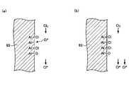
本実施の形態の一観点によれば、成膜方法は、基板の表面に窒化膜を成膜する成膜工程と、前記成膜工程の後に行うプラズマパージ工程と、を有し、前記成膜工程は、アルミニウムを含有する材料により形成されたガス吐出部を介して、前記基板の表面に、プラズマにより活性化された塩素ガスを供給して吸着させ、吸着阻害基を形成する工程と、前記基板の表面に、シリコン又は金属と塩素とを含有する原料ガスを供給し、前記吸着阻害基が形成されていない領域に前記原料ガスを吸着させる工程と、前記基板の表面に、窒化ガスを供給し、前記原料ガスとの反応により窒化膜を堆積させる工程と、を含み、前記プラズマパージ工程は、プラズマにより活性化された希ガスのみを、前記ガス吐出部に供給することで、前記ガス吐出部の表面に生じているAlClの結合からClを脱離させる。
According to one aspect of the present embodiment, a film formation method includes a film formation step of forming a nitride film on a surface of a substrate, and a plasma purge step performed after the film formation step, and The stepsinclude supplying plasma-activated chlorine gas to the surface of the substrate through a gas discharge part made of a material containing aluminum to adsorb the chlorine gas, thereby forming an adsorption-inhibiting group; a step of supplying a raw material gas containing silicon or metal and chlorine to the surface of a substrate to cause the raw material gas to be adsorbed on a region where the adsorption inhibiting group is not formed; and supplying a nitriding gas to the surface of the substrate. and depositing a nitride film by reacting with the raw material gas, wherein the plasma purge step suppliesonly the rare gas activated by the plasmato the gas discharge part, thereby performing the gas discharge. Cl is detached from AlCl bonds formed on the surface of the part .
開示の成膜方法によれば、窒化膜の成膜を繰り返した場合においても、再現性よく膜厚が略均一となる窒化膜を成膜することができる。 According to the disclosed film formation method, even when the film formation of the nitride film is repeated, it is possible to form a nitride film having a substantially uniform film thickness with good reproducibility.
本発明を実施するための形態について、以下に説明する。尚、同じ部材等については、同一の符号を付して説明を省略する。 Modes for carrying out the present invention will be described below. In addition, the same reference numerals are assigned to the same members and the description thereof is omitted.
(成膜装置)
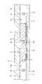
本実施の形態の成膜方法に用いられる成膜装置について説明する。本実施の形態の成膜方法に用いられる成膜装置は、図1から図3に示されるように、ほぼ円形の平面形状を有する扁平な真空容器1と、真空容器1内に設けられ、真空容器1の中心に回転中心を有する回転テーブル2と、を備えている。真空容器1は、内部に収容したウエハの表面上に成膜処理を行うための処理室である。真空容器1は、有底の円筒形状を有する容器本体12と、容器本体12の上面に対して、例えばOリングなどのシール部材13(図1)を介して気密に着脱可能に配置される天板11とを有している。(Deposition device)
A film forming apparatus used in the film forming method of this embodiment will be described. As shown in FIGS. 1 to 3, the film forming apparatus used in the film forming method of the present embodiment includes a flat vacuum vessel 1 having a substantially circular planar shape, and a vacuum chamber provided in the vacuum vessel 1. and a rotary table 2 having a center of rotation at the center of the container 1 . A vacuum vessel 1 is a processing chamber for performing a film forming process on the surface of a wafer accommodated therein. The vacuum container 1 includes a
回転テーブル2は、中心部にて円筒形状のコア部21に固定され、このコア部21は、鉛直方向に伸びる回転軸22の上端に固定されている。回転軸22は真空容器1の底部14を貫通し、下端が回転軸22(図1)を鉛直軸回りに回転させる駆動部23に取り付けられている。回転軸22及び駆動部23は、上面が開口した筒状のケース体20内に収納されている。ケース体20はその上面に設けられたフランジ部分が真空容器1の底部14の下面に気密に取り付けられており、ケース体20の内部雰囲気と外部雰囲気との気密状態が維持されている。 The rotary table 2 is fixed to a
回転テーブル2の表面部には、図2及び図3に示すように回転方向(周方向)に沿って複数(図示の例では5枚)の基板であるシリコン基板等の半導体ウエハ(以下「ウエハ」という)Wを載置するための円形状の凹部24が設けられている。尚、図3には便宜上1個の凹部24だけにウエハWを示す。この凹部24は、ウエハWの直径よりも僅かに例えば4mm大きい内径と、ウエハWの厚さにほぼ等しい深さとを有している。したがって、ウエハWが凹部24に収容されると、ウエハWの表面と回転テーブル2の表面(ウエハWが載置されない領域)とが同じ高さになる。凹部24の底面には、ウエハWの裏面を支えてウエハWを昇降させるための例えば3本の昇降ピンが貫通する貫通孔(いずれも図示せず)が形成されている。 As shown in FIGS. 2 and 3, on the surface of the rotary table 2, a plurality (five in the illustrated example) of semiconductor wafers such as silicon substrates (hereinafter referred to as "wafers") are arranged along the direction of rotation (circumferential direction). ) is provided with a
図2及び図3は、真空容器1内の構造を説明するための図であり、説明の便宜上、天板11の図示を省略している。図2及び図3に示すように、回転テーブル2の上方には、各々例えば石英からなる反応ガスノズル31、反応ガスノズル32、後述するリモートプラズマ発生器90のガス吐出部93d、及び分離ガスノズル41、42が真空容器1の周方向(回転テーブル2の回転方向(図3の矢印A))に互いに間隔をおいて配置されている。図示の例では、後述の搬送口15から時計回り(回転テーブル2の回転方向)に、リモートプラズマ発生器90のガス吐出部93d、分離ガスノズル41、反応ガスノズル31、分離ガスノズル42及び反応ガスノズル32がこの順番で配列されている。これらのノズル31、32、41、42は、各ノズル31、32、41、42の基端部であるガス導入ポート31a、32a、41a、42a(図3)を容器本体12の外周壁に固定することにより、真空容器1の外周壁から真空容器1内に導入され、容器本体12の半径方向に沿って回転テーブル2に対して水平に伸びるように取り付けられている。尚、後述するガス吐出部93dに接続されているリモートプラズマ発生器90のガス供給管92は、ガス導入ポート33aに接続されていてもよい。 2 and 3 are diagrams for explaining the structure inside the vacuum vessel 1, and the
本実施の形態においては、図3に示されるように、反応ガスノズル31は、配管110及び流量制御器120などを介して、原料ガスの供給源130に接続されている。反応ガスノズル32は、配管111及び流量制御器121などを介して、窒化ガスの供給源131に接続されている。更に、リモートプラズマ発生器90のガス供給管92は、配管112及び流量制御器122などを介して、塩素(Cl2)ガスの供給源132に接続されている。分離ガスノズル41、42は、いずれも不図示の配管及び流量制御バルブなどを介して、分離ガスの供給源(図示せず)に接続されている。分離ガスとしては、ヘリウム(He)やアルゴン(Ar)などの希ガスや窒素(N2)ガスなどの不活性ガスを用いることができる。本実施の形態では、Arガスを用いる例を挙げて説明する。In the present embodiment, as shown in FIG. 3, the
図4に示されるように、反応ガスノズル31、32には、回転テーブル2に向かって開口する複数の吐出孔35が、反応ガスノズル31、32の長さ方向に沿って、例えば10mmの間隔で配列されている。図2及び図3に示されるように、反応ガスノズル31の下方領域は、原料ガスをウエハWに吸着させるための第1の処理領域P1となる。反応ガスノズル32の下方領域は、第1の処理領域P1においてウエハWに吸着した原料ガスを窒化する窒化ガスを供給し、窒化膜を生成する第2の処理領域P2となる。リモートプラズマ発生器90のガス吐出部93dの下方領域は、第2の処理領域P2において生成した反応生成物(窒化膜)にプラズマにより活性化した塩素ガスを供給し、吸着阻害基を形成する第3の処理領域P3となる。本願においては、第1の処理領域P1は、原料ガスを供給する領域であるので、原料ガス供給領域P1と記載する場合がある。同様に、第2の処理領域P2は、原料ガスと反応して窒化物を生成可能な窒化ガスを供給する領域であるので、窒化ガス供給領域P2と記載する場合がある。また、第3の処理領域P3は、塩素ガスを供給する領域であるので、塩素ガス供給領域P3と記載する場合がある。 As shown in FIG. 4, in the
尚、第2の処理領域P2の上方には、プラズマ発生器80が設けられており、第3の処理領域P3の上方には、リモートプラズマ発生器90が設けられている。図3において、プラズマ発生器80及びリモートプラズマ発生器90は、破線で簡略化して示されている。プラズマ発生器80、リモートプラズマ発生器90の詳細については後述する。 A
尚、原料ガスとしては、シリコン及び塩素を含有するガス、又は金属及び塩素を含有するガスが選択される。例えば、窒化シリコン(SiN)膜を成膜する場合には、ジクロロシラン(DCS、SiH2Cl2)等のシリコン及び塩素を含有するガスが選択される。また、例えば、窒化チタン(TiN)膜、窒化アルミニウム(AlN)膜等の金属窒化膜を成膜する場合には、四塩化チタン(TiCl4)、三塩化アルミニウム(AlCl3)等の金属及び塩素を含有するガスが原料ガスとして選択される。As the material gas, a gas containing silicon and chlorine or a gas containing metal and chlorine is selected. For example, when forming a silicon nitride (SiN) film, a gas containing silicon and chlorine such as dichlorosilane (DCS, SiH2 Cl2 ) is selected. Further, for example, when forming a metal nitride film such as a titanium nitride (TiN) film or an aluminum nitride (AlN) film, a metal such as titanium tetrachloride (TiCl4 ) or aluminum trichloride (AlCl3 ) and chlorine are used. is selected as the source gas.
また、窒化ガスとしては、一般的にはアンモニア(NH3)含有ガスが選択される。その他、窒化ガスをプラズマにより活性化して供給する場合には、窒素(N2)含有ガスが選択される場合もある。尚、窒化ガスは、アンモニアの他、Ar等のキャリアガスを含んでもよい。Ammonia (NH3 )-containing gas is generally selected as the nitriding gas. In addition, nitrogen (N2 )-containing gas may be selected when nitriding gas is activated by plasma and supplied. The nitriding gas may contain a carrier gas such as Ar in addition to ammonia.
第3の反応ノズルから供給される塩素ガスは、第1の反応ガスノズル31から供給される原料ガスがウエハに吸着するのを阻害する吸着阻害基をウエハの表面上に形成する役割を有する。例えば、ウエハの表面にビア、トレンチ等の窪みパターンが形成されている場合には、ウエハの表面及び窪みパターンの上部に吸着阻害基を形成することにより、窪みパターンの上部では膜厚が厚くならず、底面側の膜厚が厚くなる。これにより、ボトムアップ性の高い成膜が可能となる。原料ガスが窒化されることにより、NH2構造の水素基で終端し、原料ガスに対して吸着サイトを形成しているが、活性化した塩素が供給されると、NH2構造のH基がCl基に置換されてしまう。上述のように、原料ガスが塩素を含有するガスであり、塩素同士は吸着しないため、塩素で終端化された箇所には原料ガスが吸着しない。このように、Cl基で終端された箇所は吸着阻害基として機能し、原料ガスの吸着を阻害する。尚、活性化した塩素ガスは、ウエハWの表面及び窪みパターンの上部には容易に到達するので多く吸着するが、窪みパターンの下部及び底部には到達し難くなるので、窪みパターンの底部に接近するにつれて、Cl基の密度は小さくなる。よって、窪みパターンの上部及びウエハの表面には高密度に吸着阻害基が形成されるが、窪みパターンの下部(底部)には、吸着阻害基が低密度で形成される。これにより、原料ガスがウエハWの表面及び上部により下部に多く吸着させることができ、窪みパターンの底部から成膜を開始するボトムアップ成膜が可能となる。尚、第3の反応ノズルから供給されるガスは、塩素ガスの他、Ar等のキャリアガスを含んでよい。The chlorine gas supplied from the third reaction nozzle has the role of forming adsorption inhibition groups on the surface of the wafer that inhibit the adsorption of the raw material gas supplied from the first
図2及び図3を参照すると、真空容器1内には2つの凸状部4が設けられている。凸状部4は、分離ガスノズル41、42とともに分離領域Dを構成するため、後述のとおり、回転テーブル2に向かって突出するように天板11の裏面に取り付けられている。また、凸状部4は、頂部が円弧状に切断された扇型の平面形状を有し、本実施の形態においては、内円弧が突出部5(後述)に連結し、外円弧が、真空容器1の容器本体12の内周面に沿うように配置されている。 2 and 3, two
図4は、反応ガスノズル31から反応ガスノズル32まで回転テーブル2の同心円に沿った真空容器1の断面を示している。図示のとおり、天板11の裏面に凸状部4が取り付けられているため、真空容器1内には、凸状部4の下面である平坦な低い天井面44(第1の天井面)と、この天井面44の周方向両側に位置する、天井面44よりも高い天井面45(第2の天井面)とが存在する。天井面44は、頂部が円弧状に切断された扇型の平面形状を有している。また、図示のとおり、凸状部4には周方向中央において、半径方向に伸びるように形成された溝部43が形成され、分離ガスノズル42が溝部43内に収容されている。もう一つの凸状部4にも同様に溝部43が形成され、ここに分離ガスノズル41が収容されている。また、高い天井面45の下方の空間に反応ガスノズル31、32がそれぞれ設けられている。これらの反応ガスノズル31、32は、天井面45から離間してウエハWの近傍に設けられている。尚、図4に示すように、高い天井面45の下方の右側の空間481に反応ガスノズル31が設けられ、高い天井面45の下方の左側の空間482に反応ガスノズル32が設けられる。 FIG. 4 shows a cross section of the vacuum vessel 1 along the concentric circles of the rotary table 2 from the
また、凸状部4の溝部43に収容される分離ガスノズル41、42には、回転テーブル2に向かって開口する複数のガス吐出孔42h(図4参照)が、分離ガスノズル41、42の長さ方向に沿って、例えば10mmの間隔で配列されている。 Further, the
天井面44は、狭隘な空間である分離空間Hを回転テーブル2に対して形成している。分離ガスノズル42の複数のガス吐出孔42hからArガスが供給されると、このArガスは、分離空間Hを通して空間481及び空間482へ向かって流れる。このとき、分離空間Hの容積は空間481及び482の容積よりも小さいため、Arガスにより分離空間Hの圧力を空間481及び482の圧力に比べて高くすることができる。すなわち、空間481及び482の間に圧力の高い分離空間Hが形成される。また、分離空間Hから空間481及び482へ流れ出るArガスが、第1の領域P1からの第1の反応ガスと、第2の領域P2からの第2の反応ガスとに対するカウンターフローとして働く。したがって、第1の領域P1からの第1の反応ガスと、第2の領域P2からの第2の反応ガスとが分離空間Hにより分離される。よって、真空容器1内において第1の反応ガスと第2の反応ガスとが混合し、反応することが抑制される。 The
尚、回転テーブル2の上面に対する天井面44の高さh1は、成膜時の真空容器1内の圧力、回転テーブル2の回転速度、供給する分離ガス(Arガス)の供給量などを考慮し、分離空間Hの圧力を空間481及び482の圧力に比べて高くするのに適した高さに設定することが好ましい。 The height h1 of the
一方、天板11の下面には、回転テーブル2を固定するコア部21の外周を囲む突出部5(図2及び図3)が設けられている。この突出部5は、本実施の形態においては、凸状部4における回転中心側の部位と連続しており、その下面が天井面44と同じ高さに形成されている。 On the other hand, the lower surface of the
先に参照した図1は、図3のI-I'線に沿った断面図であり、天井面45が設けられている領域を示している。一方、図5は、天井面44が設けられている領域を示す断面図である。図5に示すように、扇型の凸状部4の周縁部(真空容器1の外縁側の部位)には、回転テーブル2の外端面に対向するようにL字型に屈曲する屈曲部46が形成されている。この屈曲部46は、凸状部4と同様に、分離領域Dの両側から反応ガスが侵入することを抑制して、両反応ガスの混合を抑制する。扇型の凸状部4は天板11に設けられ、天板11が容器本体12から取り外せるようになっていることから、屈曲部46の外周面と容器本体12との間には僅かに隙間がある。屈曲部46の内周面と回転テーブル2の外端面との隙間、及び屈曲部46の外周面と容器本体12との隙間は、例えば回転テーブル2の上面に対する天井面44の高さと同様の寸法に設定されている。 FIG. 1 referred to above is a cross-sectional view taken along the line II' of FIG. 3 and shows the area where the
容器本体12の内周壁は、分離領域Dにおいては図4に示すように屈曲部46の外周面と接近して垂直面に形成されているが、分離領域D以外の部位においては、図1に示すように例えば回転テーブル2の外端面と対向する部位から底部14に亘って外方側に窪んでいる。以下、説明の便宜上、概ね矩形の断面形状を有する窪んだ部分を排気領域と記す。具体的には、第1の処理領域P1に連通する排気領域を第1の排気領域E1と記し、第2及び第3の処理領域P2、P3に連通する領域を第2の排気領域E2と記す。これらの第1の排気領域E1及び第2の排気領域E2の底部には、図1から図3に示すように、それぞれ、第1の排気口610及び第2の排気口620が形成されている。第1の排気口610及び第2の排気口620は、図1に示すように各々排気管630を介して真空排気手段である例えば真空ポンプ640に接続されている。また、真空ポンプ640と排気管630との間に、圧力制御器650が設けられる。尚、図1では、第1の排気口610について示すが、第2の排気口620についても同様である。 The inner peripheral wall of the
尚、図2及び図3に示されるように、第2の処理領域P2と第3の処理領域P3との間に分離領域Hは設けられていないが、図3において、プラズマ発生器80として示された領域に、回転テーブル2上の空間を仕切る筐体が設けられる。これにより、第2の処理領域P2と第3の処理領域P3との空間は仕切られる。 As shown in FIGS. 2 and 3, the isolation region H is not provided between the second processing region P2 and the third processing region P3, but in FIG. A housing that partitions the space on the rotary table 2 is provided in the area marked with the . This partitions the space between the second processing area P2 and the third processing area P3.
回転テーブル2と真空容器1の底部14との間の空間には、図1及び図5に示すように加熱手段であるヒータユニット7が設けられ、回転テーブル2を介して回転テーブル2上のウエハWが、プロセスレシピで決められた温度(例えば400℃)に加熱される。回転テーブル2の周縁付近の下方側には、回転テーブル2の上方空間から排気領域E1、E2に至るまでの雰囲気とヒータユニット7が置かれている雰囲気とを区画して回転テーブル2の下方領域へのガスの侵入を抑えるために、リング状のカバー部材71が設けられている(図5)。このカバー部材71は、回転テーブル2の外縁部及び外縁部よりも外周側を下方側から臨むように設けられた内側部材71aと、この内側部材71aと真空容器1の内壁面との間に設けられた外側部材71bと、を備えている。外側部材71bは、分離領域Dにおいて凸状部4の外縁部に形成された屈曲部46の下方にて、屈曲部46と近接して設けられ、内側部材71aは、回転テーブル2の外縁部下方(及び外縁部よりも僅かに外側の部分の下方)において、ヒータユニット7を全周に亘って取り囲んでいる。 As shown in FIGS. 1 and 5, a
ヒータユニット7が配置されている空間よりも回転中心寄りの部位における底部14は、回転テーブル2の下面の中心部付近におけるコア部21に接近するように上方側に突出して突出部12aをなしている。この突出部12aとコア部21との間は狭い空間になっており、また底部14を貫通する回転軸22の貫通穴の内周面と回転軸22との隙間が狭くなっていて、これら狭い空間はケース体20に連通している。そしてケース体20にはパージガスであるArガスを狭い空間内に供給してパージするためのパージガス供給管72が設けられている。また真空容器1の底部14には、ヒータユニット7の下方において周方向に所定の角度間隔で、ヒータユニット7の配置空間をパージするための複数のパージガス供給管73が設けられている(図5には一つのパージガス供給管73を示す)。また、ヒータユニット7と回転テーブル2との間には、ヒータユニット7が設けられた領域へのガスの侵入を抑えるために、外側部材71bの内周壁(内側部材71aの上面)から突出部12aの上端部との間を周方向に亘って覆う蓋部材7aが設けられている。蓋部材7aは例えば石英で作製することができる。 A
また、真空容器1の天板11の中心部には分離ガス供給管51が接続されていて、天板11とコア部21との間の空間52に分離ガスであるArガスを供給するように構成されている。この空間52に供給された分離ガスは、突出部5と回転テーブル2との狭い隙間となる空間50を介して回転テーブル2のウエハ載置領域側の表面に沿って周縁に向けて吐出される。空間50は分離ガスにより空間481及び空間482よりも高い圧力に維持され得る。したがって、空間50により、第1の処理領域P1に供給される原料ガスと第2の処理領域P2に供給される窒化ガスとが、中心領域Cを通って混合することが抑制される。すなわち、空間50(又は中心領域C)は分離空間H(又は分離領域D)と同様に機能することができる。 A separation
さらに、真空容器1の側壁には、図2、図3に示すように、外部の搬送アーム10と回転テーブル2との間で基板であるウエハWの受け渡しを行うための搬送口15が形成されている。この搬送口15は図示しないゲートバルブにより開閉される。また回転テーブル2におけるウエハ載置領域である凹部24はこの搬送口15に臨む位置にて搬送アーム10との間でウエハWの受け渡しが行われることから、回転テーブル2の下方側において受け渡し位置に対応する部位に、凹部24を貫通してウエハWを裏面から持ち上げるための受け渡し用の昇降ピン及びその昇降機構(いずれも図示せず)が設けられている。 Further, as shown in FIGS. 2 and 3, the side wall of the vacuum container 1 is formed with a
次に、図6から図8までを参照しながら、プラズマ発生器80について説明する。図6は、回転テーブル2の半径方向に沿ったプラズマ発生器80の概略断面図であり、図7は、回転テーブル2の半径方向と直交する方向に沿ったプラズマ発生器80の概略断面図であり、図8は、プラズマ発生器80の概略を示す上面図である。図示の便宜上、これらの図において一部の部材を簡略化している。 Next, the
図6を参照すると、プラズマ発生器80は、高周波透過性の材料で作製され、上面から窪んだ凹部を有し、天板11に形成された開口部11aに嵌め込まれるフレーム部材81と、フレーム部材81の凹部内に収容され、上部が開口した略箱状の形状を有するファラデー遮蔽板82と、ファラデー遮蔽板82の底面上に配置される絶縁板83と、絶縁板83の上方に支持され、略八角形の上面形状を有するコイル状のアンテナ85とを備える。 Referring to FIG. 6, the
天板11の開口部11aは複数の段部を有しており、そのうちの一つの段部には全周に亘って溝部が形成され、この溝部に例えばO-リングなどのシール部材81aが嵌め込まれている。一方、フレーム部材81は、開口部11aの段部に対応する複数の段部を有しており、フレーム部材81を開口部11aに嵌め込むと、複数の段部のうちの一つの段部の裏面が、開口部11aの溝部に嵌め込まれたシール部材81aと接する。これにより、天板11とフレーム部材81との間の気密性が維持される。また、図6に示すように、天板11の開口部11aに嵌め込まれるフレーム部材81の外周に沿った押圧部材81cが設けられ、これにより、フレーム部材81が天板11に対して下方に押し付けられる。このため、天板11とフレーム部材81との間の気密性がより確実に維持される。 The
フレーム部材81の下面は、真空容器1内の回転テーブル2に対向しており、その下面の外周には全周に亘って下方に(回転テーブル2に向かって)突起する突起部81bが設けられている。突起部81bの下面は回転テーブル2の表面に近接しており、突起部81bと、回転テーブル2の表面と、フレーム部材81の下面とにより回転テーブル2の上方に空間(第2の処理領域P2)が画成されている。尚、突起部81bの下面と回転テーブル2の表面との間隔は、分離空間H(図4)における天井面44の回転テーブル2の上面に対する高さh1とほぼ同じであって良い。 The lower surface of the
また、この第2の処理領域P2には、突起部81bを貫通した反応ガスノズル32が延びている。反応ガスノズル32には、本実施の形態においては、図6に示すように、窒化ガスが充填される窒化ガスの供給源131が、流量制御器121を介して配管111により接続されている。流量制御器121により流量制御された窒化ガスが、プラズマ発生器80で活性化され、所定の流量で第2の処理領域P2に供給される。 In addition, the
また、反応ガスノズル32には、その長手方向に沿って所定の間隔(例えば10mm)で複数の吐出孔35が形成されており、吐出孔35から上述の窒化ガスが吐出される。吐出孔35は、図7に示すように、回転テーブル2に対して垂直な方向から回転テーブル2の回転方向の上流側に向かって傾いている。このため、反応ガスノズル32から供給されるガスは、回転テーブル2の回転方向と逆の方向に、具体的には、突起部81bの下面と回転テーブル2の表面との間の隙間に向かって吐出される。これにより、回転テーブル2の回転方向に沿ってプラズマ発生器80よりも上流側に位置する天井面45の下方の空間から反応ガスや分離ガスが、第2の処理領域P2内へ流れ込むのが抑止される。また、上述のとおり、フレーム部材81の下面の外周に沿って形成される突起部81bが回転テーブル2の表面に近接しているため、反応ガスノズル32からのガスにより第2の処理領域P2内の圧力を容易に高く維持することができる。これによっても、反応ガスや分離ガスが第2の処理領域P2内へ流れ込むのが抑止される。 A plurality of discharge holes 35 are formed in the
このように、フレーム部材81は、第2の処理領域P2を第3の処理領域P3から分離するための役割を担っている。よって、本実施の形態の成膜方法に用いられる成膜装置は、プラズマ発生器80の全体を必ずしも備えていなくて良いが、第2の処理領域P2を第3の処理領域P3から区画し、反応ガスの混入を防ぐため、フレーム部材81を備えているものとする。 Thus, the
ファラデー遮蔽板82は、金属などの導電性材料から作製され、図示は省略するが接地されている。図8に明確に示されるように、ファラデー遮蔽板82の底部には、複数のスリット82sが形成されている。各スリット82sは、略八角形の平面形状を有するアンテナ85の対応する辺とほぼ直交するように延びている。 The
また、ファラデー遮蔽板82は、図7及び図8に示すように、上端の2箇所において外側に折れ曲がる支持部82aを有している。支持部82aがフレーム部材81の上面に支持されることにより、フレーム部材81内の所定の位置にファラデー遮蔽板82が支持される。 As shown in FIGS. 7 and 8, the
絶縁板83は、例えば石英ガラスにより作製され、ファラデー遮蔽板82の底面よりも僅かに小さい大きさを有し、ファラデー遮蔽板82の底面に載置される。絶縁板83は、ファラデー遮蔽板82とアンテナ85とを絶縁する一方、アンテナ85から放射される高周波を下方へ透過させる。 The insulating
アンテナ85は、平面形状が略八角形となるように銅製の中空管(パイプ)を例えば3重に巻き回すことにより形成される。パイプ内に冷却水を循環させることができ、これにより、アンテナ85へ供給される高周波によりアンテナ85が高温に加熱されるのが防止される。また、アンテナ85には立設部85aが設けられており、立設部85aに支持部85bが取り付けられている。支持部85bにより、アンテナ85がファラデー遮蔽板82内の所定の位置に維持される。また、支持部85bには、マッチングボックス86を介して高周波電源87が接続されている。高周波電源87は、例えば13.56MHzの周波数を有する高周波を発生することができる。 The
このような構成を有するプラズマ発生器80によれば、マッチングボックス86を介して高周波電源87からアンテナ85に高周波電力を供給すると、アンテナ85により電磁界が発生する。この電磁界のうちの電界成分は、ファラデー遮蔽板82により遮蔽されるため、下方へ伝播することはできない。一方、磁界成分はファラデー遮蔽板82の複数のスリット82sを通して第2の処理領域P2内へ伝播する。この磁界成分により、反応ガスノズル32から所定の流量比で第2の処理領域P2に供給される窒化ガスが活性化される。 According to the
ところで、塩素ガスは、あまり強くプラズマ化すると、下地膜UFをエッチングしてしまう場合がある。図6乃至8で説明したアンテナ85を用いたプラズマ発生器80は、誘導型プラズマ発生器(ICP、Inductively Coupled Plasma)であり、高いプラズマ強度でプラズマを発生させるのに有効である。しかしながら、塩素の活性化は、もっと弱いプラズマを発生させるプラズマ発生器を用いる方が好ましい。即ち、塩素ガスの供給は、塩素ガスをウエハWの窪みパターンの上部に高密度で吸着させ、窪みパターンの上部に吸着阻害基を発生することを意図しており、膜のエッチングを意図していない。よって、塩素ガスのプラズマ化は、あまりプラズマ強度を高めずに、エッチング作用を発生させない範囲で行う。このようにして発生するプラズマによれば、ウエハWの表面に形成されたビア、トレンチ等の窪みパターンの上部に吸着して原料ガスに対する吸着阻害基を形成し、吸着阻害基により原料ガスの吸着が妨げられない底部側からの成膜を行うことができる。リモートプラズマ発生器90は、プラズマ発生器80よりも弱いプラズマを発生させるのに適している。よって、本実施の形態における成膜装置では、第3の処理領域P3における塩素ガスの活性化をリモートプラズマ発生器90を用いて行う。 By the way, chlorine gas may etch the underlying film UF if it is turned into plasma too strongly. The
図9は、本実施の形態における成膜装置のリモートプラズマ発生器90を含む部分の断面図である。 FIG. 9 is a cross-sectional view of a portion including the
図3等に示されるように、リモートプラズマ発生器90は、第3の処理領域P3に設けられており、図9に示されるように、回転テーブル2と対向している。リモートプラズマ発生器90は、プラズマ生成部91と、ガス供給管92と、シャワーヘッド部93と、配管94とを備えている。尚、シャワーヘッド部93は、塩素ガス吐出部の一例であり、例えば、シャワーヘッド部93の代わりに、ガスノズルが用いられてもよい。 As shown in FIG. 3 and the like, the
プラズマ生成部91は、ガス供給管92から供給された塩素ガスをプラズマ源により活性化する。プラズマ源としては、塩素ガスを活性化することが可能であれば、特に限定されるものではない。プラズマ源としては、例えば誘導結合型プラズマ(ICP:Inductively Coupled Plasma)、容量結合型プラズマ(CCP:Capacitively Coupled Plasma)、表面波プラズマ(SWP:Surface Wave Plasma)を用いることができる。 The
ガス供給管92は、その一端がプラズマ生成部91と接続されており、プラズマ生成部91に塩素ガスを供給する。ガス供給管92の他端は、例えば開閉バルブ及び流量調整器を介して塩素ガスが貯留された塩素ガス供給源132と接続されている。 One end of the
シャワーヘッド部93は、配管94を介してプラズマ生成部91と接続されており、プラズマ生成部91で活性化されたフッ素含有ガスを真空容器1内に供給する部分である。シャワーヘッド部93は、扇型の平面形状を有し、扇型の平面形状の外縁に沿うように形成された押圧部材95によって下方側に向かって周方向に亘って押圧される。また、押圧部材95が図示しないボルト等により天板11に固定されることにより、真空容器1の内部雰囲気が気密状態とされる。天板11に固定されたときのシャワーヘッド部93の下面と回転テーブル2の上面との間隔は、例えば0.5mmから5mm程度とすることができる。 The
シャワーヘッド部93には、回転テーブル2の角速度の違いに対応して回転中心側で少なく、外周側で多くなるように複数のガス吐出孔93aが設けられている。複数のガス吐出孔93aの個数としては、例えば数十~数百個とすることができる。また、複数のガス吐出孔93aの直径としては、例えば0.5mmから3mm程度とすることができる。シャワーヘッド部93に供給された活性化された塩素ガスは、ガス吐出孔93aを通って回転テーブル2とシャワーヘッド部93との間の空間に供給される。 The
図10は、シャワーヘッド部93の下面の一例を示した平面図である。図10に示されるように、下方突出面93cは、扇形のシャワーヘッド部93の下面93bの外周に沿うように、帯状に設けられてもよい。これにより、周方向に均一に第3の処理領域P3の外周側の圧力の低下を防止することができる。また、ガス吐出孔93aは、シャワーヘッド部93の下面93bの周方向の中央に、半径方向に延在するように設けられてもよい。これにより、回転テーブル2の中心側から外周側に分散させて塩素ガスを供給することができる。本願においては、シャワーヘッド部93において複数のガス吐出孔93aが設けられている部分をガス吐出部93dと記載する場合がある。 FIG. 10 is a plan view showing an example of the lower surface of the
このように、リモートプラズマ発生器90を用いて、活性化した塩素ガスをウエハWに供給している。 Thus, activated chlorine gas is supplied to the wafer W using the
また、本実施の形態の成膜方法に用いられる成膜装置には、図1に示すように、装置全体の動作のコントロールを行うためのコンピュータからなる制御部100が設けられており、この制御部100のメモリ内には、制御部100の制御の下に、後述する成膜方法を成膜装置に実施させるプログラムが格納されている。このプログラムは後述の成膜方法を実行するようにステップ群が組まれており、ハードディスク、コンパクトディスク、光磁気ディスク、メモリカード、フレキシブルディスクなどの媒体102に記憶されており、所定の読み取り装置により記憶部101へ読み込まれ、制御部100内にインストールされる。 Further, as shown in FIG. 1, the film forming apparatus used in the film forming method of the present embodiment is provided with a
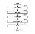
(成膜方法の一例)
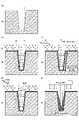
次に、上述した成膜装置を用いたSiN膜の成膜方法の一例を図11及び図12に基づき説明する。尚、図11は、このSiN膜の成膜方法の一例の工程を説明するフローチャートであり、図12は、成膜工程におけるウエハWの断面の様子を模式的に示す。このSiN膜の成膜方法の説明では、ウエハWとしてシリコンウエハを用いるものとし、シリコンウエハの表面には、図12(a)に示すように、トレンチTが形成されている。(Example of film formation method)
Next, an example of a method for forming a SiN film using the film forming apparatus described above will be described with reference to FIGS. 11 and 12. FIG. FIG. 11 is a flow chart for explaining the steps of one example of the SiN film forming method, and FIG. 12 schematically shows the state of the cross section of the wafer W in the film forming step. In the description of the SiN film forming method, a silicon wafer is used as the wafer W, and trenches T are formed in the surface of the silicon wafer, as shown in FIG. 12(a).
尚、上述した成膜装置を用いてSiN膜を成膜する場合について説明する。この場合には、反応ガスノズル31からジクロロシラン(DCS、SiH2Cl2)が供給され、反応ガスノズル32から窒化ガスとしてアンモニア(NH3)が供給され、リモートプラズマ発生器90のガス吐出部93dから活性化された塩素が供給される。また、プラズマ発生器80も搭載されており、塩素ガス及びアンモニアガスは、活性化されることによりイオン化又はラジカル化して供給される。A case of forming a SiN film using the film forming apparatus described above will be described. In this case, dichlorosilane (DCS, SiH2 Cl2 ) is supplied from the
最初に、ステップ102(S102)に示されるように、上述した成膜装置の真空容器1内の回転テーブル2の5つの凹部24内に夫々ウエハWを載置する。具体的には、上述した成膜装置の不図示のゲートバルブを開き、外部から搬送アーム10(図3)により搬送口15(図2及び図3)を介してウエハWを回転テーブル2の凹部24内に受け渡す。この受け渡しは、凹部24が搬送口15に臨む位置に停止したときに凹部24の底面の貫通孔を介して真空容器1の底部側から不図示の昇降ピンが昇降することにより行われる。このようなウエハWの受け渡しを、回転テーブル2を間欠的に回転させて行い、回転テーブル2の5つの凹部24内に夫々ウエハWを載置する。 First, as shown in step 102 (S102), the wafers W are respectively placed in the five
次に、ステップ104(S104)に示されるように、上述した成膜装置の真空容器1内を排気する。具体的には、上述した成膜装置のゲートバルブを閉じ、真空ポンプ640により到達可能真空度にまで真空容器1内を排気する。 Next, as shown in step 104 (S104), the inside of the vacuum vessel 1 of the film forming apparatus described above is evacuated. Specifically, the gate valve of the film forming apparatus described above is closed, and the inside of the vacuum vessel 1 is evacuated to a reachable degree of vacuum by the
次に、ステップ106(S106)に示されるように、ウエハWのトレンチTが形成されている面にSiNにより下地膜UFを成膜する。具体的には、分離ガスノズル41、42から分離ガスであるArガスを所定の流量で吐出し、分離ガス供給管51及びパージガス供給管72、73からもArガスを所定の流量で吐出する。この後、反応ガスノズル31(図2及び図3)からDCSを供給し、反応ガスノズル32からアンモニアガスを供給する。また、プラズマ発生器80も作動させる。アンモニアガスは、プラズマ発生器80により活性化される。これに伴い、圧力制御器650(図1)により真空容器1内を予め設定した処理圧力に制御する。次いで、回転テーブル2を時計回りに例えば5rpmの回転速度で回転させながらヒータユニット7によりウエハWを例えば400℃に加熱する。回転テーブル2の回転速度は、用途に応じて種々の回転速度に設定することができる。このように、反応ガスノズル31から供給されたDCSと、反応ガスノズル32から供給されたアンモニアガスとが反応し、SiNの下地膜UFが成膜される。 Next, as shown in step 106 (S106), a base film UF is formed of SiN on the surface of the wafer W on which the trenches T are formed. Specifically, Ar gas, which is the separation gas, is discharged from the
回転テーブル2の回転により、ウエハWは、第3の処理領域P3、分離領域D、第1の処理領域P1、分離領域D、第2の処理領域P2をこの順に繰り返して通過する(図3参照)。これにより、図12(b)に示されるように、ウエハWのトレンチTの底面及び側面を含むトレンチTの形成されている面に下地膜UFが成膜される。このように成膜される下地膜UFは、ボトムアップ性の高い膜ではなく、トレンチTの形状に沿ったコンフォーマルな膜である。尚、図12(b)に示す状態は、第2の処理領域P2を通過した直後の状態を示しており、SiNにより形成される下地膜UFの最表面は、NH2構造を有するH基で終端されている。これは、第2の処理領域P2を通過した際に、NH3含有ガスで窒化されているからである。また、本願においては、分離領域Dをパージガス供給領域と記載する場合がある。As the
次に、ステップ108(S108)に示されるように、ウエハWのトレンチT内をSiNにより埋め込む埋め込み膜を成膜する。具体的には、リモートプラズマ発生器90に塩素ガスを供給し、リモートプラズマ発生器90を作動させることにより、リモートプラズマ発生器90のガス吐出部93dから活性化された塩素を供給する。尚、回転テーブル2の回転により、各領域P1~P3、Dから処理が開始されるウエハWが各々存在するが、便宜上、第3の処理領域P3からウエハWが通過する状態より説明する。 Next, as shown in step 108 (S108), a buried film is formed to fill the trenches T of the wafer W with SiN. Specifically, by supplying chlorine gas to the
図12(c)は、吸着阻害基形成工程の一例を示した図である。吸着阻害基形成工程では、第3の処理領域P3をウエハWが通過することにより、トレンチT内の下地膜UF上に、プラズマにより活性化された塩素ガス(塩素ラジカル、塩素イオン)が供給される。これにより、図12(c)に示されるように、塩素ガスは、H基と反応してHClを生成するとともに、H基と置換してCl基終端を形成する。かかるCl基は、塩素含有ガスに対しては、吸着阻害基を形成する。ここで、塩素ガスは、ウエハWの表面S、トレンチTの上部には容易に到達するが、トレンチTの奥、つまり底部付近の下部にはあまり多くは到達しない。トレンチTのアスペクト比は高いので、多くの塩素ガスは、トレンチTの奥に到達する前にH基と置換してしまう。よって、ウエハWの表面S及びトレンチTの上部には高密度で吸着阻害基であるCl基が形成されるが、トレンチTの下部にはNH2構造のH基が多く残存し、Cl基の密度は低くなる。FIG. 12(c) is a diagram showing an example of the adsorption-inhibiting group forming step. In the adsorption inhibiting group forming step, chlorine gas (chlorine radicals, chlorine ions) activated by plasma is supplied onto the underlying film UF in the trenches T by passing the wafer W through the third processing region P3. be. As a result, as shown in FIG. 12(c), the chlorine gas reacts with the H groups to generate HCl and replaces the H groups to form Cl group terminations. Such Cl groups form adsorption-inhibiting groups for chlorine-containing gases. Here, the chlorine gas easily reaches the surface S of the wafer W and the upper portion of the trench T, but not so much reaches the inner part of the trench T, that is, the lower portion near the bottom. Since the trench T has a high aspect ratio, a large amount of chlorine gas replaces H groups before reaching the depth of the trench T. Therefore, Cl groups, which are adsorption-inhibiting groups, are formed at a high density on the surface S of the wafer W and the upper portions of the trenches T, but a large amount of H groups of the NH2 structure remain in the lower portions of the trenches T, and Cl groups are formed. Density is low.
図12(d)は、原料ガス吸着工程の一例を示した図である。原料ガス吸着工程では、ウエハWが分離領域Dを通過してパージガスが供給されてパージされた後、第1の処理領域P1を通過することにより、DCSが供給される。これにより、図12(d)に示されるように、DCSは、吸着阻害基であるCl基が存在する領域にはあまり吸着せず、吸着阻害基の存在しない領域に多く吸着する。よって、トレンチT内の底面付近にDCSが多く吸着し、ウエハWの表面S及びトレンチTの上部にはあまりDCSが吸着しない。つまり、トレンチTの底部付近に原料ガスであるDCSが高密度で吸着し、トレンチTの上部及びウエハWの表面上にはDCSが低密度で吸着する。 FIG. 12(d) is a diagram showing an example of the source gas adsorption step. In the source gas adsorption step, the wafer W passes through the separation region D, is purged with the purge gas, and then passes through the first processing region P1 to supply the DCS. As a result, as shown in FIG. 12(d), DCS does not adsorb so much in the region where Cl groups, which are adsorption-inhibiting groups, are present, but adsorbs more in regions where adsorption-inhibiting groups do not exist. Therefore, a large amount of DCS is adsorbed near the bottom surface of the trench T, and less DCS is adsorbed on the surface S of the wafer W and the upper portion of the trench T. FIG. In other words, DCS, which is the raw material gas, is adsorbed near the bottom of the trench T at a high density, and DCS is adsorbed at a low density on the upper part of the trench T and the surface of the wafer W. FIG.
図12(e)は、窒化膜堆積工程の一例を示した図である。窒化膜堆積工程では、ウエハWが分離領域Dを通過してパージガスが供給されてパージされた後、第2の処理領域P2を通過することにより、プラズマにより活性化されたNH3ガスが供給される。これにより、図12(e)に示されるように、NH3ガスの供給により、トレンチT内に吸着したDCSと供給されたNH3とが反応し、窒化膜であるSiN膜が反応生成物として形成される。ここで、DCSは、トレンチTの底部付近に多く吸着しているので、トレンチT内の底部付近に多くSiN膜が形成される。よって、図12(e)に示されるようなボトムアップ性の高い埋め込み成膜が可能となる。FIG. 12E is a diagram showing an example of the nitride film deposition process. In the nitride film deposition process, the wafer W passes through the isolation region D and is purged by being supplied with a purge gas, and then passes through the second processing region P2 to be supplied with NH3 gas activated by plasma. be. As a result, as shown in FIG. 12(e), due to the supply ofNH3 gas, the DCS adsorbed in the trench T reacts with the suppliedNH3 , and the SiN film, which is a nitride film, is produced as a reaction product. It is formed. Here, since DCS is mostly adsorbed near the bottom of the trench T, a large amount of SiN film is formed near the bottom of the trench T. As shown in FIG. Therefore, it is possible to form an embedded film with a high bottom-up property as shown in FIG. 12(e).
更に、ウエハWが第3の処理領域P3を通過すると、再び図12(c)に示した状態となり、吸着阻害基であるCl基がトレンチT内の上部及びウエハWの表面に吸着する。 Furthermore, when the wafer W passes through the third processing region P3, the state shown in FIG.
以下、各反応ガスを供給しながら回転テーブル2を繰り返し回転させることにより、図12(c)~図12(e)に示したサイクルが繰り替えされ、トレンチTの開口部が塞がれない状態で、底面側からSiN膜が堆積する。そして、図12(e)に示されるように、V字の断面を形成しつつ、開口部を塞がないボトムアップ性に高いSiN膜の成膜を行うことができる。そして、最終的には、シームレスな窒化膜でトレンチTを埋め込むことができ、ボイド等を発生させることなく高品質な窒化膜の埋め込み成膜を行うことができる。 Thereafter, by repeatedly rotating the
次に、ステップ110(S110)に示されるように、パージを行う。具体的には、反応ガスノズル31からのDCSの供給を停止し、リモートプラズマ発生器90への塩素の供給及びリモートプラズマ発生器90を停止することにより、ガス吐出部93dからの活性化された塩素の供給を停止する。更に、プラズマ発生器80を停止する。従って、分離ガスノズル41、42から分離ガスであるArガスを所定の流量で吐出し、分離ガス供給管51及びパージガス供給管72、73からもArガスを所定の流量で吐出し、反応ガスノズル32からアンモニアガスを供給した状態を10分間続ける。尚、リモートプラズマ発生器90にArガスは供給されてはいるが、リモートプラズマ発生器90は動作していないため、供給されているArは活性化されてはいない。 Next, purging is performed as shown in step 110 (S110). Specifically, by stopping the supply of DCS from the
この後、上述した成膜装置の真空容器1内をリークすることにより大気圧に戻し、真空容器1内より、SiNの埋め込み膜が成膜されたウエハWを取り出す。 After that, the inside of the vacuum vessel 1 of the above-described film forming apparatus is leaked to return to the atmospheric pressure, and the wafer W with the SiN filling film formed thereon is taken out from the inside of the vacuum vessel 1 .
このような成膜方法によれば、活性化された塩素ガスをトレンチTの上部に供給して吸着阻害基を形成しつつALD(Atomic Layer Deposition)法による成膜を行うことにより、ボトムアップ性の高い選択的な成膜を行うことができる。 According to such a film forming method, the activated chlorine gas is supplied to the upper part of the trench T to form the adsorption inhibiting group, and the film is formed by the ALD (Atomic Layer Deposition) method. A highly selective film formation can be performed.
尚、NH3は、必ずしもプラズマにより活性化されて供給される必要はなく、窒化が可能であれば、プラズマ化されずに供給してもよい。NH3 does not necessarily need to be activated by plasma and supplied, and may be supplied without plasma if nitridation is possible.
このような成膜方法によれば、トレンチTの底面からSiN膜を埋め込むことができ、ボイドを発生させない高品質の埋め込み成膜を行うことができる。 According to such a film formation method, the SiN film can be embedded from the bottom surface of the trench T, and high-quality embedded film formation can be performed without generating voids.
ところで、上記の成膜方法によりSiN膜を成膜した場合、発明者らは、成膜を繰り返すと経時的にSiN膜の膜厚が薄くなる、即ち、SiN膜の成膜レートが低下することを見出した。具体的には、図13に示すように、同じ成膜時間で、1回目の成膜、2回目の成膜、3回目の成膜、4回目の成膜、5回目の成膜を順に経時的に行った場合、成膜されるSiN膜の膜厚が徐々に低下することを見出した。尚、図13に示す場合では、SiNの膜厚は、1回目の成膜では約180Å、2回目の成膜では約177Å、3回目の成膜では約175Å、4回目の成膜では約173.5Å、5回目の成膜では約172Åであり、バラツキは±2.3%であった。 By the way, when the SiN film is formed by the above film forming method, the inventors found that the film thickness of the SiN film decreases with time as the film forming method is repeated, that is, the film forming rate of the SiN film decreases. I found Specifically, as shown in FIG. 13, the first film formation, the second film formation, the third film formation, the fourth film formation, and the fifth film formation are sequentially performed with the same film formation time. It has been found that the film thickness of the SiN film to be formed gradually decreases when the method is carried out systematically. In the case shown in FIG. 13, the film thickness of SiN is about 180 Å in the first film formation, about 177 Å in the second film formation, about 175 Å in the third film formation, and about 173 Å in the fourth film formation. 0.5 Å, and about 172 Å in the fifth film formation, with a variation of ±2.3%.
このように、成膜を続けた場合、徐々にSiN膜の成膜レートが低下すると、ウエハWに形成されたトレンチTの埋め込みが良好ではなくなり、歩留まり等の低下を招くため好ましくない。このため、成膜を続けても、SiN膜の成膜レートが低下することなく、再現性よくSiN膜を安定的に成膜することのできる成膜方法が求められている。 When the film formation is continued in this way, if the film formation rate of the SiN film is gradually lowered, the embedding of the trenches T formed in the wafer W will not be satisfactory, resulting in a decrease in yield and the like, which is not preferable. Therefore, there is a demand for a film formation method that can stably form a SiN film with good reproducibility without lowering the film formation rate of the SiN film even if film formation is continued.
(成膜レートの低下の原因)
発明者らは、上記のような成膜方法においては、経時的に成膜レートが低下することについて検討を行った。この結果、リモートプラズマ発生器90のシャワーヘッド部93等の表面に塩素が付着し、このように付着した塩素は、上記のパージ工程においては、取り除くことができないことに起因していることに想到した。(Cause of decrease in deposition rate)
The inventors have investigated the decrease in film formation rate over time in the film formation method described above. As a result, chlorine adheres to the surface of the
具体的には、リモートプラズマ発生器90のシャワーヘッド部93等はアルミニウム(Al)により形成されており、SiN膜を成膜する際には、リモートプラズマ発生器90のシャワーヘッド部93には塩素ガスが供給される。供給された塩素ガスはリモートプラズマ発生器90により活性化されるため、図14(a)に示されるように、シャワーヘッド部93等の表面のAlと結合し表面にAlClの結合が形成される。このように、シャワーヘッド部93等の表面にAlClの結合が形成されると、SiN膜を成膜する際に、図14(b)に示されるように、活性化したClが、シャワーヘッド部93等の表面に付着する量が徐々に減少する。このため、第3の処理領域P3に供給される活性化されたClが徐々に多くなる。第3の処理領域P3に供給される活性化されたClが増えると、活性化されたClは吸着阻害ガスとして作用するため、成膜されるSiN膜の成膜レートが徐々に遅くなる。このようなメカニズムにより、SiN膜の膜厚が成膜するたびに徐々に薄くなるものと推察される。尚、リモートプラズマ発生器90のシャワーヘッド部93等はアルマイト処理がなされている場合があるが、この場合には、シャワーヘッド部93等の表面のAlと結合しているOと活性化されたClとが置換し、AlClの結合が形成されるものと考えられる。 Specifically, the
ここで、発明者らは検討を行い、パージ工程においてプラズマを発生させることに想到した。具体的には、パージ工程においては、塩素ガスは供給されることなくArガスが供給されているが、このようにArガスが供給されている状態において、リモートプラズマ発生器90によりプラズマを発生させる。このようにパージ工程においてプラズマを発生させることにより、図15(a)に示されるように、Arが活性化され、活性化されたArにより、シャワーヘッド部93等の表面のAlと結合しているClが脱離する。本願においては、この工程をプラズマパージ工程と記載する。 Here, the inventors conducted studies and came up with the idea of generating plasma in the purge process. Specifically, in the purge step, Ar gas is supplied without supplying chlorine gas. In this state in which Ar gas is supplied, plasma is generated by the
このように、シャワーヘッド部93等の表面のAlと結合しているClを脱離させることにより、この後、図15(b)に示されるように、SiNの成膜の際に活性化されたClが、シャワーヘッド部93等の表面のAlと結合する。これにより、第3の処理領域P3に供給される活性化されたClが増加することはなく、一定で安定的となり、SiN膜の膜厚が成膜するたびに徐々に薄くなることを防ぐことができ、膜厚再現性の高いSiN膜を成膜することができる。 In this way, by desorbing Cl that is bound to Al on the surface of the
尚、上述した図11に示される成膜方法のステップ110のパージ工程においても、Arガスは供給されているが、プラズマは発生していないため、Arは活性化されてはいない。このため、図16に示すように、シャワーヘッド部93等の表面のAlと結合しているClを脱離させることはできず、図11に示される成膜方法では、SiN膜の膜厚が成膜するたびに徐々に薄くなってしまう。 Although Ar gas is supplied in the purge step of
(本実施の形態における成膜方法)
次に、本実施の形態における成膜方法について説明する。本実施の形態における成膜方法は、上述した成膜装置を用いたSiN膜の成膜方法であり、図17に基づき説明する。尚、図17は、実施の形態における成膜方法によりSiN膜を成膜する工程を説明するフローチャートである。(Deposition method in the present embodiment)
Next, a film forming method according to this embodiment will be described. The film forming method according to the present embodiment is a method for forming a SiN film using the film forming apparatus described above, and will be described with reference to FIG. FIG. 17 is a flow chart for explaining the steps of forming a SiN film by the film forming method according to the embodiment.
最初に、ステップ102(S102)に示されるように、上述した成膜装置の真空容器1内の回転テーブル2の5つの凹部24内に夫々ウエハWを載置する。 First, as shown in step 102 (S102), the wafers W are respectively placed in the five
次に、ステップ104(S104)に示されるように、上述した成膜装置の真空容器1内を排気する。 Next, as shown in step 104 (S104), the inside of the vacuum vessel 1 of the film forming apparatus described above is evacuated.
次に、ステップ106(S106)に示されるように、ウエハWのトレンチTが形成されている面にSiNにより下地膜UFを成膜する。 Next, as shown in step 106 (S106), a base film UF is formed of SiN on the surface of the wafer W on which the trenches T are formed.
次に、ステップ108(S108)に示されるように、ウエハWのトレンチT内をSiNにより埋め込む埋め込み膜を成膜する。具体的には、リモートプラズマ発生器90に塩素ガスを供給し、リモートプラズマ発生器90を作動させることにより、リモートプラズマ発生器90のガス吐出部93dから活性化された塩素を供給する。 Next, as shown in step 108 (S108), a buried film is formed to fill the trenches T of the wafer W with SiN. Specifically, by supplying chlorine gas to the
次に、ステップ120(S120)に示されるように、プラズマパージを行う。具体的には、反応ガスノズル31からのDCSの供給を停止し、リモートプラズマ発生器90への塩素の供給を停止するとともに、プラズマ発生器80を停止する。従って、分離ガスノズル41、42から分離ガスであるArガスを所定の流量で吐出し、分離ガス供給管51及びパージガス供給管72、73からもArガスを所定の流量で吐出し、反応ガスノズル32からアンモニアガスを供給した状態を10分間続ける。この状態においては、リモートプラズマ発生器90は動作しており、リモートプラズマ発生器90に供給されているArが活性化される。 Next, as shown in step 120 (S120), plasma purge is performed. Specifically, the supply of DCS from the
この後、上述した成膜装置の真空容器1内をリークすることにより大気圧に戻し、真空容器1内より、SiNの埋め込み膜が成膜されたウエハWを取り出す。 After that, the inside of the vacuum vessel 1 of the above-described film forming apparatus is leaked to return to the atmospheric pressure, and the wafer W with the SiN filling film formed thereon is taken out from the inside of the vacuum vessel 1 .
尚、NH3は、必ずしもプラズマにより活性化されて供給される必要はなく、窒化が可能であれば、プラズマ化されずに供給してもよい。NH3 does not necessarily need to be activated by plasma and supplied, and may be supplied without plasma if nitridation is possible.
本実施の形態における成膜方法により成膜されたSiN膜について説明する。具体的には、本実施の形態における成膜方法により同じ成膜時間で1回目の成膜、2回目の成膜、3回目の成膜、4回目の成膜、5回目の成膜を順に経時的に行った。この結果、図18に示されるように、SiNの膜厚は、1回目の成膜では約186Å、2回目の成膜では約184.5Å、3回目の成膜では約184Å、4回目の成膜では約182Å、5回目の成膜では約181.5Åであり、バラツキは±1.2%であった。 A SiN film formed by the film forming method according to the present embodiment will be described. Specifically, the first film formation, the second film formation, the third film formation, the fourth film formation, and the fifth film formation are performed in the same film formation time by the film formation method in this embodiment. Went over time. As a result, as shown in FIG. 18, the SiN film thickness was about 186 Å for the first film formation, about 184.5 Å for the second film formation, about 184 Å for the third film formation, and about 184 Å for the fourth film formation. The thickness of the film was about 182 Å, and the thickness of the fifth film was about 181.5 Å, with a variation of ±1.2%.
従って、図13に示す場合と比較して、SiN膜の膜厚のバラツキを約半分にすることができる。よって、本実施の形態における成膜方法は、SiN膜の成膜を繰り返した場合であっても、膜厚があまり薄くなることはなく、成膜レートの低下を抑制することができ、膜厚再現性を良好にすることができる。 Therefore, compared with the case shown in FIG. 13, the variation in the thickness of the SiN film can be reduced to about half. Therefore, in the film forming method of the present embodiment, even when the film formation of the SiN film is repeated, the film thickness does not become too thin, and a decrease in the film forming rate can be suppressed. Reproducibility can be improved.
また、本実施の形態における成膜方法では、図13に示す場合と比較して、SiN膜の膜厚は約4.6%厚い、即ち、成膜レートが約4.6%高い。よって、SiN膜の成膜のスループットを向上させることができる。 In addition, in the film forming method of the present embodiment, the film thickness of the SiN film is about 4.6% thicker than in the case shown in FIG. 13, that is, the film forming rate is about 4.6% higher. Therefore, the throughput of forming the SiN film can be improved.
尚、上記における成膜方法の説明では、下地膜を成膜する工程を含むものであるが、表面に下地膜UFが成膜されているウエハWを用いてもよい。この場合には、ステップ106を省き、ステップ102、ステップ104、ステップ108、ステップ120の順に行う。また、下地膜UFは、シリコン窒化膜の他、シリコン酸化膜であってもよい。 In addition, although the film forming method described above includes the step of forming an underlying film, a wafer W having an underlying film UF formed on its surface may be used. In this case, step 106 is omitted and step 102, step 104, step 108 and step 120 are performed in this order. Further, the base film UF may be a silicon oxide film instead of a silicon nitride film.
また、本実施形態に係る成膜方法では、窒化シリコン膜を成膜した例を挙げて説明したが、原料ガスとして、TiCl4、AlCl3等の金属及び塩素を含むガスを用いることにより、TiN、AlN等の金属窒化膜を成膜することも可能である。金属元素の種類も、Ti、Alの他、ジルコニウム(Zr)、ハフニウム(Hf)等、種々の金属元素及び塩素を含む原料ガスを用いて、金属窒化膜による埋め込み成膜を行うことが可能である。In addition, in the film forming method according to the present embodiment,an example of forming a silicon nitride film has been described. It is also possible to form a metal nitride film such as AlN. As for the types of metal elements, in addition to Ti and Al, various metal elements such as zirconium (Zr) and hafnium (Hf) are used, and raw material gases containing chlorine can be used to form embedded metal nitride films. be.
以上、本発明の好ましい実施の形態について詳説したが、本発明は、上述した実施の形態に制限されることはなく、本発明の範囲を逸脱することなく、上述した実施の形態に種々の変形及び置換を加えることができる。 Although the preferred embodiments of the present invention have been described in detail above, the present invention is not limited to the above-described embodiments, and various modifications can be made to the above-described embodiments without departing from the scope of the present invention. and substitutions can be added.
1 真空容器
2 回転テーブル
4 凸状部
5 突出部
7 ヒータユニット
11 天板
12 容器本体
15 搬送口
24 凹部
31、32 反応ガスノズル
41、42 分離ガスノズル
80 プラズマ発生器
90 リモートプラズマ発生器
91 プラズマ生成部
93d ガス吐出部
130~132 ガス供給源
P1~P3 処理領域
W ウエハ1
Claims (13)
Translated fromJapanese前記成膜工程の後に行うプラズマパージ工程と、
を有し、
前記成膜工程は、
アルミニウムを含有する材料により形成されたガス吐出部を介して、前記基板の表面に、プラズマにより活性化された塩素ガスを供給して吸着させ、吸着阻害基を形成する工程と、
前記基板の表面に、シリコン又は金属と塩素とを含有する原料ガスを供給し、前記吸着阻害基が形成されていない領域に前記原料ガスを吸着させる工程と、
前記基板の表面に、窒化ガスを供給し、前記原料ガスとの反応により窒化膜を堆積させる工程と、
を含み、
前記プラズマパージ工程は、プラズマにより活性化された希ガスのみを、前記ガス吐出部に供給することで、前記ガス吐出部の表面に生じているAlClの結合からClを脱離させる成膜方法。a film forming step of forming a nitride film on the surface of the substrate;
A plasma purge step performed after the film formation step;
has
The film forming step includes
a step of supplying a plasma-activated chlorine gas to the surface of the substratethrough a gas discharge part formed of a material containing aluminum to adsorb the chlorine gas to form an adsorption-inhibiting group;
a step of supplying a raw material gas containing silicon or metal and chlorine to the surface of the substrate, and causing the raw material gas to be adsorbed on a region where the adsorption-inhibiting group is not formed;
a step of supplying a nitriding gas to the surface of the substrate and depositing a nitride film by reaction with the source gas;
including
The plasma purge step is a film forming methodin which Cl is desorbed from AlCl bonds generated on the surface of the gas discharge portion by supplyingonly a rare gas activated by plasma to the gas dischargeportion .
前記成膜工程において堆積される前記窒化膜により、前記窪みパターンが埋め込まれる請求項1から4のいずれか一項に記載の成膜方法。a recess pattern is formed on the substrate;
5. The film forming method according to claim 1, wherein the recess pattern is filled with the nitride film deposited in the film forming step.
前記下地膜を成膜する工程は、
前記基板の表面にシリコン含有ガスを供給し、前記シリコン含有ガスを吸着させる工程と、
前記基板の表面に前記窒化ガスを供給し、前記シリコン含有ガスとの反応によりシリコン窒化膜を堆積させる工程と、
を含む請求項1から5のいずれか一項に記載の成膜方法。Before the film forming step, the method includes a base film forming step of forming a base film on the surface of the substrate,
The step of forming the base film includes:
supplying a silicon-containing gas to the surface of the substrate to adsorb the silicon-containing gas;
supplying the nitriding gas to the surface of the substrate and depositing a silicon nitride film by reaction with the silicon-containing gas;
The film forming method according to any one of claims 1 to 5, comprising:
前記回転テーブルの回転方向において、窒化ガス供給領域、塩素ガス供給領域、原料ガス供給領域が、順に互いに離間して前記回転テーブルの前記周方向に沿って配置されており、
前記回転テーブルが前記回転方向に回転することにより、前記吸着阻害基を形成する工程、前記原料ガスを吸着させる工程及び前記窒化膜を堆積させる工程を順次繰り返して前記成膜工程が行われる請求項1から10のいずれか一項に記載の成膜方法。The substrate is arranged along the circumferential direction on the rotary table,
a nitriding gas supply region, a chlorine gas supply region, and a raw material gas supply region are arranged in order along the circumferential direction of the turntable while being separated from each other in the rotation direction of the turntable;
The film forming step is performed by sequentially repeating the step of forming the adsorption-inhibiting group, the step of adsorbing the raw material gas, and the step of depositing the nitride film by rotating the rotary table in the rotating direction. 11. The film forming method according to any one of 1 to 10.
前記吸着阻害基を形成する工程と前記原料ガスを吸着させる工程との間、及び、前記原料ガスを吸着させる工程と前記窒化膜を堆積させる工程との間には、パージガス供給工程が設けられた請求項11に記載の成膜方法。A purge gas supply region for supplying a purge gas to the surface of the substrate is provided between the chlorine gas supply region and the source gas supply region and between the source gas supply region and the nitriding gas supply region. cage,
A purge gas supply step is provided between the step of forming the adsorption-inhibiting group and the step of adsorbing the source gas, and between the step of adsorbing the source gas and the step of depositing the nitride film. The film forming method according to claim 11 .
前記プラズマパージ工程は、リモートプラズマ発生器により発生させたプラズマによりなされる請求項1から12のいずれか一項に記載の成膜方法。The activated chlorine gas is activated by plasma generated by a remote plasma generator,
13. The film forming method according to any one of claims 1 to 12, wherein the plasma purge step is performed with plasma generated by a remote plasma generator.
Priority Applications (3)
| Application Number | Priority Date | Filing Date | Title |
|---|---|---|---|
| JP2019017374AJP7175209B2 (en) | 2019-02-01 | 2019-02-01 | Deposition method |
| KR1020200007055AKR102680516B1 (en) | 2019-02-01 | 2020-01-20 | Film forming method |
| US16/751,440US11170999B2 (en) | 2019-02-01 | 2020-01-24 | Deposition method |
Applications Claiming Priority (1)
| Application Number | Priority Date | Filing Date | Title |
|---|---|---|---|
| JP2019017374AJP7175209B2 (en) | 2019-02-01 | 2019-02-01 | Deposition method |
Publications (2)
| Publication Number | Publication Date |
|---|---|
| JP2020126898A JP2020126898A (en) | 2020-08-20 |
| JP7175209B2true JP7175209B2 (en) | 2022-11-18 |
Family
ID=71835762
Family Applications (1)
| Application Number | Title | Priority Date | Filing Date |
|---|---|---|---|
| JP2019017374AActiveJP7175209B2 (en) | 2019-02-01 | 2019-02-01 | Deposition method |
Country Status (3)
| Country | Link |
|---|---|
| US (1) | US11170999B2 (en) |
| JP (1) | JP7175209B2 (en) |
| KR (1) | KR102680516B1 (en) |
Families Citing this family (7)
| Publication number | Priority date | Publication date | Assignee | Title |
|---|---|---|---|---|
| JP7087035B2 (en)* | 2020-09-18 | 2022-06-20 | 株式会社Kokusai Electric | Semiconductor device manufacturing methods, substrate processing devices, and programs |
| JP7515419B2 (en) | 2021-01-12 | 2024-07-12 | 東京エレクトロン株式会社 | Film forming method and plasma processing apparatus |
| JP7303226B2 (en) | 2021-01-18 | 2023-07-04 | 株式会社Kokusai Electric | Substrate processing method, semiconductor device manufacturing method, substrate processing apparatus, and program |
| JP7304905B2 (en)* | 2021-01-29 | 2023-07-07 | 株式会社Kokusai Electric | Substrate processing method, semiconductor device manufacturing method, substrate processing apparatus, and program |
| JP2022166614A (en)* | 2021-04-21 | 2022-11-02 | 東京エレクトロン株式会社 | Film forming method and film forming device |
| JPWO2023166771A1 (en)* | 2022-03-03 | 2023-09-07 | ||
| JP2024106554A (en)* | 2023-01-27 | 2024-08-08 | 東京エレクトロン株式会社 | Film forming method and film forming apparatus |
Citations (3)
| Publication number | Priority date | Publication date | Assignee | Title |
|---|---|---|---|---|
| JP2004036002A (en) | 2002-07-12 | 2004-02-05 | Hynix Semiconductor Inc | Method for improving reliability of reactor |
| JP2006052426A (en) | 2004-08-10 | 2006-02-23 | L'air Liquide Sa Pour L'etude & L'exploitation Des Procede S Georges Claude | Method for depositing tantalum nitride film |
| JP2018137369A (en) | 2017-02-22 | 2018-08-30 | 東京エレクトロン株式会社 | Film forming method and film forming apparatus |
Family Cites Families (7)
| Publication number | Priority date | Publication date | Assignee | Title |
|---|---|---|---|---|
| US6684523B2 (en)* | 2001-08-27 | 2004-02-03 | Applied Materials, Inc. | Particle removal apparatus |
| US7863198B2 (en) | 2006-05-18 | 2011-01-04 | Micron Technology, Inc. | Method and device to vary growth rate of thin films over semiconductor structures |
| US10256142B2 (en) | 2009-08-04 | 2019-04-09 | Novellus Systems, Inc. | Tungsten feature fill with nucleation inhibition |
| JP5679581B2 (en) | 2011-12-27 | 2015-03-04 | 東京エレクトロン株式会社 | Deposition method |
| US8815685B2 (en) | 2013-01-31 | 2014-08-26 | GlobalFoundries, Inc. | Methods for fabricating integrated circuits having confined epitaxial growth regions |
| JP6509095B2 (en) | 2015-11-04 | 2019-05-08 | 東京エレクトロン株式会社 | Method of forming nitride film |
| KR102112705B1 (en)* | 2016-12-09 | 2020-05-21 | 주식회사 원익아이피에스 | Method for Deposition of Thin Film |
- 2019
- 2019-02-01JPJP2019017374Apatent/JP7175209B2/enactiveActive
- 2020
- 2020-01-20KRKR1020200007055Apatent/KR102680516B1/enactiveActive
- 2020-01-24USUS16/751,440patent/US11170999B2/enactiveActive
Patent Citations (3)
| Publication number | Priority date | Publication date | Assignee | Title |
|---|---|---|---|---|
| JP2004036002A (en) | 2002-07-12 | 2004-02-05 | Hynix Semiconductor Inc | Method for improving reliability of reactor |
| JP2006052426A (en) | 2004-08-10 | 2006-02-23 | L'air Liquide Sa Pour L'etude & L'exploitation Des Procede S Georges Claude | Method for depositing tantalum nitride film |
| JP2018137369A (en) | 2017-02-22 | 2018-08-30 | 東京エレクトロン株式会社 | Film forming method and film forming apparatus |
Also Published As
| Publication number | Publication date |
|---|---|
| JP2020126898A (en) | 2020-08-20 |
| KR20200096128A (en) | 2020-08-11 |
| US11170999B2 (en) | 2021-11-09 |
| KR102680516B1 (en) | 2024-07-04 |
| US20200251326A1 (en) | 2020-08-06 |
Similar Documents
| Publication | Publication Date | Title |
|---|---|---|
| CN108456870B (en) | Film forming method and film forming apparatus | |
| JP7175209B2 (en) | Deposition method | |
| CN109385626B (en) | Method and apparatus for forming silicon nitride film | |
| JP6869141B2 (en) | Silicon nitride film deposition method and film deposition equipment | |
| JP6767885B2 (en) | Protective film forming method | |
| JP7003011B2 (en) | Silicon nitride film film forming method and film forming equipment | |
| JP2017112258A (en) | Film deposition method, and film deposition device | |
| US11274372B2 (en) | Film deposition apparatus | |
| KR102640001B1 (en) | Film forming method | |
| JP6832808B2 (en) | Silicon nitride film deposition method and film deposition equipment | |
| KR20190065934A (en) | Method for forming a silicon nitride film and film forming apparatus | |
| US11952661B2 (en) | Deposition method |
Legal Events
| Date | Code | Title | Description |
|---|---|---|---|
| A621 | Written request for application examination | Free format text:JAPANESE INTERMEDIATE CODE: A621 Effective date:20210826 | |
| A977 | Report on retrieval | Free format text:JAPANESE INTERMEDIATE CODE: A971007 Effective date:20220630 | |
| A131 | Notification of reasons for refusal | Free format text:JAPANESE INTERMEDIATE CODE: A131 Effective date:20220705 | |
| A521 | Request for written amendment filed | Free format text:JAPANESE INTERMEDIATE CODE: A523 Effective date:20220905 | |
| TRDD | Decision of grant or rejection written | ||
| A01 | Written decision to grant a patent or to grant a registration (utility model) | Free format text:JAPANESE INTERMEDIATE CODE: A01 Effective date:20221011 | |
| A61 | First payment of annual fees (during grant procedure) | Free format text:JAPANESE INTERMEDIATE CODE: A61 Effective date:20221108 | |
| R150 | Certificate of patent or registration of utility model | Ref document number:7175209 Country of ref document:JP Free format text:JAPANESE INTERMEDIATE CODE: R150 |