JP7174855B2 - High pressure devices for operating high pressure applications - Google Patents
High pressure devices for operating high pressure applicationsDownload PDFInfo
- Publication number
- JP7174855B2 JP7174855B2JP2021534679AJP2021534679AJP7174855B2JP 7174855 B2JP7174855 B2JP 7174855B2JP 2021534679 AJP2021534679 AJP 2021534679AJP 2021534679 AJP2021534679 AJP 2021534679AJP 7174855 B2JP7174855 B2JP 7174855B2
- Authority
- JP
- Japan
- Prior art keywords
- detection means
- voltage
- high voltage
- high pressure
- protection cover
- Prior art date
- Legal status (The legal status is an assumption and is not a legal conclusion. Google has not performed a legal analysis and makes no representation as to the accuracy of the status listed.)
- Active
Links
Images


Classifications
- B—PERFORMING OPERATIONS; TRANSPORTING
- B60—VEHICLES IN GENERAL
- B60L—PROPULSION OF ELECTRICALLY-PROPELLED VEHICLES; SUPPLYING ELECTRIC POWER FOR AUXILIARY EQUIPMENT OF ELECTRICALLY-PROPELLED VEHICLES; ELECTRODYNAMIC BRAKE SYSTEMS FOR VEHICLES IN GENERAL; MAGNETIC SUSPENSION OR LEVITATION FOR VEHICLES; MONITORING OPERATING VARIABLES OF ELECTRICALLY-PROPELLED VEHICLES; ELECTRIC SAFETY DEVICES FOR ELECTRICALLY-PROPELLED VEHICLES
- B60L3/00—Electric devices on electrically-propelled vehicles for safety purposes; Monitoring operating variables, e.g. speed, deceleration or energy consumption
- B60L3/04—Cutting off the power supply under fault conditions
- B—PERFORMING OPERATIONS; TRANSPORTING
- B60—VEHICLES IN GENERAL
- B60L—PROPULSION OF ELECTRICALLY-PROPELLED VEHICLES; SUPPLYING ELECTRIC POWER FOR AUXILIARY EQUIPMENT OF ELECTRICALLY-PROPELLED VEHICLES; ELECTRODYNAMIC BRAKE SYSTEMS FOR VEHICLES IN GENERAL; MAGNETIC SUSPENSION OR LEVITATION FOR VEHICLES; MONITORING OPERATING VARIABLES OF ELECTRICALLY-PROPELLED VEHICLES; ELECTRIC SAFETY DEVICES FOR ELECTRICALLY-PROPELLED VEHICLES
- B60L3/00—Electric devices on electrically-propelled vehicles for safety purposes; Monitoring operating variables, e.g. speed, deceleration or energy consumption
- B60L3/0023—Detecting, eliminating, remedying or compensating for drive train abnormalities, e.g. failures within the drive train
- B60L3/003—Detecting, eliminating, remedying or compensating for drive train abnormalities, e.g. failures within the drive train relating to inverters
- B—PERFORMING OPERATIONS; TRANSPORTING
- B60—VEHICLES IN GENERAL
- B60L—PROPULSION OF ELECTRICALLY-PROPELLED VEHICLES; SUPPLYING ELECTRIC POWER FOR AUXILIARY EQUIPMENT OF ELECTRICALLY-PROPELLED VEHICLES; ELECTRODYNAMIC BRAKE SYSTEMS FOR VEHICLES IN GENERAL; MAGNETIC SUSPENSION OR LEVITATION FOR VEHICLES; MONITORING OPERATING VARIABLES OF ELECTRICALLY-PROPELLED VEHICLES; ELECTRIC SAFETY DEVICES FOR ELECTRICALLY-PROPELLED VEHICLES
- B60L3/00—Electric devices on electrically-propelled vehicles for safety purposes; Monitoring operating variables, e.g. speed, deceleration or energy consumption
- B60L3/0023—Detecting, eliminating, remedying or compensating for drive train abnormalities, e.g. failures within the drive train
- B60L3/0046—Detecting, eliminating, remedying or compensating for drive train abnormalities, e.g. failures within the drive train relating to electric energy storage systems, e.g. batteries or capacitors
Landscapes
- Engineering & Computer Science (AREA)
- Power Engineering (AREA)
- Life Sciences & Earth Sciences (AREA)
- Sustainable Development (AREA)
- Sustainable Energy (AREA)
- Transportation (AREA)
- Mechanical Engineering (AREA)
- Measuring Instrument Details And Bridges, And Automatic Balancing Devices (AREA)
- Emergency Protection Circuit Devices (AREA)
- Switch Cases, Indication, And Locking (AREA)
Description
Translated fromJapanese本発明は、高圧アプリケーションを動作させるための高圧デバイス、特に電圧搬送要素への接触保護を保証することができる高圧デバイスに関する。 The present invention relates to a high-voltage device for operating high-voltage applications, in particular to a high-voltage device capable of ensuring contact protection to voltage-carrying elements.
自動車分野での現在のHVシステム(パワーエレクトロニクス、HVバッテリ、電気モータなど)は、接触保護手段や切断システムなどの安全システムによって安全保護される。これにより、まだ電圧を搬送している要素への意図しない接触がさらに防止される。したがって、電圧搬送要素への接触前に、これらの要素が電圧供給源から切り離されることが保証されなければならない。 Current HV systems (power electronics, HV batteries, electric motors, etc.) in the automotive field are secured by safety systems such as contact protection means and disconnection systems. This further prevents unintentional contact with elements that are still carrying voltage. Therefore, before touching the voltage-carrying elements, it must be ensured that these elements are disconnected from the voltage supply.
欧州特許出願公開第2705970号明細書では、バッテリによる感電の危険を低減するための車両の安全システムが述べられている。この安全システムでは、動作プラグを外すと車両の電圧のオフ切り替えが行われる。 EP-A-2705970 describes a vehicle safety system for reducing the risk of electric shock from batteries. The safety system switches off the vehicle's voltage when the operating plug is removed.
一般的なシステムの1つは、電気ループによりすべての取外し可能な部品(プラグや蓋体など)を照会することができ、それに対応してこの照会ループが中断すると、HV安全関連領域をオフ切り替えすることができ、非通電にすることができる。多くの製品では、これは既存のプラグ(車両信号プラグや空調コンプレッサのタップなど)の2つの追加のピンにより行われる。蓋体または他の取外し可能な部品には、プラグを引く前に蓋体が取り外されるのを防止する機械的な機構が提供される。したがって、蓋体の開放前に、このプラグが事前に引き抜かれて、システム全体の放電が行われる。 One common system is to interrogate all removable parts (plugs, lids, etc.) by an electrical loop and correspondingly switch off the HV safety relevant area when this interrogation loop is interrupted. and can be de-energized. In many products, this is done with two additional pins on the existing plug (vehicle signal plug, air conditioning compressor tap, etc.). The lid or other removable component is provided with a mechanical mechanism that prevents the lid from being removed prior to pulling the plug. Therefore, before opening the lid, this plug is previously withdrawn to discharge the entire system.
本発明の背景には、電圧をオフ切り替えするためのこれらの安全システムの複雑さがある。そのような安全システムでは、大抵は、接触保護カバーが取り外されたときに電圧がオフ切り替えされることを保証するために、複数の構成要素が提供されなければならない。 The background of the present invention is the complexity of these safety systems for switching off voltages. In such a safety system, usually multiple components have to be provided to ensure that the voltage is switched off when the touch protection cover is removed.
したがって、本発明の目的は、接触保護カバーが取り外されるときに電圧をオフ切り替えすることができる改良された安全システムを備える、高圧アプリケーションを動作させるための高圧デバイスを提供することである。この安全システムは、さらに、経済的に実現可能でなければならない。 SUMMARY OF THE INVENTION It is therefore an object of the present invention to provide a high voltage device for operating high voltage applications with an improved safety system capable of switching off the voltage when the contact protection cover is removed. This safety system must also be economically feasible.
この目的は、請求項1に記載の特徴を備える高圧アプリケーションを動作させるための高圧デバイスによって解決される。従属するそれぞれの従属請求項は、本発明の有利な発展形態を表す。 This object is solved by a high pressure device for operating high pressure applications comprising the features of claim 1 . Each dependent dependent claim represents an advantageous development of the invention.
本発明は、高圧アプリケーションを動作させるための高圧デバイスを提供する。ここで、この高圧デバイスは、少なくとも1つの電圧搬送要素のための接触保護カバーの開放を認識するための検出手段であって、検出手段によって、接触保護カバーの完全な取外しの前に信号を出力可能である、検出手段と、検出手段に接続され、検出手段の出力信号に基づいて、電圧搬送要素を高圧ネットワークから切り離すことができる切断デバイスと、を少なくとも備え、検出手段が、接触保護カバーを固定する少なくとも1つの接続手段に配置されるので、接触保護カバーの取外しを確認するために接続手段の解除を検出可能である。 The present invention provides a high voltage device for operating high voltage applications. wherein the high-voltage device comprises detection means for recognizing the opening of the contact protection cover for the at least one voltage-carrying element, the detection means outputting a signal prior to complete removal of the contact protection cover. possible, comprising at least a detection means and a disconnecting device connected to the detection means and capable of disconnecting the voltage-carrying element from the high-voltage network on the basis of an output signal of the detection means, the detection means connecting the contact protective cover It is arranged on at least one connection means that secures so that the release of the connection means can be detected to confirm the removal of the contact protection cover.
本発明の文脈における接触保護カバーとは、電圧搬送要素に直接接触できないようにすることができる各種のカバーを意味する。ここで、電圧搬送要素は、ユーザが触れると感電するおそれのある構成要素である。このために、この電圧搬送部品を高圧ネットワークから切り離して、電圧搬送部品を非通電にする必要がある。これにより、ユーザが、感電することなくこの要素に触れることが可能になる。 A contact protection cover in the context of the present invention means any type of cover that can prevent direct contact with the voltage-carrying element. Here, a voltage-carrying element is a component that may cause an electric shock when touched by a user. For this purpose, it is necessary to disconnect this voltage-carrying component from the high-voltage network and to de-energize the voltage-carrying component. This allows the user to touch this element without being electrocuted.
高圧ネットワークからのそのような切離しを確実に保証するために、ユーザがこの電圧搬送要素に触れるおそれがあることを確実に認識しなければならない。これは、接触保護カバーの取外しによって実現される。 To ensure such decoupling from the high-voltage network, it must be ensured that the user may come into contact with this voltage-carrying element. This is achieved by removing the contact protection cover.
本発明では、接触保護カバーの取外し前に既に信号が生成されるので、電圧搬送要素が高圧ネットワークから切り離される。ここで、この信号は、接触保護カバーを固定している接続手段の解除によりトリガされる。これにより、電圧搬送要素は、早期に高圧ネットワークから切り離される。さらに、検出のために追加の可動要素は必要とされない。むしろ、接続手段の解除のみが検出され、接続手段は、いずれにせよ可動でなければならない。これにより、これらの追加の可動要素のための設置空間を節約することができる。これにより、そのような安全システムは単純化され、より経済的に製造することができる。 In the present invention, the voltage-carrying element is disconnected from the high-voltage network, since the signal is generated already before removal of the contact protection cover. Here, this signal is triggered by the release of the connection means securing the contact protection cover. The voltage-carrying element is thereby disconnected from the high-voltage network early. Furthermore, no additional moving elements are required for detection. Rather, only the disconnection of the connection means is detected, the connection means must be movable anyway. This makes it possible to save installation space for these additional movable elements. This makes such safety systems simpler and more economical to manufacture.
本発明の好ましい実施形態では、検出手段はセンサである。センサは、様々な設計で市販されている。様々なセンサタイプにより、接続手段の解除を様々な方法で検出することができる。さらに、所望の検出に応じて、対応するセンサを選択することができる。これにより、高圧デバイスを経済的に製造することができる。 In a preferred embodiment of the invention the detection means is a sensor. Sensors are commercially available in various designs. Different sensor types allow the disconnection of the connecting means to be detected in different ways. Further, depending on the desired detection, a corresponding sensor can be selected. This makes it possible to economically manufacture high voltage devices.
本発明のさらに好ましい実施形態では、センサは、ホールセンサまたは振動回路である。ホールセンサは、非接触センサの原理により摩耗を受けにくく、耐用年数が非常に長いという利点がある。さらに、測定結果の信頼性が非常に高い。共振回路は、コンパクトな設計様式を有し、非接触でも動作することがあり、したがって長い耐用年数が実現され得るという利点がある。 In a further preferred embodiment of the invention the sensor is a Hall sensor or an oscillating circuit. Hall sensors have the advantage of being insensitive to wear and having a very long service life due to the non-contact sensor principle. Furthermore, the reliability of the measurement results is very high. Resonant circuits have the advantage that they have a compact design and can also be operated contactless, so that a long service life can be realized.
好ましくは、検出手段は、接続手段のための収容部に配置される。ここで、好ましくは、収容部は、接触保護カバーとは別個の構成要素によって形成される。これにより、検出手段を何も変更する必要なく、接続手段を解除し、接触保護カバーを取り外すことができる。これにより、そのような高圧デバイスの安全性が向上される。 Preferably, the detection means are arranged in the receptacle for the connection means. Here, preferably the receptacle is formed by a separate component from the contact protection cover. This allows the connection means to be released and the contact protection cover to be removed without any need to change the detection means. This improves the safety of such high voltage devices.
有利な形態では、切断デバイスと電圧搬送要素とが、高圧デバイスの構造的に互いに分離された領域に配置される。ここで、好ましくは、構造的に分離された領域は、異なるハウジング設置空間によって形成される。これにより、検出手段から切断デバイスへの信号伝送を保証するための手段が提供されなければならない。好ましくは、そのような信号伝送は、信号線によって提供される。しかし、そのような構成は、切断デバイスを高圧デバイスの回路構成に統合することができるという利点を有する。 Advantageously, the cutting device and the voltage-carrying element are arranged in structurally separated regions of the high-voltage device. Here, preferably, the structurally separated areas are formed by different housing installation spaces. Means must thereby be provided to ensure signal transmission from the detection means to the cutting device. Preferably, such signal transmission is provided by signal lines. However, such an arrangement has the advantage that the cutting device can be integrated into the circuitry of the high voltage device.
有利には、検出手段は、切断デバイスと同じ領域に配置される。これにより、領域を構造的に分離する構造部品をまたぐ必要はない。これは、検出手段と切断デバイスとの間での信号線の案内を単純化する。さらに、信号線のための通路が短くされる。これにより、検出手段と切断デバイスとの間の信号伝送が単純化され、したがってそのような安全システムを備えた高圧デバイスを経済的に製造することができる。 Advantageously, the detection means are arranged in the same area as the cutting device. This eliminates the need to straddle structural components that structurally separate the regions. This simplifies the guidance of signal lines between the detection means and the cutting device. Furthermore, the paths for signal lines are shortened. This simplifies the signal transmission between the detection means and the cutting device, thus making it possible to economically manufacture high voltage devices with such a safety system.
さらなる有利な実施形態では、接触保護カバーは、電圧搬送要素が収容されている領域を閉じる蓋体として形成される。それにより、閉鎖要素によって同時に接触保護を実現することができ、したがって、蓋体の他に別個の接触保護カバーは必要ない。これにより、そのような高圧デバイスをより経済的に製造することができる。 In a further advantageous embodiment, the contact protection cover is formed as a lid closing the area in which the voltage-carrying element is accommodated. Contact protection can thereby be achieved at the same time by the closing element, so that a separate contact protection cover is not required in addition to the lid. This allows such high voltage devices to be manufactured more economically.
より有利で発展的な実施形態では、蓋体は板金から形成される。板金の利点は、例えばダイカストに比べて費用対効果が高いことである。さらに、板金は、より容易に加工することができる。これにより、より経済的に製造可能な高圧デバイスを提供することができる。 In a more advantageous and developed embodiment, the lid is formed from sheet metal. An advantage of sheet metal is that it is more cost effective than, for example, die casting. In addition, sheet metal can be more easily processed. This makes it possible to provide a high pressure device that can be manufactured more economically.
本発明はさらに、本発明による高圧デバイスを備えた車両を含む。そのような車両によって、高圧デバイスについて述べた利点が達成される。 The invention further includes a vehicle equipped with a high pressure device according to the invention. With such a vehicle the advantages mentioned for the high pressure device are achieved.
本発明の例示的な実施形態を、図面に示し、以下の記載においてより詳細に説明する。 Exemplary embodiments of the invention are illustrated in the drawings and are explained in more detail in the following description.
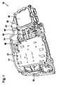
図1に、高圧アプリケーション(図示せず)を動作させるための高圧デバイス10の例示的な実施形態が示されている。図示される例示的な実施形態での高圧デバイス10は、ハウジング14を備える。ハウジング14は、構造的に第1の領域18と第2の領域22とに分割され、2つの領域18、22は互いに分離されている。ここでは見やすいようにハウジングカバー26(図2参照)なしで示されている第1の領域18に、高圧アプリケーションを動作させるための回路構成30が配置される。 An exemplary embodiment of a
第2の領域22には、電圧搬送要素34(図2参照)が配置される。この図では、第2の領域22が接触保護カバー38と共に示されている。ここでは蓋体として形成されているこの接触保護カバー38は、ユーザが電圧搬送要素34に触れないようにする。接触保護カバー38は、ここではねじとして形成されている接続手段42によって固定される。ここで、接続手段42は、ハウジング14によって形成される接続手段のための収容部46に収容される。 A voltage-carrying element 34 (see FIG. 2) is arranged in the
これらの収容部46のうちの2つは、第1の領域18と第2の領域22との両方に隣接する。この例示的な実施形態では、両方の領域18、22に隣接するこれらの収容部46のうちの1つに検出手段50が配置され、検出手段50は、第1の領域18に位置決めされ、第1の領域18には、高圧アプリケーションを動作させるための回路構成30も配置される。 Two of these
検出手段50は、この例示的な実施形態ではセンサとして形成されている。このセンサ50は、信号線54を介して、回路構成30に配置された切断デバイス58と接続されている。回路構成30と同じ領域18内検出手段50を配置することにより、回路構成30、したがって切断デバイス58への信号線54の簡単な接続が保証される。 The detection means 50 are formed as sensors in this exemplary embodiment. This
図2は、接触保護カバー38が開かれた状態での図1による高圧デバイス10の例示的な実施形態を示す。この図では、第1の領域18を覆うハウジングカバー26がハウジング14に取り付けられているが、接触保護カバー38は示されておらず、したがって第2の領域22内を見ることができる。接触保護カバー38を取り外す前に、4つの接続手段42が解除された。ここで、接続手段42の解除が検出手段50によって認識され、それにより電圧搬送要素34が高圧ネットワークから切り離された。 FIG. 2 shows an exemplary embodiment of the
図2には、任意選択のキャップ62が示されている。このキャップ62は、高圧デバイス10の動作状態において、ここでは接点として形成されている電圧搬送要素34に被せて配置され、既に上方に倒されている。これにより、電圧搬送要素34へのアクセスが可能にされる。この位置で、導電体(図示せず)を高圧デバイス10の開口部66に挿入し、電圧搬送要素34と接触させることができる。 An
図3は、接続手段42の解除前後の検出手段50の動作原理の例示的な実施形態を示す。ここではホールセンサとして形成された検出手段50に基づいて動作原理を明らかにする。ここで、図3Aは、接続手段42が解除される前の状態を示す。ここで、この例示的実施形態では、収容部46は、接続手段42のためのねじ山68を形成する。ここで、検出手段50は、収容部46の高さに配置され、接続手段42は、挿入状態で、検出手段50によって形成される測定位置70の領域内にある。これにより、検出手段50は、接続手段42の存在を認識する。 FIG. 3 shows an exemplary embodiment of the operating principle of the detection means 50 before and after the connection means 42 are released. The principle of operation will now be clarified on the basis of the detection means 50 embodied as Hall sensors. Here, FIG. 3A shows the state before the connection means 42 is released. Here, in this exemplary embodiment, the
図3Bには、接続手段42が解除された後の状態が示されている。接続手段42が測定位置70の領域から出るとき、検出手段50は、測定値の変化に基づいて、接続手段42が取り外される、または取り外されたことを確認する。これにより、検出手段50は、信号線54を介して信号74を切断デバイス58に送り、接触保護カバー38が取り外される前に電圧搬送要素34を高圧ネットワークから切り離すことができるようにする。 FIG. 3B shows the state after the connection means 42 have been released. When the connection means 42 leaves the area of the
Claims (8)
Translated fromJapanese少なくとも1つの電圧搬送要素(34)のための接触保護カバー(38)の開放を認識するための検出手段(50)であって、検出手段(50)によって、前記接触保護カバー(38)の完全な取外しの前に信号(74)を出力可能である、検出手段(50)と、
前記検出手段(50)に接続され、前記検出手段(50)の前記出力信号(74)に基づいて、前記電圧搬送要素(34)を高圧ネットワークから切り離すことができる切断デバイス(58)と、を少なくとも備え、
前記検出手段(50)が、前記接触保護カバー(38)を固定する少なくとも1つの接続手段(42)に配置されるので、前記接触保護カバー(38)の取外しを確認するために前記接続手段(42)の解除を検出可能であり、
前記切断デバイス(58)と前記電圧搬送要素(34)とが、前記高圧デバイス(10)の構造的に互いに分離された領域(18、22)に配置される、
ことを特徴とする高圧デバイス(10)。A high voltage device (10) for operating high voltage applications, comprising:
Detection means (50) for recognizing the opening of a contact protection cover (38) for at least one voltage-carrying element (34), the detection means (50) indicating the completeness of said contact protection cover (38). detection means (50) capable of outputting a signal (74) prior to unloading;
a disconnecting device (58) connected to said detection means (50) and capable of disconnecting said voltage-carrying element (34) from a high voltage network based on said output signal (74) of said detection means (50); at least prepare
Said detection means (50) are arranged in at least one connection means (42) fixing said contact protection cover (38) so that said connection means ( 42)is detectable,
said cutting device (58) and said voltage carrying element (34) are located in structurally separated regions (18, 22) of said high voltage device (10);
A high voltage device (10), characterized in that:
Applications Claiming Priority (3)
| Application Number | Priority Date | Filing Date | Title |
|---|---|---|---|
| DE102018221908.7 | 2018-12-17 | ||
| DE102018221908.7ADE102018221908A1 (en) | 2018-12-17 | 2018-12-17 | High-voltage device for operating a high-voltage application |
| PCT/EP2019/084576WO2020126727A1 (en) | 2018-12-17 | 2019-12-11 | High-voltage device for the operation of a high-voltage application |
Publications (2)
| Publication Number | Publication Date |
|---|---|
| JP2022513261A JP2022513261A (en) | 2022-02-07 |
| JP7174855B2true JP7174855B2 (en) | 2022-11-17 |
Family
ID=69137835
Family Applications (1)
| Application Number | Title | Priority Date | Filing Date |
|---|---|---|---|
| JP2021534679AActiveJP7174855B2 (en) | 2018-12-17 | 2019-12-11 | High pressure devices for operating high pressure applications |
Country Status (5)
| Country | Link |
|---|---|
| EP (1) | EP3898312B1 (en) |
| JP (1) | JP7174855B2 (en) |
| CN (1) | CN113165527B (en) |
| DE (1) | DE102018221908A1 (en) |
| WO (1) | WO2020126727A1 (en) |
Families Citing this family (2)
| Publication number | Priority date | Publication date | Assignee | Title |
|---|---|---|---|---|
| CN117325705A (en)* | 2023-09-28 | 2024-01-02 | 东风华神汽车有限公司 | Safety disassembly system and method for power battery and pure electric vehicle |
| DE102023210273A1 (en)* | 2023-10-19 | 2025-04-24 | Zf Friedrichshafen Ag | High-voltage device |
Citations (3)
| Publication number | Priority date | Publication date | Assignee | Title |
|---|---|---|---|---|
| JP2015115988A (en) | 2013-12-09 | 2015-06-22 | トヨタ自動車株式会社 | On-vehicle electrical equipment |
| JP2015221979A (en) | 2014-05-23 | 2015-12-10 | Kyb株式会社 | Electric storage device, hybrid construction machine with the same, and control method of the same |
| US20170362856A1 (en) | 2016-06-16 | 2017-12-21 | Spectrum Brands, Inc. | Strike plate with bolt sensing feature |
Family Cites Families (17)
| Publication number | Priority date | Publication date | Assignee | Title |
|---|---|---|---|---|
| JPH0937562A (en)* | 1995-07-17 | 1997-02-07 | Mitsubishi Electric Corp | Inverter device |
| JPH11132215A (en)* | 1997-10-27 | 1999-05-18 | Nippon Signal Co Ltd:The | Device for confirming fastening of fastening tool |
| JP3956814B2 (en)* | 2002-09-18 | 2007-08-08 | トヨタ自動車株式会社 | High voltage equipment storage box |
| FR2873514B1 (en)* | 2004-07-20 | 2006-11-17 | Virax Sa | LINEAR PORTABLE ACTUATOR AND METHOD FOR LIMITING THE MAXIMUM EFFORT OF AN ENGINE OF SUCH ACTUATOR |
| CN100593481C (en)* | 2006-03-29 | 2010-03-10 | 日产自动车株式会社 | Apparatus and method for controlling braking force distribution during vehicle collision |
| DE102006050180A1 (en)* | 2006-10-25 | 2008-04-30 | Daimler Ag | Electric circuit e.g. alternating current circuit, and interlock-cycle closing device for use in motor vehicle, has housing cover that takes closing and opening positions in which interlock-cycle is closed and interrupted, respectively |
| CN101521265A (en)* | 2008-10-10 | 2009-09-02 | 比亚迪股份有限公司 | Power battery pack for electric vehicle and battery system thereof |
| DE102009038168B4 (en)* | 2009-08-20 | 2014-05-28 | Continental Automotive Gmbh | Current bridging element for releasably closing a circuit |
| DE102011078332A1 (en)* | 2011-06-29 | 2013-01-03 | Robert Bosch Gmbh | safety device |
| DE102011108447B4 (en)* | 2011-07-23 | 2016-11-24 | Volkswagen Ag | Method and system for detecting a change in a connection state of two connection elements for a vehicle |
| DE102011080003A1 (en)* | 2011-07-28 | 2013-01-31 | Schaeffler Technologies AG & Co. KG | Safety circuit with current conducting screw |
| CN102398524B (en)* | 2011-11-17 | 2014-03-26 | 中航锂电(洛阳)有限公司 | Power management device for electromobile |
| US9139097B2 (en)* | 2012-01-05 | 2015-09-22 | Remy Technologies, Llc | Safety cover with integrated magnet for reed switch |
| DE102012008680A1 (en)* | 2012-04-28 | 2013-10-31 | Audi Ag | Vehicle and method for safe shutdown of high voltage generating devices in an accident |
| DE102012214114A1 (en) | 2012-08-09 | 2014-02-13 | Robert Bosch Gmbh | Safety system for vehicles to reduce the risk of electric shock from a battery |
| US9455564B2 (en)* | 2014-02-21 | 2016-09-27 | General Electric Company | Current and voltage module and methods of monitoring current and voltage in power distribution systems |
| DE102014006343A1 (en)* | 2014-04-30 | 2015-11-05 | Daimler Ag | Battery housing for a motor vehicle battery |
- 2018
- 2018-12-17DEDE102018221908.7Apatent/DE102018221908A1/enactivePending
- 2019
- 2019-12-11EPEP19832296.8Apatent/EP3898312B1/enactiveActive
- 2019-12-11JPJP2021534679Apatent/JP7174855B2/enactiveActive
- 2019-12-11WOPCT/EP2019/084576patent/WO2020126727A1/ennot_activeCeased
- 2019-12-11CNCN201980083286.5Apatent/CN113165527B/enactiveActive
Patent Citations (3)
| Publication number | Priority date | Publication date | Assignee | Title |
|---|---|---|---|---|
| JP2015115988A (en) | 2013-12-09 | 2015-06-22 | トヨタ自動車株式会社 | On-vehicle electrical equipment |
| JP2015221979A (en) | 2014-05-23 | 2015-12-10 | Kyb株式会社 | Electric storage device, hybrid construction machine with the same, and control method of the same |
| US20170362856A1 (en) | 2016-06-16 | 2017-12-21 | Spectrum Brands, Inc. | Strike plate with bolt sensing feature |
Also Published As
| Publication number | Publication date |
|---|---|
| WO2020126727A1 (en) | 2020-06-25 |
| EP3898312A1 (en) | 2021-10-27 |
| CN113165527B (en) | 2024-04-16 |
| EP3898312B1 (en) | 2025-10-08 |
| DE102018221908A1 (en) | 2020-06-18 |
| CN113165527A (en) | 2021-07-23 |
| JP2022513261A (en) | 2022-02-07 |
Similar Documents
| Publication | Publication Date | Title |
|---|---|---|
| JP7174855B2 (en) | High pressure devices for operating high pressure applications | |
| US8289026B2 (en) | Recording device for recording the switch state of an electromagnetic switch device | |
| US7855630B2 (en) | Fuse state indicator systems | |
| JP5959707B2 (en) | Temperature detection in the plug by superimposing the test frequency | |
| US9842717B2 (en) | High speed closing switch | |
| CN103107506A (en) | Installation device with a current sensor unit | |
| CN101322209B (en) | Method for monitoring protection apparatus connected on upriver part of switch apparatus | |
| CN109155210B (en) | Electronic device disconnected | |
| CN113169475B (en) | High-voltage device | |
| CN104835690B (en) | trigger device | |
| US10083787B1 (en) | Current converter with interchangeable head | |
| CN103715561B (en) | Including with can independent test contact integrated security relay terminal plate | |
| CN107438930B (en) | Current distribution system for being connected on AC network | |
| CN113012960A (en) | Electrical device and system comprising an electric machine and an electrical device | |
| CN104810788B (en) | External control of electromagnetic triggers | |
| CN102484018B (en) | Attachment module for detection of a switching state of an electromagnetic switching device | |
| CN106898525B (en) | Electrical switching device comprising a switching mechanism and at least one auxiliary module | |
| KR101670304B1 (en) | Vacuum Circuit Breaker with Temperature Monitoring | |
| US9548561B2 (en) | System comprising a base and a hot unpluggable module | |
| EP1270336A2 (en) | Fuse and relay box in a motor vehicle | |
| EP3675290B1 (en) | Electrical outlet and method | |
| JP6706075B2 (en) | Control center | |
| HK1211704B (en) | Current transformer and load interrupter having such a current transformer | |
| KR20170086731A (en) | Distribution Panel |
Legal Events
| Date | Code | Title | Description |
|---|---|---|---|
| A621 | Written request for application examination | Free format text:JAPANESE INTERMEDIATE CODE: A621 Effective date:20210616 | |
| A977 | Report on retrieval | Free format text:JAPANESE INTERMEDIATE CODE: A971007 Effective date:20220624 | |
| A131 | Notification of reasons for refusal | Free format text:JAPANESE INTERMEDIATE CODE: A131 Effective date:20220705 | |
| A521 | Request for written amendment filed | Free format text:JAPANESE INTERMEDIATE CODE: A523 Effective date:20220912 | |
| TRDD | Decision of grant or rejection written | ||
| A01 | Written decision to grant a patent or to grant a registration (utility model) | Free format text:JAPANESE INTERMEDIATE CODE: A01 Effective date:20221026 | |
| A61 | First payment of annual fees (during grant procedure) | Free format text:JAPANESE INTERMEDIATE CODE: A61 Effective date:20221107 | |
| R150 | Certificate of patent or registration of utility model | Ref document number:7174855 Country of ref document:JP Free format text:JAPANESE INTERMEDIATE CODE: R150 |