JP7174771B2 - Active interference cancellation device, signal isolation control device and method for actively canceling interference - Google Patents
Active interference cancellation device, signal isolation control device and method for actively canceling interferenceDownload PDFInfo
- Publication number
- JP7174771B2 JP7174771B2JP2020552292AJP2020552292AJP7174771B2JP 7174771 B2JP7174771 B2JP 7174771B2JP 2020552292 AJP2020552292 AJP 2020552292AJP 2020552292 AJP2020552292 AJP 2020552292AJP 7174771 B2JP7174771 B2JP 7174771B2
- Authority
- JP
- Japan
- Prior art keywords
- waveform
- chain
- frequency
- transfer function
- transmitter chain
- Prior art date
- Legal status (The legal status is an assumption and is not a legal conclusion. Google has not performed a legal analysis and makes no representation as to the accuracy of the status listed.)
- Active
Links
- 238000000034methodMethods0.000titleclaimsdescription22
- 238000002955isolationMethods0.000titleclaimsdescription20
- 238000012546transferMethods0.000claimsdescription91
- 230000003044adaptive effectEffects0.000claimsdescription66
- 238000012545processingMethods0.000claimsdescription44
- 230000006854communicationEffects0.000claimsdescription27
- 238000004891communicationMethods0.000claimsdescription27
- 230000008878couplingEffects0.000claimsdescription11
- 238000010168coupling processMethods0.000claimsdescription11
- 238000005859coupling reactionMethods0.000claimsdescription11
- 230000002123temporal effectEffects0.000claimsdescription9
- 239000002131composite materialSubstances0.000claimsdescription5
- 230000006870functionEffects0.000description68
- 125000004122cyclic groupChemical group0.000description13
- 230000005540biological transmissionEffects0.000description11
- 230000036961partial effectEffects0.000description10
- 238000010586diagramMethods0.000description8
- 238000010079rubber tappingMethods0.000description6
- 238000003860storageMethods0.000description6
- 238000004590computer programMethods0.000description5
- 230000002452interceptive effectEffects0.000description4
- 238000013507mappingMethods0.000description4
- 239000000969carrierSubstances0.000description3
- 230000008859changeEffects0.000description3
- 230000003287optical effectEffects0.000description3
- 230000011664signalingEffects0.000description3
- 230000009977dual effectEffects0.000description2
- 230000000670limiting effectEffects0.000description2
- 238000004519manufacturing processMethods0.000description2
- 230000007246mechanismEffects0.000description2
- 238000002360preparation methodMethods0.000description2
- 230000002441reversible effectEffects0.000description2
- 238000001228spectrumMethods0.000description2
- 238000010897surface acoustic wave methodMethods0.000description2
- 238000012360testing methodMethods0.000description2
- 238000013459approachMethods0.000description1
- 230000004888barrier functionEffects0.000description1
- 230000006399behaviorEffects0.000description1
- 230000007175bidirectional communicationEffects0.000description1
- 238000004364calculation methodMethods0.000description1
- 230000010267cellular communicationEffects0.000description1
- 239000007795chemical reaction productSubstances0.000description1
- 230000000694effectsEffects0.000description1
- 238000011067equilibrationMethods0.000description1
- 230000007274generation of a signal involved in cell-cell signalingEffects0.000description1
- 238000003780insertionMethods0.000description1
- 230000037431insertionEffects0.000description1
- 230000003993interactionEffects0.000description1
- 230000007774longtermEffects0.000description1
- 230000008569processEffects0.000description1
- 230000001902propagating effectEffects0.000description1
- 230000005855radiationEffects0.000description1
- 230000002829reductive effectEffects0.000description1
- 230000001052transient effectEffects0.000description1
Images


Classifications
- H—ELECTRICITY
- H04—ELECTRIC COMMUNICATION TECHNIQUE
- H04B—TRANSMISSION
- H04B1/00—Details of transmission systems, not covered by a single one of groups H04B3/00 - H04B13/00; Details of transmission systems not characterised by the medium used for transmission
- H04B1/38—Transceivers, i.e. devices in which transmitter and receiver form a structural unit and in which at least one part is used for functions of transmitting and receiving
- H04B1/40—Circuits
- H04B1/50—Circuits using different frequencies for the two directions of communication
- H04B1/52—Hybrid arrangements, i.e. arrangements for transition from single-path two-direction transmission to single-direction transmission on each of two paths or vice versa
- H04B1/525—Hybrid arrangements, i.e. arrangements for transition from single-path two-direction transmission to single-direction transmission on each of two paths or vice versa with means for reducing leakage of transmitter signal into the receiver
- H—ELECTRICITY
- H04—ELECTRIC COMMUNICATION TECHNIQUE
- H04B—TRANSMISSION
- H04B1/00—Details of transmission systems, not covered by a single one of groups H04B3/00 - H04B13/00; Details of transmission systems not characterised by the medium used for transmission
- H04B1/38—Transceivers, i.e. devices in which transmitter and receiver form a structural unit and in which at least one part is used for functions of transmitting and receiving
- H04B1/40—Circuits
- H04B1/54—Circuits using the same frequency for two directions of communication
- H04B1/58—Hybrid arrangements, i.e. arrangements for transition from single-path two-direction transmission to single-direction transmission on each of two paths or vice versa
- H04B1/581—Hybrid arrangements, i.e. arrangements for transition from single-path two-direction transmission to single-direction transmission on each of two paths or vice versa using a transformer
- H04B1/582—Hybrid arrangements, i.e. arrangements for transition from single-path two-direction transmission to single-direction transmission on each of two paths or vice versa using a transformer with automatic balancing
Landscapes
- Engineering & Computer Science (AREA)
- Computer Networks & Wireless Communication (AREA)
- Signal Processing (AREA)
- Power Engineering (AREA)
- Cable Transmission Systems, Equalization Of Radio And Reduction Of Echo (AREA)
- Transceivers (AREA)
- Noise Elimination (AREA)
Description
Translated fromJapanese本発明は、例えば、受信信号への適用のための除去信号を発生するための補助送信器チェーンを備える種類のアクティブ干渉除去装置に関する。本発明は、また、例えば、上述されたアクティブ干渉除去装置と併せて利用される、二重化のためのハイブリッド回路を備える種類の信号絶縁制御装置に関する。本発明は、さらに、干渉をアクティブ的に除去する方法であって、本方法が、例えば、補助送信器チェーンが、受信信号に適用される除去信号を発生することを含む種類のものである、方法に関する。 The present invention relates to an active interference cancellation device, for example of the kind comprising an auxiliary transmitter chain for generating a cancellation signal for application to a received signal. The invention also relates to a signal isolation control device of the kind comprising a hybrid circuit for duplication, for example used in conjunction with the active interference cancellation device described above. The present invention further provides a method of actively canceling interference, the method being of the type comprising, for example, an auxiliary transmitter chain generating a cancellation signal to be applied to the received signal. Regarding the method.
いくつかの無線通信システムでは、このようなシステムは、ネットワーク・インフラストラクチャ、および例えば、ポータブル通信デバイスであることができる、ユーザ機器を含む。このような通信デバイスは、通例、同じアンテナまたはアンテナのセットを通じて信号を受信および送信する。これは、デバイスが、入力信号および出力信号を、前者が後者によってのまれないよう分離することを可能にするために、何らかの形の二重化方式が必要とされることを意味する。この点においては、時分割二重化(Time-Division Duplexing、TDD)および周波数分割二重化(Frequency-Division Duplexing、FDD)がどちらもよく知られた二重化方式である。 In some wireless communication systems, such system includes network infrastructure and user equipment, which can be, for example, a portable communication device. Such communication devices typically receive and transmit signals through the same antenna or set of antennas. This means that some form of duplexing scheme is required to allow the device to separate the input and output signals so that the former cannot be overwhelmed by the latter. In this regard, both Time-Division Duplexing (TDD) and Frequency-Division Duplexing (FDD) are well-known duplexing schemes.
通信システムを動作させるべき電波スペクトルの可用性が制約因子となることが知られている。いわゆる4G、またはロング・ターム・エボリューション(Long Term Evolution、LTE)は既存の2Gおよび3G通信システムの後継である。実際に、LTE準拠ネットワークは多くの国ですでに運用されている。歴史的理由のために、LTE規格の3Gパートナーシップ・プロジェクト(3G Partnership Project、3GPP)Rel 15において規定された、LTE規格のための60個のLTE動作周波数帯域が存在し、そのうち35個はFDD動作を必要とする。さらなるモバイル・ブロードバンド・スペクトルが様々な地域における政府によって利用可能にされるため、より多くの帯域がLTE規格の後のリリースにおいて規定される見込みである。 It is known that the availability of radio spectrum to operate a communication system is a limiting factor. So-called 4G, or Long Term Evolution (LTE), is the successor to existing 2G and 3G communication systems. In fact, LTE-compliant networks are already in operation in many countries. For historical reasons, there are 60 LTE operating frequency bands for the LTE standard, 35 of which are for FDD operation, as defined in the 3G Partnership Project (3GPP) Rel 15 of the LTE standard. need. More bands are expected to be defined in later releases of the LTE standard as more mobile broadband spectrum is made available by governments in various regions.
FDD無線動作では、一方はアップリンク送信のため、および一方はダウンリンク送信のための、異なる周波数における2つの別個の搬送波が存在する。ダウンリンク送信とアップリンク送信との間の絶縁は、通常、二信化フィルタ(diplexing filter)(デュプレクサまたはダイプレクサ)と呼ばれる送信/受信フィルタによって達成される。これらのフィルタは、通例、送信および受信信号を分離し、これにより、送信信号が受信信号と干渉するのを防止するために、一方は受信周波数帯域を中心とし、他方は送信周波数帯域を中心とする、2つの高度に選択的なフィルタとして実施される。表面弾性波(Surface Acoustic Wave、SAW)フィルタなどの、音響共振器フィルタが、通例、二重化フィルタに必要とされる低い挿入損失および急峻な減衰をもたらすために用いられる。これらは個々に小型で安価であるものの、複数の周波数帯域をサポートするべき通信デバイスは、サポートされるべき周波数帯域ごとに1つの二信化フィルタ、および二重化フィルタがアンテナを共有することができるよう、周波数帯域の間の選択のためのさらなる無線周波数(Radio Frequency、RF)スイッチングを必要とする。他の欠点は二信化フィルタの使用に関連付けられ、これは、二信化を目的とする代替解決策の探索を余儀なくさせる。 In FDD radio operation, there are two separate carriers at different frequencies, one for uplink transmission and one for downlink transmission. Isolation between downlink and uplink transmissions is achieved by transmit/receive filters, commonly referred to as diplexing filters (duplexers or diplexers). These filters are typically one centered on the receive frequency band and the other centered on the transmit frequency band to separate the transmit and receive signals, thereby preventing the transmit signal from interfering with the receive signal. are implemented as two highly selective filters. Acoustic resonator filters, such as Surface Acoustic Wave (SAW) filters, are commonly used to provide the low insertion loss and steep attenuation required for duplex filters. Although they are individually small and inexpensive, communication devices that are to support multiple frequency bands may use dual filters, one for each frequency band to be supported, and dual filters to share an antenna. , requires additional Radio Frequency (RF) switching for selection between frequency bands. Another drawback is associated with the use of dualizing filters, which forces the search for alternative solutions aimed at dualizing.
多くのデバイス製造業者は、単純に、動作周波数帯域の異なるセットをサポートする異なって構成されたデバイスを設計し、製造することによって、これらの欠点を回避している。それゆえ、製造業者は、異なる周波数帯域の組合せを有する異なる地域グループ内で各々動作可能である広範なデバイスを提供している。したがって、上述のフィルタの必要性を取り除くことは、「ワールド・フォン」の製造への障壁を取り払うことになり、その恩恵は規模の経済を携帯電話産業にもたらし、国際旅行者への不便を軽減するであろうことが理解され得る。 Many device manufacturers circumvent these shortcomings by simply designing and manufacturing differently configured devices that support different sets of operating frequency bands. Therefore, manufacturers offer a wide range of devices, each capable of operating within different regional groups having different frequency band combinations. Thus, removing the need for the above filters would remove a barrier to the manufacture of "world phones", the benefits of which would bring economies of scale to the mobile phone industry and reduce inconvenience to international travelers. It can be understood that
したがって、固定された調整済みのダイプレクサを、複数の、好ましくは全ての、周波数帯域をサポートすることができる柔軟なデバイスと置き換えることができる解決策への莫大な市場需要がある。 Therefore, there is a huge market demand for a solution that can replace fixed, tuned diplexers with flexible devices that can support multiple, preferably all, frequency bands.
さらに、受信器を送信信号から十分に絶縁することができる好適な二重化方式を採用することによって、信号が共通周波数帯域内で同時に送信および受信されることができ、これは、双方向通信リンクにおいて、TDDおよびFDD二重化方式と比べて、最大2倍の大きさの容量をもたらすことができる。 Furthermore, by employing a suitable duplexing scheme that can sufficiently isolate the receiver from the transmitted signal, signals can be transmitted and received simultaneously within a common frequency band, which is useful in bi-directional communication links. , TDD and FDD duplexing schemes can yield up to twice as much capacity.
代替的な二重化解決策は、いわゆるハイブリッド分岐またはハイブリッド回路を採用する。これは、送信線路内で順方向および逆方向の波向を分離することができる4ポート・ネットワークである。ハイブリッド分岐は、変成器、導波管(「マジックT」)、またはマイクロストリップ(「方向性結合器」)を用いることを含む、多数の仕方で作製され得る。ハイブリッド分岐はまた、現代の電子アナログ有線電話の場合のように、アクティブ回路を用いて作製され得る。 An alternative duplexing solution employs so-called hybrid branches or hybrid circuits. This is a four-port network capable of separating forward and reverse wave directions in the transmission line. Hybrid branches can be made in a number of ways, including using transformers, waveguides ("magic T's"), or microstrips ("directional couplers"). Hybrid branches can also be made with active circuitry, as in modern electronic analog wireline telephones.
ハイブリッド分岐は、通例、第1の(送信)ポート、第2の(アンテナ)ポート、第3の(受信)ポート、および第4の(平衡)ポートを備える。理想的なハイブリッド分岐の動作においては、送信ポートにおいて入射する全電力がアンテナ・ポートと平衡ポートとの間で分割される。同様に、受信ポートに入射する全電力がアンテナ・ポートと平衡ポートとの間で分割される。したがって、デバイスは無損失であり、可逆であり、各々を中心として同様の特性を有する2つの対称面を有する。 A hybrid branch typically comprises a first (transmit) port, a second (antenna) port, a third (receive) port and a fourth (balanced) port. In ideal hybrid branch operation, the total power incident on the transmit port is split between the antenna port and the balanced port. Similarly, the total power incident on the receive port is split between the antenna port and the balanced port. The device is therefore lossless, reversible, and has two planes of symmetry with similar properties about each.
理論上のハイブリッド分岐は、デュプレクサとして用いられるとき、その送信ポートに結合された送信器チェーンの電力増幅器、および受信ポートに結合された低雑音増幅器を有する。電力増幅器によって送信ポートにおいて印加された送信電力は、上述されたように、アンテナ・ポートと平衡ポートとの間で分割され、低雑音増幅器は絶縁されている、すなわち、アンテナ・ポートおよび平衡ポートにおける反射係数が平衡している限り、受信器内への送信信号の漏れは存在しない。 A theoretical hybrid branch, when used as a duplexer, has the power amplifier of the transmitter chain coupled to its transmit port and the low noise amplifier coupled to its receive port. The transmit power applied at the transmit port by the power amplifier is split between the antenna port and the balanced port, as described above, and the low noise amplifier is isolated, i.e. As long as the reflection coefficients are balanced, there is no leakage of the transmitted signal into the receiver.
しかし、実際には、デュプレクサとしてのハイブリッド分岐の使用はいくつかの欠点にも悩まされる。第1に、アンテナのインピーダンス、およびそれゆえ、ひいては、アンテナ・ポートにおけるインピーダンスは、通例、時間領域および周波数領域の双方における変化を呈する。アンテナのインピーダンスは、例えば、アンテナの付近で動く物体のために、時間と共に変化し得、それゆえ、これらの変化に対応するために、平衡ポートにおけるインピーダンスをアンテナ・ポートにおけるインピーダンスに動的に適応させることが必要である。アンテナ・インピーダンスはまた、通例、周波数と共に変化し、それゆえ、関心のある特定の周波数において平衡を得るために、平衡ポートにおけるインピーダンスは適宜適応させられなければならず、良好な平衡は、十分に広いシステム帯域幅、例えば、LTEチャンネルのために必要とされる20MHzにわたって達成することが難しくなり得る。さらに、絶縁帯域幅、すなわち、適切な絶縁が達成され得る帯域幅を増大させることは、可変平衡化インピーダンス回路の複雑さの増大を必要とし、これはデバイスのサイズおよびコストを増大させることになる。 In practice, however, the use of hybrid branches as duplexers also suffers from several drawbacks. First, the impedance of the antenna, and hence the impedance at the antenna ports, typically exhibit variations in both the time and frequency domains. The impedance of an antenna may change over time due to, for example, objects moving in the vicinity of the antenna, so dynamically adapting the impedance at the balanced port to the impedance at the antenna port to accommodate these changes. It is necessary to let Antenna impedance also typically varies with frequency, so to obtain balance at the particular frequency of interest, the impedance at the balance port must be adapted accordingly; Achieving over a wide system bandwidth, eg, 20 MHz required for LTE channels can be difficult. Furthermore, increasing the isolation bandwidth, ie the bandwidth over which adequate isolation can be achieved, requires increasing the complexity of the variable balanced impedance circuit, which increases the size and cost of the device. .
第2に、他のカップリング機構が、ハイブリッド分岐の送信ポートから受信ポートへの送信信号のうちのいくらかの漏れを生じさせる。それゆえ、送信ポートからの受信ポートの絶縁が制約される。 Second, other coupling mechanisms cause leakage of some of the transmitted signal from the transmit port to the receive port of the hybrid branch. Therefore, the isolation of the receive port from the transmit port is constrained.
デュプレクサとしてのハイブリッド分岐の使用に関連付けられる上述の欠点にもかかわらず、不利点を取り除く、または少なくとも軽減する試みがなされた。例えば、「Optimum Single Antenna Full Duplex Using Hybrid Junctions」(Laughlin, Beach, Morris and Haine, IEEE Journal of Selected Areas In Communications, Vol.32,No.9, September 2014,1653~1661頁)は、周波数と共に幅広く変化することができるインピーダンスを有し、(離調近接効果が存在しない限りにおいて)10dB最小のオーダーのものになる可能性が高い反射損失を有する任意アンテナを考究している。これは、広範な最終製品内に組み込まれ得、場合によっては、未知の長さの送信線路を通じて接続され得るであろうトランシーバ回路のための実用的な現実である。以上において参照された文献では、いわゆるハイブリッド分岐の電気的平衡(Electrical Balance、EB)が提案されている。 Despite the above-mentioned drawbacks associated with the use of hybrid branches as duplexers, attempts have been made to eliminate or at least mitigate the drawbacks.例えば、「Optimum Single Antenna Full Duplex Using Hybrid Junctions」(Laughlin, Beach, Morris and Haine, IEEE Journal of Selected Areas In Communications, Vol.32,No.9, September 2014,1653~1661頁)は、周波数と共に幅広くWe consider an arbitrary antenna with a variable impedance and a return loss likely to be of the order of 10 dB minimum (unless detuning proximity effects are present). This is a practical reality for transceiver circuits that may be incorporated into a wide variety of end products and possibly connected through transmission lines of unknown length. In the documents referred to above, a so-called Hybrid Branch Electrical Balance (EB) is proposed.
国際公開第2016/128032号は、主送信器チェーンおよび補助送信器チェーンを採用した信号絶縁装置を開示している。主送信器チェーンは、ハイブリッド回路の入力ノードに動作可能に結合された出力ノードを有し、ハイブリッド回路は二重通信のために用いられる。ハイブリッド回路の出力ノードは、とりわけ、ハイブリッド回路のアンテナノードに動作可能に結合されたアンテナを介して受信されるRF通信信号を受信するための受信器チェーンの入力に動作可能に結合されている。補助送信器チェーンは、主送信器チェーン内のタッピング信号端子に動作可能に結合された入力ノードを含み、主送信信号が、アンテナを介したRF出力信号としての送信に備えるよう処理されている際に、主送信器チェーンを通って伝搬する主送信信号をタッピングするように構成されている。補助送信器チェーンは、タッピングされた主送信信号を、それが主送信器チェーンによって主送信信号と同様の仕方で処理される前に変更するために設定され得る係数を有する適応フィルタユニットを含む。主送信信号の適応されたバージョンは、受信器チェーンの受信帯域内の、入力ノードからハイブリッド回路の出力ノードへ漏れている信号成分を除去するためにハイブリッド回路の平衡ノードに適用される除去信号をもたらす。 WO2016/128032 discloses a signal isolator employing a main transmitter chain and an auxiliary transmitter chain. A main transmitter chain has an output node operatively coupled to the input node of the hybrid circuit, the hybrid circuit being used for duplex communication. An output node of the hybrid circuit is operatively coupled, among other things, to an input of a receiver chain for receiving RF communication signals received via an antenna operably coupled to the antenna node of the hybrid circuit. The auxiliary transmitter chain includes an input node operably coupled to the tapping signal terminal in the main transmitter chain when the main transmit signal is being processed in preparation for transmission as an RF output signal over the antenna. is configured to tap the main transmit signal propagating through the main transmitter chain. The auxiliary transmitter chain includes an adaptive filter unit having coefficients that can be set to modify the tapped main transmit signal before it is processed by the main transmitter chain in a manner similar to the main transmit signal. The adapted version of the main transmit signal is a cancellation signal applied to the balance node of the hybrid circuit to remove signal components leaking from the input node to the output node of the hybrid circuit within the receive band of the receiver chain. Bring.
この点について、主送信器チェーンおよび補助送信器チェーンから受信器チェーンへ通信される信号を考慮すると、信号を主送信器から受信器へ、および補助送信器から受信器へ結合する信号カップリング機構、例えば、電気および電磁結合が存在する。この結合は、どちらも適応フィルタのための係数を決定するための推定を必要とする、自己干渉伝達関数および除去伝達関数によってそれぞれ定量化されることができる。自己干渉伝達関数および除去伝達関数を推定するために、複数の副搬送波を各々含む、それぞれのパイロット信号を発生することが知られており、副搬送波は周波数が分離されている。パイロット信号は、自己干渉伝達関数および除去伝達関数を包括的な仕方で測定することが可能になるために、信号絶縁装置が動作する通信システムの副搬送波を各々含む。さらに、それぞれのパイロット信号は、同じ副搬送波に関する適応フィルタのフィルタ係数を決定することが可能になるために、同じ搬送波信号を含む。したがって、受信器チェーンを用いて送信器チェーンによって発生されたパイロット信号を測定し、受信器チェーンを用いて補助送信器チェーンによって発生されたパイロット信号を測定するためには、パイロット信号が同じ副搬送波を各々含むため、それぞれのパイロット信号を時間的に別個に送信することが必要である。他の仕方で行うことは、2つのパイロット信号が互いに干渉する結果をもたらすことになる。 In this regard, considering the signals communicated from the main transmitter chain and the auxiliary transmitter chain to the receiver chain, the signal coupling mechanism that couples the signals from the main transmitter to the receiver and from the auxiliary transmitter to the receiver , for example, electrical and electromagnetic coupling exists. This coupling can be quantified by a self-interference transfer function and a cancellation transfer function, respectively, both of which require estimation to determine the coefficients for the adaptive filters. To estimate the self-interference transfer function and the cancellation transfer function, it is known to generate respective pilot signals each comprising a plurality of sub-carriers, the sub-carriers being separated in frequency. The pilot signals each contain a sub-carrier of the communication system in which the signal isolator operates in order to allow the self-interference transfer function and the cancellation transfer function to be measured in a comprehensive manner. Moreover, each pilot signal contains the same carrier signal to allow the filter coefficients of the adaptive filter for the same sub-carrier to be determined. Therefore, in order to use the receiver chain to measure the pilot signal generated by the transmitter chain and the receiver chain to measure the pilot signal generated by the auxiliary transmitter chain, the pilot signals must be on the same subcarrier. , it is necessary to transmit each pilot signal separately in time. Doing otherwise will result in the two pilot signals interfering with each other.
上述のアクティブ除去技法、特に、現在、自己干渉伝達関数が推定される間には補助送信器チェーンが非活動状態になること、および除去伝達関数に関してはその逆のことを必要とする、適応フィルタユニットの構成を採用した通信デバイスの動作速度を最適化することが望まれる。 Active cancellation techniques described above, in particular adaptive filters that currently require the auxiliary transmitter chain to be inactive while the self-interference transfer function is estimated, and vice versa for the cancellation transfer function. It is desirable to optimize the speed of operation of communication devices employing unit configurations.
本発明の第1の態様によれば、送信および受信される信号の二重動作を制御するためのアクティブ干渉除去装置であって、装置が、受信信号入力ノードを含む受信器チェーンと、送信器チェーンタップノードおよび送信器出力ノードを含む送信器チェーンと、送信器チェーンタップノードに動作可能に結合された補助チェーン入力ノードを有する補助送信器チェーンであって、補助送信器チェーンが、適応フィルタユニットおよび除去信号出力を含み、除去信号出力が、受信器チェーンの受信信号入力ノードに動作可能に結合されている、補助送信器チェーンと、補間プロセッサと、を備え、適応フィルタユニットが係数処理ユニットおよび適応フィルタを含み、係数処理ユニットが受信器チェーンおよび適応フィルタに動作可能に結合され、補間プロセッサが、係数処理ユニットと協働するように構成され、送信器チェーンが、使用時に、複数の第1の周波数分離信号を含む第1の波形を発生するように構成され、送信器チェーンと実質的に同時に、補助送信器チェーンが、複数の第2の周波数分離信号を含む第2の波形を発生し、第2の波形を受信信号入力ノードにおいて適用するように構成され、受信器チェーンが、送信器チェーンの出力ノードから受信器チェーンの受信信号入力ノードに結合された波形、および補助送信器チェーンからの第2の波形を含む合成波形を受信するように構成され、第1の波形が、第2の波形の複数の第2の周波数分離信号と周波数が一致する適応フィルタのイコライザ係数の決定のために必要とされる信号を全く含まない、アクティブ干渉除去装置が提供される。 According to a first aspect of the present invention, an active interference cancellation device for controlling the duplex behavior of transmitted and received signals, the device comprising a receiver chain including a received signal input node, a transmitter a transmitter chain including a chain tap node and a transmitter output node, and an auxiliary transmitter chain having an auxiliary chain input node operatively coupled to the transmitter chain tap node, the auxiliary transmitter chain comprising an adaptive filter unit and a cancellation signal output, the cancellation signal output being operatively coupled to a received signal input node of the receiver chain; and an interpolation processor, wherein the adaptive filter unit comprises a coefficient processing unit and an adaptive filter, a coefficient processing unit operatively coupled to the receiver chain and the adaptive filter; an interpolation processor configured to cooperate with the coefficient processing unit; substantially concurrently with the transmitter chain, an auxiliary transmitter chain generating a second waveform comprising a plurality of second frequency-separated signals; , configured to apply a second waveform at a received signal input node, the receiver chain receiving a waveform coupled from the output node of the transmitter chain to the received signal input node of the receiver chain, and from the auxiliary transmitter chain. for determining equalizer coefficients of an adaptive filter configured to receive a composite waveform comprising a second waveform of the first waveform being matched in frequency with a plurality of second frequency separated signals of the second waveform An active interference cancellation device is provided that does not contain any signal required for .
送信器チェーンの出力ノードから受信器チェーンの受信信号入力ノードに結合される波形は電磁結合され得る。 Waveforms coupled from the output node of the transmitter chain to the received signal input node of the receiver chain may be electromagnetically coupled.
第1の波形は複数の第1の副搬送波に対応し得、第2の波形は複数の第2の副搬送波に対応し得、第1および複数の第2の副搬送波は異なり得る。 The first waveform may correspond to multiple first subcarriers, the second waveform may correspond to multiple second subcarriers, and the first and multiple second subcarriers may be different.
第1の波形には、第2の波形の複数の第2の周波数分離信号によって占有される周波数における適応フィルタのイコライザ係数の決定のために必要とされる信号が存在し得ない。 There may be no signals in the first waveform that are needed for determination of the equalizer coefficients of the adaptive filter at frequencies occupied by the plurality of second frequency separated signals of the second waveform.
第2の波形には、第1の波形の複数の第1の周波数分離信号によって占有される周波数における適応フィルタのイコライザ係数の決定のために必要とされる信号が存在し得ない。 There may be no signals in the second waveform that are needed for determination of the equalizer coefficients of the adaptive filter at frequencies occupied by the plurality of first frequency separated signals of the first waveform.
複数の第1の周波数分離信号および複数の第2の周波数分離信号は周波数領域において交互配置され得る。 The plurality of first frequency-separated signals and the plurality of second frequency-separated signals may be interleaved in the frequency domain.
適応フィルタユニットは、送信器チェーンおよび受信器チェーン内およびそれらの間で第1の波形によって経験される変化をモデル化する周波数領域自己干渉伝達関数の係数を推定するように構成され得、適応フィルタは、補助送信器チェーンおよび受信器チェーン内およびそれらの間で第2の波形によって経験される変化をモデル化する周波数領域除去伝達関数の係数を推定するように構成され得、補間プロセッサは、第1の波形に存在しない周波数に関する周波数領域自己干渉伝達関数の係数、および第2の波形に存在しない周波数に関する周波数領域除去伝達関数の係数を推定するように構成され得る。 The adaptive filter unit may be configured to estimate coefficients of a frequency domain self-interference transfer function that models changes experienced by the first waveform in and between the transmitter chain and the receiver chain; may be configured to estimate the coefficients of a frequency domain rejection transfer function that models the changes experienced by the second waveform in and between the auxiliary transmitter and receiver chains, and the interpolation processor may be configured to estimate the coefficients of the frequency domain rejection transfer function, It may be configured to estimate coefficients of a frequency domain self-interference transfer function for frequencies not present in one waveform and coefficients of a frequency domain rejection transfer function for frequencies not present in the second waveform.
第1の波形に存在しない周波数および第2の波形に存在しない周波数は意図的に存在しなくてもよい。 Frequencies not present in the first waveform and frequencies not present in the second waveform may be intentionally absent.
第1の波形は、一連の送信波形から選択されたスペクトル的に不連続な送信波形であり得る。 The first waveform may be a spectrally discrete transmit waveform selected from a series of transmit waveforms.
自己干渉伝達関数は、送信器チェーンおよび受信器チェーン内およびそれらの間で第1の波形によって経験される変化をモデル化し得、除去伝達関数は、補助送信器チェーンおよび受信器チェーン内およびそれらの間で第2の波形によって経験される変化をモデル化し得る。 The self-interference transfer function may model the changes experienced by the first waveform in and between the transmitter and receiver chains, and the cancellation transfer function may model the changes in and between the auxiliary transmitter and receiver chains. We can model the change experienced by the second waveform in between.
自己干渉伝達関数は、送信器チェーン、受信器チェーンによって遂行される第1の波形の処理、および送信器チェーンから受信器チェーンへの第1の波形の結合をモデル化し得、除去伝達関数は、送信器チェーン、受信器チェーン、および相互接続回路によって遂行される第2の波形の処理をモデル化し得る。 The self-interference transfer function may model the transmitter chain, the processing of the first waveform performed by the receiver chain, and the coupling of the first waveform from the transmitter chain to the receiver chain, and the cancellation transfer function may be The processing of the second waveform performed by the transmitter chain, receiver chain, and interconnect circuitry may be modeled.
補間プロセッサは、それぞれ、第1の波形内に存在する隣接する周波数の間にある周波数に関する周波数領域自己干渉伝達関数の係数を推定するように構成され得る。 The interpolation processors may each be configured to estimate coefficients of the frequency domain self-interference transfer function for frequencies that lie between adjacent frequencies present in the first waveform.
それぞれ、第1の波形内に存在する隣接する周波数の間にある周波数は、それぞれ、第1の波形内の隣接する周波数分離信号の間にある周波数であり得る。 Each frequency between adjacent frequencies present in the first waveform may be a frequency between adjacent frequency separated signals in the first waveform.
補間プロセッサは、それぞれ、第2の波形内に存在する隣接する周波数の間にある周波数に関する周波数領域除去伝達関数の係数を推定するように構成され得る。 The interpolation processors may each be configured to estimate coefficients of the frequency domain rejection transfer function for frequencies that lie between adjacent frequencies present in the second waveform.
それぞれ、第2の波形内に存在する隣接する周波数の間にある周波数は、それぞれ、第2の波形内の隣接する周波数分離信号の間にある周波数であり得る。 Each frequency between adjacent frequencies present in the second waveform may be a frequency between adjacent frequency separated signals in the second waveform.
自己干渉伝達関数は、送信器チェーンおよび受信器チェーンのベースバンドおよび無線周波数処理段階を特徴付け得、除去伝達関数は、補助送信器チェーンおよび受信器チェーンのベースバンドおよび無線周波数処理段階を特徴付け得る。 The self-interference transfer function may characterize the baseband and radio frequency processing stages of the transmitter and receiver chains, and the cancellation transfer function characterizes the baseband and radio frequency processing stages of the auxiliary transmitter and receiver chains. obtain.
係数処理ユニットは、推定された周波数領域自己干渉伝達関数および推定された周波数領域除去伝達関数を補間プロセッサから受信するように構成され得、係数処理ユニットは、推定された周波数領域自己干渉伝達関数および推定された周波数領域除去伝達関数を用いて適応フィルタのためのイコライザ係数を算出するように構成され得る。 The coefficient processing unit may be configured to receive the estimated frequency-domain self-interference transfer function and the estimated frequency-domain rejection transfer function from the interpolation processor, the coefficient processing unit receiving the estimated frequency-domain self-interference transfer function and It may be configured to compute equalizer coefficients for the adaptive filter using the estimated frequency domain rejection transfer function.
係数処理ユニットは、推定された周波数領域除去伝達関数による推定された周波数領域自己干渉伝達関数の負号除算によって適応フィルタのフィルタ係数を算出するように構成され得る。 The coefficient processing unit may be configured to calculate filter coefficients of the adaptive filter by negative division of the estimated frequency domain self-interference transfer function by the estimated frequency domain rejection transfer function.
係数処理ユニットは、使用時に、算出されたイコライザ・フィルタ係数を用いて適応フィルタの係数を変更するように構成され得る。 The coefficient processing unit may be configured, in use, to modify coefficients of the adaptive filter using the calculated equalizer filter coefficients.
イコライザ・フィルタ係数Ξ(ω)またはΞ(k)は、次式を用いて算出され得る:
適応フィルタユニットは、送信器チェーン内で発生された送信信号に基づくタッピングされた一時的信号を変更するように構成され得、これにより、変更されたタッピングされた一時的信号は、補助送信器チェーンによって完全に処理されたときに、送信器出力ノードから受信信号入力ノードに結合された送信信号を除去し得る受信器チェーンの受信信号入力ノードにおいて受信される除去信号をもたらし得る。 The adaptive filter unit may be configured to modify the tapped temporal signal based on the transmit signal generated within the transmitter chain such that the modified tapped temporal signal is applied to the auxiliary transmitter chain. may result in a cancellation signal received at the received signal input node of the receiver chain that, when fully processed by , may cancel the transmitted signal coupled from the transmitter output node to the received signal input node.
補助送信器チェーンは適応フィルタユニットおよび送信器チェーン処理段階ユニットを含み得、補助送信器チェーンの補助チェーン入力ノードは適応フィルタユニットに動作可能に結合され得、送信器チェーン処理段階ユニットは、送信器チェーンのための所望の変調方式に従って、タッピングされた一時的信号の処理を完了するように構成され得る。 The auxiliary transmitter chain may include an adaptive filter unit and a transmitter chain processing stage unit, an auxiliary chain input node of the auxiliary transmitter chain may be operably coupled to the adaptive filter unit, the transmitter chain processing stage unit It can be configured to complete the processing of the tapped temporal signal according to the desired modulation scheme for the chain.
イコライザ係数を用いて構成された適応フィルタは、タッピングされた一時的信号を、補助送信器チェーンが、受信器チェーンの受信信号入力ノードにおいて、送信器チェーンの送信器出力ノードから受信器チェーンの受信信号入力ノードに結合された受信された送信信号の逆位相推定を提供し得るよう、変更するように構成され得る。 An adaptive filter, constructed with equalizer coefficients, converts the tapped temporal signal to the receiver chain's receiver chain from the transmitter output node of the transmitter chain at the received signal input node of the receiver chain. It may be configured to modify so as to provide an anti-phase estimate of the received transmitted signal coupled to the signal input node.
除去信号は、関心のある周波数範囲にわたって受信信号入力ノードに結合された送信信号に相殺的に干渉するように構成され得る。 The cancellation signal may be configured to destructively interfere with the transmitted signal coupled to the received signal input node over the frequency range of interest.
本発明の第2の態様によれば、以上において本発明の第1の態様に関して説明されたアクティブ干渉除去装置を備える信号絶縁制御装置が提供され、装置は、入力ノード、出力ノード、アンテナに結合するためのアンテナノード、および平衡ノードを含むハイブリッド回路をさらに備え得、受信信号入力ノードはハイブリッド回路の出力ノードに動作可能に結合され、送信器チェーン出力ノードはハイブリッド回路の入力ノードに動作可能に結合され、送信器チェーンから受信器チェーンに結合された波形はハイブリッド回路によってその入力ノードからその出力ノードへ漏洩させられる。 According to a second aspect of the invention there is provided a signal isolation control device comprising an active interference cancellation device as described above with respect to the first aspect of the invention, the device being coupled to an input node, an output node and an antenna. The hybrid circuit may further comprise an antenna node for receiving and a balance node, the received signal input node being operably coupled to the output node of the hybrid circuit, and the transmitter chain output node being operably coupled to the input node of the hybrid circuit. The combined waveform coupled from the transmitter chain to the receiver chain is leaked by the hybrid circuit from its input node to its output node.
装置は、受信器チェーンの出力に動作可能に結合された入力を有し得る平衡化インピーダンスコントローラと、平衡化インピーダンスコントローラの出力に動作可能に結合された制御入力を有し得る可変インピーダンスとをさらに備え得、可変インピーダンスはまた、ハイブリッド回路の平衡ノードに動作可能に結合され得る。 The apparatus further includes a balanced impedance controller that can have an input operably coupled to the output of the receiver chain, and a variable impedance controller that can have a control input operably coupled to the output of the balanced impedance controller. A variable impedance may also be operatively coupled to the balanced node of the hybrid circuit.
本発明の第3の態様によれば、以上において本発明の第1の態様に関して説明されたアクティブ干渉除去装置を備える信号絶縁制御装置が提供され、装置は、送信器出力ノードに動作可能に結合された送信アンテナと、受信信号入力ノードに動作可能に結合された受信アンテナと、をさらに備え得る。 According to a third aspect of the invention there is provided a signal isolation control apparatus comprising an active interference cancellation apparatus as described above with respect to the first aspect of the invention, the apparatus operatively coupled to a transmitter output node and a receive antenna operably coupled to the received signal input node.
本発明の第4の態様によれば、以上において本発明の第2の態様に関して説明された信号絶縁制御装置を備える二重化装置が提供される。 According to a fourth aspect of the invention there is provided a duplexing apparatus comprising a signal isolation control arrangement as described above with respect to the second aspect of the invention.
本発明の第5の態様によれば、以上において本発明の第1の態様に関して説明されたアクティブ干渉除去装置、以上において本発明の第2または第3の態様に関して説明された信号絶縁制御装置、あるいは以上において本発明の第4の態様に関して説明されたデュプレクサ装置を備える無線トランシーバ装置が提供される。 According to a fifth aspect of the invention, an active interference cancellation device as described above with respect to the first aspect of the invention; a signal isolation control device as described above with respect to the second or third aspect of the invention; Alternatively, there is provided a radio transceiver apparatus comprising a duplexer apparatus as described above with respect to the fourth aspect of the invention.
本発明の第6の態様によれば、以上において本発明の第1の態様に関して説明されたアクティブ干渉除去装置、以上において本発明の第2または第3の態様に関して説明された信号絶縁制御装置、以上において本発明の第4の態様に関して説明されたデュプレクサ装置、あるいは以上において本発明の第5の態様に関して説明されたトランシーバ装置を備える通信デバイスが提供される。 According to a sixth aspect of the invention, an active interference cancellation device as described above with respect to the first aspect of the invention; a signal isolation control device as described above with respect to the second or third aspect of the invention; There is provided a communication device comprising a duplexer arrangement as described above with respect to the fourth aspect of the invention or a transceiver arrangement as described above with respect to the fifth aspect of the invention.
本発明の第7の態様によれば、信号の二重化通信のために干渉をアクティブ的に除去する方法であって、本方法が、受信器チェーンを提供することと、送信器チェーンを提供することと、適応フィルタユニットを含む補助送信器チェーンを提供することと、送信器チェーンが、複数の第1の周波数分離信号を含む第1の波形を送信することと、補助送信器チェーンが、複数の第2の周波数分離信号を含む第2の波形を実質的に同時に発生することと、第2の波形を受信器チェーンの入力において適用することと、送信器チェーンからの第1の波形を受信器チェーンに結合することと、受信器チェーンが、送信器チェーンから受信器チェーンに結合された波形、および補助送信器チェーンからの第2の波形を含む合成波形を受信することと、第1の波形が、第2の波形の複数の第2の周波数分離信号と周波数が一致する適応フィルタのイコライザ係数の決定のために必要とされる信号を全く含まないことと、を含む方法が提供される。 According to a seventh aspect of the present invention, a method of actively canceling interference for signal duplex communication, the method comprising providing a receiver chain and providing a transmitter chain. and providing an auxiliary transmitter chain including an adaptive filter unit; the transmitter chain transmitting a first waveform including a plurality of first frequency separated signals; and the auxiliary transmitter chain comprising a plurality of substantially simultaneously generating a second waveform comprising a second frequency-separated signal; applying the second waveform at the input of a receiver chain; applying the first waveform from the transmitter chain to the receiver; coupling to the chain; the receiver chain receiving a composite waveform including a waveform coupled to the receiver chain from the transmitter chain and a second waveform from the auxiliary transmitter chain; does not include any signals needed for determination of equalizer coefficients of the adaptive filter that are matched in frequency with the plurality of second frequency separated signals of the second waveform.
本発明の第8の態様によれば、以上において本発明の第7の態様に関して説明された方法を実行するように構成されたコンピュータ・プログラム・コード要素が提供される。コンピュータ・プログラム・コード要素はコンピュータ可読媒体上で具現化され得る。 According to an eighth aspect of the invention there is provided a computer program code element configured to perform the method described above with respect to the seventh aspect of the invention. Computer program code elements may be embodied on a computer readable medium.
それゆえ、補助送信器を通して、時間的に分離した波形を送信する目的のために送信器を通したデータの送信を中止することを必要とすることなく、およびスペクトル的に連続した波形が送信されることを必要とすることなく、通信システムの全てまたは実質的に全ての必要な周波数に関するフィルタ係数を、波形が連続的に送信される場合よりも短時間で算出する能力を有する装置、デバイス、および方法を提供することが可能であり、これは、通信ネットワーク内におけるデバイスからの送信を制約する媒体アクセス制約の下では可能になり得ない。 Thus, a spectrally continuous waveform is transmitted through the auxiliary transmitter without the need to cease transmission of data through the transmitter for the purpose of transmitting temporally separated waveforms. Apparatus, device, capable of calculating filter coefficients for all or substantially all desired frequencies of a communication system in less time than if the waveforms were transmitted continuously, without the need to and methods, which may not be possible under medium access constraints that constrain transmission from devices within a communication network.
次に、添付の図面を参照して本発明の少なくとも1つの実施形態が例としてのみ説明される。 At least one embodiment of the invention will now be described, by way of example only, with reference to the accompanying drawings.
以下の説明全体を通して、同一の参照符号が、同様の部分を識別するために用いられることになる。本明細書における「ポート」への言及は、「ノード」にも言及することが理解されるべきであり、その逆も同じである。 Throughout the following description, the same reference numerals will be used to identify similar parts. References herein to "ports" should be understood to also refer to "nodes" and vice versa.
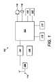
図1を参照すると、LTE通信システム内で動作する、通信デバイスの一例を構成する、ユーザ機器(user equipment、UE)デバイス100が処理リソース102を備え、処理リソース102は、本例では、セルラー通信端末のチップセットである。処理リソース102は、送信器回路104および受信器回路106を含む無線トランシーバ装置に結合され、送信器および受信器回路104、106は両方とも二重化装置108に結合されている。二重化装置108はアンテナ110に結合されている。 Referring to FIG. 1, a user equipment (UE)
UEデバイス100はまた、処理リソース102に各々結合された、揮発性メモリ、例えば、RAM112、および不揮発性メモリ、例えば、ROM114を有する。処理リソース102はまた、マイクロフォン116、スピーカ・ユニット118、キーパッド120、およびディスプレイ122に結合されている。当業者は、上述されたUEデバイス100のアーキテクチャが他の要素を備えることを理解するはずであるが、このような追加の要素は、説明の簡潔性および明瞭性を保つために本明細書において説明されなかった。
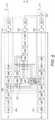
次に図2を参照すると、二重化装置の部分であることができる、信号絶縁制御装置が、直列-並列変換器ユニット202に動作可能に結合された変調器ユニット201を有する送信器回路104の主送信器チェーン200を含む。直列-並列変換器ユニット202は、第1の並列出力信号を提供するための複数の出力を含み、複数の出力は副搬送波マッパ・ユニット203の複数の入力に動作可能に結合されている。副搬送波マッパ203は、第2の並列出力信号を提供するための複数の出力を含み、第2の並列出力信号は、例えば、媒体アクセス制御方式に従って、入力シンボルを副搬送波周波数に対応付ける、その入力における並列信号の対応付けである。副搬送波マッパ203は並列入力よりも多数の並列出力を有することができ、対応付けられていない並列出力信号は、特定の副搬送波周波数における信号が存在しないよう、0に設定され、これにより、媒体アクセス制御方式によって必要とされ得るとおりに、スペクトル的に不連続な波形の送信を促進する。副搬送波マッパ・ユニット203の並列出力は、第1の並列-直列変換器ユニット206の対応する複数の入力に動作可能にそれぞれ結合された複数の出力を有する第1の逆高速フーリエ変換(Inverse Fast Fourier Transfer、IFFT)ユニット204に動作可能に結合され、第1の並列-直列変換器ユニット206の出力は第1のサイクリック・プレフィックス付加ユニット208に動作可能に結合されている。 Referring now to FIG. 2, a signal isolation controller, which can be part of a duplexer, is the
第1のサイクリック・プレフィックス付加ユニット208の出力は第1のデジタル-アナログ変換器(DAC)ユニット210に動作可能に結合され、第1のDACユニット210は主送信器無線ユニット212に動作可能に結合されている。送信器出力ノードを構成する、主送信器無線ユニット212の出力ノードはハイブリッド回路216の入力ノード214に動作可能に結合されている。ハイブリッド回路216のアンテナノード218はアンテナ110に動作可能に結合されている。ハイブリッド回路216の平衡化ノード220は可変インピーダンス222に動作可能に結合され、ハイブリッド回路216の出力ノード224は受信信号入力ノードに動作可能に結合され、受信信号入力ノードは、本例では、第1の入力および第2の入力を有する信号加算ユニット226であり、第1の入力はハイブリッド回路216の出力ノード224に動作可能に結合されている。The output of the first cyclic prefixing unit 208 is operatively coupled to a first digital-to-analog converter (DAC)
送信器回路104の補助送信器チェーン227への入力信号を提供するために、観念上のタッピング点228が副搬送波マッパ・ユニット203と第1のIFFTユニット204との間に設けられており、補助送信器チェーン227は送信器チェーン処理段階ユニットを含む。それゆえ、副搬送波マッパ・ユニット203の複数の出力は第1のスイッチング・ユニット229の複数の入力にも動作可能に結合され、第1のスイッチング・ユニット229の複数の第1の出力は第2の波形発生器230の複数の入力に動作可能に結合されている。副搬送波マッパ・ユニット203の複数の出力は係数プロセッサ252にも動作可能に結合されている。第1のスイッチング・ユニット229の複数の第2の出力は、適応フィルタユニット231、例えば、第2のスイッチング・ユニット232の複数の第1の入力に動作可能に結合された複数の出力を有する周波数領域イコライザ(Frequency Domain Equaliser、FDE)の複数の第1の入力に動作可能に結合されている。第2の波形発生器230の複数の出力は第2のスイッチング・ユニット232の複数の第2の入力に結合されている。第2の波形発生器230の複数の出力は係数プロセッサ252にも結合されている。第2のスイッチング・ユニット232の複数の出力は第2のIFFTユニット233の複数の入力に結合されている。第2のIFFTユニット233の複数の出力は第2の並列-直列変換器ユニット234の複数の入力に動作可能に結合され、第2の並列-直列変換器ユニット234は第2のサイクリック・プレフィックス付加ユニット236に動作可能に結合されている。第2のサイクリック・プレフィックス付加ユニット236の出力は第2のDACユニット238に動作可能に結合され、第2のDACユニット238は補助送信器無線ユニット240に動作可能に結合されている。補助送信器無線ユニット240の出力ノードは、受信信号入力ノードの、上述された、第2の入力に動作可能に結合されている。第2のIFFTユニット233、第2の並列-直列変換器ユニット234、第2のサイクリック・プレフィックス付加ユニット236、第2のDACユニット238、および/または補助送信器無線ユニット240のうちの1つまたは複数は、本例では、主送信器チェーン200によってサポートされた変調方式である、所望の変調方式に従って波形の処理を完了するように構成された補助送信器チェーン処理段階ユニットを構成する。無論、本例の補助送信器チェーン227は、説明の簡潔性のために簡略化された仕方で説明され、当業者は、送信器チェーン処理段階ユニットが、主送信器チェーン200内に存在する送信信号の発生をサポートする他の機能処理段階を含むことができることを理解するであろう。A
受信器回路106の受信器チェーン241は受信信号入力ノードを含み、受信信号入力ノードは受信器無線ユニット242の入力に動作可能に結合されている。受信器無線ユニット242の出力はアナログ-デジタル変換器(Analogue-to-Digital Converter、ADC)ユニット244の入力に動作可能に結合され、ADCユニット244の出力はサイクリック・プレフィックス除去ユニット246の入力に動作可能に結合されている。サイクリック・プレフィックス除去ユニット246の出力は、高速フーリエ変換(Fast Fourier Transform、FFT)ユニット250の複数の入力にそれぞれ動作可能に結合された複数の出力を有する第2の直列-並列変換器ユニット248の入力に動作可能に結合されている。FFTユニット250の複数の出力は、それぞれ、FDE係数プロセッサ252の複数の第1の入力に、およびそれぞれ、無線チャンネルFDEユニット254の複数の入力に動作可能に結合されている。FDE係数プロセッサ252は補間プロセッサ255を含む。しかし、当業者は、補間プロセッサ255が、実施の便益に従って、FDE係数プロセッサ252に対して別の仕方で配置され得るであろうことを理解するであろう。例えば、補間プロセッサ255はFDE係数プロセッサ252に動作可能に結合されていてもよい。FDE係数プロセッサ252の複数の出力は、それぞれ、適応フィルタユニット231の複数の第2の入力に動作可能に結合されている。FDE係数プロセッサ252の複数の第2の入力は第1のスイッチング・ユニット229の複数の第2の出力に動作可能に結合されている。
無線チャンネルFDEユニット254の複数の出力は、それぞれ、副搬送波デマッパ256に動作可能に結合され、副搬送波デマッパ256からの複数の出力は、第3の並列-直列変換器ユニット257に動作可能に結合され、第3の並列-直列変換器ユニット257の出力は復調器ユニット258に動作可能に結合されている。復調器ユニット258の出力は平衡化インピーダンス制御ユニット260の入力に動作可能に結合され、平衡化インピーダンス制御ユニット260の制御出力は可変インピーダンス222の制御入力に動作可能に結合されている。 A plurality of outputs of the radio
本例(および後続の例)では、主送信器チェーン200、補助送信器チェーン227、および受信器チェーン241が、共に、アクティブ干渉除去装置を構成することを理解されたい。 It should be appreciated that in this example (and subsequent examples),
図3を参照すると、主送信器チェーン200、ハイブリッド回路216、受信器チェーン241を通過する、およびそれらの間の経路をたどる波形によって経験される振幅および位相変化をモデル化するために、自己干渉伝達関数、例えば、周波数領域自己干渉伝達関数Δ(ω)が採用され得る。同様に、補助送信器チェーン227および受信器チェーン241を通過する、およびそれらの間の経路をたどる波形によって経験される振幅および位相変化をモデル化するために、除去伝達関数、例えば、周波数領域除去伝達関数Θ(ω)が採用され得る。 Referring to FIG. 3, to model the amplitude and phase changes experienced by waveforms that follow paths through and between
自己干渉伝達関数および除去伝達関数を定量化することによって、例えば、入力ノードからハイブリッド回路216の出力ノードに結合された、例えば、電磁結合された波形成分の除去を達成するために適応フィルタ231によって実施され得る、イコライザ関数Ξ(ω)を決定することが可能である。 By quantifying the self-interference transfer function and the cancellation transfer function, e.g. It is possible to determine the equalizer function Ξ(ω) that can be implemented.
この点について、自己干渉伝達関数および除去伝達関数が推定された場合には、主送信器チェーン200内で形成された送信波形STXに関する、結合された波形成分の除去のために、以下の式を用いることが可能である:
0=STX(ω)Δ(ω)+Ξ(ω)STX(ω)Θ(ω) (1)In this regard, if the self-interference transfer function and the cancellation transfer function are estimated, for the cancellation of the combined waveform components for the transmitted waveform STX formed within the
0=STX (ω)Δ(ω)+Ξ(ω)STX (ω)Θ(ω) (1)
この等式が(整理することによって)解かれ、以下の式を得ることができる:
自己干渉伝達関数Δ(ω)および除去伝達関数Θ(ω)が既知である場合には、イコライザ関数Ξ(ω)が算出され得る。 If the self-interference transfer function Δ(ω) and the cancellation transfer function Θ(ω) are known, the equalizer function Ξ(ω) can be calculated.
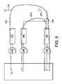
別の例(図4)では、図2の信号絶縁制御装置はハイブリッド回路216を採用せず、代わりに、アクティブ干渉除去装置は、主送信器無線ユニット212の出力ノードに動作可能に結合された第1のアンテナ270、および受信信号入力ノードを構成する、信号加算ユニット226の第1の入力に動作可能に結合された第2のアンテナ272を補われている。 In another example (FIG. 4), the signal isolation controller of FIG. Supplemented are a
本例では、図5を参照すると、主送信器チェーン200を通過する経路をたどり、第1のアンテナ270から第2のアンテナ272、および受信器チェーン241へ伝搬する波形によって経験される振幅および位相変化をモデル化するために、自己干渉伝達関数Δ(ω)が採用され得る。この点において、自己干渉伝達関数は主送信器チェーンおよび受信器チェーンのベースバンドおよび無線周波数処理段階を特徴付けることもできる。同様に、上述されたように、補助送信器チェーン227、受信器チェーン241、および相互接続回路機構を通過する経路をたどる波形によって経験される振幅および位相変化をモデル化するために、除去伝達関数Θ(ω)が採用され得る。この点において、除去伝達関数は補助送信器チェーンおよび受信器チェーンのベースバンドおよび無線周波数処理段階を特徴付けることもできる。 In this example, referring to FIG. 5, the amplitude and phase experienced by the waveform following a path through the
したがって、上式(等式(1))は、第1のアンテナ270から第2のアンテナ272に結合された波形を除去するために適用される。それゆえ、イコライザ関数Ξ(ω)を、図4の装置の適応フィルタユニット231による適用のために算出するために、等式(2)が採用され得る。 Therefore, the above equation (equation (1)) is applied to remove the waveform coupled from the
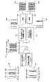
動作時(図6および図7)、アクティブ干渉除去装置が適応フィルタ231の係数を決定する必要があるときに、第1のスイッチング・ユニット229は、観念上のタッピング点228、例えば、直列-並列変換器ユニット202の複数の出力を第2の波形発生器230の複数の入力に結合するよう指示される。第2のスイッチング・ユニット232は、第2の波形発生器230の複数の出力を第2のIFFTユニット233の複数の入力に結合するよう指示される。その後、主送信器チェーン200は、変調器ユニット201を介して、直列-並列変換器202へ出力される第1の変調信号を発生する。第1の変調信号は直列-並列変換器202から副搬送波マッパ203へ並列に出力され、副搬送波マッパ203は、それぞれの複数の周波数点403における複数の周波数分離信号402を含む第1の波形400(図7)の周波数領域表現を発生する(ステップ300)ために、変調シンボルを副搬送波周波数に対応付ける。本例では、第1の変調信号および対応する副搬送波対応付けから発生される第1の波形400は、適応フィルタユニット231のためのイコライザ係数を算出することのみを目的として発生される。しかし、他の実施形態では、データを送信することを目的として発生される、すなわち、ペイロード・データに従って変調され、副搬送波対応付けが媒体アクセス制御方式に従って遂行された信号から発生される波形が代わりに用いられてもよい。並列形式の第1の波形400は、第1のIFFTユニット204による第1の波形400の異なる信号への逆フーリエ変換の適用、ならびにそれに続く、第1の直列-並列変換器ユニット206による直列形式への再変換、および送信に備えた、本例では、サイクリック・プレフィックス付加ユニット208によるサイクリック・プレフィックスの付加を含む、主送信器チェーン200の処理段階によって引き続き処理される。この点について、第1の波形400は、次に、図2の例に関しては、ハイブリッド回路216の入力ノード214への適用に先立って、送信無線ユニット212によってアップコンバートされ、増幅される前に、第1のADC210によってアナログ領域に変換される。第1の波形400のエネルギーの一部はアンテナ110に結合され、送信信号として放射される(ステップ302)。しかし、第1の波形400のエネルギーの一部はハイブリッド回路216の出力ノードに不必要に結合される。通常の状況下では、第1の波形400に基づくこの結合された波形は、アンテナ110によって正当に受信され、ハイブリッド回路216の出力端子224に受信器チェーン241による処理のために結合された信号に干渉するであろう、干渉信号を構成するであろう。 In operation (FIGS. 6 and 7), when the active interference cancellation device needs to determine the coefficients of the
無論、図4の例の文脈においては、ハイブリッド回路216は採用されておらず、代わりに、第1の波形400のエネルギーは第1のアンテナ270に、上述された送信信号としての放射のために結合される。しかし、送信信号のエネルギーの一部分は第2のアンテナ272によって不必要に受信される、またはそれに結合される。通常の状況下では、第1の波形400に基づくこの結合された波形は、第2のアンテナ272によって受信された求められる受信信号に干渉するであろう、干渉信号を構成するであろう。 Of course, in the context of the example of FIG. 4, the
しかし、本例では、変調器201、直列-並列変換器202、および副搬送波マッパ203は、交互の周波数点403における信号を含むよう第1の波形400を発生するように適切にプログラムされる。それゆえ、第1の波形400は、複数の第1の周波数点403の周りに配置された複数の第1の周波数分離信号402を含み、複数の第1の周波数点403は、対応する信号が存在しない交互の周波数点404によって分離されている。 However, in this example,
補助送信器チェーン227内において、第2の波形発生器230は、第1のスイッチング・ユニット229を介して第1の波形発生器201によって発生された第1の波形400を受信する(ステップ301)。次に、第2の波形発生器230は、信号によって占有されていない第1の波形400内の周波数点、すなわち、上述された対応する信号が存在しない第1の波形400の複数の第1の交互の周波数点404を決定するために、第1の波形400を分析する。次に、第2の波形発生器230(図2)は、占有されていない、複数の第1の交互の周波数点404に対応する第2のそれぞれの複数の周波数点410の周りに位置する複数の第2の周波数分離信号408を含むよう、第2の波形406を発生する(ステップ304)。第2の波形406の交互の周波数点412には、第1の波形400内の複数の第1の周波数点403において存在する信号が存在しない。その後、主送信器チェーン200に関する場合のように、第2の波形406の周波数分離信号を表現する並列信号は、サイクリック・プレフィックスが、複数の周波数分離信号を含む直列の第2の波形に付加される前に、第2の並列-直列変換器234によって並列形式から直列形式に変換される。 Within the
本例では、第2の波形406は、信号が配置される第2の波形406の交互の周波数点が、信号が送信のために配置される第1の波形400の周波数点とは異なるように発生される。したがって、第2の波形406が補助送信器チェーン227の出力から送信される(ステップ306)。それゆえ、第1の送信無線ユニット212の出力ノードにおいて、適応フィルタ231の係数を決定するために、第1の波形400は、第2の波形406と周波数が一致する信号を全く含まない。 In this example, the
本例では、第1の波形400には、第2の波形406の複数の第2の周波数分離信号408によって占有される周波数における適応フィルタ231のイコライザ係数の決定のために必要とされる信号が存在しない、例えば、意図的に存在しない。この点について、第2の波形406には、第1の波形400の複数の第1の周波数分離信号402によって占有される周波数における適応フィルタ231のイコライザ係数の決定のために必要とされる信号が存在しない、例えば、意図的に存在しない。例えば、複数の第1の周波数分離信号402および複数の第2の周波数分離信号408は周波数領域において交互配置されている。このような交互配置は必ずしも交互で規則的でなくてもよいことを理解されたい。 In this example, the
この点について、および別の実施形態では、第1の波形400は、ペイロード・データおよびシグナリング、ならびに通信ネットワークの媒体アクセス制御プロトコルに従ってデータを送信することを目的として発生される波形である。本例では、波形400は、通常動作時に通信デバイスから連続的に送信される一連の送信波形から選択され、これにより、選択された波形400は、信号が周波数点において存在しない、スペクトル的に不連続な波形となる。これは、通常動作の間にUEデバイス100から周期的に送られ得るシグナリングまたはリファレンス信号を包含する波形を選択することによって達成され得る。例えば、LTE通信システムでは、これは、例えば、サウンディングリファレンス信号(Sounding Reference Signal、SRS)を包含する送信波形を用いて達成され得る。第1の波形400内の信号の帯域幅および間隔は、選択された送信波形内に存在する送信信号によって決定される。選択された波形内の信号の帯域幅および間隔は、通信ネットワークにおける動作の間に、例えば、多重アクセス制御プロトコル、または周波数領域スケジューリング・プロトコル、ならびに/あるいはシグナリング・プロトコルに従って副搬送波マッパ203によって適用される副搬送波対応付けによって決定され得る。それゆえ、第1および第2の波形400、406の交互配置が周波数領域における繰り返しの規則的パターンに従う可能性は低い。それにもかかわらず、当業者は、この場合には、重畳波形414は、依然として上述されたように分離され得、それぞれの一貫した周波数間隔で生じない複数の第1の周波数点を有しながらも、部分的自己干渉伝達関数推定、および、それぞれの一貫した周波数間隔で生じない複数の第2の周波数点を有しながらも、部分的除去伝達関数推定の推定を可能にすることを認識するであろう。当業者はまた、複数の第1の周波数点403の周波数値にかかわらず、適切な補間技法314、316が自己干渉伝達関数416の部分推定に適用され得、複数の第2の周波数点410の周波数値にかかわらず、適切な補間技法が除去伝達関数418の部分推定に適用され得ることを認識するであろう。 In this regard, and in another embodiment, the
いずれにせよ、どちらの実施形態に関しても、受信信号入力ノードにおいて、第1の波形400および第2の波形406が受信され(ステップ308)、合成波形を構成する、第1および第2の波形400、406の両方の重畳414が受信信号入力ノードの出力において出力される。次に、波形414の重畳は受信器チェーン241によって処理される。この点において、受信器無線ユニット242が波形414の重畳をベースバンドにダウン・コンバートし、受信されたベースバンド信号はADCユニット244によってデジタル領域に変換される。その後、サイクリック・プレフィックス除去ユニット246がサイクリック・プレフィックスを、ADCユニット244によって出力されたデジタル信号から除去する。次に、第2の直列-並列変換器ユニット248が、サイクリック・プレフィックスを取り除かれたデジタル信号を複数の並列デジタル受信信号に変換し、各出力は(第1および第2の波形400、406から導出された)重畳波形414の信号の周波数に対応する。In any event, for either embodiment, at the receive signal inputnode , the
直列-並列変換器ユニット248の複数の出力における信号は、信号を時間領域から周波数領域へ変換するために重畳波形414の複数の信号に対してフーリエ変換を遂行する、FFTユニット250の複数の入力にそれぞれ適用される。FFTユニット250の出力は、第1および第2の波形400、406の複数の信号を分析する、係数プロセッサ・ユニット252によって受信される。 The signals at the outputs of serial-to-
具体的には、係数プロセッサ・ユニット252は、その入力における、副搬送波マッパ203および波形発生器230の出力によってそれぞれ提供されたとおりの、送信波形400、406を観察し、複数の第1の周波数点403および複数の第2の周波数点410を決定する。次に、係数プロセッサ・ユニット252は、第1の波形400の複数の第1の周波数分離信号402が重畳波形414の複数の第1の周波数点403に配置され、第2の波形406の複数の第2の周波数分離信号408が重畳波形414の複数の第2の周波数点410に配置されていることの知識を用いて、実施の基本設定に依存して、交互の周波数点の第1のセットおよび交互の周波数点の第2のセットを選択することによって複数の第1の周波数分離信号402および複数の第2の周波数分離信号408を選択または抽出し、ここで、交互の周波数点の第2のセットは交互の周波数点の第1のセットと交互配置されている。結合された第1の波形400に関する重畳波形414の部分として受信された複数の第1の周波数分離信号402、および第1の波形400内で送信されたとおりの複数の第1の試験信号402を用いて、係数プロセッサ・ユニット252は自己干渉伝達関数416の部分推定を発生し(ステップ310)、同様に、重畳波形414内で受信されたとおりの複数の第2の周波数分離信号408、および第2の波形406内で送信されたとおりの複数の第2の試験信号408を用いて、係数プロセッサ・ユニット252は除去伝達関数418の部分推定を発生する(ステップ312)。受信信号入力ノードに結合されたそれぞれの第1および複数の第2の信号402、408には、交互の周波数点における信号がそれぞれ存在しないため、推定は部分的である。自己干渉伝達関数416の部分推定に関して、推定は、推定された係数の間の交互の係数を欠いている。したがって、補間プロセッサは、本例では補間によって、自己干渉伝達関数の部分推定に存在しない係数、例えば、それぞれ、第1の波形内に存在する隣接する周波数の間にある周波数に対応する係数を算出する(ステップ314)、例えば、推定する。この点について、これは、それぞれ、第1の波形内の隣接する周波数分離信号の間にある周波数に関するものであることができる。このように、自己干渉伝達関数の完全推定420が得られる(図7)。同様に、除去伝達関数418の部分推定に関して、推定は、推定された係数の間の交互の係数を欠いている。したがって、補間プロセッサは、本例では補間によって、除去伝達関数の部分推定に存在しない係数、例えば、第2の波形内に存在する周波数に対応する係数を算出する(ステップ316)、例えば、推定する。この点について、これは、それぞれ、第2の波形内の隣接する周波数分離信号の間にある周波数に関するものであることができる。このように、除去伝達関数の完全推定422が得られる(図7)。Specifically, the
自己干渉伝達関数420および除去伝達関数422の完全推定の発生に続き、補間プロセッサ255の助けを借りて、完成された推定420、422が係数プロセッサ252へ通信され、係数プロセッサ252は上述の等式(2)を利用し、本例では第2の周波数領域伝達関数による第1の周波数領域伝達関数の負号除算である、適応フィルタ231の係数を算出する(ステップ318)。次に、算出された係数は適応フィルタ231に適用され(ステップ320)、これにより、受信信号入力ノードにおいて、除去信号が、例えば、入力ノード214からハイブリッド回路216の出力ノード224への第1の波形の漏れの結果として、受信信号入力ノードにおいて受信されたとおりの送信信号内に存在する不必要な信号成分を除去するよう、補助送信器チェーン227によって発生された除去信号を「成形する」ように適応フィルタ231を設定する。Following generation of full estimates of the self-
適応フィルタ231の初期プログラミングの完了に続き、第1のスイッチング・ユニット229が、観念上のタッピング点228、例えば、第1の直列-並列変換器ユニット202の複数の出力を適応フィルタユニット231の複数の第1の入力および係数プロセッサ252の複数の第2の入力に結合するよう指示される。第2のスイッチング・ユニット232もまた、適応フィルタユニット231の複数の出力を第2のIFFTユニット233の複数の入力に結合するよう指示される。 Following completion of the initial programming of
その後、アクティブ干渉除去装置が送信データの通信のための波形を主送信器チェーン200内で発生し、補助送信器チェーン227が、アンテナおよび受信器チェーン241を介して受信された受信信号内に存在する不必要な信号成分を除去するための除去信号を発生し、任意の好適な技法に従って、例えば、無線通信規格、例えば、LTEに従って受信信号を復号する。 The active interference canceller then generates waveforms for communication of transmit data within the
この点について、送信データの通信のために発生された波形に関連する主送信器チェーン200内の一時的信号が観念上のタッピング点228を介して補助送信器チェーン227内へタッピングされ、以上において決定された算出されたイコライザ係数を適用する適応フィルタ231によって変更される。補助送信器チェーン227は、変更されたタッピングされた一時的信号を完全に処理し、送信器出力ノード(本例では、主送信器無線ユニット212の出力)から受信信号入力ノードに結合されたとおりの送信信号を除去する、受信信号入力ノードにおける除去信号をもたらす。除去信号は、受信信号入力ノードにおいて受信された送信信号の逆位相推定である。本例では、したがって、除去信号は、受信信号入力ノードに結合されたとおりの送信信号に相殺的に干渉する。In this regard, the transient signals within the
別の例では、共通波形、例えば、第1の波形および第2の波形400、406の両方のための共通パイロット波形を採用することによって達成される、数学演算に対する単純化が利用され得る。この点について、自己干渉伝達関数Δ(ω)は次式によって与えられることができる:
ここで、SRxTx(ω)は、第1の波形400に関する受信器チェーン241の出力において発生される信号であり、SP1は、第1の波形400を構成し、複数の第1の副搬送波を含む第1のパイロット信号である。以上の等式(4)は、補助送信器チェーン227が第2の波形406を送信していないことを仮定する。where SRxTx (ω) is the signal generated at the output of the
除去伝達関数Θ(ω)は同様の仕方で算出される。この点において、除去伝達関数Θ(ω)は以下の式によって与えられることができる:
ここで、SRxTx(ω)は、第2の波形406に関する受信器チェーン241の出力において発生される信号であり、SP2は、第2の波形406を構成し、複数の第2の副搬送波を含む第2のパイロット信号である。以上の等式(3)は、主送信器チェーン200が第1の波形400を送信していないことを仮定する。where SRxTx (ω) is the signal generated at the output of the
等式(3)および(4)を、以前に導出された等式(2)に代入することで、次式を得る:
しかし、共通パイロットSP(ω)が第1および第2の波形400、406に関して採用される場合には:
この単純化を用いると、周波数領域イコライザ係数の推定は次式に単純化する:
このようなアプローチは、遂行されるべき算出を副搬送波ごとに単一の除算に低減することによって、係数プロセッサ252の計算オーバヘッドを低減する。記憶オーバヘッドもまた低減される。 Such an approach reduces the computational overhead of
この点について、副搬送波を含む第1および第2の波形の文脈においては、周波数領域イコライザ係数の推定は次式として表され得る:
ここで、kは副搬送波番号である。 where k is the subcarrier number.
共通の第1および第2の波形400、406は、各波形が、異なる周波数点における信号を含み、同時に送信されるにもかかわらず、図2の第1の装置および図4の第2の装置に関して利用され得、第1の波形400および第2の波形406は両方とも、共通の基礎をなす連続周波数関数SP(ω)の離散化を含むが、離散化は異なる周波数点において遂行され得る。Common first and
以上において説明された本発明の例示的な実施形態は、限定ではなく、例示であると考えられる。上述の実施形態に対する様々な変更が、本発明の趣旨および範囲から逸脱することなく行われ得る。 The exemplary embodiments of the invention described above are to be considered illustrative, not limiting. Various changes to the above-described embodiments may be made without departing from the spirit and scope of the invention.
当業者は、上述の実装形態は、添付の請求項の範囲内で考え得る様々な実装形態の単なる例にすぎないことを理解するべきである。実際に、例えば、第2の波形発生器230は、第1のスイッチング・ユニット229を用いて適応フィルタユニット231を迂回する代わりに、適応フィルタユニット231の複数の第1の入力に結合されてもよい。このような例では、第1のスイッチング・ユニット229は、観念上のタッピング点228を適応フィルタユニット231に結合することを優先して、第2の波形発生器230を適応フィルタユニット231に選択的に結合するために利用されてもよく、第2の波形発生器230が適応フィルタユニット231に結合されるときには、適応フィルタユニット231の係数はユニティ・ゲインに設定されてもよい。 Those skilled in the art should understand that the implementations described above are merely examples of the various possible implementations within the scope of the appended claims. Indeed, for example, the
本明細書において説明されるハイブリッド回路216に関して、当業者は、任意の好適な構成が採用され得ることを理解するべきである。例えば、上述の実施形態では、変成器ハイブリッド分岐が説明された。別の実施形態では、直角位相(quadrature)ハイブリッド分岐が採用されたが、他の変形例、例えば、180°変成器ハイブリッド分岐も用いられ得るであろう。他の好適な種類のハイブリッド分岐、例えば、導波管ハイブリッド分岐が採用されることも可能である。 With respect to the
上述の実施形態のシステムおよび方法は、上述された構造構成要素およびユーザ対話に加えて、コンピュータ・システムにおいて(具体的には、コンピュータ・ハードウェアもしくはコンピュータ・ソフトウェアにおいて)、または特定的に製造された、もしくは適応させられた集積回路において実施されてもよい。上述の実施形態の方法は、コンピュータ・プログラムとして、またはコンピュータまたは他のプロセッサ上で実行されたときに、上述された方法を遂行するように構成されたコンピュータ・プログラムを保持する、コンピュータ・プログラム製品もしくはコンピュータ可読媒体として提供されてもよい。 The systems and methods of the above-described embodiments, in addition to the structural components and user interactions described above, may be implemented in computer systems (specifically, in computer hardware or computer software) or specifically manufactured in It may also be implemented in a separate or adapted integrated circuit. The method of the above-described embodiments is a computer program product or computer program product carrying a computer program configured to perform the above-described method when run on a computer or other processor. Alternatively, it may be provided as a computer readable medium.
用語「コンピュータ可読媒体」は、限定するものではないが、コンピュータまたはコンピュータ・システムによって直接読み取られ、アクセスされ得る任意の媒体(medium)または媒体群(media)を含む。媒体(media)は、限定するものではないが、フロッピー・ディスク、ハード・ディスク記憶媒体、および磁気テープなどの磁気記憶媒体、光ディスクまたはCD-ROMなどの光学記憶媒体、RAM、ROM、およびフラッシュ・メモリを含む、メモリなどの電気記憶媒体、ならびに磁気/光学記憶媒体などの上述のもののハイブリッドおよび組合せを含むことができる。 The term "computer-readable medium" includes, but is not limited to, any medium or media that can be read and accessed directly by a computer or computer system. The media include, but are not limited to, magnetic storage media such as floppy disks, hard disk storage media, and magnetic tapes; optical storage media, such as optical discs or CD-ROMs; RAM, ROM, and flash media; It can include electrical storage media such as memory, including memory, and hybrids and combinations of the above such as magnetic/optical storage media.
Claims (13)
Translated fromJapanese受信信号入力ノードを含む受信器チェーンと、
送信器チェーンタップノードおよび送信器出力ノードを含む送信器チェーンと、
前記送信器チェーンタップノードに動作可能に結合された補助チェーン入力ノードを有する補助送信器チェーンであって、前記補助送信器チェーンが、適応フィルタユニットおよび除去信号出力を含み、前記除去信号出力が、前記受信器チェーンの前記受信信号入力ノードに動作可能に結合されている、補助送信器チェーンと、
補間プロセッサと、
を備え、
前記適応フィルタユニットが係数処理ユニットおよび適応フィルタを含み、前記係数処理ユニットが前記受信器チェーンおよび前記適応フィルタに動作可能に結合され、
前記補間プロセッサが、前記係数処理ユニットと協働するように構成され、
前記送信器チェーンが、使用時に、複数の第1の周波数分離信号を含む第1の波形を発生するように構成され、
前記送信器チェーンと実質的に同時に、前記補助送信器チェーンが、複数の第2の周波数分離信号を含む第2の波形を発生し、前記第2の波形を前記受信信号入力ノードにおいて適用するように構成され、
前記受信器チェーンが、前記送信器チェーンの前記出力ノードから前記受信器チェーンの前記受信信号入力ノードに結合された波形、および前記補助送信器チェーンからの前記第2の波形を含む合成波形を受信するように構成され、
前記第1の波形が、前記第2の波形の前記複数の第2の周波数分離信号と周波数が一致する前記適応フィルタのイコライザ係数の決定のために必要とされる信号を全く含まず、
前記第1の波形には、前記第2の波形の前記複数の第2の周波数分離信号によって占有される周波数における前記適応フィルタの前記イコライザ係数の決定のために必要とされる信号が存在せず、
前記第2の波形には、前記第1の波形の前記複数の第1の周波数分離信号によって占有される周波数における前記適応フィルタの前記イコライザ係数の決定のために必要とされる信号が存在せず、
前記複数の第1の周波数分離信号および前記複数の第2の周波数分離信号が周波数領域において交互配置され、
前記適応フィルタユニットが、前記送信器チェーンおよび前記受信器チェーン内およびそれらの間で前記第1の波形によって経験される変化をモデル化する周波数領域自己干渉伝達関数の係数を推定するように構成され、
前記適応フィルタが、前記補助送信器チェーンおよび前記受信器チェーン内およびそれらの間で前記第2の波形によって経験される変化をモデル化する周波数領域除去伝達関数の係数を推定するように構成され、
前記補間プロセッサが、前記第1の波形に存在しない周波数に関する前記周波数領域自己干渉伝達関数の係数、および前記第2の波形に存在しない周波数に関する前記周波数領域除去伝達関数の係数を推定するように構成され、
前記自己干渉伝達関数が、前記送信器チェーン、前記受信器チェーンによって遂行される前記第1の波形の処理、および前記送信器チェーンから前記受信器チェーンへの前記第1の波形の結合をモデル化し、
前記除去伝達関数が、前記送信器チェーン、前記受信器チェーン、および相互接続回路によって遂行される前記第2の波形の処理をモデル化し、
前記補間プロセッサが、それぞれ、前記第1の波形内に存在する隣接する周波数の間の周波数に関する前記周波数領域自己干渉伝達関数の前記係数を推定するように構成され、
前記補間プロセッサが、それぞれ、前記第2の波形内に存在する隣接する周波数の間の周波数に関する前記周波数領域除去伝達関数の前記係数を推定するように構成され、
前記係数処理ユニットが、前記推定された周波数領域自己干渉伝達関数および前記推定された周波数領域除去伝達関数を前記補間プロセッサから受信するように構成され、前記係数処理ユニットが、前記推定された周波数領域自己干渉伝達関数および前記推定された周波数領域除去伝達関数を用いて前記適応フィルタのための前記イコライザ係数を算出するように構成されている、アクティブ干渉除去装置。 An active interference cancellation device for controlling the duplex behavior of transmitted and received signals, said device comprising:
a receiver chain including a received signal input node;
a transmitter chain including a transmitter chain tap node and a transmitter output node;
an auxiliary transmitter chain having an auxiliary chain input node operatively coupled to said transmitter chain tap node, said auxiliary transmitter chain including an adaptive filter unit and a cancellation signal output, said cancellation signal output comprising: an auxiliary transmitter chain operably coupled to the received signal input node of the receiver chain;
an interpolation processor;
with
said adaptive filter unit comprising a coefficient processing unit and an adaptive filter, said coefficient processing unit operatively coupled to said receiver chain and said adaptive filter;
the interpolation processor is configured to cooperate with the coefficient processing unit;
the transmitter chain, in use, is configured to generate a first waveform comprising a plurality of first frequency separated signals;
Substantially simultaneously with the transmitter chain, the auxiliary transmitter chain generates a second waveform comprising a plurality of second frequency separated signals and applies the second waveform at the received signal input node. configured to
The receiver chain receives a composite waveform comprising a waveform coupled from the output node of the transmitter chain to the received signal input node of the receiver chain and the second waveform from the auxiliary transmitter chain. is configured to
wherein said first waveform contains all the signals needed for determination of equalizer coefficients of said adaptive filter matched in frequency with said plurality of second frequency separated signals of said second waveform;figure,
The first waveform is free of signals needed for determination of the equalizer coefficients of the adaptive filter at frequencies occupied by the plurality of second frequency separated signals of the second waveform. ,
The second waveform is free of signals needed for determination of the equalizer coefficients of the adaptive filter at frequencies occupied by the plurality of first frequency separated signals of the first waveform. ,
the plurality of first frequency-separated signals and the plurality of second frequency-separated signals are interleaved in the frequency domain;
The adaptive filter unit is configured to estimate coefficients of a frequency domain self-interference transfer function that models changes experienced by the first waveform within and between the transmitter chain and the receiver chain. ,
the adaptive filter is configured to estimate coefficients of a frequency domain rejection transfer function that models changes experienced by the second waveform in and between the auxiliary transmitter chain and the receiver chain;
The interpolation processor is configured to estimate coefficients of the frequency-domain self-interference transfer function for frequencies not present in the first waveform and coefficients of the frequency-domain rejection transfer function for frequencies not present in the second waveform. is,
The self-interference transfer function models processing of the first waveform performed by the transmitter chain, the receiver chain, and coupling of the first waveform from the transmitter chain to the receiver chain. ,
the cancellation transfer function models the processing of the second waveform performed by the transmitter chain, the receiver chain, and interconnect circuitry;
the interpolation processors are each configured to estimate the coefficients of the frequency domain self-interference transfer function for frequencies between adjacent frequencies present in the first waveform;
the interpolation processors are each configured to estimate the coefficients of the frequency domain rejection transfer function for frequencies between adjacent frequencies present in the second waveform;
The coefficient processing unit is configured to receive the estimated frequency-domain self-interference transfer function and the estimated frequency-domain cancellation transfer function from the interpolation processor, wherein the coefficient processing unit receives the estimated frequency-domain configured to calculate the equalizer coefficients for the adaptive filter using the self-interference transfer function and the estimated frequency domain rejection transfer function;Active interference canceller.
入力ノード、出力ノード、アンテナに結合するためのアンテナノード、および平衡ノードを含むハイブリッド回路をさらに備え、
前記受信信号入力ノードが前記ハイブリッド回路の前記出力ノードに動作可能に結合され、
前記送信器チェーン出力ノードが前記ハイブリッド回路の前記入力ノードに動作可能に結合され、
前記送信器チェーンから前記受信器チェーンに結合された前記波形が前記ハイブリッド回路によってその前記入力ノードからその前記出力ノードへ漏洩させられる、信号絶縁制御装置。A signal isolation control device comprising an active interference cancellation device according to any one of claims 1 to6 , said device comprising:
further comprising a hybrid circuit including an input node, an output node, an antenna node for coupling to the antenna, and a balance node;
the received signal input node is operatively coupled to the output node of the hybrid circuit;
the transmitter chain output node is operatively coupled to the input node of the hybrid circuit;
A signal isolation controller wherein the waveform coupled from the transmitter chain to the receiver chain is leaked by the hybrid circuit from its input node to its output node.
前記平衡化インピーダンスコントローラの出力に動作可能に結合された制御入力を有する可変インピーダンスであって、前記可変インピーダンスがまた、前記ハイブリッド回路の前記平衡ノードに動作可能に結合されている、可変インピーダンスと、
をさらに備える、請求項7に記載の装置。a balanced impedance controller having an input operably coupled to the output of the receiver chain;
a variable impedance having a control input operably coupled to the output of the balanced impedance controller, the variable impedance also operably coupled to the balanced node of the hybrid circuit;
8. The apparatus of claim7 , further comprising:
前記送信器出力ノードに動作可能に結合された送信アンテナと、
前記受信信号入力ノードに動作可能に結合された受信アンテナと、
をさらに備える信号絶縁制御装置。A signal isolation control device comprising an active interference cancellation device according to any one of claims 1 to6 , said device comprising:
a transmit antenna operably coupled to the transmitter output node;
a receive antenna operably coupled to the received signal input node;
A signal isolation controller further comprising:
受信信号入力ノードを含む受信器チェーンを提供することと、
送信器チェーンタップノードおよび送信器出力ノードを含む送信器チェーンを提供することと、
前記送信器チェーンタップノードに動作可能に結合された補助チェーン入力ノードを有する補助送信器チェーンであって、前記補助送信器チェーンが、適応フィルタユニットおよび除去信号出力を含み、前記除去信号出力が、前記受信器チェーンの前記受信信号入力ノードに動作可能に結合されている補助送信器チェーンを提供することと、
前記適応フィルタユニットが係数処理ユニットおよび適応フィルタを含み、前記係数処理ユニットを前記受信器チェーンおよび前記適応フィルタに動作可能に結合することと、
前記係数処理ユニットと協働する補間プロセッサを提供することと、
前記送信器チェーンが、使用時に、複数の第1の周波数分離信号を含む第1の波形を送信することと、
前記補助送信器チェーンが、複数の第2の周波数分離信号を含む第2の波形を前記送信器チェーンと実質的に同時に発生することと、
前記第2の波形を前記受信信号入力ノードにおいて適用することと、
前記受信器チェーンが、前記送信器チェーンの前記出力ノードから前記受信器チェーンの前記受信信号入力ノードに結合された波形、および前記補助送信器チェーンからの前記第2の波形を含む合成波形を受信することと、
前記第1の波形が、前記第2の波形の前記複数の第2の周波数分離信号と周波数が一致する前記適応フィルタのイコライザ係数の決定のために必要とされる信号を全く含まないことと、
前記第1の波形には、前記第2の波形の前記複数の第2の周波数分離信号によって占有される周波数における前記適応フィルタの前記イコライザ係数の決定のために必要とされる信号が存在しないことと、
前記第2の波形には、前記第1の波形の前記複数の第1の周波数分離信号によって占有される周波数における前記適応フィルタの前記イコライザ係数の決定のために必要とされる信号が存在しないことと、
前記複数の第1の周波数分離信号および前記複数の第2の周波数分離信号を周波数領域において交互配置することと、
前記適応フィルタユニットが、前記送信器チェーンおよび前記受信器チェーン内およびそれらの間で前記第1の波形によって経験される変化をモデル化する周波数領域自己干渉伝達関数の係数を推定することと、
前記適応フィルタが、前記補助送信器チェーンおよび前記受信器チェーン内およびそれらの間で前記第2の波形によって経験される変化をモデル化する周波数領域除去伝達関数の係数を推定することと、
前記補間プロセッサが、前記第1の波形に存在しない周波数に関する前記周波数領域自己干渉伝達関数の係数、および前記第2の波形に存在しない周波数に関する前記周波数領域除去伝達関数の係数を推定することと、
前記自己干渉伝達関数が、前記送信器チェーン、前記受信器チェーンによって遂行される前記第1の波形の処理、および前記送信器チェーンから前記受信器チェーンへの前記第1の波形の結合をモデル化することと、
前記除去伝達関数が、前記送信器チェーン、前記受信器チェーン、および相互接続回路によって遂行される前記第2の波形の処理をモデル化することと、
前記補間プロセッサが、それぞれ、前記第1の波形内に存在する隣接する周波数の間の周波数に関する前記周波数領域自己干渉伝達関数の前記係数を推定することと、
前記補間プロセッサが、それぞれ、前記第2の波形内に存在する隣接する周波数の間の周波数に関する前記周波数領域除去伝達関数の前記係数を推定することと、
前記係数処理ユニットが、前記推定された周波数領域自己干渉伝達関数および前記推定された周波数領域除去伝達関数を前記補間プロセッサから受信し、前記係数処理ユニットが、前記推定された周波数領域自己干渉伝達関数および前記推定された周波数領域除去伝達関数を用いて前記適応フィルタのための前記イコライザ係数を算出することと、
を含む方法。 A method of actively canceling interference for signal duplex communication, the method comprising:
Includes receive signal input nodeproviding a receiver chain;
Includes transmitter chain tap node and transmitter output nodeproviding a transmitter chain;
an auxiliary transmitter chain having an auxiliary chain input node operatively coupled to said transmitter chain tap node, said auxiliary transmitter chain comprising:adaptive filter unitand rejection signal outputincludesand said cancellation signal output is operatively coupled to said received signal input node of said receiver chainproviding an auxiliary transmitter chain;
said adaptive filter unit comprising a coefficient processing unit and an adaptive filter, operably coupling said coefficient processing unit to said receiver chain and said adaptive filter;
providing an interpolation processor cooperating with the coefficient processing unit;
the transmitter chain comprising:When usingtransmitting a first waveform comprising a plurality of first frequency separated signals;
the auxiliary transmitter chain transmitting a second waveform comprising a plurality of second frequency separated signals;said transmitter chain andoccurring substantially simultaneously; and
said receiving said second waveformsignal input nodeto apply in,
Previousa receiver chain comprising the transmitter chainThe output node offrom the receiver chainthe received signal input node ofreceiving a composite waveform including the waveform coupled to and the second waveform from the auxiliary transmitter chain;
said first waveform does not contain any signals needed for determination of equalizer coefficients of said adaptive filter that match in frequency with said plurality of second frequency separated signals of said second waveform;
the absence of signals in the first waveform needed for determination of the equalizer coefficients of the adaptive filter at frequencies occupied by the plurality of second frequency separated signals of the second waveform; When,
the absence of signals in the second waveform needed for determination of the equalizer coefficients of the adaptive filter at frequencies occupied by the plurality of first frequency separated signals of the first waveform; When,
interleaving the plurality of first frequency-separated signals and the plurality of second frequency-separated signals in the frequency domain;
the adaptive filter unit estimating coefficients of a frequency domain self-interference transfer function that models changes experienced by the first waveform in and between the transmitter chain and the receiver chain;
the adaptive filter estimating coefficients of a frequency domain rejection transfer function that models changes experienced by the second waveform in and between the auxiliary transmitter chain and the receiver chain;
the interpolation processor estimating coefficients of the frequency-domain self-interference transfer function for frequencies not present in the first waveform and coefficients of the frequency-domain rejection transfer function for frequencies not present in the second waveform;
The self-interference transfer function models the processing of the first waveform performed by the transmitter chain, the receiver chain, and the coupling of the first waveform from the transmitter chain to the receiver chain. and
the cancellation transfer function models the processing of the second waveform performed by the transmitter chain, the receiver chain, and interconnect circuitry;
each of the interpolation processors estimating the coefficients of the frequency domain self-interference transfer function for frequencies between adjacent frequencies present in the first waveform;
each of the interpolation processors estimating the coefficients of the frequency domain rejection transfer function for frequencies between adjacent frequencies present in the second waveform;
The coefficient processing unit receives the estimated frequency-domain self-interference transfer function and the estimated frequency-domain rejection transfer function from the interpolation processor, and the coefficient processing unit receives the estimated frequency-domain self-interference transfer function. and calculating the equalizer coefficients for the adaptive filter using the estimated frequency domain rejection transfer function;
method including.
Applications Claiming Priority (1)
| Application Number | Priority Date | Filing Date | Title |
|---|---|---|---|
| PCT/EP2018/058214WO2019185157A1 (en) | 2018-03-29 | 2018-03-29 | Active interference cancellation apparatus, signal isolation control apparatus and method of actively cancelling interference |
Publications (2)
| Publication Number | Publication Date |
|---|---|
| JP2021525013A JP2021525013A (en) | 2021-09-16 |
| JP7174771B2true JP7174771B2 (en) | 2022-11-17 |
Family
ID=61899260
Family Applications (1)
| Application Number | Title | Priority Date | Filing Date |
|---|---|---|---|
| JP2020552292AActiveJP7174771B2 (en) | 2018-03-29 | 2018-03-29 | Active interference cancellation device, signal isolation control device and method for actively canceling interference |
Country Status (5)
| Country | Link |
|---|---|
| US (1) | US11374613B2 (en) |
| EP (1) | EP3776876B1 (en) |
| JP (1) | JP7174771B2 (en) |
| CN (1) | CN112262533B (en) |
| WO (1) | WO2019185157A1 (en) |
Families Citing this family (5)
| Publication number | Priority date | Publication date | Assignee | Title |
|---|---|---|---|---|
| US11831587B2 (en)* | 2020-07-07 | 2023-11-28 | Parallel Wireless, Inc. | 6G ORAN star array with simultaneous transmit and receive |
| JP7725255B2 (en)* | 2021-06-24 | 2025-08-19 | 東芝テック株式会社 | communication equipment |
| US12176964B2 (en)* | 2021-12-27 | 2024-12-24 | Rohde & Schwawrz GmbH & Co. KG | Method and system for determining a transfer function of an RX path |
| US20230397031A1 (en)* | 2022-06-07 | 2023-12-07 | Dish Wireless L.L.C. | Coverage and load based smart mobility |
| US11611364B1 (en)* | 2022-10-20 | 2023-03-21 | Deco Integration Technology Co., Limited | Millimeter-wave isolation device |
Citations (7)
| Publication number | Priority date | Publication date | Assignee | Title |
|---|---|---|---|---|
| JP2002538712A (en) | 1999-03-03 | 2002-11-12 | シーメンス アクチエンゲゼルシヤフト | Frequency multiplex transceiver and crosstalk cancellation method |
| US20130155913A1 (en) | 2011-12-14 | 2013-06-20 | Redline Communications Inc. | Single channel full duplex wireless communication |
| US20130294295A1 (en) | 2012-05-02 | 2013-11-07 | Texas Instruments Incorporated | Transmit signal cancelation apparatus and methods |
| US20160043767A1 (en) | 2013-03-14 | 2016-02-11 | Telefonaktiebolaget L M Ericsson (Publ) | Transmitter Receiver Leakage Reduction In A Full Duplex System Without The Use Of A Duplexer |
| CN105721017A (en) | 2014-12-19 | 2016-06-29 | 英特尔公司 | Device and method for self-interference cancellation |
| JP2016522626A (en) | 2013-05-16 | 2016-07-28 | ゼットティーイー コーポレイション | Method and apparatus for canceling signal in wireless communication system |
| WO2016128032A1 (en) | 2015-02-10 | 2016-08-18 | U-Blox Ag | Signal isolation control apparatus and method of controlling a hybrid junction |
Family Cites Families (7)
| Publication number | Priority date | Publication date | Assignee | Title |
|---|---|---|---|---|
| CN101083472B (en)* | 2006-05-30 | 2011-07-20 | 富士通株式会社 | System and method for adjusting compensation applied to a signal |
| US8300561B2 (en)* | 2008-12-30 | 2012-10-30 | Texas Instruments Incorporated | Methods and apparatus for canceling distortion in full-duplex transceivers |
| CN101656562B (en)* | 2009-09-22 | 2012-07-18 | 武汉虹信通信技术有限责任公司 | Device and method for realizing elimination of self-excitation interference of repeater |
| US9318094B2 (en)* | 2011-06-03 | 2016-04-19 | Cirrus Logic, Inc. | Adaptive noise canceling architecture for a personal audio device |
| US9831898B2 (en)* | 2013-03-13 | 2017-11-28 | Analog Devices Global | Radio frequency transmitter noise cancellation |
| EP2903170B1 (en)* | 2014-02-04 | 2020-01-08 | U-blox AG | Duplexing apparatus, wireless devices and related methods |
| CN105187092B (en)* | 2015-08-10 | 2018-01-16 | 广东欧珀移动通信有限公司 | A kind of method and apparatus for the interference signal for reducing mobile communication |
- 2018
- 2018-03-29JPJP2020552292Apatent/JP7174771B2/enactiveActive
- 2018-03-29USUS17/042,397patent/US11374613B2/enactiveActive
- 2018-03-29WOPCT/EP2018/058214patent/WO2019185157A1/ennot_activeCeased
- 2018-03-29EPEP18715637.7Apatent/EP3776876B1/enactiveActive
- 2018-03-29CNCN201880092012.8Apatent/CN112262533B/enactiveActive
Patent Citations (7)
| Publication number | Priority date | Publication date | Assignee | Title |
|---|---|---|---|---|
| JP2002538712A (en) | 1999-03-03 | 2002-11-12 | シーメンス アクチエンゲゼルシヤフト | Frequency multiplex transceiver and crosstalk cancellation method |
| US20130155913A1 (en) | 2011-12-14 | 2013-06-20 | Redline Communications Inc. | Single channel full duplex wireless communication |
| US20130294295A1 (en) | 2012-05-02 | 2013-11-07 | Texas Instruments Incorporated | Transmit signal cancelation apparatus and methods |
| US20160043767A1 (en) | 2013-03-14 | 2016-02-11 | Telefonaktiebolaget L M Ericsson (Publ) | Transmitter Receiver Leakage Reduction In A Full Duplex System Without The Use Of A Duplexer |
| JP2016522626A (en) | 2013-05-16 | 2016-07-28 | ゼットティーイー コーポレイション | Method and apparatus for canceling signal in wireless communication system |
| CN105721017A (en) | 2014-12-19 | 2016-06-29 | 英特尔公司 | Device and method for self-interference cancellation |
| WO2016128032A1 (en) | 2015-02-10 | 2016-08-18 | U-Blox Ag | Signal isolation control apparatus and method of controlling a hybrid junction |
Also Published As
| Publication number | Publication date |
|---|---|
| CN112262533A (en) | 2021-01-22 |
| EP3776876A1 (en) | 2021-02-17 |
| JP2021525013A (en) | 2021-09-16 |
| US11374613B2 (en) | 2022-06-28 |
| US20210058110A1 (en) | 2021-02-25 |
| CN112262533B (en) | 2022-07-19 |
| EP3776876B1 (en) | 2022-03-09 |
| WO2019185157A1 (en) | 2019-10-03 |
Similar Documents
| Publication | Publication Date | Title |
|---|---|---|
| JP7174771B2 (en) | Active interference cancellation device, signal isolation control device and method for actively canceling interference | |
| Kiayani et al. | Adaptive nonlinear RF cancellation for improved isolation in simultaneous transmit–receive systems | |
| Chung et al. | Prototyping real-time full duplex radios | |
| US10243719B2 (en) | Self-interference cancellation for MIMO radios | |
| US20140348018A1 (en) | Self-interference cancellation | |
| CN102612815B (en) | Wireless base station apparatus, radio communication method and baseband circuit | |
| GB2610122A (en) | Radio frequency communication systems with discrete time cancellation for coexistence management | |
| EP3257164B1 (en) | Signal isolation control apparatus and method of controlling a hybrid junction | |
| GB2608731A (en) | Radio frequency communication systems with coexistence management based on digital observation data | |
| CN112970232B (en) | Method, equipment and system for eliminating interference | |
| WO2006013693A1 (en) | Radio transmission device, radio reception device, radio transmission method, and radio reception method | |
| WO2014015711A1 (en) | Transceiver and interference cancellation method | |
| KR101891938B1 (en) | Apparatus and method for full-duplex communication over a shared transmission medium | |
| Askar et al. | Agile full-duplex transceiver: The concept and self-interference channel characteristics | |
| Tapio et al. | Real time adaptive RF and digital self-interference cancellation for full-duplex transceivers | |
| JPWO2020144889A1 (en) | Control device and wireless communication device | |
| Kim et al. | Full‐duplex Radios in 5G: Fundamentals, Design and Prototyping | |
| EP3967007B1 (en) | Electronic device including transceiver for calibrating i/q imbalance in millimeter wave communication system and method of operating same | |
| KR101722520B1 (en) | Analog self interference cancellation system in ofdm-based wireless communication system | |
| WO2015042336A1 (en) | Radio with flexible degrees of freedom provision for transmit and receive rf chains | |
| Si | Impact of the amount of RF self-interference cancellation on digital self-interference cancellation in full duplex communications | |
| JP2002077096A (en) | Wraparound canceller | |
| KR20170001596A (en) | Method and apparatus for tuning finite impulse response filter in in-band full duplex transceiver | |
| KR101463465B1 (en) | Single carrier wideband psk radio equipment for spectrum sharing with narrowband communication system | |
| JP2014103641A (en) | Leak wave compensation device |
Legal Events
| Date | Code | Title | Description |
|---|---|---|---|
| A521 | Request for written amendment filed | Free format text:JAPANESE INTERMEDIATE CODE: A523 Effective date:20201201 | |
| A621 | Written request for application examination | Free format text:JAPANESE INTERMEDIATE CODE: A621 Effective date:20210329 | |
| A977 | Report on retrieval | Free format text:JAPANESE INTERMEDIATE CODE: A971007 Effective date:20220228 | |
| A131 | Notification of reasons for refusal | Free format text:JAPANESE INTERMEDIATE CODE: A131 Effective date:20220308 | |
| A521 | Request for written amendment filed | Free format text:JAPANESE INTERMEDIATE CODE: A523 Effective date:20220606 | |
| TRDD | Decision of grant or rejection written | ||
| A01 | Written decision to grant a patent or to grant a registration (utility model) | Free format text:JAPANESE INTERMEDIATE CODE: A01 Effective date:20221007 | |
| A61 | First payment of annual fees (during grant procedure) | Free format text:JAPANESE INTERMEDIATE CODE: A61 Effective date:20221107 | |
| R150 | Certificate of patent or registration of utility model | Ref document number:7174771 Country of ref document:JP Free format text:JAPANESE INTERMEDIATE CODE: R150 |