JP7171669B2 - Surgery support system, patient-side device, and control method for surgery support system - Google Patents
Surgery support system, patient-side device, and control method for surgery support systemDownload PDFInfo
- Publication number
- JP7171669B2 JP7171669B2JP2020173392AJP2020173392AJP7171669B2JP 7171669 B2JP7171669 B2JP 7171669B2JP 2020173392 AJP2020173392 AJP 2020173392AJP 2020173392 AJP2020173392 AJP 2020173392AJP 7171669 B2JP7171669 B2JP 7171669B2
- Authority
- JP
- Japan
- Prior art keywords
- axis
- rotation speed
- support
- shaft
- arm
- Prior art date
- Legal status (The legal status is an assumption and is not a legal conclusion. Google has not performed a legal analysis and makes no representation as to the accuracy of the status listed.)
- Active
Links
Images


Classifications
- A—HUMAN NECESSITIES
- A61—MEDICAL OR VETERINARY SCIENCE; HYGIENE
- A61B—DIAGNOSIS; SURGERY; IDENTIFICATION
- A61B34/00—Computer-aided surgery; Manipulators or robots specially adapted for use in surgery
- A61B34/30—Surgical robots
- A61B34/37—Leader-follower robots
- A—HUMAN NECESSITIES
- A61—MEDICAL OR VETERINARY SCIENCE; HYGIENE
- A61B—DIAGNOSIS; SURGERY; IDENTIFICATION
- A61B34/00—Computer-aided surgery; Manipulators or robots specially adapted for use in surgery
- A61B34/70—Manipulators specially adapted for use in surgery
- B—PERFORMING OPERATIONS; TRANSPORTING
- B25—HAND TOOLS; PORTABLE POWER-DRIVEN TOOLS; MANIPULATORS
- B25J—MANIPULATORS; CHAMBERS PROVIDED WITH MANIPULATION DEVICES
- B25J9/00—Programme-controlled manipulators
- B25J9/16—Programme controls
- B25J9/1602—Programme controls characterised by the control system, structure, architecture
- A—HUMAN NECESSITIES
- A61—MEDICAL OR VETERINARY SCIENCE; HYGIENE
- A61B—DIAGNOSIS; SURGERY; IDENTIFICATION
- A61B34/00—Computer-aided surgery; Manipulators or robots specially adapted for use in surgery
- A61B34/30—Surgical robots
- A61B2034/305—Details of wrist mechanisms at distal ends of robotic arms
- A61B2034/306—Wrists with multiple vertebrae
Landscapes
- Engineering & Computer Science (AREA)
- Health & Medical Sciences (AREA)
- Life Sciences & Earth Sciences (AREA)
- Surgery (AREA)
- Robotics (AREA)
- Medical Informatics (AREA)
- Biomedical Technology (AREA)
- Heart & Thoracic Surgery (AREA)
- Nuclear Medicine, Radiotherapy & Molecular Imaging (AREA)
- Molecular Biology (AREA)
- Animal Behavior & Ethology (AREA)
- General Health & Medical Sciences (AREA)
- Public Health (AREA)
- Veterinary Medicine (AREA)
- Automation & Control Theory (AREA)
- Mechanical Engineering (AREA)
- Manipulator (AREA)
Description
Translated fromJapaneseこの発明は、手術支援システム、患者側装置および手術支援システムの制御方法に関し、特に、操作部が受け付けた操作量に基づいて医療器具の移動を制御する手術支援システム、患者側装置および手術支援システムの制御方法に関する。 TECHNICAL FIELD The present invention relates to a surgery support system, a patient-side device, and a control method for a surgery support system, and more particularly to a surgery support system, a patient-side device, and a surgery support system that control the movement of medical instruments based on the amount of operation received by an operation unit. related to the control method of
従来、アームと、アームの末端に接続されるツール(医療器具)と、入力ハンドル(操作部)とを備えるロボット外科用システムが知られている。例えば、特許文献1には、操作部が受け付けた操作量に基づいて医療器具の移動を制御する技術が開示されている。特許文献1において、ツールは、外科部位である患者の体内において移動する。 Conventionally, a robotic surgical system is known that includes an arm, a tool (medical instrument) connected to the distal end of the arm, and an input handle (manipulator). For example,
また、例えば、特許文献2には、上述のツールとして、シャフトと、シャフトの先端に基端が回転可能に取り付けられた手首部材と、手首部材の先端に回転可能に取り付けられたエンドエフェクタ(鉗子)とを含む手術器具が記載されている。 Further, for example,
アームの先端に手術器具が取り付けられた構成において、シャフトに対してエンドエフェクタが傾斜するように回転した状態で、シャフトを比較的高速で回転させると、エンドエフェクタの先端側の単位時間当たりの移動量が比較的大きくなる。この結果、アームの移動量が大きくなって、アームが振動するおそれがある。 In a configuration in which a surgical instrument is attached to the distal end of an arm, when the shaft is rotated at a relatively high speed while the end effector is rotated with respect to the shaft, the distal end side of the end effector moves per unit time. amount is relatively large. As a result, the amount of movement of the arm increases, and the arm may vibrate.
この発明は、上記のような課題を解決するためになされたものであり、この発明の1つの目的は、医療器具のシャフトを高速で回転させる場合でも、アームの振動を抑制可能な手術支援システム、患者側装置および手術支援システムの制御方法を提供することである。 The present invention has been made to solve the above problems, and one object of the present invention is to provide a surgery support system capable of suppressing arm vibration even when rotating the shaft of a medical instrument at high speed. , a method for controlling a patient-side device and an operation support system.
上記目的を達成するために、この発明の第1の局面による手術支援システムは、手術支援システムであって、先端側に医療器具が取り付けられるアームを含む患者側装置と、医療器具に対する操作を受け付ける操作部を含む操作者側装置と、受け付けられた操作に応じた操作量に基づいて、医療器具の動作を制御する制御部と、を備え、医療器具は、エンドエフェクタと、第1支持体と、第2支持体と、第2支持体に接続されるシャフトと、を含み、第1支持体は、シャフトが延びる方向に対して直交する第1軸周りに、エンドエフェクタを回転可能に支持し、第2支持体は、シャフトが延びる方向において第1軸と離間しかつシャフトが延びる方向および第1軸に対して直交する第2軸周りに、第1支持体を回転可能に支持し、制御部は、医療器具のシャフトを回転させる動作を含む操作に応じた操作量に基づいて、シャフトが延びる方向における第1軸と第2軸との間の長さの制御パラメータを用いて、アームおよび医療器具が目標となる姿勢を作り出すための指令値を算出するように構成されており、制御部は、受け付けられた操作量に対するシャフトの回転速度が大きくなるにしたがって、制御の上で、制御パラメータを徐々に小さくして医療器具の動作を制御する。In order to achieve the above object, a surgical assistance system according to a first aspect of the present invention is a surgical assistance system comprising a patient-side device including an arm to which a medical instrument is attached on the distal end side, and anoperation for the medical instrument. An operator-side device including an operation unit that accepts an operation, and a control unit that controls the operation of the medical device based on the amount of operation corresponding to the accepted operation. The medical device includes an end effector and a first support. , a second support, and a shaft connected to the second support, the first support rotatably supporting the end effector about a first axis perpendicular to the direction in which the shaft extends. the second support rotatably supports the first support around a second axis that is spaced apart from the first axis in the direction in which the shaft extends and that is orthogonal to the direction in which the shaft extends and the first axis;The control unit uses a control parameter of the length between the first axis and the second axis in the direction in which the shaft extends, based on the operation amount corresponding to the operation including the operation of rotating the shaft of the medical instrument, to control the arm and a command value for creating a target posture of the medicaldevice. The control parameter isgradually decreased to control the operation of the medical device.
この発明の第1の局面による手術支援ロボットでは、上記のように、制御部は、受け付けられた操作量に対するシャフトの回転速度に応じて、シャフトが延びる方向における第1軸と第2軸との間の長さの制御パラメータを変化させて、医療器具の動作を制御する。これにより、シャフトの回転速度が大きくなった場合、第1軸と第2軸との間の長さの制御パラメータを小さくすることにより、制御の上では、シャフトの先端部(第2軸)とエンドエフェクタ(第1軸)との間の距離が小さくなる。このため、シャフトを高速で回転させた場合に、エンドエフェクタの先端側の単位時間当たりの移動量が小さくなるので、アームの移動量の増加が抑制される。この結果、医療器具のシャフトを高速で回転させた場合であっても、アームの振動を抑制できる。 In the surgical assistance robot according to the first aspect of the present invention, as described above, the control unit adjusts the first axis and the second axis in the direction in which the shaft extends according to the rotation speed of the shaft with respect to the received operation amount. Varying the control parameter of the length of the gap controls the movement of the medical device. As a result, when the rotation speed of the shaft increases, by reducing the control parameter of the length between the first axis and the second axis, the tip of the shaft (second axis) and the The distance to the end effector (first axis) is reduced. Therefore, when the shaft is rotated at a high speed, the movement amount per unit time of the distal end side of the end effector becomes small, so an increase in the movement amount of the arm is suppressed. As a result, even when the shaft of the medical device is rotated at high speed, the vibration of the arm can be suppressed.
この発明の第2の局面による患者側装置は、先端側に医療器具が取り付けられるアームを含む患者側装置であって、医療器具に対する操作を受け付ける操作部により受け付けられた操作に応じた操作量に基づいて、医療器具の動作を制御する制御部と、を備え、医療器具は、エンドエフェクタと、第1支持体と、第2支持体と、第2支持体に接続されるシャフトと、を含み、第1支持体は、シャフトが延びる方向に対して直交する第1軸周りに、エンドエフェクタを回転可能に支持し、第2支持体は、シャフトが延びる方向において第1軸と離間しかつシャフトが延びる方向および第1軸に対して直交する第2軸周りに、第1支持体を回転可能に支持し、制御部は、医療器具をシャフト回りに回転させる動作を含む操作に応じた操作量に基づいて、シャフトが延びる方向における第1軸と第2軸との間の長さの制御パラメータを用いて、アームおよび医療器具が目標となる姿勢を作り出すための指令値を算出するように構成されており、制御部は、受け付けられた操作量に対するシャフトの回転速度が大きくなるにしたがって、制御の上で、制御パラメータを徐々に小さくして医療器具の動作を制御する。A patient-side device according to a second aspect of the present invention is a patient-side device including an arm to which a medical device is attached on the distal end side thereof, wherein an operation amount corresponding to an operation received by an operation unitthat receives an operation to the medical device a control for controlling the operation of a medical device according to: the medical device includes an end effector, a first support, a second support, and a shaft connected to the second support; the first support rotatably supports the end effector about a first axis perpendicular to the direction in which the shaft extends; the second support is spaced apart from the first axis in the direction in which the shaft extends; The first support is rotatably supported about a second axis perpendicular to the direction in which the shaft extends and the first axis, and thecontrol unit performs an operation including rotating the medical device about the shaft. Based on the amount, using the control parameter of the length between the first axis and the second axis in the direction in which the shaft extends, the command value for creating the target posture of the arm and the medical device is calculated. The control unit controls the operation of the medical instrumentbygradually decreasingthe control parameter as the rotation speed of the shaftincreases with respect to the received operation amount.
この発明の第2の局面による患者側装置では、上記のように、制御部は、受け付けられた操作量に対するシャフトの回転速度に応じて、シャフトが延びる方向における第1軸と第2軸との間の長さの制御パラメータを変化させて、医療器具の動作を制御する。これにより、シャフトの回転速度が大きくなった場合、第1軸と第2軸との間の長さの制御パラメータを小さくすることにより、制御の上では、シャフトの先端部(第2軸)とエンドエフェクタ(第1軸)との間の距離が小さくなる。このため、シャフトを高速で回転させた場合に、エンドエフェクタの先端側の単位時間当たりの移動量が小さくなるので、アームの移動量の増加が抑制される。この結果、医療器具のシャフトを高速で回転させた場合であっても、アームの振動を抑制する患者側装置を提供することができる。 In the patient-side device according to the second aspect of the present invention, as described above, the control unit adjusts the first axis and the second axis in the direction in which the shaft extends according to the rotation speed of the shaft with respect to the received operation amount. Varying the control parameter of the length of the gap controls the movement of the medical device. As a result, when the rotation speed of the shaft increases, by reducing the control parameter of the length between the first axis and the second axis, the tip of the shaft (second axis) and the The distance to the end effector (first axis) is reduced. Therefore, when the shaft is rotated at a high speed, the movement amount per unit time of the distal end side of the end effector becomes small, so an increase in the movement amount of the arm is suppressed. As a result, it is possible to provide a patient-side device that suppresses arm vibration even when the shaft of the medical instrument is rotated at high speed.
この発明の第3の局面による手術支援システムの制御方法は、先端側に医療器具が取り付けられるアームを含む患者側装置と、医療器具に対する操作を受け付ける操作部を含む操作者側装置と、受け付けられた操作に応じた操作量に基づいて、医療器具の動作を制御する制御部と、を備え、医療器具が、エンドエフェクタと、第1支持体と、第2支持体と、第2支持体に接続されるシャフトと、を含み、第1支持体は、シャフトが延びる方向に対して直交する第1軸周りに、エンドエフェクタを回転可能に支持し、第2支持体は、シャフトが延びる方向において第1軸と離間しかつシャフトが延びる方向および第1軸に対して直交する第2軸周りに、第1支持体を回転可能に支持する、手術支援システムの制御方法であって、操作部が、医療器具に対する操作であって、医療器具のシャフトを回転させる動作を含む操作を受け付けるステップと、制御部が、受け付けられた操作に応じた操作量に対するシャフトの回転速度が大きくなるにしたがって、制御の上で、シャフトが延びる方向における第1軸と第2軸との間の長さの制御パラメータを徐々に小さくして、医療器具の動作を制御するステップとを備え、制御部は、医療器具のシャフトを回転させる動作を含む操作に応じた操作量に基づいて、制御パラメータを用いて、アームおよび医療器具が目標となる姿勢を作り出すための指令値を算出するように構成されている。A control method for a surgical assistance system according to a third aspect of the present invention includes a patient-side device including an arm to which a medical instrument is attached on the distal end side, an operator-side device including an operation unit for receiving anoperation on the medical instrument, and areceiving device.a control unit for controlling the operation of the medical device based on the amount of operation according to the operation, wherein the medical device includes the end effector, the first support, the second support, and the second support. a shaft connected to the first support rotatably supports the end effector about a first axis perpendicular to the direction in which the shaft extends; and a second support in the direction in which the shaft extends. A control method for a surgical assistance system, in which the first support is rotatably supported around a second axis that is spaced from the first axis and perpendicular to the direction in which the shaft extends and the first axis, theoperation unit is an operation on the medical instrument, which is a stepof receiving an operation including an operation torotatethe shaft of the medical instrument;gradually decreasing a control parameter of the length between the first axis and the second axis in the direction inwhich the shaft extends to control the operation of the medical instrument; It is configured to calculate a command value for creating a target posture of the arm and the medical device using the control parameters based on the operation amount corresponding to the operation including the action of rotating the shaft of the device .
この発明の第3の局面による手術支援システムの制御方法は、上記のように、受け付けられた操作に応じた操作量に対するシャフトの回転速度に応じて、シャフトが延びる方向における第1軸と第2軸との間の長さの制御パラメータを変化させて、医療器具の動作を制御するステップを備える。これにより、シャフトの回転速度が大きくなった場合、第1軸と第2軸との間の長さの制御パラメータを小さくすることにより、制御の上では、シャフトの先端部(第2軸)とエンドエフェクタ(第1軸)との間の距離が小さくなる。このため、シャフトを高速で回転させた場合に、エンドエフェクタの先端側の単位時間当たりの移動量が小さくなるので、アームの移動量の増加が抑制される。この結果、医療器具のシャフトを高速で回転させた場合であっても、アームの振動を抑制する手術支援システムの制御方法を提供することができる。 A control method for a surgical assistance system according to a third aspect of the present invention is, as described above, a first axis and a second axis in the direction in which the shaft extends, depending on the rotation speed of the shaft with respect to the amount of operation according to the received operation. Varying a control parameter of the length between the axes to control the movement of the medical device. As a result, when the rotation speed of the shaft increases, by reducing the control parameter of the length between the first axis and the second axis, the tip of the shaft (second axis) and the The distance to the end effector (first axis) is reduced. Therefore, when the shaft is rotated at a high speed, the movement amount per unit time of the distal end side of the end effector becomes small, so an increase in the movement amount of the arm is suppressed. As a result, it is possible to provide a control method for a surgical assistance system that suppresses vibration of the arm even when the shaft of the medical instrument is rotated at high speed.
本発明によれば、医療器具のシャフトを高速で回転させた場合であっても、アームの振動を抑制できる。 According to the present invention, arm vibration can be suppressed even when the shaft of the medical instrument is rotated at high speed.
以下、本発明を具体化した本発明の一実施形態を図面に基づいて説明する。 An embodiment of the present invention, which embodies the present invention, will be described below with reference to the drawings.
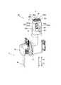
図1~図14を参照して、本実施形態による外科手術システム100の構成について説明する。外科手術システム100は、患者P側装置である医療用マニピュレータ1と、医療用マニピュレータ1を操作するための操作者側装置である遠隔操作装置2とを備えている。医療用マニピュレータ1は医療用台車3を備えており、移動可能に構成されている。遠隔操作装置2は、医療用マニピュレータ1から離間した位置に配置されており、医療用マニピュレータ1は、遠隔操作装置2により遠隔操作されるように構成されている。術者は、医療用マニピュレータ1に所望の動作を行わせるための指令を遠隔操作装置2に入力する。遠隔操作装置2は、入力された指令を医療用マニピュレータ1に送信する。医療用マニピュレータ1は、受信した指令に基づいて動作する。また、医療用マニピュレータ1は、滅菌された滅菌野である手術室内に配置されている。なお、外科手術システム100は、特許請求の範囲の「手術支援システム」の一例である。 The configuration of a
遠隔操作装置2は、たとえば、手術室の中または手術室の外に配置されている。遠隔操作装置2は、操作用マニピュレータアーム21と、操作ペダル22と、タッチパネル23と、モニタ24と、支持アーム25と、支持バー26とを含む。操作用マニピュレータアーム21は、術者が指令を入力するための操作用のハンドルを構成する。操作用マニピュレータアーム21は、医療器具4に対する操作量を受け付ける。モニタ24は、内視鏡により撮影された画像を表示するスコープ型表示装置である。支持アーム25は、モニタ24の高さを術者の顔の高さに合わせるようにモニタ24を支持する。タッチパネル23は、支持バー26に配置されている。医療用マニピュレータ1は、モニタ24近傍に設けられた図示しないセンサにより術者の頭部を検知することにより、遠隔操作装置2による操作が可能になる。術者は、モニタ24により患部を視認しながら、操作用マニピュレータアーム21および操作ペダル22を操作する。これにより、遠隔操作装置2に指令が入力される。遠隔操作装置2に入力された指令は、医療用マニピュレータ1に送信される。なお、操作用マニピュレータアーム21は、特許請求の範囲の「操作部」の一例である。 The
医療用台車3には、医療用マニピュレータ1の動作を制御する制御部31と、医療用マニピュレータ1の動作を制御するためのプログラムなどが記憶される記憶部32とが設けられている。そして、遠隔操作装置2に入力された指令に基づいて、医療用台車3の制御部31は、医療用マニピュレータ1の動作を制御する。 The
また、医療用台車3には、入力装置33が設けられている。入力装置33は、主に施術前に手術の準備を行うために、ポジショナ40、アームベース50、および、複数のアーム60の移動や姿勢の変更の操作を受け付けるように構成されている。 An
図1および図2に示す医療用マニピュレータ1は、手術室内に配置されている。医療用マニピュレータ1は、医療用台車3と、ポジショナ40と、アームベース50と、複数のアーム60とを備えている。アームベース50は、ポジショナ40の先端に取り付けられている。アームベース50は、比較的長い棒形状(長尺形状)を有する。また、複数のアーム60は、各々のアーム60の根元部が、アームベース50に取り付けられている。複数のアーム60は、折り畳まれた姿勢(収納姿勢)をとることが可能に構成されている。アームベース50と、複数のアーム60とは、図示しない滅菌ドレープにより覆われて使用される。 A
ポジショナ40は、たとえば、7軸多関節ロボットにより構成されている。また、ポジショナ40は、医療用台車3上に配置されている。ポジショナ40は、アームベース50を移動させる。具体的には、ポジショナ40は、アームベース50の位置を3次元に移動させるように構成されている。 The
また、ポジショナ40は、ベース部41と、ベース部41に連結された複数のリンク部42とを含む。複数のリンク部42同士は、関節部43により連結されている。 The
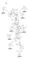
図1に示すように、複数のアーム60の各々の先端には、医療器具4が取り付けられている。医療器具4は、たとえば、取り換え可能なインストゥルメント、内視鏡6(図6参照)などを含む。 As shown in FIG. 1, the
図3に示すように、インストゥルメントには、アーム60のホルダ71に設けられたサーボモータM2によって駆動される被駆動ユニット4aが設けられている。また、インストゥルメントの先端には、エンドエフェクタとして鉗子4bが設けられている。なお、鉗子4bは、2つのエンドエフェクタ部材104aおよび104bを有している。 As shown in FIG. 3, the instrument is provided with a driven
また、図4に示すように、インストゥルメントは、エンドエフェクタ部材104aおよび104bの基端側を先端側でJ11軸周りに回転可能に支持する第1支持体4eと、第1支持体4eの基端側を先端側でJ10軸周りに回転可能に支持する第2支持体4fと、第2支持体4fの基端側に接続されるシャフト4cとを含む。被駆動ユニット4aと、シャフト4cと、第2支持体4fと、第1支持体4eと、鉗子4bとは、Z方向に沿って配置されている。J11軸は、シャフト4cが延びる方向(Z方向)に対して直交(z11方向、図12参照)する。また、J10軸は、シャフト4cが延びる方向においてJ11軸と離間しかつシャフト4cが延びる方向およびJ11軸に対して直交(z10方向、図12参照)する。 Also, as shown in FIG. 4, the instrument includes a
第1支持体4eには、J11軸の回転軸線R1周りに回転するように鉗子4bが取り付けられている。また、第2支持体4fは、第1支持体4eをJ10軸について回転可能に支持している。つまり、第2支持体4fにはJ10の回転軸線R2周りに回転するように第1支持体4eが取り付けられている。また、第1支持体4eの先端側(Z1方向側)の部分は、U字形状を有している。第1支持体4eのU字形状の先端側の部分の回転軸線R1方向における中央部にツールセンタポイント(TCP1、クレビス)が設定されている。 A
また、図6に示すように、内視鏡6のTCP2は、内視鏡6の先端に設定されている。 Further, as shown in FIG. 6 , the
次に、アーム60の構成について詳細に説明する。 Next, the configuration of
図3に示すように、アーム60は、アーム部61(ベース部62、リンク部63、関節部64)と、アーム部61の先端に設けられる並進移動機構部70とを含む。アーム60は、アーム60の根元側(アームベース50)に対して先端側を3次元に移動させるように構成されている。なお、複数のアーム60は、互いに同様の構成を有する。 As shown in FIG. 3 ,
並進移動機構部70は、アーム部61の先端側に設けられるとともに医療器具4が取り付けられている。また、並進移動機構部70は、医療器具4を患者Pに挿入する方向に並進移動させる。また、並進移動機構部70は、医療器具4をアーム部61に対して相対的に並進移動させるように構成されている。具体的には、並進移動機構部70には、医療器具4を保持するホルダ71が設けられている。ホルダ71には、サーボモータM2(図10参照)が収容されている。サーボモータM2は、医療器具4の被駆動ユニット4aに設けられた回転体を回転させるように構成されている。被駆動ユニット4aの回転体が回転されることにより、鉗子4bが動作される。 The translational
アーム部61は、7軸多関節ロボットアームから構成されている。また、アーム部61は、アーム部61をアームベース50に取り付けるためのベース部62と、ベース部62に連結された複数のリンク部63とを含む。複数のリンク部63同士は、関節部64により連結されている。 The
並進移動機構部70は、ホルダ71をZ方向に沿って並進移動させることにより、ホルダ71に取り付けられた医療器具4をZ方向(シャフト4cが延びる方向)に沿って並進移動させるように構成されている。具体的には、並進移動機構部70は、アーム部61の先端に接続される基端側リンク部72と、先端側リンク部73と、基端側リンク部72と先端側リンク部73との間に設けられる連結リンク部74とを含む。また、ホルダ71は、先端側リンク部73に設けられている。 The
そして、並進移動機構部70の連結リンク部74は、基端側リンク部72に対して、先端側リンク部73を、Z方向に沿って相対的に移動させる倍速機構として構成されている。また、基端側リンク部72に対して先端側リンク部73がZ方向に沿って相対的に移動されることにより、ホルダ71に設けられた医療器具4が、Z方向に沿って並進移動するように構成されている。また、アーム部61の先端は、基端側リンク部72を、Z方向に直交するX方向を軸として回動させるように基端側リンク部72に接続されている。 The connecting
また、図5に示すように、医療用マニピュレータ1は、アーム60に取り付けられ、アーム60を操作する操作部80を備えている。操作部80は、イネーブルスイッチ81と、ジョイスティック82とスイッチ部83とを含む。イネーブルスイッチ81は、ジョイスティック82およびスイッチ部83によるアーム60の移動を許可または不許可とする。また、イネーブルスイッチ81は、操作者(看護師、助手など)が操作部80を把持して押下されることによりアーム60による医療器具4の移動を許可する状態となる。 In addition, as shown in FIG. 5 , the
また、スイッチ部83は、医療器具4の長手方向に沿った医療器具4を患者Pに挿入する方向側に医療器具4を移動させるスイッチ部83aと、医療器具4を患者Pに挿入する方向と反対側に医療器具4を移動させるスイッチ部83bとを含む。スイッチ部83aとスイッチ部83bとは、共に、押しボタンスイッチから構成されている。 The
また、図5に示すように、操作部80は、アーム60に取り付けられた医療器具4の移動の支点(図9参照)となるピボット位置PPを教示するピボットボタン85を含む。ピボットボタン85は、操作部80の面80bに、イネーブルスイッチ81に隣り合うように設けられている。そして、内視鏡6(図6参照)またはピボット位置教示器具7(図7)の先端が、患者Pの体表面Sに挿入されたトロカールTの挿入位置に対応する位置まで移動された状態で、ピボットボタン85が押下されることによりピボット位置PPが教示され、記憶部32に記憶される。なお、ピボット位置PPの教示において、ピボット位置PPは、1つの点(座標)として設定され、ピボット位置PPの教示は、医療器具4の方向を設定するものではない。 Further, as shown in FIG. 5, the
また、図1に示すように、複数のアーム60のうちの一つのアーム60(たとえば、アーム60b)には内視鏡6が取り付けられ、残りのアーム60(たとえば、アーム60a、60cおよび60d)には、内視鏡6以外の医療器具4が取り付けられる。具体的には、手術において、4つのアーム60のうちの1つのアーム60に内視鏡6が取り付けられ、3つのアーム60に内視鏡6以外の医療器具4(鉗子4bなど)が取り付けられる。そして、内視鏡6が取り付けられているアーム60に対して、内視鏡6が取り付けられた状態でピボット位置PPが教示される。また、内視鏡6以外の医療器具4が取り付けられるアーム60に対して、ピボット位置教示器具7が取り付けられた状態でピボット位置PPが教示される。なお、内視鏡6は、互いに隣り合うように配置されている4つのアーム60のうちの、中央に配置される2つのアーム60(アーム60bおよび60c)のうちのいずれかに取り付けられる。すなわち、ピボット位置PPは、複数のアーム60毎に個別に設定される。Also, as shown in FIG. 1, the
また、図5に示すように、操作部80の面80bには、アーム60の位置を最適化するためのアジャストメントボタン86が設けられている。内視鏡6が取り付けられたアーム60に対するピボット位置PPの教示後、アジャストメントボタン86が押下さえることにより、他のアーム60(アームベース50)の位置が最適化される。 Further, as shown in FIG. 5, an
また、図5に示すように、操作部80は、アーム60に取り付けられた医療器具4を並進移動(図8参照)させるモードと、回転移動(図9参照)させるモードとを切り替えるモード切替ボタン84を含む。また、モード切替ボタン84の近傍には、モードインジケータ84aが設けられている。モードインジケータ84aは、切り替えられたモードを表示する。具体的には、モードインジケータ84aが点灯(回転移動モード)または消灯(並進移動モード)されることにより、現在のモード(並進移動モードまたは回転移動モード)が表示される。 Further, as shown in FIG. 5, the
また、モードインジケータ84aは、ピボット位置PPが教示されたことを表示するピボット位置インジケータを兼ねている。 The
図8に示すように、アーム60を並進移動させるモードでは、医療器具4の先端4dが、X-Y平面上において移動するように、アーム60が移動される。また、図9に示すように、アーム60を回転移動させるモードでは、ピボット位置PPが教示されていない時は、鉗子4bを中心に回転移動し、ピボット位置PPが教示されている時は、ピボット位置PPを支点として医療器具4が回転移動するように、アーム60が移動される。なお、医療器具4のシャフト4cがトロカールTに挿入された状態で、医療器具4が回転移動される。 As shown in FIG. 8, in the mode of translational movement of the
また、図10に示すように、アーム60には、アーム部61の複数の関節部64に対応するように、複数のサーボモータM1と、エンコーダE1と、減速機(図示せず)とが設けられている。エンコーダE1は、サーボモータM1の回転角を検出するように構成されている。減速機は、サーボモータM1の回転を減速させてトルクを増大させるように構成されている。 Further, as shown in FIG. 10, the
また、図10に示すように、並進移動機構部70には、医療器具4の被駆動ユニット4aに設けられた回転体を回転させるためのサーボモータM2と、医療器具4を並進移動させるためのサーボモータM3と、エンコーダE2およびエンコーダE3と、減速機(図示せず)とが設けられている。エンコーダE2およびエンコーダE3は、それぞれ、サーボモータM2およびサーボモータM3の回転角を検出するように構成されている。減速機は、サーボモータM2およびサーボモータM3の回転を減速させてトルクを増大させるように構成されている。 Further, as shown in FIG. 10, the translational
また、ポジショナ40には、ポジショナ40の複数の関節部43に対応するように、複数のサーボモータM4と、エンコーダE4と、減速機(図示せず)とが設けられている。エンコーダE4は、サーボモータM4の回転角を検出するように構成されている。減速機は、サーボモータM4の回転を減速させてトルクを増大させるように構成されている。 Further, the
また、医療用台車3には、医療用台車3の複数の前輪(図示せず)の各々を駆動するサーボモータM5と、エンコーダE5と、減速機(図示せず)とが設けられている。エンコーダE5は、サーボモータM5の回転角を検出するように構成されている。減速機は、サーボモータM5の回転を減速させてトルクを増大させるように構成されている。 The
医療用台車3の制御部31は、指令に基づいて複数のアーム60の移動を制御するアーム制御部31aと、指令に基づいてポジショナ40の移動および医療用台車3の前輪(図示せず)の駆動を制御するポジショナ制御部31bとを含む。アーム制御部31aには、アーム60を駆動するためのサーボモータM1を制御するためのサーボ制御部C1が電気的に接続されている。また、サーボ制御部C1には、サーボモータM1の回転角を検出するためのエンコーダE1が電気的に接続されている。 The
また、アーム制御部31aには、医療器具4を駆動するためのサーボモータM2を制御するためのサーボ制御部C2が電気的に接続されている。また、サーボ制御部C2には、サーボモータM2の回転角を検出するためのエンコーダE2が電気的に接続されている。また、アーム制御部31aには、並進移動機構部70を並進移動するためのサーボモータM3を制御するためのサーボ制御部C3が電気的に接続されている。また、サーボ制御部C3には、サーボモータM3の回転角を検出するためのエンコーダE3が電気的に接続されている。 A servo control unit C2 for controlling a servo motor M2 for driving the
そして、遠隔操作装置2に入力された動作指令が、アーム制御部31aに入力される。アーム制御部31aは、入力された動作指令と、エンコーダE1(E2、E3)により検出された回転角とに基づいて位置指令を生成するとともに、位置指令をサーボ制御部C1(C2、C2)に出力する。サーボ制御部C1(C2、C3)は、アーム制御部31aから入力された位置指令と、エンコーダE1(E2、E3)により検出された回転角とに基づいて、トルク指令を生成するとともに、トルク指令をサーボモータM1(M2、M3)に出力する。これにより、アーム60は、遠隔操作装置2に入力された動作指令に応じて移動する。 Then, the operation command input to the
また、アーム制御部31aは、操作部80のジョイスティック82からの入力信号に基づいてアーム60を操作する。具体的には、アーム制御部31aは、ジョイスティック82から入力された入力信号(動作指令)と、エンコーダE1により検出された回転角とに基づいて位置指令を生成するとともに、位置指令をサーボ制御部C1に出力する。サーボ制御部C1は、アーム制御部31aから入力された位置指令と、エンコーダE1により検出された回転角とに基づいて、トルク指令を生成するとともに、トルク指令をサーボモータM1に出力する。これにより、アーム60は、ジョイスティック82に入力された動作指令に応じて移動する。 The
アーム制御部31aは、操作部80のスイッチ部83からの入力信号に基づいてアーム60を操作するように構成されている。具体的には、アーム制御部31aは、スイッチ部83から入力された入力信号(動作指令)と、エンコーダE1またはE3により検出された回転角とに基づいて位置指令を生成するとともに、位置指令をサーボ制御部C1またはC3に出力する。サーボ制御部C1またはC3は、アーム制御部31aから入力された位置指令と、エンコーダE1またはE3により検出された回転角とに基づいて、トルク指令を生成するとともに、トルク指令をサーボモータM1またはM3に出力する。これにより、アーム60は、スイッチ部83に入力された動作指令に応じて移動する。
また、図10に示すように、ポジショナ制御部31bには、ポジショナ40を移動するサーボモータM4を制御するためのサーボ制御部C4が電気的に接続されている。また、サーボ制御部C4には、サーボモータM4の回転角を検出するためのエンコーダE4が電気的に接続されている。また、ポジショナ制御部31bには、医療用台車3の前輪(図示せず)を駆動するサーボモータM5を制御するためのサーボ制御部C5が電気的に接続されている。また、サーボ制御部C5には、サーボモータM5の回転角を検出するためのエンコーダE5が電気的に接続されている。 Further, as shown in FIG. 10, the
また、入力装置33からの動作指令が、ポジショナ制御部31bに入力される。ポジショナ制御部31bは、入力装置33から入力された動作指令と、エンコーダE4により検出された回転角とに基づいて位置指令を生成するとともに、位置指令をサーボ制御部C4に出力する。サーボ制御部C4は、ポジショナ制御部31bから入力された位置指令と、エンコーダE4により検出された回転角とに基づいて、トルク指令を生成するとともに、トルク指令をサーボモータM4に出力する。これにより、ポジショナ40は、入力装置33に入力された動作指令に応じて移動する。詳細な説明は省略するが、同様な手順により、ポジショナ制御部31bは、操作ハンドル34からの動作指令に応じて、医療用台車3を移動させる。 Further, an operation command from the
(アームの軸)
次に、図11を参照して、アーム60の軸について説明する。(Arm axis)
Next, referring to FIG. 11, the axis of
図11に示すように、アーム60は、回転軸としてのJ1~J7軸と、直動軸としてのJ8軸とを備えている。J1~J7軸は、アーム部61の関節部64の回転軸に対応する。また、J7軸は、並進移動機構部70(図3参照)の基端側リンク部72に対応する。J8軸は、並進移動機構部70の先端側リンク部73を基端側リンク部72に対してZ方向に沿って相対的に移動させる軸に対応する。すなわち、図10に示すサーボモータM1は、アーム60のJ1~J7軸に対応するように設けられている。また、サーボモータM3は、J8軸に対応するように設けられている。また、座標系1~座標系8は、各々、J1軸~J8軸の座標系を表す。 As shown in FIG. 11, the
(医療器具(鉗子)の軸)
次に、図12を参照して、医療器具4(鉗子4b)の軸について説明する。(Shaft of medical instrument (forceps))
Next, referring to FIG. 12, the axis of the medical instrument 4 (
図12に示すように、医療器具4(鉗子4b)は、シャフト4cの回転軸(シャフト4cが延びる方向に沿った軸)としてのJ9軸と、シャフト4cに接続される第2支持体4fの回転軸としてのJ10軸と、第1支持体4eに対して鉗子4bが回転する軸としてのJ11軸と、鉗子4bの開閉軸としてのJ12軸とを備えている。なお、アーム60のホルダ71に設けられたサーボモータM2は、複数(たとえば、4個)設けられており、複数のサーボモータM2によって、被駆動ユニット4aが駆動される。これにより、J9軸~J12軸周りに、医療器具4が駆動される。なお、J10軸およびJ11軸は、それぞれ、特許請求の範囲の「第2軸」および「第1軸」の一例である。また、座標系8~座標系11は、各々、J8軸~J11軸の座標系を表す。 As shown in FIG. 12, the medical instrument 4 (
制御部31は、遠隔操作装置2の操作用マニピュレータアーム21が受け付けた操作量に基づいて、アーム60と、アーム60に取り付けられた医療器具4(鉗子4b、内視鏡6)に対して、目標となる姿勢を作り出すための軸値(指令値)を算出する。具体的には、操作用マニピュレータアーム21からの操作に応じて、ピボット位置PPを中心として、アーム60および鉗子4b(または内視鏡6)が動作する。また、指令値を算出するために、アーム60の制御パラメータ、ピボット位置PP、医療器具4の制御パラメータが用いられる。また、アーム60の制御パラメータには、リンク長(各軸間の長さ)が含まれる。また、医療器具4の制御パラメータにも、リンク長(各軸間の長さ)が含まれる。 Based on the amount of operation received by the operating manipulator arm 21 of the
ここで、本実施形態では、図13に示すように、制御部31は、操作用マニピュレータアーム21が受け付けた医療器具4を回転させる動作を含む操作に応じた操作量に対するシャフト4cの回転速度ωに応じて、シャフト4cが延びる方向におけるJ10軸とJ11軸との間の長さL(図12参照)の制御パラメータを変化させて、医療器具4の動作を制御する。具体的には、制御部31は、シャフト4cの回転速度ω(J9軸の回転速度ω)が第1回転速度ω1以上である場合、J10軸とJ11軸との間の長さL(中間リンク長)の制御パラメータを小さくして、医療器具4の移動を制御する。シャフト4cの回転速度ωとは、ピボット位置PPを中心として、シャフト4cの回転軸であるJ9軸周りにシャフト4cが回転する際の回転速度ωを意味する。なお、第1回転速度ω1は、特許請求の範囲の「所定の回転速度」の一例である。 Here, in the present embodiment, as shown in FIG. 13, the
また、本実施形態では、制御部31は、回転速度ωが大きくなるにしたがってJ10軸とJ11軸との間の長さLの制御パラメータを徐々に小さくする。具体的には、制御部31は、回転速度ωが大きくなるにしたがってJ10軸とJ11軸との間の長さLの制御パラメータを線形的(直線的)に小さくする。 Further, in the present embodiment, the
詳細には、本実施形態では、制御部31は、回転速度ωが第1回転速度ω1以上かつ第1回転速度ω1よりも大きい第2回転速度ω2以下である場合、回転速度ωが大きくなるにしたがって制御パラメータを小さくする。また、制御部31は、回転速度ωが第2回転速度ω2を超える場合、制御パラメータを第2回転速度ω2に対応する一定の制御パラメータにする。たとえば、J10軸とJ11軸の実際の長さをLとした場合、第2回転速度ω2に対応する制御パラメータの大きさは、0.5Lである。 Specifically, in the present embodiment, when the rotation speed ω is equal to or greater than the first rotation speed ω1 and equal to or less than the second rotation speed ω2, which is greater than the first rotation speed ω1, the
すなわち、制御部31は、回転速度ωが第1回転速度ω1以上かつ第2回転速度ω2以下である場合、線形補完によって、回転速度ωに対応するJ10軸とJ11軸との間の長さLを算出する。また、制御部31は、J10軸とJ11軸との間の実際の長さLに対して、回転速度ωに対応する倍率(0.5以上1以下)を乗算することにより、回転速度ωに対応するJ10軸とJ11軸との間の長さLを算出する。That is, when the rotational speed ω is equal to or greater than the first rotational speed ω1 and equal to or less than the second rotational speed ω2, the
また、本実施形態では、制御部31は、回転速度ωが第1回転速度ω1未満である場合、J10軸とJ11軸との間の実際の長さLの制御パラメータを小さくせずに一定にする(つまり、倍率1.0を乗算する)。 Further, in the present embodiment, when the rotation speed ω is less than the first rotation speed ω1, the
たとえば、第1回転速度ω1は、シャフト4cの最大の回転速度ωの60%の値である。たとえば、第2回転速度ω2は、シャフト4cの最大の回転速度ωの90%の値である。 For example, the first rotation speed ω1 is 60% of the maximum rotation speed ω of the
また、本実施形態では、制御部31は、受け付けられた操作量に対する回転速度ωに応じた回転速度ωの指令値を生成する。そして、制御部31は、生成された指令値に対してローパスフィルタFを適用する。そして、制御部31は、ローパスフィルタFを適用した後のシャフト4cの回転速度ωの指令値が第1回転速度ω1以上である場合、J10軸とJ11軸との間の長さLの制御パラメータを小さくして、医療器具4の移動を制御する。 Further, in the present embodiment, the
また、制御部31は、医療用マニピュレータ1の動作中、常に、上記のシャフト4cの回転速度ωに基づく制御パラメータを変更する動作を行っている。つまり、制御部31は、は、第1支持体4eがJ10軸周りに回転してシャフト4cが延びる方向に対して交差するように医療器具4が屈曲していても(図14参照)、第1支持体4eがJ10軸周りに回転せずに医療器具4が屈曲していなくても(図4参照)、回転速度ωに基づく制御パラメータを変更する動作を行っている。ここで、医療器具4が屈曲した状態で、シャフト4cを比較的高速で回転させる場合にアーム60の振動が特に顕著に出現するので、医療器具4が屈曲した状態で、長さLの制御パラメータを小さくすることは、アーム60の振動を抑制する点において特に有効である。 In addition, the
(外科手術システムの制御方法)
次に、図15を参照して、外科手術システム100の制御方法について説明する。(Control method for surgical operation system)
Next, referring to FIG. 15, a method of controlling
まず、ステップS1において、制御部31は、医療器具4に対する操作であって、医療器具4を回転させる動作を含む操作を受け付ける。 First, in step S<b>1 , the
次に、ステップS2において、制御部31は、受け付けられた操作に応じたシャフト4cの回転速度ωに対して、ローパスフィルタFを適用する。 Next, in step S2, the
次に、ステップS3において、制御部31は、ローパスフィルタFが適用された後のシャフト4cの回転速度ωが、第1回転速度ω1未満であるか否かを判定する。ステップS3においてyesの場合、ステップS4において、制御部31は、J10軸とJ11軸との間の長さLの制御パラメータに積算する倍率を1.0に設定する。 Next, in step S3, the
そして、ステップS5において、設定された倍率に基づいて、アーム60を駆動する。 Then, in step S5, the
ステップS3においてnoの場合、ステップS6において、ローパスフィルタFが適用された後のシャフト4cの回転速度ωが、第2回転速度ω2以下であるか否かを判定する。ステップS6においてyesの場合、ステップS7において、制御部31は、線形補完により、シャフト4cの回転速度ωに対応する、実際の長さLに積算する倍率(0.5以上1.0以下)を算出するとともに、算出した倍率により長さLの制御パラメータを変更する。そして、ステップS5に進む。 If no in step S3, it is determined in step S6 whether or not the rotational speed ω of the
ステップS6においてnoの場合、ステップS8において、制御部31は、実際の長さLに積算する倍率を0.5とする。そして、ステップS5に進む。 In the case of no in step S6, the
上記のステップS1~S8の動作は、アーム60の動作中、常に行われるとともに、複数のアーム60毎に行なわれる。 The operations of steps S1 to S8 are always performed while the
[本実施形態の効果]
本実施形態では、以下のような効果を得ることができる。[Effect of this embodiment]
The following effects can be obtained in this embodiment.
(手術支援ロボット、医療用マニピュレータの効果)
本実施形態では、上記のように、制御部31は、受け付けられた操作量に対するシャフト4cの回転速度ωに応じて、シャフト4cが延びる方向におけるJ10軸とJ11軸との間の長さLの制御パラメータを変化させて、医療器具4の動作を制御する。これにより、シャフト4cの回転速度ωが大きくなった場合、J10軸とJ11軸との間の長さLの制御パラメータを小さくすることにより、制御の上では、シャフト4cの先端部(J11軸)と鉗子4b(J10軸)との間の距離が小さくなる。このため、シャフト4cを高速で回転させた場合に、鉗子4bの先端側の単位時間当たりの移動量が小さくなるので、アーム60の移動量の増加が抑制される。この結果、医療器具4のシャフト4cを高速で回転させた場合であっても、アーム60の振動を抑制できる。(Effects of surgical support robots and medical manipulators)
In the present embodiment, as described above, the
また、本実施形態では、上記のように、制御部31は、回転速度ωが大きくなるにしたがって制御パラメータを徐々に小さくする。ここで、制御パラメータが急激に変化する場合、制御点となるツールセンタポイントが急激に変化してしまい、アーム60の制御が複雑になる。そこで、上記のように制御パラメータを徐々に小さくすることにより、制御パラメータが変化した場合でも、アーム60の制御が複雑になるのを抑制することができる。また、制御点となるツールセンタポイントが急激に変化することに起因するアーム60の振動を抑制することができる。 Further, in the present embodiment, as described above, the
また、本実施形態では、上記のように、制御部31は、回転速度ωが大きくなるにしたがって制御パラメータを線形的に小さくする。これにより、制御パラメータが非線形に変化する場合と異なり、回転速度ωに対する制御パラメータを容易に算出することができる。 Further, in the present embodiment, as described above, the
また、本実施形態では、上記のように、制御部31は、回転速度ωが第1回転速度ω1以上かつ第1回転速度ω1よりも大きい第2回転速度ω2以下である場合、回転速度ωが大きくなるにしたがって制御パラメータを小さくし、回転速度ωが第2回転速度ω2を超える場合、制御パラメータを第2回転速度ω2に対応する一定の制御パラメータにする。これにより、回転速度ωが第2回転速度ω2を超えて大きくなる場合にも、制御パラメータが過度に小さくなることが抑制されるので、医療用マニピュレータ1を操作するユーザが、操作に対する違和感(ユーザが所望している鉗子4bの回転量と実際の回転量との差異)を感じるのを抑制することができる。 Further, in the present embodiment, as described above, when the rotation speed ω is equal to or greater than the first rotation speed ω1 and equal to or less than the second rotation speed ω2, which is greater than the first rotation speed ω1, the
また、本実施形態では、上記のように、制御部31は、回転速度ωが第1回転速度ω1未満である場合、制御パラメータを小さくせずに一定にする。ここで、シャフト4cの回転速度ωが第1回転速度ω1未満である場合では、回転速度ωが比較的小さいので、アーム60の振動が比較的小さい。そこで、上記のように回転速度ωが第1回転速度ω1未満である場合、制御パラメータを小さくせずに一定にすることによって、アーム60の振動を抑制しながら制御部31の制御負担を軽減することができる。 Further, in the present embodiment, as described above, when the rotation speed ω is less than the first rotation speed ω1, the
また、本実施形態では、上記のように、制御部31は、受け付けられた操作量に対する回転速度ωに応じた回転速度ωの指令値を生成し、生成された指令値に対してローパスフィルタFを適用し、ローパスフィルタFを適用した後の指令値が第1回転速度ω1以上である場合、制御パラメータを小さくして、医療器具4の動作を制御する。これにより、回転速度ωの指令値に含まれるノイズをローパスフィルタFによって除去することができる。 Further, in the present embodiment, as described above, the
また、本実施形態では、上記のように、制御部31は、第1支持体がJ10軸周りに回転してシャフト4cが延びる方向に対して交差するように医療器具4が屈曲した状態において、回転速度ωが第1回転速度ω1以上である場合、制御パラメータを小さくして、医療器具4の動作を制御する。ここで、医療器具4が屈曲した状態で、シャフト4cを比較的高速で回転させる場合にアーム60の振動が特に顕著に出現する。そこで、上記のように、シャフト4cが延びる方向に対して交差するように医療器具4が屈曲した状態において、回転速度ωが第1回転速度ω1以上である場合、制御パラメータを小さくすることは、アーム60の振動を抑制する点において特に有効である。 Further, in the present embodiment, as described above, the
(外科手術システムの制御方法の効果)
本実施形態では、上記のように、外科手術システム100の制御方法は、受け付けられた操作に応じた操作量に対するシャフト4cの回転速度ωに応じて、シャフト4cが延びる方向におけるJ10軸とJ11軸との間の長さLの制御パラメータを変化させて、医療器具4の動作を制御するステップを備える。これにより、医療器具4のシャフト4cを高速で回転させた場合であっても、アーム60の振動を抑制することができる。(Effect of Control Method of Surgical Operation System)
In the present embodiment, as described above, the control method of the
[変形例]
なお、今回開示された実施形態は、すべての点で例示であって制限的なものではないと考えられるべきである。本発明の範囲は、上記した実施形態の説明ではなく特許請求の範囲によって示され、さらに特許請求の範囲と均等の意味および範囲内でのすべての変更(変形例)が含まれる。[Modification]
It should be noted that the embodiments disclosed this time should be considered as examples and not restrictive in all respects. The scope of the present invention is indicated by the scope of the claims rather than the description of the above-described embodiments, and includes all modifications (modifications) within the meaning and scope equivalent to the scope of the claims.
たとえば、上記実施形態では、制御部31が医療用マニピュレータ1に設けられている例を示したが、本発明はこれに限られない。たとえば、制御部31が遠隔操作装置2に設けられていてもよい。また、たとえば、制御部31が医療用マニピュレータ1と遠隔操作装置2とは別に設けられていてもよい。 For example, in the above embodiment, an example in which the
また、上記実施形態では、制御部31は、シャフト4cの回転速度ωが大きくなるにしたがってJ10軸とJ11軸との間の長さLの制御パラメータを線形的に小さくする例を示したが、本発明はこれに限られない。たとえば、制御部31は、長さLの制御パラメータを指数関数的に小さくしてもよい。 In the above embodiment, the
また、上記実施形態では、制御部31は、シャフト4cの回転速度ωが第2回転速度ω2を超える場合、長さLの制御パラメータを一定にする例を示したが、本発明はこれに限られない。たとえば、制御部31は、シャフト4cの回転速度ωが第2回転速度ω2を超えても長さLの制御パラメータを徐々に小さくしてもよい。 In the above embodiment, the
また、上記実施形態では、制御部31は、シャフト4cの回転速度ωが第1回転速度ω1未満である場合、長さLの制御パラメータを小さくしない例を示したが、本発明はこれに限られない。たとえば、制御部31は、シャフト4cが回転すれば必ず、回転速度ωに応じで長さLの制御パラメータを小さくしてもよい。 In the above embodiment, the
また、上記実施形態では、回転速度ωの指令値に対してローパスフィルタFが適用される例を示したが、本発明はこれに限られない。たとえば、回転速度ωの指令値に含まれるノイズが小さい場合などでは、ローパスフィルタFを設けない構成も可能である。 Further, in the above-described embodiment, an example in which the low-pass filter F is applied to the command value of the rotation speed ω was shown, but the present invention is not limited to this. For example, when the noise included in the command value of the rotation speed ω is small, a configuration without the low-pass filter F is possible.
また、上記実施形態では、制御部31は、シャフト4cに対して、第1支持体4eが交差している(医療器具4が屈曲している)か否かにかかわず、長さLの制御パラメータを小さくする例を示したが、本発明はこれに限られない。たとえば、第1支持体4eがJ10軸周りに回転してシャフト4cが延びる方向に対して交差するように医療器具4が屈曲してした状態で(医療器具4が屈曲している場合のみにおいて)、シャフト4cの回転速度ωが第1回転速度ω1以上である場合、J10軸とJ11軸との間の長さLの制御パラメータを小さくして、医療器具4の移動を制御してもよい。これにより、医療器具4が屈曲していない状態では、長さLの制御パラメータを小さくする制御を行わないことによって、制御部31の制御負担を軽減することができる。 In the above embodiment, the
また、上記実施形態では、アーム60が4つ設けられている例を示したが、本発明はこれに限られない。本発明では、アーム60の数は、少なくとも1つ以上設けられていれば他の任意の数であってもよい。 Moreover, although the example in which the four
また、上記実施形態では、アーム部61およびポジショナ40が7軸多関節ロボットから構成されている例を示したが、本発明はこれに限られない。たとえば、アーム部61およびポジショナ40が7軸多関節ロボット以外の軸構成(例えば、6軸や8軸)の多関節ロボットなどから構成されていてもよい。 Further, in the above-described embodiment, an example in which the
また、上記実施形態では、医療用マニピュレータ1が、医療用台車3と、ポジショナ40と、アームベース50と、アーム60とを備えている例を示したが、本発明はこれに限らない。たとえば、医療用台車3と、ポジショナ40と、アームベース50は必ずしも必要なく、医療用マニピュレータ1がアーム60だけで構成されてもよい。 Moreover, although the
本明細書で開示する要素の機能は、開示された機能を実行するよう構成またはプログラムされた汎用プロセッサ、専用プロセッサ、集積回路、ASIC(Application Specific Integrated Circuits)、従来の回路、および/または、それらの組み合わせ、を含む回路または処理回路を使用して実行できる。プロセッサは、トランジスタやその他の回路を含むため、処理回路または回路と見なされる。本開示において、回路、ユニット、または手段は、列挙された機能を実行するハードウェアであるか、または、列挙された機能を実行するようにプログラムされたハードウェアである。ハードウェアは、本明細書に開示されているハードウェアであってもよいし、あるいは、列挙された機能を実行するようにプログラムまたは構成されているその他の既知のハードウェアであってもよい。ハードウェアが回路の一種と考えられるプロセッサである場合、回路、手段、またはユニットはハードウェアとソフトウェアの組み合わせであり、ソフトウェアはハードウェアおよび/またはプロセッサの構成に使用される。 The functionality of the elements disclosed herein may be accomplished using general purpose processors, special purpose processors, integrated circuits, Application Specific Integrated Circuits (ASICs), conventional circuits, and/or those configured or programmed to perform the disclosed functions. can be implemented using a circuit or processing circuit that includes a combination of A processor is considered a processing circuit or circuit because it includes transistors and other circuits. In this disclosure, a circuit, unit, or means is hardware that performs or is programmed to perform the recited functions. The hardware may be the hardware disclosed herein, or other known hardware programmed or configured to perform the recited functions. A circuit, means or unit is a combination of hardware and software where the hardware is a processor which is considered a type of circuit, the software being used to configure the hardware and/or the processor.
1 医療用マニピュレータ(患者側装置)
2 遠隔操作装置(操作者側装置)
4 医療器具
4b 鉗子(エンドエフェクタ)
4c シャフト
4e 第1支持体
4f 第2支持体
21 操作用マニピュレータアーム(操作部)
31 制御部
60 アーム
100 外科手術システム(手術支援システム)
F ローパスフィルタ
J10軸(第2軸)
J11軸(第1軸)
L (第1軸と第2軸との間の)長さ
ω 回転速度
ω1 第1回転速度
ω2 第2回転速度1 Medical manipulator (patient device)
2 Remote control device (operator side device)
4
31
F Low-pass filter J10 axis (2nd axis)
J11 axis (1st axis)
L length (between first and second axis) ω rotation speed ω1 first rotation speed ω2 second rotation speed
Claims (8)
Translated fromJapanese先端側に医療器具が取り付けられるアームを含む患者側装置と、
前記医療器具に対する操作を受け付ける操作部を含む操作者側装置と、
受け付けられた前記操作に応じた操作量に基づいて、前記医療器具の動作を制御する制御部と、
を備え、
前記医療器具は、
エンドエフェクタと、
第1支持体と、
第2支持体と、
前記第2支持体に接続されるシャフトと、
を含み、
前記第1支持体は、前記シャフトが延びる方向に対して直交する第1軸周りに、前記エンドエフェクタを回転可能に支持し、
前記第2支持体は、前記シャフトが延びる方向において前記第1軸と離間しかつ前記シャフトが延びる方向および前記第1軸に対して直交する第2軸周りに、前記第1支持体を回転可能に支持し、
前記制御部は、前記医療器具の前記シャフトを回転させる動作を含む前記操作に応じた前記操作量に基づいて、前記シャフトが延びる方向における前記第1軸と前記第2軸との間の長さの制御パラメータを用いて、前記アームおよび前記医療器具が目標となる姿勢を作り出すための指令値を算出するように構成されており、
前記制御部は、受け付けられた前記操作量に対する前記シャフトの回転速度が大きくなるにしたがって、制御の上で、前記制御パラメータを徐々に小さくして前記医療器具の動作を制御する、
手術支援システム。A surgery support system,
a patient side device including an arm to which a medical device is attached on the distal side;
an operator-side device including an operation unit that receives anoperation for the medical instrument;
a control unit that controls the operation of the medical device based on the operation amount corresponding to the accepted operation;
with
The medical device comprises:
an end effector;
a first support;
a second support;
a shaft connected to the second support;
including
the first support rotatably supports the end effector about a first axis perpendicular to the direction in which the shaft extends;
The second support is rotatable about a second axis that is separated from the first axis in the direction in which the shaft extends and that is perpendicular to the direction in which the shaft extends and the first axis. supported by
The control unit determines the length between the first axis and the second axis in the direction in which the shaft extends based on the operation amount corresponding to the operation including the operation of rotating the shaft of the medical device. is configured to calculate a command value for creating a target posture of the arm and the medical device using the control parameters of
The control unitcontrols the operation of the medical deviceby gradually decreasing thecontrol parameter as the rotation speedof the shaft increases with respect to the received operation amount.
Surgery support system.
前記回転速度が第1回転速度以上かつ前記第1回転速度よりも大きい第2回転速度以下である場合、前記回転速度が大きくなるにしたがって前記制御パラメータを小さくし、
前記回転速度が前記第2回転速度を超える場合、前記制御パラメータを前記第2回転速度に対応する一定の前記制御パラメータにする、請求項1または請求項2に記載の手術支援システム。The control unit
when the rotation speed is equal to or higher than a first rotation speed and equal to or lower than a second rotation speed, which is higher than the first rotation speed, the control parameter is decreased as the rotation speed increases;
The surgery assistance system according to claim1 or2 , wherein, when said rotational speed exceeds said second rotational speed, said control parameter is set to said constant control parameter corresponding to said second rotational speed.
受け付けられた前記操作量に対する前記回転速度に応じた前記回転速度の指令値を生成し、
生成された前記指令値に対してローパスフィルタを適用し、
前記ローパスフィルタが適用された前記指令値が前記第1回転速度以上である場合、前記制御パラメータを小さくして、前記医療器具の動作を制御する、請求項3から請求項5までのいずれか1項に記載の手術支援システム。The control unit
generating a command value of the rotation speed according to the rotation speed corresponding to the received operation amount;
Applying a low-pass filter to the generated command value,
Any one of claims3 to5 , wherein when the command value to which the low-pass filter is applied is equal to or higher than the first rotation speed, the control parameter is decreased to control the operation of the medical instrument. The surgery support system according to the item.
前記医療器具に対する操作を受け付ける操作部により受け付けられた前記操作に応じた操作量に基づいて、前記医療器具の動作を制御する制御部と、
を備え、
前記医療器具は、
エンドエフェクタと、
第1支持体と、
第2支持体と、
前記第2支持体に接続されるシャフトと、
を含み、
前記第1支持体は、前記シャフトが延びる方向に対して直交する第1軸周りに、前記エンドエフェクタを回転可能に支持し、
前記第2支持体は、前記シャフトが延びる方向において前記第1軸と離間しかつ前記シャフトが延びる方向および前記第1軸に対して直交する第2軸周りに、前記第1支持体を回転可能に支持し、
前記制御部は、前記医療器具を前記シャフト回りに回転させる動作を含む前記操作に応じた前記操作量に基づいて、前記シャフトが延びる方向における前記第1軸と前記第2軸との間の長さの制御パラメータを用いて、前記アームおよび前記医療器具が目標となる姿勢を作り出すための指令値を算出するように構成されており、
前記制御部は、受け付けられた前記操作量に対する前記シャフトの回転速度が大きくなるにしたがって、制御の上で、前記制御パラメータを徐々に小さくして前記医療器具の動作を制御する、
患者側装置。A patient-side device comprising an arm with a medical device attached to the distal end thereof,
a control unit that controls the operation of the medical device based on the amount of operation received by the operation unitthat receives the operation of the medical device;
with
The medical device comprises:
an end effector;
a first support;
a second support;
a shaft connected to the second support;
including
the first support rotatably supports the end effector about a first axis perpendicular to the direction in which the shaft extends;
The second support is rotatable about a second axis that is separated from the first axis in the direction in which the shaft extends and that is perpendicular to the direction in which the shaft extends and the first axis. supported by
The controller controls the length between the first axis and the second axis in the direction in which the shaft extends, based on the operation amount corresponding to the operation including the operation of rotating the medical device around the shaft. and calculating a command value for creating a target posture of the arm and the medical device using the control parameter of the height,
The control unitcontrols the operation of the medical instrumentby gradually decreasing thecontrol parameter as the rotation speedof the shaft increases with respect to the received operation amount.
Patient device.
前記操作部が、前記医療器具に対する前記操作であって、前記医療器具の前記シャフトを回転させる動作を含む操作を受け付けるステップと、
前記制御部が、受け付けられた前記操作に応じた前記操作量に対する前記シャフトの回転速度が大きくなるにしたがって、制御の上で、前記シャフトが延びる方向における前記第1軸と前記第2軸との間の長さの制御パラメータを徐々に小さくして、前記医療器具の動作を制御するステップとを備え、
前記制御部は、前記医療器具の前記シャフトを回転させる動作を含む前記操作に応じた前記操作量に基づいて、前記制御パラメータを用いて、前記アームおよび前記医療器具が目標となる姿勢を作り出すための指令値を算出するように構成されている、手術支援システムの制御方法。Based on a patient-side device including an arm to which a medical device is attached on the distal end side, an operator-side device including an operation unit that receives anoperation for the medical device, andan operation amount corresponding to the received operation, the medical treatment is performed.a controller for controlling operation of an instrument, the medical instrument comprising an end effector, a first support, a second support, and a shaft connected to the second support; A first support rotatably supports the end effector about a first axis orthogonal to the direction in which the shaft extends, and a second support supports the first axis in the direction in which the shaft extends. A control method for a surgical assistance system, wherein the first support body is rotatably supported around a second axis that is spaced apart and perpendicular to the direction in which the shaft extends and the first axis,
a step in which theoperation unit receives the operation on the medical instrument, the operation including an operation of rotatingthe shaft of the medical instrument;
As the rotation speedof the shaft increases with respect tothe operation amount corresponding tothe received operation, the control unit controls the rotation of the first axis and the second axis in the direction inwhich the shaft extends.gradually decreasing a control parameter of the length of time to control the operation of the medical device;
The control unit uses the control parameters to create a target posture of the arm and the medical device based on the operation amount corresponding to the operation including the operation of rotating the shaft of the medical device. A control method for a surgical assistance system configured to calculate a command value of .
Priority Applications (3)
| Application Number | Priority Date | Filing Date | Title |
|---|---|---|---|
| JP2020173392AJP7171669B2 (en) | 2020-10-14 | 2020-10-14 | Surgery support system, patient-side device, and control method for surgery support system |
| EP21202423.6AEP3984488A1 (en) | 2020-10-14 | 2021-10-13 | Robotic surgical system |
| US17/500,150US11890072B2 (en) | 2020-10-14 | 2021-10-13 | Robotic surgical system, patient-side apparatus, and control method of robotic surgical system |
Applications Claiming Priority (1)
| Application Number | Priority Date | Filing Date | Title |
|---|---|---|---|
| JP2020173392AJP7171669B2 (en) | 2020-10-14 | 2020-10-14 | Surgery support system, patient-side device, and control method for surgery support system |
Publications (2)
| Publication Number | Publication Date |
|---|---|
| JP2022064650A JP2022064650A (en) | 2022-04-26 |
| JP7171669B2true JP7171669B2 (en) | 2022-11-15 |
Family
ID=78179277
Family Applications (1)
| Application Number | Title | Priority Date | Filing Date |
|---|---|---|---|
| JP2020173392AActiveJP7171669B2 (en) | 2020-10-14 | 2020-10-14 | Surgery support system, patient-side device, and control method for surgery support system |
Country Status (3)
| Country | Link |
|---|---|
| US (1) | US11890072B2 (en) |
| EP (1) | EP3984488A1 (en) |
| JP (1) | JP7171669B2 (en) |
Citations (3)
| Publication number | Priority date | Publication date | Assignee | Title |
|---|---|---|---|---|
| JP2017538452A (en) | 2014-10-27 | 2017-12-28 | インテュイティブ サージカル オペレーションズ, インコーポレイテッド | System and method for alignment with an operating table |
| US20180049818A1 (en) | 2016-08-16 | 2018-02-22 | Ethicon Endo-Surgery, Llc | Control of the rate of actuation of tool mechanism based on inherent parameters |
| WO2018051665A1 (en) | 2016-09-13 | 2018-03-22 | ソニー株式会社 | Medical support arm device, medical system, and surgical microscope system |
Family Cites Families (19)
| Publication number | Priority date | Publication date | Assignee | Title |
|---|---|---|---|---|
| US6394998B1 (en) | 1999-01-22 | 2002-05-28 | Intuitive Surgical, Inc. | Surgical tools for use in minimally invasive telesurgical applications |
| US6793652B1 (en) | 1999-06-02 | 2004-09-21 | Power Medical Interventions, Inc. | Electro-mechanical surgical device |
| EP2000106B1 (en)* | 2001-02-08 | 2010-06-09 | Tyco Healthcare Group Lp | Ultrasonic surgical instrument |
| JP3952955B2 (en)* | 2003-01-17 | 2007-08-01 | トヨタ自動車株式会社 | Articulated robot |
| JP2005262340A (en)* | 2004-03-16 | 2005-09-29 | Fanuc Ltd | Industrial robot |
| US8644988B2 (en)* | 2010-05-14 | 2014-02-04 | Intuitive Surgical Operations, Inc. | Drive force control in medical instrument providing position measurements |
| JP5921943B2 (en) | 2012-04-12 | 2016-05-24 | カール シュトルツ ゲゼルシャフト ミット ベシュレンクテル ハフツング ウント コンパニー コマンディートゲゼルシャフト | Medical manipulator |
| JP6238628B2 (en)* | 2013-08-06 | 2017-11-29 | キヤノン株式会社 | Robot device, robot control method, robot control program, and part manufacturing method using robot device |
| JP6665095B2 (en)* | 2013-08-26 | 2020-03-13 | ブルックス オートメーション インコーポレイテッド | Substrate transfer device |
| JP6305076B2 (en)* | 2014-01-29 | 2018-04-04 | キヤノン株式会社 | Gear mechanism, transmission, and articulated robot arm |
| WO2016133633A1 (en) | 2015-02-19 | 2016-08-25 | Covidien Lp | Repositioning method of input device for robotic surgical system |
| GB201521804D0 (en)* | 2015-12-10 | 2016-01-27 | Cambridge Medical Robotics Ltd | Pulley arrangement for articulating a surgical instrument |
| US10350754B2 (en)* | 2016-09-27 | 2019-07-16 | Denso Wave Incorporated | Control device for robot |
| US11026758B2 (en)* | 2017-06-28 | 2021-06-08 | Auris Health, Inc. | Medical robotics systems implementing axis constraints during actuation of one or more motorized joints |
| BR112019013585A8 (en)* | 2017-06-29 | 2023-03-07 | Univ Texas | ENDOLUMINAL SURGICAL APPLIANCE, ENDOLUMINAL SURGERY METHOD AND SURGICAL INSTRUMENT |
| US11161243B2 (en)* | 2017-11-10 | 2021-11-02 | Intuitive Surgical Operations, Inc. | Systems and methods for controlling a robotic manipulator or associated tool |
| US11744604B2 (en)* | 2017-12-28 | 2023-09-05 | Cilag Gmbh International | Surgical instrument with a hardware-only control circuit |
| JP7404627B2 (en)* | 2019-03-13 | 2023-12-26 | セイコーエプソン株式会社 | Robot system, control device, and control method |
| JP7009428B2 (en)* | 2019-09-26 | 2022-01-25 | 株式会社メディカロイド | Surgical instruments |
- 2020
- 2020-10-14JPJP2020173392Apatent/JP7171669B2/enactiveActive
- 2021
- 2021-10-13EPEP21202423.6Apatent/EP3984488A1/enactivePending
- 2021-10-13USUS17/500,150patent/US11890072B2/enactiveActive
Patent Citations (3)
| Publication number | Priority date | Publication date | Assignee | Title |
|---|---|---|---|---|
| JP2017538452A (en) | 2014-10-27 | 2017-12-28 | インテュイティブ サージカル オペレーションズ, インコーポレイテッド | System and method for alignment with an operating table |
| US20180049818A1 (en) | 2016-08-16 | 2018-02-22 | Ethicon Endo-Surgery, Llc | Control of the rate of actuation of tool mechanism based on inherent parameters |
| WO2018051665A1 (en) | 2016-09-13 | 2018-03-22 | ソニー株式会社 | Medical support arm device, medical system, and surgical microscope system |
Also Published As
| Publication number | Publication date |
|---|---|
| US20220110702A1 (en) | 2022-04-14 |
| US11890072B2 (en) | 2024-02-06 |
| JP2022064650A (en) | 2022-04-26 |
| EP3984488A1 (en) | 2022-04-20 |
Similar Documents
| Publication | Publication Date | Title |
|---|---|---|
| JP7518885B2 (en) | Surgical system and operating device | |
| JP7746073B2 (en) | Surgery support system and method for controlling the surgery support system | |
| JP7196226B2 (en) | Surgery support robot | |
| US20230068780A1 (en) | Robotic surgical system and control method of robotic surgical system | |
| EP4101414A1 (en) | Robotic surgical system | |
| CN114469346B (en) | Surgical assistance system, control device and control method for surgical assistance system | |
| JP2025137777A (en) | Surgery support system, control device for surgery support system, and control method for surgery support system | |
| JP2023018313A (en) | Surgery support system and pivot position setting method | |
| JP7171669B2 (en) | Surgery support system, patient-side device, and control method for surgery support system | |
| JP7295831B2 (en) | Surgery support system, patient-side device and calculation method | |
| JP2021175501A (en) | Surgery support robot | |
| JP7068379B2 (en) | Surgery support robot | |
| JP7748263B2 (en) | Surgery Support System | |
| JP2024017839A (en) | Surgical instruments and surgical support robots | |
| JP2023020582A (en) | Surgery support system, operator-side device, and control method for surgery support system | |
| JP2022123258A (en) | Surgery support system, patient-side device, and control method for surgery support system | |
| WO2022168510A1 (en) | Surgery assistance robot, surgery assistance system, and method for controlling surgery assistance robot |
Legal Events
| Date | Code | Title | Description |
|---|---|---|---|
| RD01 | Notification of change of attorney | Free format text:JAPANESE INTERMEDIATE CODE: A7426 Effective date:20201022 | |
| A521 | Request for written amendment filed | Free format text:JAPANESE INTERMEDIATE CODE: A821 Effective date:20201026 | |
| A621 | Written request for application examination | Free format text:JAPANESE INTERMEDIATE CODE: A621 Effective date:20210614 | |
| A131 | Notification of reasons for refusal | Free format text:JAPANESE INTERMEDIATE CODE: A131 Effective date:20220726 | |
| A521 | Request for written amendment filed | Free format text:JAPANESE INTERMEDIATE CODE: A523 Effective date:20220915 | |
| TRDD | Decision of grant or rejection written | ||
| A01 | Written decision to grant a patent or to grant a registration (utility model) | Free format text:JAPANESE INTERMEDIATE CODE: A01 Effective date:20221025 | |
| A61 | First payment of annual fees (during grant procedure) | Free format text:JAPANESE INTERMEDIATE CODE: A61 Effective date:20221102 | |
| R150 | Certificate of patent or registration of utility model | Ref document number:7171669 Country of ref document:JP Free format text:JAPANESE INTERMEDIATE CODE: R150 | |
| S111 | Request for change of ownership or part of ownership | Free format text:JAPANESE INTERMEDIATE CODE: R313117 | |
| R350 | Written notification of registration of transfer | Free format text:JAPANESE INTERMEDIATE CODE: R350 |