JP7170317B2 - Tabletop and detachable operating table - Google Patents
Tabletop and detachable operating tableDownload PDFInfo
- Publication number
- JP7170317B2 JP7170317B2JP2019005815AJP2019005815AJP7170317B2JP 7170317 B2JP7170317 B2JP 7170317B2JP 2019005815 AJP2019005815 AJP 2019005815AJP 2019005815 AJP2019005815 AJP 2019005815AJP 7170317 B2JP7170317 B2JP 7170317B2
- Authority
- JP
- Japan
- Prior art keywords
- table top
- patient
- area
- column
- region
- Prior art date
- Legal status (The legal status is an assumption and is not a legal conclusion. Google has not performed a legal analysis and makes no representation as to the accuracy of the status listed.)
- Active
Links
Images


Landscapes
- Accommodation For Nursing Or Treatment Tables (AREA)
Description
Translated fromJapanese特許法第30条第2項適用 (1)平成30年5月17日~平成30年5月18日 第35回 日本呼吸器外科学会総会・学術集会にて公開 (2)平成30年5月17日~平成30年5月18日 第35回 日本呼吸器外科学会総会・学術集会にてちらしの配布Application of
本発明は、手術を受ける患者を載置するためのテーブルトップ、及びコラムから前記テーブルトップを分離させることが可能な分離式手術台に関する。 The present invention relates to a table top for placing a patient undergoing surgery, and to a detachable operating table that allows the table top to be detached from the column.
外科手術を受ける患者の体位は、その術式に応じて異なる。外科手術の最中、患者は、その術式が行いやすい所定の体位に固定される。例えば、外科手術で最も一般的な体位は、仰臥位である。脊椎外科手術は、患者を腹臥位に固定して行われる。胸部外科手術は、患者を仰臥位、側臥位又は半側臥位に固定して行われる。膀胱、前立腺、尿道、膣、子宮、肛門、直腸などの外科手術は、患者を砕石位に固定して行われる。 The position of a patient undergoing surgery varies depending on the surgical procedure. During surgery, the patient is fixed in a predetermined position that facilitates the surgical procedure. For example, the most common body position in surgery is the supine position. Spinal surgery is performed with the patient immobilized in a prone position. Thoracic surgery is performed with the patient immobilized in a supine, lateral or semi-lateral position. Bladder, prostate, urethral, vaginal, uterine, anal, and rectal surgeries are performed with the patient fixed in a lithotripsy position.
そこで、外科手術には、患者を様々な体位に固定することが可能な多目的手術台が用いられる。例えば、非特許文献1に開示された多目的手術台は、主として、テーブルトップとコラムとで構成される。テーブルトップは、第1~第4領域で構成され、各領域を分離することが可能となっている。第1領域には、患者の頭部が載置される。第2領域には、患者の胸部及び腹部が載置される。第4領域には、患者の脚部が載置される。第4領域は、左右に2分割されており、左側部分には患者の左脚が載置され、右側部分には患者の右脚が載置される。患者を開脚させるために、第4領域の左側部分と右側部分とは、互いに離反する方向に回動することが可能である。このようなテーブルトップの姿勢は、コラムによって上下方向、前後方向及び左右方向に変化される。 Therefore, a multi-purpose operating table is used for surgical operations, on which a patient can be fixed in various positions. For example, the multi-purpose operating table disclosed in Non-Patent
さらに、術式に応じて患者の体位を固定する場合には、非特許文献2に開示されたアクセサリーを用いる。上述したテーブルトップの両側には、金属製のレールが設けられている。これらのレールに様々なアクセサリーを固定することが可能である。これらのアクセサリーは、いずれも患者の身体の所定部位を固定するか、又は支持する。 Furthermore, the accessory disclosed in Non-Patent
<胸部外科手術に関する問題1>
胸部外科手術、例えば、肺切除術は、患者を側臥位に固定して行われる。側臥位とは、患者を約90°の横向きに寝かせることをいう。患者を側臥位に固定する場合には、非特許文献2に開示された側部支持器が用いられる。しかし、側部支持器によって、患者を無理のない体位に固定することは困難であった。<
Thoracic surgery, such as pneumonectomy, is performed with the patient fixed in a lateral decubitus position. Lateral position refers to laying the patient on their side at approximately 90°. When fixing the patient in the lateral recumbent position, the side support device disclosed in Non-Patent
すなわち、側部支持器の面積は小さい。患者を側臥位に固定する場合は、患者の身体を正面側及び背面側から押えるための、少なくとも2つの側部支持器が用いられる。しかし、面積の小さい側部支持器を患者の身体に直接当てると、患者の身体が局所的に圧迫されてしまう。このため、側部支持器と患者の身体との間に、圧力を分散させるための柔軟なパッドを介在させる必要があった。 That is, the area of the side supports is small. When fixing the patient in the lateral recumbent position, at least two side supports are used to support the patient's body from the front and back sides. However, if the side support having a small area is applied directly to the patient's body, the patient's body will be locally compressed. This has necessitated the interposition of flexible pads between the side supports and the patient's body to distribute the pressure.
患者を無理のない体位に固定するためには、2つの側部支持器の取付位置、高さ、患者の身体までの距離を調整した後、側部支持器と患者の身体との間にパッドを介在させ、局所的な圧迫がないことを確認しなければならない。局所的な圧迫がある場合は、側部支持器やパッドの状態を再調整しなければならない。このように、側部支持器とパッドとの組み合わせでは、患者を無理のない体位に固定することが難しく、調整に手間が掛かる。 To fix the patient in a comfortable position, after adjusting the mounting position, height, and distance to the patient's body of the two side supports, a pad is placed between the side supports and the patient's body. should be interposed and ensured that there is no local compression. If there is localized pressure, the side support or padding should be readjusted. In this way, it is difficult to fix the patient in a comfortable position with the combination of the side support and the pad, and adjustment is troublesome.
<胸部外科手術に関する問題2>
側部支持器及びパッドは、患者の身体を正面側及び背面側から押えて、テーブルトップの中央に固定する。このため、胸部外科手術を行う医者と患者との間には、側部支持器及びパッドに相当する距離が生じる。この結果、医者は、開胸部に接近して手術を行うことができなくなる。また、側部支持器及びパッドは、開胸部付近のスペースを物理的に占有し、医者や手術スタッフが作業をするためのスペースを減少させる。<
Side supports and pads hold the patient's body from the front and back and secure it to the center of the tabletop. This creates a distance equivalent to the side supports and pads between the doctor performing the thoracic surgery and the patient. As a result, physicians cannot access the thoracotomy to perform surgery. Also, the side supports and pads physically occupy space near the thoracotomy, reducing the space in which the doctor and surgical staff work.
<胸部外科手術に関する問題3>
心臓は、胸骨、肋骨、鎖骨、椎体で囲まれる「胸郭」というスペース内の前方に位置している。心臓は、胸郭の中で胸骨の真下に位置する。このため、心臓の外科手術は、一般に「胸骨正中切開術」という術式で行われる。胸骨正中切開術は、患者の胸の中央を縦方向に正中切開する。患者の皮膚及び胸骨を2分割し、開胸器によって胸骨を左右に広げて術野を確保する。胸骨の下の心膜を切開すると、心臓に到達する。このような胸骨正中切開術は、患者の胸を反らせた仰臥位で行われる。患者の胸を反らせた状態にするために、従来は、患者の背面とテーブルトップとの間にパッドや枕を敷いて、患者の胸を反らせた状態にしていた。しかし、パッドや枕では、最適な高さに調整することが難しく、一定の高さを長時間にわたって維持できない問題がある。<
The heart is located forward in a space called the “thorax,” bounded by the sternum, ribs, clavicle, and vertebral bodies. The heart is located in the rib cage just below the sternum. For this reason, heart surgery is generally performed in a surgical procedure called "median sternotomy". A median sternotomy is a longitudinal midline incision in the center of the patient's chest. The patient's skin and sternum are divided into two parts, and the sternum is spread left and right using a thoracotomy to secure the surgical field. An incision is made in the pericardium below the sternum to access the heart. Such a median sternotomy is performed with the patient in the supine position with the chest arched. Conventionally, a pad or pillow is placed between the patient's back and the table top to hold the patient's chest in an arched position. However, with pads and pillows, it is difficult to adjust the height to an optimum level, and there is a problem that a constant height cannot be maintained for a long period of time.
一方、特開2002-126017号公報(特許文献1)には、患者の身体のうち、膵臓に対応する部分を挙上させて、患者の胸を反らせた状態にする腹部外科手術用の手術台が開示されている。しかし、心臓外科の胸骨正中切開術では、膵臓に対応する部分を挙上させても、開胸部において良好な術野を得ることはできない。 On the other hand, Japanese Unexamined Patent Application Publication No. 2002-126017 (Patent Document 1) discloses an operating table for abdominal surgery in which a portion of the patient's body corresponding to the pancreas is elevated so that the patient's chest is arched. is disclosed. However, in median sternotomy in cardiac surgery, even if the part corresponding to the pancreas is elevated, a good surgical field cannot be obtained in the thoracotomy.
<発明の目的>
本発明は、上記の問題点に鑑みてなされたものであり、胸部外科手術に好適な下記の技術的効果を奏するテーブルトップ及び分離式手術台を提供することを目的とする。
-アクセサリーを用いずに、胸部外科手術に好適な体位を容易に実現できる。
-開胸部付近の作業スペースを拡張でき、医者が開胸部により接近して手術できる。<Purpose of Invention>
SUMMARY OF THE INVENTION It is an object of the present invention to provide a table top and a separate operating table that are suitable for thoracic surgery and have the following technical effects.
- Allows easy realization of the preferred body position for thoracic surgery without the use of accessories.
- The working space near the thoracotomy can be expanded, allowing the doctor to operate closer to the thoracotomy.
(1)上記目的を達成するために、本発明のテーブルトップは、手術を受ける患者を載置するためのテーブルトップであって、前記患者の頭部が載置される第1領域と、前記患者の胸部及び腹部が載置される第2領域と、前記患者の腰部が載置される第3領域と、前記患者の脚部が載置される第4領域と、を含み、前記第1領域は、中央と左右とに3分割され、前記第1領域の左右部分は、いずれも前記テーブルトップの長手方向に摺動可能に構成され、前記第2領域は、中央と左右とに3分割され、前記第2領域の左右部分は、いずれも前記テーブルトップの短手方向に摺動可能、且つ前記テーブルトップの長手方向の軸を中心にして上下方向に回動することが可能に構成され、前記第2領域の中央部分は、前記胸部側と前記腹部側とに2分割され、前記胸部側の部分が昇降可能に構成される。(1) In order to achieve the above object, the table top of the present invention is a table top for placing a patient undergoing surgery, comprising: a first region on which the patient's head is placed; a second region on which the patient's chest and abdomen are placed; a third region on which the patient's waist is placed; and a fourth region on which the patient's legs are placed; The area is divided into three parts, the center and the left and right parts. Both the left and right parts of the first area are configured to be slidable in the longitudinal direction of the table top, and the second area is divided into three parts, the center and the left and right parts. Both the left and right portions of the second region are configured to be slidable in the lateral direction of the table top and to be vertically rotatable about the longitudinal axis of the table top. , the central portion of the second region is divided into the chest side and the abdomen side, and the chest side portion is configured to be movable up and down.
(2)好ましくは、上記(1)のテーブルトップにおいて、前記第2領域の中央部分のうちの前記胸部側の部分の面積が、前記腹部側の部分の面積よりも大きい。(2) Preferably, in the table top of (1) above, the area of the chest side portion of the central portion of the second region is larger than the area of the abdomen side portion.
(3)好ましくは、上記(1)又は(2)のテーブルトップにおいて、前記第4領域が、前記第3領域から着脱自在に構成される。(3) Preferably, in the table top of (1) or (2) above, the fourth area is detachably attached to the third area.
(4)好ましくは、上記(3)のテーブルトップにおいて、前記第4領域が、前後方向に2分割され、分割された部分どうしが、互いに着脱自在に構成される。(4) Preferably, in the table top of (3) above, the fourth region is divided into two in the front-rear direction, and the divided portions are detachable from each other.
(5)好ましくは、上記(1)~(4)のいずれかのテーブルトップにおいて、前記第2領域の左部分を上下方向に回動させるための第1電気モータと、前記第2領域の右部分を上下方向に回動させるための第2電気モータと、前記第2領域の中央部分のうちの前記胸部側の部分を昇降させるための第3電気モータと、を備える。(5) Preferably, in the table top according to any one of (1) to (4) above, a first electric motor for vertically rotating the left part of the second area and a right part of the second area a second electric motor for vertically rotating the portion; and a third electric motor for vertically moving the chest-side portion of the central portion of the second region.
(6)上記目的を達成するために、本発明の分離式手術台は、上記(5)に記載のテーブルトップと、前記テーブルトップの姿勢を変化させることが可能なコラムとを備え、前記コラムから前記テーブルトップを分離させることが可能な分離式手術台であって、前記テーブルトップ及び前記コラムのそれぞれは、互いに着脱自在な結合部を備え、前記結合部を介して、前記コラムから前記テーブルトップに電源が供給されるように構成され、前記コラムは、操作部と、制御部と、駆動機構とをさらに備え、前記操作部は、ユーザーによるコマンドの入力が可能となるように構成され、前記制御部は、前記コマンドに基づいて、前記第1~第3電気モータ及び前記駆動機構の動作を制御し、前記駆動機構は、前記結合部によって結合された前記テーブルトップの姿勢を上下方向、前後方向及び左右方向に変化させる。(6) In order to achieve the above object, a separable operating table of the present invention comprises the table top according to the above (5) and a column capable of changing the posture of the table top, wherein the column wherein the table top and the column each comprise a joint detachable from each other, the column being separated from the table via the joint; The top is configured to be powered, the column further includes an operation unit, a control unit, and a drive mechanism, the operation unit is configured to allow a user to input commands, The control unit controls the operations of the first to third electric motors and the drive mechanism based on the command, and the drive mechanism vertically changes the posture of the table top coupled by the coupling unit. It is changed in the front-rear direction and the left-right direction.
本発明のテーブルトップ及び分離式手術台によれば、アクセサリーを用いずに、胸部外科手術に好適な体位を容易に実現できる。また、開胸部付近の作業スペースを拡張でき、医者が開胸部により接近して手術できる。 With the table top and detachable operating table of the present invention, a suitable body position for thoracic surgery can be easily realized without accessories. In addition, the working space around the thoracotomy can be expanded, and the doctor can operate closer to the thoracotomy.
以下、本発明の実施形態に係るテーブルトップ、コラム及び分離式手術台について、図面を参照しつつ説明する。 BEST MODE FOR CARRYING OUT THE INVENTION A table top, a column, and a separate operating table according to embodiments of the present invention will be described below with reference to the drawings.
なお、以下の説明における前後、左右、上下の方向は、図1(a)及び図7中の矢印によって示される。図10(a)に示すように、本実施形態のテーブルトップ1に仰臥位(仰向け)で載置された患者を基準にして、頭部の方向を「前」、脚部の方向を「後」、右手の方向を「右」、左手の方向を「左」、腹部の向く方向を「上」、背部の向く方向を「下」と定義する。また、「長手方向」は、テーブルトップ1の前後方向と同じであり、「短手方向」は、テーブルトップ1の左右方向と同じである。 In addition, the directions of front and back, left and right, and up and down in the following description are indicated by arrows in FIGS. As shown in FIG. 10(a), with the patient placed on the
<テーブルトップ全体の構成>
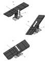
まず、本実施形態のテーブルトップ1について、図1~図5を参照して説明する。図1(a)~(c)は、本実施形態のテーブルトップ1全体の構成を示す。テーブルトップ1全体の外観は、主として、金属製のフレーム51と、柔軟なマットレス52とで構成されており、長手方向に4つの領域1A~1Dに区別される。第1領域1Aには、患者の頭部及び肩部が載置される。第2の領域1Bには、患者の胸部、腹部及び両腕が載置される。第3の領域1Cには、患者の腰部が載置される。第4の領域1Dには、患者の脚部が載置される。<Composition of the entire table top>
First, the
図1(a)に示すように、第1領域1Aは、中央と左右とに3分割される。中央の頭板10Aには、患者の頭部が載置される。左右の肩板10B、10Cには、患者の両肩が載置される。図1(c)に示すように、肩板10B、10Cは、いずれもテーブルトップ1の長手方向に手動で摺動可能となるように構成される。肩板10B、10Cの構成及び動作については、後に詳しく説明する。 As shown in FIG. 1(a), the
図1(a)に示すように、第2領域1Bは、中央と左右とに3分割され、このうち左右部分は、電動ウイング20A、20Bで構成される。図1(c)に示すように、電動ウイング20A、20Bは、いずれもテーブルトップ1の短手方向に手動で摺動可能であり、且つテーブルトップ1の長手方向に延びる回転軸23、23を中心にして上下方向に回動することが可能である。電動ウイング20A、20Bの構成及び動作については、後に詳しく説明する。 As shown in FIG. 1(a), the
図1(a)に示すように、第2領域1Bの中央部分は、さらに胸部側と腹部側とに2分割される。このうち胸部側の部分は、昇降可能な電動挙上器20Cで構成される。電動挙上器20Cの構成及び動作については、後に詳しく説明する。腹部側の部分は、患者の背部が載置される背板20Dで構成される。図1(c)に示すように、背板20Dは、第1領域1Aの頭板10Aを支持する2つのフレーム51に支持される。背板20Dの下側には、電動挙上器20Cを動作させるための第3電気モータ26が収納される。第3電気モータ26として、例えば、入力される駆動パルスの数に比例して動作するステッピングモータを用いる。 As shown in FIG. 1(a), the central portion of the
図1(a)に示すように、第3領域1Cは、患者の腰部が載置される腰板30で構成される。図1(c)に示すように、腰板30を支持するフレーム51は、上述した頭板10A及び背板20Dを支持するフレーム51と連結される。腰板30の下側には、上述した電動ウイング20A、20Bを個別に動作させるための第1及び第2電気モータ24、25が収納される。第1及び第2電気モータ24、25として、例えば、入力される駆動パルスの数に比例して動作するステッピングモータを用いる。 As shown in FIG. 1(a), the
さらに、腰板30の下側には、第1~第3電気モータ24~26に駆動パルスを供給するための図示しない配線が収納される。これらの配線は、一対の結合部31、31を介して、図6に示すコラム2と電気的に接続される。一対の結合部31、31は、腰板30の下側の左右に設けられており、コラム2と機械的及び電気的に結合することが可能となっている。コラム2の構成及び動作については、後に詳しく説明する。 Further, wiring (not shown) for supplying driving pulses to the first to third
図1(a)に示すように、第4領域1Dは、患者の脚部が載置される2つの脚板40A、40Bで構成される。脚板40A、40Bは、テーブルトップ1から個別に取り外すことが可能である。図1(c)に示すように、前側の脚板40Aを支持するフレーム51は、腰板30を支持するフレーム51に対して着脱自在となっている。一方、後側の脚板40Bを支持するフレーム51は、前側の脚板40Aを支持するフレーム51に対して着脱自在となっている。 As shown in FIG. 1(a), the
肩板10B、10C、腰板30、脚板40A、40Bを支えるそれぞれのフレーム51の側面には、金属製のレール53が取り付けられる。各レール53には、テーブルトップ1に寝かされた患者を支援するための様々なアクセサリーを固定することが可能である。 A
<電動ウイング>
次に、上述した電動ウイング20A、20Bの構成及び動作について、図1(c)及び図2(a)~(d)を参照しつつ説明する。<Electric wing>
Next, the configuration and operation of the
図1(c)に示すように、左右の電動ウイング20A、20Bは、それぞれ2つのスライダ21、21に固定される。2つのスライダ21、21は、テーブルトップ1の短手方向に延びる2つの平行なスライドレール22、22(図2を参照)に摺動可能に取り付けられる。各スライドレール22は、テーブルトップ1の長手方向に延びる回転軸23に固定される。左の電動ウイング20Aを回動させるための回転軸23は、第1電気モータ24に結合される。右の電動ウイング20Bを回動させるための回転軸23は、第2電気モータ25に結合される。 As shown in FIG. 1(c), the left and right
図2(a)、(b)に示すように、電動ウイング20A、20Bは、各スライドレール22に沿って手動で個別に摺動させることが可能である。水平状態の電動ウイング20A、20Bを摺動させることにより、テーブルトップ1の第2領域1Bの幅を拡張することができる。また、図2(c)に示すように、上方向に回動させた電動ウイング20A、20Bを摺動させることにより、電動ウイング20A、20Bの高さを調整することができる。医者又は手術スタッフは、患者の体型及び所望する体位に応じて、電動ウイング20A、20Bのそれぞれの位置を最適に調整することができる。 As shown in FIGS. 2(a) and 2(b), the
図2(c)、(d)に示すように、本実施形態の電動ウイング20A、20Bは、回転軸23、23を中心にして、上下方向に±90°の範囲内で回動することが可能である。電動ウイング20A、20Bの回動は、図6に示すコラム2によって制御される。コラム2は、医者又は手術スタッフによって入力されたコマンドに基づき、第1及び/又は第2電気モータ24、25を正方向又は逆方向に所定量だけ回転させるための駆動パルスを出力する。この駆動パルスは、図1(c)に示す一対の結合部31、31を介して、第1及び/又は第2電気モータ24、25に入力される。第1及び/又は第2電気モータ24、25の回転運動を受けて、電動ウイング20A、20Bが、上下方向に±90°の範囲内で回動する。医者又は手術スタッフは、コラム2の後述する操作部62を操作するか、又は図示しないリモートコントローラーを操作して、電動ウイング20A、20Bの角度を最適に調整することできる。 As shown in FIGS. 2(c) and 2(d), the
<電動挙上器>
次に、上述した電動挙上器20Cの構成及び動作について、図3(a)~(c)及び図4(a)~(c)を参照しつつ説明する。<Electric Lifter>
Next, the configuration and operation of the
図3(a)~(c)に示すように、電動挙上器20Cは、テーブルトップ1の第2領域1Bの中央、且つ胸部側に位置する。本実施形態の電動挙上器20Cは、上下方向に0mm~60mmの範囲内で昇降することが可能である。また、図1(a)に示すように、電動挙上器20Cによって昇降されるマットレス52の面積は、背板20Dのマットレス52の面積よりも大きい。電動挙上器20Cによって昇降されるマットレス52の面積が大きいほど、患者の身体への圧迫が軽減される。 As shown in FIGS. 3(a) to 3(c), the
図4(a)~(c)に示すように、電動挙上器20Cは、第3電気モータ26、運動伝達機構27、一対のアーム28、28、昇降板29、4つのガイド軸29a及び4つの軸受部29bで構成される。第3電気モータ26は、テーブルトップ1の長手方向に沿う第1の回転軸を有する。第1の回転軸は、運動伝達機構27に連結される。運動伝達機構27は、第3電気モータ26の回転運動を、テーブルトップ1の短手方向に沿う第2の回転軸を中心とする回転運動に変換する。第2の回転軸の両端には、それぞれアーム28が固定される。各アーム28の先端は、昇降板29の長孔に移動可能に連結される。昇降板29は、4つのガイド軸29aに結合される。4つのガイド軸29aは、4つの軸受部29bに移動可能に保持される。昇降板29は、ガイド軸29a及び軸受部29bにガイドされ、上下方向に直線運動する。 As shown in FIGS. 4(a) to 4(c), the
電動挙上器20Cの昇降は、図6に示すコラム2によって制御される。コラム2は、医者又は手術スタッフによって入力されたコマンドに基づき、第3電気モータ26を正方向又は逆方向に所定量だけ回転させるための駆動パルスを出力する。この駆動パルスは、図1(c)に示す一対の結合部31、31を介して、第3電気モータ26に入力される。第3電気モータ26の回転運動は、運動伝達機構27によって変換された後、各アーム28に伝達される。これにより、各アーム28が上下方向に回動し、昇降板29がマットレス52とともに、0mm~60mmの範囲内で昇降する。医者又は手術スタッフは、コラム2の後述する操作部62を操作するか、又は図示しないリモートコントローラーを操作して、電動挙上器20Cの高さを最適に調整することできる。 The elevation of the
<肩板の摺動>
次に、上述した肩板10B、10Cの構成及び動作について、図1(c)及び図5(a)、(b)を参照しつつ説明する。<Sliding shoulder plates>
Next, the configuration and operation of the
図5(a)、(b)に示すように、左右の肩板10B、10Cは、いずれもテーブルトップ1の長手方向に手動で摺動可能となるように構成される。図1(c)に示すように、肩板10B、10Cは、それぞれスライダ11に固定される。スライダ11は、平行な2つのスライド軸12、12に摺動可能に取り付けられる。左の肩板10Bのスライド軸12は、頭板10Aと肩板10Bとの境界に位置するフレーム51に固定される。右の肩板10Cのスライド軸12は、頭板10Aと肩板10Cとの境界に位置するフレーム51に固定される。 As shown in FIGS. 5A and 5B, both the left and
図5(b)の矢印で示すように、医者又は手術スタッフは、肩板10B、10Cをテーブルトップ1の長手方向に手動で摺動させることができる。肩板10B、10Cは、例えば、0mm~100mmの範囲内で摺動する。 A doctor or surgical staff can manually slide the
<脚板の着脱>
図1(a)に示す2つの脚板40A、40Bは、図5(a)、(b)に示すように、テーブルトップ1から個別に取り外すことが可能である。後側挙上の脚板40Bのみを取り外すことにより、テーブルトップ1の全長を約1/5だけ短くすることが可能である。また、脚板40A、40Bを両方とも取り外すことにより、図12に示すような砕石位に対応することが可能となる。<Removing the leg plate>
The two
<コラム>
次に、本実施形態のコラム2について、図6(a)~(d)を参照しつつ説明する。<Column>
Next, the
図6(a)~(d)に示すコラム2は、上述したテーブルトップ1と結合及び分離が可能な構成となっている。コラム2は、テーブルトップ1の第1~3電気モータ24~26を制御するだけでなく、テーブルトップ1の姿勢を前後、左右、上下の方向に変化させることができる。 The
コラム2は、上から順番に、可動ヘッド2A、上部ボディ2B、下部ボディ2C及び基台2Dで構成される。可動ヘッド2Aは、一対の結合部61、61を備える。各結合部61は、テーブルトップ1の各結合部31と機械的及び電気的に結合される。結合部31、61どうしが電気的に結合されることで、コラム2からテーブルトップ1へ電源が供給されるようになる。 The
コラム2の内部には、図示しない駆動機構が内蔵されている。図6(a)、(b)中の矢印に示すように、可動ヘッド2Aは、駆動機構によって前後方向及び左右方向に傾動可能となっている。また、図6(a)中の矢印に示すように、可動ヘッド2A及び上部ボディ2Bは、駆動機構によって昇降可能となっている。 A drive mechanism (not shown) is built in the
上部ボディ2Bの正面には、操作部62が設けられている。テーブルトップ1の電動ウイング20A、20B及び電動挙上器20Cを動作させるためのコマンドは、操作部62を操作することにより、コラム2に入力される。また、コラム2の駆動機構を動作させるためのコマンドも、操作部62を操作することにより、コラム2に入力される。操作部62からコラム2に入力されたコマンドは、コラム2が備える図示しない制御部によって実行される。さらに、コラム2には、操作部62の代替となる図示しないリモートコントローラーが付属する。このリモートコントローラーを操作して、操作部62と同様のコマンドをコラム2に入力することが可能である。 An
図6(a)に示すように、基台2Dの前端左右には、一対のストッパ63、63が設けられている。また、基台2Dの後端左右には、一対の車輪64、64が設けられている。各ストッパ63が床面と接触することにより、コラム2は、自らの重量によって移動不能となる。コラム2を移動させる場合は、図6(d)に示すキャリア2Eを使用する。キャリア2Eは、図示しない複数の車輪を備え、且つ基台2Dの前端に係合可能な構成となっている。キャリア2Eを基台2Dの前端に係合させることにより、コラム2は、キャリア2Eの各車輪と、基台2Dの各車輪64とによって移動可能となる。 As shown in FIG. 6A, a pair of
<分離式手術台>
テーブルトップ1の各結合部31を、コラム2の各結合部61に結合させると、図7に示す本実施形態の分離式手術台3が構成される。分離式手術台3は、図6(d)に示すキャリア2Eをコラム2に係合させることで任意の場所まで移動させることができ、また、コラム2からキャリア2Eを分離させることで任意の場所に設置することができる。さらに、手術後は、テーブルトップ1に患者を載置したまま、分離式手術台3をICUやリカバリールームに搬送することが可能である。<Separable operating table>
By connecting the connecting
図8(a)の矢印で示すように、コラム2の可動ヘッド2A及び上部ボディ2Bを昇降させることにより、テーブルトップ1を最適な高さに調整することができる。また、図8(b)の矢印で示すように、コラム2の可動ヘッド2Aを前後方向に傾動させて、テーブルトップ1を最適な姿勢に調整することができる。さらに、図8(c)の矢印で示すように、コラム2の可動ヘッド2Aを左右方向に傾動させて、テーブルトップ1を最適な姿勢に調整することができる。 As indicated by the arrows in FIG. 8(a), the
以下、本実施形態の分離式手術台3によって形成することが可能な手術体位の具体例について、図9~図12を参照して説明する。 Specific examples of surgical postures that can be formed by the separable operating table 3 of the present embodiment will be described below with reference to FIGS. 9 to 12. FIG.
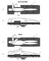
<<側臥位>>
図9(a)、(b)は、患者の身体を側臥位に固定した状態を示す。例えば、呼吸器外科の肺切除術は、患者の身体を側臥位に固定して行われる。患者の身体を側臥位に固定する場合は、テーブルトップ1の電動ウイング20A、20Bを、両方とも+90°近くまで回動させる。これにより、患者の身体は、電動ウイング20A、20Bによって正面側及び背面側から押えられる。電動ウイング20A、20Bを構成するマットレス52の面積が大きいので、患者の身体が局所的に圧迫されることがない。また、電動ウイング20A、20Bの角度を個別に調整することにより、患者の身体に加わる圧力を最適に調整することが可能である。<< Lateral position >>
FIGS. 9(a) and (b) show a state in which the patient's body is fixed in the lateral recumbent position. For example, pneumonectomy in respiratory surgery is performed with the patient's body fixed in a lateral recumbent position. When fixing the patient's body in the lateral recumbent position, the
さらに、電動ウイング20A、20Bの角度が+90°に近づくほど、テーブルトップ1の第2領域1B、すなわち、患者の開胸部付近に広い作業スペースが形成される。これにより、医者は、開胸部により接近して手術を行うことが可能となる。電動ウイング20A、20Bの回動によって形成される開胸部付近の作業スペースは、図5(b)の矢印で示す肩板10B、10Cの摺動によって、さらに拡張される。この結果、肺の手術において、肺の上葉、中葉、下葉に対応可能な広い作業スペースを確保することができる。 Furthermore, the closer the angle of the
<<半側臥位>>
図9(c)、(d)は、患者の身体を半側臥位に固定した状態を示す。半側臥位とは、患者を約45°の横向きに寝かせることをいう。例えば、消化器外科における胃癌食道浸潤例に対する左胸腹連続切開法は、患者の身体を半側臥位に固定して行われる。患者の身体を半側臥位に固定する場合は、テーブルトップ1の電動ウイング20A、20Bのうちのいずれか一方を+45°近くまで回動させる。これにより、患者の身体は、電動ウイング20A、20Bのいずれか一方によって、約45°の横向きに支持される。<<Half recumbent position>>
Figures 9(c) and (d) show the patient's body fixed in the semi-recumbent position. Semi-recumbent position refers to laying the patient on their side at approximately 45°. For example, in gastrointestinal surgery, continuous left thoracoabdominal incision for esophageal infiltration of gastric cancer is performed with the patient's body fixed in a semi-recumbent position. When fixing the patient's body in the semi-recumbent position, one of the
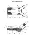
<<胸部を反らせた仰臥位>>
図10(a)、(b)は、患者の身体を胸部を反らせた仰臥位に固定した状態を示す。例えば、心臓外科における胸骨正中切開術は、患者の胸を反らせた仰臥位で行われる。患者の胸を反らせた状態にするためには、テーブルトップ1上で患者の身体を仰臥位にし、電動挙上器20Cを上昇させればよい。電動挙上器20Cは、最大60mmまで上昇させることができる。電動挙上器20Cを構成するマットレス52の面積が大きいので、患者の身体が局所的に圧迫されることがない。また、電動挙上器20Cの高さを精密に調整することにより、術野を最適化するとともに、患者の安楽を向上させることが可能である。<< supine position with chest bent >>
FIGS. 10(a) and 10(b) show a state in which the patient's body is fixed in a supine position with the chest curved. For example, a median sternotomy in cardiac surgery is performed with the patient in the supine position with the chest arched. In order to make the patient's chest arched, the patient's body should be placed in a supine position on the
<<仰臥位>>
図10(b)、(c)は、患者の身体を仰臥位に固定した状態を示す。仰臥位は、外科手術で最も一般的な体位である。患者の身体を仰臥位に固定する場合は、電動ウイング20A、20B及び電動挙上器20Cを動作させず、テーブルトップ1をフラットな状態にすればよい。<< supine position >>
FIGS. 10(b) and (c) show the patient's body fixed in the supine position. The supine position is the most common position in surgery. When the patient's body is fixed in the supine position, the
<<腹臥位>>
図11(a)、(b)は、患者の身体を腹臥位に固定した状態を示す。例えば、脊椎外科手術は、患者を腹臥位に固定して行われる。患者の身体を腹臥位に固定する場合も、電動ウイング20A、20B及び電動挙上器20Cを動作させず、テーブルトップ1をフラットな状態にすればよい。図11(a)、(b)に示すように、頭部と脚部の向きを前後方向に逆にして、患者の身体をテーブルトップ1上で腹臥位にしてもよい。<< prone position >>
Figures 11(a) and (b) show the patient's body fixed in the prone position. For example, spinal surgery is performed with the patient immobilized in a prone position. When the patient's body is fixed in the prone position, the
<<砕石位>>
図12(a)、(b)は、患者の身体を砕石位に固定した状態を示す。例えば、膀胱、前立腺、尿道、膣、子宮、肛門、直腸などの外科手術は、患者を砕石位に固定して行われる。患者の身体を砕石位に固定する場合は、テーブルトップ1から2つの脚板40A、40Bを両方とも取り外す。そして、腰板30を構成するフレーム51又はレール53に、一対の両支脚器70、70を取り付ける。第1~第3領域1A~1Cまでしかないテーブルトップ1上で患者の身体を仰臥位にし、患者の両脚を両支脚器70、70に固定する。これにより、患者の身体は砕石位に固定される。<< Crushed stone position >>
Figures 12(a) and (b) show the patient's body fixed in the lithotripsy position. For example, bladder, prostate, urethral, vaginal, uterine, anal, and rectal surgeries are performed with the patient fixed in a lithotripsy position. Both
<作用効果>
本実施形態のテーブルトップ1及び分離式手術台3によれば、アクセサリーを用いずに、胸部外科手術に好適な体位を容易に実現できる。第1に、電動ウイング20A、20Bは、テーブルトップ1の短手方向に手動で摺動させることができ、且つテーブルトップ1の上下方向に電動で回動させることが可能となっている。電動ウイング20A、20Bを摺動及び回動させることによって、患者の身体を容易に、側臥位又は半側臥位に固定することができる。第2に、電動挙上器20Cは、患者の胸部に対応する位置に昇降可能に設けられている。電動挙上器20Cを昇降させることによって、患者の身体を容易に、胸部を反らせた仰臥位に固定することができる。また、電動ウイング20A、20B及び電動挙上器20Cは、一旦固定した患者の体位を事後的に調整することも容易である。さらに、電動ウイング20A、20B又は電動挙上器20Cによって精密に調整された体位は、術野を最適化するとともに、患者の安楽を向上させる。<Effect>
According to the
本実施形態のテーブルトップ1及び分離式手術台3によれば、開胸部付近の作業スペースを拡張でき、医者が開胸部により接近して手術できる。電動ウイング20A、20Bの角度が+90°に近づくほど、テーブルトップ1の第2領域1B、すなわち、患者の開胸部付近に広い作業スペースが形成される。これにより、医者は、開胸部により接近して手術を行うことが可能となる。電動ウイング20A、20Bの回動によって形成される開胸部付近の作業スペースは、図5(b)の矢印で示す肩板10B、10Cの摺動によって、さらに拡張される。 According to the
1 テーブルトップ
1A 第1領域
1B 第2領域
1C 第3領域
1D 第4領域
2 コラム
2A 可動ヘッド
2B 上部ボディ
2C 下部ボディ
2D 基台
2E キャリア
3 手術台
10A 頭板
10B、10C 肩板
11 スライダ
12 スライド軸
20A、20B 電動ウイング
20C 電動挙上器
20D 背板
21 スライダ
22 スライドレール
23 回転軸
24 第1電気モータ
25 第2電気モータ
26 第3電気モータ
27 運動伝達機構
28 アーム
29 昇降板
29a ガイド軸
29b 軸受部
30 腰板
31 結合部
40A、40B 脚板
51 フレーム
52 マットレス
53 レール
61 結合部
62 操作部
63 ストッパ
64 車輪
70 両支脚器
Claims (6)
Translated fromJapanese前記患者の頭部及び肩部が載置される第1領域と、
前記患者の胸部及び腹部が載置される第2領域と、
前記患者の腰部が載置される第3領域と、
前記患者の脚部が載置される第4領域と、を含み、
前記第1領域は、中央と左右とに3分割され、前記第1領域の左右部分は、いずれも前記テーブルトップの長手方向に摺動可能に構成され、
前記第2領域は、中央と左右とに3分割され、前記第2領域の左右部分は、いずれも前記テーブルトップの短手方向に摺動可能、且つ前記テーブルトップの長手方向の軸を中心にして上下方向に回動することが可能に構成され、前記第2領域の中央部分は、前記胸部側と前記腹部側とに2分割され、前記胸部側の部分が昇降可能に構成される、
ことを特徴とするテーブルトップ。A table top for placing a patient undergoing surgery, comprising:
a first region on which the patient's head and shoulders rest;
a second region on which the patient's chest and abdomen rest;
a third region on which the patient's lower back rests;
a fourth area on which the patient's leg rests;
The first area is divided into three parts, the center and the left and right parts, and both the left and right parts of the first area are configured to be slidable in the longitudinal direction of the table top,
The second area is divided into three parts, the center and the left and right parts. Both the left and right parts of the second area are slidable in the lateral direction of the table top and centered on the longitudinal axis of the table top. The central part of the second region is divided into two parts, the chest side and the abdomen side, and the chest side part is configured to be able to move up and down.
A table top characterized by:
前記テーブルトップ及び前記コラムのそれぞれは、互いに着脱自在な結合部を備え、前記結合部を介して、前記コラムから前記テーブルトップに電源が供給されるように構成され、前記コラムは、操作部と、制御部と、駆動機構とをさらに備え、
前記操作部は、ユーザーによるコマンドの入力が可能となるように構成され、
前記制御部は、前記コマンドに基づいて、前記第1~第3電気モータ及び前記駆動機構の動作を制御し、
前記駆動機構は、前記結合部によって結合された前記テーブルトップの姿勢を上下方向、前後方向及び左右方向に変化させる、
ことを特徴とする分離式手術台。A detachable operating table comprising the table top according to claim 5 and a column capable of changing the posture of the table top, wherein the table top can be separated from the column,
Each of the table top and the column is provided with a mutually detachable coupling portion, and power is supplied from the column to the table top through the coupling portion, and the column is connected to an operation portion. , a control unit, and a drive mechanism,
The operation unit is configured to allow a user to input a command,
The control unit controls operations of the first to third electric motors and the drive mechanism based on the command,
The drive mechanism changes the posture of the table top coupled by the coupling portion in the vertical direction, the front-rear direction, and the left-right direction.
A separable operating table characterized by:
Priority Applications (1)
| Application Number | Priority Date | Filing Date | Title |
|---|---|---|---|
| JP2019005815AJP7170317B2 (en) | 2019-01-17 | 2019-01-17 | Tabletop and detachable operating table |
Applications Claiming Priority (1)
| Application Number | Priority Date | Filing Date | Title |
|---|---|---|---|
| JP2019005815AJP7170317B2 (en) | 2019-01-17 | 2019-01-17 | Tabletop and detachable operating table |
Publications (2)
| Publication Number | Publication Date |
|---|---|
| JP2020110517A JP2020110517A (en) | 2020-07-27 |
| JP7170317B2true JP7170317B2 (en) | 2022-11-14 |
Family
ID=71666158
Family Applications (1)
| Application Number | Title | Priority Date | Filing Date |
|---|---|---|---|
| JP2019005815AActiveJP7170317B2 (en) | 2019-01-17 | 2019-01-17 | Tabletop and detachable operating table |
Country Status (1)
| Country | Link |
|---|---|
| JP (1) | JP7170317B2 (en) |
Citations (5)
| Publication number | Priority date | Publication date | Assignee | Title |
|---|---|---|---|---|
| JP2001522649A (en) | 1997-11-07 | 2001-11-20 | ヒル−ロム,インコーポレイティド | Operating table equipment |
| JP2002126017A (en) | 2000-10-26 | 2002-05-08 | Katsutoshi Naruse | Operating table |
| US20030167569A1 (en) | 2002-03-11 | 2003-09-11 | Newkirk David C. | Surgical table having integral lateral supports |
| JP2007136179A (en) | 2005-11-14 | 2007-06-07 | Maquet Gmbh & Co Kg | Device for adjusting operating table |
| US20130086747A1 (en) | 2011-10-07 | 2013-04-11 | Gharieni Gmbh | Treatment couch |
- 2019
- 2019-01-17JPJP2019005815Apatent/JP7170317B2/enactiveActive
Patent Citations (5)
| Publication number | Priority date | Publication date | Assignee | Title |
|---|---|---|---|---|
| JP2001522649A (en) | 1997-11-07 | 2001-11-20 | ヒル−ロム,インコーポレイティド | Operating table equipment |
| JP2002126017A (en) | 2000-10-26 | 2002-05-08 | Katsutoshi Naruse | Operating table |
| US20030167569A1 (en) | 2002-03-11 | 2003-09-11 | Newkirk David C. | Surgical table having integral lateral supports |
| JP2007136179A (en) | 2005-11-14 | 2007-06-07 | Maquet Gmbh & Co Kg | Device for adjusting operating table |
| US20130086747A1 (en) | 2011-10-07 | 2013-04-11 | Gharieni Gmbh | Treatment couch |
Also Published As
| Publication number | Publication date |
|---|---|
| JP2020110517A (en) | 2020-07-27 |
Similar Documents
| Publication | Publication Date | Title |
|---|---|---|
| US20210353487A1 (en) | Surgical patient support for lateral-to-prone patient positioning | |
| US12186243B2 (en) | Surgical frame having translating lower beam and method for use thereof | |
| JP5323850B2 (en) | Operating table device | |
| US10888484B2 (en) | Reconfigurable pelvic support for surgical frame and method for use thereof | |
| US11369538B2 (en) | Reconfigurable pelvic support for a surgical frame and method for use thereof | |
| US8336142B1 (en) | Body and head support | |
| US8615827B2 (en) | Person-support apparatus with movable portions | |
| US10881567B2 (en) | Patient support apparatus | |
| EP1350449A1 (en) | Adjustable profiling beds | |
| KR100979585B1 (en) | Treatment table | |
| JP2020185417A (en) | Prone and lateral surgical table | |
| CN213311299U (en) | Treatment bed capable of realizing lumbar decompression and spine correction | |
| CN103784308A (en) | Multi-position treatment couch | |
| EP2777671A1 (en) | Patient table | |
| CN107847381B (en) | electric bed | |
| CN114288139A (en) | Neural inspection device of shank for department of neurology | |
| KR20130101285A (en) | Table for physiotherapy | |
| JP7170317B2 (en) | Tabletop and detachable operating table | |
| CN203710347U (en) | Multi-body-position treatment bed | |
| EP0705091B1 (en) | Intensive therapy bed | |
| CN219049270U (en) | Massage bed equipment | |
| CN112120879A (en) | Electric obstetric table for obstetrical department | |
| RU2348391C1 (en) | Tilting medical bed | |
| CN219230449U (en) | Improved orthopedic nursing bed | |
| CN221787174U (en) | A body position cushion with adjustable curvature |
Legal Events
| Date | Code | Title | Description |
|---|---|---|---|
| A80 | Written request to apply exceptions to lack of novelty of invention | Free format text:JAPANESE INTERMEDIATE CODE: A80 Effective date:20190201 | |
| A621 | Written request for application examination | Free format text:JAPANESE INTERMEDIATE CODE: A621 Effective date:20211013 | |
| TRDD | Decision of grant or rejection written | ||
| A977 | Report on retrieval | Free format text:JAPANESE INTERMEDIATE CODE: A971007 Effective date:20220916 | |
| A01 | Written decision to grant a patent or to grant a registration (utility model) | Free format text:JAPANESE INTERMEDIATE CODE: A01 Effective date:20220927 | |
| A61 | First payment of annual fees (during grant procedure) | Free format text:JAPANESE INTERMEDIATE CODE: A61 Effective date:20221025 | |
| R150 | Certificate of patent or registration of utility model | Ref document number:7170317 Country of ref document:JP Free format text:JAPANESE INTERMEDIATE CODE: R150 |