JP7170127B2 - Loading system and associated loading method for implantable prostheses - Google Patents
Loading system and associated loading method for implantable prosthesesDownload PDFInfo
- Publication number
- JP7170127B2 JP7170127B2JP2021515295AJP2021515295AJP7170127B2JP 7170127 B2JP7170127 B2JP 7170127B2JP 2021515295 AJP2021515295 AJP 2021515295AJP 2021515295 AJP2021515295 AJP 2021515295AJP 7170127 B2JP7170127 B2JP 7170127B2
- Authority
- JP
- Japan
- Prior art keywords
- receiver
- heart valve
- axial position
- gripper
- valve prosthesis
- Prior art date
- Legal status (The legal status is an assumption and is not a legal conclusion. Google has not performed a legal analysis and makes no representation as to the accuracy of the status listed.)
- Active
Links
- 238000011068loading methodMethods0.000titleclaimsdescription112
- 210000003709heart valveAnatomy0.000claimsdescription121
- 230000008878couplingEffects0.000claimsdescription32
- 238000010168coupling processMethods0.000claimsdescription32
- 238000005859coupling reactionMethods0.000claimsdescription32
- 238000006073displacement reactionMethods0.000claimsdescription26
- 238000000034methodMethods0.000claimsdescription24
- 230000008602contractionEffects0.000claimsdescription9
- 230000009471actionEffects0.000claimsdescription8
- 238000003860storageMethods0.000claimsdescription5
- 230000003068static effectEffects0.000claimsdescription4
- 230000007704transitionEffects0.000claimsdescription4
- 230000013011matingEffects0.000claimsdescription3
- 230000015572biosynthetic processEffects0.000description15
- 238000005755formation reactionMethods0.000description15
- 238000007789sealingMethods0.000description8
- 230000007246mechanismEffects0.000description6
- 238000002513implantationMethods0.000description5
- 239000000243solutionSubstances0.000description5
- 230000017531blood circulationEffects0.000description4
- 230000004048modificationEffects0.000description4
- 238000012986modificationMethods0.000description4
- 230000035515penetrationEffects0.000description3
- 210000001765aortic valveAnatomy0.000description2
- 230000004323axial lengthEffects0.000description2
- 238000002788crimpingMethods0.000description2
- 238000004519manufacturing processMethods0.000description2
- 238000003032molecular dockingMethods0.000description2
- 238000001356surgical procedureMethods0.000description2
- QNRATNLHPGXHMA-XZHTYLCXSA-N(r)-(6-ethoxyquinolin-4-yl)-[(2s,4s,5r)-5-ethyl-1-azabicyclo[2.2.2]octan-2-yl]methanol;hydrochlorideChemical classCl.C([C@H]([C@H](C1)CC)C2)CN1[C@@H]2[C@H](O)C1=CC=NC2=CC=C(OCC)C=C21QNRATNLHPGXHMA-XZHTYLCXSA-N0.000description1
- 239000008186active pharmaceutical agentSubstances0.000description1
- 238000007792additionMethods0.000description1
- 238000006664bond formation reactionMethods0.000description1
- 238000010586diagramMethods0.000description1
- 239000010432diamondSubstances0.000description1
- 238000009826distributionMethods0.000description1
- 230000004927fusionEffects0.000description1
- 238000009434installationMethods0.000description1
- 230000003993interactionEffects0.000description1
- 230000000670limiting effectEffects0.000description1
- 230000036316preloadEffects0.000description1
- 230000008569processEffects0.000description1
- 230000009467reductionEffects0.000description1
- 230000000452restraining effectEffects0.000description1
- 230000000717retained effectEffects0.000description1
- 230000002441reversible effectEffects0.000description1
- 125000006850spacer groupChemical group0.000description1
- 239000008174sterile solutionSubstances0.000description1
- 238000011477surgical interventionMethods0.000description1
- 230000002792vascularEffects0.000description1
Images


Classifications
- A—HUMAN NECESSITIES
- A61—MEDICAL OR VETERINARY SCIENCE; HYGIENE
- A61F—FILTERS IMPLANTABLE INTO BLOOD VESSELS; PROSTHESES; DEVICES PROVIDING PATENCY TO, OR PREVENTING COLLAPSING OF, TUBULAR STRUCTURES OF THE BODY, e.g. STENTS; ORTHOPAEDIC, NURSING OR CONTRACEPTIVE DEVICES; FOMENTATION; TREATMENT OR PROTECTION OF EYES OR EARS; BANDAGES, DRESSINGS OR ABSORBENT PADS; FIRST-AID KITS
- A61F2/00—Filters implantable into blood vessels; Prostheses, i.e. artificial substitutes or replacements for parts of the body; Appliances for connecting them with the body; Devices providing patency to, or preventing collapsing of, tubular structures of the body, e.g. stents
- A61F2/0095—Packages or dispensers for prostheses or other implants
- A—HUMAN NECESSITIES
- A61—MEDICAL OR VETERINARY SCIENCE; HYGIENE
- A61F—FILTERS IMPLANTABLE INTO BLOOD VESSELS; PROSTHESES; DEVICES PROVIDING PATENCY TO, OR PREVENTING COLLAPSING OF, TUBULAR STRUCTURES OF THE BODY, e.g. STENTS; ORTHOPAEDIC, NURSING OR CONTRACEPTIVE DEVICES; FOMENTATION; TREATMENT OR PROTECTION OF EYES OR EARS; BANDAGES, DRESSINGS OR ABSORBENT PADS; FIRST-AID KITS
- A61F2/00—Filters implantable into blood vessels; Prostheses, i.e. artificial substitutes or replacements for parts of the body; Appliances for connecting them with the body; Devices providing patency to, or preventing collapsing of, tubular structures of the body, e.g. stents
- A61F2/02—Prostheses implantable into the body
- A61F2/24—Heart valves ; Vascular valves, e.g. venous valves; Heart implants, e.g. passive devices for improving the function of the native valve or the heart muscle; Transmyocardial revascularisation [TMR] devices; Valves implantable in the body
- A61F2/2427—Devices for manipulating or deploying heart valves during implantation
- A61F2/2436—Deployment by retracting a sheath
- A—HUMAN NECESSITIES
- A61—MEDICAL OR VETERINARY SCIENCE; HYGIENE
- A61F—FILTERS IMPLANTABLE INTO BLOOD VESSELS; PROSTHESES; DEVICES PROVIDING PATENCY TO, OR PREVENTING COLLAPSING OF, TUBULAR STRUCTURES OF THE BODY, e.g. STENTS; ORTHOPAEDIC, NURSING OR CONTRACEPTIVE DEVICES; FOMENTATION; TREATMENT OR PROTECTION OF EYES OR EARS; BANDAGES, DRESSINGS OR ABSORBENT PADS; FIRST-AID KITS
- A61F2/00—Filters implantable into blood vessels; Prostheses, i.e. artificial substitutes or replacements for parts of the body; Appliances for connecting them with the body; Devices providing patency to, or preventing collapsing of, tubular structures of the body, e.g. stents
- A61F2/95—Instruments specially adapted for placement or removal of stents or stent-grafts
- A61F2/9522—Means for mounting a stent or stent-graft onto or into a placement instrument
- A61F2/9525—Means for mounting a stent or stent-graft onto or into a placement instrument using a funnel
Landscapes
- Health & Medical Sciences (AREA)
- Cardiology (AREA)
- Engineering & Computer Science (AREA)
- Biomedical Technology (AREA)
- Heart & Thoracic Surgery (AREA)
- Transplantation (AREA)
- Oral & Maxillofacial Surgery (AREA)
- Vascular Medicine (AREA)
- Life Sciences & Earth Sciences (AREA)
- Animal Behavior & Ethology (AREA)
- General Health & Medical Sciences (AREA)
- Public Health (AREA)
- Veterinary Medicine (AREA)
- Prostheses (AREA)
Description
Translated fromJapanese本開示は、移植可能なプロテーゼローディングシステムおよび方法、特に、径方向に収縮可能なアーマチュアおよびアーマチュアによって支持される心臓弁プロテーゼを含む心臓弁プロテーゼのための移植可能なプロテーゼローディングシステムに言及する。 The present disclosure refers to implantable prosthesis loading systems and methods, particularly implantable prosthesis loading systems for heart valve prostheses including radially contractible armatures and heart valve prostheses supported by armatures.
心臓弁手術および介入性心臓病学の分野では、血管プロテーゼや心臓弁プロテーゼなどの移植可能なプロテーゼの取り扱いの容易さ、および外科的介入および処置を行うのに必要な時間の短縮が、本分野の医療および技術研究の主題である。 In the field of heart valve surgery and interventional cardiology, the ease of handling of implantable prostheses, such as vascular prostheses and heart valve prostheses, and the reduction in the time required to perform surgical interventions and procedures are of interest in this field. is the subject of medical and technical research.
例えば、無縫合弁プロテーゼなどの拡張可能な心臓弁プロテーゼの移植に関して、現行のプラクティスは、心臓弁プロテーゼがその完全性を維持するために無菌環境に格納されるべきであると規定している。 For example, regarding the implantation of expandable heart valve prostheses, such as sutureless valve prostheses, current practice dictates that the heart valve prosthesis should be stored in a sterile environment to maintain its integrity.
移植可能な心臓弁プロテーゼを送達器具にローディングするには、いくつか重要な問題が存在し得る。圧着操作を容易にするために、異なる特徴を有する多くの圧着装置が考案されてきたが、そのようなステップは、行うのがかなり難しく、複雑なままであることがある。 Loading an implantable heart valve prosthesis onto a delivery device can present several significant challenges. Although many crimping devices with different features have been devised to facilitate the crimping operation, such steps can remain rather difficult and complicated to perform.
心臓弁プロテーゼを送達器具にローディングするときに医師にとって主要な課題の1つは、格納設備(通常、保存用の滅菌溶液で満たされたいわゆる「ジャー」)から送達器具へのプロテーゼの取り扱いである。様々な現行の解決策は、複数の取り扱いデバイスまたは弁の手動操作のいずれかを必要とし、これらは両方とも、実際には送達器具への容易で完璧な弁のローディングへの期待の下では望ましくない。 One of the major challenges for physicians when loading a heart valve prosthesis into a delivery device is the handling of the prosthesis from its containment facility (usually a so-called "jar" filled with sterile solution for storage) to the delivery device. . Various current solutions require either multiple handling devices or manual manipulation of the valve, both of which are actually desirable given the expectation of easy and complete loading of the valve into the delivery device. do not have.
実施形態では、上記の課題は、既知のシステムと比較して、移植可能な心臓弁プロテーゼの送達器具へのローディングをより容易に、より安全に、より速く、より正確にするシステムを提供することによって達成され得る。 In embodiments, the above problem is to provide a system that makes loading an implantable heart valve prosthesis onto a delivery device easier, safer, faster and more accurate than known systems. can be achieved by
第1の例では、径方向に収縮可能なアーマチュアと、アーマチュアに結合された人工心臓弁と、を含む心臓弁プロテーゼのためのローディングシステムであって、アーマチュアが、少なくとも1つの径方向に収縮可能な環状部分を有し、ローディングシステムは、
ローディングシステムの長手方向軸に沿って、第1の軸方向位置から第2の軸方向位置まで軸方向に動作可能なグリッパーであって、第1の軸方向位置において、グリッパーは、アーマチュアが径方向に拡張した状態で、心臓弁プロテーゼに係合する、グリッパーと、
心臓弁プロテーゼのための第1のレシーバであって、第1のレシーバが、心臓弁プロテーゼによる第1のレシーバの係合時に、心臓弁プロテーゼの少なくとも第1の部分を径方向に収縮した状態で保持するように構成されており、グリッパーが、第1のレシーバに対して軸方向に変位可能である、第1のレシーバと、
第1のレシーバを取り囲む第1の漏斗形状要素であって、第1の漏斗形状要素が、第1の直径および第2の直径を有し、第2の直径が、第1の直径よりも小さく、第1の直径よりも第1のレシーバに軸方向に近く配置され、グリッパーは、第1の漏斗形状要素に対して軸方向に変位可能である、第1の漏斗形状要素と、を含み、
第1の軸方向位置から第2の軸方向位置への移行において、グリッパーは、第1の直径から第2の直径まで第1の漏斗形状要素を通して心臓弁プロテーゼを軸方向に変位させるように構成されており、それにより、第2の軸方向位置への到達時に、心臓弁プロテーゼのアーマチュアを径方向に収縮させ、かつ径方向に収縮した状態でレシーバ少なくとも第1の部分を第1のレシーバ内へ適合させる。In a first example, a loading system for a heart valve prosthesis comprising a radially contractible armature and a prosthetic heart valve coupled to the armature, wherein the armature is at least one radially contractible having an annular portion, the loading system comprising:
A gripper axially operable from a first axial position to a second axial position along a longitudinal axis of the loading system, wherein at the first axial position the gripper has an armature radially extending from the a gripper for engaging the heart valve prosthesis in an expanded state;
A first receiver for a heart valve prosthesis, the first receiver radially contracting at least a first portion of the heart valve prosthesis upon engagement of the first receiver by the heart valve prosthesis. a first receiver configured to hold, wherein the gripper is axially displaceable relative to the first receiver;
A first funnel-shaped element surrounding the first receiver, the first funnel-shaped element having a first diameter and a second diameter, the second diameter being smaller than the first diameter , a first funnel-shaped element disposed axially closer to the first receiver than the first diameter, the gripper being axially displaceable relative to the first funnel-shaped element;
In transitioning from the first axial position to the second axial position, the gripper is configured to axially displace the heart valve prosthesis through the first funnel-shaped element from the first diameter to the second diameter. thereby radially contracting the armature of the heart valve prosthesis upon reaching the second axial position and, in a radially contracted state, moving the receiver at least the first portion into the first receiver. adapt to
第1の例に従う第2の例は、グリッパーに対して軸方向に固定された管状部材を含み、管状部材は、第1のレシーバが嵌合するホルダーを含む。 A second example following the first example includes a tubular member axially fixed to the gripper, the tubular member including a holder in which the first receiver fits.
第2の例に従う第3の例では、グリッパーは、管状部材によって包まれたスタッドと、スタッドの一端にある把持部分と、を含み、管状部材は、スタッドと係合する駆動部材をさらに含み、駆動部材が動作すると、スタッドを軸方向に変位させ、把持部分は、第1の軸方向位置において、心臓弁プロテーゼの少なくとも第1の部分の結合要素と係合する。 In a third example following the second example, the gripper includes a stud encased by a tubular member and a gripping portion at one end of the stud, the tubular member further including a drive member engaging the stud, Actuation of the drive member axially displaces the stud such that the gripping portion engages a coupling element of at least a first portion of the heart valve prosthesis in a first axial position.
第3の例に従う第4の例では、スタッドには、ねじ山がついており、駆動部材は、スタッドのねじ山に係合するねじ山つき回転駆動部材である。 In a fourth example following the third example, the stud is threaded and the drive member is a threaded rotary drive member engaging the thread of the stud.
第2の例または第3の例に従う第5の例では、スタッドは、中空スタッドであり、軸方向スロットを含み、ホルダーは、管状部材内で、長手方向軸に沿って軸方向に、かつこれに対して同軸に延在し、中空スタッドは、ホルダーの周りにスライド可能に適合し、軸方向スロットはホルダーを管状部材に接続する架橋部材を収容する。 In a fifth example according to the second or third example, the stud is a hollow stud and includes an axial slot, the holder axially along the longitudinal axis and within the tubular member. A hollow stud slidably fits around the holder and an axial slot accommodates a bridging member connecting the holder to the tubular member.
前述の請求項のいずれかに従う第6の例では、グリッパーは、複数の弾性フィンガー部材を備える把持部分を含み、弾性フィンガー部材は、心臓弁プロテーゼの径方向外向きに心臓弁プロテーゼと係合し、グリッパーが第1の漏斗形状要素に対して第1の軸方向位置から第2の軸方向位置まで軸方向に変位すると、径方向分岐状態から径方向折り畳み状態に径方向に変位可能であり、それにより、心臓弁プロテーゼのアーマチュアを径方向に収縮させる。 In a sixth example according to any of the preceding claims, the gripper comprises a gripping portion comprising a plurality of resilient finger members, the resilient finger members engaging the heart valve prosthesis radially outwardly of the heart valve prosthesis. , is radially displaceable from a radially diverging state to a radially folded state when the gripper is axially displaced relative to the first funnel-shaped element from a first axial position to a second axial position; This radially contracts the armature of the heart valve prosthesis.
第6の例に従う第7の例では、各弾性フィンガーはガイドブレードに関連付けられ、各ガイドブレードは、弾性フィンガーが径方向分岐状態から径方向折り畳み状態に変位している間、弾性フィンガーを収容するように構成されている長手方向貫通スロットを含み、それにより、弾性フィンガーを長手方向に沿って整列させたままにする。 In a seventh example following the sixth example, each resilient finger is associated with a guide blade, each guide blade accommodating the resilient finger during its displacement from the radially diverging state to the radially collapsed state. to keep the resilient fingers aligned along the length.
前述の請求項のいずれかに従う第8の例では、第1の漏斗形状要素は、第1のレシーバに取り外し可能に結合されている。 In an eighth example according to any of the preceding claims, the first funnel-shaped element is removably coupled to the first receiver.
前述の請求項のいずれかに従う第9の例は、心臓弁プロテーゼのための送達器具であって、シャフトと、シャフトに結合されたハブと、ハブに対して第3の軸方向位置から第4の軸方向位置まで軸方向にスライド可能な第2のレシーバと、を含む、送達器具を含み、
送達器具のハブは、第1のレシーバと結合するように構成されており、
第2のレシーバは、それに結合された第2の漏斗形状要素を含み、第2の漏斗形状要素は、第3の直径および第4の直径を有し、第4の直径は、第3の直径よりも小さく、第3の直径よりも第2のレシーバに軸方向に近く、第3の直径は、グリッパーに結合された心臓弁プロテーゼとともに提示され、
第3の軸方向位置から第4の軸方向位置までの第2のレシーバの軸方向変位において、第2の漏斗形状要素が、心臓弁プロテーゼに対して移動することで、アーマチュアの第2の部分が、第3の直径から第4の直径まで狭まる管腔を通り抜け、径方向に収縮した状態で第2のレシーバ内に適合する。A ninth example according to any of the preceding claims is a delivery device for a heart valve prosthesis, comprising a shaft, a hub coupled to the shaft, and a shaft extending from a third axial position to a fourth axial position relative to the hub. a second receiver axially slidable to an axial position of
a hub of the delivery device configured to mate with the first receiver;
The second receiver includes a second funnel-shaped element coupled thereto, the second funnel-shaped element having a third diameter and a fourth diameter, the fourth diameter being the third diameter smaller than and axially closer to the second receiver than the third diameter, the third diameter being presented with the heart valve prosthesis coupled to the gripper;
Upon axial displacement of the second receiver from the third axial position to the fourth axial position, the second funnel-shaped element moves relative to the heart valve prosthesis to move the second portion of the armature. passes through a lumen that narrows from a third diameter to a fourth diameter and fits within the second receiver in a radially contracted state.
第9の例に従う第10の例では、第2の漏斗形状要素は、第2のレシーバに取り外し可能に結合されている。 In a tenth example according to the ninth example, the second funnel-shaped element is removably coupled to the second receiver.
第2の例または第10の例に従う第11の例では、第1のレシーバは、ホルダーに取り外し可能に結合されている。 In an eleventh example according to the second or tenth example, the first receiver is detachably coupled to the holder.
第1の例に従う第12の例では、レシーバ、グリッパー、およびそれらに取り付けられた心臓弁プロテーゼは、保存溶液で満たされたジャーに格納され、第1の漏斗形状要素は、第1のレシーバに事前に装着されている。 In a twelfth example according to the first example, the receiver, the gripper and the heart valve prosthesis attached to them are stored in a jar filled with a storage solution and the first funnel-shaped element is attached to the first receiver. pre-fitted.
第1の例または第12の例に従う第13の例では、ローディングシステムは、径方向に収縮可能なアーマチュアと、アーマチュアによって支持される人工心臓弁と、を含む心臓弁プロテーゼをさらに含み、アーマチュアは、少なくとも1つの径方向に収縮可能な環状部分を有し、第1の軸方向位置において、グリッパーは、アーマチュアが径方向に拡張した状態で、心臓弁プロテーゼに係合する。 In a thirteenth example according to the first example or the twelfth example, the loading system further comprises a heart valve prosthesis including a radially contractible armature and an artificial heart valve supported by the armature, the armature , at least one radially contractible annular portion, and in a first axial position the gripper engages the heart valve prosthesis with the armature radially expanded.
第14の例は、前述の例のいずれかによるローディングシステムを使用して、人工心臓弁を送達器具にローディングする方法であり、その方法は、
グリッパーを第1の軸方向位置から第2の軸方向位置まで変位させて、心臓弁プロテーゼの少なくとも1つの部分を径方向に折り畳まれた状態で、第1のレシーバ内に適合させることと、
第1の漏斗形状要素をローディングシステムから分離することと、
第1のレシーバを送達器具のハブに結合することと、
第2のレシーバを第3の軸方向位置から第4の軸方向位置に変位させて、心臓弁プロテーゼの第2の部分を径方向に折り畳まれた状態で、第2のレシーバ内に適合させることと、
第2の漏斗形状要素を送達器具から分離することと、
第1のレシーバが送達器具のハブに取り付けられた状態を維持しながら、第1のレシーバをホルダーから分離することと、を含む。A fourteenth example is a method of loading a prosthetic heart valve onto a delivery device using a loading system according to any of the preceding examples, the method comprising:
displacing the gripper from the first axial position to the second axial position to fit at least one portion of the heart valve prosthesis in a radially collapsed state within the first receiver;
separating the first funnel-shaped element from the loading system;
coupling the first receiver to the hub of the delivery device;
Displacing the second receiver from the third axial position to the fourth axial position to fit the second portion of the heart valve prosthesis in the radially collapsed state within the second receiver. When,
separating the second funnel-shaped element from the delivery device;
separating the first receiver from the holder while maintaining the first receiver attached to the hub of the delivery device.
第14の例に従う第15の例では、第1のレシーバをホルダーから分離することは、プロテーゼの少なくとも一部分が第1のレシーバにローディングされた状態で、グリッパーを第1の軸方向位置に向けて戻すように軸方向に変位させて、プロテーゼからグリッパーを解放することを含む。 In a fifteenth example according to the fourteenth example, separating the first receiver from the holder comprises orienting the gripper to the first axial position with at least a portion of the prosthesis loaded in the first receiver. Axial displacement back to release the gripper from the prosthesis.
第15の例に従う第16の例では、第2の軸方向位置において、弾性フィンガーは、第1のレシーバの軸方向外側に位置し、管状部材によって径方向に収縮した状態に保持され、グリッパーを第1の軸方向位置に向けて戻すように軸方向に変位させることは、管状部材の径方向の収縮作用から弾性フィンガーを解放し、それにより、結合要素に対する弾性フィンガーの径方向外向きの運動によって、弾性フィンガーを心臓弁プロテーゼの少なくとも第1の部分の結合要素から解放する。 In a sixteenth example according to the fifteenth example, in the second axial position the resilient finger is located axially outward of the first receiver and is held in a radially contracted state by the tubular member to hold the gripper. Axial displacement back toward the first axial position releases the resilient fingers from the radial contraction action of the tubular member, thereby causing radial outward movement of the resilient fingers relative to the coupling element. releases the resilient finger from the coupling element of the at least first portion of the heart valve prosthesis.
第17の例は、第1の例~第13の例までのいずれかによるローディングシステムを使用して、人工心臓弁を送達器具にローディングする方法であり、その方法は、
グリッパーを第1の軸方向位置から第2の軸方向位置に変位させて、心臓弁プロテーゼを径方向に折り畳まれた状態で第1のレシーバ内に適合させることと、
第1の漏斗形状要素をローディングシステムから分離することと、
第1のレシーバを取り外し、第1のレシーバを送達器具に結合することと、を含む。A seventeenth example is a method of loading a prosthetic heart valve onto a delivery device using a loading system according to any of the first through thirteenth examples, the method comprising:
displacing the gripper from the first axial position to the second axial position to fit the heart valve prosthesis in the radially collapsed state within the first receiver;
separating the first funnel-shaped element from the loading system;
removing the first receiver and coupling the first receiver to the delivery device.
第17の例に従う第18の例では、第1のレシーバは、送達シースとして長さが延長され、かつハブに対して軸方向にスライド可能である環状部分を含み、長さが延長された環状部分は、プロテーゼの軸方向延長部を覆うように構成されている。 In an eighteenth example according to the seventeenth example, the first receiver includes an annular portion elongated in length as the delivery sheath and axially slidable relative to the hub, the elongated annular portion The portion is configured to cover the axial extension of the prosthesis.
第18の例に従う第19の例では、環状部分は、送達器具の軸方向変位のために送達器具の作動部材と嵌合することを意図されており、ハブは、送達器具のシャフトの静的部分と嵌合することを意図されている。 In a nineteenth example following the eighteenth example, the annular portion is intended to mate with the actuating member of the delivery device for axial displacement of the delivery device, and the hub is a static displacement of the shaft of the delivery device. intended to mate with parts.
複数の実施形態が開示されているが、本開示のさらに他の実施形態は、本開示の例示的な実施形態を示し、説明する以下の詳細な説明から当業者には明らかになるであろう。したがって、図面および詳細な説明は、本質的に例示と見なされるべきであり、限定と見なされるべきではない。 While multiple embodiments are disclosed, still other embodiments of the present disclosure will become apparent to those skilled in the art from the following detailed description, which shows and describes exemplary embodiments of the present disclosure. . Accordingly, the drawings and detailed description are to be considered illustrative in nature and not restrictive.
ここで、本明細書の様々な実施形態を、純粋に非限定的な例として提供される添付の図を参照して説明する。 Various embodiments herein will now be described with reference to the accompanying figures, which are provided purely as non-limiting examples.
本開示は、様々な修正形態および代替形態が可能であるが、特定の実施形態が、例として図面に示され、以下で詳細に説明される。しかしながら、その意図は、説明された実施形態に開示を限定することではない。それどころか、本開示は、特許請求の範囲によって定義される本開示の範囲内にあるすべての修正物、等価物、および代替物を網羅することを意図している。 While the disclosure is susceptible to various modifications and alternative forms, specific embodiments are shown by way of example in the drawings and will be described in detail below. The intention, however, is not to limit the disclosure to the described embodiments. On the contrary, this disclosure is intended to cover all modifications, equivalents, and alternatives falling within the scope of this disclosure as defined by the claims.
図1の参照番号1は、本開示の実施形態による、心臓弁プロテーゼのためのローディングシステムを示す。
本明細書で説明される実施形態において、図1、図2A、図2B、および図3Aを参照すると、ローディングシステム1は、
径方向に収縮可能なアーマチュアと、アーマチュアに結合された人工心臓弁と、を含む心臓弁プロテーゼ2であって、アーマチュアは、少なくとも1つの径方向に収縮可能な環状部分を有する、心臓弁プロテーゼ2と、
ローディングシステム1の長手方向軸X1に沿って、第1の軸方向位置から第2の軸方向位置まで軸方向に動作可能なグリッパー3であって、第1の軸方向位置において、グリッパー3は、アーマチュアが径方向に拡張した状態で、心臓弁プロテーゼ2に係合する、グリッパー3と、
心臓弁プロテーゼ2のための第1のレシーバ4であって、第1のレシーバ4は、心臓弁プロテーゼによる第1のレシーバの係合時に、心臓弁プロテーゼ2の第1の部分、好ましくは径方向に収縮可能な環状部分を径方向に収縮した状態で保持するように構成されており、グリッパー3は、第1のレシーバ4に対して軸方向に変位可能である、第1のレシーバ4と、
第1のレシーバ4を取り囲む第1の漏斗形状要素5であって、第1の漏斗形状要素5は、第1の直径D1および第2の直径D2を有し、第2の直径は、第1の直径よりも小さく、第1の直径D1よりも第1のレシーバ4に軸方向に近く配置され、グリッパー3は、第1の漏斗形状要素5に対して軸方向に変位可能である、第1の漏斗形状要素5と、を含み得る。In the embodiments described herein, referring to FIGS. 1, 2A, 2B and 3A, the loading system 1:
A
A
A
A first funnel-shaped
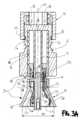
図2Bおよび図3Aを参照すると、いくつかの実施形態では、ローディングシステム1は、グリッパー(またはその一部)の外殻を少なくとも部分的に規定し得る管状部材6、およびグリッパーの駆動部材のアタッチメントを含む。管状部材6は、グリッパーに対して軸方向に固定され、グリッパーは、それに対して軸方向に移動する。 2B and 3A, in some embodiments, the
管状部材6は、軸X1に沿って長手方向、および軸X1と同軸に延在するホルダー7を含むことができる。ホルダー7は、第1のレシーバ4のカップリングシートとして構成されている。いくつかの実施形態では、図示されるように、ホルダー7は、軸X1と同軸のハブ9から径方向に延在する架橋形成部8によって管状部材6内に吊り下げられ、管状部材6によって囲まれた管状部材である。いくつかの実施形態では、ハブ9なしで、管状部材の内壁を横切って延在する単一の架橋形成部が提供される。
実施形態では、グリッパー3は、管状部材6によって包まれたスタッド10(図3Aおよび図3C)と、スタッド10の一端にある把持部分11とを含む。図3Aに示される第1の軸方向位置では、把持部分11は、本質的に、第1の漏斗形状要素5に対応する軸方向位置に配置されている。 In an embodiment,
実施形態では、駆動部材12は、スタッド10と係合して、駆動部材の動作時にスタッド10を軸方向に変位させる。いくつかの実施形態では、駆動部材12は、把持部分が配置されている端部の反対側の管状部材6の一端で管状部材6と係合する回転ノブである。図3Aに示されるように、係合は、弾性構造13(回転ノブ12の本体に片持ち梁式に固定されている)が管状部材6の外面に提供された環状溝Gに係合することによって起きてもよい。 In embodiments, the
実施形態では、回転ノブ12は、スタッドの外面上の外ねじ16と係合する内ねじ15を含み、回転ノブの回転動作が、スタッド、およびグリッパー全体の軸X1に沿った軸方向の運動をもたらすようにする。 In an embodiment, the
代替的には、いくつかの実施形態では、別の種類のカム機構、例えば、駆動部材12およびスタッド10のいずれかに提供されるカムトラックと、その2つのうちの他方に提供されるピン(複数可)/カムフォロア(複数可)とのカムピンの係合が、駆動部材12とグリッパー3との間に提供されてもよい。 Alternatively, in some embodiments, another type of cam mechanism is provided, e.g., a cam track provided on one of the
図3Aおよび図3Cを参照すると、図に示されるような実施形態では、スタッド10は中空スタッドであり、その外面にねじ16(または必要に応じて、カムトラック/カムフォロア)を支持することができる2つの半円筒形軸方向部分18を分離する軸方向スロット17を含む。軸方向スロット17は、環状部分19で終端し、2つの軸方向延長部18が合流する。 3A and 3C, in the embodiment as shown,
スタッド10のこの設計は、グリッパー3が管状部材6に軸方向に挿入されたときに、スタッド10とホルダー7との間の貫通を可能にする。具体的には、中空スタッド10は、ホルダー7の周りにスライド可能に取り付けられ、それによって、ホルダー7をスタッド10内および軸方向延長部18間に収容する一方で、軸方向スロット17は、ホルダー7を管状部材6に接続するブリッジ架橋形成部(または一般に架橋部材)を収容する。 This design of
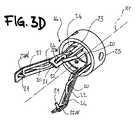
図3Dを参照すると、図のような実施形態では、把持部分14は、把持部分に結合された心臓弁プロテーゼ2の特定の特徴に依存し得る数の複数の弾性フィンガー20で構成される弾性フィンガー部材を含む。後続の図4Aに見られるような大動脈弁プロテーゼの係合に適しているいくつかの実施形態では、弾性フィンガー20は、3つあり、120度の間隔で離間している。フィンガー20の各々は、第1の漏斗形状要素5に対して第1の軸方向位置から第2の軸方向までグリッパー3が軸方向に変位すると、径方向に分岐した状態(図3Aおよび図3Dに見られる)から径方向に折り畳まれた状態に径方向に変位可能である。弾力フィンガー20は、心臓弁プロテーゼ2の径方向外向きに心臓弁プロテーゼ2に係合し、この目的のために、それらには、内向きに突き出た把持端部21が提供されてもよい。いくつかの実施形態では、図に見られるように、フィンガー20は、スタッド10の環状部分19上の対応する軸方向シート19Gと係合する別個のワイヤ状部材として提供されている。他の実施形態では、フィンガー20は、例えば、スタッド10上のシートにスナップフィットするか、または別の方法で係合される共通のリングからのワイヤ状延長部として、一体になっている。いずれにせよ、実施形態では、フィンガー20は、スタッド10に対して片持ち梁式に固定されるように装着され、フィンガー20の固有の弾力性を利用して、径方向に分岐した状態へ戻る運動を促す。他の実施形態では、フィンガーの弾性は、(片持ち梁の代わりにヒンジで留めることができる)フィンガーと協働する板ばねまたは圧延された板ばねなどの付勢機構によって提供されてもよい。3D, in the illustrated embodiment, the gripping
実施形態では、各弾性フィンガー20は、ガイドブレード22に関連付けられ、各ガイドブレードは、スタッド10、特に環状部分19に固定されたリング部材23から生じる延長部として提供される。 In an embodiment each
ガイドブレード22は、弾性フィンガー部材の径方向内側にリング部材23とともに位置付けられ、各々が、径方向に分岐した状態から径方向に折り畳まれた状態までの弾性フィンガー20の変位中にそれぞれの弾性フィンガー20を収容するように構成されている長手方向貫通スロット24を含み、それにより、弾性フィンガー20を長手方向に沿って整列させたままにする。実施形態では、各弾性フィンガー20は、スロット24と平行に、かつスロット24の外側に延び、次に径方向外向きに曲がり、軸方向の向きから逸れ、さらに径方向内向きに曲がって軸方向の向きを取り戻し、次に再び(一実施形態では約90度)径方向内向きに曲がって、それぞれのブレード22の先端まで、特にブレード22の先端にある開口部22Wまで紆曲し、把持部分14およびブレード22の径方向内向きに突出する。The
この配置は、概して、フィンガー20にある程度の径方向の拘束が加えられた状態で、把持部分14がローディングシステム1に組み立てられるときに達成される。 This arrangement is generally achieved when the gripping
実施形態では、弾性フィンガー20は、径方向に拘束されていないときに、先端21と開口部22Wとの間に係合が提供されない、概してフレア状のパターンを呈するように形作られている。これは、ローディングシステムの製造時にローディングシステムを事前に組み立てるときにバルブの取り付けを容易にし、同時に、後で詳説されるが、必要なときには、ロードされたバルブのスムーズな解放を可能にすることを意図している。 In an embodiment,
また、実施形態において、軸から離れて最初に曲がる前の軸方向の長さは、フィンガー20がスロット24の外側からスロット24に入り、上述のように径方向外向きに曲がるときにのみスロット24を出ることを可能にするようなものである(純粋に例示的な目的のために、図3Aを参照)ことにも気づき得る。 Also, in an embodiment, the axial length before the first bend away from the axis is the same as the length of
フィンガー20は、概して、フィンガー20の断面と比較して(実施形態では)顕著な伸長を有するため、望ましくない径方向の折り畳み作用を受けるときに、フィンガー20が最終的にねじれるか、または別様に歪むリスクが存在する。したがって、スロット24は、径方向の収縮中にフィンガー20を可変範囲で収容するように構成されており、そのため、弾性フィンガーは、歪みまたは他のねじれ現象に対抗するためにスロット24内の2つの別個の軸方向位置で接触する。
実施形態では、ロッキングリング25がリング部材23を取り囲むように提供されて、弾性フィンガー20をブレード22に確実に接続し得る。次に、ロッキングリング25は、環状部分19に取り付けられ、例えば、圧入され、圧入はまた、弾性フィンガーおよびリング部材23を(外側からこの順序で)ロッキングリング25と環状部分19との間に挟むことを伴う。 In embodiments, a locking
図3Eを参照すると、第1のレシーバ4は、スポーク状形成部27によって軸方向に突出するハブ28に接続されたリング26を含み、ハブ28は、ハブ9が位置する端部とは反対側のホルダー7の端部でホルダー7と嵌合するように構成されている。追加的に、レシーバ4には、ハブ28の突起に対して反対方向に延在し、かつローディングシステム1の追加の構成要素と嵌合するように構成されており、いくつかの実施形態では、心臓弁プロテーゼ2の協調的ローディングを提供するために使用される、ハブ28の軸方向延長部29が提供されてもよい。 Referring to FIG. 3E, the
図3Aに見られるように、スポーク状形成部27は、把持部分14とレシーバ4との間の貫通を可能にするので、スポーク状形成部27は、フィンガー20と同じ数だけ提供される。具体的には、実施形態では、各フィンガー20とブレード22の対は、2つの隣接するスポーク状形成部27間でレシーバ4を横断する。この配置により、把持部分14は、軸X1に沿ってレシーバ4に対して軸方向に変位することが可能となる。 As can be seen in FIG. 3A, spoke-
再び図2Aおよび図3Aを参照すると、第1の漏斗形状要素5は、ローディングシステム1に取り外し可能に結合され、具体的には、レシーバ4に取り外し可能に結合され、次に、レシーバ4はホルダー7に嵌合される。実施形態では、取り外し可能な結合は、互いにヒンジ結合され、スナップフィットクロージャ5Cによって漏斗形状にロックされた2つの半分5A、5Cを含む漏斗形状要素5によって提供される。 Referring again to Figures 2A and 3A, the first funnel-shaped
図4Aおよび図4Bを参照すると、プロテーゼ2およびプロテーゼ2のアーマチュアがそれぞれ描写されている。心臓弁プロテーゼ2は、移植部位に弁プロテーゼを固定するためのアーマチュア102を含む。アーマチュア102は、血流の通過のための管腔を規定し、長手方向軸X2を有する。 4A and 4B,
プロテーゼ2はまた、アーマチュア102によって支持され、かつ血流(軸X1の方向にほぼ対応する主流方向を有する)の作用下で移動するように構成されている人工弁リーフレット104のセットを含み、すなわち、
径方向に分岐した状態では、管腔を通る第1方向への血流を可能にし、
径方向に収縮した状態では、弁リーフレット104は互いに協力し、第1の方向とは反対の方向でプロテーゼ1を通る血流を遮断する。これは一般にリーフレット癒合と呼ばれる。The
in the radially branched state, permitting blood flow in a first direction through the lumen;
In the radially contracted state,
人工リーフレット104は、交換心臓弁としての動作に対応する任意の数であってもよい。いくつかの実施形態では、セットは、一対のリーフレットを含む。図に示されるようないくつかの実施形態では、セットは、(例えば、大動脈弁プロテーゼのために)3つの人工弁リーフレット104を含む。いくつかの実施形態では、セットは、4つのリーフレット104を含んでもよい。 The
アーマチュア102は、環状部分106、および環状部分106によって支持されるアーチ型支柱108のパターンを含む。環状部分106は、プロテーゼの移植部位への送達に関連する径方向に収縮した状態から、プロテーゼが移植部位で保留される径方向に拡張した状態に拡張することができる構造を有する。実施形態では、環状部分は、多角形形状(六角形、菱形など)を有する複数の支柱群(セル)の環状パターンを含むメッシュ構造を有し得る。
実施形態では、環状部分は、シーリングカフSCのようなカフによって覆われて、移植部位を密封し、カフは、アーマチュア102の管腔の外側に配置されている。カフは、環状部分106に縫い合わされるか、または縫い付けられ得る。縫い合わされたカフが取り付けられた環状部分106は、心臓弁プロテーゼ2の流入部分を提供する。 In embodiments, the annular portion is covered by a cuff, such as sealing cuff SC, to seal the implantation site, the cuff being positioned outside the lumen of
説明したように、弁スリーブを製造するために使用される技術に応じて、カフSCは、人工弁リーフレット104のセットと一体であってもよい。 As explained, depending on the technique used to manufacture the valve sleeve, the cuff SC may be integral with the set of
環状部分106、特にシーリングカフSCには、図3Aに例示される方法で、弾性フィンガー20(提供される場合、径方向に突出する先端21によって係合され得る)によって係合されることが意図された結合要素2Cが提供されている。いくつかの実施形態では、結合要素2Cは、シーリングカフに取り付けられたループ要素として提供されてもよく、好ましくは、シーリングカフSCを通して織り込まれた糸またはより糸によって提供されてもよい。いくつかの実施形態では、結合要素2Cは、図4Bに見られるように、流入部分で環状部分106を軸方向に通過するが、支持柱118と円周方向に整列したアーマチュア102と一体的に提供されてもよい(すなわち、結合要素2Cは、環状部分106から離れて軸方向に突出する)。
アーチ型支柱108のパターンは、環状部分106に接続された近位端110と、近位端110から軸方向に離間し、環状部分106の反対側のアーマチュア102の端に配置された遠位端112と、を含む。実施形態では、遠位端112は、アーマチュア102の遠位端と一致し、アーマチュア102の遠位端が全体としてプロテーゼ100の遠位端と一致するいくつかの実施形態では、遠位端112は、プロテーゼの遠位端とも一致する。 The pattern of
アーマチュア102はさらに、
環状部分106の径方向外向きに突出するように構成されているアンカー形成部116の複数のセット114であって、各セット114が、環状部分106の少なくとも1つおよび対応するアーチ型支柱108によって支持されている、アンカー形成部116の複数のセット114と、
複数の支持柱118であって、各々が隣接するアーチ型支柱108によって支持されており、アンカー形成部116のセット114は、長手方向軸X1の周りで支持柱118と交互になっている、複数の支持柱118と、を含む。様々な実施形態では、支持柱118は、隣接するアーチ型支柱108に片持ち梁式に固定されており、人工弁、具体的には弁の交連点でのプリーツ形成部PFのための固定位置として構成されている。The
A plurality of
A plurality of support posts 118, each supported by an adjacent
各アーチ型支柱108は、谷-山-谷の順序で、第1の近位端110から遠位端112、次に第2の近位端110まで延在し、谷が近位端110に位置し、山が遠位端112に位置する。実施形態では、アーチ型支柱のパターンは、(図におけるように)3つの隣接する、好ましくは同一のアーチ型支柱108を含む。 Each
アーチ型支柱108のパターンは、遠位端112に位置する遠位部分120と、近位端110に位置する支柱間部分122と、を含む。遠位部分120は、例えば、図に示されるようなC形状を呈することによって、支柱の形状に顕著な局所的変化を提供するように成形されてもよい。遠位部分120は、送達カテーテルのキャリア部分の弁ホルダーまたはハブなどの他のデバイスのための結合位置を提供する。他の実施形態では、遠位部分120は、目またはアイレットなどの閉ループ構造として提供される。アーチ型支柱108のパターン、特にアーチ型支柱108の遠位部分120を有する遠位端は、プロテーゼ2の流出部分を提供する。 The pattern of
実施形態では、支柱間部分122は本質的にV字形であり、同じ近位端110から離れる隣接するアーチ型支柱の根元によって規定される。いくつかの実施形態では、支柱間部分122は、例えば、各支柱間部分122が環状部分106のメッシュを通って延在する、図に示されるようなY字型を呈してもよい。代替的には、それらはU字型を呈してもよい。実施形態では、環状部分106のメッシュは、対角線(通常は最短の対角線)の端点で互いに順次接続された一連の菱形支柱群(セル)として提供され、それに応じて、一連の接続ポイントを通じて延在する円周の両側の自由端の同一の円形パターンを呈する。したがって、Y字型支柱間部分122は、2つの隣接する菱形支柱群間の選択された接続ポイントで一体的に形成され、いくつかの実施形態では、アーマチュア102の近位端を超えて延在しない。 In an embodiment, the
支持柱118は、支柱間位置、すなわち、支柱間部分122(したがって、2つの隣接するアーチ型支柱108によって共有される近位端110)が提供される領域に配置された円周方向位置に斜めに配置される。支持柱は、第1および第2の片持ち梁支柱124、126を介して支柱間部分122に介在する隣接するアーチ型支柱8の両方に片持ち梁として提供され、各々が、図に示されるように、隣接するアーチ型支柱108のうちの対応する1つに接続される。片持ち梁支柱124、126は、近位端110から遠位端112まで延在するアーチ型支柱108の部分のほぼ中間を通るそれぞれのアーチ型支柱108上の位置から開始して、対応する各柱118に合流する。Y字型支柱間部分122が形成される接続ポイントは、同じ部分が軸X1の周りに等間隔(角度的に)に離間されるように選択されてもよい。同じことが、軸X1の周りに等間隔(角度的に)に離間するように配置され得る支持柱118にも当てはまる。 The support posts 118 are angled at an inter-strut position, i.e., a circumferential position located in the area where the inter-strut portion 122 (and thus the
実施形態では、アーマチュア102は、3つのアーチ型支柱108、軸X1の周りに120°間隔で配置された3つの柱118、および3つのセット114を含み、軸X1の周りの順序は、柱118-セット114-柱118-セット114-柱118-セット114である(この意味で、支柱108とセット114でさえ120度のような分布に従う)。実施形態では、3つのセット114は、各々一対のアンカー形成部116を含み、各セット114(したがって、各アンカー形成部116)は、環状部分106と対応するアーチ型支柱108との間で橋梁のようにに延在する。 In the embodiment, the
プロテーゼ2のさらなる詳細は、本出願と同じ日付に提出された同じ出願人名義のPCT出願番号PCT/IB2018/053640によって開示され、その開示は、参照により本明細書に組み込まれる。 Further details of
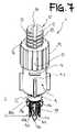
図5Aを参照すると、参照番号30は、実施形態において、本開示のローディングシステム1の一部を形成する送達器具を示す。 Referring to FIG. 5A,
送達器具30は、プロテーゼ2と共に使用されるように構成されているか、または概して、ローディングシステム1によってローディングされることを意図された任意のプロテーゼと共に使用されるように構成されている器具である。
本明細書に示される実施形態では、送達器具は、シャフト31、シャフト31によって支持されるハブ32、およびハブ32に対して第3の軸方向位置IIIから第4の軸方向位置IVまで軸方向にスライド可能である第2のレシーバ33と、を含む。実施形態では、第2のレシーバ33は、ハブ32上でスライド可能なシース部材であり、ハブ32に対して可変の重なりの程度を呈する。 In the embodiment shown herein, the delivery instrument is axially positioned relative to
この目的のために、送達器具30は、実施形態では、軸X1に沿ってレシーバ33に線形軸方向運動を与えるように構成されている回転駆動部材34を含む。他の実施形態では、回転駆動部材34は、線形駆動部材で置き換えられてもよい。 To this end,
ハンドル35は、器具30のより容易な操作を可能にするために、シャフト31の一端に便宜的に提供されてもよい。いくつかの実施形態では、回転駆動部材34(または該当する場合は線形駆動部材)がハンドル35に提供されている。 A
本開示の態様によれば、送達器具30のハブ32は、第1のレシーバ4と結合するように構成されている。この目的のために、結合部材36(例えば、ねじ山つき部材、そうでなければ嵌合ピン)が、レシーバ4と、特に、ハブ28の軸方向延長部29とドッキングし、それに固定するために、ハブ32の自由端に提供され得る。 According to aspects of the present disclosure,
本明細書に示されるものなどの実施形態では、第2のレシーバ33は、第2のレシーバ33に結合された第2の漏斗形状要素37を含み、第2の漏斗形状要素37は、第3の直径D3および第4の直径D4を有し、第4の直径D4は、第3の直径よりも小さく、第3の直径D3よりも第2のレシーバ33に軸方向に近い(図5B)。漏斗形状要素37は、漏斗形状要素4と同様の方法で、レシーバ33に取り外し可能に結合される。例えば、漏斗形状要素37は、ロック機能またはその機構を元に戻すと、分離されるか、または開くことができる2つの半分を含むように提供されてもよく、さもなければ、漏斗形状要素37は、レシーバ33からの取り外しを可能にしながら、レシーバ33と干渉が適合するワンピース要素として提供されてもよい。 In embodiments such as those shown herein, the
図6A~図10、および図1~図5Bからのクロスサポートを参照して、本明細書に開示される実施形態におけるローディングシステム1の動作をここで詳説する。 With reference to FIGS. 6A-10 and cross supports from FIGS. 1-5B, the operation of
図6Aを参照すると、実施形態では、ローディングシステム1は、漏斗形状要素5を含む事前装着キットとして手に入り、グリッパー3は、軸X1に沿った第1の軸方向位置Iにあり、結合要素2Cの係合により、本質的に径方向に拘束されていない状態の心臓弁プロテーゼ2と係合する。結合要素2Cに、弾性フィンガー20、特に弾性フィンガー20の先端21が通され、したがって、フィンガー20とフィンガー20が通過するそれぞれのブレード22との間に各々固定される。 6A, in an embodiment the
心臓弁プロテーゼは、いくつかの実施形態では、例えば、流入部分を環状部分106に有し、シーリングカフSCを、同様にローディングシステム1に事前に装着された漏斗形状要素5に当接させることによって、軸方向にわずかに予荷重をかけるように優先的に装着される(図1および図6Aを参照)。参照されている状態は、心臓弁プロテーゼ2がファントムラインになっている図3Aに見られる状態に対応する。実施形態では、グリッパー3に結合される図4Aおよび図4Bに開示されるプロテーゼ2の部分は、結合要素2Cを含む、(シーリングカフSCで)アーマチュア102の環状部分106に関連付けられた流入部分である。 The heart valve prosthesis is in some embodiments e.g. , are preferentially mounted with a slight axial preload (see FIGS. 1 and 6A). The referenced state corresponds to the state seen in FIG. 3A in which the
いくつかの実施形態では、プロテーゼ2が事前に装着されたローディングシステム1は、無菌保存溶液で満たされ、キャップで閉じられたジャーJ(図1)に格納されて提供されてもよい。 In some embodiments, the
センタリングフランジまたはディスクDSをさらに管状部材6に取り付けて、ジャーJ内で径方向のセンタリングおよび軸方向の支持を提供してもよい。 A centering flange or disc DS may also be attached to the
ローディングシステムがジャーJ(図6A)から取り出されるか、またはいかなる方法でも医師によってつかまれると、心臓弁プロテーゼ2のローディングが開始してもよい。実施形態では、これは、駆動部材12を操作することによって、例えば、図に示されるような回転駆動部材の場合、軸X1の周りで駆動部材を回転させて、第1の軸方向位置Iから第2の軸方向位置IIまでのグリッパー3の軸方向変位を提供することによってなされる。図6Bは、弾性フィンガー20が結合要素2Cと係合している状態で、弁プロテーゼ2をジャーJのすぐ外側に保持する把持部分の詳細を図示する。 Once the loading system is removed from the jar J (Fig. 6A) or grasped in any way by the physician, loading of the
純粋に参照として、以下の説明は、グリッパー3を第1の軸方向位置から第2の軸方向位置まで移動させる駆動作用として時計回りの回転、したがってグリッパー3を第2の軸方向位置から第1の軸方向位置まで移動させる作用として反時計回りの回転が想定されている。明らかに、これは純粋に開示のための想定であり、ローディングシステムは、どのように関連付けがなされていても、動作することができ、つまり、時計回りと反時計回りの方向を入れ替えてもまったく同じように動作する。 Purely by way of reference, the following description refers to clockwise rotation as the driving action to move the
駆動部材12を時計回り方向に回転させると、スタッド10および把持部分14が軸方向に第2の位置IIに向かって並進する一方、レシーバ4は不変でホルダー7に嵌合する。これにより、心臓弁プロテーゼと漏斗形状要素5との間に相対的な軸方向運動が生成され、具体的には、心臓弁プロテーゼ2が軸X1に沿って第1の軸方向位置Iから第2の軸方向位置IIまで軸方向に引きずられ、それによってD1からD2まで異なる直径を通り抜ける。したがって、D1からD2までの異なる直径を通り抜けると、心臓弁プロテーゼ2のアーマチュア102は径方向に収縮する。 Rotation of the
駆動部材12の動作は、図に示される順序で、結合要素2Cが提供されたシーリングカフSCに関連付けられた流入部分である、心臓弁プロテーゼ2のアーマチュアの径方向に折り畳まれた部分が、レシーバ4内にスライドして、それにより、レシーバ4の環状部分26にローディングされるまで続く。 The operation of the
これに関して、フィンガー20とスポーク状形成部27との間の貫通はまた、フィンガー20のグループおよび関連するブレード22とレシーバ4との間の相対運動を可能にし、フィンガー20の径方向の折り畳みにも対応する。実際、第1の軸方向位置Iから第2の軸方向位置IIへの移行中に、フィンガー20は、漏斗形状要素5との相互作用のために、同様に径方向に折り畳まれる。グリッパー3と一体的に移動するガイドブレード22の提供は、説明されるように、フィンガー20の望ましくないねじれまたは回転を防止する。 In this regard, the penetration between the
図3Aに見られるように、実施形態では、直径D2は、レシーバ4の内径、特に環状部分26の内径と同一であるか、または少なくともほとんど一致するように便宜的に提供されてもよいこれは、心臓弁プロテーゼ2の(流入)部分の、漏斗形状要素5からレシーバ4への移行を容易にし、それにより、レシーバ4内への心臓弁プロテーゼ2のよりスムーズなローディングを可能にする。 As seen in FIG. 3A, in embodiments the diameter D2 may conveniently be provided to be the same as, or at least approximately match, the inner diameter of the
第2の軸方向位置IIに到達した結果の状態を図7に示す。具体的には、心臓弁プロテーゼ2の流入部分をレシーバ内にローディングした後、例えば2つの半分5A、5Bを開くことによって、漏斗形状要素5をローディングシステムから取り外す。 The resulting state of reaching the second axial position II is shown in FIG. Specifically, after loading the inflow part of the
上記に関して、グリッパーが第2の軸方向位置IIに到達するときに、弾性フィンガー20がレシーバ4の軸方向外側に位置することに留意することは重要である。これは、レシーバ4に着座し、環状部材26によって取り囲まれて、折り畳み保持されているのは環状部分106(シーリングカフが環状部分106の外側にある)であるという点で、図7にはっきりと見られる。 Regarding the above, it is important to note that the
言い換えれば、レシーバ4のスポーク間領域(すなわち、隣接するスポーク状形成部27間の領域)を通るフィンガー20の変位に続いて、フィンガー20は、(位置IIに向かって)環状部分26を越えて着座することになり、結合要素2Cは依然としてそれによって係合している。プロテーゼ2は、レシーバ4の形状のためにそれ以上移動することができず、すなわち、フィンガー20がレシーバを通過することを可能にするスポーク状形成部27がまさに、プロテーゼ2を軸方向に停止させる。実施形態では、最終位置は、プロテーゼ2の流入部分がレシーバ4内に(およびレシーバ4によって)しっかりと保持されている間、環状部分26から離れて軸方向に突出するわずかに張力をかけられた結合形成部2Cに係合するフィンガー20を特徴とし得る。この状態では、スタッド10が軸方向に引っ込められてグリッパー3を第2の軸方向位置IIに移動させるときに同じフィンガーが実際にその中に収容されることになるため、フィンガー20は実際には管状部材6の内壁によって径方向に折り畳まれた状態で保持される。 In other words, following displacement of
次に、図8、漏斗形状要素37が事前に装着された送達器具30は、レシーバ4に嵌合され、これは、実施形態では、例えば、結合延長部36をレシーバ4の軸方向延長部29と係合することによって、例えば、ねじ接続またはスナップフィット接続によって起こり得る。 Next, FIG. 8, the
漏斗形状要素37の第3の直径D3が、依然としてグリッパー3によって保持されている心臓弁プロテーゼ2と共に提示されるように、嵌合が行われる。 Fitting is performed such that the third diameter D3 of the funnel-shaped
この段階で、レシーバによって拘束されていない心臓弁プロテーゼ2のアーマチュアは、実施形態では、アーチ型支柱108の遠位端が位置している流出部分に対応し、依然として径方向に収縮していない。 At this stage, the armature of the
漏斗形状部材37が弁プロテーゼ2と共に提示されるときに、アーチ型支柱108の遠位端は、第1のレシーバ4による流入部分の収縮のために外側にわずかにフレア状になることもあるが、流出部分はそれ自体実質的に拘束されていない。 When the funnel-shaped
本明細書に示される実施形態では、プロテーゼ2の流出部分のローディングは、送達器具30で行われ、具体的には、プロテーゼ2の流出部分は、第2のレシーバ33にローディングされることが意図されている。In the embodiment shown here, the loading of the outflow portion of the
これを達成するために、実施形態では、第3の軸方向位置IIIから第4の軸方向位置IVまでの第2のレシーバ33の軸方向変位が、駆動部材34を介して、またはレシーバ33の直接軸方向変位によって提供されて、それにより、第2の漏斗形状要素37が、心臓弁プロテーゼ2に対して軸方向に移動する。To achieve this, in an embodiment axial displacement of the
実施形態では、送達器具は、駆動部材34とは独立してレシーバ33の軸方向変位を可能にして、レシーバ33を第3の軸方向位置に向かって高速に前進させるオーバーライド機構を想定してもよい。そのようなオーバーライド機構の例は、例えば、同じ出願人名義の欧州特許第2250975B1号に見出すことができ、これは、参照により本明細書に組み込まれる。上記のオーバーライド機構のおかげで達成されたレシーバ33の前進位置は、実施形態では、(前進した)レシーバ33とハンドル35との間に適合するスペーサークリップCLによって維持されてもよい。 In embodiments, the delivery instrument may also assume an override mechanism that allows axial displacement of the
したがって、プロテーゼ2の流出部分は、D3からD4までの異なる直径を通り抜け、すなわち、それは、第3の直径D3から第4の直径D4まで狭くなる管腔を通り抜ける。したがって、アーチ型支柱108の遠位端の径方向の収縮、およびその過程での流出部分も提供されて、それにより、流出部分が、径方向に収縮した状態で第2のレシーバ33内に適合することになる(図9)。The outflow portion of
次に、漏斗形状要素5と同様に、漏斗形状要素37は、例えば、漏斗形状要素37の2つの半分を開くことによって、送達器具30から取り外されてもよい(図9は、漏斗形状部材37が取り外されたローディングシステム1をすでに示している)。これは、送達器具がレシーバ4に嵌合されているため、この段階で漏斗形状要素37を軸方向に取り除くと、ローディング方法の後続の段階を妨げることになり得るという点で、好ましい解決策と見なされ得る。 Similar to funnel-shaped
したがって、再び図9を参照すると、2つの漏斗形状部材が取り除かれると、第1のものはグリッパーが第2の軸方向位置IIにあるとき、第2のものは第2のレシーバが第4の軸方向位置IVにあるときであることに気づき得、その結果は、送達器具の展開要素を提供する第1のレシーバ4および第2のレシーバ33のものである。より詳細には、実施形態では、第1のレシーバ4は、プロテーゼ2の流入部分(ここでは、本質的に、シーリングカフSCを有するアーマチュアの環状部分106)を径方向に収縮した状態で保持し、後で操作するときにそこで流入部分を解放することが意図された流入展開要素を提供してもよく、第2のレシーバ33は、プロテーゼ2の流出部分(ここでは、本質的に、アーチ型支柱108の遠位端部分120におけるプロテーゼの遠位端)を保持し、後で操作するときにそこで流出部分を開放することが意図された流出展開要素を提供してもよい。 Thus, referring again to FIG. 9, when the two funnel-shaped members are removed, the first is when the gripper is in the second axial position II, the second is when the second receiver is in the fourth position. It can be seen that when in axial position IV, the result is that of the
上記のように送達器具を後で使用するために、レシーバ4は、ハブ32に嵌合されたままで、ホルダー7から取り外される。これをするために、実施形態では、グリッパー3は、最初に心臓弁プロテーゼ2から解放される。 The
これは、実施形態では、駆動部材12を反時計回りに、またはより一般的には、グリッパーを第2の軸方向位置IIに変位させる方向と反対の方向に動作させることによって達成される。駆動部材12のこの動作は、弾性フィンガー20で把持部分14を位置Iに向かって軸方向に、最終的には管状部材6から離れるように前進させる。フィンガー20が管状部材6から徐々に出る間、管状部材によってそれに加えられた径方向の収縮作用も同様に解放され(これはまた、弾性フィンガー20のフレアパターンのおかげで)、したがって、フィンガー20が、ローディング操作の開始時に呈する径方向に分岐された状態に戻り、さらにそれを超えて前述の拘束されていない状態に対応するより分岐した配置に至ることを可能にする。すなわち、弾性フィンガーは、拘束されていない状態に戻って拡張することができ、ブレード22との係合を、少なくともブレード22の開口部22Wで解放して、それにより、プロテーゼ2が、把持部分14からスムーズに解放されることを可能にする。 This is achieved in the embodiment by operating the
同じ解放は、心臓弁プロテーゼ2の流入部分が、レシーバ4の環状部分26によって径方向に収縮されたままであるため、心臓弁プロテーゼ2の流入部分には拡張されない。 The same release is not extended to the inflow portion of the
グリッパー3は、フィンガー20を介してプロテーゼ2を径方向外向きに拘束するため、後者は、フィンガー20がプロテーゼ2に対して径方向外向きの運動を受けたときに、結合要素2Cと係合してそれらを保持する停止、または別様の拘束特徴を有さない。 The
したがって、プロテーゼ2がレシーバ4内に残るが、フィンガー20は、フィンガー20が単に径方向外向き方向において結合要素2Cとの係合から外れることを可能にする分岐した状態に向かって/に戻るように付勢され(図9の回転θ20を参照)、それにより、プロテーゼ2の流入部分をグリッパー3から解放する。 Thus, the
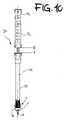
次に、レシーバ4は、ハブ32に安定して取り付けられたままで、ホルダー7から安全に切り離されてもよい(図10)。したがって、ローディングシステム1によって実行されるローディング方法の終わりに、実施形態では、結果は、2つの展開要素を特徴とする送達器具30のものであり、一方はレシーバ33によって提供され、他方は、以前は別のデバイスの部分であるレシーバ4によって提供され、両方の展開要素は、器具30によって制御され得る。プロテーゼ2の流入部分は、レシーバ4によって径方向に折り畳まれて保持される一方、流出部分は、レシーバ33によって径方向に折り畳まれて保持される。代わりに、流入部分と流出部分との間のアーマチュアの部分は、参照により本明細書に組み込まれる、本件出願人名義の欧州特許第EP2238947B1号の主題と同様の方法で、展開要素による径方向の収縮がないままにされる。 The
要約すると、実施形態では、方法は、同様に送達器具30を含むローディングシステム1によって、人工心臓弁を送達器具にローディングすることと定義され、その方法は、
グリッパー3を第1の軸方向位置Iから第2の軸方向位置IIに変位させて、心臓弁プロテーゼ2の少なくとも1つの部分(例えば、流入部分)を径方向に折り畳まれた状態で、第1のレシーバ4内に適合させることと、
第1の漏斗形状要素5をローディングシステム1から分離することと、
第1のレシーバ4を送達器具30のハブ32に結合することと、
第2のレシーバ33を第3の軸方向位置IIIから第4の軸方向位置IVに変位させて、心臓弁プロテーゼ2の第2の部分(例えば、流出部分)を径方向に折り畳まれた状態で第2のレシーバ33内に適合させることと、
第2の漏斗形状要素37を送達器具から分離することと、
第1のレシーバ4が送達器具30のハブ32に取り付けられた状態を維持しながら、第1のレシーバ4をホルダー7から分離することと、を含む。In summary, in an embodiment, a method is defined as loading a prosthetic heart valve onto a delivery device by a
With the
separating the first funnel-shaped
coupling the
displacing the
separating the second funnel-shaped
separating the
本開示のアイデアおよび原理は同じままで、構成の詳細および実施形態は、本開示の範囲から逸脱することなく、純粋に例として説明および図示されたものに関して大きく異なってもよい。 While the ideas and principles of the present disclosure remain the same, constructional details and embodiments may vary greatly with respect to what has been described and illustrated purely by way of example without departing from the scope of the present disclosure.
例えば、実施形態では、レシーバ4は、移植されるプロテーゼの軸方向の延長部全体を覆うようにサイズ設定および寸法決定されてもよく、それにより、第2のレシーバ33は必要とされなくてもよい。したがって、これらの実施形態では、ローディングシステム1は、プロテーゼ2が取り付けられたグリッパー3、関連する作動設備(すなわち、例えば、駆動部材12を備えた管状部材6)、上記のように寸法決定された第1のレシーバ、および第1の漏斗形状要素5のみを含んでもよい。いくつかの実施形態では、第1の軸方向位置Iから第2の軸方向位置IIまでのグリッパー3の変位は、プロテーゼ全体のレシーバ4へのローディングをもたらす。プロテーゼからのグリッパー3の取り外しは、すぐ上に開示したように起こり得るが、送達器具がローディング作用を完了する必要がなくなると、全長レシーバ4を後で送達器具に結合することができる。 For example, in embodiments the
いくつかの実施形態では、レシーバ4には、プロテーゼ2の軸方向の長さを覆うことが意図されてもよく、かつハブ28に対して軸方向にスライド可能であり得る送達シースとして長さが延長された環状部分が提供されてもよい。したがって、ハブ28および環状部分26は、送達器具との2つの別個の結合インターフェースを有し得、一方は、送達器具のシャフトの静的部分と嵌合することが意図された、ハブのためのものであり、他方は、その軸方向変位のために送達器具の作動部材と嵌合することが意図された、シース26のためのものである。 In some embodiments,
追加的に、本明細書に開示される実施形態では、プロテーゼ2の流入部分は、グリッパーに事前に装着され、後でレシーバ4内に着座していると言及される一方、プロテーゼ2の流出部分は、第2のレシーバ33に着座している結合と言及され、他の実施形態では、それらは、逆に配置されてもよく、すなわち、流入部分がレシーバ33内に着座し、流出部分がグリッパーに事前に装着され、後でレシーバ4内に着座する。これに関して、アーチ型支柱108の遠位部分120がヘアピン形状で提供されるときに、遠位部分120は、グリッパー3、具体的には、弾性フィンガー20のために自然な係合部位を提供してもよい。 Additionally, in the embodiments disclosed herein, the inflow portion of the
いずれにせよ、後で送達器具の一部として使用されるレシーバ要素へのプロテーゼのローディングは、スムーズかつ効率的に、そして何よりも、プロテーゼ2が格納されているジャーから出てくる準備ができているデバイスを使用して実行することができ、それにより、ジャーから送達器具までの心臓弁プロテーゼの操作が大幅に簡素化される。 In any event, the loading of the prosthesis into the receiver element, which is later used as part of the delivery device, is smooth and efficient, and above all, ready to emerge from the jar in which the
本開示のアイデアおよび原理は同じままで、構成の詳細および実施形態は、本開示の範囲から逸脱することなく、純粋に例として説明および図示されたものに関して大きく異なってもよい。 While the ideas and principles of the present disclosure remain the same, constructional details and embodiments may vary greatly with respect to what has been described and illustrated purely by way of example without departing from the scope of the present disclosure.
本開示の範囲から逸脱することなく、議論された例示的な実施形態に様々な修正および追加を行うことができる。例えば、上記の実施形態は特定の特徴に言及しているが、本開示の範囲は、特徴の異なる組み合わせを有する実施形態、および記載された特徴のすべてを含まない実施形態も含む。したがって、本開示の範囲は、そのすべての均等物とともに、特許請求の範囲に含まれるそのようなすべての代替、修正、および変形を包含することが意図されている。
〔態様1〕
径方向に収縮可能なアーマチュア(102)と、前記アーマチュア(102)に結合された人工心臓弁(104)と、を含む心臓弁プロテーゼ(2)のためのローディングシステム(1)であって、前記アーマチュア(102)は、少なくとも1つの径方向に収縮可能な環状部分(106)を有し、前記ローディングシステム(1)は、
前記ローディングシステム(1)の長手方向軸(X1)に沿って、第1の軸方向位置(I)から第2の軸方向位置(II)まで軸方向に動作可能なグリッパー(3)であって、前記第1の軸方向位置(I)において、前記グリッパー(3)は、前記アーマチュア(102)が径方向に拡張した状態で、前記心臓弁プロテーゼ(2)と係合する、グリッパー(3)と、
前記心臓弁プロテーゼ(2)のための第1のレシーバ(4)であって、前記第1のレシーバ(4)が、前記心臓弁プロテーゼ(2)による前記第1のレシーバ(4)の係合時に、前記心臓弁プロテーゼ(2)の少なくとも第1の部分(106)を径方向に収縮した状態で保持するように構成されており、前記グリッパー(3)が、前記第1のレシーバ(4)に対して軸方向に変位可能である、第1のレシーバ(4)と、
前記第1のレシーバ(4)を取り囲む第1の漏斗形状要素(5)であって、前記第1の漏斗形状要素(5)が、第1の直径(D1)および第2の直径(D2)を有し、前記第2の直径(D2)が、前記第1の直径(D1)よりも小さく、前記第1の直径(D1)よりも前記第1のレシーバ(4)に軸方向に近く配置され、前記グリッパー(3)は、前記第1の漏斗形状要素(5)に対して軸方向に変位可能である、第1の漏斗形状要素(5)と、を含み、
前記第1の軸方向位置(I)から前記第2の軸方向位置(II)への移行において、前記グリッパー(3)が、前記心臓弁プロテーゼ(2)を前記第1の直径(D1)から前記第2の直径(D2)まで前記第1の漏斗形状要素(5)を通って軸方向に変位させ、それにより、前記心臓弁プロテーゼ(2)の前記アーマチュア(102)の径方向の収縮、および前記第2の軸方向位置(II)への到達時に、径方向に収縮した状態での、前記第1のレシーバ(4)内への前記少なくとも第1の部分(106)の適合を提供するように構成されている、ローディングシステム(1)。
〔態様2〕
前記グリッパー(3)に対して軸方向に固定されている管状部材(6)をさらに含み、前記管状部材(6)は、前記第1のレシーバ(4)が嵌合するホルダー(7)を含む、態様1に記載のローディングシステム(1)。
〔態様3〕
前記グリッパー(3)は、前記管状部材(6)によって包まれたスタッド(10)と、前記スタッド(10)の一端にある把持部分(14)と、を含み、前記管状部材(6)は、前記スタッド(10)と係合する駆動部材(12)をさらに含み、前記駆動部材(12)は、前記駆動部材(12)が動作すると、前記スタッド(10)の軸方向変位を提供し、前記把持部分(14、20)は、前記第1の軸方向位置(I)において、前記心臓弁プロテーゼの前記少なくとも第1の部分の結合要素(2C)と係合する、態様2に記載のローディングシステム(1)。
〔態様4〕
前記スタッド(10)には、ねじ山(16)がついており、前記駆動部材(12)が、前記スタッド(10)の前記ねじ山(16)に係合するねじ山つき回転駆動部材(12)である、態様3に記載のローディングシステム(1)。
〔態様5〕
前記スタッドが、中空スタッド(10)であり、軸方向スロット(17)を含み、前記ホルダー(7)が、前記管状部材(6)内を、前記長手方向軸(X1)に沿って軸方向に、かつ前記長手方向軸(X1)と同軸に延在し、前記中空スタッド(10)が、前記ホルダー(7)の周りにスライド可能に適合し、前記軸方向スロット(17)が前記ホルダー(7)を前記管状部材(6)に接続する架橋部材(8、9)を収容している、態様2または3に記載のローディングシステム(1)。
〔態様6〕
前記グリッパー(3)が、複数の弾性フィンガー部材(20)を含む把持部分(14)を含み、前記弾性フィンガー部材(20)が、前記心臓弁プロテーゼ(2)の径方向外向きに前記心臓弁プロテーゼ(2)と係合し、前記グリッパー(3)が前記第1の漏斗形状要素(5)に対して前記第1の軸方向位置(I)から前記第2の軸方向位置(II)まで軸方向に変位すると、径方向分岐状態から径方向折り畳み状態に径方向に変位可能であり、それにより、前記心臓弁プロテーゼ(2)の前記アーマチュア(102)の径方向の収縮を提供する、態様1~5のいずれかに記載のローディングシステム(1)。
〔態様7〕
各弾性フィンガー(20)がガイドブレード(22)に関連付けられ、各ガイドブレード(22)は、前記弾性フィンガー(20)が前記径方向分岐状態から前記径方向折り畳み状態まで変位している間、前記弾性フィンガー(20)を収容するように構成された長手方向貫通スロット(24)を含み、それにより、前記弾性フィンガー(20)を長手方向(X1)に沿って整列させたままにする、態様6に記載のローディングシステム(1)。
〔態様8〕
前記第1の漏斗形状要素(5)が、前記第1のレシーバ(4)に取り外し可能に結合されている、態様1~7のいずれかに記載のローディングシステム(1)。
〔態様9〕
前記心臓弁プロテーゼ(2)のための送達器具(30)をさらに含み、前記送達器具(30)が、シャフト(31)と、前記シャフト(31)によって支持されるハブ(32)と、前記ハブ(32)に対して第3の軸方向位置(III)から第4の軸方向位置(IV)まで軸方向にスライド可能である第2のレシーバ(33)と、を含み、
前記送達器具(30)の前記ハブ(32)は、前記第1のレシーバ(4)と結合するように構成されており、
前記第2のレシーバ(33)は、それに結合された第2の漏斗形状要素(5)を含み、前記第2の漏斗形状要素(5)が、第3の直径(D3)および第4の直径(D4)を有し、前記第4の直径(D4)が、前記第3の直径(D3)よりも小さく、前記第3の直径(D3)よりも前記第2のレシーバ(33)に軸方向に近く、前記第3の直径(D3)が、前記グリッパー(3)に結合された前記心臓弁プロテーゼ(2)とともに提示され、
さらに、前記第3の軸方向位置(III)から前記第4の軸方向位置(IV)までの前記第2のレシーバ(33)の軸方向変位において、前記第2の漏斗形状要素(5)が、前記心臓弁プロテーゼ(2)に対して移動し、それにより、前記アーマチュア(102)の第2の部分が、前記第3の直径(D3)から前記第4の直径(D4)まで狭まる管腔を通り抜け、径方向に収縮した状態で前記第2のレシーバ(33)内に適合する、態様1~8のいずれかに記載のローディングシステム(1)。
〔態様10〕
前記第2の漏斗形状要素(37)が、前記第2のレシーバ(33)に取り外し可能に結合されている、態様9に記載のローディングシステム(1)。
〔態様11〕
前記第1のレシーバ(4)が、前記ホルダー(7)に取り外し可能に結合されている、態様2または10に記載のローディングシステム(1)。
〔態様12〕
前記レシーバ、前記グリッパー、および前記グリッパーに取り付けられた前記心臓弁プロテーゼが、保存溶液で満たされたジャー(J)に格納され、前記第1の漏斗形状要素(5)が、前記第1のレシーバ(4)に事前に装着されている、態様1に記載のローディングシステム。
〔態様13〕
前記ローディングシステムは、径方向に収縮可能なアーマチュア(102)と、前記アーマチュア(102)によって支持される人工心臓弁(104)と、を含む心臓弁プロテーゼ(2)をさらに含み、前記アーマチュア(102)が、少なくとも1つの径方向に収縮可能な環状部分(106)を有し、前記第1の軸方向位置(I)において、前記グリッパー(3)は、前記アーマチュア(102)が径方向に拡張した状態で、前記心臓弁プロテーゼ(2)と係合する、態様1または12に記載のローディングシステム。
〔態様14〕
態様9に記載のローディングシステムを使用して、人工心臓弁を送達器具上にローディングする方法であって、
前記グリッパー(3)を前記第1の軸方向位置(I)から前記第2の軸方向位置(II)に変位させて、前記心臓弁プロテーゼ(2)の少なくとも1つの部分(106、SC)を径方向に折り畳まれた状態で、前記第1のレシーバ(4)内に適合させることと、
前記第1の漏斗形状要素(5)を前記ローディングシステム(1)から分離することと、
前記第1のレシーバ(4)を前記送達器具(30)の前記ハブ(32)に結合することと、
前記第2のレシーバ(33)を前記第3の軸方向位置(III)から前記第4の軸方向位置(IV)に変位させて、前記心臓弁プロテーゼ(2)の前記第2の部分(120)を径方向に折り畳まれた状態で、前記第2のレシーバ(33)内に適合させることと、
前記第2の漏斗形状要素(37)を前記送達器具(30)から分離することと、
前記第1のレシーバ(4)が前記送達器具(30)の前記ハブ(32)に取り付けられた状態を維持しながら、前記第1のレシーバ(4)を前記ホルダー(7)から分離することと、を含む、方法。
〔態様15〕
前記第1のレシーバ(4)を前記ホルダー(7)から分離することは、前記プロテーゼ(2)の少なくとも一部分が前記第1のレシーバにローディングされた状態で、前記グリッパー(3)を前記第1の軸方向位置に向けて戻すように軸方向に変位させて、前記プロテーゼ(2)から前記グリッパーを解放することを含む、態様14に記載の方法。
〔態様16〕
前記第2の軸方向位置(II)において、前記弾性フィンガー(20)が、前記第1のレシーバ(4)の軸方向外側に位置しており、前記管状部材(6)によって径方向に収縮した状態に保持され、前記グリッパー(3)を前記第1の軸方向位置に向けて戻すように軸方向に変位させることは、前記管状部材(6)の径方向の収縮作用から前記弾性フィンガー(20)を解放し、それにより、前記弾性フィンガー(20)を、前記結合要素(2C)に対する前記弾性フィンガーの径方向外向きの運動によって、前記心臓弁プロテーゼ(2)の前記少なくとも第1の部分の結合要素(2C)から解放する、態様15に記載のローディングシステム。
〔態様17〕
態様1~13のいずれかに記載のローディングシステムを使用して、人工心臓弁を送達器具にローディングする方法であって、
前記グリッパー(3)を前記第1の軸方向位置(I)から前記第2の軸方向位置(II)まで変位させて、径方向に折り畳まれた状態で、前記心臓弁プロテーゼ(2)を前記第1のレシーバ(4)内に適合させることと、
前記第1の漏斗形状要素(5)を前記ローディングシステム(1)から分離することと、
前記第1のレシーバ(4)を取り外し、前記第1のレシーバ(4)を送達器具に結合することと、を含む、方法。
〔態様18〕
前記第1のレシーバは、送達シースとして長さが延長され、かつハブ(28)に対して軸方向にスライド可能である環状部分を含み、長さが延長された前記環状部分が、前記プロテーゼの軸方向延長部を覆うように構成されている、態様17に記載の方法。
〔態様19〕
前記環状部分が、前記送達器具の軸方向変位のために前記送達器具の作動部材と嵌合することが意図されており、前記ハブが、前記送達器具のシャフトの静的部分と嵌合することが意図されている、態様18に記載の方法。Various modifications and additions may be made to the exemplary embodiments discussed without departing from the scope of this disclosure. For example, although the above embodiments refer to particular features, the scope of the disclosure also includes embodiments with different combinations of features and embodiments that do not include all of the described features. Accordingly, the scope of the present disclosure is intended to embrace all such alternatives, modifications and variations that fall within the scope of the claims along with all equivalents thereof.
[Aspect 1]
A loading system (1) for a heart valve prosthesis (2) comprising a radially contractible armature (102) and a prosthetic heart valve (104) coupled to said armature (102), said The armature (102) has at least one radially contractible annular portion (106), said loading system (1) comprising:
a gripper (3) axially movable from a first axial position (I) to a second axial position (II) along the longitudinal axis (X1) of said loading system (1); , in said first axial position (I), said gripper (3) engages said heart valve prosthesis (2) with said armature (102) radially expanded. When,
A first receiver (4) for said heart valve prosthesis (2), said first receiver (4) engaging said heart valve prosthesis (2) with said first receiver (4). Sometimes configured to hold at least a first portion (106) of the heart valve prosthesis (2) in a radially contracted state, the gripper (3) is configured to hold the first receiver (4). a first receiver (4) axially displaceable with respect to
A first funnel-shaped element (5) surrounding said first receiver (4), said first funnel-shaped element (5) having a first diameter (D1) and a second diameter (D2) wherein said second diameter (D2) is smaller than said first diameter (D1) and is axially closer to said first receiver (4) than said first diameter (D1). and said gripper (3) comprises a first funnel-shaped element (5) axially displaceable with respect to said first funnel-shaped element (5);
In transition from said first axial position (I) to said second axial position (II), said gripper (3) moves said heart valve prosthesis (2) from said first diameter (D1). axial displacement through said first funnel-shaped element (5) to said second diameter (D2), thereby radially contracting said armature (102) of said heart valve prosthesis (2); and upon reaching said second axial position (II), providing a fit of said at least first portion (106) within said first receiver (4) in a radially contracted state. A loading system (1) configured to:
[Aspect 2]
Further comprising a tubular member (6) axially fixed to said gripper (3), said tubular member (6) comprising a holder (7) in which said first receiver (4) is fitted. A loading system (1) according to
[Aspect 3]
Said gripper (3) comprises a stud (10) encased by said tubular member (6) and a gripping portion (14) at one end of said stud (10), said tubular member (6) comprising: further comprising a drive member (12) engaging said stud (10), said drive member (12) providing axial displacement of said stud (10) upon operation of said drive member (12); A loading system according to
[Aspect 4]
Said stud (10) is threaded (16) and said drive member (12) is a threaded rotary drive member (12) engaging said thread (16) of said stud (10). A loading system (1) according to
[Aspect 5]
Said stud is a hollow stud (10) and includes an axial slot (17), said holder (7) axially moving within said tubular member (6) along said longitudinal axis (X1). and extending coaxially with said longitudinal axis (X1), said hollow stud (10) being slidably fitted around said holder (7), said axial slot (17) extending into said holder (7). ) to said tubular member (6).
[Aspect 6]
Said gripper (3) comprises a gripping portion (14) comprising a plurality of resilient finger members (20), said resilient finger members (20) extending radially outwardly of said heart valve prosthesis (2) to said heart valve. Engaging with the prosthesis (2), the gripper (3) moves relative to the first funnel-shaped element (5) from the first axial position (I) to the second axial position (II). wherein axial displacement is radially displaceable from a radially diverging state to a radially collapsed state, thereby providing radial contraction of said armature (102) of said heart valve prosthesis (2). 6. A loading system (1) according to any one of 1 to 5.
[Aspect 7]
Each resilient finger (20) is associated with a guide blade (22), each guide blade (22) being adapted to the said
[Aspect 8]
A loading system (1) according to any preceding aspect, wherein said first funnel-shaped element (5) is removably coupled to said first receiver (4).
[Aspect 9]
further comprising a delivery instrument (30) for said heart valve prosthesis (2), said delivery instrument (30) comprising a shaft (31), a hub (32) supported by said shaft (31), and said hub a second receiver (33) axially slidable relative to (32) from a third axial position (III) to a fourth axial position (IV);
said hub (32) of said delivery device (30) is configured to mate with said first receiver (4);
Said second receiver (33) includes a second funnel-shaped element (5) coupled thereto, said second funnel-shaped element (5) having a third diameter (D3) and a fourth diameter (D4), wherein said fourth diameter (D4) is less than said third diameter (D3) and axially towards said second receiver (33) than said third diameter (D3) near said third diameter (D3) is presented with said heart valve prosthesis (2) coupled to said gripper (3);
Furthermore, upon axial displacement of said second receiver (33) from said third axial position (III) to said fourth axial position (IV), said second funnel-shaped element (5) is , moves relative to said heart valve prosthesis (2) such that the second portion of said armature (102) narrows from said third diameter (D3) to said fourth diameter (D4). and fits within said second receiver (33) in a radially contracted state.
[Aspect 10]
A loading system (1) according to aspect 9, wherein said second funnel-shaped element (37) is removably coupled to said second receiver (33).
[Aspect 11]
A loading system (1) according to
[Aspect 12]
Said receiver, said gripper and said heart valve prosthesis attached to said gripper are stored in a jar (J) filled with a storage solution, said first funnel-shaped element (5) A loading system according to
[Aspect 13]
Said loading system further comprises a heart valve prosthesis (2) comprising a radially contractible armature (102) and a prosthetic heart valve (104) supported by said armature (102), said armature (102) ) has at least one radially contractible annular portion (106), and in said first axial position (I), said gripper (3) is configured such that said armature (102) is radially expanded 13. A loading system according to
[Aspect 14]
A method of loading a prosthetic heart valve onto a delivery device using the loading system of aspect 9, comprising:
displacing said gripper (3) from said first axial position (I) to said second axial position (II) to grip at least one portion (106, SC) of said heart valve prosthesis (2); Fitting in said first receiver (4) in a radially folded state;
separating said first funnel-shaped element (5) from said loading system (1);
coupling said first receiver (4) to said hub (32) of said delivery device (30);
displacing said second receiver (33) from said third axial position (III) to said fourth axial position (IV) to displace said second portion (120) of said heart valve prosthesis (2); ) in a radially folded state into said second receiver (33);
separating said second funnel-shaped element (37) from said delivery device (30);
separating the first receiver (4) from the holder (7) while maintaining the first receiver (4) attached to the hub (32) of the delivery device (30); , including, methods.
[Aspect 15]
Separating said first receiver (4) from said holder (7) moves said gripper (3) to said first receiver with at least a portion of said prosthesis (2) loaded into said first receiver. 15. A method according to
[Aspect 16]
In said second axial position (II) said resilient fingers (20) are located axially outside said first receiver (4) and are radially contracted by said tubular member (6). Axial displacement of said gripper (3) back towards said first axial position, held in place, causes said resilient finger (20) to move away from the action of radial contraction of said tubular member (6). ) thereby releasing said resilient fingers (20) from said at least first portion of said heart valve prosthesis (2) by radially outward movement of said resilient fingers relative to said coupling element (2C). 16. A loading system according to
[Aspect 17]
A method of loading a prosthetic heart valve onto a delivery device using the loading system of any of aspects 1-13, comprising:
Said gripper (3) is displaced from said first axial position (I) to said second axial position (II) to hold said heart valve prosthesis (2) in said radially collapsed state. fitting within a first receiver (4);
separating said first funnel-shaped element (5) from said loading system (1);
detaching said first receiver (4) and coupling said first receiver (4) to a delivery device.
[Aspect 18]
The first receiver includes an annular portion elongated in length as a delivery sheath and axially slidable relative to a hub (28), wherein the elongated annular portion extends from the prosthesis. 18. The method of
[Aspect 19]
The annular portion is intended to mate with an actuating member of the delivery device for axial displacement of the delivery device, and the hub mates with a static portion of the shaft of the delivery device. 19. The method of
Claims (16)
Translated fromJapanese前記ローディングシステム(1)の長手方向軸(X1)に沿って、第1の軸方向位置(I)から第2の軸方向位置(II)まで軸方向に動作可能なグリッパー(3)であって、前記第1の軸方向位置(I)において、前記グリッパー(3)は、前記アーマチュア(102)が径方向に拡張した状態で、前記心臓弁プロテーゼ(2)と係合する、グリッパー(3)と、
前記心臓弁プロテーゼ(2)のための第1のレシーバ(4)であって、前記第1のレシーバ(4)が、前記心臓弁プロテーゼ(2)による前記第1のレシーバ(4)の係合時に、前記心臓弁プロテーゼ(2)の少なくとも環状部分(106)を径方向に収縮した状態で保持するように構成されており、前記グリッパー(3)が、前記第1のレシーバ(4)に対して軸方向に変位可能である、第1のレシーバ(4)と、
前記第1のレシーバ(4)を取り囲む第1の漏斗形状要素(5)であって、前記第1の漏斗形状要素(5)が、第1の直径部分(D1)および第2の直径部分(D2)を有し、前記第2の直径部分(D2)が、前記第1の直径部分(D1)よりも小さく、前記第1の直径部分(D1)よりも前記第1のレシーバ(4)に軸方向に近く配置され、前記グリッパー(3)は、前記第1の漏斗形状要素(5)に対して軸方向に変位可能である、第1の漏斗形状要素(5)と、を含み、
前記第1の軸方向位置(I)から前記第2の軸方向位置(II)への移行において、前記グリッパー(3)が、前記心臓弁プロテーゼ(2)を前記第1の直径部分(D1)から前記第2の直径部分(D2)まで前記第1の漏斗形状要素(5)を通って軸方向に変位させ、それにより、前記心臓弁プロテーゼ(2)の前記アーマチュア(102)の径方向の収縮、および前記第2の軸方向位置(II)への到達時に、径方向に収縮した状態での、前記第1のレシーバ(4)内への前記少なくとも環状部分(106)の適合を提供するように構成されており、
前記ローディングシステム(1)は、前記グリッパー(3)に対して軸方向に固定されている管状部材(6)をさらに含み、前記管状部材(6)は、前記第1のレシーバ(4)が嵌合するホルダー(7)を含み、
前記グリッパー(3)は、前記管状部材(6)によって包まれたスタッド(10)と、前記スタッド(10)の一端にある把持部分(14)と、を含み、前記管状部材(6)は、前記スタッド(10)と係合する駆動部材(12)をさらに含み、前記駆動部材(12)は、前記駆動部材(12)が動作すると、前記スタッド(10)の軸方向変位を提供し、前記把持部分(14、20)は、前記第1の軸方向位置(I)において、前記心臓弁プロテーゼの前記少なくとも第1の部分の結合要素(2C)と係合し、
前記スタッド(10)には、ねじ山(16)がついており、前記駆動部材(12)が、前記スタッド(10)の前記ねじ山(16)に係合するねじ山つき回転駆動部材(12)である、ローディングシステム(1)。A loading system (1) for a heart valve prosthesis (2) comprising a radially contractible armature (102) and a prosthetic heart valve (104) coupled to said armature (102), said The armature (102) has at least one radially contractible annular portion (106), said loading system (1) comprising:
a gripper (3) axially movable from a first axial position (I) to a second axial position (II) along the longitudinal axis (X1) of said loading system (1); , in said first axial position (I), said gripper (3) engages said heart valve prosthesis (2) with said armature (102) radially expanded. When,
A first receiver (4) for said heart valve prosthesis (2), said first receiver (4) engaging said heart valve prosthesis (2) with said first receiver (4). Sometimes configured to hold at least an annular portion (106) of the heart valve prosthesis (2) in a radially contracted state, the gripper (3) is positioned against the first receiver (4). a first receiver (4) axially displaceable by
A first funnel-shaped element (5) surrounding said first receiver (4), said first funnel-shaped element (5) comprising a first diameter portion (D1) and a second diameter portion ( D2), said second diameter portion (D2) being smaller than said first diameter portion (D1) and closer to said first receiver (4) than said first diameter portion (D1). a first funnel-shaped element (5) arranged axially close, said gripper (3) being axially displaceable relative to said first funnel-shaped element (5);
In transition from said first axial position (I) to said second axial position (II), said gripper (3) grips said heart valve prosthesis (2) through said first diameter portion (D1). to said second diameter portion (D2) through said first funnel-shaped element (5), thereby radially displacing said armature (102) of said heart valve prosthesis (2) from contracting and, upon reaching said second axial position (II), providing a fit of said at least annular portion (106) within said first receiver (4) in a radially contracted state; is configuredas
Said loading system (1) further comprises a tubular member (6) axially fixed to said gripper (3), said tubular member (6) being fitted with said first receiver (4). including a mating holder (7);
Said gripper (3) comprises a stud (10) encased by said tubular member (6) and a gripping portion (14) at one end of said stud (10), said tubular member (6) comprising: further comprising a drive member (12) engaging said stud (10), said drive member (12) providing axial displacement of said stud (10) upon operation of said drive member (12); gripping portions (14, 20) engage coupling elements (2C) of said at least first portion of said heart valve prosthesis in said first axial position (I);
Said stud (10) is threaded (16) and said drive member (12) is a threaded rotary drive member (12) engaging said thread (16) of said stud (10). A loading system (1).
前記送達器具(30)の前記ハブ(32)は、前記第1のレシーバ(4)と結合するように構成されており、
前記第2のレシーバ(33)は、それに結合された第2の漏斗形状要素(5)を含み、前記第2の漏斗形状要素(5)が、第3の直径部分(D3)および第4の直径部分(D4)を有し、前記第4の直径部分(D4)が、前記第3の直径部分(D3)よりも小さく、前記第3の直径部分(D3)よりも前記第2のレシーバ(33)に軸方向に近く、前記第3の直径部分(D3)が、前記グリッパー(3)に結合された前記心臓弁プロテーゼ(2)とともに提示され、
さらに、前記第3の軸方向位置(III)から前記第4の軸方向位置(IV)までの前記第2のレシーバ(33)の軸方向変位において、前記第2の漏斗形状要素(5)が、前記心臓弁プロテーゼ(2)に対して移動し、それにより、前記心臓弁プロテーゼ(2)の流出部分が、前記第3の直径部分(D3)から前記第4の直径部分(D4)まで狭まる管腔を通り抜け、径方向に収縮した状態で前記第2のレシーバ(33)内に適合する、請求項1~5のいずれか1項に記載のローディングシステム(1)。further comprising a delivery instrument (30) for said heart valve prosthesis (2), said delivery instrument (30) comprising a shaft (31), a hub (32) supported by said shaft (31), and said hub a second receiver (33) axially slidable relative to (32) from a third axial position (III) to a fourth axial position (IV);
said hub (32) of said delivery device (30) is configured to mate with said first receiver (4);
Said second receiver (33) includes a second funnel-shaped element (5) coupled thereto, said second funnel-shaped element (5) having a third diameter portion (D3) and a fourth diameter portion (D3). a diameter portion (D4), wherein said fourth diameter portion (D4) is smaller than said third diameter portion (D3) and is closer to said second receiver than said third diameter portion (D3); 33), said third diameter portion (D3) being presented with said heart valve prosthesis (2) coupled to said gripper (3);
Furthermore, upon axial displacement of said second receiver (33) from said third axial position (III) to said fourth axial position (IV), said second funnel-shaped element (5) is , relative to said heart valve prosthesis (2), whereby the outflow portion of said heart valve prosthesis (2) narrows from said third diameter portion (D3) to said fourth diameter portion (D4). A loading system (1 ) according to any one of the preceding claims, passing through a lumen and fitting in said second receiver (33) in a radially contracted state.
前記グリッパー(3)を前記第1の軸方向位置(I)から前記第2の軸方向位置(II)に変位させて、前記心臓弁プロテーゼ(2)の少なくとも1つの環状部分(106)を径方向に折り畳まれた状態で、前記第1のレシーバ(4)内に適合させることと、
前記第1の漏斗形状要素(5)を前記ローディングシステム(1)から分離することと、
前記第1のレシーバ(4)を前記送達器具(30)の前記ハブ(32)に結合することと、
前記第2のレシーバ(33)を前記第3の軸方向位置(III)から前記第4の軸方向位置(IV)に変位させて、前記心臓弁プロテーゼ(2)の前記流出部分(120)を径方向に折り畳まれた状態で、前記第2のレシーバ(33)内に適合させることと、
前記第2の漏斗形状要素(37)を前記送達器具(30)から分離することと、
前記第1のレシーバ(4)が前記送達器具(30)の前記ハブ(32)に取り付けられた状態を維持しながら、前記第1のレシーバ(4)を前記ホルダー(7)から分離することと、を含む、方法。A method of loading a prosthetic heart valve onto a delivery device using the loading system of claim6 , comprising:
Said gripper (3) is displaced from said first axial position (I) to said second axial position (II) to radially displace at least one annular portion (106) of said heart valve prosthesis (2). directionally folded to fit within said first receiver (4);
separating said first funnel-shaped element (5) from said loading system (1);
coupling said first receiver (4) to said hub (32) of said delivery device (30);
displacing said second receiver (33) from said third axial position (III) to said fourth axial position (IV) to displace said outflow portion (120) of said heart valve prosthesis (2); fitting within said second receiver (33) in a radially folded state;
separating said second funnel-shaped element (37) from said delivery device (30);
separating the first receiver (4) from the holder (7) while maintaining the first receiver (4) attached to the hub (32) of the delivery device (30); , including, methods.
前記グリッパー(3)を前記第1の軸方向位置(I)から前記第2の軸方向位置(II)まで変位させて、径方向に折り畳まれた状態で、前記心臓弁プロテーゼ(2)を前記第1のレシーバ(4)内に適合させることと、
前記第1の漏斗形状要素(5)を前記ローディングシステム(1)から分離することと、
前記第1のレシーバ(4)を取り外し、前記第1のレシーバ(4)を送達器具に結合することと、を含む、方法。A method of loading a prosthetic heart valve onto a delivery device using the loading system of any one of claims1-10 , comprising:
Displacement of said gripper (3) from said first axial position (I) to said second axial position (II) to hold said heart valve prosthesis (2) in said radially collapsed state. fitting within a first receiver (4);
separating said first funnel-shaped element (5) from said loading system (1);
detaching said first receiver (4) and coupling said first receiver (4) to a delivery device.
Applications Claiming Priority (1)
| Application Number | Priority Date | Filing Date | Title |
|---|---|---|---|
| PCT/IB2018/053648WO2019224582A1 (en) | 2018-05-23 | 2018-05-23 | A loading system for an implantable prosthesis and related loading method |
Publications (2)
| Publication Number | Publication Date |
|---|---|
| JP2021526435A JP2021526435A (en) | 2021-10-07 |
| JP7170127B2true JP7170127B2 (en) | 2022-11-11 |
Family
ID=62685017
Family Applications (1)
| Application Number | Title | Priority Date | Filing Date |
|---|---|---|---|
| JP2021515295AActiveJP7170127B2 (en) | 2018-05-23 | 2018-05-23 | Loading system and associated loading method for implantable prostheses |
Country Status (7)
| Country | Link |
|---|---|
| US (1) | US11819406B2 (en) |
| EP (1) | EP3796874A1 (en) |
| JP (1) | JP7170127B2 (en) |
| CN (1) | CN112384173B (en) |
| AU (1) | AU2018424864A1 (en) |
| CA (1) | CA3101103A1 (en) |
| WO (1) | WO2019224582A1 (en) |
Families Citing this family (5)
| Publication number | Priority date | Publication date | Assignee | Title |
|---|---|---|---|---|
| AU2018424859B2 (en) | 2018-05-23 | 2024-04-04 | Corcym S.R.L. | A cardiac valve prosthesis |
| CN110507451A (en)* | 2019-08-29 | 2019-11-29 | 上海翰凌医疗器械有限公司 | Valve support and artificial valve with same |
| WO2022159609A1 (en)* | 2021-01-21 | 2022-07-28 | Edwards Lifesciences Corporation | Systems and methods for holding prosthetic implants |
| WO2022235477A1 (en)* | 2021-05-05 | 2022-11-10 | Cephea Valve Technologies, Inc. | Valve crimping without an internal support member |
| CN114939013A (en)* | 2022-05-31 | 2022-08-26 | 上海微创医疗器械(集团)有限公司 | Vascular reconstruction device, pushing device and medical system |
Citations (3)
| Publication number | Priority date | Publication date | Assignee | Title |
|---|---|---|---|---|
| US20090054976A1 (en) | 2007-08-20 | 2009-02-26 | Yosi Tuval | Stent loading tool and method for use thereof |
| US20100292779A1 (en) | 2009-05-15 | 2010-11-18 | Helmut Straubinger | Device for compressing a stent and a system as well as a method for loading a stent into a medical delivery system |
| WO2016046599A1 (en) | 2014-09-24 | 2016-03-31 | Sorin Group Italia S.R.L. | A holder for heart valve prostheses, corresponding storage arrangement, delivery instrument and kit |
Family Cites Families (126)
| Publication number | Priority date | Publication date | Assignee | Title |
|---|---|---|---|---|
| US3363442A (en) | 1965-05-25 | 1968-01-16 | North American Aviation Inc | Tube tapering device |
| GB1127325A (en) | 1965-08-23 | 1968-09-18 | Henry Berry | Improved instrument for inserting artificial heart valves |
| GB2083362B (en) | 1977-12-29 | 1982-11-24 | Yeshiva University Albert Eins | Disposable heart valve unit |
| US4473077A (en) | 1982-05-28 | 1984-09-25 | United States Surgical Corporation | Surgical stapler apparatus with flexible shaft |
| US4683883A (en) | 1985-04-30 | 1987-08-04 | Hemex Scientific, Inc. | Two-piece heart valve holder/rotator |
| US5042161A (en) | 1985-10-07 | 1991-08-27 | Joseph Hodge | Intravascular sizing method and apparatus |
| US5522884A (en) | 1993-02-19 | 1996-06-04 | Medtronic, Inc. | Holder for adjustable mitral & tricuspid annuloplasty rings |
| US5360014A (en) | 1993-11-10 | 1994-11-01 | Carbomedics, Inc. | Sizing apparatus for heart valve with supra annular suture ring |
| US5489296A (en) | 1993-12-17 | 1996-02-06 | Autogenics | Heart valve measurement tool |
| WO1995017139A1 (en) | 1993-12-22 | 1995-06-29 | Nicomo Ab | Cardiac valve holders |
| US5698307A (en) | 1994-02-04 | 1997-12-16 | Fabrite Laminating Corp. | Quadlaminate fabric for surgical gowns and drapes |
| US5560487A (en) | 1994-07-29 | 1996-10-01 | Carbomedics, Inc. | Holder and packaging for bioprosthetic heart valve |
| US5776187A (en) | 1995-02-09 | 1998-07-07 | St. Jude Medical, Inc. | Combined holder tool and rotator for a prosthetic heart valve |
| US6214043B1 (en) | 1995-05-24 | 2001-04-10 | St. Jude Medical, Inc. | Releasable hanger for heart valve prosthesis low profile holder |
| US5814098A (en) | 1995-06-07 | 1998-09-29 | St. Jude Medical, Inc. | Adjustable sizing apparatus |
| WO1996039942A1 (en) | 1995-06-07 | 1996-12-19 | Heartport, Inc. | Less invasive devices and methods for treatment of cardiac valves |
| US5626604A (en) | 1995-12-05 | 1997-05-06 | Cordis Corporation | Hand held stent crimping device |
| US5693066A (en) | 1995-12-21 | 1997-12-02 | Medtronic, Inc. | Stent mounting and transfer device and method |
| WO1997024989A1 (en) | 1996-01-04 | 1997-07-17 | Shelhigh, Inc. | Heart valve prosthesis and method for making same |
| AU2241497A (en) | 1996-01-05 | 1997-08-01 | Baxter International Inc. | Sizing obturator for prosthetic aortic valves |
| US6402780B2 (en) | 1996-02-23 | 2002-06-11 | Cardiovascular Technologies, L.L.C. | Means and method of replacing a heart valve in a minimally invasive manner |
| US5672169A (en) | 1996-04-10 | 1997-09-30 | Medtronic, Inc. | Stent mounting device |
| US5885228A (en) | 1996-05-08 | 1999-03-23 | Heartport, Inc. | Valve sizer and method of use |
| US5669919A (en) | 1996-08-16 | 1997-09-23 | Medtronic, Inc. | Annuloplasty system |
| US6123712A (en) | 1996-08-23 | 2000-09-26 | Scimed Life Systems, Inc. | Balloon catheter with stent securement means |
| US5800531A (en) | 1996-09-30 | 1998-09-01 | Baxter International Inc. | Bioprosthetic heart valve implantation device |
| US5972016A (en) | 1997-04-22 | 1999-10-26 | Advanced Cardiovascular Systems, Inc. | Stent crimping device and method of use |
| US5810873A (en) | 1997-07-15 | 1998-09-22 | Advanced Cardiovascular Systems, Inc. | Stent crimping tool and method of use |
| US6769161B2 (en) | 1997-10-16 | 2004-08-03 | Scimed Life Systems, Inc. | Radial stent crimper |
| US6024737A (en) | 1998-02-25 | 2000-02-15 | Advanced Cardiovascular Systems, Inc. | Stent crimping device |
| US6202272B1 (en) | 1998-02-26 | 2001-03-20 | Advanced Cardiovascular Systems, Inc. | Hand-held stent crimping device |
| US6009614A (en) | 1998-04-21 | 2000-01-04 | Advanced Cardiovascular Systems, Inc. | Stent crimping tool and method of use |
| US5931851A (en) | 1998-04-21 | 1999-08-03 | Advanced Cardiovascular Systems, Inc. | Method and apparatus for rubber-tube crimping tool with premount stent |
| US6141855A (en) | 1998-04-28 | 2000-11-07 | Advanced Cardiovascular Systems, Inc. | Stent crimping tool and method of use |
| US6019739A (en) | 1998-06-18 | 2000-02-01 | Baxter International Inc. | Minimally invasive valve annulus sizer |
| US6092273A (en) | 1998-07-28 | 2000-07-25 | Advanced Cardiovascular Systems, Inc. | Method and apparatus for a stent crimping device |
| US6051002A (en) | 1998-10-09 | 2000-04-18 | Advanced Cardiovascular Systems, Inc. | Stent crimping device and method of use |
| US5951540A (en) | 1998-10-22 | 1999-09-14 | Medtronic, Inc. | Device and method for mounting stents |
| US6125523A (en) | 1998-11-20 | 2000-10-03 | Advanced Cardiovascular Systems, Inc. | Stent crimping tool and method of use |
| CA2329213C (en) | 1999-01-22 | 2005-08-09 | Gore Enterprise Holdings, Inc. | Low profile stent and graft combination |
| WO2000042951A1 (en) | 1999-01-26 | 2000-07-27 | Edwards Lifesciences Corporation | Anatomical orifice sizers and methods of orifice sizing |
| US7226467B2 (en) | 1999-04-09 | 2007-06-05 | Evalve, Inc. | Fixation device delivery catheter, systems and methods of use |
| ES2290030T3 (en) | 1999-04-28 | 2008-02-16 | St. Jude Medical, Inc. | CALIBRATOR AND MARKER OF A CARDIAC VALVULAR PROTESIS. |
| DE29911694U1 (en) | 1999-07-06 | 1999-08-26 | Jostra Medizintechnik AG, 72145 Hirrlingen | Universal measuring template for annuloplasty rings |
| DE19943844A1 (en) | 1999-09-13 | 2001-03-15 | Basf Ag | Process for the production of carboxylic acid chlorides |
| US6350281B1 (en) | 1999-09-14 | 2002-02-26 | Edwards Lifesciences Corp. | Methods and apparatus for measuring valve annuluses during heart valve-replacement surgery |
| US6352547B1 (en) | 1999-09-22 | 2002-03-05 | Scimed Life Systems, Inc. | Stent crimping system |
| US6387117B1 (en) | 1999-09-22 | 2002-05-14 | Scimed Life Systems, Inc. | Stent crimping system |
| US6360577B2 (en) | 1999-09-22 | 2002-03-26 | Scimed Life Systems, Inc. | Apparatus for contracting, or crimping stents |
| US6678962B1 (en) | 1999-11-17 | 2004-01-20 | Cardiomend Llc | Device and method for assessing the geometry of a heart valve |
| US6598307B2 (en) | 1999-11-17 | 2003-07-29 | Jack W. Love | Device and method for assessing the geometry of a heart valve |
| US6481262B2 (en) | 1999-12-30 | 2002-11-19 | Advanced Cardiovascular Systems, Inc. | Stent crimping tool |
| CN1806775A (en) | 2000-01-14 | 2006-07-26 | 维亚科公司 | Tissue annuloplasty band and apparatus and method for fashioning, sizing and implanting the same |
| US6309383B1 (en) | 2000-01-20 | 2001-10-30 | Isostent, Inc. | Stent crimper apparatus with radiation shied |
| US6454799B1 (en) | 2000-04-06 | 2002-09-24 | Edwards Lifesciences Corporation | Minimally-invasive heart valves and methods of use |
| US6510722B1 (en) | 2000-05-10 | 2003-01-28 | Advanced Cardiovascular Systems, Inc. | Stent crimping tool for producing a grooved crimp |
| US6629350B2 (en) | 2000-06-08 | 2003-10-07 | Tom Motsenbocker | Stent crimping apparatus and method |
| EP1401358B1 (en) | 2000-06-30 | 2016-08-17 | Medtronic, Inc. | Apparatus for performing a procedure on a cardiac valve |
| EP1318767A1 (en) | 2000-08-03 | 2003-06-18 | Fortimedix B.V. | Device for crimping a stent onto a catheter delivery system |
| EP1179322A3 (en) | 2000-08-09 | 2004-02-25 | BIOTRONIK Mess- und Therapiegeräte GmbH & Co Ingenieurbüro Berlin | Stent crimping method and device |
| US6955689B2 (en) | 2001-03-15 | 2005-10-18 | Medtronic, Inc. | Annuloplasty band and method |
| WO2002076700A1 (en) | 2001-03-26 | 2002-10-03 | Machine Solutions, Inc. | Balloon folding technology |
| FR2824765B1 (en) | 2001-05-16 | 2003-09-26 | Mg3 | DEVICE FOR ASSEMBLING BY CONNECTION OF CONNECTING PARTS ON MEANS TO BE ASSEMBLED |
| US6893460B2 (en) | 2001-10-11 | 2005-05-17 | Percutaneous Valve Technologies Inc. | Implantable prosthetic valve |
| FR2833833B1 (en) | 2001-12-21 | 2004-01-30 | Oreal | COMPOSITION FOR KERATIN FIBER OXIDATION DYE COMPRISING OXYALKYLENE CARBOXYLIC ETHER ACID, ASSOCIATIVE POLYMER, AND UNSATURATED FATTY ALCOHOL |
| US7189258B2 (en) | 2002-01-02 | 2007-03-13 | Medtronic, Inc. | Heart valve system |
| DE20205557U1 (en) | 2002-04-10 | 2002-07-04 | Weidmüller Interface GmbH & Co., 32760 Detmold | crimper |
| US6966924B2 (en) | 2002-08-16 | 2005-11-22 | St. Jude Medical, Inc. | Annuloplasty ring holder |
| JP2004154164A (en) | 2002-11-01 | 2004-06-03 | Mizuho Co Ltd | Multi-degree-of-freedom type treating instrument |
| US7152452B2 (en) | 2002-12-26 | 2006-12-26 | Advanced Cardiovascular Systems, Inc. | Assembly for crimping an intraluminal device and method of use |
| US7510573B2 (en) | 2003-03-25 | 2009-03-31 | Shlomo Gabbay | Sizing apparatus |
| US20040193259A1 (en) | 2003-03-25 | 2004-09-30 | Shlomo Gabbay | Sizing apparatus for cardiac prostheses and method of using same |
| US7367984B2 (en) | 2003-05-07 | 2008-05-06 | Medtronic, Inc. | Methods and apparatus for sizing fresh donor heart valves |
| US20040225356A1 (en) | 2003-05-09 | 2004-11-11 | Frater Robert W. | Flexible heart valve |
| US7007396B2 (en) | 2003-05-29 | 2006-03-07 | Plc Medical Systems, Inc. | Replacement heart valve sizing device |
| DE10345718A1 (en) | 2003-10-01 | 2005-05-04 | Henkel Kgaa | Cohesive-reduced binders, their preparation and use in removable assembly adhesives |
| US7258698B2 (en) | 2003-10-17 | 2007-08-21 | Medtronic, Inc. | Prosthetic heart valve sizer assembly with flexible sizer body |
| US7069794B2 (en) | 2003-11-10 | 2006-07-04 | Machine Solutions, Inc. | Radial expansion force measurement technology |
| US7186265B2 (en) | 2003-12-10 | 2007-03-06 | Medtronic, Inc. | Prosthetic cardiac valves and systems and methods for implanting thereof |
| US7316147B2 (en) | 2004-01-29 | 2008-01-08 | Boston Scientific Scimed, Inc. | Apparatuses for crimping and loading of intraluminal medical devices |
| US7225518B2 (en) | 2004-02-23 | 2007-06-05 | Boston Scientific Scimed, Inc. | Apparatus for crimping a stent assembly |
| US8206439B2 (en) | 2004-02-23 | 2012-06-26 | International Heart Institute Of Montana Foundation | Internal prosthesis for reconstruction of cardiac geometry |
| ITTO20040135A1 (en) | 2004-03-03 | 2004-06-03 | Sorin Biomedica Cardio Spa | CARDIAC VALVE PROSTHESIS |
| US7143625B2 (en) | 2004-04-16 | 2006-12-05 | Boston Scientific Scimed, Inc. | Stent crimper |
| US7021114B2 (en) | 2004-04-16 | 2006-04-04 | Boston Scientific Scimed, Inc. | Stent crimper |
| DE102004019254B8 (en) | 2004-04-16 | 2005-11-03 | Qualimed Innovative Medizinprodukte Gmbh | Device for reducing the diameter of a stent |
| US20050267529A1 (en) | 2004-05-13 | 2005-12-01 | Heber Crockett | Devices, systems and methods for tissue repair |
| CA2569876C (en) | 2004-06-16 | 2013-10-08 | Machine Solutions, Inc. | Tissue prosthesis processing technology |
| JP2008506497A (en) | 2004-07-19 | 2008-03-06 | セント ジュード メディカル インコーポレイテッド | Heart valve support and lid lining system and method |
| ITTO20050074A1 (en) | 2005-02-10 | 2006-08-11 | Sorin Biomedica Cardio Srl | CARDIAC VALVE PROSTHESIS |
| US7316148B2 (en) | 2005-02-15 | 2008-01-08 | Boston Scientific Scimed, Inc. | Protective sheet loader |
| WO2006117016A1 (en) | 2005-04-29 | 2006-11-09 | Arterial Remodelling Technologies, Inc. | Stent crimping |
| US7681430B2 (en) | 2005-05-25 | 2010-03-23 | Boston Scientific Scimed, Inc. | Method and apparatus for reducing a stent |
| JP2008547167A (en) | 2005-06-23 | 2008-12-25 | シュロニガー ホールディング アーゲー | A crimping machine that performs various crimping and pressing processes, especially for cable assemblies |
| US8790396B2 (en) | 2005-07-27 | 2014-07-29 | Medtronic 3F Therapeutics, Inc. | Methods and systems for cardiac valve delivery |
| US7530253B2 (en) | 2005-09-09 | 2009-05-12 | Edwards Lifesciences Corporation | Prosthetic valve crimping device |
| US20070213813A1 (en) | 2005-12-22 | 2007-09-13 | Symetis Sa | Stent-valves for valve replacement and associated methods and systems for surgery |
| US9717468B2 (en) | 2006-01-10 | 2017-08-01 | Mediguide Ltd. | System and method for positioning an artificial heart valve at the position of a malfunctioning valve of a heart through a percutaneous route |
| EP2037968A4 (en) | 2006-07-11 | 2009-12-23 | Tyco Healthcare | Biocompatible hydrogels |
| EP1967164A3 (en) | 2006-12-19 | 2009-01-28 | Sorin Biomedica Cardio S.R.L. | Instrument for in situ deployment of cardiac valve prostheses |
| WO2008089365A2 (en) | 2007-01-19 | 2008-07-24 | The Cleveland Clinic Foundation | Method for implanting a cardiovascular valve |
| US20080262603A1 (en) | 2007-04-23 | 2008-10-23 | Sorin Biomedica Cardio | Prosthetic heart valve holder |
| US8006535B2 (en) | 2007-07-12 | 2011-08-30 | Sorin Biomedica Cardio S.R.L. | Expandable prosthetic valve crimping device |
| EP2679198B1 (en) | 2007-10-25 | 2021-03-24 | Symetis SA | Valved-stents and systems for delivery thereof |
| WO2009091509A1 (en) | 2008-01-16 | 2009-07-23 | St. Jude Medical, Inc. | Delivery and retrieval systems for collapsible/expandable prosthetic heart valves |
| US20090192602A1 (en) | 2008-01-25 | 2009-07-30 | Medtronic, Inc. | Deformable Sizer and Holder Devices for Minimally Invasive Cardiac Surgery |
| EP3912597A1 (en) | 2008-02-29 | 2021-11-24 | Edwards Lifesciences Corporation | Expandable member for deploying a prosthetic device |
| US8652202B2 (en) | 2008-08-22 | 2014-02-18 | Edwards Lifesciences Corporation | Prosthetic heart valve and delivery apparatus |
| AU2010216373B2 (en)* | 2009-02-20 | 2015-04-30 | St. Jude Medical, Inc. | Devices and methods for collapsing prosthetic heart valves |
| US8715207B2 (en) | 2009-03-19 | 2014-05-06 | Sorin Group Italia S.R.L. | Universal valve annulus sizing device |
| WO2010111621A1 (en) | 2009-03-26 | 2010-09-30 | Sorin Group Usa, Inc. | Annuloplasty sizers for minimally invasive procedures |
| FR2943906B1 (en) | 2009-04-03 | 2013-03-22 | Univ Pierre Et Marie Curie Paris 6 | SURGICAL INSTRUMENT. |
| US9066785B2 (en) | 2009-04-06 | 2015-06-30 | Medtronic Vascular, Inc. | Packaging systems for percutaneously deliverable bioprosthetic valves |
| US8403982B2 (en) | 2009-05-13 | 2013-03-26 | Sorin Group Italia S.R.L. | Device for the in situ delivery of heart valves |
| WO2010130789A1 (en) | 2009-05-15 | 2010-11-18 | Jenavalve Technology Inc. | Device for compressing a stent as well as system and method for loading a stent into a medical delivery system |
| BR112012010321B8 (en) | 2009-11-02 | 2021-06-22 | Symetis Sa | replacement valve for use on a human body |
| US9326853B2 (en)* | 2010-07-23 | 2016-05-03 | Edwards Lifesciences Corporation | Retaining mechanisms for prosthetic valves |
| WO2012036742A2 (en)* | 2010-09-17 | 2012-03-22 | St. Jude Medical, Cardiology Division, Inc. | Assembly and method for loading a self-expanding collapsible heart valve |
| US8562663B2 (en)* | 2010-10-26 | 2013-10-22 | Medtronic Ventor Technologies Ltd. | Devices and methods for loading a prosthesis onto a delivery system |
| WO2012106491A1 (en) | 2011-02-02 | 2012-08-09 | St. Jude Medical, Inc. | System and method for loading a collapsile heart valve into a delivery device |
| DE202011000848U1 (en) | 2011-04-12 | 2011-06-09 | Aesculap AG, 78532 | control device |
| EP2520251A1 (en) | 2011-05-05 | 2012-11-07 | Symetis SA | Method and Apparatus for Compressing Stent-Valves |
| EP2644158A1 (en) | 2012-03-28 | 2013-10-02 | Sorin Group Italia S.r.l. | A kit for the manipulation of implantable medical devices |
| US20140260097A1 (en) | 2013-03-15 | 2014-09-18 | Edwards Lifesciences Corporation | Automated crimping of transcatheter heart valves |
| US9585752B2 (en) | 2014-04-30 | 2017-03-07 | Edwards Lifesciences Corporation | Holder and deployment system for surgical heart valves |
| US9987000B2 (en) | 2014-12-18 | 2018-06-05 | Ethicon Llc | Surgical instrument assembly comprising a flexible articulation system |
- 2018
- 2018-05-23JPJP2021515295Apatent/JP7170127B2/enactiveActive
- 2018-05-23AUAU2018424864Apatent/AU2018424864A1/ennot_activeAbandoned
- 2018-05-23CNCN201880095446.3Apatent/CN112384173B/enactiveActive
- 2018-05-23EPEP18732895.0Apatent/EP3796874A1/enactivePending
- 2018-05-23CACA3101103Apatent/CA3101103A1/enactivePending
- 2018-05-23USUS17/057,523patent/US11819406B2/enactiveActive
- 2018-05-23WOPCT/IB2018/053648patent/WO2019224582A1/ennot_activeCeased
Patent Citations (3)
| Publication number | Priority date | Publication date | Assignee | Title |
|---|---|---|---|---|
| US20090054976A1 (en) | 2007-08-20 | 2009-02-26 | Yosi Tuval | Stent loading tool and method for use thereof |
| US20100292779A1 (en) | 2009-05-15 | 2010-11-18 | Helmut Straubinger | Device for compressing a stent and a system as well as a method for loading a stent into a medical delivery system |
| WO2016046599A1 (en) | 2014-09-24 | 2016-03-31 | Sorin Group Italia S.R.L. | A holder for heart valve prostheses, corresponding storage arrangement, delivery instrument and kit |
Also Published As
| Publication number | Publication date |
|---|---|
| US11819406B2 (en) | 2023-11-21 |
| US20210196460A1 (en) | 2021-07-01 |
| CN112384173B (en) | 2024-06-11 |
| AU2018424864A1 (en) | 2020-12-10 |
| CA3101103A1 (en) | 2019-11-28 |
| CN112384173A (en) | 2021-02-19 |
| JP2021526435A (en) | 2021-10-07 |
| EP3796874A1 (en) | 2021-03-31 |
| WO2019224582A1 (en) | 2019-11-28 |
Similar Documents
| Publication | Publication Date | Title |
|---|---|---|
| JP7170127B2 (en) | Loading system and associated loading method for implantable prostheses | |
| US11793637B2 (en) | Valve delivery tool | |
| US12133798B2 (en) | Cardiac valve delivery devices and systems | |
| US10653509B2 (en) | Holder for heart valve prostheses, corresponding storage arrangement, delivery instrument and kit | |
| EP3454788B1 (en) | Mitral valve delivery device | |
| JP7074930B2 (en) | Device for in-situ delivery of heart valve prosthesis | |
| US9114010B2 (en) | Kit for the manipulation of implantable medical devices | |
| JP7074929B2 (en) | Heart valve prosthesis holders, heart valve prosthesis storage devices, and crimp kits and methods |
Legal Events
| Date | Code | Title | Description |
|---|---|---|---|
| A621 | Written request for application examination | Free format text:JAPANESE INTERMEDIATE CODE: A621 Effective date:20201225 | |
| A131 | Notification of reasons for refusal | Free format text:JAPANESE INTERMEDIATE CODE: A131 Effective date:20220218 | |
| A711 | Notification of change in applicant | Free format text:JAPANESE INTERMEDIATE CODE: A711 Effective date:20220221 | |
| A521 | Request for written amendment filed | Free format text:JAPANESE INTERMEDIATE CODE: A523 Effective date:20220421 | |
| A02 | Decision of refusal | Free format text:JAPANESE INTERMEDIATE CODE: A02 Effective date:20220706 | |
| A521 | Request for written amendment filed | Free format text:JAPANESE INTERMEDIATE CODE: A523 Effective date:20220902 | |
| C60 | Trial request (containing other claim documents, opposition documents) | Free format text:JAPANESE INTERMEDIATE CODE: C60 Effective date:20220902 | |
| A911 | Transfer to examiner for re-examination before appeal (zenchi) | Free format text:JAPANESE INTERMEDIATE CODE: A911 Effective date:20220913 | |
| C21 | Notice of transfer of a case for reconsideration by examiners before appeal proceedings | Free format text:JAPANESE INTERMEDIATE CODE: C21 Effective date:20220914 | |
| TRDD | Decision of grant or rejection written | ||
| A01 | Written decision to grant a patent or to grant a registration (utility model) | Free format text:JAPANESE INTERMEDIATE CODE: A01 Effective date:20221004 | |
| A61 | First payment of annual fees (during grant procedure) | Free format text:JAPANESE INTERMEDIATE CODE: A61 Effective date:20221031 | |
| R150 | Certificate of patent or registration of utility model | Ref document number:7170127 Country of ref document:JP Free format text:JAPANESE INTERMEDIATE CODE: R150 |