JP7167209B2 - Systems, devices and methods for marking and/or reinforcing fenestrations in prosthetic implants - Google Patents
Systems, devices and methods for marking and/or reinforcing fenestrations in prosthetic implantsDownload PDFInfo
- Publication number
- JP7167209B2 JP7167209B2JP2021024175AJP2021024175AJP7167209B2JP 7167209 B2JP7167209 B2JP 7167209B2JP 2021024175 AJP2021024175 AJP 2021024175AJP 2021024175 AJP2021024175 AJP 2021024175AJP 7167209 B2JP7167209 B2JP 7167209B2
- Authority
- JP
- Japan
- Prior art keywords
- graft
- patch
- radiopaque
- fenestration
- grommet
- Prior art date
- Legal status (The legal status is an assumption and is not a legal conclusion. Google has not performed a legal analysis and makes no representation as to the accuracy of the status listed.)
- Active
Links
Images


Classifications
- A—HUMAN NECESSITIES
- A61—MEDICAL OR VETERINARY SCIENCE; HYGIENE
- A61F—FILTERS IMPLANTABLE INTO BLOOD VESSELS; PROSTHESES; DEVICES PROVIDING PATENCY TO, OR PREVENTING COLLAPSING OF, TUBULAR STRUCTURES OF THE BODY, e.g. STENTS; ORTHOPAEDIC, NURSING OR CONTRACEPTIVE DEVICES; FOMENTATION; TREATMENT OR PROTECTION OF EYES OR EARS; BANDAGES, DRESSINGS OR ABSORBENT PADS; FIRST-AID KITS
- A61F2/00—Filters implantable into blood vessels; Prostheses, i.e. artificial substitutes or replacements for parts of the body; Appliances for connecting them with the body; Devices providing patency to, or preventing collapsing of, tubular structures of the body, e.g. stents
- A61F2/02—Prostheses implantable into the body
- A61F2/04—Hollow or tubular parts of organs, e.g. bladders, tracheae, bronchi or bile ducts
- A61F2/06—Blood vessels
- A61F2/07—Stent-grafts
- A—HUMAN NECESSITIES
- A61—MEDICAL OR VETERINARY SCIENCE; HYGIENE
- A61F—FILTERS IMPLANTABLE INTO BLOOD VESSELS; PROSTHESES; DEVICES PROVIDING PATENCY TO, OR PREVENTING COLLAPSING OF, TUBULAR STRUCTURES OF THE BODY, e.g. STENTS; ORTHOPAEDIC, NURSING OR CONTRACEPTIVE DEVICES; FOMENTATION; TREATMENT OR PROTECTION OF EYES OR EARS; BANDAGES, DRESSINGS OR ABSORBENT PADS; FIRST-AID KITS
- A61F2/00—Filters implantable into blood vessels; Prostheses, i.e. artificial substitutes or replacements for parts of the body; Appliances for connecting them with the body; Devices providing patency to, or preventing collapsing of, tubular structures of the body, e.g. stents
- A61F2/82—Devices providing patency to, or preventing collapsing of, tubular structures of the body, e.g. stents
- A61F2/856—Single tubular stent with a side portal passage
- A—HUMAN NECESSITIES
- A61—MEDICAL OR VETERINARY SCIENCE; HYGIENE
- A61F—FILTERS IMPLANTABLE INTO BLOOD VESSELS; PROSTHESES; DEVICES PROVIDING PATENCY TO, OR PREVENTING COLLAPSING OF, TUBULAR STRUCTURES OF THE BODY, e.g. STENTS; ORTHOPAEDIC, NURSING OR CONTRACEPTIVE DEVICES; FOMENTATION; TREATMENT OR PROTECTION OF EYES OR EARS; BANDAGES, DRESSINGS OR ABSORBENT PADS; FIRST-AID KITS
- A61F2/00—Filters implantable into blood vessels; Prostheses, i.e. artificial substitutes or replacements for parts of the body; Appliances for connecting them with the body; Devices providing patency to, or preventing collapsing of, tubular structures of the body, e.g. stents
- A61F2/02—Prostheses implantable into the body
- A61F2/04—Hollow or tubular parts of organs, e.g. bladders, tracheae, bronchi or bile ducts
- A61F2/06—Blood vessels
- A61F2002/061—Blood vessels provided with means for allowing access to secondary lumens
- A—HUMAN NECESSITIES
- A61—MEDICAL OR VETERINARY SCIENCE; HYGIENE
- A61F—FILTERS IMPLANTABLE INTO BLOOD VESSELS; PROSTHESES; DEVICES PROVIDING PATENCY TO, OR PREVENTING COLLAPSING OF, TUBULAR STRUCTURES OF THE BODY, e.g. STENTS; ORTHOPAEDIC, NURSING OR CONTRACEPTIVE DEVICES; FOMENTATION; TREATMENT OR PROTECTION OF EYES OR EARS; BANDAGES, DRESSINGS OR ABSORBENT PADS; FIRST-AID KITS
- A61F2250/00—Special features of prostheses classified in groups A61F2/00 - A61F2/26 or A61F2/82 or A61F9/00 or A61F11/00 or subgroups thereof
- A61F2250/0058—Additional features; Implant or prostheses properties not otherwise provided for
- A61F2250/0096—Markers and sensors for detecting a position or changes of a position of an implant, e.g. RF sensors, ultrasound markers
- A61F2250/0098—Markers and sensors for detecting a position or changes of a position of an implant, e.g. RF sensors, ultrasound markers radio-opaque, e.g. radio-opaque markers
Landscapes
- Health & Medical Sciences (AREA)
- Engineering & Computer Science (AREA)
- Biomedical Technology (AREA)
- Cardiology (AREA)
- Oral & Maxillofacial Surgery (AREA)
- Transplantation (AREA)
- Heart & Thoracic Surgery (AREA)
- Vascular Medicine (AREA)
- Life Sciences & Earth Sciences (AREA)
- Animal Behavior & Ethology (AREA)
- General Health & Medical Sciences (AREA)
- Public Health (AREA)
- Veterinary Medicine (AREA)
- Gastroenterology & Hepatology (AREA)
- Pulmonology (AREA)
- Prostheses (AREA)
- Media Introduction/Drainage Providing Device (AREA)
Description
Translated fromJapanese関連出願の相互参照
[1001] 本願は、2016年6月13日付けの「Systems, Devices, and Methods for Marking and/or Reinforcing Fenestrations in Prosthetic Implants」という名称の米国特許出願第62/349,287号の優先権及び利益を主張し、その開示はその全体が参照により本明細書に組み込まれる。Cross-reference to related applications
[1001] This application claims priority from and benefit of U.S. Patent Application Serial No. 62/349,287, entitled "Systems, Devices, and Methods for Marking and/or Reinforcing Fenestrations in Prosthetic Implants," filed Jun. 13, 2016. , the disclosure of which is incorporated herein by reference in its entirety.
[1002] 本明細書に記載される実施形態は、概して、例えば大動脈ステントグラフトなどの、グラフト内の開窓をマーキング及び/又は補強するためのデバイス、システム、及び方法に関する。[1002] Embodiments described herein generally relate to devices, systems, and methods for marking and/or reinforcing fenestrations in grafts, such as, for example, aortic stent grafts.
[1003] 動脈瘤は、一般に、動脈などの血管の異常な腫脹又は拡張を含む。異常に拡張した血管の壁は、典型的には弱くなり破裂を起こしやすい。例えば、腹部大動脈瘤(AAA)は、重大な健康被害を引き起こす一般的なタイプの動脈瘤である。AAA及び他のタイプの動脈瘤を治療する一般的な手法は、ステントグラフトが、血管系の罹患部分の近位端及び遠位端にわたって広がり、それらを超えて延在するように、血管内ステントグラフトを配置することである。ステントグラフトは、罹患血管系をリラインし、動脈瘤を高圧血流から隔離する代替血液導管を提供し、それによって破裂のリスクを低減又は除去するように設計される。[1003] An aneurysm generally involves an abnormal swelling or dilation of a blood vessel, such as an artery. Abnormally dilated blood vessel walls are typically weakened and prone to rupture. For example, an abdominal aortic aneurysm (AAA) is a common type of aneurysm that poses a serious health hazard. A common approach to treat AAA and other types of aneurysms is to use an endovascular stent graft such that the stent graft spans and extends beyond the proximal and distal ends of the diseased portion of the vasculature. Placement. Stent-grafts are designed to reline diseased vasculature and provide an alternative blood conduit to isolate the aneurysm from high-pressure blood flow, thereby reducing or eliminating the risk of rupture.
[1004] ステントグラフトを使用する低侵襲血管内修復術は、しばしば、従来の開腹外科修復術に関連付けられるリスクを回避するために好ましい。しかしながら、これらのステントグラフトは、グラフトが主要な分枝血管を覆うことなく安定した位置に配置できるときにのみ使用可能である。拡張が腎動脈まで延在するが腎動脈を含まない腎傍動脈瘤の場合、ステントグラフトの近位部分は、腎動脈の上の大動脈壁に固定され、それによって腎動脈への開口を閉塞させる必要がある。したがって、かなりの割合の腹部大動脈瘤症状を表す腎傍動脈瘤を伴う患者は、典型的には、血管内治療から除外される。[1004] Minimally invasive endovascular repair using stent grafts is often preferred to avoid the risks associated with traditional open surgical repair. However, these stent-grafts are only usable when the graft can be placed in a stable position without covering major branch vessels. In the case of a pararenal aneurysm whose dilatation extends to the renal arteries but does not involve the renal arteries, the proximal portion of the stent graft should be anchored to the aortic wall above the renal arteries, thereby occluding the opening to the renal arteries. There is Therefore, a significant proportion of patients with pararenal aneurysms who exhibit abdominal aortic aneurysm symptoms are typically excluded from endovascular treatment.
[1005] より広範囲の症状の血管内修復術を可能にするために、時折、特定の分枝血管起点に対処するために、製造中にステントグラフト内に開口が作成されるか、又は外科医によってカットされ、これは「開窓」と呼ばれるプロセスである。したがって、例えば腎傍動脈瘤を治療する際に、ステントグラフトの開窓又は開口は腎動脈と位置合わせされることになる。従来、開窓プロセスは、血管起点の医用画像(CTスキャンなど)に基づく測定を含む。縦方向の距離が測定され得、相対的な角度ロケーションが基準点から推定され得る。[1005] To allow endovascular repair for a wider range of indications, openings are sometimes made in the stent-graft during manufacture or cut by the surgeon to address specific branch vessel origins. and this is a process called 'fenestration'. Thus, for example, when treating a pararenal aneurysm, the fenestration or opening of the stent graft will be aligned with the renal arteries. Conventionally, the fenestration process involves measurements based on medical images (such as CT scans) of vessel origins. Longitudinal distances can be measured and relative angular locations can be estimated from a reference point.
[1006] しかしながら、これらの手動測定は、特に複数の分枝血管に対処しなければならないとき、かなりの時間と努力を要する可能性がある。例えば、腹部大動脈瘤では、開窓は左及び右の両方の腎動脈、上腸間膜動脈(SMA)、及び腹腔動脈に必要であり得る。加えて、分枝開口の配置の近似は、真の分枝血管枝起点に比べて開口の配置における誤差につながる可能性がある。いくつかの場合、開口は、ステント支柱の上に誤って配置される場合がある。手術室の状態において、外科医はしばしばステント本体内に即時に開窓をカットする必要がある。加えて、手術室状態において外科医によってカットされるとき、及び、グラフトの製造時に開窓が作成されるときの両方の場合に、グラフト材料のカットに関連付けられた問題が存在する。典型的なグラフト材料は可撓性であり、カットツールによって圧迫されることに応えてシフトする。したがって、ステントグラフト内に開窓を作成するための、単純であるが正確であり、費用対効果の高い手法が求められる。更に、開窓を囲むグラフトの部分を補強すること、並びに、送出中及び/又はグラフトが使用されている間に開窓を容易に配置できるように、開窓をマーキングすることが求められる。[1006] However, these manual measurements can take considerable time and effort, especially when multiple branch vessels must be addressed. For example, in an abdominal aortic aneurysm, fenestrations may be required in both left and right renal arteries, the superior mesenteric artery (SMA), and the celiac artery. In addition, approximation of branch opening placement can lead to errors in opening placement relative to true branch vessel branch origins. In some cases, apertures may be misplaced over stent struts. In operating room conditions, the surgeon often needs to cut a fenestration immediately within the body of the stent. Additionally, there are problems associated with cutting the graft material both when it is cut by the surgeon in operating room conditions and when the fenestration is created during the manufacture of the graft. A typical graft material is flexible and shifts in response to being compressed by a cutting tool. Accordingly, there is a need for a simple, yet accurate and cost-effective technique for creating fenestrations in stent-grafts. Additionally, there is a need to reinforce the portion of the graft surrounding the fenestration and to mark the fenestration so that the fenestration can be easily placed during delivery and/or while the graft is in use.
[1007] 本明細書において、グラフト内の開窓をマーキング及び/又は補強するためのデバイス、システム、及び方法が開示される。いくつかの実施形態において、グラフト用の放射線不透過性マーカが提供される。マーカが放射線イメージングを介して見えるように、マーカを開窓近くのエリア内でグラフトに固定することができる。いくつかの実施形態において、放射線不透過性マーカは、放射線不透過性スレッド、放射線不透過性ビーズ、放射線不透過性添加剤、又は放射線不透過性接着剤の形である。いくつかの実施形態において、放射線不透過性マーカは、開窓を取り囲むような形状及びサイズの円形ディスクの形であり、円形ディスクは放射線不透過性材料から形成される。いくつかの実施形態において、放射線不透過性マーカは、開窓の1つ以上のエッジが保護されるように、及び/又は、かみ合いステントと係合し、かみ合いステントをシールするのを支援するように、開窓を補強するように構成された補強部材として構成可能であるか、又は補強部材に取り付け可能である。[1007] Disclosed herein are devices, systems, and methods for marking and/or reinforcing fenestrations in grafts. In some embodiments, radiopaque markers for grafting are provided. A marker can be secured to the graft in an area near the fenestration so that the marker is visible via radiographic imaging. In some embodiments, the radiopaque markers are in the form of radiopaque threads, radiopaque beads, radiopaque additives, or radiopaque adhesives. In some embodiments, the radiopaque marker is in the form of a circular disc shaped and sized to enclose the fenestration, the circular disc being formed from a radiopaque material. In some embodiments, radiopaque markers are used to protect one or more edges of the fenestration and/or to engage and assist in sealing the mating stent. Additionally, it can be configured as a reinforcing member configured to reinforce the fenestration, or can be attached to a reinforcing member.
[1032] 本明細書では、グラフトにおいて開窓をマーキング及び/又は補強するためのデバイス、システム、及び方法が開示される。いくつかの実施形態において、装置が部材及び少なくとも1つの放射線不透過性要素を含む。部材は、人工装具によって画定される開窓を部材が取り囲むように、患者特有の人工装具に固定されるように構成可能である。開窓は、患者の血管の一部における分枝血管のロケーションに対応可能である。少なくとも1つの放射線不透過性要素は、放射線イメージングを介して開窓のロケーションを示すように構成可能である。[1032] Disclosed herein are devices, systems, and methods for marking and/or reinforcing fenestrations in grafts. In some embodiments, the device includes a member and at least one radiopaque element. The member can be configured to be secured to a patient-specific prosthesis such that the member surrounds a fenestration defined by the prosthesis. A fenestration can correspond to the location of a branch vessel in a portion of the patient's vessel. At least one radiopaque element can be configured to indicate the location of the fenestration via radiographic imaging.
[1033] いくつかの実施形態において、グラフトのための放射線不透過性マーカが提供される。放射線イメージングを介してマーカが見えるように、マーカを開窓近くのエリア内でグラフトに固定することができる。いくつかの実施形態において、放射線不透過性マーカは、放射線不透過性スレッド、放射線不透過性ビーズ、放射線不透過性添加剤、放射線不透過性ワイヤ又はコイル、別の基板に埋め込まれた放射線不透過性パウダー、及び/又は放射線不透過性接着剤の形であり、及び/又は、それらを含む。いくつかの実施形態において、放射線不透過性マーカは、開窓を取り囲むような形状及びサイズの円形ディスクの形であり、及び/又は、そのような円形ディスクを含み、円形ディスクは放射線不透過性材料から形成される。[1033] In some embodiments, radiopaque markers for grafting are provided. A marker can be secured to the graft in an area near the fenestration so that the marker is visible via radiographic imaging. In some embodiments, the radiopaque marker is a radiopaque thread, a radiopaque bead, a radiopaque additive, a radiopaque wire or coil, a radiopaque material embedded in another substrate. It is in the form of and/or contains a transparent powder and/or a radiopaque adhesive. In some embodiments, the radiopaque marker is in the form of and/or includes a circular disc shaped and sized to enclose the fenestration, wherein the circular disc is radiopaque. formed from material.
[1034] いくつかの実施形態において、グラフト用のマーカテンプレートが提供される。開窓テンプレートは、グラフト上の1つ以上の望ましいマーカロケーションに対応する1つ以上の開口を含むことができる。開窓テンプレートは、マーカ要素が開口を介してグラフトに印加可能なように、グラフトに結合可能である。いくつかの実施形態において、マーカ要素は開窓テンプレートに取り付け可能であり、開窓テンプレートがグラフトに結合されたとき、グラフトに移送可能である。[1034] In some embodiments, a marker template for grafting is provided. A fenestration template can include one or more openings corresponding to one or more desired marker locations on the graft. A fenestration template can be coupled to the graft such that the marker elements can be applied to the graft through the openings. In some embodiments, the marker element is attachable to the fenestration template and transferable to the graft when the fenestration template is coupled to the graft.
[1035] いくつかの実施形態において、グラフト用の補強部材(本明細書では、パッチ又はグロメットとも呼ばれる)が提供される。補強部材は、放射線不透過性マーカを含む、放射線不透過性材料から形成される、及び/又は、放射線不透過性材料と共に埋め込むことが可能である。補強部材は、開窓が補強及び/又は保護されるように、構成すること、及びグラフトに印加することが可能である。例えば補強部材は、グラフトの開窓のエッジがすり減るのを防ぐことができる。いくつかの実施形態において、補強部材は、グラフトと別のかみ合いステントとの間の係合及びシーリングを支援することができる。いくつかの実施形態において、補強部材は、開窓を取り囲むエリアを補強し、開窓のロケーションをマークするために、グラフトに送達されるように構成されたパッチとして形成可能である。いくつかの実施形態において、補強部材は、グロメットがグラフトの開窓内に固定されるように、グラフトに送達されるように構成されたグロメットとして形成可能である。グロメットは、開窓を取り囲むグラフトのエリアを補強すること、及び開窓のロケーションをマークすることが可能である。[1035] In some embodiments, a reinforcing member (also referred to herein as a patch or grommet) for a graft is provided. The reinforcing member can be formed from and/or embedded with a radiopaque material, including radiopaque markers. A reinforcing member can be configured and applied to the graft such that the fenestration is reinforced and/or protected. For example, the stiffening member can prevent the fenestration edges of the graft from fraying. In some embodiments, the reinforcing member can assist in engagement and sealing between the graft and another mating stent. In some embodiments, the reinforcing member can be formed as a patch configured to be delivered to the graft to reinforce the area surrounding the fenestration and mark the location of the fenestration. In some embodiments, the reinforcing member can be formed as a grommet configured to be delivered to the graft such that the grommet is secured within the fenestration of the graft. Grommets can reinforce the area of the graft surrounding the fenestration and mark the location of the fenestration.
[1036] 本明細書で使用される場合、単数形「a」、「an」、及び「the」は、文脈が明確に規定していない限り、複数の指示対象を含む。したがって、例えば「部材」という用語は、単一の部材又は部材の組み合わせを意味することが意図され、「材料」は、1つ以上の材料又はそれらの組み合わせを意味することが意図される。[1036] As used herein, the singular forms "a," "an," and "the" include plural referents unless the context clearly dictates otherwise. Thus, for example, the term "member" is intended to mean a single member or combination of members, and "material" is intended to mean one or more materials or combinations thereof.
[1037] 本明細書で用いられる場合、「近位」及び「遠位」という用語は、それぞれ、例えば医用デバイスのオペレータにより近い方向及びオペレータから離れる方向を指す。したがって、例えば患者の身体に接している医用デバイスの端部は医用デバイスの遠位端となり、遠位端と反対の端部は医用デバイスの近位端となる。同様に、患者の一部分内に血管内ステントグラフトなどのデバイスが配設されるとき、患者の心臓により近いデバイスの端部は近位端となり、近位端の反対の端部は遠位端となる。言い換えれば、こうしたデバイスの近位端は、デバイスの遠位端のアップストリームであり得る。[1037] As used herein, the terms "proximal" and "distal" refer, respectively, to directions closer to and away from an operator of, eg, a medical device. Thus, for example, the end of the medical device that is in contact with the patient's body will be the distal end of the medical device and the end opposite the distal end will be the proximal end of the medical device. Similarly, when a device such as an endovascular stent graft is deployed within a portion of a patient, the end of the device closer to the patient's heart will be the proximal end and the end opposite the proximal end will be the distal end. . In other words, the proximal end of such devices can be upstream of the distal end of the device.
[1038] 本明細書で用いられる場合、「補強された」及び「補強された」の変形(例えば、補強されている、補強、補強する)は、材料のエッジがすり減るのを防ぐように、材料の一部の形状が維持されるように、及び/又は、別の材料との係合及びシーリングが改良されるように、強化又は支持されることを意味する。[1038] As used herein, "reinforced" and variations of "reinforced" (e.g., reinforced, reinforcing, reinforcing) are used to prevent the edges of the material from wearing away. It is meant to be reinforced or supported so that the shape of a piece of material is maintained and/or the engagement and sealing with another material is improved.
[1039] 本明細書で説明する実施形態は、1つ以上の生体適合性材料から形成又は構築可能である。好適な生体適合性材料の例は、金属、セラミック、又はポリマーを含む。好適な材料の例は、医薬品グレードのステンレス鋼、金、チタン、ニッケル、鉄、プラチナ、スズ、クロム、銅、タンタル、及び/又はそれらの合金を含む。ポリマーの例は、ナイロン、ポリエステル、ポリカーボネート、ポリアクリル酸塩、エチレン酢酸ビニル及び他のアシル置換酢酸セルロース、非分解性ポリウレタン、ポリスチレン、ポリ塩化ビニル、フッ化ビニル樹脂、ポリビニルイミダゾール、クロロスルホン化ポリオレフィン、ポリエチレン酸化物、ポリエチレンテレフタレート(PET)、ポリテトラフルオロエチレン(PTFE)、及び/又は、それらの混合及び共重合体を含む。[1039] The embodiments described herein can be formed or constructed from one or more biocompatible materials. Examples of suitable biocompatible materials include metals, ceramics, or polymers. Examples of suitable materials include pharmaceutical grade stainless steel, gold, titanium, nickel, iron, platinum, tin, chromium, copper, tantalum, and/or alloys thereof. Examples of polymers include nylons, polyesters, polycarbonates, polyacrylates, ethylene vinyl acetate and other acyl-substituted cellulose acetates, non-degradable polyurethanes, polystyrene, polyvinyl chloride, vinyl fluoride resins, polyvinylimidazoles, chlorosulfonated polyolefins. , polyethylene oxide, polyethylene terephthalate (PET), polytetrafluoroethylene (PTFE), and/or blends and copolymers thereof.
[1040] 本明細書で説明する実施形態及び方法を使用して、患者特有の人工装具デバイスを形成すること、及び/又は、患者の一部分内にある人工装具デバイスの機能及び/又は統合を容易にすること、が可能である。例えばいくつかの実施形態において、本明細書で説明するデバイス及び/又は方法は、ステントグラフトを使用する血管内修復と関連して使用すること、及び/又は、その他の方法で、ステントグラフトを使用する血管内修復を含むこと、が可能である。本明細書では、実施形態は、例えば血管内修復を容易にするために使用されるものとして図示及び説明されるが、他の実施形態では、本明細書で説明するデバイス及び/又は方法のいずれかを使用して、患者の任意の部分の治療を容易にすることが可能である。例えば、本明細書で説明するデバイス及び方法は、患者の血管組織、神経組織、筋肉骨格組織などの、患者の身体の一部において、任意の好適なインプラント、プロテーゼ、デバイス、機構、機械、及び/又はその他の統合を、形成すること及び/又は容易にすることが可能である。したがって本明細書では、実施形態は、腹部大動脈瘤の血管内修復術において使用されるものとして図示及び説明されるが、それらは例として提示されており、それらに限定されない。[1040] The embodiments and methods described herein can be used to form patient-specific prosthetic devices and/or facilitate the functioning and/or integration of prosthetic devices within a portion of a patient. It is possible to For example, in some embodiments, the devices and/or methods described herein may be used in conjunction with endovascular repair using stent-grafts and/or otherwise vascular repair using stent-grafts. including internal repair. Although embodiments are illustrated and described herein as being used, for example, to facilitate endovascular repair, other embodiments may include any of the devices and/or methods described herein. or can be used to facilitate treatment of any part of the patient. For example, the devices and methods described herein can be used in any suitable implant, prosthesis, device, mechanism, machine, and in a portion of a patient's body, such as the patient's vascular tissue, neural tissue, musculoskeletal tissue, and the like. /or other integrations may be formed and/or facilitated. Thus, although embodiments are illustrated and described herein as being used in endovascular repair of an abdominal aortic aneurysm, they are presented by way of example and not limitation.
[1041] 本明細書で説明するデバイス及び/又は方法のいくつかは、ステントグラフトを使用する血管内修復術などの低侵襲治療技法において使用可能である。こうした修復技法は、一般に、従来の開腹外科修復術よりも好ましく、結果としてしばしば、罹患率又は死亡率を減少させる。しかしながら、いくつかの場合において、罹患血管系の配置は、結果として、ステントグラフトを身体に挿入するのに先立ってその一部を変更する必要が生じる可能性がある。例えば、腹部大動脈瘤の血管内修復術において、動脈瘤は、大動脈の一部から分枝している正常に機能する血管に近接して、及び/又は直接的に遠位に、位置する可能性がある。ステントグラフトを使用して動脈瘤をリラインするために、外科医はしばしば、特定の分枝血管起点に対処するようにステントグラフトファブリック内に開口をカットし、これは「開窓」と呼ばれるプロセスである。具体的に言えば、例えば腎傍動脈瘤を治療する際、ステントグラフトの開窓又は開口は、とりわけ、左右の腎動脈、上腸間膜動脈(SMA)、及び/又は腹腔動脈の、サイズ、形状、及び/又は相対的位置に対応可能である。[1041] Some of the devices and/or methods described herein can be used in minimally invasive treatment techniques such as endovascular repair using stent grafts. Such repair techniques are generally preferred over traditional open surgical repairs and often result in reduced morbidity or mortality. However, in some cases the placement of the diseased vasculature may result in the need to partially alter the stent-graft prior to insertion into the body. For example, in endovascular repair of an abdominal aortic aneurysm, the aneurysm may be located proximal to and/or directly distal to normally functioning vessels branching off from a portion of the aorta. There is To reline an aneurysm using a stent-graft, surgeons often cut openings in the stent-graft fabric to address specific branch vessel origins, a process called "fenestration." Specifically, when treating, for example, pararenal aneurysms, the fenestrations or openings in the stent graft are sized, shaped, and shaped, inter alia, in the left and right renal arteries, the superior mesenteric artery (SMA), and/or the celiac artery. , and/or relative positions.
[1042] 従来、開窓プロセスは、血管起点の医用画像(CTスキャンなど)に基づく測定を含む。例えばいくつかの場合、分枝血管の縦方向距離が測定可能であり、分枝血管の相対的な角度ロケーションが基準点から推定及び/又は計算可能である。これらの測定及び/又は計算に基づいて、外科医又は製造業者は、1つ以上の開窓を画定するためにステントグラフトのステントファブリックをマーク及びカットすることができる。開窓されたステントグラフトは、その後、罹患血管系内で(例えば、血管内手術を介して)位置決めし、開窓と対応する分枝血管の開口とを実質的に位置合わせするように配向することができる。[1042] Conventionally, the fenestration process involves measurements based on medical images (such as CT scans) of vessel origins. For example, in some cases the longitudinal distance of a branch vessel can be measured and the relative angular location of the branch vessel can be estimated and/or calculated from a reference point. Based on these measurements and/or calculations, the surgeon or manufacturer can mark and cut the stent fabric of the stent graft to define one or more fenestrations. The fenestrated stent-graft is then positioned within the diseased vasculature (e.g., via endovascular surgery) and oriented so as to substantially align the fenestration with the opening of the corresponding branch vessel. can be done.
[1043] 様々な実施形態において、開窓は、任意の好適な方法を用いて、ステントグラフトなどの人工装具インプラント内に作成可能である。例えば開窓は、3D印刷又は付加的プロトタイピング/製造技術、除去的製造技術、2D印刷、及びその他、又はそれらの組み合わせなどの、任意の好適な技術を用いて製造される、開窓テンプレートを使用して作成可能である。いくつかの実施形態において、開窓テンプレートは、例えば患者特有のイメージングデータに基づいて患者特有の構造について生成される。こうした開窓テンプレート及びこうした開窓テンプレートの生成の例は、2013年5月1日出願の「Fenestration Template For Endovascular Repair of Aortic Aneurysms」という名称の米国特許公開第2013/0296998号、2017年4月25日発行の「Devices and Methods for Anatomic Mapping for Prosthetic Implants」という名称の米国特許第9,629,686号、及び、2017年4月25日発行の「Devices and Methods for Anatomic Mapping for Prosthetic Implants」という名称の米国特許第9,629,705号に記載され、それらの開示全体が参照により本明細書に組み込まれる。[1043] In various embodiments, a fenestration can be created in a prosthetic implant, such as a stent graft, using any suitable method. For example, fenestrations can be manufactured using any suitable technique, such as 3D printing or additive prototyping/manufacturing techniques, subtractive manufacturing techniques, 2D printing, and others, or combinations thereof. Can be created using In some embodiments, fenestration templates are generated for patient-specific structures, eg, based on patient-specific imaging data. Examples of such fenestration templates and the generation of such fenestration templates can be found in U.S. Patent Publication No. 2013/0296998, entitled "Fenestration Template For Endovascular Repair of Aortic Aneurysms," filed May 1, 2013, April 25, 2017. U.S. Patent No. 9,629,686, entitled "Devices and Methods for Anatomic Mapping for Prosthetic Implants," issued April 25, 2017, entitled "Devices and Methods for Anatomic Mapping for Prosthetic Implants," issued April 25, 2017; No. 9,629,705, the entire disclosures of which are incorporated herein by reference.
[1044] いくつかの実施形態において、任意の好適な方法を用いてステントグラフト内に開窓が作成可能である。例えば図3から図6を参照しながら下記で説明するのと同様に、いくつかの三角形又はパイスライス型のフラップ部分にグラフトをセグメント化するために、いくつかのカットが作成可能である。フラップ部分をグラフトの外側表面に取り付けることができるように、フラップ部分を引っ張るか、又は折り畳み構造で折り畳み、結果として開窓を作成することができる。1本以上の縫合糸を使用して、フラップ部分を折り畳み構造でグラフトに取り付けるか、又は取り付けを補強することができる。縫合糸は、放射線イメージングを使用する縫合糸の視覚化のために、例えば金などの、放射線不透過特性を備える材料を含むことが可能である。縫合糸の視覚化は、ユーザがグラフトのロケーション及び/又は配向を識別するのを助けることができる。縫合糸の代替又は追加として、例えばステープル、リベット、マイクロリベット、接着剤、及び/又は溶接などのファスナを使用して、フラップ部分を折り畳み構造でグラフトに固定することができる。ファスナは、放射線イメージングを使用してファスナが見えるように、放射線不透過特性を備える材料を含むか、又は放射線不透過特性を備える材料から形成されることが可能である。[1044] In some embodiments, fenestrations can be created in the stent-graft using any suitable method. Several cuts can be made to segment the graft into several triangular or pie-slice shaped flap portions, for example, as described below with reference to FIGS. 3-6. The flap portion can be pulled or folded in a folded configuration so that the flap portion can be attached to the outer surface of the graft, resulting in the creation of a fenestration. One or more sutures can be used to attach the flap portion to the graft in a folded configuration or to reinforce the attachment. The suture can include a material with radiopaque properties, such as gold, for visualization of the suture using radiographic imaging. Suture visualization can help the user identify the location and/or orientation of the graft. As an alternative or addition to sutures, fasteners such as staples, rivets, microrivets, adhesives, and/or welds can be used to secure the flap portion to the graft in the folded configuration. The fastener can include or be formed from a material with radiopaque properties such that the fastener is visible using radiographic imaging.
[1045] いくつかの実施形態において、1つ以上の放射線不透過性ビーズをグラフトに取り付けることができる。各ビーズがグラフトにビーズを取り付ける(例えば縫い付ける)ための糸を受け取ることができるように、ビーズに穴を開けることができる。グラフトに縫い付けることの代替又は追加として、ビーズをグラフトに接着するために、ビーズを接着材料でコーティングすることができる。例えば接着剤は、加熱によって活性化されるか又は溶融温度が低い接着剤、あるいは感圧接着剤とすることができる。いくつかの実施形態において、ビーズ自体を、グラフトに直接接着可能な溶融温度が低い材料で作ることができる。任意の好適な数のビーズをグラフトに取り付けることができる。[1045] In some embodiments, one or more radiopaque beads can be attached to the graft. The beads can be pierced so that each bead can receive a thread for attaching (eg, sewing) the bead to the graft. As an alternative or addition to sewing onto the graft, the beads can be coated with an adhesive material to adhere the beads to the graft. For example, the adhesive can be a heat activated or low melting temperature adhesive, or a pressure sensitive adhesive. In some embodiments, the bead itself can be made of a low melting temperature material that can be directly adhered to the graft. Any suitable number of beads can be attached to the graft.
[1046] いくつかの実施形態において、非離散的マーカを使用して、グラフト内の開窓のロケーションを識別すること及び/又は開窓を補強することが可能である。例えば、放射線不透過性グルーをグラフトに塗布することができる。いくつかの実施形態において、開窓の作成に先立ち、開窓するように意図された部分に近いグラフトのエリアにグルーを塗布することができる。例えば、開窓が意図されたエリアを取り囲む円形帯としてグルーを塗布することができる。グルーの塗布後、円形帯の内側部分をカットして前述のようにフラップ部分を作成することができる。開窓を作成するために、フラップ部分を折り畳んでグルーと接触させることができる。[1046] In some embodiments, non-discrete markers can be used to identify and/or reinforce the location of fenestrations in the graft. For example, a radiopaque glue can be applied to the graft. In some embodiments, glue can be applied to areas of the graft near the portion intended to be fenestrated prior to creation of the fenestration. For example, the glue can be applied as a circular band surrounding the area where the fenestration is intended. After applying the glue, the inner portion of the circular strip can be cut to create the flap portion as previously described. The flap portion can be folded and brought into contact with glue to create a fenestration.
[1047] いくつかの実施形態において、リング形又はワッシャ形マーカなどの円形マーカは、放射線不透過性ファイバ又は放射線不透過性パウダーなどの放射線不透過性材料を含み、グラフトに取り付けることができる。いくつかの実施形態において、放射線不透過性ファイバ又は放射線不透過性パウダーは、円形マーカ全体に均一に分散させることができる。感圧接着剤及び/又はシリコン接着剤などの接着剤を使用して、円形マーカをグラフトに固定することができる。いくつかの実施形態において、熱処理を介して円形マーカをグラフトに固定することができる。例えば、加熱によって活性化されるか又は溶融温度が低い接着剤であり得る接着剤を介して、円形マーカをグラフトに固定することができる。代替又は追加として、例えば、ステープル、リベット、及びマイクロリベットなどのファスナを使用して、マーカをグラフトに固定することができる。加えて前述のように、ファスナは、マーカ及びファスナの両方が放射線イメージングを使用して見えるように、放射線不透過特性を備える材料を含むことができる。マーカは、円形マーカとして説明しているが、卵形、花形、星形、又は長方形などの、任意の好適な形状とすることができる。[1047] In some embodiments, circular markers, such as ring-shaped or washer-shaped markers, comprise radiopaque materials, such as radiopaque fibers or radiopaque powder, and can be attached to the graft. In some embodiments, the radiopaque fibers or radiopaque powder can be evenly distributed throughout the circular marker. Adhesives such as pressure sensitive adhesives and/or silicone adhesives can be used to secure the circular markers to the graft. In some embodiments, the circular markers can be fixed to the graft via heat treatment. For example, the circular markers can be secured to the graft via an adhesive, which can be a heat activated or low melting temperature adhesive. Alternatively or additionally, fasteners such as staples, rivets, and microrivets can be used to secure the markers to the graft. Additionally, as previously mentioned, the fastener can include a material with radiopaque properties such that both the marker and the fastener are visible using radiographic imaging. Although the markers are described as circular markers, they can be any suitable shape, such as ovals, flowers, stars, or rectangles.
[1048] いくつかの実施形態において、マーカテンプレートを使用して、放射線不透過性要素を位置決めするのを支援することができる。前述の開窓テンプレートと同様に、マーカテンプレートは3D印刷が可能である。いくつかの実施形態において、開窓テンプレート及びマーカテンプレートの特徴を組み合わせて、1つ以上の開窓を位置決めすること、及び1つ以上のマーカを印加することを支援するように構成された、組み合わされた開窓及びマーカテンプレートを形成することができる。[1048] In some embodiments, a marker template can be used to assist in positioning the radiopaque elements. Similar to the fenestration template described above, the marker template is 3D printable. In some embodiments, a combination configured to combine features of a fenestration template and a marker template to assist in locating one or more fenestrations and applying one or more markers. A shaped fenestration and marker template can be formed.
[1049] いくつかの実施形態において、マーカがテンプレートに組み込まれるように、マーカテンプレート又は組み合わされた開窓及びマーカテンプレートを形成(例えば、印刷)することができる。追加又は代替として、マーカテンプレート又は組み合わされた開窓及びマーカテンプレートは、マーカを受け取るように構成されたアパーチャを画定することができる。例えば図1は、組み合わされた開窓及びマーカテンプレート100の概略図である。図1に示されるように、テンプレート100は、開窓アパーチャ110と、第1のマーキングアパーチャ120A、第2のマーキングアパーチャ120B、第3のマーキングアパーチャ120C、及び第4のマーキングアパーチャ120D(本明細書では、集合的に「マーキングアパーチャ120」と呼ぶ)とを含む。開窓アパーチャ110が所望の開窓ロケーションと位置合わせされ、マーキングアパーチャ120の各々が所望のグラフトマーカロケーションと位置合わせされるように、テンプレート100をグラフトに結合することができる。カッティングツール(本明細書で説明するカッティングツールのいずれかなど)を使用して、開窓アパーチャ110と位置合わせされたグラフトの部分をカットすることができる。接触カッティングツール(例えば、鋭利な刃又は焼灼器を備えるカッティングツール)が使用されるいくつかの実施形態において、カッティングツールは、開窓アパーチャ110を介してグラフトとのカッティング接触部に挿入し、開窓アパーチャ110と位置合わせされたグラフトの部分をカットすることができる。非接触カッティングツール(例えば、エアナイフ、ウォータジェット、又はプラズマトーチ)が使用されるいくつかの実施形態において、カッティングツールは、カッティング機構がグラフトをカットするためのガイド又は輪郭として開窓アパーチャ110を使用するように、開窓アパーチャ110と位置合わせすることができる。加えて、マーキングツールを使用して、本明細書で説明する放射線不透過性要素のいずれかなどの放射線不透過性要素(すなわち、マーカ)を、マーキングアパーチャ120と位置合わせされたグラフトの部分に印加することができる。例えば、前述の放射線不透過性ビーズなどのマーカを、マーキングアパーチャ120を介してグラフト内に縫い込むこと、又はマーキングアパーチャ120を介してグラフトにポップリベット留めすることができるように、マーキングアパーチャ120の形状及びサイズが決められる。その後、テンプレート100をグラフトから取り外すことができる。[1049] In some embodiments, a marker template or a combined fenestration and marker template can be formed (eg, printed) such that the markers are incorporated into the template. Additionally or alternatively, the marker template or combined fenestration and marker template can define an aperture configured to receive the marker. For example, FIG. 1 is a schematic diagram of a combined fenestration and
[1050] いくつかの実施形態において、本明細書で説明する補強部材のいずれかの印加の前又は後に、例えば機械的なカッティング手段(例えば、鋭利な刃)又は加熱を用いて、グラフト内の開窓が作成可能である。加えて、いくつかの実施形態において、カッティングツール又は別のツールを使用して、グラフトのエッジをシーリングするために加熱することができる。いくつかの実施形態において、本明細書で説明する開窓のいずれかを作成するために使用されるカッティングツールは、銛形又はU字形(即ち、フック形)とすることが可能であり、ユーザの引き抜き工程の間、グラフトの材料を支持すること及びユーザ方向に引っ張ることが可能である。本明細書で説明するカッティングツールを使用して、任意の好適な数、形状、及びサイズのカット及び/又は開窓を作成することができる。[1050] In some embodiments, prior to or after application of any of the reinforcing members described herein, a portion within the graft is removed, for example, using mechanical cutting means (e.g., a sharp blade) or heat. A fenestration can be created. Additionally, in some embodiments, a cutting tool or another tool can be used to apply heat to seal the edges of the graft. In some embodiments, the cutting tool used to create any of the fenestrations described herein can be harpoon-shaped or U-shaped (i.e., hook-shaped), allowing the user to The graft material can be supported and pulled towards the user during the withdrawal process. Any suitable number, shape, and size of cuts and/or fenestrations can be made using the cutting tools described herein.
[1051] いくつかの実施形態において、前述の放射線不透過性ビーズ又は円形マーカなどの、1つ以上のマーカを、テンプレートの内面に配設することができる。グラフトがテンプレート内に位置決め可能であり、バルーンがグラフト内に配設可能である。バルーンがテンプレートの内面に対してグラフトを押し付けるように、バルーンを膨らませることができる。いくつかの実施形態において、マーカは、マーカ上の接着剤コーティングを介してテンプレートからグラフトへと自動的に移送可能である。いくつかの実施形態において、マーカはファスナを介してグラフトに固定可能である。いくつかの実施形態において、1つ以上のマーカがテンプレートの外面に配設可能であり、テンプレートがグラフト内に位置決め可能である。テンプレートの外面上の1つ以上のマーカを、接着剤又はファスナの印加を介してグラフトに移送できるように、グラフトに外圧を印加することができる。[1051] In some embodiments, one or more markers, such as the radiopaque beads or circular markers described above, can be disposed on the inner surface of the template. A graft can be positioned within the template and a balloon can be disposed within the graft. The balloon can be inflated so that it presses the graft against the inner surface of the template. In some embodiments, the markers can be automatically transferred from the template to the graft via an adhesive coating on the markers. In some embodiments, the markers can be secured to the graft via fasteners. In some embodiments, one or more markers can be disposed on the outer surface of the template and the template can be positioned within the graft. External pressure can be applied to the graft such that one or more markers on the outer surface of the template can be transferred to the graft via the application of adhesives or fasteners.
[1052] いくつかの実施形態において、グラフトがカット又は開窓されるのに先立ち、カッティング動作を支援するために、マーカ(例えば、放射線不透過性ビーズ)をエンドグラフトなどのグラフトに固定することができる。例えば、1つ以上のマーカを、個別の糸を用いてグラフトに縫い付けることができる。グラフトのカッティングを支援するために、グラフトの材料がピンと張った状態を保持できるように糸の張力を維持することができる。前述と同様にフラップ部分が作成されるように、グラフトをカットすることができる。開窓が画定及び補強されるように、フラップ部分を折り畳み、グラフトの外面に固定することができる。[1052] In some embodiments, prior to the graft being cut or fenestrated, markers (eg, radiopaque beads) are affixed to the graft, such as the endograft, to assist in the cutting action. can be done. For example, one or more markers can be sewn onto the graft using separate threads. To aid in cutting the graft, thread tension can be maintained so that the graft material remains taut. The graft can be cut such that a flap portion is created as before. The flap portion can be folded and secured to the outer surface of the graft such that the fenestration is defined and reinforced.
[1053] いくつかの実施形態において、エンドグラフトなどのグラフトは、前述と同様にフラップ部分が作成されるようにカットすることができる。1つ以上のマーカをフラップ部分の上又は近くに配置することができる。各フラップ部分がフラップ部分とグラフトの外面との間に少なくとも1つのマーカを挟み込むように、各フラップ部分を折り畳むことができる。その後、フラップ部分は、例えば1つ以上の縫合糸、接着剤、及び/又はヒートボンディングを使用して適切な位置に固定可能であり、それによって放射線不透過性マーカが適切な位置に固定される。[1053] In some embodiments, a graft, such as an endograft, can be cut to create a flap portion as previously described. One or more markers can be placed on or near the flap portion. Each flap portion can be folded such that each flap portion sandwiches the at least one marker between the flap portion and the outer surface of the graft. The flap portions can then be secured in place using, for example, one or more sutures, adhesives, and/or heat bonding, thereby securing the radiopaque markers in place. .
[1054] いくつかの実施形態において、カッティング及びマーキングツールを使用して、開窓を作成し、マーカを印加することができる。カッティング及びマーキングツールを使用して、本明細書で説明する任意のカッティングツールと同様に開窓を作成することができる。例えば、カッティング及びマーキングツールは、カッティング部分及び貫通部分を含むことができる。いくつかの実施形態において、貫通部分はカッティング部分の端部に配設可能である。いくつかの実施形態において、貫通部分は、カッティング部分とは別のカッティングツールの構成要素とすることができる。貫通部分を使用して、グラフト内にパイロット穴を作成することができる。例えば、貫通部分がグラフト内にパイロット穴を作成するまで、貫通部分を、開窓が望ましいエリア内のグラフトとの貫通接触点内に遠位に押し込むことができる。カッティング部分又はカッティングの残余部分を、パイロット穴を介してグラフトの内部へと移動させることができる。カッティング部分がグラフトの内部に到達すると、カッティング部分が近位に、及びグラフトの内部から離れて引っ張られている間に、グラフト内にカットを作成するように、カッティング部分を近位に引っ張ることができる。カッティング及びマーキングツールは、マーキング部分も含むことができる。いくつかの実施形態において、マーキング部分は、マーカをグラフトへと送達すること、及び/又は、例えば縫合糸、ファスナ、又は接着剤を使用して、マーカをグラフトに固定することが可能である。[1054] In some embodiments, a cutting and marking tool can be used to create the fenestration and apply the marker. A cutting and marking tool can be used to create a fenestration like any cutting tool described herein. For example, a cutting and marking tool can include a cutting portion and a penetrating portion. In some embodiments, the penetrating portion can be disposed at the end of the cutting portion. In some embodiments, the penetrating portion can be a component of the cutting tool separate from the cutting portion. A piercing portion can be used to create a pilot hole in the graft. For example, the penetrating portion can be pushed distally into the penetrating contact point with the graft in the area where the fenestration is desired until the penetrating portion creates a pilot hole in the graft. The cutting portion or remnants of the cutting can be moved into the interior of the graft through the pilot hole. Once the cutting portion reaches the interior of the graft, it can be pulled proximally to create a cut in the graft while the cutting portion is pulled proximally and away from the interior of the graft. can. Cutting and marking tools can also include a marking portion. In some embodiments, the marking portion can deliver the marker to the graft and/or secure the marker to the graft using, for example, sutures, fasteners, or adhesives.
[1055] いくつかの実施形態において、補強部材は可撓性又は柔軟なパッチの形である。可撓性又は柔軟なパッチは、グラフトによって画定される開窓を補強及び/又はマークするために、エンドグラフトなどのグラフトに印加することができる。例えば、開窓を補強する(例えば、すり減りを防ぐ)ため、及び/又は、カッティングのためにグラフトを硬くするのを支援するために、所期の開窓のエリアにパッチを結合することができる。いくつかの実施形態において、パッチは放射線不透過性材料を含むことができる。例えばパッチは、パッチ材料全体にほぼ均一に分散される放射線不透過性材料を含むことができる。パッチは、事前アセンブルされたメンブレンとして形成可能である。いくつかの実施形態において、パッチは1つ以上の放射線不透過性マーカを含むことができる。放射線不透過性マーカは、パッチ材料内に埋め込むか、又はパッチの表面に固定することができる。パッチは、開窓が作成される前又は後のいずれかに、グラフトに印加することができる。いくつかの実施形態において、パッチは放射線不透過性ドーナツ形マーカとして形成可能である。ドーナツ形マーカは可撓性であり得、放射線不透過性メンブレン材料から形成可能である。[1055] In some embodiments, the reinforcing member is in the form of a flexible or pliable patch. Flexible or compliant patches can be applied to grafts, such as endografts, to reinforce and/or mark fenestrations defined by the graft. For example, a patch can be bonded to the intended fenestration area to reinforce the fenestration (eg, prevent fraying) and/or to help stiffen the graft for cutting. . In some embodiments, the patch can include radiopaque material. For example, the patch can include radiopaque material distributed substantially uniformly throughout the patch material. A patch can be formed as a pre-assembled membrane. In some embodiments, the patch can include one or more radiopaque markers. Radiopaque markers can be embedded within the patch material or affixed to the surface of the patch. The patch can be applied to the graft either before or after the fenestration is created. In some embodiments, the patch can be formed as a radiopaque toroidal marker. The donut-shaped marker can be flexible and can be formed from a radiopaque membrane material.
[1056] パッチは、任意の好適な手段を用いてグラフトに取り付け可能である。いくつかの実施形態において、パッチはグラフトに縫い付けることができる。例えばパッチは、いくつかのロケーション(例えば、4又は6)での縫い付けを介して、取り付け可能である。いくつかの実装において、針に縫合糸が事前に装着され、パッチ及びグラフト材料を介して縫合糸を送達するためにすべての針が同時に作動可能なように針がパッチに取り付けられる方法を介して、パッチをグラフトに取り付けることができる。いくつかの実施形態において、パッチは、感圧接着剤、シアノアクリレート、又はシリコン接着剤などの、接着剤を用いてグラフトに固定可能である。パッチは、ヒートボンディングを介して接着剤に固定することもできる。いくつかの実施形態において、パッチはグラフトにヒートボンディングすることができる。例えば、パッチ及びグラフトはどちらも、熱エネルギーの印加によってDACRON(登録商標)対DACRON(登録商標)固着を作成するような、DACRON(登録商標)(即ち、ポリエチレンテレフタレート)から形成可能である。代替として、パッチは、熱エネルギーの印加によって、パッチ材料が固定のためにDACRON(登録商標)材料のファイバ内を流れることができるように、DACRON(登録商標)よりも溶融温度が低い(即ち、温度差が存在するような)材料から形成可能である。いくつかの実施形態において、熱エネルギーの印加によってパッチをグラフトに固着できるように、パッチはポリウレタンから形成可能であり、グラフトはポリエチレンテレフタレートから形成可能である。加えて、グラフト内の開窓は、グラフトへのパッチの固着と同時に、その前に、又はその後に、熱エネルギーの印加を介して作成可能である。いくつかの実施形態において、パッチは、例えばステープル又はリベットなどのファスナを介して、グラフトに固定可能である。こうした実施形態において、ファスナは放射線不透過性材料を含むことができる。[1056] The patch can be attached to the graft using any suitable means. In some embodiments, the patch can be sewn onto the graft. For example, the patch can be attached via stitching at several locations (eg, 4 or 6). In some implementations, the needles are preloaded with sutures and via a method in which the needles are attached to the patch such that all of the needles are operable simultaneously to deliver sutures through the patch and graft material. , the patch can be attached to the graft. In some embodiments, the patch can be secured to the graft using an adhesive, such as a pressure sensitive adhesive, cyanoacrylate, or silicone adhesive. The patch can also be secured to the adhesive via heat bonding. In some embodiments, the patch can be heat bonded to the graft. For example, both the patch and graft can be formed from DACRON® (ie, polyethylene terephthalate) such that application of thermal energy creates a DACRON® to DACRON® bond. Alternatively, the patch has a lower melting temperature (i.e., It can be formed from a material such that there is a temperature difference. In some embodiments, the patch can be formed from polyurethane and the graft can be formed from polyethylene terephthalate so that application of thermal energy can affix the patch to the graft. Additionally, fenestrations in the graft can be created via the application of thermal energy simultaneously with, before, or after the patch is attached to the graft. In some embodiments, the patch can be secured to the graft via fasteners such as staples or rivets. In such embodiments, the fastener can include a radiopaque material.
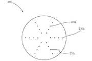
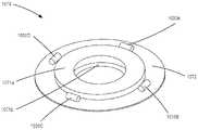
[1057] パッチは、任意の好適な材料から、任意の好適な形状又は構成で形成可能である。例えばパッチは、放射線不透過性ファブリックから、又は、放射線不透過性材料が可撓性材料に埋め込まれた任意の可撓性材料から、形成可能である。追加又は代替として、いくつかの実施形態において、前述の放射線不透過性ビーズなどの放射線不透過性マーカを、パッチに埋め込むことができる。図2は、パッチ200の概略図である。図2に示されるように、パッチ200は円形であり得る。第1のマーカ230A、第2のマーカ230B、及び第3のマーカ230C(本明細書では、集合的に「マーカ230」と呼ばれる)などのマーカは、標的の中心又は星形などの所定のパターンで、パッチ200上に配置され得る。いくつかの実施形態において、マーカ230は、エンドグラフトなどのグラフト内に開窓を作成するための、カッティングテンプレートとして使用可能である。こうした実施形態において、マーカ230のいくつかは、チャード除去ステップの間に、グラフトのカッティング後に廃棄され得る。[1057] The patch can be formed from any suitable material and in any suitable shape or configuration. For example, the patch can be formed from a radiopaque fabric or any flexible material with radiopaque material embedded in the flexible material. Additionally or alternatively, in some embodiments, radiopaque markers, such as the radiopaque beads described above, can be embedded in the patch. FIG. 2 is a schematic diagram of
[1058] いくつかの実施形態において、パッチはリングとして形成可能である。放射線不透過性マーカは、リング内に埋め込むことができる。例えばリング形パッチは、シリコン又は熱可塑性エラストマから形成し、リング形に成形することができる。例えばタングステンなどの放射線不透過性マーカを、リングの外側表面内に埋め込むことができる。いくつかの実施形態において、放射線不透過性マーカを、リングの外側表面に取り付けることができる。いくつかの実施形態において、パッチは円形ドーナツとして形成可能である。円形ドーナツ形パッチは、放射線不透過性材料を含むことができる。例えば、円形ドーナツ形パッチは、ホイル、放射線不透過性ファイバ、又は金属化フィルムから形成可能である。[1058] In some embodiments, the patch can be formed as a ring. A radiopaque marker can be embedded within the ring. For example, a ring-shaped patch can be formed from silicone or a thermoplastic elastomer and molded into a ring shape. A radiopaque marker, such as tungsten, can be embedded within the outer surface of the ring. In some embodiments, radiopaque markers can be attached to the outer surface of the ring. In some embodiments, the patch can be formed as a circular donut. A circular donut-shaped patch can include a radiopaque material. For example, a circular donut-shaped patch can be formed from foil, radiopaque fiber, or metallized film.
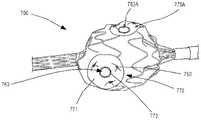
[1059] 図3から図6は、グラフト361と、カッティングのためにグラフト361を硬くするのを支援するため、すり減りを防ぐため、及び/又は、開窓のロケーションをマークするために、グラフト361の所期の開窓のエリアに結合可能な補強部材340(本明細書では、「補強及びマーキングパッチ」とも呼ばれる)とを含む、システムの例の様々な図である。補強及びマーキングパッチ340は、カッティング動作の前又は後にグラフト361に結合可能である。例えば図3は、グラフト361の斜視図である。グラフト361は、例えばエンドグラフトであり得る。図に示されるように、グラフト361は、パイロット穴365、カット367、及びフラップ部分369を含む。グラフト361は、8つのカット367及び8つのフラップ部分369を含むようにカットされているものとして示されているが、グラフト361は任意の好適な数のカット又はフラップ部分を含むことができる。加えて、パイロット穴365及びカット367は、本明細書で説明する任意の好適な方法を介して作成可能である。[1059] FIGS. 3-6 illustrate a
[1060] フラップ部分369がグラフト361の側面に作成された後、フラップ部分369を取り囲むエリアに補強及びマーキングパッチ340を結合することができる。例えば図4は、パッチ340がグラフト361に結合された、グラフト361の一部の拡大図である。パッチ340はリング又はドーナツ形であり得、例えば、接着剤(例えば、感圧接着剤又はシリコン接着剤)、縫合糸、又はグラフト361へのパッチ340の溶接(即ち、溶融)などの、任意の好適な取り付け手段を介して、グラフト361に結合可能である。パッチ340は、カット367のエッジがパッチ340の内側エッジと位置合わせされるように、フラップ部分369に対して配置可能である。パッチ340は、カット367が作成された後にグラフト361に結合されているように説明されるが、パッチ340は、所期のカット367のエリア内でグラフト361の材料を強化するために、カット367の作成前に結合することができる。パッチ340の事前カット適用によって、グラフト361がより容易にカットされるように、グラフト361の補強パッチ340に囲まれたエリア内でのグラフト361の剛性及び/又は緊張を増加させることができる。更に、パッチ340は、パッチ340が放射線イメージングを使用して見えるように、本明細書で説明するパッチのいずれかと同様に、放射線不透過性要素を含み得るか、又は放射線不透過性材料から形成可能である。[1060] After the
[1061] 加えて、フラップ部分369がグラフト361の内部から離れて近位に引っ張られ、グラフト361の外側表面に向かって折り畳まれた後、パッチ340を使用して、フラップ部分369を固定することができる。例えば図5は、フラップ部分369がパッチ340に取り付けられた、グラフト361の一部の拡大図である。図5に示されるように、フラップ部分369は、フラップ部分369がパッチ340の表面に対して平坦であるように折り畳むことが可能であり、結果として開窓363を生じさせる。いくつかの実施形態において、パッチ340は、フラップ部分369がパッチ340と接触するように折り畳まれた後、パッチ340に固定されるように、感圧接着剤でコーティング可能である。いくつかの実施形態において、縫合糸、ステープル、リベット、及びマイクロリベットなどのファスナ(図示せず)を使用して、パッチ340及び/又はグラフト361との確実な関係を築くためにフラップ部分369を縫合することができる。いくつかの実施形態において、感圧接着剤及び/又はファスナは、感圧接着剤又はファスナが放射線イメージングを使用して見えるように、放射線不透過特性を備える材料を含むことができる。更に他の実施形態において、フラップ部分369は、フラップ部分369が図5に示される位置で固定されるように、熱エネルギーを介してパッチ340に固着する(例えば、溶接する)ことができる。[1061] In addition,
[1062] 加えて、フラップ部分369を更に適所に固定するために、任意選択の外側パッチをフラップ部分369及びパッチ340に結合することが可能である。例えば図6は、透明であるように示された外側パッチ342を備えるグラフト361の一部の拡大図である。外側パッチ342は、フラップ部分369がパッチ340と外側パッチ342との間に固定されるように、パッチ340(図5に示される)及びフラップ部分369に結合可能である。外側パッチ342は、フラップ部分369及びパッチ340と接触している外側パッチ342の側面上に接着剤を含むことができる。いくつかの実施形態において、外側パッチ342は、フラップ部分369、パッチ340、及び/又はグラフト361に留める(即ち、縫合糸、ステープル、又はリベットで留める)ことができる。いくつかの実施形態において、接着剤及び/又はファスナは、接着剤又はファスナが放射線イメージングを使用して見えるように、放射線不透過特性を備える材料を含むことができる。更に他の実施形態において、外側パッチ342は、熱エネルギーを介してフラップ部分369、パッチ340、及び/又はグラフト361に固着する(例えば、溶接する)ことができる。更に、外側パッチ342は、外側パッチ342が放射線イメージングを使用して見えるように、本明細書で説明するパッチのいずれかと同様に、放射線不透過性要素を含むか、又は放射線不透過性材料から形成することが可能である。[1062] Additionally, an optional outer patch may be coupled to
[1063] 図示されていないが、いくつかの実施形態において、パッチ340が使用されない場合がある。代わりに、フラップ部分369をグラフト361の外側表面に対して折り畳むことが可能であり、フラップ部分369がグラフト361の外側表面と外側パッチ342との間に挟み込まれるように、外側パッチ342をグラフト361に結合することが可能である。外側パッチ342は、外側パッチ342及びフラップ部分369を適所に固定するために、グラフト361及びフラップ部分369と接触している側面上に接着剤を含むことができる。いくつかの実施形態において、外側パッチ342、フラップ部分369、及びグラフ361を適所に留める(例えば、縫合糸、ステープル、又はリベットで留める)ことが可能である。いくつかの実施形態において、接着剤及び/又はファスナは、接着剤又はファスナが放射線イメージングを使用して見えるように、放射線不透過特性を備える材料を含むことができる。更に他の実施形態において、外側パッチ342、フラップ部分369、及びグラフ361は、溶接を介して適所に固定可能である。[1063] Although not shown, in some embodiments,
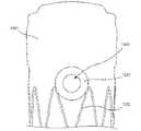
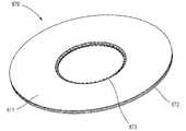
[1064] いくつかの実施形態において、パッチは均一に分散された放射線不透過性材料を含むことができる。例えば図7は、グラフト1361に固定されたパッチ1340の正面図を示す。図7に示されるように、パッチ1340はほぼ円形又はドーナツ形(即ち、リング形)であり、パッチ1340がグラフト1361によって画定される開窓1363と同心であるように、グラフト1361上に配設される。パッチ1340は、パッチ1340が放射線イメージングを介して見えるように、放射線不透過性材料を含む。パッチ1340及び開窓1363の同心位置決めに起因して、患者の体内にグラフト1361を配置する間、放射線イメージングを介して開窓1363のロケーションを識別することができる。例えば、放射線イメージングを使用してパッチ1340を見ながら、開窓1363と患者の分枝動脈とを位置合わせすることが可能である。[1064] In some embodiments, the patch can include a uniformly distributed radiopaque material. For example, FIG. 7 shows a front view of
[1065] いくつかの実施形態において、パッチ1340はポリウレタンを含むことができる。パッチ1340内の放射線不透過性材料は、均一に分散可能であり、例えば、タングステンを含むことができる。いくつかの実施形態において、パッチ1340はグラフト1361のステント支柱1392の上に配設可能である。いくつかの実施形態において、パッチ1340は、パッチ1340がステント支柱1392と重ならないように配設可能である。いくつかの実施形態において、パッチ1340は、パッチ1340がステント支柱1392と重ならないようにカットアウトを含むことができる。いくつかの実施形態において、パッチ1340は可撓性であり得る。パッチ1340は任意の好適な結合方法を介して、及び具体的に言えば、本明細書で説明する任意の好適な結合方法を介して、グラフト1361に固定することができる。例えば、パッチ1340は、グラフト1361に接着結合することができる。いくつかの実施形態において、パッチ1340は、グラフト1361にヘッドボンディング可能である。いくつかの実施形態において、パッチ1340はグラフト1361に縫い付けるか又は他の方法で留めることができる。加えて、パッチ1340は、パッチ340を参照しながら前述したように、開窓1363が作成される前、作成と同時、又は後に、グラフト1361に印加することができる。[1065] In some embodiments, the
[1066] いくつかの実施形態において、補強部材は、可撓性グロメットを形成するために接合される、第1のパッチ及び第2のパッチを含むことができる。可撓性グロメットは、前述と同様に開窓プロセスを介して作成された、エンドグラフトなどのグラフトの1つ以上のマーカ及び/又は1つ以上のフラップ部分を挟み込むように構成可能である。いくつかの実施形態において、1つ以上のマーカをフラップ部分上又は近くに配置することができる。各フラップ部分は、各フラップ部分がフラップ部分とグラフトの外側表面との間に少なくとも1つのマーカを挟み込むように、折り畳むことができる。フラップ部分及び/又はマーカが第1のパッチと第2のパッチとの間に挟み込まれるように、第1のパッチはグラフトの外側表面に固定可能であり、第2のパッチはグラフトの内側表面に固定可能である。第1のパッチ及び第2のパッチは、例えば1本以上の縫合糸又は糸を使用して、相互に及び/又はグラフトに固定可能である。代替として、第1のパッチ及び第2のパッチは、ヒートシーリングなどのシーリングプロセスを介して、相互に及び/又はグラフトに固定可能である。いくつかの実施形態において、アセンブルされた構成では、1つ以上のマーカを、第1のパッチとフラップ部分及び/又はグラフトとの間に、又は第1のパッチと第2のパッチとの間に、配設可能である。[1066] In some embodiments, the reinforcing member can include a first patch and a second patch that are joined to form a flexible grommet. Flexible grommets can be configured to sandwich one or more markers and/or one or more flap portions of a graft, such as an endograft, created through a fenestration process similar to that described above. In some embodiments, one or more markers can be placed on or near the flap portion. Each flap portion can be folded such that each flap portion sandwiches at least one marker between the flap portion and the outer surface of the graft. The first patch is affixable to the outer surface of the graft and the second patch is affixed to the inner surface of the graft such that the flap portions and/or markers are sandwiched between the first patch and the second patch. Can be fixed. The first patch and the second patch can be secured to each other and/or to the graft using, for example, one or more sutures or threads. Alternatively, the first patch and the second patch can be secured to each other and/or to the graft via a sealing process such as heat sealing. In some embodiments, the assembled configuration includes one or more markers between the first patch and the flap portion and/or graft, or between the first patch and the second patch. , can be arranged.
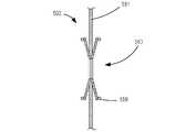
[1067] 図8は、補強部材500(本明細書では「可撓性グロメット」とも呼ばれる)の斜視図の概略図である。可撓性グロメット500は、第1のパッチ562及び第2のパッチ564を含む。第1のパッチ562は第1のワイヤ566を含む。第1のワイヤ566は、放射線不透過性材料から形成される円形マーカワイヤとすることができる。第2のパッチ564は第2のワイヤ568を含む。第2のワイヤ568は、放射線不透過性材料から形成される円形マーカワイヤとすることができる。第2のワイヤ568は、展開前又は展開済みバイアス拡張構成と、展開されていない圧縮構成との間で、グラフトの開窓を介した挿入のために移動可能である。例えば、第2のワイヤ568は、ニチノールなどの形状記憶特性を有する材料から形成可能である。第2のワイヤ568は、第2のワイヤ568の形状及び/又は位置が第2のパッチ564の形状及び/又は位置を制御できるように、例えば、第2のパッチ564の外側エッジに沿って、外側エッジの近くに、及び/又は外側エッジと同心などで、第2のパッチ564に固定(例えば、縫い付け又は埋め込み)可能である。言い換えれば、第2のワイヤ568は圧縮されるように構成可能であるため、展開されていない構成における第2のワイヤ568及び第2のパッチ564は、拡張構成における第2のワイヤ568及び第2のパッチ564が有するよりも小さい直径を有することになる。第1のパッチ562の表面及び第2のパッチ564の表面は、縫い目569に沿って、縫い付けなどの任意の好適な手段を介してヒートボンディング又は接合可能である。いくつかの実施形態において、第1のワイヤ566及び第1のパッチ562は、構造及び/又は機能において第2のワイヤ568及び第2のパッチ564と同一又は同様であり得るため、可撓性グロメット500のいずれかの側は、開窓を介してグラフト内に挿入可能であり、可撓性グロメット500が開窓内で可撓性グラフトに対して固定されるように展開構成へと拡張可能となる。[1067] FIG. 8 is a schematic illustration of a perspective view of a reinforcing member 500 (also referred to herein as a "flexible grommet").
[1068] 図9Aから図9Cは、展開前構成、圧縮構成、及び展開済み構成における、可撓性グロメット500の概略断面図である。図9Aに示されるように、第2のワイヤ568はバイアス拡張構成であり、第2のパッチ564は、グラフトの開窓を介する可撓性グロメット500の挿入前に、ディスク形又はドーナツ形(即ち、リング形)である。図9Bは圧縮構成の可撓性グロメット500を示し、第2のパッチ564がグラフトの開窓を介して挿入できるように、第2のワイヤ568は圧縮されているか又は折り畳まれている。9Cは、展開済み構成の可撓性グロメット500を示し、可撓性グロメット500は、グラフト壁561内の開窓563を介して挿入され、グラフト壁561に固定されている。図9Cに示されるように、第2のワイヤ568を含む第2のパッチ564が開窓563を介して挿入された後、第2のワイヤ568が形状記憶特性を有することに起因して、第2のワイヤ568は自動的に展開済み構成に移行することが可能である。第2のワイヤ568が展開済み構成へと拡張する結果として、可撓性グロメット500はグラフト561に固定される。具体的に言えば、第1のパッチ562は、グラフト561の第1の側面上に位置決めすること及び/又は第1の側面と係合することが可能であり、第2のパッチ564は、グラフト561の第2の側面上に位置決めすること及び/又は第2の側面と係合することが可能である。いくつかの実施形態において、第1のワイヤ566及び/又は第2のワイヤ568は拡張するように構成可能であるため、第1のパッチ562及び/又は第2のパッチ564のパッチに対向する側面は、それぞれ、第1のパッチ562及び/又は第2のパッチ564とグラフト561との間の任意の空間を最小にするために、グラフト561の表面と部分的又は全体的に係合することになる。例えば、第1のワイヤ566及び/又は第2のワイヤ568は拡張するように構成可能であるため、第1のパッチ562及び/又は第2のパッチ564のパッチに対向する側面は、第1のパッチ562及び/又は第2のパッチ564の少なくとも外周の周辺又は付近でグラフト562と接触して配設されることになる。第1のワイヤ566及び/又は第2のワイヤ568が放射線特性を有し、開窓563を取り囲んでいることに起因して、開窓563が放射線イメージングを使用して例えば分枝動脈と位置合わせされるように、グラフト561を患者の体内で位置決めすることができる。[1068] FIGS. 9A-9C are schematic cross-sectional views of a
[1069] いくつかの実施形態において、補強部材は、シリコン層と他のエラストマとの間に放射線不透過性リングが埋め込まれた複合材料を作成するファブリックの上に、シリコン又はウレタンなどの別のエラストマをオーバーモールド成形することによって、形成可能である。補強部材は、リング又はドーナツ形の可撓性パッチとして形成可能である。例えば、図10は、補強部材670(本明細書では、「パッチ」とも呼ばれる)を含むグラフト600の側面図である。パッチ670は、パッチ670内に埋め込まれた放射線不透過性リング又はファイバ630を含むことができる。パッチ670は、糸650を介してグラフト600に固定される。図に示されるように、放射線不透過性リング又はファイバ630は、開窓663のロケーションが放射線イメージングを使用して識別可能なように、グラフト600内の開窓663と同心、及び/又は開窓663を取り囲むように、配置可能である。[1069] In some embodiments, the reinforcing member is another material, such as silicone or urethane, on top of a fabric that creates a composite material with radiopaque rings embedded between the silicone layer and another elastomer. It can be formed by overmolding an elastomer. The reinforcing member can be formed as a ring or a doughnut-shaped flexible patch. For example, FIG. 10 is a side view of a
[1070] いくつかの実施形態において、補強部材は、ファブリックグロメットとして形成可能であり、放射線不透過性リングを包含することができる。図11は、補強部材770(本明細書では、「可撓性グロメット」又は「ファブリックグロメット」とも呼ばれる)を含む、グラフト700の側面図である。図11に示されるように、可撓性グロメット770はファブリックから作ることが可能であり、第1のリング又はドーナツ形ファブリック部分771及び第2のリング又はドーナツ形ファブリック部分(図示せず)を含むことが可能である。第1のドーナツ形ファブリック部分771及び第2のドーナツ形ファブリック部分は、第1のドーナツ形ファブリック部分771及び第2のドーナツ形ファブリック部分の内側表面に沿って、又はそれらの近くに、糸773を介して取り付けることができる。具体的に言えば、第1のドーナツ形ファブリック部分771はグラフト700の外部又は第1の側面上に配設可能であり、第2のドーナツ形ファブリック部分はグラフト700の内部又は第2の側面上に配設可能である。放射線不透過性リング(図示せず)が、第1のドーナツ形ファブリック部分771と第2のドーナツ形ファブリック部分との間に配設可能であり、第1のドーナツ形ファブリック部分771、第2のドーナツ形ファブリック部分、及びグラフト700の開窓763に対して適所に、糸773を介して固定可能である。いくつかの実施形態において、放射線不透過性リングは、第1のドーナツ形ファブリック部分771とグラフト700の外部又は第1の側面との間に配設可能である。いくつかの実施形態において、放射線不透過性リングは、第2のドーナツ形ファブリック部分とグラフト700の内部又は第2の側面との間に配設可能である。糸773が図示及び説明されるが、第1のドーナツ形ファブリック部分771及び第2のドーナツ形ファブリック部分は、接着剤又はヒートボンディングなどの任意の好適な手段を介して取り付け可能である。加えて、任意の好適な数の補強部材をグラフト700に取り付けることができる。例えば図11に示されるように、グラフト700は、第2の開窓763Aに対して取り囲むように固定された、第2の可撓性グロメット770Aを含むことができる。第2の可撓性グロメット770Aは、構造及び/又は機能において可撓性グロメット770と同一又は同様であり得る。したがって、開窓763及び第2の開窓763Aの両方が、各開窓を取り囲む放射線リングに起因して、放射線イメージングを使用して識別可能である。[1070] In some embodiments, the reinforcing member can be formed as a fabric grommet and can include a radiopaque ring. FIG. 11 is a side view of
[1071] いくつかの実施形態において、補強部材はファブリックグロメットとして形成可能であり、放射線不透過性糸の縫合糸を含むことができる。図12は、補強部材870(本明細書では、「可撓性グロメット」又は「ファブリックグロメット」とも呼ばれる)の斜視図である。可撓性グロメット870は、例えばDACRON(登録商標)などのファブリックから作ることが可能であり、第1のリング又はドーナツ形ファブリック部分871及び第2のリング又はドーナツ形ファブリック部分872として形成可能である。第1のリング又はドーナツ形ファブリック部分871及び第2のリング又はドーナツ形ファブリック部分872は、第1のドーナツ形ファブリック部分871及び第2のドーナツ形ファブリック部分872の内側表面に沿って、又はそれらの近くに、縫合糸873を介して取り付けることができる。縫合糸873は、放射線不透過性糸から形成可能である。したがって縫合糸873は、可撓性グロメット870がグラフトの開窓内に固定されるとき、縫合糸がグラフトの開窓のロケーションを示すことができるように、可撓性グロメット870上に位置決め可能である。可撓性グロメット870は、例えばヒートシーリング又は縫合を介して、グラフトに取り付けることができる。いくつかの実施形態において、縫合糸873を使用して、第1のドーナツ形ファブリック部分871を第2のドーナツ形ファブリック部分872に固定すること、及び、ファブリック部分871、872の両方をグラフトに固定することの、両方が可能である。いくつかの実施形態において、第1のドーナツ形ファブリック部分871及び第2のドーナツ形ファブリック部分872のうちの一方又は両方は、可撓性グロメット870が固定される開窓が、放射線イメージングを使用してより容易に識別できるように、全体に均一に分散された放射線物質を有するなどの、放射線材料も含むことが可能である。[1071] In some embodiments, the reinforcing member can be formed as a fabric grommet and can include sutures of radiopaque threads. FIG. 12 is a perspective view of a reinforcing member 870 (also referred to herein as a "flexible grommet" or "fabric grommet").
[1072] いくつかの実施形態において、補強部材は、1つ以上の放射線不透過性要素がグラフトの開窓に対して固定されるように、グラフトに結合された基板として形成可能である。例えば、図13に示されるように、いくつかの離散放射線不透過性要素1530を、グラフト1561内の開窓1563の周辺を取り囲む関係で位置決めすることができる。その後、離散放射線不透過性要素1530が基板1540とグラフト1561との間に挟み込まれるように、離散放射線不透過性要素1530の上に、基板1540を印加すること(例えば、オーバーモールド成形すること)が可能である。加えて、開窓1563を取り囲むグラフト1561のエリアが補強される(例えば、すり減りが低減及び/又は防止される)ように、基板1540をグラフト1561に印加することが可能である。17個の離散放射線不透過性要素1530が示されているが、開窓1563のロケーションを示す任意の好適な数の放射線不透過性要素1530が使用可能である。いくつかの実施形態において、放射線不透過性要素1530は、例えば、金、タンタル、及び/又はプラチナから形成されるか、又はそれらでコーティングされることが可能である。いくつかの実施形態において、基板1540はポリウレタンから形成されるか又はポリウレタンを含むことが可能である。[1072] In some embodiments, the reinforcing member can be formed as a substrate coupled to the graft such that one or more radiopaque elements are secured relative to the fenestrations of the graft. For example, as shown in FIG. 13, a number of discrete
[1073] いくつかの実施形態において、離散放射線不透過性要素及びグラフト上に基板をオーバーモールド成形するのではなく、放射線不透過性コイルリング及びグラフト上に基板をオーバーモールド成形することができる。例えば、図14は、グラフト1461内に画定された開窓1463の周辺を取り囲む関係で配設された放射線不透過性コイル1430を示す。放射線不透過性コイル1430が基板1440とグラフト1461との間に挟み込み及び/又は埋め込みされるように、放射線不透過性基板1440を放射線不透過性コイル1430の上にオーバーモールド成形することができる。いくつかの実施形態において、基板1440は、ポリウレタンから形成されること及び/又はポリウレタンを含むことが可能である。コイル1430が開窓1463を取り囲むことに起因して、放射線イメージングを介して開窓1463のロケーションを識別することができる。いくつかの実施形態において、コイル1430及び/又は基板1440を、グラフト1461のステント支柱1492の上に配設することができる。いくつかの実施形態において、コイル1430及び/又は基板1440がステント支柱1492に重ならないように、コイル1430及び/又は基板1440を、ステント支柱1492の間及び/又はステント支柱1492から少し離して配設することができる。いくつかの実施形態において、熱エネルギーの印加によって基板1440をグラフト1461に固着できるように、基板1440はポリウレタンから形成可能であり、グラフト1461はポリエチレンテレフタレートから形成可能である。[1073] In some embodiments, rather than overmolding the substrate onto the discrete radiopaque element and graft, the substrate may be overmolded onto the radiopaque coil ring and graft. For example, FIG. 14 shows a
[1074] いくつかの実施形態において、放射線不透過性リングがグロメット内に埋め込まれるように、補強部材は、オーバーモールド成形された材料から形成されるグロメットとして形成可能である。例えば、放射線不透過性リングは、DACRON(登録商標)及び/又はシリコンの層間に、オーバーモールド成形プロセスを介して埋め込むことができる。いくつかの実施形態において、シリコン及び他のエラストマの層間に放射線不透過性リングが埋め込まれたファブリックの上に、シリコン又は、ウレタンなどの別のエラストマをオーバーモールド成形することによって、可撓性グロメットが形成可能である。[1074] In some embodiments, the reinforcing member can be formed as a grommet formed from an overmolded material such that the radiopaque ring is embedded within the grommet. For example, a radiopaque ring can be embedded between layers of DACRON® and/or silicon via an overmolding process. In some embodiments, the flexible grommet is made by overmolding silicone or another elastomer, such as urethane, over a fabric with radiopaque rings embedded between layers of silicone and other elastomers. can be formed.
[1075] いくつかの実施形態において、補強部材がシリコングロメットとして形成可能である。例えば図15は、何枚かのリーフがグラフト400の内側に位置決めされるように構成され、何枚かのリーフがグラフト400の外側に位置決めされるように構成され、それによってリーフ間にグラフト400が挟み込まれる、補強部材470(本明細書では、「リーフグロメット」とも呼ばれる)を含む、グラフト400の側面図である。リーフグロメット470は、リーフグロメット470内に埋め込まれた1つ以上のマーカ430を含む。1つ以上のマーカ430は離散マーカとして示されているが、いくつかの実施形態において、リーフグロメット470は放射線不透過性リングとして形成されるマーカ430を含むことが可能である。リーフグロメット470は、糸450を含む1つ以上の結び目及び/又は接着剤を介してグラフト400に固定することができる。加えて、リーフグロメット470は、図16を参照しながら下記で説明するリーフグロメット970と同一又は同様の構造及び/又は機能を有することが可能である。[1075] In some embodiments, the reinforcing member can be formed as a silicone grommet. For example, FIG. 15 illustrates that some leaves are configured to be positioned inside
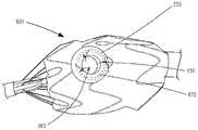
[1076] 図16は、補強部材970(本明細書では、「グロメット」とも呼ばれる)の斜視図である。グロメット970は、図15を参照しながら上記で説明したリーフグロメット470と同一又は同様の構造及び/又は機能を有し得る。グロメット970は、第1の部分971及び第2の部分972を含むことができる。第1の部分971及び第2の部分972は、シリコンから形成可能である。第1の部分971は、ドーナツ又はリング形のベース974aと、ベースから延在するいくつかの突出部分975aとを含むことができる。同様に、第2の部分972は、ドーナツ又はリング形のベース974bと、ベースから延在するいくつかの突出部分975bとを含むことができる。第1の部分971及び第2の部分972は、各々3つの突出部分を含むように示されているが、第1の部分971及び第2の部分972は任意の好適な数の突出部分を含むことができる。第1の部分971の突出部分975a及び第2の部分972の突出部分975bは、相互に放射状にオフセット可能であるため、突出部分975bはグラフトの内側に位置決め可能であり、突出部分975aはグラフトの外側に位置決め可能であり、それによってグラフトを挟み込み、グロメット970をグラフトの開窓に対して適所に固定するようになっている。[1076] FIG. 16 is a perspective view of a reinforcing member 970 (also referred to herein as a "grommet").
[1077] グロメット970は、グロメット970の中心(及びしたがって、グロメット970が取り付けられるグラフトの開窓)が、放射線イメージングを使用して識別可能なように、第1の部分971と第2の部分972との間に挟み込まれた放射線不透過性リング930を含むことが可能である。いくつかの実施形態において、シリコングロメットは、放射線不透過性糸及び/又は放射線不透過性ビーズを含むことが可能であり、及び/又は、放射線不透過性材料で形成可能である。グロメット970は、縫合糸、ヒートボンディング、リベット、及び/又は、本明細書で説明する任意の他の好適な取り付け手段を介して、グラフトに取り付けることができる。いくつかの実施形態において、グロメット970は、開窓が作成される前又は後のいずれかに、開窓を取り囲むグラフトのエリアを補強することが可能である。グロメット970はシリコンから形成されるものとして説明されるが、いくつかの実施形態において、グロメットは、エラストマポリウレタン又はポリアミドなどの任意の他の好適な材料から形成可能である。加えて、グロメットは、リング形ベース及び突出部を有するものとして形状化されるように示されているが、グロメットは任意の好適な形状とすることができる。例えば、グロメットはOリング(すなわち、リング形ベースを有するが突出部はない)と同様に形状化可能である。[1077] The
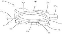
[1078] いくつかの実施形態において、補強部材は、ファブリック、放射線不透過性要素、及びファブリック上にオーバーモールド成形されるエラストマ材料の組み合わせを含む、グロメットとして形成可能である。例えば図17は、補強部材1070(本明細書では、「グロメット」とも呼ばれる)の斜視図である。グロメット1070は、第1の部分1071a、第2の部分1071b、及び第3の部分1072を含むことができる。第1の部分1071a及び第2の部分1071bは、例えばシリコンから形成可能である。第3の部分1072は、例えばDACRON(登録商標)などのファブリックから形成可能である。第1の部分1071a、第2の部分1071b、及び第3の部分1072は、各々、中央開口を備える円形ディスクとして形状化可能である。第1の部分1071a及び第2の部分1071bは、第1の部分1071a、第2の部分1071b、及び第3の部分1072の開口が軸方向に位置合わせされるように、第3の部分1072を挟み込むように配置可能である。グロメット1070は、第1の放射線不透過性要素1030A、第2の放射線不透過性要素1030B、第3の放射線不透過性要素1030C、及び第4の放射線不透過性要素1030D(本明細書では、集合的に「放射線不透過性要素1030」と呼ばれる)を含むことができる。図17では、4つの放射線不透過性要素1030が説明及び図示されているが、任意の好適な数の放射線不透過性要素1030を含むことができる。放射線不透過性要素1030は、例えば、リング又はビーズなどの任意の好適な形状の1つ以上のマーカを含むことができる。放射線不透過性要素1030は、例えば接着剤又は縫合糸を介して、第3の部分1072に固定可能である。いくつかの実施形態において、放射線不透過性要素1030は、第1の部分1071aと第3の部分1072との間、及び/又は、第2の部分1071bと第3の部分1072との間に、埋め込むことができる。例えば、エラストマとファブリックとの間に放射線不透過性要素1030が埋め込まれるように、第1の部分1071a及び/又は第2の部分1071bのエラストマ材料を、第3の部分1072のファブリックにオーバーモールド成形することが可能である。グロメット1070は、例えばヒートシーリング又は縫合を介して、エンドグラフトなどのグラフトに取り付けることができる。グロメット1070は、第1の部分1071a及び/又は第3の部分1072がグラフトに直接固定され、第2の部分1071bがグラフトの開窓内に配設されるように、グラフトに取り付けることができる。第2の部分1071bは、グラフトの開窓の形状及びサイズが維持されるようにグラフトの開窓の形状及びサイズに対応するために、及び/又は、グラフトの開窓の形状及びサイズをマークするために、形状及びサイズを決定することができる。いくつかの実施形態において、第1の部分1071a及び/又は第2の部分1071bは、放射線不透過性添加剤を含むことができる。例えば、放射線不透過性添加剤は、第1の部分1071a及び/又は第2の部分1071b全体に均一に分散可能である。[1078] In some embodiments, the reinforcing member can be formed as a grommet that includes a combination of a fabric, a radiopaque element, and an elastomeric material overmolded onto the fabric. For example, Figure 17 is a perspective view of a reinforcing member 1070 (also referred to herein as a "grommet"). The
[1079] いくつかの実施形態において、補強部材が、グラフト内の開窓をマーク及び/又は補強するために使用される圧着装置として形成可能である。例えば図18は、補強部材1180(本明細書では、「圧着装置」とも呼ばれる)の概略図である。圧着装置1180は、圧着構造1182及びワイヤ又はケーブル1184を含むことができる。圧着構造1182は、例えばレーザカッティングを介してシムストックから形成可能である。圧着構造1182は、圧着構造1182が開窓を取り囲むグラフト(例えば、DACRON(登録商標)ファブリックから形成されるグラフト)のエリア上へと圧着可能なように、ワイヤ1184の周辺で圧着可能又は折り畳み可能とすることができる。ワイヤ1184は、ワイヤ1184が放射線イメージングを使用して視覚化可能なように、放射線不透過性材料を含むことができる。圧着構造1182は、外側タブ(例えば、第1の外側タブ1186A及び第2の外側タブ1186B(本明細書では、集合的に「外側タブ1186」と呼ばれる))及び内側タブ(例えば、第1の内側タブ1188A及び第2の内側タブ1188B(本明細書では、集合的に「内側タブ1188」と呼ばれる))を含むことができる。内側タブ1188は、グラフトに圧着装置を適用する際に、グラフトが外側タブ1186と内側タブ1188との間に固定され、ワイヤ1184が開窓のロケーションを取り囲む、及び/又は指定するように、開窓を介して外側タブ1186に対して折り畳むことが可能である。圧着装置1180は、任意の好適な数の外側タブ1186及び内側タブ1188を含むことができる。[1079] In some embodiments, the reinforcing member can be formed as a crimping device that is used to mark and/or reinforce the fenestrations in the graft. For example, Figure 18 is a schematic diagram of a reinforcing member 1180 (also referred to herein as a "crimping device"). Crimping
[1080] いくつかの実施形態において、補強部材は、グラフト内の開窓の両側に位置決めされるように、及び、グラフト内の開口を介して相互に取り付けられるように構成された、外側要素及び内側要素を含むことができる。外側要素は、例えばエラストマ材料から形成可能である。外側要素は、例えばプラスチックから形成可能な離散剛性接続機構を含むことができる。内側要素は、放射線不透過性金属リングとして形成可能であり、外側要素の接続機構に対応する離散剛性接続機構を含むことができる。外側要素の接続機構及び内側要素の接続機構は、グラフト内の穴と位置合わせ可能であり、例えば超音波溶接を使用して相互に取り付け可能である。いくつかの実施形態において、グラフト内の開口は、グラフト内に開窓が作成されるのと同時に作成可能である。他の実施形態において、開口は、外側要素及び内側要素のグラフトへの取り付けと同時に作成可能である。[1080] In some embodiments, the reinforcing member comprises an outer element and an outer element configured to be positioned on opposite sides of a fenestration in the graft and attached to each other through an opening in the graft. An inner element can be included. The outer element can be made of, for example, an elastomeric material. The outer element can include discrete rigid connections that can be formed from plastic, for example. The inner element can be formed as a radiopaque metal ring and can include discrete rigid connections corresponding to those of the outer element. The attachment features of the outer element and the attachment features of the inner element can be aligned with holes in the graft and attached to each other using, for example, ultrasonic welding. In some embodiments, openings in the graft can be created at the same time fenestrations are created in the graft. In other embodiments, the opening can be created simultaneously with attachment of the outer and inner elements to the graft.
[1081] いくつかの実施形態において、補強部材は、グラフト内の開窓の両側で位置決めされるように、及び、スナップ機構を介し、グラフト内の開口を介して相互に取り付けられるように構成された、外側要素及び内側要素を含むことができる。例えば、図19Aは、補強部材1270(本明細書では、「マーキング及び補強アセンブリ」又は「アセンブリ」とも呼ばれる)の斜視図である。アセンブリ1270は、外側要素1271及び内側要素1272を含む。外側要素1271は、スナップ機構1276を含む。4つのスナップ機構1276が示されているが、任意の好適な数のスナップ機構を含むことができる。スナップ機構1276は、ステム部分及び円錐部分を含むことができる。円錐部分はステム部分よりも大きな直径を有し得、ステップ部分から離れるほど先細りし得る。外側要素1271の斜視図である図19Bに示されるように、スナップ機構1276は、スナップ機構1276が別の材料内の開口を介して挿入可能であるが、いったん挿入されると、開口を介して引き抜くことはできないように、形状及びサイズを決定することができる。外側要素1271は、例えば、可撓性エラストマ材料から形成可能である。内側要素1272の斜視図である図19Cに示されるように、内側要素1272は、スナップ機構1276が開口1277を通過できるが、いったん内側要素1272と完全に係合すると開口1277から引き抜くことはできないように、形状及びサイズが決定された開口1277を画定することができる。内側要素1272は、例えばレーザカットシムとすることができる。内側要素1272は、外側要素1271よりも剛性であり得る。いくつかの実施形態において、グラフト内の開口は、グラフト内に開窓が作成されるのと同時に作成可能である。他の実施形態において、開口は、外側要素及び内側要素をグラフトに取り付けるのと同時に作成可能である。いくつかの実施形態において、内側要素1272及び/又は外側要素1271は、放射線不透過性材料から形成可能であるか、又は、放射線不透過性ビーズ又は糸などの離散放射線不透過性要素を含むことができる。[1081] In some embodiments, the reinforcing members are configured to be positioned on opposite sides of a fenestration in the graft and attached to each other through openings in the graft via a snap mechanism. It can also include an outer element and an inner element. For example, Figure 19A is a perspective view of a reinforcing member 1270 (also referred to herein as a "marking and reinforcing assembly" or "assembly").
[1082] いくつかの実施形態において、方法1600は、1602で、患者特有の人工装具内に開窓を生成することを含む。方法1600は、本明細書で説明する補強部材のいずれかで使用可能である。開窓は、患者の血管の一部における分枝血管のロケーションに対応可能である。方法1600は、1604で、患者特有の人工装具にマーカを結合することを更に含むことができる。マーカは、パッチが開窓を取り囲むように、患者特有の人工装具に固定するように構成された部材を含むことができる。マーカは、放射線イメージングを介して開窓のロケーションを示すように構成された、少なくとも1つの放射線不透過性要素を含むこともできる。いくつかの実施形態において、患者特有の人工装具にマーカを結合することは、開窓の生成に先立って実行される。いくつかの実施形態において、患者特有の人工装具にマーカを結合することは、開窓の生成の後に実行される。いくつかの実施形態において、結合することは、熱エネルギーをマーカ及び患者特有の人工装具に印加することを含む。いくつかの実施形態において、マーカ及び患者特有の人工装具は、どちらもポリエチレンテレフタレートを含む。いくつかの実施形態において、結合することは、少なくとも1つの放射線不透過性要素及び患者特有の人工装具上に部材をオーバーモールド成形することを含む。いくつかの実施形態において、マーカを患者特有の人工装具に結合することは、開窓を生成することと同時に実行される。任意選択として、方法1600は、1606で、マーカが放射線イメージングを使用して分枝血管のロケーションと位置合わせするように、患者の体内で患者特有の人工装具を位置決めすることを更に含み得る。[1082] In some embodiments, the
[1083] 以上、システム、方法、及びデバイスの様々な実施形態について説明してきたが、それらは単なる例として提示されたものであり、制限ではないことを理解されよう。前述の方法及びステップはある順序で発生するあるイベントを示すが、本開示の恩恵を受ける当業者であれば、あるステップの順序は改変可能であり、こうした改変は本発明の変形形態に従うものであることを理解されよう。加えて、あるステップは、可能であれば並列プロセスにおいて同時に実行され得、並びに前述の順序で実行され得る。実施形態を詳細に図示及び説明してきたが、形式及び細部における様々な変更が実行され得ることを理解されよう。[1083] While various embodiments of systems, methods, and devices have been described above, it is to be understood that they have been presented by way of example only, and not limitation. Although the methods and steps described above show certain events occurring in a certain order, the order of certain steps can be modified by one of ordinary skill in the art having the benefit of this disclosure, and such modifications are consistent with variations of the invention. It should be understood that there is Additionally, certain steps may be performed concurrently in parallel processes when possible, as well as performed in the order described. While the embodiments have been illustrated and described in detail, it will be appreciated that various changes in form and detail may be practiced.
[1084] 例えば、構成要素の特定の特徴及び/又は組み合わせを有するものとして様々な実施形態を説明してきたが、本明細書で説明する実施形態のいずれかからの任意の特徴及び/又は構成要素の任意の組み合わせ又は副組み合わせを有する他の実施形態が可能である。更に、様々な構成要素の特定の構成も変更可能である。例えば、様々な構成要素のサイズ及び特定の形状は図示された実施形態とは異なる可能性があるが、依然として本明細書で説明する機能を提供している。
[1084] For example, while various embodiments have been described as having particular features and/or combinations of components, any feature and/or component from any of the embodiments described herein Other embodiments are possible with any combination or subcombination of . In addition, the specific arrangement of various components may also vary. For example, the sizes and specific shapes of various components may differ from the illustrated embodiments while still providing the functionality described herein.
Claims (8)
Translated fromJapaneseb)内側エッジを画定するリング形パッチ(340)であって、前記グラフトの前記フラップ部分を取り囲むエリアに結合される、リング形パッチ(340)と、
c)前記フラップ部分及び前記リング形パッチに結合される外側パッチと、
を備え、それによって更に前記フラップ部分を適所に固定する、
システム。a) a graft (361) having inner and outer surfaces, the graft (361) including a flap portion (369) defining a pilot hole (365) and a cut (367);
b) a ring-shaped patch (340) defining an inner edge, said ring-shaped patch (340) being coupled to an area surrounding said flap portion of said graft;
c) an outer patch coupled to said flap portion and said ring-shaped patch;
thereby further securing the flap portion in place ;
system.
前記外側パッチは、フラップ部分、前記パッチ、及び前記グラフトの少なくとも1つに留められる、請求項1に記載のシステム。further comprising a fastener;
2. The system of claim1 , wherein the outer patch is secured to at least one of the flap portion, the patch, and the graft.
Applications Claiming Priority (2)
| Application Number | Priority Date | Filing Date | Title |
|---|---|---|---|
| US201662349287P | 2016-06-13 | 2016-06-13 | |
| US62/349,287 | 2016-06-13 |
Related Parent Applications (1)
| Application Number | Title | Priority Date | Filing Date |
|---|---|---|---|
| JP2018564736ADivisionJP6841848B2 (en) | 2016-06-13 | 2017-06-13 | Systems, devices and methods for marking and / or reinforcing fenestrations in prosthetic implants |
Publications (2)
| Publication Number | Publication Date |
|---|---|
| JP2021079140A JP2021079140A (en) | 2021-05-27 |
| JP7167209B2true JP7167209B2 (en) | 2022-11-08 |
Family
ID=59093638
Family Applications (2)
| Application Number | Title | Priority Date | Filing Date |
|---|---|---|---|
| JP2018564736AActiveJP6841848B2 (en) | 2016-06-13 | 2017-06-13 | Systems, devices and methods for marking and / or reinforcing fenestrations in prosthetic implants |
| JP2021024175AActiveJP7167209B2 (en) | 2016-06-13 | 2021-02-18 | Systems, devices and methods for marking and/or reinforcing fenestrations in prosthetic implants |
Family Applications Before (1)
| Application Number | Title | Priority Date | Filing Date |
|---|---|---|---|
| JP2018564736AActiveJP6841848B2 (en) | 2016-06-13 | 2017-06-13 | Systems, devices and methods for marking and / or reinforcing fenestrations in prosthetic implants |
Country Status (7)
| Country | Link |
|---|---|
| US (2) | US10987235B2 (en) |
| EP (2) | EP3903732B1 (en) |
| JP (2) | JP6841848B2 (en) |
| CN (1) | CN109803607B (en) |
| AU (1) | AU2017285041A1 (en) |
| ES (1) | ES2860458T3 (en) |
| WO (1) | WO2017218474A1 (en) |
Families Citing this family (34)
| Publication number | Priority date | Publication date | Assignee | Title |
|---|---|---|---|---|
| JP6227542B2 (en) | 2011-11-11 | 2017-11-08 | ボルトン メディカル インコーポレイテッド | Universal endovascular graft |
| CN106420107B (en) | 2011-11-16 | 2019-02-05 | 波顿医疗公司 | The device and method of reparation for aortic branch blood vessel |
| BR112017005790A2 (en) | 2014-09-23 | 2018-01-30 | Bolton Medical Inc | vascular repair devices and methods of use |
| CN107949346B (en) | 2015-07-08 | 2020-09-04 | 主动脉公司 | Apparatus and method for anatomical mapping of a prosthetic implant |
| ES2830748T3 (en) | 2016-04-05 | 2021-06-04 | Bolton Medical Inc | Stent grafting with internal tunnels and fenestrations |
| ES2905193T3 (en) | 2016-05-25 | 2022-04-07 | Bolton Medical Inc | Stent grafts for the treatment of aneurysms |
| EP3903732B1 (en) | 2016-06-13 | 2025-07-30 | Bolton Medical, Inc. | Devices for reinforcing fenestrations in prosthetic implants |
| AU2017306141A1 (en) | 2016-08-02 | 2019-03-07 | Aortica Corporation | Systems, devices, and methods for coupling a prosthetic implant to a fenestrated body |
| US10537419B2 (en)* | 2016-10-27 | 2020-01-21 | Cook Medical Technologies Llc | Prosthesis with branched portion |
| WO2018156849A1 (en) | 2017-02-24 | 2018-08-30 | Bolton Medical, Inc. | Vascular prosthesis with fenestration ring and methods of use |
| EP3534837A1 (en) | 2017-02-24 | 2019-09-11 | Bolton Medical, Inc. | Constrainable stent graft, delivery system and methods of use |
| WO2018156851A1 (en) | 2017-02-24 | 2018-08-30 | Bolton Medical, Inc. | Vascular prosthesis with moveable fenestration |
| WO2018156847A1 (en) | 2017-02-24 | 2018-08-30 | Bolton Medical, Inc. | Delivery system and method to radially constrict a stent graft |
| EP3932373B1 (en) | 2017-02-24 | 2022-12-21 | Bolton Medical, Inc. | Delivery system for radially constricting a stent graft |
| WO2018156850A1 (en) | 2017-02-24 | 2018-08-30 | Bolton Medical, Inc. | Stent graft with fenestration lock |
| ES2863978T3 (en) | 2017-02-24 | 2021-10-13 | Bolton Medical Inc | System for radially constricting a stent graft |
| WO2018156854A1 (en) | 2017-02-24 | 2018-08-30 | Bolton Medical, Inc. | Radially adjustable stent graft delivery system |
| WO2018156848A1 (en) | 2017-02-24 | 2018-08-30 | Bolton Medical, Inc. | Vascular prosthesis with crimped adapter and methods of use |
| ES2954897T3 (en) | 2017-02-24 | 2023-11-27 | Bolton Medical Inc | Constrained Wrap Stent Graft Delivery System |
| JP7271510B2 (en) | 2017-09-25 | 2023-05-11 | ボルトン メディカル インコーポレイテッド | Systems, devices and methods for coupling prosthetic implants to fenestrated bodies |
| CN110121319B (en) | 2017-10-31 | 2023-05-09 | 波顿医疗公司 | Distal torque component, delivery system, and method of use thereof |
| US20200100889A1 (en)* | 2018-10-02 | 2020-04-02 | Cook Medical Technologies Llc | Radiopacity modulated radiopaque marker and stent graft using same |
| JP7277988B2 (en)* | 2018-11-14 | 2023-05-19 | サナメディ株式会社 | Stent graft with fenestration |
| JP7304031B2 (en)* | 2019-05-07 | 2023-07-06 | 学校法人早稲田大学 | stent graft |
| CN110236748B (en)* | 2019-05-30 | 2021-03-26 | 中国人民解放军陆军军医大学第一附属医院 | Exempt from to make accurate external windowing aortic support of order |
| US11806225B2 (en) | 2019-06-27 | 2023-11-07 | Lifetech Scientific (Shenzhen) Co. Ltd. | Covered stent |
| CN112438823A (en)* | 2019-08-30 | 2021-03-05 | 陈兵 | Preset windowing covered stent and preset windowing covered stent system |
| US11191634B2 (en) | 2019-11-07 | 2021-12-07 | Cook Medical Technologies Llc | Aortic stent graft with durable suture attachment sites |
| EP4110415B1 (en)* | 2020-02-26 | 2023-11-29 | C. R. Bard, Inc. | Stent grafts having a radiopaque marker and methods of producing |
| EP4247298A4 (en)* | 2020-11-23 | 2024-09-25 | Massachusetts Institute of Technology | DEVICE AND METHOD FOR WINDOW ALIGNMENT |
| IT202100000128A1 (en)* | 2021-01-07 | 2022-07-07 | Luca Rubino | METHOD FOR THE CREATION OF CUSTOMIZED AORTIC STENT GRAFTS AND ASSOCIATED POSITIONING DEVICE |
| WO2022265985A1 (en) | 2021-06-14 | 2022-12-22 | Bolton Medical, Inc. | Support ring, aortic prosthesis and method of forming |
| WO2022265989A1 (en) | 2021-06-14 | 2022-12-22 | Bolton Medical, Inc. | Support ring vascular aortic repair and methods of use |
| CN115813551B (en)* | 2022-11-24 | 2024-06-11 | 株洲茂物医疗科技有限公司 | Special bracket for external windowing and application method thereof |
Citations (4)
| Publication number | Priority date | Publication date | Assignee | Title |
|---|---|---|---|---|
| US4041931A (en) | 1976-05-17 | 1977-08-16 | Elliott Donald P | Radiopaque anastomosis marker |
| JP2002301083A (en) | 2001-04-09 | 2002-10-15 | Nec Tokin Corp | Vascular anastomosis instrument |
| JP2012152549A (en) | 2011-01-25 | 2012-08-16 | Confluent Surgical Inc | Hemostasis patch |
| JP2015527156A (en) | 2012-09-11 | 2015-09-17 | ユニヴェルシテ・ドゥ・ストラスブール | TREATMENT KIT, TREATMENT DEVICE, AND MANUFACTURING METHOD THEREOF |
Family Cites Families (216)
| Publication number | Priority date | Publication date | Assignee | Title |
|---|---|---|---|---|
| US2339187A (en)* | 1941-09-26 | 1944-01-11 | Pain Herbert | Towel or cloth holder |
| US3099855A (en)* | 1962-02-01 | 1963-08-06 | Johnson & Johnson | Cleaning implement |
| US4787391A (en)* | 1985-06-17 | 1988-11-29 | Elefteriades John A | Anastomotic marking device and related method |
| US5123917A (en) | 1990-04-27 | 1992-06-23 | Lee Peter Y | Expandable intraluminal vascular graft |
| FR2688401B1 (en) | 1992-03-12 | 1998-02-27 | Thierry Richard | EXPANDABLE STENT FOR HUMAN OR ANIMAL TUBULAR MEMBER, AND IMPLEMENTATION TOOL. |
| US5370692A (en) | 1992-08-14 | 1994-12-06 | Guild Associates, Inc. | Rapid, customized bone prosthesis |
| US5356432B1 (en)* | 1993-02-05 | 1997-02-04 | Bard Inc C R | Implantable mesh prosthesis and method for repairing muscle or tissue wall defects |
| US5607444A (en)* | 1993-12-02 | 1997-03-04 | Advanced Cardiovascular Systems, Inc. | Ostial stent for bifurcations |
| US5507769A (en) | 1994-10-18 | 1996-04-16 | Stentco, Inc. | Method and apparatus for forming an endoluminal bifurcated graft |
| US5713948A (en) | 1995-07-19 | 1998-02-03 | Uflacker; Renan | Adjustable and retrievable graft and graft delivery system for stent-graft system |
| CA2244080A1 (en)* | 1996-02-02 | 1997-08-07 | Transvascular, Inc. | Methods and apparatus for blocking flow through blood vessels |
| US5676670A (en)* | 1996-06-14 | 1997-10-14 | Beth Israel Deaconess Medical Center | Catheter apparatus and method for creating a vascular bypass in-vivo |
| EP1595513A3 (en) | 1996-06-20 | 2010-09-15 | Vascutek Limited | Prosthetic repair of body passages |
| US7220275B2 (en)* | 1996-11-04 | 2007-05-22 | Advanced Stent Technologies, Inc. | Stent with protruding branch portion for bifurcated vessels |
| US6599316B2 (en)* | 1996-11-04 | 2003-07-29 | Advanced Stent Technologies, Inc. | Extendible stent apparatus |
| US6036702A (en)* | 1997-04-23 | 2000-03-14 | Vascular Science Inc. | Medical grafting connectors and fasteners |
| AUPO700897A0 (en) | 1997-05-26 | 1997-06-19 | William A Cook Australia Pty Ltd | A method and means of deploying a graft |
| US5984955A (en)* | 1997-09-11 | 1999-11-16 | Wisselink; Willem | System and method for endoluminal grafting of bifurcated or branched vessels |
| US6030414A (en)* | 1997-11-13 | 2000-02-29 | Taheri; Syde A. | Variable stent and method for treatment of arterial disease |
| AUPP083597A0 (en)* | 1997-12-10 | 1998-01-08 | William A Cook Australia Pty Ltd | Endoluminal aortic stents |
| US5910144A (en) | 1998-01-09 | 1999-06-08 | Endovascular Technologies, Inc. | Prosthesis gripping system and method |
| US6395018B1 (en)* | 1998-02-09 | 2002-05-28 | Wilfrido R. Castaneda | Endovascular graft and process for bridging a defect in a main vessel near one of more branch vessels |
| US6352543B1 (en)* | 2000-04-29 | 2002-03-05 | Ventrica, Inc. | Methods for forming anastomoses using magnetic force |
| US6171334B1 (en) | 1998-06-17 | 2001-01-09 | Advanced Cardiovascular Systems, Inc. | Expandable stent and method of use |
| US6059824A (en)* | 1998-12-23 | 2000-05-09 | Taheri; Syde A. | Mated main and collateral stent and method for treatment of arterial disease |
| GB2365356A (en) | 1999-05-07 | 2002-02-20 | Salviac Ltd | An embolic protection device |
| AU5143000A (en)* | 1999-05-18 | 2000-12-05 | Vascular Innovations, Inc. | Implantable medical device such as an anastomosis device |
| EP1400204A1 (en)* | 1999-08-05 | 2004-03-24 | Broncus Technologies, Inc. | Methods and devices for creating collateral channels in the lungs |
| US20020198585A1 (en)* | 1999-10-05 | 2002-12-26 | Willem Wisselink | System and method for edoluminal grafting of bifurcated or branched vessels |
| US6610087B1 (en) | 1999-11-16 | 2003-08-26 | Scimed Life Systems, Inc. | Endoluminal stent having a matched stiffness region and/or a stiffness gradient and methods for providing stent kink resistance |
| AU3826601A (en) | 2000-02-15 | 2001-08-27 | Eva Corp | Temporary stent assembly for use in a surgical procedure |
| US7226474B2 (en) | 2000-05-01 | 2007-06-05 | Endovascular Technologies, Inc. | Modular graft component junctions |
| US6610006B1 (en)* | 2000-07-25 | 2003-08-26 | C. R. Bard, Inc. | Implantable prosthesis |
| US6585762B1 (en) | 2000-08-10 | 2003-07-01 | Paul Stanish | Arteriovenous grafts and methods of implanting the same |
| US7840393B1 (en) | 2000-10-04 | 2010-11-23 | Trivascular, Inc. | Virtual prototyping and testing for medical device development |
| US6582394B1 (en)* | 2000-11-14 | 2003-06-24 | Advanced Cardiovascular Systems, Inc. | Stent and catheter assembly and method for treating bifurcated vessels |
| US8870946B1 (en)* | 2000-12-11 | 2014-10-28 | W.L. Gore & Associates, Inc. | Method of deploying a bifurcated side-access intravascular stent graft |
| US20020095205A1 (en)* | 2001-01-12 | 2002-07-18 | Edwin Tarun J. | Encapsulated radiopaque markers |
| WO2002054989A2 (en) | 2001-01-15 | 2002-07-18 | Terumo Corp | Stent |
| US20040102866A1 (en) | 2001-01-29 | 2004-05-27 | Harris Simon James | Modelling for surgery |
| US6761733B2 (en) | 2001-04-11 | 2004-07-13 | Trivascular, Inc. | Delivery system and method for bifurcated endovascular graft |
| US6821291B2 (en) | 2001-06-01 | 2004-11-23 | Ams Research Corporation | Retrievable stent and method of use thereof |
| US20020193872A1 (en)* | 2001-06-18 | 2002-12-19 | Trout Hugh H. | Prosthetic graft assembly and method of use |
| AUPR847201A0 (en)* | 2001-10-26 | 2001-11-15 | Cook Incorporated | Endoluminal graft |
| WO2003088820A2 (en)* | 2002-04-19 | 2003-10-30 | Broncus Technologies, Inc. | Devices for maintaining surgically created openings |
| US20040117003A1 (en) | 2002-05-28 | 2004-06-17 | The Cleveland Clinic Foundation | Minimally invasive treatment system for aortic aneurysms |
| US20040034406A1 (en)* | 2002-08-19 | 2004-02-19 | Thramann Jeffrey J. | Vascular stent grafts |
| US20040059406A1 (en)* | 2002-09-20 | 2004-03-25 | Cully Edward H. | Medical device amenable to fenestration |
| AU2003270817B2 (en) | 2002-09-26 | 2009-09-17 | Vactronix Scientific, Llc | High strength vacuum deposited nitionol alloy films, medical thin film graft materials and method of making same |
| US7326242B2 (en)* | 2002-11-05 | 2008-02-05 | Boston Scientific Scimed, Inc. | Asymmetric bifurcated crown |
| US9125733B2 (en)* | 2003-01-14 | 2015-09-08 | The Cleveland Clinic Foundation | Branched vessel endoluminal device |
| JP4566988B2 (en) | 2003-04-02 | 2010-10-20 | ボストン サイエンティフィック リミテッド | Separable and recoverable stent assembly |
| US7112216B2 (en) | 2003-05-28 | 2006-09-26 | Boston Scientific Scimed, Inc. | Stent with tapered flexibility |
| US8002740B2 (en)* | 2003-07-18 | 2011-08-23 | Broncus Technologies, Inc. | Devices for maintaining patency of surgically created channels in tissue |
| US8808351B2 (en)* | 2003-10-10 | 2014-08-19 | Cook Medical Technologies Llc | Stretchable prosthesis fenestration |
| US7425219B2 (en)* | 2003-10-10 | 2008-09-16 | Arshad Quadri | System and method for endoluminal grafting of bifurcated and branched vessels |
| DE602004018169D1 (en) | 2003-10-10 | 2009-01-15 | Cook William Europ | STENT WINDOW |
| ATE392865T1 (en)* | 2003-10-10 | 2008-05-15 | Cook William A Australia | STENT IMPLANTS WITH WINDOWS |
| US20050096725A1 (en) | 2003-10-29 | 2005-05-05 | Pomeranz Mark L. | Expandable stent having removable slat members |
| EP3424463A1 (en)* | 2003-11-08 | 2019-01-09 | Cook Medical Technologies LLC | Aorta and branch vessel stent grafts and system |
| US8048140B2 (en) | 2004-03-31 | 2011-11-01 | Cook Medical Technologies Llc | Fenestrated intraluminal stent system |
| US7758626B2 (en) | 2004-07-20 | 2010-07-20 | Medtronic Vascular, Inc. | Device and method for delivering an endovascular stent-graft having a longitudinally unsupported portion |
| DE102004044435A1 (en) | 2004-09-14 | 2006-03-30 | Siemens Ag | Method and device for diagnosis and therapy of the aortic aneurysm |
| US20060058867A1 (en)* | 2004-09-15 | 2006-03-16 | Thistle Robert C | Elastomeric radiopaque adhesive composite and prosthesis |
| DE602005024585D1 (en) | 2004-09-28 | 2010-12-16 | Cook William Europ | DEVICE FOR TREATING AORTIAL DISEASE |
| US20060135985A1 (en) | 2004-12-21 | 2006-06-22 | Cox Daniel L | Vulnerable plaque modification methods and apparatuses |
| US7306623B2 (en)* | 2005-01-13 | 2007-12-11 | Medtronic Vascular, Inc. | Branch vessel graft design and deployment method |
| WO2006113501A1 (en) | 2005-04-13 | 2006-10-26 | The Cleveland Clinic Foundation | Endoluminal prosthesis |
| US7922754B2 (en)* | 2005-04-18 | 2011-04-12 | Trireme Medical, Inc. | Apparatus and methods for delivering prostheses to luminal bifurcations |
| WO2007014088A2 (en) | 2005-07-25 | 2007-02-01 | Cook Incorporated | Intraluminal prosthesis and stent |
| EP1922029B1 (en) | 2005-08-18 | 2014-11-19 | Cook Medical Technologies LLC | Assembly of stent grafts |
| US8702777B2 (en) | 2005-08-22 | 2014-04-22 | Incept, Llc | Steep-taper flared stents and apparatus and methods for delivering them |
| US8911491B2 (en) | 2005-09-02 | 2014-12-16 | Medtronic Vascular, Inc. | Methods and apparatus for treatment of aneurysms adjacent branch arteries including branch artery flow lumen alignment |
| US7731741B2 (en)* | 2005-09-08 | 2010-06-08 | Boston Scientific Scimed, Inc. | Inflatable bifurcation stent |
| US7452372B2 (en)* | 2005-09-22 | 2008-11-18 | Boston Scientific Scimed, Inc. | Bifurcated stent |
| US20070067023A1 (en)* | 2005-09-22 | 2007-03-22 | Boston Scientific Scimed, Inc. | Tether guided stent side branch |
| WO2007045000A2 (en) | 2005-10-14 | 2007-04-19 | Vantus Technology Corporation | Personal fit medical implants and orthopedic surgical instruments and methods for making |
| US20070106368A1 (en) | 2005-11-07 | 2007-05-10 | Carlos Vonderwalde | Graft-stent assembly |
| US20070142900A1 (en)* | 2005-12-05 | 2007-06-21 | Balaji Malur R | Stent including a portal and methods of use thereof |
| US20070208415A1 (en)* | 2006-03-06 | 2007-09-06 | Kevin Grotheim | Bifurcated stent with controlled drug delivery |
| US7678141B2 (en) | 2006-04-18 | 2010-03-16 | Medtronic Vascular, Inc. | Stent graft having a flexible, articulable, and axially compressible branch graft |
| US20070244547A1 (en)* | 2006-04-18 | 2007-10-18 | Medtronic Vascular, Inc., A Delaware Corporation | Device and Method for Controlling the Positioning of a Stent Graft Fenestration |
| US20070293936A1 (en) | 2006-04-28 | 2007-12-20 | Dobak John D Iii | Systems and methods for creating customized endovascular stents and stent grafts |
| AU2007258592B2 (en)* | 2006-06-06 | 2012-10-25 | Cook Incorporated | Stent with a crush-resistant zone |
| US8478437B2 (en) | 2006-06-16 | 2013-07-02 | The Invention Science Fund I, Llc | Methods and systems for making a blood vessel sleeve |
| US8216267B2 (en)* | 2006-09-12 | 2012-07-10 | Boston Scientific Scimed, Inc. | Multilayer balloon for bifurcated stent delivery and methods of making and using the same |
| US9433492B2 (en)* | 2006-09-20 | 2016-09-06 | Boarad of Regents of the University of Nebraska | Method and device for facilitating surgical access to a body area |
| WO2008057568A1 (en)* | 2006-11-07 | 2008-05-15 | William A. Cook Australia Pty. Ltd | Fenestrations for stent graft arrangements and stent graft including the same |
| US20080139915A1 (en) | 2006-12-07 | 2008-06-12 | Medtronic Vascular, Inc. | Vascular Position Locating and/or Mapping Apparatus and Methods |
| US20080147174A1 (en)* | 2006-12-11 | 2008-06-19 | Trireme Medical, Inc. | Apparatus and method of using markers to position stents in bifurcations |
| US8216298B2 (en)* | 2007-01-05 | 2012-07-10 | Medtronic Vascular, Inc. | Branch vessel graft method and delivery system |
| US9358142B2 (en) | 2007-04-24 | 2016-06-07 | W. L. Gore & Associates, Inc. | Catheter having guidewire channel |
| AU2008251804B2 (en) | 2007-05-11 | 2013-01-10 | Cook Incorporated | Stent grafts for the thoracic aorta |
| US20090030502A1 (en)* | 2007-07-26 | 2009-01-29 | Jichao Sun | Socket For Fenestrated Tubular Prosthesis |
| US7833266B2 (en)* | 2007-11-28 | 2010-11-16 | Boston Scientific Scimed, Inc. | Bifurcated stent with drug wells for specific ostial, carina, and side branch treatment |
| EP2231214A2 (en) | 2007-12-21 | 2010-09-29 | Boston Scientific Scimed, Inc. | Flexible stent-graft device having patterned polymeric coverings |
| WO2009105699A1 (en) | 2008-02-22 | 2009-08-27 | Endologix, Inc. | Design and method of placement of a graft or graft system |
| US8236040B2 (en) | 2008-04-11 | 2012-08-07 | Endologix, Inc. | Bifurcated graft deployment systems and methods |
| US20090264990A1 (en)* | 2008-04-21 | 2009-10-22 | Medtronic Vascular, Inc. | Radiopaque Imprinted Ink Marker for Stent Graft |
| JP5140857B2 (en) | 2008-05-12 | 2013-02-13 | 株式会社大野興業 | Method for producing soft blood vessel model for surgical simulation |
| CA2727000C (en) | 2008-06-04 | 2014-01-07 | Gore Enterprise Holdings, Inc. | Controlled deployable medical device and method of making the same |
| US7970719B2 (en) | 2008-06-06 | 2011-06-28 | Siemens Aktiengesellschaft | Method and simulation device for structurally individualized simulation of the introduction of a wall support element into a section of a tubular structure |
| FR2932979B1 (en) | 2008-06-25 | 2012-04-06 | Perouse Lab | INTRODUCING DEVICE EXTENDING BETWEEN A PROXIMAL POINT AND A DISTAL POINT AND NECESSARY FOR TREATMENT THEREOF. |
| EP2520320B1 (en) | 2008-07-01 | 2016-11-02 | Endologix, Inc. | Catheter system |
| EP2349085B1 (en) | 2008-08-26 | 2018-01-03 | Cook Medical Technologies LLC | Thoracic aorta stent graft with access region |
| JP5531016B2 (en) | 2008-08-27 | 2014-06-25 | ザ クリーヴランド クリニック ファウンデーション | Stent graft fixation coupling |
| US8353943B2 (en)* | 2008-08-29 | 2013-01-15 | Cook Medical Technologies Llc | Variable weave graft with metal strand reinforcement for in situ fenestration |
| EP2331011B1 (en)* | 2008-08-29 | 2015-01-14 | Cook Medical Technologies LLC | Prosthesis with moveable fenestration |
| WO2010030370A1 (en)* | 2008-09-12 | 2010-03-18 | William A. Cook Australia Pty. Ltd. | Radiopaque reinforcing member |
| GB2464978B (en) | 2008-10-31 | 2010-10-20 | Cook William Europ | Introducer for deploying a stent graft in a curved lumen |
| US8052741B2 (en)* | 2009-03-23 | 2011-11-08 | Medtronic Vascular, Inc. | Branch vessel prosthesis with a roll-up sealing assembly |
| US8540764B2 (en)* | 2009-04-17 | 2013-09-24 | Medtronic Vascular, Inc. | Mobile external coupling for branch vessel connection |
| US8506622B2 (en)* | 2009-04-17 | 2013-08-13 | Medtronic Vascular, Inc. | Mobile external coupling for branch vessel connection |
| EP2421470A4 (en) | 2009-04-24 | 2016-03-30 | Flexible Stenting Solutions Inc | Flexible devices |
| US20110054587A1 (en)* | 2009-04-28 | 2011-03-03 | Endologix, Inc. | Apparatus and method of placement of a graft or graft system |
| US9095456B2 (en) | 2009-10-13 | 2015-08-04 | Cook Medical Technologies Llc | Paraplegia prevention stent graft |
| EP2506809A4 (en) | 2009-12-02 | 2016-10-26 | Endospan Ltd | Endovascular fenestrated stent-grafting |
| US8764811B2 (en) | 2010-04-20 | 2014-07-01 | Medtronic Vascular, Inc. | Controlled tip release stent graft delivery system and method |
| US8333800B2 (en) | 2010-04-29 | 2012-12-18 | Medtronic Vascular, Inc. | Mobile external coupling with internal sealing cuff for branch vessel connection |
| AU2010210022B1 (en) | 2010-08-05 | 2011-09-08 | Cook Incorporated | Stent graft having a marker and a reinforcing and marker ring |
| US8315812B2 (en) | 2010-08-12 | 2012-11-20 | Heartflow, Inc. | Method and system for patient-specific modeling of blood flow |
| US9101455B2 (en) | 2010-08-13 | 2015-08-11 | Cook Medical Technologies Llc | Preloaded wire for endoluminal device |
| CA2748206C (en)* | 2010-08-21 | 2015-06-23 | Blayne A. Roeder | Prosthesis having pivoting fenestration |
| US8870939B2 (en)* | 2010-08-21 | 2014-10-28 | Cook Medical Technologies Llc | Prosthesis having pivoting fenestration |
| WO2012047308A1 (en) | 2010-10-08 | 2012-04-12 | Nitinol Devices And Components, Inc. | Alternating circumferential bridge stent design and methods for use thereof |
| US9566149B2 (en) | 2010-11-16 | 2017-02-14 | W. L. Gore & Associates, Inc. | Devices and methods for in situ fenestration of a stent-graft at the site of a branch vessel |
| US9198787B2 (en) | 2010-12-31 | 2015-12-01 | Cook Medical Technologies Llc | Conformable prosthesis delivery system and method for deployment thereof |
| WO2012096563A1 (en)* | 2011-01-12 | 2012-07-19 | Amj B.V. | Side to side anastomosis |
| US8641752B1 (en) | 2011-01-20 | 2014-02-04 | W. L. Gore & Associates, Inc. | Integrated sheath and deployment |
| US9155619B2 (en) | 2011-02-25 | 2015-10-13 | Edwards Lifesciences Corporation | Prosthetic heart valve delivery apparatus |
| US8840659B2 (en) | 2011-04-28 | 2014-09-23 | Cook Medical Technologies Llc | Stent and stent-graft designs |
| EP3583916B1 (en) | 2011-04-28 | 2023-12-06 | Cook Medical Technologies LLC | Apparatus for facilitating deployment of an endoluminal prosthesis |
| KR101945066B1 (en) | 2011-04-29 | 2019-02-08 | 이베이스크 뉴로베스쿨러 엔터프라이즈 유엘씨 | Endovascular prosthesis and delivery device |
| US9254209B2 (en) | 2011-07-07 | 2016-02-09 | Endospan Ltd. | Stent fixation with reduced plastic deformation |
| US20130289690A1 (en) | 2011-11-01 | 2013-10-31 | Hira V. Thapliyal | Personalized prosthesis and methods of use |
| US9387097B2 (en) | 2011-11-16 | 2016-07-12 | W. L. Gore & Associates, Inc. | Implant assembly with tactile indicator |
| US9597204B2 (en)* | 2011-12-04 | 2017-03-21 | Endospan Ltd. | Branched stent-graft system |
| FR2984112B1 (en)* | 2011-12-15 | 2013-12-06 | Assist Publ Hopitaux De Paris | ENDOVASCULAR PROSTHESIS |
| EP2606854B1 (en) | 2011-12-22 | 2016-10-19 | Cook Medical Technologies LLC | Low profile non-symmetrical stents and stent grafts |
| EP2985007B1 (en) | 2011-12-22 | 2019-11-13 | Cook Medical Technologies LLC | Preloaded wire for endoluminal device |
| DE102012101103B3 (en) | 2012-02-10 | 2013-07-04 | Jotec Gmbh | Stentgraft with fixation elements and insertion system |
| US20130218125A1 (en)* | 2012-02-16 | 2013-08-22 | Covidien Lp | Implantable Devices Including A Mesh And A Perforated Film |
| US9393136B2 (en) | 2012-03-27 | 2016-07-19 | Medtronic Vascular, Inc. | Variable zone high metal to vessel ratio stent and method |
| US9095421B2 (en) | 2012-04-18 | 2015-08-04 | Medtronic Vascular, Inc. | Multi-leaflet coupling for branch vessel connection |
| US9737394B2 (en) | 2012-04-27 | 2017-08-22 | Medtronic Vascular, Inc. | Stent-graft prosthesis for placement in the abdominal aorta |
| US9811613B2 (en) | 2012-05-01 | 2017-11-07 | University Of Washington Through Its Center For Commercialization | Fenestration template for endovascular repair of aortic aneurysms |
| US9132025B2 (en)* | 2012-06-15 | 2015-09-15 | Trivascular, Inc. | Bifurcated endovascular prosthesis having tethered contralateral leg |
| CA2881535A1 (en) | 2012-08-10 | 2014-02-13 | Altura Medical, Inc. | Stent delivery systems and associated methods |
| JP6270856B2 (en) | 2012-10-05 | 2018-01-31 | マテリアライズ エン.フェー. | Customized aortic stent device and method of making same |
| AU2012258395B1 (en) | 2012-11-27 | 2013-03-28 | Cook Medical Technologies Llc | Assembly of stent grafts with diameter reducing ties |
| AU2012258394B1 (en) | 2012-11-27 | 2013-03-07 | Cook Medical Technologies Llc | Stent graft having a closeable fenestration |
| EP2745813A1 (en) | 2012-12-18 | 2014-06-25 | Cook Medical Technologies LLC | Preloaded wire for endoluminal device |
| US9498361B2 (en) | 2012-12-19 | 2016-11-22 | Cook Medical Technologies Llc | Repositionable diameter constraints |
| EP2749252B1 (en)* | 2012-12-26 | 2017-02-01 | Cook Medical Technologies LLC | Prosthesis system |
| US10350096B2 (en) | 2012-12-26 | 2019-07-16 | Cook Medical Technologies Llc | Expandable stent-graft system having diameter reducing connectors |
| CN103908356A (en) | 2012-12-28 | 2014-07-09 | 库克医学技术有限责任公司 | Prosthesis having pivoting fenestration |
| US8897513B2 (en) | 2012-12-28 | 2014-11-25 | Siemens Aktiengesellschaft | Method of selecting a stent based on stress of a blood vessel |
| US9855126B2 (en)* | 2013-01-04 | 2018-01-02 | Boston Scientific Scimed, Inc. | Implant tissue fixation system and method |
| US10265202B2 (en)* | 2013-03-14 | 2019-04-23 | Cook Medical Technologies Llc | Prosthesis having an everting pivoting fenestration |
| DE102013004625A1 (en)* | 2013-03-16 | 2014-09-18 | Universitätsklinikum Freiburg | Bioresorbable stent |
| CN104240220A (en) | 2013-06-17 | 2014-12-24 | 北京三星通信技术研究有限公司 | Equipment and method for segmenting blood vessels based on images |
| CN105517508B (en) | 2013-07-22 | 2018-05-22 | 阿特利姆医疗公司 | Implants having expandable regions and methods of making and using same |
| WO2015057838A1 (en) | 2013-10-15 | 2015-04-23 | Boston Scientific Scimed, Inc. | Methods and systems for loading and delivering a stent |
| DE102013111593A1 (en) | 2013-10-21 | 2015-04-23 | Jotec Gmbh | Vascular implant with areas of different radial force |
| CN104622600B (en) | 2013-11-15 | 2017-12-19 | 微创心脉医疗科技(上海)有限公司 | A kind of art medium-height trestle system |
| AU2014200124B1 (en) | 2014-01-08 | 2014-10-02 | Cook Medical Technologies Llc | A stent graft and delivery device having a low profile |
| US9980832B2 (en)* | 2014-01-28 | 2018-05-29 | Sanford Health | Pararenal and thoracic arch stent graft and methods for use |
| US9986938B2 (en) | 2014-02-25 | 2018-06-05 | Medis Associated B.V. | Method and device for determining a geometrical parameter of a blood vessel |
| JP2017508581A (en)* | 2014-03-10 | 2017-03-30 | バラテック リミテッド | Surgical procedures and devices used in them |
| US8958623B1 (en) | 2014-04-29 | 2015-02-17 | Heartflow, Inc. | Systems and methods for correction of artificial deformation in anatomic modeling |
| US10363040B2 (en)* | 2014-05-02 | 2019-07-30 | W. L. Gore & Associates, Inc. | Anastomosis devices |
| ES2843250T3 (en)* | 2014-07-16 | 2021-07-16 | Medira Ag | Heart valve prosthesis for percutaneous replacement of a tricuspid valve and system with such a heart valve prosthesis |
| WO2016065086A1 (en) | 2014-10-22 | 2016-04-28 | Boston Scientific Scimed, Inc. | Stent with flexible hinge |
| US9974671B2 (en) | 2014-11-03 | 2018-05-22 | Medtronic Vascular, Inc. | Devices and methods for treating aneurysms and other vascular conditions |
| CN106029005B (en)* | 2014-12-18 | 2018-01-19 | 恩都思潘有限公司 | The Endovascular stent-graft of horizontal conduit with tired resistance |
| US10092428B2 (en) | 2014-12-30 | 2018-10-09 | Cook Medical Technologies Llc | Low profile prosthesis delivery device |
| US20160184078A1 (en) | 2014-12-31 | 2016-06-30 | Cordis Corporation | Sectional Inserts for Trunk Section in Endoprosthesis for Aortic Aneurysm |
| FR3033248B1 (en)* | 2015-03-05 | 2019-04-26 | Maxime SIBE | IMPROVED ENDOPROTHESIS AND CATHETER |
| EP3078349B1 (en) | 2015-04-10 | 2019-06-19 | Cook Medical Technologies LLC | Prosthesis with fenestration |
| CN107979991B (en) | 2015-04-23 | 2020-06-12 | 主动脉公司 | Apparatus and method for anatomical mapping of prosthetic implants |
| EP3294231A2 (en)* | 2015-05-08 | 2018-03-21 | Jayandiran Pillai | Stent and stent set |
| CN107949346B (en) | 2015-07-08 | 2020-09-04 | 主动脉公司 | Apparatus and method for anatomical mapping of a prosthetic implant |
| US10213326B2 (en)* | 2015-08-19 | 2019-02-26 | Cook Medical Technologies Llc | Stent graft with fenestration |
| CA3013861A1 (en)* | 2016-02-08 | 2017-08-17 | Innoventric Ltd. | Treatment of tricuspid insufficiency |
| ES2830748T3 (en)* | 2016-04-05 | 2021-06-04 | Bolton Medical Inc | Stent grafting with internal tunnels and fenestrations |
| BR112018074267B1 (en) | 2016-05-26 | 2020-09-24 | Swiss Capital - Engineering AG | METHOD, SYSTEM AND VASCULAR MEDICAL DEVICE |
| US11045302B2 (en) | 2016-05-26 | 2021-06-29 | Swiss Capital—Engineering AG | Vascular medical device, system and method |
| EP3903732B1 (en)* | 2016-06-13 | 2025-07-30 | Bolton Medical, Inc. | Devices for reinforcing fenestrations in prosthetic implants |
| US10433991B2 (en) | 2016-07-18 | 2019-10-08 | Cook Medical Technologies Llc | Controlled expansion stent graft delivery system |
| AU2017306141A1 (en) | 2016-08-02 | 2019-03-07 | Aortica Corporation | Systems, devices, and methods for coupling a prosthetic implant to a fenestrated body |
| US11612475B2 (en) | 2016-10-10 | 2023-03-28 | Jeng Wei | Blood conduit with stent |
| US10537419B2 (en)* | 2016-10-27 | 2020-01-21 | Cook Medical Technologies Llc | Prosthesis with branched portion |
| US10772719B2 (en)* | 2017-02-14 | 2020-09-15 | Cook Medical Technologies Llc | Method of making a contoured internal limb for a prosthesis and prosthesis with a contoured internal limb |
| US10729532B2 (en) | 2017-02-14 | 2020-08-04 | Cook Medical Technologies Llc | Bifurcated prosthesis with an internal limb |
| WO2018156848A1 (en) | 2017-02-24 | 2018-08-30 | Bolton Medical, Inc. | Vascular prosthesis with crimped adapter and methods of use |
| EP3932373B1 (en) | 2017-02-24 | 2022-12-21 | Bolton Medical, Inc. | Delivery system for radially constricting a stent graft |
| WO2018156847A1 (en) | 2017-02-24 | 2018-08-30 | Bolton Medical, Inc. | Delivery system and method to radially constrict a stent graft |
| WO2018156851A1 (en) | 2017-02-24 | 2018-08-30 | Bolton Medical, Inc. | Vascular prosthesis with moveable fenestration |
| ES2954897T3 (en) | 2017-02-24 | 2023-11-27 | Bolton Medical Inc | Constrained Wrap Stent Graft Delivery System |
| WO2018156849A1 (en)* | 2017-02-24 | 2018-08-30 | Bolton Medical, Inc. | Vascular prosthesis with fenestration ring and methods of use |
| WO2018156854A1 (en) | 2017-02-24 | 2018-08-30 | Bolton Medical, Inc. | Radially adjustable stent graft delivery system |
| WO2018156850A1 (en) | 2017-02-24 | 2018-08-30 | Bolton Medical, Inc. | Stent graft with fenestration lock |
| EP3381416B1 (en) | 2017-03-29 | 2020-07-22 | Cook Medical Technologies LLC | Prosthesis with flexible stent |
| US11446168B2 (en)* | 2017-04-25 | 2022-09-20 | Cook Medical Technologies Llc | Prosthesis with side branch and method of making the same |
| CN107157616A (en) | 2017-06-22 | 2017-09-15 | 苏州卡睿知光电科技有限公司 | A kind of aortic windowing branch overlay film frame |
| US10485650B2 (en) | 2017-07-19 | 2019-11-26 | Cook Medical Technologies Llc | Endoluminal prosthesis |
| EP3449871A3 (en)* | 2017-09-01 | 2019-06-12 | Cook Medical Technologies LLC | Endoluminal prosthesis with an aortic sinus stent assembly |
| US10271977B2 (en) | 2017-09-08 | 2019-04-30 | Vesper Medical, Inc. | Hybrid stent |
| JP7271510B2 (en) | 2017-09-25 | 2023-05-11 | ボルトン メディカル インコーポレイテッド | Systems, devices and methods for coupling prosthetic implants to fenestrated bodies |
| CN110121319B (en) | 2017-10-31 | 2023-05-09 | 波顿医疗公司 | Distal torque component, delivery system, and method of use thereof |
| CN108095857A (en)* | 2017-12-18 | 2018-06-01 | 上海脉全医疗器械有限公司 | A kind of biodegradable stent system for crotch vascular lesion |
| EP3917461B1 (en) | 2019-02-01 | 2025-07-16 | Bolton Medical, Inc. | Expandable luminal stents |
| AU2020368119A1 (en)* | 2019-10-16 | 2022-05-19 | All Vascular Pty Limited | Vascular access device and method |
| US20230049116A1 (en)* | 2020-01-24 | 2023-02-16 | The Cleveland Clinc Foundation | Hybrid stent graft and methods of body lumen repair |
| WO2022053809A1 (en)* | 2020-09-09 | 2022-03-17 | Vascutek Limited | Vascular prostheses, delivery systems, and methods to treat aortic aneurysms and dissections |
| KR102474737B1 (en) | 2021-12-22 | 2022-12-06 | 김남주 | Mold and method for manufacturing building panel using the same |
- 2017
- 2017-06-13EPEP21158550.0Apatent/EP3903732B1/enactiveActive
- 2017-06-13JPJP2018564736Apatent/JP6841848B2/enactiveActive
- 2017-06-13EPEP17731997.7Apatent/EP3468505B1/enactiveActive
- 2017-06-13CNCN201780049674.2Apatent/CN109803607B/enactiveActive
- 2017-06-13ESES17731997Tpatent/ES2860458T3/enactiveActive
- 2017-06-13AUAU2017285041Apatent/AU2017285041A1/ennot_activeAbandoned
- 2017-06-13WOPCT/US2017/037157patent/WO2017218474A1/ennot_activeCeased
- 2018
- 2018-11-29USUS16/203,873patent/US10987235B2/enactiveActive
- 2021
- 2021-02-18JPJP2021024175Apatent/JP7167209B2/enactiveActive
- 2021-03-25USUS17/212,565patent/US12409052B2/enactiveActive
Patent Citations (4)
| Publication number | Priority date | Publication date | Assignee | Title |
|---|---|---|---|---|
| US4041931A (en) | 1976-05-17 | 1977-08-16 | Elliott Donald P | Radiopaque anastomosis marker |
| JP2002301083A (en) | 2001-04-09 | 2002-10-15 | Nec Tokin Corp | Vascular anastomosis instrument |
| JP2012152549A (en) | 2011-01-25 | 2012-08-16 | Confluent Surgical Inc | Hemostasis patch |
| JP2015527156A (en) | 2012-09-11 | 2015-09-17 | ユニヴェルシテ・ドゥ・ストラスブール | TREATMENT KIT, TREATMENT DEVICE, AND MANUFACTURING METHOD THEREOF |
Also Published As
| Publication number | Publication date |
|---|---|
| JP2021079140A (en) | 2021-05-27 |
| CN109803607B (en) | 2021-07-20 |
| CN109803607A (en) | 2019-05-24 |
| JP2019517356A (en) | 2019-06-24 |
| EP3468505B1 (en) | 2021-02-24 |
| AU2017285041A1 (en) | 2019-01-31 |
| EP3903732A1 (en) | 2021-11-03 |
| ES2860458T3 (en) | 2021-10-05 |
| WO2017218474A1 (en) | 2017-12-21 |
| US20190328556A1 (en) | 2019-10-31 |
| EP3903732B1 (en) | 2025-07-30 |
| JP6841848B2 (en) | 2021-03-10 |
| US12409052B2 (en) | 2025-09-09 |
| US10987235B2 (en) | 2021-04-27 |
| EP3468505A1 (en) | 2019-04-17 |
| US20210212845A1 (en) | 2021-07-15 |
Similar Documents
| Publication | Publication Date | Title |
|---|---|---|
| JP7167209B2 (en) | Systems, devices and methods for marking and/or reinforcing fenestrations in prosthetic implants | |
| US6361557B1 (en) | Staplebutton radiopaque marker | |
| EP0901352B1 (en) | Endoluminal prostheses having position indicating markers | |
| JP5531016B2 (en) | Stent graft fixation coupling | |
| US7955373B2 (en) | Two-stage stent-graft and method of delivering same | |
| JP4694575B2 (en) | Bifurcated vascular graft design and deployment method | |
| EP0971645B1 (en) | Coiled sheet graft for single and bifurcated lumens and methods of making | |
| EP2525742B1 (en) | Medical device delivery system and deployment method | |
| EP1025811A2 (en) | Endoluminal prosthesis having radiopaque marker | |
| EP2227184B1 (en) | Magnetic apparatus for in situ location of a graft fenestration site | |
| JP2012523891A (en) | Antegrade deployment prosthesis | |
| JP2017536886A (en) | Devices and methods for treating aneurysms and other vascular conditions | |
| US20240173118A1 (en) | Grommet with coiled reinforcement for use with in-situ fenestration | |
| JP6770875B2 (en) | Stent graft, stent graft set, and stent graft indwelling device | |
| US10786345B2 (en) | Intravascular device for hemiarch repair and associated method | |
| US12426910B2 (en) | In-situ fenestration devices with ultrasonic cutter | |
| US20240115248A1 (en) | Assembly and method for the closure of vascular abnormalities |
Legal Events
| Date | Code | Title | Description |
|---|---|---|---|
| A521 | Request for written amendment filed | Free format text:JAPANESE INTERMEDIATE CODE: A523 Effective date:20210315 | |
| A621 | Written request for application examination | Free format text:JAPANESE INTERMEDIATE CODE: A621 Effective date:20210315 | |
| A131 | Notification of reasons for refusal | Free format text:JAPANESE INTERMEDIATE CODE: A131 Effective date:20220112 | |
| A601 | Written request for extension of time | Free format text:JAPANESE INTERMEDIATE CODE: A601 Effective date:20220329 | |
| A711 | Notification of change in applicant | Free format text:JAPANESE INTERMEDIATE CODE: A712 Effective date:20220509 | |
| A521 | Request for written amendment filed | Free format text:JAPANESE INTERMEDIATE CODE: A523 Effective date:20220706 | |
| A521 | Request for written amendment filed | Free format text:JAPANESE INTERMEDIATE CODE: A523 Effective date:20220927 | |
| TRDD | Decision of grant or rejection written | ||
| A01 | Written decision to grant a patent or to grant a registration (utility model) | Free format text:JAPANESE INTERMEDIATE CODE: A01 Effective date:20221011 | |
| A61 | First payment of annual fees (during grant procedure) | Free format text:JAPANESE INTERMEDIATE CODE: A61 Effective date:20221026 | |
| R150 | Certificate of patent or registration of utility model | Ref document number:7167209 Country of ref document:JP Free format text:JAPANESE INTERMEDIATE CODE: R150 |