JP7163783B2 - Goods storage structure - Google Patents
Goods storage structureDownload PDFInfo
- Publication number
- JP7163783B2 JP7163783B2JP2019004416AJP2019004416AJP7163783B2JP 7163783 B2JP7163783 B2JP 7163783B2JP 2019004416 AJP2019004416 AJP 2019004416AJP 2019004416 AJP2019004416 AJP 2019004416AJP 7163783 B2JP7163783 B2JP 7163783B2
- Authority
- JP
- Japan
- Prior art keywords
- article
- support member
- fixing component
- fixing
- storage structure
- Prior art date
- Legal status (The legal status is an assumption and is not a legal conclusion. Google has not performed a legal analysis and makes no representation as to the accuracy of the status listed.)
- Active
Links
Images


Classifications
- B—PERFORMING OPERATIONS; TRANSPORTING
- B60—VEHICLES IN GENERAL
- B60R—VEHICLES, VEHICLE FITTINGS, OR VEHICLE PARTS, NOT OTHERWISE PROVIDED FOR
- B60R7/00—Stowing or holding appliances inside vehicle primarily intended for personal property smaller than suit-cases, e.g. travelling articles, or maps
- B60R7/02—Stowing or holding appliances inside vehicle primarily intended for personal property smaller than suit-cases, e.g. travelling articles, or maps in separate luggage compartment
- B—PERFORMING OPERATIONS; TRANSPORTING
- B60—VEHICLES IN GENERAL
- B60R—VEHICLES, VEHICLE FITTINGS, OR VEHICLE PARTS, NOT OTHERWISE PROVIDED FOR
- B60R7/00—Stowing or holding appliances inside vehicle primarily intended for personal property smaller than suit-cases, e.g. travelling articles, or maps
- B60R7/08—Disposition of racks, clips, holders, containers or the like for supporting specific articles
- B—PERFORMING OPERATIONS; TRANSPORTING
- B60—VEHICLES IN GENERAL
- B60R—VEHICLES, VEHICLE FITTINGS, OR VEHICLE PARTS, NOT OTHERWISE PROVIDED FOR
- B60R11/00—Arrangements for holding or mounting articles, not otherwise provided for
- B60R11/06—Arrangements for holding or mounting articles, not otherwise provided for for tools or spare parts
- B—PERFORMING OPERATIONS; TRANSPORTING
- B60—VEHICLES IN GENERAL
- B60R—VEHICLES, VEHICLE FITTINGS, OR VEHICLE PARTS, NOT OTHERWISE PROVIDED FOR
- B60R16/00—Electric or fluid circuits specially adapted for vehicles and not otherwise provided for; Arrangement of elements of electric or fluid circuits specially adapted for vehicles and not otherwise provided for
- B60R16/02—Electric or fluid circuits specially adapted for vehicles and not otherwise provided for; Arrangement of elements of electric or fluid circuits specially adapted for vehicles and not otherwise provided for electric constitutive elements
- B60R16/04—Arrangement of batteries
Landscapes
- Engineering & Computer Science (AREA)
- Mechanical Engineering (AREA)
- Vehicle Step Arrangements And Article Storage (AREA)
- Clamps And Clips (AREA)
Description
Translated fromJapanese本発明は、車載物品を収納する構造に関する。 The present invention relates to a structure for storing on-vehicle articles.
従来のガソリン車などは、パンク修理キットなどの(使用頻度は低いが重要な)車載物品をラゲッジルームの床下(強度メンバである車両前後方向に延びる一対のラゲッジメンバ間)に収めてきた。これは、ラゲッジメンバ間のデッドスペースであれば、ラゲッジの使用性を失わず物品を収納することができたからである。 In conventional gasoline-powered vehicles, (infrequently used but important) in-vehicle items such as puncture repair kits have been stored under the floor of the luggage compartment (between a pair of luggage members extending in the longitudinal direction of the vehicle, which are strength members). This is because the dead space between the luggage members allowed items to be stored without sacrificing the usability of the luggage.
一方、HV(ハイブリッド自動車)、PHV(プラグインハイブリッド自動車)、EV(電気自動車)、FCV(燃料電池自動車)または自動運転車などでは、従来のガソリン車に比べバッテリやECU(電子制御ユニット)の個数(容積)が増え、ラゲッジメンバ間にも配置する必要があり、スペース不足によりラゲッジメンバ間に車載物品を搭載しきれなくなってきた。そのため、ラゲッジルームの左右一側または両側のラゲッジサイドに開口を設け物品を収納する必要が出てきた。 On the other hand, HVs (hybrid vehicles), PHVs (plug-in hybrid vehicles), EVs (electric vehicles), FCVs (fuel cell vehicles), and self-driving vehicles require more batteries and ECUs (electronic control units) than conventional gasoline vehicles. The number (capacity) has increased, and it has become necessary to arrange them between the luggage members, and due to the lack of space, it has become impossible to load on-vehicle articles between the luggage members. Therefore, it has become necessary to provide an opening in one or both of the left and right luggage sides of the luggage room to store articles.
特許文献1は、ラゲッジサイドに、トレイに保持されるバッテリを収納する構造を開示している。該公報開示の技術では、バッテリを固定するために、バッテリの一対の側面の一方には下端がトレイに係合されたロッド、他方にはトレイから立ち上がる立壁を有し、バッテリの上面には、一端がロッドの上端にナットを締め付けることで締結され他端が立壁の上端に係合されたバッテリクランプを有している。そして、バッテリクランプのロッド側の端部で締結力が作用すると、他方の立壁側を上方に持ち上げようとする力が作用し、この結果、立壁の上端には下向きの反力が生じ、バッテリを下方へ押さえつけている。
しかし、上記公報開示の構造には、つぎの問題点がある。
バッテリを固定するためにナットを締め付ける必要がある。そのため、ナットを締め付ける工具や作業が必要になる。However, the structure disclosed in the above publication has the following problems.
A nut needs to be tightened to secure the battery. Therefore, a tool or work for tightening the nut is required.
本発明の目的は、物品を固定する際に工具が不要であり従来よりも手間を省くことができる物品収納構造を提供することにある。 SUMMARY OF THE INVENTION It is an object of the present invention to provide an article storage structure that does not require a tool when fixing an article and that saves labor as compared with the conventional one.
上記目的を達成する本発明はつぎの通りである。
(1) 物品と、
前記物品と干渉することで該物品を固定する固定用部品と、
前記固定用部品の一端部を支持する第1支持部材と、
前記固定用部品の他端部が着脱可能に係合される第2支持部材と、
を有し、
前記固定用部品と前記第1支持部材と前記第2支持部材の少なくとも1つに弾性変形可能な弾性部が設けられており、
前記固定用部品は、前記弾性部を弾性変形させて前記固定用部品の他端部を前記第2支持部材に係合させることで、前記物品と干渉して該物品を固定する、物品収納構造。
(2) 前記固定用部品は、前記一端部と前記他端部の間に前記物品側に凸となる湾曲部を有しており、前記固定用部品の他端部が前記第2支持部材に係合されているとき、前記弾性部の弾性力によって前記湾曲部が前記物品に押し付けられている、(1)記載の物品収納構造。
(3) 前記固定用部品は、前記一端部と前記湾曲部とをつなぐ一端部側連結部と、前記他端部と前記湾曲部とをつなぐ他端部側連結部と、を有しており、
前記一端部側連結部は、前記一端部と前記湾曲部の間で直線状に延びており、前記他端部側連結部は、前記他端部と前記湾曲部の間で直線状に延びている、(2)記載の物品収納構造。
(4) 前記物品は、前記固定用部品に対向する面に該固定用部品から離れる方向に凹む凹部を有しており、
前記固定用部品の他端部が前記第2支持部材に係合されているとき、前記湾曲部が前記凹部に挿入されている、(2)または(3)記載の物品収納構造。
(5) 前記物品を支持するトレイを有しており、
前記第1支持部材と前記第2支持部材は、前記トレイとともに一体に形成されている、(1)~(4)のいずれか1つに記載の物品収納構造。
(6) 前記物品は、車載物品であり、前記第1支持部材と前記第2支持部材は、車体に固定されている、(1)~(5)のいずれか1つに記載の物品収納構造。The present invention for achieving the above object is as follows.
(1) an article;
a fixing component that fixes the article by interfering with the article;
a first support member that supports one end of the fixing component;
a second support member to which the other end of the fixing component is detachably engaged;
has
At least one of the fixing component, the first support member, and the second support member is provided with an elastic portion capable of elastic deformation,
The fixing component elastically deforms the elastic portion to engage the other end of the fixing component with the second support member, thereby interfering with the article and fixing the article. .
(2) The fixing component has a curved portion projecting toward the article between the one end and the other end, and the other end of the fixing component is attached to the second support member. The article storage structure according to (1), wherein when engaged, the curved portion is pressed against the article by the elastic force of the elastic portion.
(3) The fixing component has a one-end-side connecting portion that connects the one-end portion and the curved portion, and a second-end-side connecting portion that connects the other end portion and the curved portion. ,
The one-end-side connecting portion extends linearly between the one-end portion and the curved portion, and the other-end-side connecting portion extends linearly between the other end portion and the curved portion. The article storage structure according to (2).
(4) the article has a concave portion recessed in a direction away from the fixing component on a surface facing the fixing component;
The article storage structure according to (2) or (3), wherein the curved portion is inserted into the recess when the other end of the fixing component is engaged with the second support member.
(5) having a tray for supporting the article;
The article storage structure according to any one of (1) to (4), wherein the first support member and the second support member are formed integrally with the tray.
(6) The article storage structure according to any one of (1) to (5), wherein the article is an on-vehicle article, and the first support member and the second support member are fixed to the vehicle body. .
上記(1)の物品収納構造によれば、つぎの効果を得ることができる。
弾性部を弾性変形させて固定用部品の他端部を第2支持部材に係合させるため、固定用部品を第2支持部材に係合させたときは、弾性部の弾性力(復元力)により、固定用部品を物品に干渉(接触)させて物品を固定することができる。この構造では、物品を固定する際にナットを要しないため、ナットを締め付けるための工具が不要であり、物品を固定する際の手間をナットを要する場合(従来)よりも省くことができる。According to the article storage structure of (1) above, the following effects can be obtained.
Since the elastic portion is elastically deformed to engage the other end of the fixing component with the second support member, when the fixing component is engaged with the second support member, the elastic force (restoring force) of the elastic portion Thus, the article can be fixed by interfering (contacting) the fixing component with the article. Since this structure does not require a nut when fixing an article, a tool for tightening the nut is not required, and labor for fixing an article can be saved compared to the case where a nut is required (conventional).
上記(2)の物品収納構造によれば、つぎの効果を得ることができる。
弾性部の弾性力によって固定用部品の湾曲部が物品に押し付けられるため、固定用部品は物品を固定するとともに、押し付けている方向に物品が動くこと(がたつくこと)を抑制できる。
また、固定用部品の湾曲部が物品に押し付けられるため、湾曲部が設けられておらず固定用部品の略全体が物品に押し付けられる場合に比べて、固定用部品と物品との接触面積を小さくでき、固定用部品から物品へ局所的に押圧荷重をかけることができる。よって、固定用部品から物品への単位面積当たりの押圧力を高めることができ、固定用部品による物品保持力を高めることができる。According to the article storage structure of (2) above, the following effects can be obtained.
Since the curved portion of the fixing component is pressed against the article by the elastic force of the elastic portion, the fixing component can fix the article and suppress movement (rattling) of the article in the pressing direction.
In addition, since the curved portion of the fixing part is pressed against the article, the contact area between the fixing part and the article can be reduced compared to the case where substantially the entire fixing part is pressed against the article without the curved part. It is possible to locally apply a pressing load from the fixing component to the article. Therefore, the pressing force per unit area from the fixing part to the article can be increased, and the article holding force by the fixing part can be increased.
上記(3)の物品収納構造によれば、つぎの効果を得ることができる。
固定用部品の一端部側連結部と他端部側連結部が、それぞれ、直線状に延びているため、固定用部品の一端部が第1支持部材に支持され他端部が第2支持部材に係合され湾曲部が物品に押し付けられるとともに物品から反力を受けているときに、固定用部品の一端部側連結部および他端部側連結部に主にかかる力を圧縮力とすることができる。よって、固定用部品が物品から反力を受けているときに一端部側連結部および他端部側連結部が曲げ変形してしまうことを抑制でき、湾曲部を効率よく物品に押し付けることができる。According to the article storage structure of (3) above, the following effects can be obtained.
Since the one-end-side connecting portion and the other-end-side connecting portion of the fixing component extend linearly, one end of the fixing component is supported by the first support member and the other end is supported by the second support member. When the curved part is pressed against the article and receives a reaction force from the article, the force mainly applied to the one end side connection part and the other end side connection part of the fixing part is the compression force. can be done. Therefore, it is possible to suppress bending deformation of the one end side connecting portion and the other end side connecting portion when the fixing component receives a reaction force from the article, and it is possible to efficiently press the curved portion against the article. .
上記(4)の物品収納構造によれば、つぎの効果を得ることができる。
湾曲部が物品の凹部に挿入されているため、凹部の壁面が湾曲部に当たる(接触する)までしか、物品は固定用部品に対して固定用部品に押さえ付けられる方向以外の方向へ移動できない。よって、物品が固定用部品に対して固定用部品に押さえ付けられる方向以外の方向へ移動することを抑制できる。According to the article storage structure of (4) above, the following effects can be obtained.
Since the curved portion is inserted into the concave portion of the article, the article can only move in a direction other than the direction in which it is pressed against the fixing component until the wall surface of the concave portion hits (contacts) the curved portion. Therefore, it is possible to prevent the article from moving in a direction other than the direction in which the article is pressed against the fixing component.
上記(5)の物品収納構造によれば、つぎの効果を得ることができる。
第1支持部材と第2支持部材が一体に形成されているため、第1支持部材と第2支持部材がそれぞれ別体に形成される場合に比べて、部品点数を削減できコスト上有利である。According to the article storage structure of (5) above, the following effects can be obtained.
Since the first support member and the second support member are integrally formed, the number of parts can be reduced compared to the case where the first support member and the second support member are formed separately, which is advantageous in terms of cost. .
上記(6)の物品収納構造によれば、つぎの効果を得ることができる。
第1支持部材と第2支持部材が車体に固定されている。そして、固定用部品の一端部が第1支持部材に支持され他端部が第2支持部材に係合される。よって、第1支持部材、第2支持部材および固定用部品によって物品を車体に固定できる。According to the article storage structure of (6) above, the following effects can be obtained.
A first support member and a second support member are fixed to the vehicle body. One end of the fixing component is supported by the first supporting member and the other end is engaged with the second supporting member. Therefore, the article can be fixed to the vehicle body by the first supporting member, the second supporting member and the fixing parts.
以下に、図面を参照して、本発明実施例の物品収納構造を説明する。
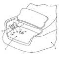
本発明実施例の物品収納構造10は、特に限定されるものではないが、図8、図9に示すように、車両VのラゲッジルームLの車両左右方向一側のラゲッジサイドに設けられる開口Loを通して物品20を収納する構造である。開口Loは、車体90をラゲッジルームL側から覆うラゲッジサイドトリム100に形成されている。なお、以下、ラゲッジルームL側から見たときを物品収納構造10の正面視(図中のA視)とし、特に説明する場合を除きこの正面視にて本発明実施例の物品収納構造10を説明する。An article storage structure according to an embodiment of the present invention will be described below with reference to the drawings.
The
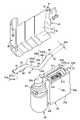
本発明実施例の物品収納構造10は、図2に示すように、物品20と、固定用部品30と、第1支持部材40と、第2支持部材50と、を有する。 The
物品20は、車に搭載される物品であり、パンク修理キットのコンプレッサである。ただし、物品20は、該コンプレッサに限定されるものではなく、エンジン始動時に用いられるバッテリ(補機バッテリ)であってもよく、車に搭載されるその他の物品であってもよい。
物品20は、固定用部品30、第1支持部材40および/または第2支持部材50に押されても変形しない程度の剛性を有している。物品20は、略直方体状であり、固定用部品30に対向する対向面である上面20aと、該上面20aと反対側の下面20bと、前面20cと、前面20cと反対側の後面20dと、右側面20eと、右側面20eと反対側の左側面20fと、を有している。物品20の左右方向長さ(右側面20eと左側面20fとの間隔)は、物品20の前後方向長さ(前面20cと後面20dとの間隔)よりも大となっている。 The
物品20の上面20aには、固定用部品30から離れる方向(下方)に凹む凹部21が設けられている。凹部21は、物品20の上面20aの略全域にわたって設けられている。凹部21の平面視における形状は、物品20の上面20aを一回り小さくした形状であり、左右方向長さ21aが前後方向長さ21bよりも大となっている矩形である。凹部21の底面21cは、平面となっている。 An
物品20の左側の側方、すなわち左側面20fに対向する位置には、パンクの補修材が入ったボトル容器25が物品20と独立して設けられている。ボトル容器25には、図示略のタイヤがパンクした際にタイヤに接続されるホース26が巻き付けられている。ボトル容器25の上下方向長さ(高さ)は、物品20の上下方向長さ(高さ)よりも大となっており、ボトル容器25の上端部25aは物品20の上面20aよりも固定用部品30側(上側)に位置している。 A
固定用部品30は、厚みが一定(略一定を含む)であり延び方向の全体にわたって幅が一定(略一定を含む)の帯状である。固定用部品30の幅30aは、物品20の凹部21の前後方向長さ21bと同じかもしくは公差分だけ狭くされている。固定用部品30は、物品20の上方に配置されており、物品20に上方から干渉することで物品20を固定する。固定用部品30は、複数部品構成であってもよいが、部品点数削減のために一部品構成であることが望ましい。 The fixing
固定用部品30は、高剛性材料で形成される剛体であってもよいが、弾性変形はするが塑性変形し難い材料で形成されていることが望ましい。すなわち、固定用部品30は、剛性が低く強度が高い材料で形成されることが望ましい。固定用部品30は、金属製であってもよく、樹脂製であってもよい。固定用部品30が金属製である場合、固定用部品30は、たとえば厚さが1mm未満の高強度鋼板(薄板材)で形成される。また、固定用部品30が樹脂製である場合、固定用部品30は、たとえば、CFRP(Carbon Fiber Reinforced Plastics),GFRP(Glass Fiber Reinforced Plastics)等で形成される。 The fixing
帯状の固定用部品30は、その延び方向で、一端部31と、他端部32と、湾曲部33と、一端部側連結部34と、他端部側連結部35と、を有する。 The strip-shaped
一端部31は、第1支持部材40に支持されている。一端部31には、ストッパ31aが設けられている。ストッパ31aは、一端部31の先端とその近傍を固定用部品30の幅方向と異なる方向に曲げ加工することで形成される抜け止め部31a1と、抜け止め部31a1から離間した位置に設けられており固定用部品30の幅方向に突出して設けられる突出部31a2と、を有する。抜け止め部31a1を第1支持部材40に設けられる貫通孔41に挿入し、第1支持部材40に対して抜け止め部31a1と突出部31a2を互いに反対側に位置させることで、一端部31は第1支持部材40に支持される。なお、固定用部品30の一端部31は、図7に示すように、第1支持部材40に固定されていてもよく、さらには、第1支持部材40と一体に形成されていてもよい。 One
図2に戻って、他端部32は、第2支持部材50に着脱可能に係合される。他端部32が第2支持部材50に設けられる貫通孔51に挿入されているとき、他端部32は第2支持部材50に係合された状態にあり、他端部32が第2支持部材50に設けられる貫通孔51から抜けた状態にあるとき、他端部32は第2支持部材50に係合されておらず第2支持部材50から離脱した状態にある。 Returning to FIG. 2 , the
他端部32は、一端部31が第1支持部材40に支持されている状態で、後述する弾性部60を弾性変形させて復元させることで、第2支持部材50の貫通孔51に挿入される(係合される)。 The
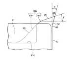
図3に示すように、湾曲部33は、一端部31と他端部32の間で物品20側(下方)に凸となるようにして設けられている。湾曲部33は、1つのみ設けられている。湾曲部33は、最下端部を含む極小部33aと、極小部33aの両側にあり極小部33aから離れる方向かつ上方に傾斜する一対の傾斜部33bと、を有する。そして、一対の傾斜部33bは、それぞれ、極小部33aに連なり直線状(略直線状を含む)に延びるストレート部33b1と、ストレート部33bに連なり湾曲して延びる移行部33b2と、を有する。 As shown in FIG. 3, the
湾曲部33は、固定用部品30の一端部31が第1支持部材40に支持された状態にあり固定用部品30の他端部32が第2支持部材50に係合されているとき、物品20と干渉して物品20を固定する。 When the one
湾曲部33は、一端部31が第1支持部材40に支持され他端部32が第2支持部材50に係合されているとき、物品20の凹部21に挿入されており極小部33aにて凹部21の底面21cに接触している。湾曲部33は、凹部21の底面21cに接触しているだけであってもよいが、弾性部60の弾性力(復元力)にて凹部21の底面21cに押し付けられており物品20から反力が付与されていることが望ましい。 When the one
一端部31が第1支持部材40に支持され他端部32が第2支持部材50に係合されているとき、湾曲部33の一対の傾斜部33bは、凹部21の左右の開口縁21dにそれぞれ当てられていてもよく、左右の開口縁21dとの間にそれぞれ最小隙のみ有していてもよい。 When the one
一端部側連結部34は、一端部31と湾曲部33とをつなぐ部分である。一端部側連結部34は、一端部31と湾曲部33との間で直線状(略直線状を含む)に延びている。一端部側連結部34は、一端部31と同じかまたは一端部31より物品20側(下側)の領域にあり、一端部31より上側の領域には存在しない。一端部側連結部34は、湾曲部33の一方の傾斜部33bに連なっている。 The one end
一端部側連結部34は、ボトル容器25の上方に位置しており、ボトル容器25に上方から干渉することでボトル容器25を固定していてもよい。なお、一端部側連結部34とボトル容器25とが干渉することで異音が生じる場合には、該異音を抑制するために、一端部連結部34とボトル容器25との間にクッション材80が設けられていてもよい。 The one-
他端部側連結部35は、他端部32と湾曲部33とをつなぐ部分である。他端部側連結部35は、他端部32と湾曲部33との間で直線状(略直線状を含む)に延びている。他端部側連結部35は、他端部32と同じかまたは他端部32より物品20側(下側)の領域にあり、他端部32より上側の領域には存在しない。他端部側連結部35は、湾曲部33の他方の傾斜部33bに連なっている。 The other end
図2に示すように、第1支持部材40は、物品20およびボトル容器25より左側で上下方向に延びて設けられている。第1支持部材40は物品20およびボトル容器25を左側から支持可能である。第1支持部材40は、上端部またはその近傍に、固定用物品30の一端部31が挿入される貫通孔41を有する。貫通孔41は、固定用部品30の横断面視形状より僅かに大きい形状とされている。 As shown in FIG. 2, the
第2支持部材50は、物品20より右側で上下方向に延びて設けられている。第2支持部材50は物品20およびボトル容器25を右側から支持可能である。第2支持部材50は、上端部またはその近傍に、固定用部品30の他端部32が挿入される貫通孔51を有する。貫通孔51は、固定用部品30の横断面視形状より僅かに大きい形状とされている。 The
第1支持部材40と第2支持部材50は、それぞれ別体に形成されていてもよいが、物品20を支持するトレイ70を介して一体に形成されていることが望ましい。すなわち、第1支持部材40と第2支持部材50は、トレイ70と共に一体に形成されていることが望ましい。なお、第1支持部材40と第2支持部材50とトレイ70が一体に形成されたものを、ハウジングといってもよい。 The
第1、第2支持部材40,50およびトレイ70は、弾性変形はするが塑性変形し難い材料で形成されていることが望ましい。すなわち、第1、第2支持部材40,50およびトレイ70は、剛性が低く強度が高い材料で形成されることが望ましい。第1、第2支持部材40,50およびトレイ70は、金属製であってもよく、樹脂製であってもよい。第1、第2支持部材40,50およびトレイ70が金属製である場合、第1、第2支持部材40,50およびトレイ70は、たとえば厚さが1mm未満の高強度鋼板(薄板材)で形成される。また、第1、第2支持部材40,50およびトレイ70が樹脂製である場合、第1、第2支持部材40,50およびトレイ70は、たとえば、CFRP(Carbon Fiber Reinforced Plastics),GFRP(Glass Fiber Reinforced Plastics)等で形成される。 The first and
トレイ70は、物品20およびボトル容器25が載せられる略平板状の床部71と、床部71から物品20およびボトル容器25の後側に立ち上がる略平板状の立壁部72と、を有する。立壁部72は、物品20およびボトル容器25を後側から支持可能である。 The
第1支持部材40は、トレイ70の立壁部72の左側端部から前方に延びて設けられている。第2支持部材50は、トレイ70の立壁部72の右側端部から前方に延びて設けられている。第1支持部材40と第2支持部材50は互いに対向する位置に設けられている。第1、第2支持部材40、50とトレイ70の床部71とは、上下方向に離れている。第1、第2支持部材40,50は、トレイ70が車体90に直接または図示略のブラケットを介して固定されることで、車体90に固定されている。 The
弾性部(弱体部といってもよい)60は、第2支持部材50に設けられる。ただし、弾性部60は、固定用部品30と第1支持部材40と第2支持部材50の少なくともいずれか1つに設けられていればよい。 An elastic portion (which may also be referred to as a weakened portion) 60 is provided on the
弾性部60は、第2支持部材50の上下方向中間部で第2支持部材50の前後方向の全域に設けられる。弾性部60は、自身が弾性変形する(撓む)ことで、弾性部60よりも上方に位置する第2支持部材50部分(以下、弾性部上部52という)を左右方向、すなわち第1支持部材40に接近離反する方向(図2の矢印F)に変位させる。弾性部上部52に貫通孔51が形成されている。弾性部60は、第2支持部材50の一部をその他の部分に比べて薄肉化させること、第2支持部材50の一部の前後方向長さをその他の部分に比べて短くさせること、第2支持部材50の一部に孔を設けること、等により作製される。 The
ここで、物品収納構造10における物品20の固定方法を説明する。
物品20の固定方法は、
(i)図4の(a)に示すように、第1、第2支持部材40,50(およびトレイ70)に、物品20とボトル容器25をセットする工程と、
(ii)図4の(b)に示すように、固定用部品30の一端部31を第1支持部材40の貫通孔41に差し込んで(挿入させて)引っ掛け、第1支持部材40にて一端部31を支持する工程と、
(iii)図4の(c)に示すように、固定用部品30を一端部31まわりに物品20側(下方)に回動させて、固定用部品30の湾曲部33を物品20の凹部21に合わせて挿入する(差し込む)工程と、
(iv)図4の(d)に示すように、固定用部品30の他端部32を物品20側(下方)に押し込み、弾性部60を弾性変形させて弾性部上部52を変位させることで他端部32を第2支持部材50の貫通孔51に差し込む(係合させる)工程と、
をこの順に有する。Here, a method for fixing the
The fixing method of the
(i) as shown in (a) of FIG. 4, a step of setting the
(ii) As shown in FIG. 4B, one
(iii) As shown in (c) of FIG. 4 , the fixing
(iv) As shown in (d) of FIG. 4, the
in this order.
上記(i)の工程について
(i-a)上記(i)の工程は、第1、第2支持部材40,50が予め車体90に固定された状態で行われる。
(i-b)物品20とボトル容器25は、それぞれ別々にセットされてもよいし、同時にセットされてもよい。
(i-c)物品20がバッテリなどからなり物品20の横にボトル容器25が設けられていない場合には、物品20のみがセットされボトル容器25はセットされない。
(i-d)上記(i)の工程は、物品20とボトル容器25をセットするだけであり、物品収納構造10のユーザは片手で行うことができる。Step (i) (ia) Step (i) is performed with the first and
(ib) The
(i-c) When the
(id) The above step (i) simply involves setting the
上記(ii)の工程について
(ii-a)一端部31が第1支持部材40に支持されているとき、ストッパ31aにて一端部31aが第1支持部材40の貫通孔41から抜けることが抑制され、これにより固定用部品30が第1支持部材40から脱落することが抑制される。
(ii-b)固定用部品30の一端部31が第1支持部材40に固定されている場合や第1支持部材40と一体に形成されている場合には、本工程は省略される。
(ii-c)上記(ii)の工程は、一端部31を第1支持部材40の貫通孔41に差し込むだけであり、物品収納構造10のユーザは片手で行うことができる。Regarding the above step (ii), (ii-a) when the one
(ii-b) If the one
(ii-c) The above step (ii) simply involves inserting the one
上記(iii)の工程について
(iii-a)凹部21には、固定用部品30の湾曲部33のみが挿入される。
(iii-b)上記(iii)の工程は、固定用部品30を一端部31まわりに回動させるだけであり、物品収納構造10のユーザは片手で行うことができる。Regarding the above step (iii), (iii-a) only the
(iii-b) The above step (iii) simply involves turning the fixing
上記(iv)について
(iv-a)固定用部品30の他端部32を押し込むことで、弾性部60を弾性変形させて第2支持部材50の弾性部上部52を第1支持部材40から離れる方向(右側)に変位させる。そして、他端部32が第2支持部材50の貫通孔51の位置に達したとき、弾性部60が復元し第2支持部材50の弾性部上部52が第1支持部材40に接近する方向(左側)に変位し、他端部32が貫通孔51に差し込まれる(係合される)。そして、弾性部60の復元力により、他端部32が貫通孔51から抜けることが抑制される。
(iv-b)図6に示すように、弾性部60は、撓みやすさ、固定用部品30の他端部32の貫通孔51への差し込みやすさ(引っ掛けやすさ、係合させやすさ)の観点から、上下方向(鉛直方向)から角度α(0<α<45°)だけ傾いていることが望ましい。また、固定用部品30の他端部32は、押し込み時の操作性(押しやすさ)や物品20の固定性の観点から、上下方向と直交する方向(水平方向)から角度β(0<β<45°)だけ傾いていることが望ましい。なお、図6では、固定用部品30の他端部32が第2支持部材50に係合されている状態を示しているが、上記の角度αと角度βは、固定用部品30の他端部32が第2支持部材50に係合されている状態だけでなく、固定用部品30の他端部32が第2支持部材50に係合される前の状態であっても成立していることが望ましい。
(iv-c)図3に示すように、固定用部品30の他端部32が第2支持部材50に係合されたとき、固定用部品30の湾曲部33は、物品20の凹部21の底面21cに接触している。さらには、弾性部60の復元力により、湾曲部33は、凹部21の底面21cに押し付けられている。
(iv-d)上記(iv)の工程は、固定用部品30の他端部32を物品20側(下方)に押し込むだけであり、物品収納構造10のユーザは片手で行うことができる。Regarding the above (iv), (iv-a) by pushing the
(iv-b) As shown in FIG. 6, the
(iv-c) As shown in FIG. 3, when the
(iv-d) The step (iv) is simply pushing the
上記(i)~(iv)の工程を経て固定された物品20の固定の解除は、つぎのようにして行われる。
図5に示すように、第2支持部材50の弾性部上部52を第1支持部材40から離れる方向(右側)E1に押す。これにより、第2支持部材50の弾性部上部52を弾性部60の弾性変形を伴って変位させ、固定用部品30の他端部32を第2支持部材50の貫通孔51から外す(抜く)。なお、固定用部品30の他端部32を貫通孔51から外す際に他端部32の先端を左方向E2に押して固定用部品30を撓ませることで、他端部32を貫通孔51から容易に外すことができる。The fixing of the
As shown in FIG. 5, the upper
この、第2支持部材50の弾性部上部52を第1支持部材40から離れる方向(右側)E1に押す作業をたとえば親指で行い、固定用部品30の他端部32の先端を左方向E2に押す作業をたとえば同じ手の人差し指等で行うことにより、物品収納構造10のユーザは片手で固定解除することができる。 This operation of pushing the elastic
つぎに、本発明実施例の作用、効果を説明する。 Next, the operation and effect of the embodiment of the present invention will be explained.
(A)図3に示すように、固定用部品30の一端部31が第1支持部材40に支持され他端部32が第2支持部材50に係合されているとき、固定用部品30には弾性部60の復元力D1がかかっている。そして、湾曲部33が物品20の凹部21の底面21cに押し付けられるため、固定用部品30には、物品20から上方への反力D2が生じる。反力D2によって固定用部品30は上に持ち上がろうとするが、一端部31が第1支持部材40に支持され他端部32が第2支持部材50に係合されており貫通孔41,51のそれぞれの上縁から下向きの力D3を受けるため、固定用部品30は持ち上がらない。固定用部品30が持ち上がらないため、反力D2によって固定用部品30に一端部31と他端部32が互いに離れる方向の力D4が働くが、この力D4も第1支持部材40と第2支持部材50によって押さえられる。結果として、物品20を固定用部品30を用いて第1、第2支持部材40,50に上下方向に固定することができる。(A) As shown in FIG. 3, when one
(B)本発明実施例では、弾性部60を弾性変形させて固定用部品30の他端部32を第2支持部材50に係合させるため、固定用部品30を第2支持部材50に係合させたときは、弾性部60の弾性力(復元力)により、固定用部品30を物品20に干渉(接触)させて物品20を固定することができる。この構造では、物品20を固定する際にナットを要しないため、ナットを締め付けるための工具が不要であり、物品20を固定する際の手間をナットを要する場合(従来)よりも省くことができる。(B) In the embodiment of the present invention, the
(C)弾性部60の弾性力によって固定用部品30の湾曲部33が物品20に押し付けられるため、固定用部品30は物品20を固定するとともに、押し付けている方向(上下方向)に物品が動くこと(がたつくこと)を抑制できる。(C) Since the
(D)固定用部品30の湾曲部33が物品20に押し付けられるため、湾曲部33が設けられておらず固定用部品30の略全体が物品20の一面全体に押し付けられる場合に比べて、固定用部品30と物品20との接触面積を小さくでき、固定用部品30から物品20へ局所的に押圧荷重をかけることができる。よって、固定用部品30から物品20への単位面積当たりの押圧力を高めることができ、固定用部品30による物品20の保持力を高めることができる。(D) Since the
(E)固定用部品30の一端部側連結部34と他端部側連結部35が、それぞれ、直線状に延びているため、固定用部品30の一端部31が第1支持部材40に支持され他端部32が第2支持部材50に係合され湾曲部33が物品20に押し付けられるとともに物品20から反力D2を受けているときに、一端部側連結部34および他端部側連結部35に主にかかる力を圧縮力とすることができる。よって、固定用部品30が物品20から反力D2を受けているときに一端部側連結部34および他端部側連結部35が曲げ変形してしまうことを抑制でき、湾曲部33を効率よく物品20に押し付けることができる。(E) Since the one end
(F)湾曲部33が物品20の凹部21に挿入されているため、凹部21の壁面が湾曲部33に当たる(接触する)までしか、物品20は固定用部品30に対して固定用部品30に押さえ付けられる方向以外の方向(前後方向、左右方向)へ移動できない。よって、物品20が固定用部品30に対して固定用部品30に押さえ付けられる方向以外の方向へ移動することを抑制できる。
具体的には、固定用部品30の幅30aが、物品20の凹部21の前後方向長さ21bと同じかもしくは公差分だけ狭くされているため、凹部21に湾曲部33を挿入するだけで、物品20が固定用部品30に対して前後方向に動くことを抑制できる。また、湾曲部33の一対の傾斜部33bが、凹部21の左右の開口縁21dにそれぞれ当てられるかまたは開口縁21dとの間に最小隙のみ有するため、凹部21に湾曲部33を挿入するだけで、物品20が固定用部品30に対して左右方向に動くことを抑制できる。(F) Since the
Specifically, since the
(G)上記(A)~(C)と上記(F)により、物品20を、固定用部品30を用いて上下方向、前後方向、左右方向の全方向で規制できる。よって、物品20を安定して固定できる。(G) According to (A) to (C) and (F) above, the
(H)第1支持部材40と第2支持部材50が一体に形成されているため、第1支持部材40と第2支持部材50がそれぞれ別体に形成される場合に比べて、部品点数を削減できコスト上有利である。(H) Since the
(I)第1支持部材40と第2支持部材50が車体90に固定されている。そして、固定用部品30の一端部31が第1支持部材40に支持され他端部32が第2支持部材50に係合されている。よって、第1支持部材40、第2支持部材50および固定用部品30によって物品20を車体90に固定できる。(I) The
(J)物品20の、第1、第2支持部材40,50への固定と固定解除を片手で行うことができるため、図9に示すように、ラゲッジサイドに設けられる開口Loから物品収納構造10の裏側(後側)に手を回り込ませるスペース(幅)Sが片手分しかない(たとえば80mm程度しかない)場合であっても、物品20の第1、第2支持部材40,50への固定と固定解除を行うことができる。(J) Since the
(K)固定用部品30、第1支持部材40および第2支持部材50が鋼板(鉄板)でも製作できるシンプルかつ安価な構造であるため、コスト低減を図る点で有利である。(K) Since the fixing
(L)第1支持部材40と第2支持部材50を有しており、第1支持部材40が物品20の左側にあり第2支持部材50が物品20の右側にあるため、ゴムバンド110を第1、第2支持部材50に容易に掛け渡すことができる。よって、ゴムバンド110にて物品20の固定力を高めることができる。(L) Since it has a
本発明実施例では、弾性部60が第2支持部材50の上下方向中間部のみに設けられる場合を説明したが、弾性部60は、第1支持部材50の上下方向中間部のみに設けられていてもよく、固定用部品30の延び方向中間部のみに設けられていてもよい。弾性部60は、第2支持部材50の上下方向中間部と第1支持部材40の上下方向中間部と固定用部品30の延び方向中間部の少なくとも一つに設けられていればよい。 In the embodiment of the present invention, the
10 物品収納構造
20 物品
21 凹部
21c 凹部の底面
21d 左右の開口縁
25 ボトル容器
30 固定用部品
31 一端部
31a ストッパ
32 他端部
33 湾曲部
33a 極小部
33b 傾斜部
33b1 ストレート部
33b2 移行部
34 一端部側連結部
35 他端部側連結部
40 第1支持部材
41 貫通孔
50 第2支持部材
51 貫通孔
52 弾性部上部
60 弾性部
70 トレイ
71 床部
72 立壁部
80 クッション材
90 車体
100 ラゲッジサイドトリム
L ラゲッジルーム
Lo 開口
V 車両10
Claims (4)
Translated fromJapanese前記物品と干渉することで該物品を固定する帯状の固定用部品と、
前記固定用部品の一端部を支持する第1支持部材と、
前記固定用部品の他端部が着脱可能に係合される第2支持部材と、
を有し、
前記第2支持部材は弾性変形可能な弾性部が設けられており、
前記固定用部品は、前記弾性部を弾性変形させて前記固定用部品の他端部を前記第2支持部材に係合させることで、前記物品と干渉して該物品を固定しており、
前記固定用部品は、前記一端部と前記他端部の間に前記物品側に凸となる湾曲部を有しており、前記固定用部品の他端部が前記第2支持部材に係合されているとき、前記弾性部の弾性力によって前記湾曲部が前記物品に押し付けられており、
前記物品は、前記固定用部品に対向する面に該固定用部品から離れる方向に凹む凹部を有しており、
前記固定用部品の他端部が前記第2支持部材に係合されているとき、前記湾曲部が前記凹部に挿入されており、
前記湾曲部は、前記固定用部品の他端部が前記第2支持部材に係合されているとき、前記弾性部の弾性力によって前記凹部の底面に押し付けられるとともに、物品収納構造の正面視における前記凹部の左右の開口縁の両方に接触している、物品収納構造。goods;
a strip-shaped fixing part that fixes the article by interfering with the article;
a first support member that supports one end of the fixing component;
a second support member to which the other end of the fixing component is detachably engaged;
has
The second support member is provided with an elastic portion that can be elastically deformed,
The fixing part interferes with the article and fixesthe article by elastically deforming the elastic portion to engage the other end of the fixing part with the second support member,
The fixing part has a curved portion projecting toward the article between the one end and the other end, and the other end of the fixing part is engaged with the second support member. when the curved portion is pressed against the article by the elastic force of the elastic portion;
The article has a concave portion recessed in a direction away from the fixing component on a surface facing the fixing component,
When the other end of the fixing component is engaged with the second support member, the curved portion is inserted into the recess,
When the other end of the fixing component is engaged with the second support member, the curved portion is pressed against the bottom surface of the recessed portion by the elastic force of the elastic portion, and is positioned at the bottom of the article storage structure when viewed from the front. An article storage structurein contact with both left and right opening edges of the recess .
前記一端部側連結部は、前記一端部と前記湾曲部の間で直線状に延びており、前記他端部側連結部は、前記他端部と前記湾曲部の間で直線状に延びている、請求項1記載の物品収納構造。The fixing component has a one-end-side connecting portion that connects the one-end portion and the curved portion, and a second-end-side connecting portion that connects the other end portion and the curved portion,
The one-end-side connecting portion extends linearly between the one-end portion and the curved portion, and the other-end-side connecting portion extends linearly between the other end portion and the curved portion. 2. An article storage structureaccording to claim 1, wherein:
前記第1支持部材と前記第2支持部材は、前記トレイとともに一体に形成されている、請求項1または請求項2記載の物品収納構造。having a tray for supporting the article;
3. The article storage structure according to claim1, wherein said first support member and said second support member are formed integrally with said tray .
Priority Applications (3)
| Application Number | Priority Date | Filing Date | Title |
|---|---|---|---|
| JP2019004416AJP7163783B2 (en) | 2019-01-15 | 2019-01-15 | Goods storage structure |
| US16/726,324US11292394B2 (en) | 2019-01-15 | 2019-12-24 | Article storage structure |
| CN202010018537.6ACN111434531B (en) | 2019-01-15 | 2020-01-08 | Article storage structure |
Applications Claiming Priority (1)
| Application Number | Priority Date | Filing Date | Title |
|---|---|---|---|
| JP2019004416AJP7163783B2 (en) | 2019-01-15 | 2019-01-15 | Goods storage structure |
Publications (2)
| Publication Number | Publication Date |
|---|---|
| JP2020111234A JP2020111234A (en) | 2020-07-27 |
| JP7163783B2true JP7163783B2 (en) | 2022-11-01 |
Family
ID=71517377
Family Applications (1)
| Application Number | Title | Priority Date | Filing Date |
|---|---|---|---|
| JP2019004416AActiveJP7163783B2 (en) | 2019-01-15 | 2019-01-15 | Goods storage structure |
Country Status (3)
| Country | Link |
|---|---|
| US (1) | US11292394B2 (en) |
| JP (1) | JP7163783B2 (en) |
| CN (1) | CN111434531B (en) |
Families Citing this family (1)
| Publication number | Priority date | Publication date | Assignee | Title |
|---|---|---|---|---|
| US11577655B2 (en)* | 2020-06-03 | 2023-02-14 | John J. Hahn | Flexible shelf guard for recreational vehicles |
Citations (2)
| Publication number | Priority date | Publication date | Assignee | Title |
|---|---|---|---|---|
| JP2009014107A (en) | 2007-07-04 | 2009-01-22 | Tokai Rubber Ind Ltd | Vibration damping device and its manufacturing method |
| JP2011031658A (en) | 2009-07-30 | 2011-02-17 | Toyoda Gosei Co Ltd | Cover device |
Family Cites Families (14)
| Publication number | Priority date | Publication date | Assignee | Title |
|---|---|---|---|---|
| JPS5066327U (en)* | 1973-10-20 | 1975-06-14 | ||
| JPS50111569U (en)* | 1974-02-21 | 1975-09-11 | ||
| GB1488723A (en)* | 1975-04-23 | 1977-10-12 | Mason R | Carrier for use in supporting a canoe or other elongate article on a vehicle roof |
| US20070154276A1 (en)* | 2006-01-04 | 2007-07-05 | Dollar Robert L Jr | Portable beverage cooler retention device for vehicles with tailgates |
| US20090001748A1 (en)* | 2007-06-29 | 2009-01-01 | Bbi Enterprises Group, Inc. | Trim Assembly For A Vehicle |
| JP2010285077A (en) | 2009-06-11 | 2010-12-24 | Toyota Motor Corp | Battery retention structure |
| DE102009033415B3 (en)* | 2009-07-16 | 2010-07-29 | Lisa Dräxlmaier GmbH | Adaptive storage |
| JP5645336B2 (en)* | 2009-10-13 | 2014-12-24 | 株式会社ニフコ | Object holding device |
| US8348332B2 (en)* | 2009-12-11 | 2013-01-08 | Honda Motor Co., Ltd. | Partition structure and installation structure for installation part |
| FR2963294B1 (en)* | 2010-07-30 | 2014-10-10 | Faurecia Automotive Ind | ACCESSORY HOLDING DEVICE WITH ADJUSTING MEANS, AND ASSOCIATED ASSEMBLY. |
| JP5585778B2 (en)* | 2011-02-01 | 2014-09-10 | スズキ株式会社 | Storage structure |
| US20120286009A1 (en)* | 2011-05-09 | 2012-11-15 | Blitz U.S.A., Inc. | Variable fuel container storage and transport carrier |
| NL1040133C2 (en)* | 2013-03-28 | 2014-09-30 | Cordstrap B V | Method and system for securing heavy loads. |
| US10227047B2 (en)* | 2017-03-07 | 2019-03-12 | David Purvis | Adjustable receptacle holder for a vehicle |
- 2019
- 2019-01-15JPJP2019004416Apatent/JP7163783B2/enactiveActive
- 2019-12-24USUS16/726,324patent/US11292394B2/enactiveActive
- 2020
- 2020-01-08CNCN202010018537.6Apatent/CN111434531B/enactiveActive
Patent Citations (2)
| Publication number | Priority date | Publication date | Assignee | Title |
|---|---|---|---|---|
| JP2009014107A (en) | 2007-07-04 | 2009-01-22 | Tokai Rubber Ind Ltd | Vibration damping device and its manufacturing method |
| JP2011031658A (en) | 2009-07-30 | 2011-02-17 | Toyoda Gosei Co Ltd | Cover device |
Also Published As
| Publication number | Publication date |
|---|---|
| CN111434531B (en) | 2023-05-23 |
| US20200223369A1 (en) | 2020-07-16 |
| JP2020111234A (en) | 2020-07-27 |
| US11292394B2 (en) | 2022-04-05 |
| CN111434531A (en) | 2020-07-21 |
Similar Documents
| Publication | Publication Date | Title |
|---|---|---|
| US9073498B2 (en) | Battery tray for vehicle | |
| US10322757B2 (en) | Lower vehicle structure | |
| US6945594B1 (en) | Vehicle load floor | |
| US11130526B2 (en) | Rear body structure for vehicles | |
| CN109927652B (en) | Storage battery bracket | |
| CN109204197B (en) | Battery support structure | |
| CN203580593U (en) | Storage battery mounting structure | |
| US7690464B2 (en) | Battery package mount bracket | |
| CN108068603B (en) | Vehicle lower structure | |
| JP7163783B2 (en) | Goods storage structure | |
| US20170368929A1 (en) | Hybrid vehicle including battery and fuel tank | |
| CN107054038A (en) | Vehicle | |
| US20140338492A1 (en) | Accelerator pedal device | |
| US8146976B2 (en) | Slide-out tray system for vehicles | |
| US20200001795A1 (en) | Vehicle storage system and vehicle including the vehicle storage system | |
| KR100926866B1 (en) | Undercover support structure | |
| KR20080026822A (en) | Driver's seat airbag module mounting structure | |
| CN214057247U (en) | Auxiliary instrument board subassembly and vehicle | |
| JP4894586B2 (en) | Priming pump mounting structure | |
| JP5824722B2 (en) | Car article storage case | |
| JP2600959Y2 (en) | Clip mounting seat for body interior parts | |
| KR102456787B1 (en) | Coupled structure od fastener holder and fastener | |
| JP4905102B2 (en) | Vehicle spare tire hanger | |
| JP2019034615A (en) | Automobile tool storage structure | |
| JP2023047020A (en) | vehicle |
Legal Events
| Date | Code | Title | Description |
|---|---|---|---|
| A621 | Written request for application examination | Free format text:JAPANESE INTERMEDIATE CODE: A621 Effective date:20210426 | |
| A977 | Report on retrieval | Free format text:JAPANESE INTERMEDIATE CODE: A971007 Effective date:20220421 | |
| A131 | Notification of reasons for refusal | Free format text:JAPANESE INTERMEDIATE CODE: A131 Effective date:20220426 | |
| A521 | Request for written amendment filed | Free format text:JAPANESE INTERMEDIATE CODE: A523 Effective date:20220620 | |
| A131 | Notification of reasons for refusal | Free format text:JAPANESE INTERMEDIATE CODE: A131 Effective date:20220705 | |
| A521 | Request for written amendment filed | Free format text:JAPANESE INTERMEDIATE CODE: A523 Effective date:20220829 | |
| TRDD | Decision of grant or rejection written | ||
| A01 | Written decision to grant a patent or to grant a registration (utility model) | Free format text:JAPANESE INTERMEDIATE CODE: A01 Effective date:20220920 | |
| A61 | First payment of annual fees (during grant procedure) | Free format text:JAPANESE INTERMEDIATE CODE: A61 Effective date:20221003 | |
| R151 | Written notification of patent or utility model registration | Ref document number:7163783 Country of ref document:JP Free format text:JAPANESE INTERMEDIATE CODE: R151 |