JP7162955B1 - Apparatus and method for preparing hydroxyapatite suspension - Google Patents
Apparatus and method for preparing hydroxyapatite suspensionDownload PDFInfo
- Publication number
- JP7162955B1 JP7162955B1JP2022554210AJP2022554210AJP7162955B1JP 7162955 B1JP7162955 B1JP 7162955B1JP 2022554210 AJP2022554210 AJP 2022554210AJP 2022554210 AJP2022554210 AJP 2022554210AJP 7162955 B1JP7162955 B1JP 7162955B1
- Authority
- JP
- Japan
- Prior art keywords
- container
- solution
- injection device
- phosphoric acid
- concentration
- Prior art date
- Legal status (The legal status is an assumption and is not a legal conclusion. Google has not performed a legal analysis and makes no representation as to the accuracy of the status listed.)
- Active
Links
Images


Classifications
- C—CHEMISTRY; METALLURGY
- C01—INORGANIC CHEMISTRY
- C01B—NON-METALLIC ELEMENTS; COMPOUNDS THEREOF; METALLOIDS OR COMPOUNDS THEREOF NOT COVERED BY SUBCLASS C01C
- C01B25/00—Phosphorus; Compounds thereof
- C01B25/16—Oxyacids of phosphorus; Salts thereof
- C01B25/26—Phosphates
- C01B25/32—Phosphates of magnesium, calcium, strontium, or barium
- C01B25/322—Preparation by neutralisation of orthophosphoric acid
- A—HUMAN NECESSITIES
- A61—MEDICAL OR VETERINARY SCIENCE; HYGIENE
- A61P—SPECIFIC THERAPEUTIC ACTIVITY OF CHEMICAL COMPOUNDS OR MEDICINAL PREPARATIONS
- A61P31/00—Antiinfectives, i.e. antibiotics, antiseptics, chemotherapeutics
- A61P31/10—Antimycotics
- C—CHEMISTRY; METALLURGY
- C01—INORGANIC CHEMISTRY
- C01B—NON-METALLIC ELEMENTS; COMPOUNDS THEREOF; METALLOIDS OR COMPOUNDS THEREOF NOT COVERED BY SUBCLASS C01C
- C01B25/00—Phosphorus; Compounds thereof
- C01B25/16—Oxyacids of phosphorus; Salts thereof
- C01B25/26—Phosphates
- C01B25/32—Phosphates of magnesium, calcium, strontium, or barium
Landscapes
- Chemical & Material Sciences (AREA)
- Organic Chemistry (AREA)
- Inorganic Chemistry (AREA)
- Health & Medical Sciences (AREA)
- Medicinal Chemistry (AREA)
- Life Sciences & Earth Sciences (AREA)
- Chemical Kinetics & Catalysis (AREA)
- General Chemical & Material Sciences (AREA)
- Communicable Diseases (AREA)
- Nuclear Medicine, Radiotherapy & Molecular Imaging (AREA)
- Pharmacology & Pharmacy (AREA)
- Oncology (AREA)
- Animal Behavior & Ethology (AREA)
- General Health & Medical Sciences (AREA)
- Public Health (AREA)
- Veterinary Medicine (AREA)
- Fertilizers (AREA)
- Control Of Non-Electrical Variables (AREA)
Abstract
Translated fromJapaneseDescription
Translated fromJapanese本発明は、ハイドロキシアパタイト懸濁液の作製装置及び方法に関する。 The present invention relates to an apparatus and method for producing a hydroxyapatite suspension.
ハイドロキシアパタイト(以下、HAと表記する)は、例えば、Ca10(PO4)6(OH)2で表される。HAの作製方法の一例として、溶液法がある。一般に、HAは乾燥した粉末状で運搬、販売、及び、利用される。HAは乾燥した場合に凝集する。凝集したHAの粒子サイズはマイクロサイズとなる。Hydroxyapatite (hereinafter referred to as HA) is represented by, for example,Ca10( PO4)6 (OH)2 . A solution method is one example of a method for producing HA. Generally, HA is transported, sold and used in dry powder form. HA aggregates when dried. The particle size of aggregated HA becomes micro size.
本発明の実施形態は、粒子サイズの小さいHAを含む懸濁液の作製装置及び方法を提供する。 Embodiments of the present invention provide apparatus and methods for making suspensions containing HA with small particle size.
本発明の実施形態に係るHA懸濁液の作製装置は、容器と、第1の注入装置と、第2の注入装置と、pH計と、制御装置と、注出装置と、温度計と、温度調節装置とを備える。第1の注入装置は、容器に水酸化カルシウムを注入する。第2の注入装置は、容器に収容されている溶液にリン酸を注入する。pH計は、容器内の溶液のpHを計測する。制御装置は、pH計によって計測されたpHが所定の範囲になるように、第1の注入装置によって注入される水酸化カルシウムの濃度と、第2の注入装置によって注入されるリン酸の濃度と注入速度とのうちの少なくとも一方とを制御する。注出装置は、容器内の溶液の自然沈降によって濃縮されたHA懸濁液を容器の外に注出する。温度計は、容器内の溶液の温度を計測する。温度調節装置は、容器内の溶液を加熱又は冷却する。制御装置は、自然沈降時に、温度計によって計測される温度が15℃以上25℃以下の範囲になるように温度調節装置を制御し、自然沈降の後に温度が2℃以上20℃以下の範囲になるように温度調節装置を制御する。
An HA suspension preparation apparatus according to an embodiment of the present invention includes a container, a first injection device, a second injection device, a pH meter, a control device, an extraction device, athermometer, and a temperature control device . A first injection device injects calcium hydroxide into the container. A second injection device injects phosphoric acid into the solution contained in the container. A pH meter measures the pH of the solution in the container. The controller adjusts the concentration of calcium hydroxide injected by the first injection device and the concentration of phosphoric acid injected by the second injection device so that the pH measured by the pH meter falls within a predetermined range. and at least one of the injection rate. The dispensing device dispenses the concentrated HA suspension out of the container by spontaneous sedimentation of the solution in the container.A thermometer measures the temperature of the solution in the container. A temperature control device heats or cools the solution in the container. The control device controls the temperature control device so that the temperature measured by the thermometer is in the range of 15 ° C. to 25 ° C. during natural settling, and the temperature is in the range of 2 ° C. to 20 ° C. after natural settling. Control the temperature control device so that
本発明の実施形態によれば、粒子サイズの小さいHAを含む懸濁液を作製することができる。 According to embodiments of the present invention, suspensions containing HA with small particle size can be made.
以下、本発明の実施形態を、図面を参照して説明する。なお、以下の説明において、略又は実質的に同一の機能及び構成要素については、同一符号を付し、説明を省略するか、又は、必要な場合にのみ説明を行う。 BEST MODE FOR CARRYING OUT THE INVENTION Hereinafter, embodiments of the present invention will be described with reference to the drawings. In the following description, substantially or substantially the same functions and components are denoted by the same reference numerals, and descriptions thereof are omitted or described only when necessary.
(第1の実施形態)
第1の実施形態においては、溶液法を用いて、粒子サイズの小さいHAを含み、運搬効率が高く、菌数の制御効果の大きいHA懸濁液の作製装置及び方法を説明する。(First embodiment)
In the first embodiment, an apparatus and a method for producing an HA suspension containing HA with a small particle size, high transport efficiency, and a large bacterial count control effect using a solution method will be described.
第1の実施形態によって作製されたHA懸濁液に含まれているHAは、ナノサイズを維持することができる。 The HA contained in the HA suspension made according to the first embodiment can maintain nano-size.
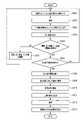
図1は、第1の実施形態に係る作製装置1の構成の一例を示すブロック図である。 FIG. 1 is a block diagram showing an example of the configuration of a
作製装置1は、制御装置2、第1の容器3、第1の注入装置4、第2の注入装置5、pH(水素イオン濃度指数)計6、温度計7、温度調節装置8、攪拌機37、第1の注出装置9、第の注出装置10を備える。作製装置1によって作製及び濃縮されたHA懸濁液11は、第2の容器12に収容される。 The
なお、作製装置1を構成する各種の装置は、適宜組み合わせてもよい。例えば、pH計6と温度計7とは1つの装置でもよい。例えば、第1の注出装置9と第2の注出装置10とは1台のポンプでもよい。 It should be noted that various devices constituting the
また、作製装置1を構成する各種の装置は、適宜分離してもよい。例えば、第1の容器3は、水酸化カルシウムにリン酸を滴下するために使用される容器と、水酸化カルシウムとリン酸とを混合した溶液13の自然沈降を行う容器とに分割してもよい。 Moreover, various devices constituting the
制御装置2は、pH計6によって計測されたpHを示す信号を受信し、温度計7によって測定された温度を示す信号を受信する。 The
制御装置2は、pH計6から受信した信号の示すpH及び温度計7から受信した信号の示す温度に基づいて、第1の注入装置4によって第1の容器3に注入される水酸化カルシウムの濃度、第2の注入装置5によって第1の容器3に注入(例えば滴下)されるリン酸の濃度と注入速度(例えば滴下速度)とのうちの少なくとも一方、溶液13のpH(合成pH)、HA合成時及び自然沈降時の溶液13の温度調節装置8による温度管理を制御する。 Based on the pH indicated by the signal received from the pH meter 6 and the temperature indicated by the signal received from the
制御装置2は、リン酸滴下後にさらにリン酸を追加滴下し、溶液13のpHを下げることで、カルシウム欠損型HA、又は、抗菌性重金属を含むカルシウム欠損型HAを意図的に作製する制御を実行してもよい。 The
第1の実施形態において、制御装置2は、水酸化カルシウムの濃度が第1の範囲内となるように、水酸化カルシウムの濃度を制御する。第1の範囲は、例えば0.01%以上50%以下などでもよい。 In the first embodiment, the
制御装置2は、リン酸の濃度が第2の範囲内となるように、リン酸の濃度を制御する。第2の範囲は、例えば0.01%以上50%以下などでもよい。 The
制御装置2は、HAの生産量に対するリン酸の注入速度が第3の範囲内となるように、リン酸の注入速度を制御する。第3の範囲は、例えば0.01ml/min/g以上100ml/min/g以下などでもよい。第3の範囲は、好ましくは0.1ml/min/g以上10ml/min/g以下などでもよい。 The
制御装置2は、第1の容器3内の溶液13のpHが第4の範囲内となるように、水酸化カルシウムとリン酸とのうちの少なくとも一方の注入量を制御する。第4の範囲は、例えば5以上13以下などでもよい。 The
制御装置2は、水酸化カルシウムとリン酸とを混合してHA懸濁液を合成する合成温度、及び、水酸化カルシウムとリン酸とが反応中の温度が第5の範囲内となるように、溶液13の温度を制御する。第5の範囲は、例えば5℃以上50℃以下などでもよい。第5の範囲は、好ましくは例えば5℃以上30℃以下などでもよい。HA作製反応中は反応熱により溶液13の温度が上昇する傾向にあるが、制御装置2及び温度調節装置8の動作によりHA作製に適した状態を実現することができる。 The
制御装置2は、例えば、記憶装置2a及びプロセッサ2bを備えるとしてもよい。この場合、記憶装置2aはソフトウェア2cを記憶する。記憶装置2aは、非一時的な記憶装置と、キャッシュメモリなどの一時的な記憶装置とを含むとしてもよい。ソフトウェア2cは、プログラムとデータとを含むとしてもよい。プロセッサ2bは、記憶装置2aに記憶されているソフトウェア2cを実行し、HA懸濁液11を作製するための各種の制御を実行する。 The
制御装置2は、水酸化カルシウムとリン酸との混合(HA合成)時に、撹拌機37に、容器3内の溶液13を攪拌させるための制御を実行する。より具体的には、制御装置2は、第2の注入装置5によるリン酸の滴下処理時に、攪拌機37に対して回転数の示す信号を送信する。例えば、制御装置2は、攪拌機37を例えば50rpm以上1000rpm以下で回転させるための信号を、攪拌機37に送信する。より好ましくは、制御装置2は、攪拌機37を例えば100rpm以上500rpm以下で回転させるための信号を、攪拌機37に送信する。 The
制御装置2は、第1の容器3から溶液13の上澄み部分を注出した後であり第1の容器3から濃縮されたHA懸濁液11を注出する前に、攪拌機37に、第1の容器3内の濃縮されたHA懸濁液11を攪拌させるための制御を実行する。より具体的には、制御装置2は、濃縮されたHA懸濁液11の注出前に、攪拌機37に対して回転数の示す指示を送信する。例えば、制御装置2は、攪拌機37を例えば50rpm以上1000rpm以下で回転させるための信号を、攪拌機37に送信する。より好ましくは、制御装置2は、攪拌機37を例えば100rpm以上500rpm以下で回転させるための信号を、攪拌機37に送信する。この撹拌機37による攪拌により、濃縮されたHA懸濁液11の濃度を均一化することができる。 After pouring the supernatant portion of the
制御装置2は、第1の注出装置9に対して、第1の容器3内に収容されている溶液13のうちの上澄み部分の注出を指示する。 The
制御装置2は、第2の注出装置10に対して、第1の容器3内に収容されている溶液13のうちの沈降部分(すなわち濃縮されたHA懸濁液11)の注出を指示する。 The
第1の容器3は、第1の注入装置4から注入された水酸化カルシウム(液)を収容する。 The
第1の容器3は、第2の注入装置4によって注入(例えば滴下)されるリン酸(液)を受ける。 The
第1の容器3内で、水酸化カルシウムとリン酸とが反応し、HAを含む溶液13が作製(合成)される。 Calcium hydroxide and phosphoric acid react in the
第1の注入装置4は、制御装置2から水酸化カルシウムの濃度を示す信号を受信する。第1の注入装置4は、受信した信号に基づいて、水酸化カルシウムの濃度を調節し、濃度が調節された水酸化カルシウムを第1の容器3に注入する。第1の実施形態において、水酸化カルシウムの純度は、90%以上100%以下としてもよい。 The
第1の注入装置4は、水酸化カルシウムと抗菌性重金属を含む化合物との混合液を、第1の容器3に注入してもよい。第1の実施形態において、抗菌性重金属は、例えば、銀、銅、パラジウム、白金、カドミウム、ニッケル、コバルト、亜鉛、マンガン、タリウム、鉛、又は、水銀としてもよい。 The
第2の注入装置5は、制御装置2からリン酸の濃度を示す信号及びリン酸の注入速度を示す信号を受信する。第2の注入装置5は、受信した信号の示す濃度のリン酸を、受信した信号の示す注入速度で、第1の容器3にためられており水酸化カルシウムを含む溶液13に滴下する。 The
第2の注入装置4は、リン酸と抗菌性重金属を含む化合物との混合液を、第1の容器3内の溶液13に滴下してもよい。 The
pH計6は、第1の容器3内にためられている溶液13のpHを計測し、pHを示す信号を制御装置2に送信する。 The pH meter 6 measures the pH of the
温度計7は、第1の容器3内にためられている溶液13の温度を計測し、温度を示す信号を制御装置2に送信する。 A
温度調節装置8は、制御装置2から温度を示す信号を受信する。温度調節装置8は、水酸化カルシウムとリン酸との混合中(HA合成中)、及び、溶液13に対する自然沈降の実行中に、第1の容器3内の溶液13が受信した信号の示す温度となるように、第1の容器3内の溶液13の温度管理(例えば加熱又は冷却)を実行する。
撹拌機37は、制御装置2から回転数を示す信号を受信する。撹拌機37は、受信した信号の示す回転数にそって容器3内の溶液13を攪拌する。撹拌機37は、リン酸の滴下時(HA合成時)に溶液13を攪拌する。また、攪拌機37は、濃縮されたHA懸濁液11の注出前に濃縮されたHA懸濁液11を攪拌する。上澄み部分を注出した後の沈降部分には濃度勾配がある。第1の実施形態では、沈降部分を攪拌することにより沈降部分の濃度を均一化することができる。 The
第1の注出装置9は、制御装置2から注出指示を示す信号を受信する。第1の注出装置9は、受信した信号に基づいて、第1の容器3から溶液13の上澄み部分を注出し、溶液13の沈降部分(すなわち濃縮されたHA懸濁液11)を第1の容器3内に残す。 The first pouring device 9 receives a signal indicating a pouring instruction from the
第1の注出装置9の吸水口は、上澄み部分と沈降部分との境界位置に応じて上下に移動可能である。より具体的には、第1の注出装置9の吸水口の高さは、上澄み部分と沈降部分との境界位置の上になるように調節される。これにより、効率的に上澄み部分を注出して第1の容器3に沈降部分を残すことができる。 The water intake of the first pouring device 9 can move up and down according to the boundary position between the supernatant portion and the sedimentation portion. More specifically, the height of the water intake of the first pouring device 9 is adjusted to be above the boundary position between the supernatant portion and the sedimentation portion. Thereby, it is possible to efficiently pour out the supernatant portion and leave the settled portion in the
第2の注出装置10は、制御装置2から注出指示を示す信号を受信する。第2の注出装置10は、受信した信号に基づいて、第1の容器3における溶液13の沈降部分を濃縮されたHA懸濁液として運搬用の第2の容器12に注入する。 The second pouring
図2は、第1の実施形態に係る作製装置1による水酸化カルシウムとリン酸との混合状態(HA合成状態)の一例を示す概念図である。この図2において、作製装置1のうちの第1の注出装置9及び第2の注出装置10は省略されている。 FIG. 2 is a conceptual diagram showing an example of a mixed state (HA synthesized state) of calcium hydroxide and phosphoric acid by the
第3の容器4aは、水酸化カルシウムの溶液を収容している。第1の注入装置4は、制御装置2から受信した信号の示す濃度に水酸化カルシウムを調節し、濃度の調節された水酸化カルシウムを第1の容器3に注入する。 A
第4の容器5aは、リン酸の溶液を収容している。第2の注入装置5は、制御装置2から受信した信号の示す濃度にリン酸を調節し、制御装置2から受信した信号の示す滴下速度で、濃度の調節されたリン酸を第1の容器3に滴下する。 A
制御装置2は、pH計6から溶液13のpHを示す信号を受信し、溶液13のpHに基づいて、第1の注入装置4及び第2の注入装置5の動作、及び、攪拌機37の攪拌処理を制御する。 The
制御装置2は、温度計7から溶液13の温度を示す信号を受信し、溶液13の温度に基づいて、温度調節装置8の動作を制御する。 The
第1の実施形態において、第1の注入装置4及び第2の注入装置5は、例えば、チューブポンプとしてもよい。 In the first embodiment, the
図3は、第1の実施形態に係る作製装置1によって実行されるHA懸濁液11の作製方法の一例を示すフローチャートである。図3の作製方法は、制御装置2による制御にそって実行される。 FIG. 3 is a flow chart showing an example of a method for producing the
S301において、第1の注入装置4は、制御装置2によって指定された濃度の水酸化カルシウムを第1の容器3に注入する。 At S<b>301 , the
S302において、攪拌機37は、制御装置2によって指定された回転数で動作し、第1の容器3内の溶液13を攪拌する。 In S<b>302 , the
S303において、第2の注入装置5は、制御装置2によって指定された濃度及び注入速度で、第1の容器3内の溶液13(水酸化カルシウム)に対してリン酸を滴下する。 In S<b>303 , the
S304において、pH計6は第1の容器3内の溶液13のpHを計測してpHを示す信号を制御装置2に送信し、温度計7は第1の容器3内の溶液13の温度を計測して温度を示す信号を制御装置2に送信する。 In S304, the pH meter 6 measures the pH of the
S305において、制御装置2は、水酸化カルシウムの濃度、リン酸の濃度及び注入速度、第1の容器3内の溶液13のpH、溶液13の温度の関係が適切か否かを判断する。この適切な各種材料の濃度、注入速度、pH、温度の関係は後で説明する。 In S305, the
制御装置2が濃度、注入速度、pH、温度の関係が適切ではないと判断した場合、S306において、制御装置2は、新規の水酸化カルシウムの濃度、新規のリン酸の濃度及び新規のリン酸の注入速度、新規のpH、第1の容器3内の溶液13の新規の温度を決定する。そして、制御装置2は、新規の水酸化カルシウムの濃度を示す信号を第1の注入装置4に送信する。第1の注入装置4は、制御装置2から受信した信号に基づいて、水酸化カルシウムの濃度を調節する。制御装置2は、新規のリン酸の濃度を示す信号及び新規のリン酸の注入速度を示す信号を第2の注入装置5に送信する。第2の注入装置5は、制御装置2から受信した信号に基づいて、リン酸の濃度及び注入速度を調節する。制御装置2は、新規の温度を示す信号を温度調節装置8に送信する。温度調節装置8は、制御装置2から受信した信号に基づいて、溶液13の温度を調節する。その後処理は、S301に戻る。 If the
なお、第1の実施形態の上記S306において、制御装置2は、新規の水酸化カルシウムの濃度の決定をしなくてもよく、新規の水酸化カルシウムの濃度を示す信号を第1の注入装置4に送信しなくてもよい。この場合、処理は、S302に戻る。 In the above S306 of the first embodiment, the
上記S305において制御装置2が濃度、注入速度、pH、温度の関係が適切であると判断した場合、S307において、制御装置2は、水酸化カルシウムにリン酸を滴下する動作の終了条件(滴下終了条件)が満たされるか否かを判断する。 If the
滴下終了条件は、例えば、第1の容器3内の溶液13のpHが目標範囲(目標pH)に到達していることとしてもよい。 The dropping end condition may be, for example, that the pH of the
溶液13のpHが目標pHに到達した後にしばらくすると溶液13のpHが上昇することがある。このため、制御装置2は、溶液13のpHが目標pHに到達した後であっても、その後再び第2の注入装置5に適宜リン酸の滴下を実行させ、溶液13のpHが安定した場合に、滴下終了条件を満たすと判断してもよい。 After a while after the pH of the
滴下終了条件は、例えば、第1の容器3内の溶液13の量が閾値を超えることなどとしてもよい。 The dropping end condition may be, for example, that the amount of the
制御装置2は、リン酸滴下後にさらにリン酸を追加滴下し、溶液13のpHを下げることで、カルシウム欠損型HA、又は、抗菌性重金属を含むカルシウム欠損型HAを意図的に作製してもよい。 The
制御装置2が終了条件を満たさないと判断した場合、処理はS301に戻る。なお、第1の実施形態のS306において、制御装置2が新規の水酸化カルシウムの濃度の決定をしない場合、処理はS302に戻るとしてもよい。 If the
制御装置2が終了条件を満たすと判断した場合、S308において、制御装置2は、第1の注入装置4、第2の注入装置5、攪拌機37に停止信号を送信する。第1の注入装置4、第2の注入装置5は、制御装置2から受信した信号にそって注入動作を停止する。攪拌機37は、制御装置2から受信した信号にそって攪拌動作を停止する。 When the
S309において、制御装置2は、自然沈降に適した温度を示す信号を温度調節装置8に送信する。温度調節装置8は、制御装置2から受信した信号に基づいて、溶液13の温度を調節する。 In S309, the
ステップS310において、所定時間以上、第1の容器3内の溶液13の自然沈降が実施される。 In step S310, natural sedimentation of the
S311において、第1の注出装置9は、制御装置2による制御にしたがって第1の容器3内の溶液13のうちの上澄み部分を注出して沈降部分を第1の容器3内に残す。 At S<b>311 , the first pouring device 9 pours out the supernatant portion of the
S312において、攪拌装置37は、制御装置2による制御にしたがって第1の容器3内の沈降部分である濃縮されたHA懸濁液11を攪拌する。 At S<b>312 , the stirring
S313において、第2の注出装置10は、制御装置2による制御にしたがって第1の容器3内の濃縮されたHA懸濁液11を注出し、第2の容器12に収容する。 At S<b>313 , the second pouring
図4は、第1の実施形態に係るHA懸濁液11の作製方法における自然沈降の例を示す概念図である。 FIG. 4 is a conceptual diagram showing an example of natural sedimentation in the method for producing the
第1の容器3内で作製されたHAを含む溶液13に対して所定時間の自然沈降を行う。自然沈降をする所定時間は、実験の結果、例えば1日以上60日以下でもよく、より好ましくは9日以上28日以下としてもよい。 The HA-containing
溶液13内のナノサイズのHAはゆっくり沈降する。溶液13の上澄み部分を除去すると、溶液13の沈降部分である濃縮されたHA懸濁液11が残る。このHA懸濁液11に含まれるHAはナノサイズを維持する。 The nano-sized HA in
濃縮されたHA懸濁液11を歯磨剤に混ぜることで、ナノサイズのHAが拡散した歯磨剤を作製することができる。 By mixing the
以下で、第1の実施形態における水酸化カルシウムの濃度、リン酸の注入速度、溶液13の温度の関係を説明する。 The relationship between the concentration of calcium hydroxide, the injection rate of phosphoric acid, and the temperature of the
HAの作製方法の1つである溶液法は、水熱合成及び乾式合成と比較して、HAの粒子サイズを小さくでき、大量生産に適した手法である。 The solution method, which is one method for producing HA, can reduce the particle size of HA compared to hydrothermal synthesis and dry synthesis, and is suitable for mass production.
溶液法には、硝酸カルシウムにリン酸アンモニウムを加えて合成を行うアンモニア系の溶液法と、水酸化カルシウムにリン酸を加える水酸化カルシウム系の溶液法がある。アンモニア系の溶液法では、アンモニアを使用するため洗浄が必要である。この洗浄のため、アンモニア系の溶液法ではHAの収量にロスが生じる。水酸化カルシウム系の溶液法では、副生成物がないため洗浄が不要である。このため、水酸化カルシウム系の溶液法は、アンモニア系の溶液法よりもHA収量率を高くすることができる。 The solution method includes an ammonia-based solution method in which ammonium phosphate is added to calcium nitrate and a calcium hydroxide-based solution method in which phosphoric acid is added to calcium hydroxide. Ammonia-based solution methods require cleaning due to the use of ammonia. This washing results in a loss of HA yield in the ammonia-based solution method. The calcium hydroxide-based solution method does not require washing because there are no by-products. Therefore, the calcium hydroxide-based solution method can provide a higher HA yield than the ammonia-based solution method.
ここでHA収量率とは、原料から算出される計算上のHA合成量に対する実際のHA生産量の率である。 Here, the HA yield rate is the ratio of the actual HA production amount to the calculated HA synthesis amount calculated from the raw materials.
HAを乾燥した粉末状で販売・利用する場合、ナノサイズのHAを作製しても乾燥により凝集し、HAがマイクロサイズになる場合がある。 When HA is sold and used in the form of dried powder, even if nano-sized HA is produced, it may be agglomerated by drying and become micro-sized.
そこで、第1の実施形態では、水酸化カルシウム系の溶液法を用いて、粒子サイズが小さく、かつ、運搬の効率及び菌数制御に優れた濃縮されたHA懸濁液11を作製する。以下では、第1の実施形態に係るHA懸濁液11の作製装置1及び方法で適用される諸条件(原料濃度、注入速度、温度、pHの影響等)を説明する。 Therefore, in the first embodiment, a
第1の実施形態では、第1の容器3内の溶液13のpHを調節することにより菌数制御を実現する。 In the first embodiment, bacterial count control is achieved by adjusting the pH of the
第1の実施形態では、遠心分離機及び乾燥を使用せず、自然沈降を用いて溶液13を濃縮することにより、HAの粒子サイズを小さいまま維持し、かつ、運搬効率を高める。 In a first embodiment, gravity sedimentation is used to concentrate the
さらに、第1の実施形態においては、好ましい自然沈降の温度と濃縮のための期間を説明する。 Furthermore, in the first embodiment, the preferred temperature for natural sedimentation and the period for concentration are described.
第1の実施形態においては、懸濁液を乾燥又は加熱し、生成物を分析及び同定する実験を行った。この実験により得られる生成物からリン酸三カルシウム(TCP)又は酸化カルシウム(CaO)が検出された。生成物がリン酸三カルシウムを含むのは、懸濁液中にCa欠損型HAが存在するためと考えられる。生産物が酸化カルシウムを含むのは、懸濁液中に水酸化カルシウムが存在するためと考えられる。HAの作製量を最大にするためには、懸濁液を適切なpHに制御することが重要である。 In a first embodiment, experiments were conducted to dry or heat the suspension and analyze and identify the products. Tricalcium phosphate (TCP) or calcium oxide (CaO) was detected in the product from this experiment. It is believed that the product contains tricalcium phosphate due to the presence of Ca-deficient HA in the suspension. It is believed that the product contains calcium oxide due to the presence of calcium hydroxide in the suspension. In order to maximize the amount of HA produced, it is important to control the suspension at the proper pH.
また、生成物のpHは温度により変動する。温度が低下すると、最適条件となるpHも低下する。 Also, the pH of the product varies with temperature. As the temperature decreases, the optimal pH also decreases.
表1は、温度とpHとHAの収量率との関係の実験結果の例を示す。
表1から、HA収量率が大きくなるpHは温度によって変動していることが分かる。表1において、温度25.5℃では、HA収量率が大きくなる適切なpHが8.5~9.0である。これに対して、温度19.1℃では、HA収量率が大きくなる適切なpHが9.5に上昇している。 From Table 1, it can be seen that the pH at which the HA yield increases varies with temperature. In Table 1, at a temperature of 25.5° C., the appropriate pH at which the HA yield increases is 8.5 to 9.0. In contrast, at a temperature of 19.1° C., the appropriate pH at which the HA yield increases increases to 9.5.
表2は、pHと水酸化カルシウムの濃度との関係の実験結果の例を示す。
水酸化カルシウムの濃度が96%~97%から超高濃度の99.9%に上がった場合、HA収量率が大きくなる適切なpHは1.5程度低下する。 When the concentration of calcium hydroxide is increased from 96%-97% to the ultra-high concentration of 99.9%, the appropriate pH for high HA yield drops by about 1.5.
表3は、合成時のリン酸の注入速度とHAの粒子サイズとの関係の実験結果の例を示す。この表3は、HAの収量が50gの時のリン酸の注入速度とHAの粒子サイズとの関係を示している。
合成時のリン酸の注入速度の上昇とともにHAの粒子サイズは大きくなる。 The particle size of HA increases with increasing injection rate of phosphoric acid during synthesis.
表4は、HAの収量とリン酸の注入速度とHAの粒子サイズとの関係の実験結果の例を示す。
この表4から、同じ粒径の場合に、HAの収量の増加とともにリン酸の注入速度を速くすることができることが分かる。例えば、HAの収量を2倍にすれば、リン酸の注入速度も2倍にすることができる。 From Table 4, it can be seen that for the same particle size, the injection rate of phosphoric acid can be increased as the yield of HA increases. For example, if the HA yield is doubled, the phosphoric acid injection rate can also be doubled.
表5は、水酸化カルシウムとリン酸とHAの粒径との関係の実験結果の第1の例を示す。この表5では、リン酸の濃度を一定としている。
表5から、水酸化カルシウムの濃度を高くするほどHAの粒径を小さくすることができる。 From Table 5, the particle size of HA can be made smaller as the concentration of calcium hydroxide is increased.
表6は、水酸化カルシウムとリン酸とHAの粒径との関係の実験結果の第2の例を示す。この表6では、水酸化カルシウムの濃度を一定としている。
表6から、リン酸の濃度を高くするほどHAの粒径を小さくすることができることが分かる。 From Table 6, it can be seen that the particle size of HA can be reduced as the concentration of phosphoric acid increases.
表7は、水酸化カルシウムの濃度とリン酸の濃度とHAの粒径との関係の実験結果の第3の例を示す。
表7から、水酸化カルシウムの濃度とリン酸の濃度を高くするほどHAの粒径を小さくすることができることが分かる。 From Table 7, it can be seen that the particle size of HA can be made smaller as the concentrations of calcium hydroxide and phosphoric acid are increased.
上記の表3乃至表7から、制御装置2は、例えば、水酸カルシウムの濃度を第1の閾値より高くし、リン酸の濃度を第2の閾値より高くし、リン酸の注入速度を第3の閾値より遅くなるように制御を実行する。第1の閾値は、例えば0.01%以上50%以下の範囲内のいずれかの値としてもよい。第2の閾値は、例えば0.01%以上50%以下の範囲内のいずれかの値としてもよい。第3の閾値は、HA作製量に対する注入速度に関する値であり、例えば0.01ml/min/g以上10ml/min/g以下の範囲内のいずれかの値としてもよい。 From Tables 3 to 7 above, the
これにより、溶液13及びHA懸濁液11に含まれるHAの粒子サイズを例えばナノサイズのように小さくすることができる。 As a result, the particle size of HA contained in the
第1の実施形態においては、第1の容器3内で作製された溶液13が乾燥されることなく自然沈降を用いて濃縮され、濃縮されたHA懸濁液11が第2の容器12に収容され、その後搬送及び利用される。 In the first embodiment, the
第1の実施形態においては、HAが懸濁液の状態で搬送及び利用される。このため、HAの粒子が凝集することを抑制し、粒子サイズが小さいままHAを利用することができる。粒子サイズの小さいHAは、付着対象との間で密着性に優れる。粒子サイズの小さいHAは、付着対象の表面積が減少することを防ぐことができる。 In a first embodiment, HA is delivered and utilized in suspension. Therefore, aggregation of HA particles can be suppressed, and HA can be used while the particle size is small. HA with a small particle size has excellent adhesion to the object to be adhered. HA with a small particle size can prevent the surface area to be attached from being reduced.
第1の実施形態においては、自然沈降により濃縮されたHA懸濁液11を作製することができるため、運搬効率を向上させることができる。 In the first embodiment, the
以下で、第1の容器3内の溶液13のpHと抗菌効果との関係を説明する。 The relationship between the pH of the
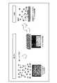
図5は、一般生菌検査の実験結果の例を示す図である。図5において、培地は標準観点培地である。サンプルのpHは、6.0、10.0、10.5である。第1の容器3内の溶液13(原液)の0.1gを寒天培地に滴下した。培養は35℃で48時間行った。図5では、各サンプルについて1グラム当たりの菌のコロニーの数が表記されている。 FIG. 5 is a diagram showing an example of experimental results of a general viable bacteria test. In FIG. 5, the medium is standard perspective medium. The pH of the samples is 6.0, 10.0, 10.5. 0.1 g of the solution 13 (stock solution) in the
図6は、真菌検査の実験結果の例を示す図である。図6において、培地はポテトデオキシロース寒天培地にクロラムフェニコールを添加したものである。サンプルのpHは、6.0、10.0、10.5である。第1の容器3内の溶液13(原液)の0.1gを寒天培地に滴下した。培養は25℃で5日間行った。図6では、各サンプルについて1グラム当たりの菌のコロニーの数が表記されている。 FIG. 6 is a diagram showing an example of experimental results of fungal examination. In FIG. 6, the medium is a potato deoxyrose agar medium supplemented with chloramphenicol. The pH of the samples is 6.0, 10.0, 10.5. 0.1 g of the solution 13 (stock solution) in the
図5及び図6のいずれにおいても、pH10以下では殺菌効果はなく、pH10.5以上で殺菌効果が得られる。 5 and 6, there is no bactericidal effect at a pH of 10 or less, and a bactericidal effect is obtained at a pH of 10.5 or more.
一般生菌検査におけるアルカリ領域での生育限界はpH8からpH9となる。真菌検査におけるアルカリ領域での生育限界はpH8.5となる。溶液13においては、pHが10では十分な菌数制御の結果が得られない。しかしながら、溶液13においては、pHが10.5以上で菌数制御の効果が得られる。pHが10.5以上の溶液13には、わずかな未反応の水酸化カルシウムが含まれている。この未反応の水酸化カルシウムが懸濁液のpHを高い値にしており、菌の繁殖を抑制している。このように、溶液13のpHを制御することにより、菌数を抑制することができる。 The limit of growth in the alkaline region in general viable bacteria inspection is from
図7は、オートクレーブ殺菌の実験結果の例を示す図である。図7において、オートクレーブ殺菌は121℃で15分間行った。サンプルのpHは、6.0、9.5、10.0である。図7では、各サンプルについて1グラム当たりの菌のコロニーの数が表記されている。 FIG. 7 is a diagram showing an example of experimental results of autoclave sterilization. In FIG. 7, autoclave sterilization was performed at 121° C. for 15 minutes. The pH of the samples is 6.0, 9.5, 10.0. In FIG. 7, the number of bacterial colonies per gram is indicated for each sample.
溶液13に対してオートクレーブ滅菌を実行することで、pH10以下の場合であっても菌数を抑制することができる。オートクレーブ滅菌を実行した溶液13内のHAには、20%程度の結晶子の増大が生じる場合がある。しかしながら、HAの粒子同士の凝集は発生しない。実験では、オートクレーブ滅菌を実行した溶液13は、2時間の空気中暴露後においても菌数の抑制効果が維持された。 By performing autoclave sterilization on the
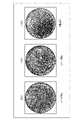
図8は、一般生菌検査の実験結果の例を示す図である。図8において、培地は標準寒天培地である。サンプルのpH(合成pH)は、10.0、10.5、11.0、11.5である。第1の容器3内の溶液13(原液)の0.1gを寒天培地に滴下した。培養は35℃で48時間行った。図8では、各サンプルについて1グラム当たりの菌のコロニーの数が表記されている。 FIG. 8 is a diagram showing an example of experimental results of a general viable bacteria test. In FIG. 8, the medium is standard agar medium. The sample pH (synthetic pH) is 10.0, 10.5, 11.0, 11.5. 0.1 g of the solution 13 (stock solution) in the
pHを10から10.5に上げると、菌のコロニー数がおよそ1/7に減少する。pHを10.5から11.0に上げると、菌のコロニー数がおよそ1/1.5に減少する。pHを11.0から11.5に上げると、菌のコロニー数がおよそ1/3に減少する。 Increasing the pH from 10 to 10.5 reduces the number of fungal colonies by approximately 1/7. Increasing the pH from 10.5 to 11.0 reduces the number of fungal colonies by approximately 1/1.5. Increasing the pH from 11.0 to 11.5 reduces the number of fungal colonies by approximately one-third.
図9は、一般生菌検査の結果に基づいて得られるpHと生菌増殖倍率との関係の例を示すグラフである。図9は、濃度測定作業時から第2の容器11詰め込み作業時までの間のpHごとの生菌増殖倍率を示す。 FIG. 9 is a graph showing an example of the relationship between pH and viable cell growth rate obtained based on the results of general viable cell inspection. FIG. 9 shows the growth rate of viable bacteria for each pH from the concentration measurement operation to the
図9から、生菌増殖率はpHが10.5以上になると大幅に減少することが分かる。 From FIG. 9, it can be seen that the growth rate of viable bacteria significantly decreases when the pH is 10.5 or higher.
上記の図8及び図9から、菌数の抑制においては、第1の容器3内の溶液13のpHが高いほど生菌数の抑制に効果があることが分かる。具体的には、第1の容器3内の溶液13のpHが10.5以上になると、生菌増殖の抑制効果が高まり、生菌数が大幅に減少する。 From FIG. 8 and FIG. 9 above, it can be seen that the higher the pH of the
第1の容器3内の溶液13のpHとHA収量率との関係を実験により求めると、第1の容器3内の溶液13のpHが上昇するほどHA収量率が低下した。 When the relationship between the pH of the
なお、HA収量率は、原料から算出される計算上のHA合成量に対する実際の生産量の率である。 Note that the HA yield rate is the ratio of the actual production amount to the calculated HA synthesis amount calculated from the raw materials.
以上の図8及び図9の実験結果と、溶液13のpHとHA収量率との関係の実験結果とより、生菌を抑制し、かつ、HA収量率を高くする溶液13のpHは、10以上12以下であった。 8 and 9 above, and the experimental results of the relationship between the pH of the
したがって、第1の実施形態に係る制御装置2は、第1の容器3内の溶液13のpHが10以上12以下の範囲に含まれるように制御を実行する。 Therefore, the
以上説明した第1の実施形態においては、HAの粒子サイズをナノサイズ程度に維持するために、溶液13を作製して濃縮し、濃縮されたHA懸濁液11を第2の容器12に収容し、第2の容器12を運搬する。 In the first embodiment described above, the
第1の実施形態においては、例えば、水酸化カルシウムの濃度、リン酸の濃度、リン酸の注入速度、溶液13の温度などの諸条件を調節することにより、粒子サイズが小さいHAを含む溶液13を作製して効率的に濃縮し、溶液13のpHを調節して菌数制御を実現することができる。 In the first embodiment, for example, by adjusting various conditions such as the concentration of calcium hydroxide, the concentration of phosphoric acid, the injection rate of phosphoric acid, and the temperature of the
第1の実施形態においては、HAが懸濁液に含まれている状態で出荷され、利用される。このため、HA粒子が凝集することを抑制することができ、粒子サイズの小さいHAを利用することができる。 In a first embodiment, HA is shipped and utilized in suspension. Therefore, aggregation of HA particles can be suppressed, and HA with a small particle size can be used.
第1の実施形態においては、濃縮を自然沈降により行う。ここで、第1の実施形態で用いる自然沈降と、比較例である遠心分離機による濃縮との相違点を説明する。遠心分離機を用いて溶液13を濃縮すると、HA粒子の凝集を招き、再分散が困難となる。これに対して、第1の実施形態においては、濃縮を自然沈降により行うためHA粒子が凝集することを抑制することができる。そして、濃縮することにより、HA懸濁液11の運搬を効率化して扱いやすくすることができる。 In a first embodiment, concentration is by spontaneous sedimentation. Here, differences between natural sedimentation used in the first embodiment and concentration by a centrifugal separator as a comparative example will be described. Concentrating the
なお、実験では、ナノサイズのHAを含む懸濁液に関しては、自然沈降により4倍程度の濃縮が可能であった。HAの粒子サイズがナノサイズではなくてもよい場合、懸濁液はおよそ15%程度まで濃縮可能であった。 In the experiment, it was possible to concentrate the suspension containing nano-sized HA by about four times due to natural sedimentation. Suspensions could be concentrated to around 15% if the HA particle size did not have to be nano-sized.
自然沈降に要する期間は、第1の容器3内の溶液13の温度によって変動する。例えば、実験では、濃度を3%程度まで濃縮する所要日数は9から28日間であった。自然沈降は、温度雰囲気に影響を受けることが200個の100L級のHA懸濁液11を作製したデータより得られた。この結果から、第1の実施形態において、制御装置2は、第1の容器3内の溶液13の温度が自然沈降に適した温度になるように制御を行う。第1の実施形態に係る作製装置1においては、自然沈降を5℃以上40℃以下で実施することにより沈降期間を短縮可能であった。したがって、第1の実施形態においては、溶液13を効率的に濃縮してHA懸濁液11を作製することができる。 The period required for natural sedimentation varies depending on the temperature of the
第1の実施形態においては、濃縮された懸濁液11を攪拌機37で攪拌した後に第2の容器12に収容する。このため、第1の実施形態においては、濃縮された懸濁液11の濃度を均一化することができる。 In the first embodiment, the
第1の実施形態においては、実験の結果、溶液13及び濃縮されたHA懸濁液11の保管温度を2℃以上30℃以下の範囲に制御することにより、菌数抑制の効果が得られた。
より好ましくは、溶液13及び濃縮されたHA懸濁液11の保管温度を2℃以上20℃以下の範囲に制御することにより菌数を抑制することができる。In the first embodiment, as a result of experiments, it was found that controlling the storage temperature of the
More preferably, the number of bacteria can be suppressed by controlling the storage temperature of the
このため、制御装置2及び温度調節装置8は、溶液13の温度、及び濃縮されたHA懸濁液11の温度を、2℃以上30℃以下の範囲、より好ましくは2℃以上20℃以下の範囲に制御してもよい。 For this reason, the
第1の実施形態において、制御装置2及び温度調節装置8は、沈降期間を短くするため、沈降期間の溶液13の温度を15℃以上25℃以下の範囲に制御し、沈降期間の経過後に、菌数抑制のために溶液13及び濃縮されたHA懸濁液11の温度を2℃以上20℃以下の範囲に制御してもよい。第1の実施形態において、温度調節装置8は、第1の容器3内の溶液13の温度調節に加えて、第2の容器12内の濃縮されたHA懸濁液11の温度調節も行うとしてもよい。この場合、制御装置2は、温度調節装置8を用いて、第2の容器12内の濃縮されたHA懸濁液11の温度を2℃以上20℃以下の範囲に制御してもよい。 In the first embodiment, in order to shorten the sedimentation period, the
第1の実施形態においては、自然沈降により溶液13を濃縮している。しかしながら、溶液13中のHAの分散性を維持するために非常に弱い遠心力を用いた遠心分離により濃縮を実行してもよい。さらに、第1の実施形態においては、自然沈降により濃縮されたHA懸濁液をさらに遠心分離機で弱い遠心力を使って濃縮してもよい。この場合、濃縮されたHA懸濁液内でHAを分散させるために、攪拌機37はHA懸濁液を激しく攪拌するとしてもよい。弱い遠心力を使用して濃縮を行う場合、6%程度までHAの凝集を抑制して濃縮されたHA懸濁液を作製することができる。 In the first embodiment, the
(第2の実施形態)
第2の実施形態においては、上記第1の実施形態によって作製されたHA懸濁液11を不織布に塗布する装置及び方法を説明する。第2の実施形態は、上記第1の実施形態と組み合わせて適用することができる。(Second embodiment)
In the second embodiment, an apparatus and method for applying the
第2の実施形態においては、AgHAの懸濁液に不織布を浸けることにより、AgHAを不織布に塗布する。第2の実施形態において、塗布とは、濡れと固化とを利用する技術であるとする。 In a second embodiment, AgHA is applied to the nonwoven fabric by soaking the nonwoven fabric in a suspension of AgHA. In the second embodiment, coating is assumed to be a technique using wetting and solidification.
なお、第2の実施形態においては、HAの一例としてAgHAを不織布に塗布する場合を説明するが、銀を含有しない他のHAを不織布に塗布する場合も同様の装置及び方法を適用することができる。具体的には、HAは、例えば、銅、パラジウム、白金、カドミウム、ニッケル、コバルト、亜鉛、マンガン、タリウム、鉛、水銀などの抗菌性重金属を含有するものでもよい。 In the second embodiment, as an example of HA, the case of applying AgHA to a nonwoven fabric will be described, but the same apparatus and method can be applied to the case of applying other HA that does not contain silver to a nonwoven fabric. can. Specifically, HA may contain antimicrobial heavy metals such as, for example, copper, palladium, platinum, cadmium, nickel, cobalt, zinc, manganese, thallium, lead, and mercury.
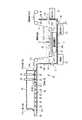
図10は、第2の実施形態に係るAgHAを不織布14に塗布する塗布装置15の構成の例を示す概念図である。図1は、塗布装置15の側面断面図を例示している。 FIG. 10 is a conceptual diagram showing an example of the configuration of the
塗布装置15は、主に、処理前の不織布14を送り出す送り出し部16、水槽部17、乾燥部18、処理後の不織布14を巻き取る巻き取り部19、液滴受け部20を備える。 The
連続する不織布14は、送り出し部16から送り出され、水槽部17のローラ211~214及び乾燥部18のローラ22により位置を調節され、巻き取り部19による巻き取りにより図10の左から右へ移動する。この図10の右から左への方向を不織布送り方向という。 The
水槽部17は、ローラ211~214と、水槽23と、第1のポンプ24と、第2のポンプ25と、シャワーヘッド26と、超音波振動子27と、冷却器28とを備える。 The
ローラ211とローラ212は、送り出し部16から送り出された不織布14を水槽23にためられているAgHAの懸濁液29(HA懸濁液11に相当)内へ誘導する。 The
ローラ212は、さらに、不織布14をシャワーヘッド26と超音波振動子27との間へ誘導する。
ローラ213とローラ214は、シャワーヘッド26と超音波振動子27との間を通過した不織布14を水槽23にためられている懸濁液29の外へ誘導する。 The
ローラ214は、さらに、不織布14に含まれている余分な懸濁液を不織布14から水槽23へ戻す。 The
水槽23は、懸濁液29を貯蔵する。水槽29は、第1の流出口30と、流入口31と、第2の流出口32とを備える。
第1の流出口30は、水槽23の第1の側面23aに備えられている。 The
流入口31は、水槽23の第2の側面23bに備えられている。第2の側面23bは、第1の側面23aに対向する面としてもよい。 The
第1のポンプ24は、第1の流出口30から水槽23外へ懸濁液29を排出し、懸濁液29を流入口31から水槽23内へ流入させる。これにより、水槽23内で懸濁液29が流動する。 The
第2の流出口32は、水槽23の底面23cに備えられている。 The
第2のポンプ25は、第2の流出口32から水槽23外へ懸濁液29を排出し、懸濁液29をシャワーヘッド26へ供給する。これにより、水槽23の深い位置に存在しAgHAの濃度の濃い懸濁液29をシャワーヘッド26へ供給し、懸濁液29をシャワーヘッド26から噴出させ、水槽23内で懸濁液29を流動させることができる。 The
シャワーヘッド26は、液体噴出面から懸濁液29を噴出する。シャワーヘッド26の液体噴出面は、超音波振動子27の振動面とギャップを介して対向する。
超音波振動子27は、超音波発生装置の一例である。超音波振動子27は、高周波数で振動して超音波放出面から超音波を放出する。超音波振動子27は、例えば、細胞破砕用の強力超音波を発する装置でもよい。超音波振動子27の超音波放出面は、シャワーヘッド26の液体排出面とギャップを介して対向する。 The
第2の実施形態においては、シャワーヘッド26が上、超音波振動子27が下に配置されている。 In the second embodiment, the
シャワーヘッド26の液体排出面と超音波振動子27の振動面との間のギャップは、例えば、不織布14の厚さより大きく、3mm以下であるとする。実験の結果から、ギャップは、例えば、6.5mm以下の範囲でも不織布14に懸濁液29を浸み込ませることが可能であった。超音波を強力にすること、及び/又は、懸濁液29の水流を強力にすることにより、ギャップは50mm以下の範囲で適用可能である。 Assume that the gap between the liquid discharge surface of the
シャワーヘッド26と超音波振動子27との間のギャップを通過した不織布14は、懸濁液29が浸み込んだ状態となる。 The
冷却器28は、超音波による水槽23内の懸濁液29の温度上昇を抑制する。より具体的には、冷却器28は、水槽23内の懸濁液29の温度が閾値を超えると動作し、懸濁液29の温度を下げる。
液滴受け部20は、水槽部17と乾燥部18との間に配置されている。液滴受け部20は、不織布14から垂れる懸濁液29の液滴を受ける。 The
乾燥部18は、筐体33と、複数のローラ22と、吹き出し口34と、支持台35とを備える。 The drying
筐体33のうち不織布14が搬入される側の面は、例えば透明なアクリル板33aとしてもよい。このように、透明なアクリル板33aを用いることで、オペレータは乾燥部18の内部の状態を容易に観察することができる。アクリル板33aは、不織布14を筐体33の外部から内部へ搬入するための開口部33cを有する。 The surface of the
筐体33のうち不織布14が搬出される側の面は、例えば柔軟性を有するシリコン板33bとしてもよい。シリコン板33bは、例えば、上部だけが筐体33の上面と接続されており、垂れ幕のような状態で配置される。オペレータは、このシリコン板33bを上げて筐体33の内部を設定及び変更できる。このように柔軟性を有するシリコン板33bを用いることで、オペレータは乾燥部18の内部の状態を容易に観察し、変更することができる。また、柔軟性を有するシリコン板33bを用いることで、筐体33内の空気などの気体を柔軟に排出することができる。シリコン板33bは、不織布14を筐体33の内部ら外部へ搬出するための開口部33dを有する。 The surface of the
複数のローラ22は、乾燥部18のアクリル板33aに形成されている開口部33cから搬入された不織布14を、乾燥部18のシリコン板33bに形成されている開口部33dから搬出されるように、移動させる。 The plurality of
吹き出し口34は、不織布14を乾燥させるための風(例えば温風)を排出する。第2の実施形態において、吹き出し口34は、筐体33内のアクリル板33a側において、不織布14の平面に対して垂直な方向で風を排出する。より具体的には、吹き出し口34は、筐体33の上面であり、筐体33の内部の不織布14の搬入側に設置されており、不織布14に対して下方向の風を排出する。第2の実施形態において、吹き出し口34の形状は、例えば円状が好ましいが、例えば楕円、四角形などのような他の形状でもよい。 The
不織布14の吹き出し口34側とは逆のローラ22側には、風を受けた不織布14がローラ22に巻き込まれることを防止するための支持台35が設置される。 On the
支持台35は、筐体33の内部であり、不織布14が風を受ける搬入側において不織布14を支える。 The
第2の実施形態において、支持台35の上面(不織布14を支える面)は網状であるとする。 In the second embodiment, the upper surface of the support base 35 (the surface supporting the nonwoven fabric 14) is assumed to be mesh-like.
図11は、シャワーヘッド26及び超音波振動子27の例を示す側面図である。 FIG. 11 is a side view showing an example of the
シャワーヘッド26と超音波振動子27は例えば不織布14の厚さより大きく3mm以下のギャップ36を介して対向するように備えられている。第2の実施形態では、シャワーヘッド26が上、超音波振動子27が下に備えられている。しかしながら、シャワーヘッド26が下、超音波振動子27が上など、他の配置関係が適用されてもよい。 The
シャワーヘッド26の下面には複数の孔が形成されている。シャワーヘッド26の下面の孔から懸濁液29が不織布14へ向けて噴出される。 A plurality of holes are formed in the bottom surface of the
超音波振動子27は、ギャップ36に存在する不織布14及び懸濁液29を超音波により振動させる。 The
水槽23内の懸濁液29に浸かった不織布14は気泡を含む。第2の実施形態においては、シャワーヘッド26から噴出された懸濁液29が不織布14に押し当てられる。懸濁液29の噴出と超音波振動子27から発生された超音波との相乗効果により不織布14から気泡が排出され、疎水性の不織布14が懸濁液29によって濡れる。 The
図12は、支持台35の上面の例を示す斜視図である。 FIG. 12 is a perspective view showing an example of the upper surface of the
支持台35の上面を網状とすることで、吹き付け口34から排出された風が不織布14を吹き抜ける効率をよくすることができ、さらに、不織布14が支持台35の下のロータ22に巻き込まれることを防止することができる。 By making the upper surface of the
図13は、第2の実施形態に係る塗布装置15によって実行されるAgHAを不織布14に塗布する方法の例を示すフローチャートである。 FIG. 13 is a flow chart showing an example of a method of applying AgHA to the
ステップS1301において、不織布14が、送り出し部16から水槽部17及び乾燥部18経由で巻き取り部19まで不織布送り方向に移動可能な状態で、塗布装置15にセットされる。 In step S1301, the
ステップS1302において、水槽23は懸濁液29をためる。 In step S 1302 , the
ステップS1303aにおいて、第1のポンプ24は、水槽23内の懸濁液29を循環させる。 In step S<b>1303 a , the
ステップS1303bにおいて、第2のポンプ25は、水槽23内の懸濁液29をシャワーヘッド26へ供給し、シャワーヘッド26から懸濁液29を噴出させる。 In step S<b>1303 b , the
ステップS1303cにおいて、超音波振動子27は、振動動作により不織布14に超音波を発し、不織布14から気泡を除去する。 In step S<b>1303 c , the
これらのステップS1303a~S1303cにより、懸濁液29が疎水性の不織布14にしみ込む。 Through these steps S1303a to S1303c, the
ステップS1304において、送り出し部16、ローラ211~214、ローラ22、巻き取り部19は、不織布送り方向に不織布14を移動させる。 In step S1304, the
ステップS1305において、乾燥部18は、吹き出し口34から排出される風により、懸濁液29がしみ込んでいる不織布14を乾燥させる。 In step S<b>1305 , the drying
以上説明した第2の実施形態の作用効果を説明する。 The effects of the second embodiment described above will be described.
乾燥されたAgHAよりも懸濁液29中のAgHAの方が粒子サイズは小さい。第2の実施形態では不織布14へ懸濁液29を浸み込ませて濡れ状態とし、その後乾燥させることで、不織布14へ粒子サイズの小さいAgHAを塗布する。 The AgHA in
不織布14が疎水性である場合、懸濁液29に不織布14を浸けただけでは十分に不織布14に懸濁液29がしみ込まず、十分に不織布14にAgHAを塗布することができない場合がある。 If the
そこで、第2の実施形態においては、超音波振動子27により不織布14を振動させ、シャワーヘッド26から不織布14に向けて懸濁液29を噴出して水流を発生させることにより、不織布14内から気泡を追い出し、不織布14が懸濁液29で濡れた状態とし、その後素早く不織布14を乾燥させる。第2の実施形態において、シャワーヘッド26は、均一な懸濁液29の噴出に加えて、気泡の追い出しにも関与する。 Therefore, in the second embodiment, the
これにより、懸濁成分である粒子サイズの小さいAgHAを不織布14に付着させることができる。 As a result, AgHA having a small particle size, which is a suspended component, can be adhered to the
第2の実施形態においては、超音波振動子27を用いて懸濁液29を振動させることにより水槽23内の懸濁液29の濃度を均一化することができる。 In the second embodiment, the concentration of the
第2の実施形態においては、互いに対向するシャワーヘッド26と超音波振動子27との間のギャップ36を不織布14が通過する。このギャップ36の幅を不織布14の厚さより大きく3mm以下とすることにより、不織布14への懸濁液29の浸み込みを促進することができる。 In the second embodiment, the
第2の実施形態においては、例えば懸濁液29の濃度を0.005%以上5.0%以下としてもよい。この場合、不織布14にAgHAを十分に付着させることができ、かつ、不織布14の繊維に過剰にAgHAが付着してAgHAの粉末が脱落することを防止することができる。 In the second embodiment, for example, the concentration of
懸濁液29の適切な濃度は、粒子サイズによって変わる。 The appropriate concentration of
AgHAがナノサイズである場合、AgHAがマイクロサイズである場合よりも不織布に細かいAgHAの粒子が均一に密着し、良好な塗布状態になる。 When AgHA is nano-sized, finer AgHA particles adhere more uniformly to the non-woven fabric than when AgHA is micro-sized, resulting in a good coating state.
水槽23中の懸濁液29の濃度が所定値以上となるように、水槽23に懸濁液29が補充されてもよい。 The
第2の実施形態においては、シャワーヘッド26から噴出される懸濁液29の流量を調整し、かつ、超音波振動子27により不織布14に超音波を当てることにより、効率的に不織布14内の気泡を排出して不織布14を懸濁液29により濡れ状態にすることができる。 In the second embodiment, by adjusting the flow rate of the
第2の実施形態においては、AgHAを不織布14に塗布する場合を説明しているが、AgHAに代えてHAを不織布14に塗布する場合も同様の装置及び方法を適用することができる。 In the second embodiment, the case of applying AgHA to the
第2の実施形態においては、シャワーヘッド26と超音波振動子27とを用いて疎水性の不織布14を濡れ状態としている。しかしながら、不織布が親水性の場合、超音波振動子27を用いなくても不織布を濡れ状態とすることができる。 In the second embodiment, a
第2の実施形態において、不織布14は、シャワーヘッド26と超音波振動子27との間を通過し、ローラ214で不織布14に付いている余分な懸濁液が搾り取られ、水槽23に戻る。そして、適度に濡れた不織布14は乾燥部18の内部へ搬送される。このようにシャワーヘッド26から懸濁液29を噴出することにより、不織布14の濡れの効率を向上させることができ、水槽23内の懸濁液29を攪拌することができる。 In the second embodiment, the
第2の実施形態においては、シャワーヘッド26によって生じる流れに加えて、第1の流出口30から流出された懸濁液29を流入口31から流入させることで、さらに、水槽23内の懸濁液29を攪拌及び循環させることができる。これにより、水槽23内の懸濁液29の濃度を均一化することができ、不織布14にAgHAを均一に塗布することができる。 In the second embodiment, in addition to the flow generated by the
上記の実施形態は、例示であり、発明の範囲を限定することは意図していない。上記の実施形態は、その他の様々な形態で実施されることが可能であり、発明の要旨を逸脱しない範囲で種々の省略、置き換え、変更を行うことができる。上記の実施形態やその変形は、発明の範囲や要旨に含まれると同様に、特許請求の範囲に記載された発明とその均等の範囲に含まれるものである。 The above embodiments are examples and are not intended to limit the scope of the invention. The above embodiments can be implemented in various other forms, and various omissions, replacements, and modifications can be made without departing from the scope of the invention. The above-described embodiments and modifications thereof are included in the scope and spirit of the invention, as well as the scope of the invention described in the claims and equivalents thereof.
Claims (8)
Translated fromJapanese前記容器に水酸化カルシウムを注入する第1の注入装置と、
前記容器に収容されている溶液にリン酸を注入する第2の注入装置と、
前記容器内の前記溶液のpHを計測するpH計と、
前記pH計によって計測された前記pHが所定の範囲になるように、前記第1の注入装置によって注入される前記水酸化カルシウムの濃度と、前記第2の注入装置によって注入される前記リン酸の濃度と注入速度とのうちの少なくとも一方とを制御する制御装置と、
前記容器内の前記溶液の自然沈降によって濃縮されたハイドロキシアパタイト懸濁液を前記容器の外に注出する注出装置と、
前記容器内の前記溶液の温度を計測する温度計と、
前記容器内の前記溶液を加熱又は冷却する温度調節装置と、
を具備し、
前記制御装置は、前記自然沈降時に、前記温度計によって計測される前記温度が15℃以上25℃以下の範囲になるように前記温度調節装置を制御し、前記自然沈降の後に前記温度が2℃以上20℃以下の範囲になるように前記温度調節装置を制御する、ハイドロキシアパタイト懸濁液の作製装置。a container;
a first injection device for injecting calcium hydroxide into the container;
a second injection device for injecting phosphoric acid into the solution contained in the container;
a pH meter for measuring the pH of the solution in the container;
The concentration of the calcium hydroxide injected by the first injection device and the phosphoric acid injected by the second injection device are adjusted so that the pH measured by the pH meter falls within a predetermined range. a controller for controlling at least one of concentration and injection rate;
a pouring device for pouring out of the container a hydroxyapatite suspension concentrated by natural sedimentation of the solution in the container;
a thermometer for measuring the temperature of the solution in the container;
a temperature control device that heats or cools the solution in the container;
and
The control device controls the temperature control device so that the temperature measured by the thermometer is in the range of 15 ° C. or higher and 25 ° C. or lower during the natural settling, and the temperature is 2 ° C. after the natural settling. An apparatus for producinga hydroxyapatite suspension, wherein the temperature control device is controlled so that the temperature is in the range of 20° C. or more and 20° C. or less .
前記容器内の前記沈降部分を攪拌する撹拌機をさらに具備し、
前記注出装置は、攪拌された前記沈降部分を前記濃縮されたハイドロキシアパタイト懸濁液として前記容器の外に注出する、
請求項1の作製装置。The pouring device pours out a supernatant portion of the solution from the container after the natural sedimentation of the solution, leaving the sedimented portion of the solution in the container,
further comprising a stirrer for stirring the sedimentation portion in the container;
The pouring device pours the stirred sedimented portion out of the container as the concentrated hydroxyapatite suspension.
The fabrication apparatus of claim 1.
前記容器に水酸化カルシウムを注入する第1の注入装置と、
前記容器に収容されている前記水酸化カルシウムを含む溶液にリン酸を注入する第2の注入装置と、
前記容器内の前記溶液のpHを計測するpH計と、
前記pH計によって計測された前記pHが所定の範囲になるように、前記第1の注入装置によって注入される前記水酸化カルシウムの濃度と、前記第2の注入装置によって注入される前記リン酸の濃度と注入速度とのうちの少なくとも一方とを制御する制御装置と、
前記容器内の前記溶液の自然沈降によって濃縮されたハイドロキシアパタイト懸濁液を前記容器の外に注出する注出装置と、
を具備し、
前記制御装置は、前記pH計によって計測された前記pHが前記所定の範囲になった後に、再び前記第2の注入装置に前記リン酸の滴下を実行させ、前記pH計によって計測された前記pHが安定したと判断した場合に、前記リン酸の滴下を終了し、
前記濃縮されたハイドロキシアパタイト懸濁液は、カルシウム欠損型ハイドロキシアパタイトを含む、ハイドロキシアパタイト懸濁液の作製装置。a container;
a first injection device for injecting calcium hydroxide into the container;
a second injection device for injecting phosphoric acid into the solution containing calcium hydroxide contained in the container;
a pH meter for measuring the pH of the solution in the container;
The concentration of the calcium hydroxide injected by the first injection device and the phosphoric acid injected by the second injection device are adjusted so that the pH measured by the pH meter falls within a predetermined range. a controller for controlling at least one of concentration and injection rate;
a pouring device for pouring out of the container a hydroxyapatite suspension concentrated by natural sedimentation of the solution in the container;
and
After the pH measured by the pH meter reaches the predetermined range, the control device causes the second injection device to drip the phosphoric acid again, and the pH measured by the pH meter When it is determined that the is stable, stop dropping the phosphoric acid,
An apparatusfor producing a hydroxyapatite suspension, wherein the concentrated hydroxyapatite suspension contains calcium-deficient hydroxyapatite .
前記容器に水酸化カルシウムを注入する第1の注入装置と、
前記容器に収容されている前記水酸化カルシウムを含む溶液にリン酸を注入する第2の注入装置と、
前記容器内の前記溶液のpHを計測するpH計と、
前記pH計によって計測された前記pHが所定の範囲になるように、前記第1の注入装置によって注入される前記水酸化カルシウムの濃度と、前記第2の注入装置によって注入される前記リン酸の濃度と注入速度とを制御する制御装置と、
前記容器内の前記溶液の自然沈降によって濃縮されたハイドロキシアパタイト懸濁液を前記容器の外に注出する注出装置と、
を具備し、
前記制御装置は、前記第2の注入装置によって注入される前記リン酸の注入速度が0.1ml/min/g以上10ml/min/g以下になるように制御を行う、
ハイドロキシアパタイト懸濁液の作製装置。a container;
a first injection device for injecting calcium hydroxide into the container;
a second injection device for injecting phosphoric acid into the solution containing calcium hydroxide contained in the container;
a pH meter for measuring the pH of the solution in the container;
The concentration of the calcium hydroxide injected by the first injection device and the phosphoric acid injected by the second injection device are adjusted so that the pH measured by the pH meter falls within a predetermined range. a controller for controlling concentration and injection rate;
a pouring device for pouring out of the container a hydroxyapatite suspension concentrated by natural sedimentation of the solution in the container;
and
The control device controls the injection rate of the phosphoric acid injected by the second injection device to be 0.1 ml/min/g or more and 10 ml/min/g or less.
An apparatusfor producing a hydroxyapatite suspension .
第2の注入装置により前記容器に収容されている溶液にリン酸を注入することと、
pH計により前記容器内の前記溶液のpHを計測することと、
制御装置により、前記pH計によって計測された前記pHが所定の範囲になるように、前記第1の注入装置によって注入される前記水酸化カルシウムの濃度と、前記第2の注入装置によって注入される前記リン酸の濃度と注入速度とのうちの少なくとも一方とを制御することと、
注出装置により前記容器内の前記溶液の自然沈降によって濃縮されたハイドロキシアパタイト懸濁液を前記容器の外に注出することと、
を具備し、
前記制御することは、前記自然沈降時に、温度計によって計測される前記容器内の前記溶液の温度が15℃以上25℃以下の範囲になるように、前記容器内の前記溶液を加熱又は冷却する温度調節装置を制御し、前記自然沈降の後に前記温度が2℃以上20℃以下の範囲になるように前記温度調節装置を制御することをさらに具備する、ハイドロキシアパタイト懸濁液の作製方法。injecting calcium hydroxide into the container with a first injection device;
injecting phosphoric acid into the solution contained in the container with a second injection device;
measuring the pH of the solution in the container with a pH meter;
The controller controls the concentration of the calcium hydroxide injected by the first injection device and the concentration of the calcium hydroxide injected by the second injection device so that the pH measured by the pH meter falls within a predetermined range. controlling at least one of the phosphoric acid concentration and injection rate;
pouring out of the container a hydroxyapatite suspension concentrated by natural sedimentation of the solution in the container by a pouring device;
and
The controlling includes heating or cooling the solution in the container so that the temperature of the solution in the container measured by a thermometer is in the range of 15° C. or higher and 25° C. or lower during the natural sedimentation. A method for producinga hydroxyapatite suspension, further comprising controlling a temperature control device so that the temperature after the natural settling falls within a range of 2° C. or higher and 20° C. or lower .
第2の注入装置により前記容器に収容されている溶液にリン酸を注入することと、 injecting phosphoric acid into the solution contained in the container with a second injection device;
pH計により前記容器内の前記溶液のpHを計測することと、 measuring the pH of the solution in the container with a pH meter;
制御装置により、前記pH計によって計測された前記pHが所定の範囲になるように、前記第1の注入装置によって注入される前記水酸化カルシウムの濃度と、前記第2の注入装置によって注入される前記リン酸の濃度と注入速度とのうちの少なくとも一方とを制御することと、 The controller controls the concentration of the calcium hydroxide injected by the first injection device and the concentration of the calcium hydroxide injected by the second injection device so that the pH measured by the pH meter falls within a predetermined range. controlling at least one of the phosphoric acid concentration and injection rate;
注出装置により前記容器内の前記溶液の自然沈降によって濃縮されたハイドロキシアパタイト懸濁液を前記容器の外に注出することと、 pouring out of the container a hydroxyapatite suspension concentrated by natural sedimentation of the solution in the container by a pouring device;
を具備し、and
前記制御することは、前記pH計によって計測された前記pHが前記所定の範囲になった後に、再び前記第2の注入装置に前記リン酸の滴下を実行させ、前記pH計によって計測された前記pHが安定したと判断した場合に、前記リン酸の滴下を終了することをさらに具備し、 The controlling includes causing the second injection device to drop the phosphoric acid again after the pH measured by the pH meter reaches the predetermined range, and the pH measured by the pH meter Further comprising terminating the dropping of the phosphoric acid when it is determined that the pH is stable,
前記濃縮されたハイドロキシアパタイト懸濁液は、カルシウム欠損型ハイドロキシアパタイトを含む、ハイドロキシアパタイト懸濁液の作製方法。 A method for producing a hydroxyapatite suspension, wherein the concentrated hydroxyapatite suspension contains calcium-deficient hydroxyapatite.
第2の注入装置により前記容器に収容されている溶液にリン酸を注入することと、 injecting phosphoric acid into the solution contained in the container with a second injection device;
pH計により前記容器内の前記溶液のpHを計測することと、 measuring the pH of the solution in the container with a pH meter;
制御装置により、前記pH計によって計測された前記pHが所定の範囲になるように、前記第1の注入装置によって注入される前記水酸化カルシウムの濃度と、前記第2の注入装置によって注入される前記リン酸の濃度と注入速度とを制御することと、 The controller controls the concentration of the calcium hydroxide injected by the first injection device and the concentration of the calcium hydroxide injected by the second injection device so that the pH measured by the pH meter falls within a predetermined range. controlling the concentration and injection rate of the phosphoric acid;
注出装置により前記容器内の前記溶液の自然沈降によって濃縮されたハイドロキシアパタイト懸濁液を前記容器の外に注出することと、 pouring out of the container a hydroxyapatite suspension concentrated by natural sedimentation of the solution in the container by a pouring device;
を具備し、and
前記制御することは、前記第2の注入装置によって注入される前記リン酸の注入速度が0.1ml/min/g以上10ml/min/g以下になるように制御を行う、ハイドロキシアパタイト懸濁液の作製方法。 The hydroxyapatite suspension, wherein the controlling is performed so that the injection rate of the phosphoric acid injected by the second injection device is 0.1 ml/min/g or more and 10 ml/min/g or less. method of making.
Applications Claiming Priority (1)
| Application Number | Priority Date | Filing Date | Title |
|---|---|---|---|
| PCT/JP2022/017239WO2023195119A1 (en) | 2022-04-07 | 2022-04-07 | Apparatus and method for preparing hydroxyapatite suspension |
Publications (3)
| Publication Number | Publication Date |
|---|---|
| JP7162955B1true JP7162955B1 (en) | 2022-10-31 |
| JPWO2023195119A1 JPWO2023195119A1 (en) | 2023-10-12 |
| JPWO2023195119A5 JPWO2023195119A5 (en) | 2024-03-14 |
Family
ID=83845920
Family Applications (1)
| Application Number | Title | Priority Date | Filing Date |
|---|---|---|---|
| JP2022554210AActiveJP7162955B1 (en) | 2022-04-07 | 2022-04-07 | Apparatus and method for preparing hydroxyapatite suspension |
Country Status (4)
| Country | Link |
|---|---|
| US (1) | US20240336483A1 (en) |
| JP (1) | JP7162955B1 (en) |
| CN (1) | CN118475535A (en) |
| WO (1) | WO2023195119A1 (en) |
Citations (5)
| Publication number | Priority date | Publication date | Assignee | Title |
|---|---|---|---|---|
| JP2006528894A (en)* | 2003-05-22 | 2006-12-28 | アートス ゲーエムベーハー | Resorbable inorganic bone replacement material |
| JP2007075595A (en)* | 2005-08-19 | 2007-03-29 | San Medical Gijutsu Kenkyusho:Kk | Sheet-like covering member used for implant medical device |
| JP2010273847A (en)* | 2009-05-28 | 2010-12-09 | Tokyo Institute Of Technology | High density porous composite |
| WO2018198296A1 (en)* | 2017-04-27 | 2018-11-01 | ブレイニー株式会社 | Hydroxyapatite, cosmetic, food, and method for producing same |
| JP2019155209A (en)* | 2018-03-07 | 2019-09-19 | 住友金属鉱山株式会社 | Treatment facility and treatment method of boron-containing water |
- 2022
- 2022-04-07JPJP2022554210Apatent/JP7162955B1/enactiveActive
- 2022-04-07WOPCT/JP2022/017239patent/WO2023195119A1/ennot_activeCeased
- 2022-04-07CNCN202280086907.7Apatent/CN118475535A/enactivePending
- 2024
- 2024-06-17USUS18/744,899patent/US20240336483A1/enactivePending
Patent Citations (5)
| Publication number | Priority date | Publication date | Assignee | Title |
|---|---|---|---|---|
| JP2006528894A (en)* | 2003-05-22 | 2006-12-28 | アートス ゲーエムベーハー | Resorbable inorganic bone replacement material |
| JP2007075595A (en)* | 2005-08-19 | 2007-03-29 | San Medical Gijutsu Kenkyusho:Kk | Sheet-like covering member used for implant medical device |
| JP2010273847A (en)* | 2009-05-28 | 2010-12-09 | Tokyo Institute Of Technology | High density porous composite |
| WO2018198296A1 (en)* | 2017-04-27 | 2018-11-01 | ブレイニー株式会社 | Hydroxyapatite, cosmetic, food, and method for producing same |
| JP2019155209A (en)* | 2018-03-07 | 2019-09-19 | 住友金属鉱山株式会社 | Treatment facility and treatment method of boron-containing water |
Also Published As
| Publication number | Publication date |
|---|---|
| CN118475535A (en) | 2024-08-09 |
| JPWO2023195119A1 (en) | 2023-10-12 |
| US20240336483A1 (en) | 2024-10-10 |
| WO2023195119A1 (en) | 2023-10-12 |
Similar Documents
| Publication | Publication Date | Title |
|---|---|---|
| JP5792652B2 (en) | Stirring device, discharge device including the same, and discharge method | |
| EP2314647A1 (en) | Method and device for producing a coating material | |
| CN111905898B (en) | Preparation device and use method of anti-corrosion coating | |
| JP7162955B1 (en) | Apparatus and method for preparing hydroxyapatite suspension | |
| RU2523643C2 (en) | Production of suspensions of metal and metal compounds superfine particles and device to this end | |
| CN103657537B (en) | For the preparation of equipment and the method for the drop be present in gas phase | |
| US7811526B2 (en) | Device for recovering feedstock liquid, device for supplying a feedstock liquid, device for solidifying the surfaces of drops, and apparatus for producing ammonium diuranate particles | |
| WO2023209788A1 (en) | Apparatus and method for producing hydroxyapatite containing antibacterial metal | |
| JP2024012323A (en) | Antibacterial metal-containing hydroxyapatite production device | |
| KR102024691B1 (en) | Apparatus and method for treating fabric | |
| US20130041172A1 (en) | Apparatus for removing catalyst surface substances | |
| CN112076872A (en) | Grinding and mixing system, preparation method of composite material and mixing method | |
| JP6536884B2 (en) | Modification method of metal surface using micro and nano bubble and adhesion method of metal and resin | |
| US20130065968A1 (en) | Gel production apparatus and gel production method | |
| CN110961164B (en) | Catalyst continuous impregnation equipment and method and application thereof | |
| US20240309579A1 (en) | Apparatus and method for applying hydroxyapatite to nonwoven fabric | |
| TWI417382B (en) | Aliginate microbeads, method for forming the same and associated applications | |
| CN209348461U (en) | A kind of powder batch mixer | |
| EP3162568A1 (en) | Inkjet head and application device in which same is used | |
| CN112221806B (en) | Ultrasonic atomization spraying device with good solution dispersion and application method thereof | |
| JPS61212318A (en) | Generating method for fine air foam | |
| JP7448276B1 (en) | Apparatus and method for forming hydroxyapatite-containing thin film | |
| US20250064694A1 (en) | Methods of forming dry-to-the-touch peroxide compositions | |
| JP2025082550A (en) | Processing apparatus and method | |
| CN213132835U (en) | Automatic agitating unit of pesticide is sprayed in aviation |
Legal Events
| Date | Code | Title | Description |
|---|---|---|---|
| A521 | Request for written amendment filed | Free format text:JAPANESE INTERMEDIATE CODE: A523 Effective date:20220907 | |
| A621 | Written request for application examination | Free format text:JAPANESE INTERMEDIATE CODE: A621 Effective date:20220907 | |
| A871 | Explanation of circumstances concerning accelerated examination | Free format text:JAPANESE INTERMEDIATE CODE: A871 Effective date:20220907 | |
| TRDD | Decision of grant or rejection written | ||
| A01 | Written decision to grant a patent or to grant a registration (utility model) | Free format text:JAPANESE INTERMEDIATE CODE: A01 Effective date:20221004 | |
| A61 | First payment of annual fees (during grant procedure) | Free format text:JAPANESE INTERMEDIATE CODE: A61 Effective date:20221012 | |
| R150 | Certificate of patent or registration of utility model | Ref document number:7162955 Country of ref document:JP Free format text:JAPANESE INTERMEDIATE CODE: R150 | |
| R250 | Receipt of annual fees | Free format text:JAPANESE INTERMEDIATE CODE: R250 |