JP7162285B1 - Communication method and communication system - Google Patents
Communication method and communication systemDownload PDFInfo
- Publication number
- JP7162285B1 JP7162285B1JP2022036640AJP2022036640AJP7162285B1JP 7162285 B1JP7162285 B1JP 7162285B1JP 2022036640 AJP2022036640 AJP 2022036640AJP 2022036640 AJP2022036640 AJP 2022036640AJP 7162285 B1JP7162285 B1JP 7162285B1
- Authority
- JP
- Japan
- Prior art keywords
- display
- data
- visible light
- light
- unit
- Prior art date
- Legal status (The legal status is an assumption and is not a legal conclusion. Google has not performed a legal analysis and makes no representation as to the accuracy of the status listed.)
- Active
Links
- 238000004891communicationMethods0.000titleclaimsabstractdescription98
- 238000000034methodMethods0.000titleclaimsdescription25
- 238000003860storageMethods0.000claimsdescription19
- 230000004397blinkingEffects0.000claimsdescription6
- 238000010586diagramMethods0.000abstractdescription15
- 238000007726management methodMethods0.000description146
- 230000003287optical effectEffects0.000description37
- 230000005540biological transmissionEffects0.000description26
- 238000000060site-specific infrared dichroism spectroscopyMethods0.000description22
- 238000012545processingMethods0.000description17
- 238000012790confirmationMethods0.000description13
- 230000006870functionEffects0.000description11
- 230000008859changeEffects0.000description6
- 239000000463materialSubstances0.000description6
- 230000010365information processingEffects0.000description5
- 239000002994raw materialSubstances0.000description5
- 238000001514detection methodMethods0.000description4
- 238000003825pressingMethods0.000description4
- 230000008901benefitEffects0.000description3
- 238000002360preparation methodMethods0.000description3
- 230000008569processEffects0.000description3
- 238000013068supply chain managementMethods0.000description3
- 238000012384transportation and deliveryMethods0.000description3
- 238000005516engineering processMethods0.000description2
- 238000004519manufacturing processMethods0.000description2
- 230000001360synchronised effectEffects0.000description2
- 239000002390adhesive tapeSubstances0.000description1
- 230000003247decreasing effectEffects0.000description1
- 238000009826distributionMethods0.000description1
- 239000004744fabricSubstances0.000description1
- 239000004973liquid crystal related substanceSubstances0.000description1
- 230000007774longtermEffects0.000description1
- 238000012986modificationMethods0.000description1
- 230000004048modificationEffects0.000description1
- 238000012544monitoring processMethods0.000description1
Images


Landscapes
- Selective Calling Equipment (AREA)
- Arrangements For Transmission Of Measured Signals (AREA)
Abstract
Translated fromJapaneseDescription
Translated fromJapanese本発明は、通信方法および通信システムに係り、特にIOT(Internet of Things)に用いられる通信に関する。 The present invention relates to a communication method and communication system, and more particularly to communication used in IOT (Internet of Things).
測定対象物の近傍にセンサを配置し、センサが検知したデータを、無線ネットワークを通じて収集するIoT(Internet of Things)の利用が進んでいる。例えば、特許文献1には、センサが検知したデータを自動受信および送信できる無線通信デバイスが開示されている。また、センサを用いた物品管理に関して言えば、特許文献2には、被検出物に取り付けた非接触無線ICタグをリーダアンテナ部で受信し、受信したICタグ情報および位置検知情報を基地局に無線通信することで在庫管理を行う在庫品管理システムが開示されている。 2. Description of the Related Art IoT (Internet of Things), in which sensors are arranged in the vicinity of an object to be measured and data detected by the sensors is collected through a wireless network, is being used. For example,
例えば、アパレル業界では、従業員が数人規模の中小企業や個人経営が多く、彼らが、材料の仕入れ、衣服の製造、販売或いは大手アパレル企業への納品、等すべてを行わなければならない。もちろん、彼らがこれらの作業に伴う材料や製造品の在庫管理も行う必要がある。 For example, in the apparel industry, there are many small and medium-sized enterprises with several employees and individual businesses, and they have to purchase materials, manufacture and sell clothes, or deliver them to major apparel companies. Of course, they also need to manage the inventory of materials and manufactured goods that accompany these operations.
その一対応として、特許文献2に記載のように、ICタグを用いて材料や製造品の在庫管理を行う案がある。然しながら、材料や製造品へのICタグの付与、そのための無線設備の設置、ICタグ情報を処理する情報処理システムの構築等に多額の費用を要する。また、日々の運用にも手間がかかるので、中小企業や個人業者にとっては実現が容易でない。また、作業者が情報処理技術やそのオペレーションに精通しているとは言い難い。そこで、情報処理技術に不慣れな人でも、あまり負荷がかからずに、簡便な手段で在庫等の物品の管理が実現可能なシステムが望まれる。 As one countermeasure, as described in Patent Document 2, there is a proposal to manage the inventory of materials and manufactured products using IC tags. However, attaching IC tags to materials and manufactured products, installing radio equipment therefor, and constructing an information processing system for processing IC tag information requires a large amount of money. In addition, it is not easy for small and medium-sized enterprises and sole proprietors to implement the system because it takes time and effort to operate it on a daily basis. Moreover, it is difficult to say that the workers are well versed in information processing technology and its operation. Therefore, there is a demand for a system in which even a person unfamiliar with information processing technology can manage articles such as inventory by a simple means without imposing a heavy load.
本発明の目的は、端末とデバイスとの間のデータ通信を容易に行うことにある。 An object of the present invention is to facilitate data communication between a terminal and a device.
本発明に係る通信方法の好ましい一例は、デバイスと端末との間の通信方法であって、
前記デバイスは、可視光を受光する受光素子を有し、
前記端末は、発光手段と、制御部とを有し、
前記デバイスの前記受光素子に対応して、前記端末の前記発光手段を位置付けるステップと、
前記制御部が、前記発光手段を点滅させて、情報を可視光送信するステップと、
前記デバイスの前記受光素子が、前記発光手段から送信された前記情報を受信するステップと、
を有する通信方法、である。A preferable example of the communication method according to the present invention is a communication method between a device and a terminal,
The device has a light receiving element that receives visible light,
The terminal has a light emitting means and a control unit,
positioning the light emitting means of the terminal corresponding to the light receiving element of the device;
a step in which the control unit blinks the light emitting means to transmit information with visible light;
the light receiving element of the device receiving the information transmitted from the light emitting means;
A communication method comprising:
また、本発明に係る通信方法の好ましい一例は、第1の装置と第2の装置との間の通信方法であって、
前記第1の装置は、可視光を受光する受光素子を有し、
前記第2の装置は、表示部と、制御部とを有し、
前記第1の装置の前記受光素子と、前記第2の装置が有する前記表示部の表示画面を対応させるステップと、
前記制御部が、前記表示部の前記表示画面を点滅させて、データを可視光送信するステップと、
前記第1の装置の前記受光素子が、可視光送信された前記データを受信するステップと、
を有する通信方法、である。
本発明はまた、上記通信方法を実現する通信システムとして把握される。A preferable example of the communication method according to the present invention is a communication method between a first device and a second device,
The first device has a light receiving element that receives visible light,
The second device has a display unit and a control unit,
a step of associating the light-receiving element of the first device with the display screen of the display unit of the second device;
a step in which the control unit blinks the display screen of the display unit to transmit data with visible light;
a step in which the light receiving element of the first device receives the data transmitted by visible light;
A communication method comprising:
The present invention is also understood as a communication system that implements the above communication method.
本発明によれば、端末とデバイスとの間のデータ通信を容易に行うことができる。 According to the present invention, data communication between a terminal and a device can be easily performed.
以下、本発明の好ましい実施形態について図面を参照して詳細に説明する。 Preferred embodiments of the present invention will now be described in detail with reference to the drawings.
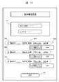
図1は、本実施例によるデバイス管理システムの構成を示す図である。
デバイス管理システムは、複数のデバイス10と、スマートフォンやタブレット端末のような携帯端末(以下単に端末という)13と、管理サーバ12が、無線LAN18のような無線ネットワークおよびネットワーク(公衆網)19により接続されて構成される。FIG. 1 is a diagram showing the configuration of a device management system according to this embodiment.
In the device management system, a plurality of
ここで、デバイス10は、対象物又はその状態を検知するセンサデバイスであってよい。また、対象として温度、湿度、振動などを測定するセンサであってよい。デバイス10の検知データは、Wifi(Wireless Fidelity)18のような無線LANおよびネットワーク19を介して、管理サーバ12へ送信される。本実施例では、物品の在庫管理に適用するため、デバイスは物品の数(計数)を取得(入力)するカウンタである。カウンタは、ユーザの操作が容易で低コストで実現できる簡単な構成である。カウンタの詳細については、図2を参照して後述する。在庫管理の場合、複数のカウンタが例えば、衣料品の材料(例えば種類の異なる糸や布)や製作済みの衣服などの物品を保管する棚にそれぞれ配置される。原材料が収納された段ボール箱が棚や倉庫に置かれる場合には、カウンタであるデバイス10の背面に両面接着テープを貼って、そのデバイス10を段ボールの側面等に固定してもよい。 Here, the
端末13は、管理サーバ12およびデバイス10との間で通信して、管理サーバ12で管理されるデータを取得し、またデバイス10に対してデータの送信を行う。デバイス10との通信手段は例えば、端末13の簡単な操作で行える可視光通信である。端末13の詳細については、図3を参照して後述する。 The
管理サーバ12は、一例ではデバイス10の管理および物品の在庫状況の管理を行う処理部(CPU)及び記憶部を有する情報処理装置である。管理サーバ12の詳細については、図4を参照して後述する。 The
<デバイス10>
図2は、デバイス10の構成を示す図である。
デバイス10は、制御部22、無線通信部23、カウンタボタン211,212(総じて21と示す)、表示部24、光素子261,262(総じて26と示す)、電源ボタン27を有し、カウンタの機能を実現する。制御部22は、処理部(CPU)221、メモリ222、光素子26を制御する光素子制御部223を有する。表示部24は例えば液晶表示器であり、カウンタ値や設定データ等を表示する。光素子26は受光素子(光学手段)であり、端末10との間で可視光通信を行う。一例では、光素子261はクロック同期用の受光素子であり、光素子262はクロックに同期してデータを受信する受光素子である。なお、光素子26は可視光素子と呼んでもよい。<
FIG. 2 is a diagram showing the configuration of the
The
無線通信部23は、Wifi18を介して管理サーバ12に対して無線通信する。電源ボタン27は、デバイス10の電源オン・オフを切り替えるボタンである。なお、電池をセットした状態で電源オンになるように設定すれば、電源ボタン27は必ずしも必要としない。デバイス10は電池(例えば2本の単4電池)で駆動される(電池の図示は省略)。 The
カウンタボタン211は加算ボタンであり、1回押下されるごとにカウンタ値を「1」加算する。カウンタボタン212は減算ボタンで1回押下されるごとにカウンタ値を「1」減算する。物品の在庫管理の場合、ユーザ(作業者)は、対象の物品が置かれた棚から物品を1つ取り出すごとに減算ボタン212を押下し、対象の物品を1つ追加するごとに加算ボタン211を押下する。加算ボタン211または減算ボタン212が押下されたことを、制御部22の処理部221が検知すると、メモリ222に記憶されるカウンタの値を更新して、更新した値(現在値)を表示部24に表示する。このように本実施例によれば、ユーザがカウンタボタン21を押下するという簡単な操作で、在庫数を管理することが可能となる。また、在庫管理のためのシステムの構築を容易に安価に実現できる。 The
制御部22において、メモリ222はデバイス10の管理情報(後述するWifiのSSIDやパスワード)や初期値、およびカウンタ値をそれぞれ別々の記憶エリアに記憶する。また、メモリ222は、デバイス10ごとに予め付与された固有のデバイスIDを記憶している。 In the
処理部221はプログラムを実行して、各部位を制御し、種々のデータ処理を行う。例えば、カウンタボタン21の押下を検知してメモリ222内のカウンタ値を更新する処理、表示部24へデータを表示する表示制御、端末13との間で可視光通信するための光素子制御部223の制御、デバイス10の管理情報や初期値をメモリ222に設定する処理、無線通信部23を介して管理サーバ12との間でのデータ通信、等の種々の処理を行う。なお、光素子制御部223は、メモリ222に格納された可視光通信制御プログラムをCPU221が実行することで実現される。一例では、管理サーバ12が管理する物品ごとの最新の値(現在値)のデータは、ネットワーク19およびWifi18を介して受信して、メモリ222に格納するように制御される。 The
本実施例において、デバイス10への管理情報およびカウンタの初期値の送信は、端末13とデバイス10の光素子26との間で可視光通信により行なわれる。例えば、デバイス10がWifi18を介して管理サーバ12と通信を行う例では、端末13にWifiのSSIDやパスワード(暗号キー)等の管理情報を入力して記憶部34に格納しておき、端末13とデバイス10の光素子26との間で可視光通信を行って、デバイス10のメモリ222に管理情報を設定する。また、初期設定時に、管理サーバ12が管理する物品ごとの初期値のデータをメモリ222に格納する。ここで、この可視光通信を可視光通信インタフェースということにする。 In this embodiment, transmission of the management information and the initial value of the counter to the
<端末13>
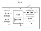
図3は、端末13の構成を示す図である。
端末13は例えばスマートフォンやタブレット端末であり、入力部31、表示部32、制御部33、記憶部34、無線通信部35を有して構成される。情報を表示する表示部とユーザの操作による入力を受付ける入力部は例えばタッチパネルディスプレイで構成される。記憶部34は、入力部31や無線通信部35を介して管理サーバ12から取得したデータ(例えば管理情報や初期値、在庫データ)や種々のプログラムを保管する。無線通信部35は、Wifiやインターネットを介して通信を可能とする。<
FIG. 3 is a diagram showing the configuration of the terminal 13. As shown in FIG.
The terminal 13 is, for example, a smartphone or a tablet terminal, and includes an
制御部33は例えばプロセッサ(CPU)であり、プログラムの実行により、入力部31や表示部32の入力表示制御や、無線通信部35によるデータ通信制御を行う。また、種々のアプリケーションプログラムを実行して種々の機能を実現する。制御部33が有する画面制御部331は、本実施例におけるデバイス10の光素子26との間の可視光通信を制御する。可視光通信のための画面制御部331は、予めダウンロードされて記憶部34に格納された、画面制御用のアプリケーションの実行により実現される。 The
<管理サーバ12>
図4は、管理サーバ12の構成を示す図である。
管理サーバ12は、記憶部40、CPU41、入力および表示等を行う入出力器421を接続する入出力インタフェース42、ネットワーク19に接続されるネットワークインタフェース43、及び外部記憶装置44を有する情報処理装置である。管理サーバ12の各機能は、外部記憶装置44に格納されるプログラムが記憶部40に展開されて、CPU41で実行されることで実現される。管理サーバ12は、ネットワークインタフェース43を介してデバイス10および端末13と通信する。なお、管理サーバ12はパソコン(PC)でもよい。<
FIG. 4 is a diagram showing the configuration of the
The
記憶部40は、デバイス10を管理するデバイス管理プログラム401、物品の数量を管理する物品管理プログラム402、及びデバイス管理テーブル403、物品管理テーブル404、および他の管理テーブル405を格納する。物品管理プログラム402および物品管理テーブル404が在庫管理用として用いられる。上記の他に、例えば、物品の原材料の注文や仕入れの状況を管理するプログラムおよびその管理テーブル、製作された商品(製作品)やその納入先及び納入状況を管理するプログラムおよびその管理テーブルを有してもよい。他の管理テーブル405としては例えば、上記の材料の注文・仕入データや、入先及び納入状況を管理する管理テーブルがある。 The
なお、デバイス管理プログラム401の実行により実現する機能をデバイス管理部401、物品管理プログラム402の実行により実現する機能を物品管理部402と言うことがある。また、上記の管理テーブル類は、外部記憶装置44に記憶してもよい。本実施例では、上記のように管理テーブルと称するが、管理DB(データベース)或いは単にデバイス管理情報のように称してもよい。上記のプログラムの処理動作及び管理テーブルの詳細については後述する。 A function realized by executing the
<端末13とデバイス10間の可視光通信>
図5乃至図7を参照して、端末13とデバイス10間の可視光通信について説明する。
図5は、情報通信時におけるデバイス10と端末13の関係、とりわけ端末13が有するデータをデバイス10へ可視光通信により送信する時の様子を示している。デバイス10の符号は図2に示した符号と同一箇所を示す。端末13において、130は入力部31と表示部32を兼ねたタッチパネルディスプレイの表示画面を示す。なお、理解の都合上、図5ではデバイス10と端末13が離れた状態が図示されているが、実際には、端末13の表示画面130に、デバイス10の光素子26を有する面が接触している。<Visible Light Communication Between
Visible light communication between the terminal 13 and the
FIG. 5 shows the relationship between the
図6に示すように、表示画面130を2つに分割した、分割画面131と分割画面132がそれぞれ点滅しながら、デバイス10の光素子261と光素子262に対して可視光通信を行う。すなわち、画面制御部331が、クロックに同期させて分割画面131を点滅させ、データ信号に同期させて分割画面132を点滅させるように制御する。対向する光素子261がクロックを受信し、光素子262がデータを受信する。 As shown in FIG. 6, visible light communication is performed with the
ユーザが、端末13の入力部31を操作して、デバイス10が使用するWifiのSSIDやパスワードを入力する。図13に示すように、入力されたSSIDやパスワードは端末13の表示画面130の表示エリア1301に表示され、管理サーバ12から取得された物品IDと物品名およびその個数は表示エリア1302に表示される。これらのデータは端末13の記憶部34に一時格納される。そして、ユーザにより設定ボタン1303が操作されると、端末13が有する可視光通信のアプリケーションが起動して可視光通信が開始され、記憶部34に保持されたSSIDおよびパスワード等の管理情報、並びに物品ID等の物品データ(例えば初期値を含む)がデバイス10へ送信される。なお、端末13とデバイス10との間で送信される情報(例えば管理情報と物品データ)を識別するために、それらの情報の先頭には識別符号が付加されている。 A user operates the
光素子26(詳しくは受光素子262)で受信されるSSIDやパスワード等の管理情報と物品データは、識別符号に従ってメモリ222の別々の記憶エリアにそれぞれ格納される。SSIDやパスワードが設定されると、デバイス10が取得したデータ(すなわちボタン21で入力されたカウンタ値)が、無線通信部23からWifi18およびネットワーク19を通して管理サーバ12へ送信可能な状態となる。なお、SSIDやパスワード等の管理情報の設定と、デバイス10への初期値の設定が別のタイミングで行われてもよく、その場合は別々に可視光通信が行われる。 The management information such as the SSID and password and the article data received by the optical element 26 (specifically, the light receiving element 262) are stored in separate storage areas of the
デバイス10の通信にWifiを利用する場合、一般的なBluetooth通信を利用して、スマートフォンとの間で管理情報(SSIDやパスワード)を送信することが考えられる。然しながら、Bluetoothのペアリングは接続の不安定さや手間がかかり、不慣れなユーザには敷居が非常に高い。そこで、本発明者は、スマートフォン等の端末13とデバイス10に搭載した光素子との間で可視光通信により管理情報等のデータを送信して、それをデバイス10に設定することで、通信接続の設定に伴う煩雑さを解消して、不慣れなユーザでも容易にできるようにした。可視光通信は、送信側装置(端末13)の可視光変調手段が送信データを可視光の明暗に変調して送信し、受信側装置(デバイス10)の受光素子が受光した可視光を復調してデータを取得することで、目的のデータを送受信する通信方式(可視光通信インタフェース)である。 When using Wifi for communication of the
可視光通信は、送信側の装置がバックライトを持つ表示部を有する装置ならば送信可能であり、特別な装置は不要である。しかも、端末の画面を複数に分割して、その分割された複数のエリアを用いてそれぞれ異なった変調信号の送信が可能である。通常の端末に対して可視光送信用のデバイスを新たに設置する必要がなく、スマートフォンのような携帯端末を適用して容易に実現可能である。また、受信側は安価な可視光の受光素子を利用することができ、Bluetooth等の高価な要素を必要としないという利点がある。 Visible light communication can be transmitted if the device on the transmitting side has a display unit with a backlight, and does not require any special device. Moreover, it is possible to divide the screen of the terminal into a plurality of areas and transmit different modulated signals using the divided areas. It is not necessary to newly install a device for transmitting visible light to a normal terminal, and it can be easily realized by applying a mobile terminal such as a smart phone. Moreover, there is an advantage that the receiving side can use an inexpensive visible light receiving element and does not require an expensive element such as Bluetooth.
本発明者が検討した幾つかの工夫および利点についてさらに述べる。
デバイス10の性能により、端末13の画面のフレームレートが変わる可能性があるため、1ビットを表す長さがデバイス毎に変化する可能性がある。また、処理落ちなどが発生した場合、処理落ちした時点で以後のタイミングがずれてしまうので、ビットの変化のタイミングを適切に伝えることが重要である。Some refinements and advantages considered by the inventors are further described.
Since the frame rate of the screen of the terminal 13 may change depending on the performance of the
そこで、本発明者は、可視光通信のタイミング制御について考慮した。すなわち、送信側の端末13の画面を分割画面131、132の2つに分割して、第1部分からはクロックに対応する明暗パターンを、第2部分からはデータに対応する明暗パターンを送信するように制御する。一方、デバイス10の光素子26のうち一方の光素子261を光パターン(送信データを可視光に変調したパターンをいう)のクロックの受信用とし、ビットが変化するタイミングで必ず光パターンの明暗が切り替わるようにして、それを基に他方の光素子262が受信するデータ信号を読み込むように構成した。 Therefore, the present inventor considered timing control of visible light communication. That is, the screen of the terminal 13 on the transmission side is divided into two divided
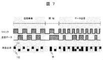
さらに、発明者は、スマートフォン等の端末の画面の輝度や処理速度にブレがあっても、安定して可視光通信が行えるように工夫した。図7は、可視光通信における端末13における送信信号のタイミングチャートを示す。送信信号としてクロックと送信データを示し、端末13の分割画面131、132の白黒は送信信号に応じて点滅する様子を示している。時間の経過(横軸)に沿って、送信準備期間(スタートトリガ)、送信開始合図、およびデータ送信、の期間が設定される。 Furthermore, the inventor devised so that visible light communication can be performed stably even if the brightness of the screen of a terminal such as a smart phone or the processing speed fluctuates. FIG. 7 shows a timing chart of transmission signals in the terminal 13 in visible light communication. A clock and transmission data are shown as a transmission signal, and black and white of the split screens 131 and 132 of the terminal 13 are shown blinking according to the transmission signal. A transmission preparation period (start trigger), a transmission start signal, and data transmission are set along the passage of time (horizontal axis).
図7のように、送信準備期間には、分割画面131、132の両方を用いて、端末13の画面制御部331が、クロックとその反転信号(反転クロック)の明暗パターンを送信するように制御する。これにより、分割画面131と分割画面132が交互に点滅を繰り返して、それに応じて、受信側のデバイス10の光素子261がクロックを受信し、光素子262が反転クロックを受信する。画面制御部331は、分割画面131と分割画面132が正しく交互に点滅する明暗パターンを基に、クロックおよび送信データの閾値を調整する。例えば、クロックおよび送信データの信号高さの中央値を閾値に設定する。 As shown in FIG. 7, during the transmission preparation period, both split
送信準備期間が経過した後の送信開始合図の期間には、画面制御部331が、反転クロックを送出していた分割画面132にクロックを印加すると、分割画面131と132が同じ明るさになる(図7のM)。その後、分割画面132を送信データ用に切り替える。受信側では、デバイス10の光素子制御部223が、光素子261と262が同じ明るさの信号(明状態)を検出して、その後光素子261が同じタイミングで暗状態を検出すると、データ送信開始合図であることを判断する。 During the transmission start signal period after the transmission preparation period has passed, the
上記期間の制御により端末の画面の輝度や処理速度に因るブレに対する調整が行われる。以後、画面制御部331は、クロック用の分割画面131を1/2またはそれ以下のタイミングに切り替えて点滅し、分割画面132を送信データの“1”“0”に応じて点滅して、それぞれ明暗パターンを送出する。受信側では、デバイス10の光素子261がクロックの明暗パターンを、光素子262が送信データの明暗パターンを、それぞれ受信する。なお、クロックのタイミングを1/2またはそれ以下に切り替えるのは送信速度を速めるためである。 By controlling the period described above, adjustment is made for blur caused by the brightness of the screen of the terminal and the processing speed. After that, the
<各管理テーブルおよびデータ形式について>
図8は、デバイス管理テーブルの構成を示す。
デバイス管理テーブル403は、デバイス10に固有なデバイスIDと、物品に固有な物品ID、およびフラグを対応付けて管理する。フラグは、デバイスIDと物品IDとの紐付けが済みか未済みを管理する。この紐付けの管理は、デバイス管理プログラム401の実行による。デバイスIDや物品IDは、システム側で管理されていればよく、必ずしもユーザが認識する必要がない。<Regarding each management table and data format>
FIG. 8 shows the configuration of the device management table.
The device management table 403 associates and manages a device ID unique to the
図9は、物品管理テーブルの構成を示す。
物品管理テーブル404は、全ての物品の物品名、物品ID、現在値、変更履歴を管理する。全ての物品とは、在庫管理の対象となる全ての物品であり、デバイスとの紐付けの有無を問わない。例えば、発注に基づいて納品されまたは新らに購入された物品の情報が、端末13からの入力により、物品管理テーブル404に逐次登録される。登録に際しては、物品管理部402が物品の登録ごとに物品IDを生成して付与する。現在値は現在の物品の数すなわち最新の更新値を表す。変更履歴は、対象の物品の数が更新される度にその前の現在値をログとして保持する。ログには更新された時間情報が付与される。
ユーザは、物品管理テーブル404の内容を端末13にダウンロードして表示部に表示し、物品の在庫状況を確認することができる。FIG. 9 shows the configuration of an article management table.
The article management table 404 manages article names, article IDs, current values, and change histories of all articles. All items are all items subject to inventory management, regardless of whether or not they are tied to a device. For example, information on goods delivered based on orders or newly purchased is sequentially registered in the goods management table 404 by input from the terminal 13 . At the time of registration, the
The user can download the content of the article management table 404 to the terminal 13 and display it on the display section to check the inventory status of the article.
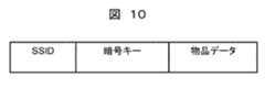
図10は、初期設定データの形式を示す。
端末13からデバイス10へ送信される初期設定データは、WifiのSSIDと、暗号キー(パスワード)と、物品データ(物品IDや個数)と、を有する形式である。なお、WifiのSSIDと暗号キーのみを送信する場合、または物品データのみを送信する場合もあり、この場合には他のデータを含まない。FIG. 10 shows the format of the initialization data.
The initial setting data transmitted from the terminal 13 to the
図11は、デバイスデータの形式を示す。
デバイスデータ、すなわちデバイス10から管理サーバ12へ送信されるデータは、物品IDと、更新前データと、更新後データと、を有する形式である。例えば、メモリ222に保持されている更新前のカウンタ値が「15」で、物品収納棚から当該物品が2つ取り出された場合、更新後のカウンタ値が「13」となり、デバイスデータには、更新前データ「15」と、更新後データ「13」が含まれる。FIG. 11 shows the format of device data.
Device data, that is, data transmitted from the
<端末13の画面表示例>
図13は、端末13の登録確認画面の表示例を示す図である。
デバイス10に登録する情報の確認画面が、端末13の表示部及び入力部を形成するタッチパネルの画面に表示される。登録確認画面には、デバイス10が利用するWifiの管理情報であるSSIDおよびパスワードを表示する表示エリア1301と、デバイス10が割当てられる物品ID、物品名およびその個数(物品データ)を表示する表示エリア1302と、これらの情報を登録指示する設定ボタン1303が含まれる。なお、物品IDは管理上のコードであるので必ずしも表示する必要がない。<Screen display example of
FIG. 13 is a diagram showing a display example of the registration confirmation screen of the terminal 13. As shown in FIG.
A screen for confirming information to be registered in the
この登録確認画面は、物品とデバイス10とを新たに紐付けて、そのデバイス10をWifiに接続するための管理情報を登録するために使用される。物品管理テーブル404には新たに納品された物品も含んで保管されているが、ユーザの選択により未だデバイス10が割り当てられていない物品(紐付け未完了物品)、すなわち、紐付け未完了物品の物品ID、物品名および個数が表示エリア1302に表示される。また、ユーザが、端末13の入力部31から入力するSSIDおよびパスワードが表示エリア1301に表示される。 This registration confirmation screen is used to newly associate an article with the
ユーザが、登録確認画面の表示内容を確認して、設定ボタン1303を押すと、可視光通信が開始されて、SSIDおよびパスワード、並びに物品IDとその個数が、可視光通信インタフェースを介して、端末13からデバイス10へ送信される。なお、物品の個数は後に管理サーバ12とデバイス10との間の通信により送信可能であるため、必ずしも最初に送信しなくてもよい。また、各デバイスに登録される物品名、個数は、管理サーバ12から取得しないで、端末13の入力部から入力されてもよい。 When the user confirms the display contents of the registration confirmation screen and presses the
<データ通信動作>
次に、図12を参照して、物品の在庫管理に伴う、デバイス10への管理情報の設定ないしデバイス10とのデータ通信の動作について説明する。
この動作に入る前提として、ユーザは、デバイスIDを有する未使用のデバイス10を所持している。用意されたデバイス10のメモリ222にはデバイスIDが予め格納されている。また、ユーザの周囲には、デバイス10との対応付けが成されていない物品がある。このような状況で、ユーザの端末13の操作により、物品とデバイス10との紐付けが行なわれる。<Data communication operation>
Next, referring to FIG. 12, the setting of management information in the
As a prerequisite for entering this operation, the user possesses an
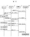
まず、ユーザが、端末13を操作して、管理サーバ12へ物品リストの取得要求を出す(S11)。これは、ユーザが手元に有するデバイス10とそのデバイス10が検知の対象とする物品を紐付けするための初期設定の動作である。取得要求を受けた管理サーバ12は、物品管理部402が物品管理テーブル404を参照して、全ての物品のデータ(物品リスト)を取得する(S12)。そして、取得要求の回答として物品リストを管理サーバ12から端末13へ送信する(S13)。端末13では、無線通信部35を介して物品リストを受信して、記憶部34に一時格納する。併せて、物品リストの内容が表示部32の画面に表示される。 First, the user operates the terminal 13 to issue an article list acquisition request to the management server 12 (S11). This is an initial setting operation for associating the
ユーザは、表示部32の画面に表示された物品リスト(すなわち在庫一覧)を見て、在庫状況を確認することができる。一態様では、この段階でユーザが表示画面に表示される「戻るキー」(不図示)を押下することで、終了することができる。一方、ユーザが、デバイスを用いて物品の在庫を管理したいと考える場合は、本実施例のように以下の動作に移る。 The user can check the inventory status by looking at the article list (that is, inventory list) displayed on the screen of the
次に、ユーザは、画面に表示された物品リストからデバイスと紐付けを行いたい物品をタップして選択する。例えば、表示部32の画面に物品管理テーブル404(図9)の内容が表示される場合、ユーザが、紐付け未完了物品である「Bn」「ボタン(白小)」を選択すると、制御部33の制御により表示部32の表示が切り替わって、図13に示すような登録確認画面が表示される。登録確認画面の表示エリア1302には、先ほど選択された物品ID、物品名および個数(物品データ)が表示される。さらに初期設定時に、ユーザは端末13の入力部31を操作して、デバイス10が利用するWifiのSSIDとパスワードを入力する。表示エリア1301にはこれらの管理情報が表示される。なお、物品名および数量を物品管理テーブル404から取得しないで、ユーザが入力部31から入力することも可能である。 Next, the user taps and selects an item to be associated with the device from the item list displayed on the screen. For example, when the contents of the item management table 404 (FIG. 9) are displayed on the screen of the
ユーザが、登録確認画面の内容を確認して問題がなければ、端末13から目的のデバイス10へ、WifiのSSIDとパスワード、および物品データを送信する準備ができた。そして、ユーザは、端末13の画面上に、デバイス10の光素子26のある面を対向させて配置し、設定ボタン1303を操作する。すると、端末13の画面制御部331が起動して、デバイス10へデータ登録要求を送信するための、端末13とデバイス10との間で可視光通信インタフェースによるデータ送信が行われる(図5乃至図7参照)(S14)。 If the user confirms the contents of the registration confirmation screen and there is no problem, the terminal 13 is ready to transmit the SSID and password of Wifi and the article data to the
画面制御部331により、SSIDとパスワード、および物品データが変調された明暗パターンが、デバイス10の光素子制御部223の制御の基で、光素子261,262により受信されて、CPU221により復調される。復調されたSSIDとパスワードおよび物品データがデバイス10のメモリ222に記憶されて、登録される(S15)。登録が終了すると、予めメモリ222に格納されていたデバイスIDが読み出されて、登録確認通知に付加されて、デバイス10から管理サーバ12へ送信される(S16)。管理サーバ12は登録確認通知を受信すると、デバイス管理部401が、受信されたデバイスIDを、デバイス管理テーブル403の物品IDに対応付けてフラグを「済」の状態にして、登録する(S17)。そして、登録完了通知を端末13へ送信する(S18)。 A light/dark pattern obtained by modulating the SSID, password, and article data by the
これで、1つの物品に係る初期設定の一連の動作は終わり、紐付けされたデバイス10と管理サーバ12との間で、Wifi18およびネットワーク19の接続が可能となった。なお、ユーザが、登録完了通知の表示画面に表示される「戻るボタン」(不表示)を操作すると、S14の処理に戻り、制御部33は物品リストの画面を再び表示する。そして上記の動作と同様に、ユーザに紐付け未完了物品の選択を促し、上記動作を繰り返すことができる。 With this, a series of operations for initial setting relating to one item is finished, and connection of
ここで、初期設定が失敗した場合、例えば端末13が一定時間内に登録完了の通知(S18)を受信できなかった時(例えばタイムアウトの発生)は、端末13の制御部33はデバイス10の初期設定が失敗したと判断して、初期設定失敗の旨を端末13の画面に表示する。ユーザは失敗の画面表示を見て初期設定の失敗を認識すると、ステップS11からの動作を繰り返すことになる。 Here, if the initial setting fails, for example, if the terminal 13 fails to receive the registration completion notification (S18) within a certain period of time (for example, timeout occurs), the
初期設定が成功した場合、運用時において、デバイス10の制御部22が、ユーザの操作によるカウンタボタン21の押下を検知すると(S21)、制御部22のCPU221は、管理サーバ12へ物品データの取得要求を送信する(S22)。物品データの取得要求は、デバイス10のメモリ222に保持しているカウンタの値が、物品管理テーブル404が記憶している現在値と一致するかを確認するためである。上記取得要求には物品IDが付加される。上記取得要求は、メモリ222に登録されたSSIDおよびパスワードにより設定されたWifi18およびネットワーク19を介して管理サーバ12へ送信される。 If the initial setting is successful, during operation, when the
管理サーバ12において、物品管理部402が物品管理テーブル404を検索して、その物品IDに対応する物品の現在値を取得する(S23)。そして、物品IDと共にその現在値を、要求があったデバイスIDを持つデバイス10へ送信する(S24)。 In the
デバイス10のCPU221は、物品IDおよび現在値を受信して、その現在値と、メモリ222に格納されているカウンタ値(更新前データ)と照合する(S25)。この照合は、カウンタボタン21の押下によるカウンタ値の更新前に、デバイス10が保持していたカウンタ値と管理サーバ12が管理する現在値(物品管理テーブル402が保持する現在値)との一致を確認するためである。照合の結果、不一致の場合は、管理サーバ12が管理する物品管理テーブル402の現在値をマスターとして、管理サーバ12から取得した現在値を、メモリ222内のカウンタ値に書き変える。 The
そして、CPU221は、ボタン212が押下された回数分をメモリ222が持つ最新のカウンタ値(更新前データ)から減算して、その更新値(更新後データ)をメモリ222に一時格納する(S26)。なお、ボタン211が押下されたときには加算された更新値となる。その後、CPU221は、更新前データと更新後データ(図11参照)に物品IDを付して、管理サーバ12へ物品データの更新要求を送信する(S27)。更新要求は、管理情報が設定されたWifi18およびネットワーク19を介して送信される。 Then, the
管理サーバ12がその更新要求を受信すると、物品管理部402は、受信した物品IDをキーにして、物品管理テーブル404を検索して、物品IDに対応する現在値を更新値に書き換える(S28,S29)。併せて、前の現在値に時間情報を付して変更履歴に保管する。上記処理S21~S29は、デバイス10のボタン21が押下される度に行われる。これにより、物品管理テーブル404は、物品IDごとに物品の最新の数を管理することができる。 When the
以上、データ通信動作の一例について説明したが、デバイスと物品との紐付けに際して、常に新規のデバイスを使用する必要はない。例えば、過去に使用されたデバイスと物品との対応付けが不要となった時、そのデバイスが他の新たな物品との紐付けのために使用されることがある。例えば、過去に使用されたデバイスID(例えばD0001)を新たな物品ID(例えばBn+1)を対応付けて登録することがある。この場合、上記S11~S18の動作が行われて、そのデバイスのメモリには、管理情報と新たな物品の物品データが登録されることになる。これは所謂、デバイスの使い回しであり、限られた数のデバイスを有効に利用することができる。 An example of the data communication operation has been described above, but it is not always necessary to use a new device when linking a device and an article. For example, when it is no longer necessary to associate a previously used device with an article, the device may be used for association with another new article. For example, a previously used device ID (eg, D0001) may be registered in association with a new article ID (eg, Bn+1). In this case, the operations of S11 to S18 are performed, and the management information and the product data of the new product are registered in the memory of the device. This is so-called device reuse, and a limited number of devices can be used effectively.
また、同じ物品に複数のデバイスを割り当てることが可能である。この場合、デバイス管理テーブル403には、同じ物品IDに対して複数のデバイスIDを対応付けて、複数のカラムに登録される。同じ物品に複数のデバイスを割り当てる利点としては、例えば、1のデバイスを物品が保管される倉庫の棚に配置し、他の1のデバイスを作業者の机上に置いてその物品の在庫状況のモニターとして使用する例がある。 It is also possible to assign multiple devices to the same item. In this case, in the device management table 403, multiple device IDs are associated with the same product ID and registered in multiple columns. The advantage of assigning multiple devices to the same item is that, for example, one device can be placed on a warehouse shelf where the item is stored, and another device can be placed on the worker's desk to monitor the inventory status of that item. There is an example of using it as
上記の処理により、選択された物品とデバイスとの紐付けが可能となり、デバイスを用いて物品の在庫を管理することができる。また、ユーザは、端末13から物品IDを指定して、または物品リストの取得要求を管理サーバ12へ送信して、個別の物品または全ての物品の最新の在庫データを取得して、端末13の画面に表示して確認することができる。 By the above processing, it becomes possible to link the selected article and the device, and the inventory of the article can be managed using the device. Also, the user can specify an item ID from the terminal 13 or transmit an item list acquisition request to the
実施例1における端末13とデバイス10間の通信は、図5、図11および図12に示すように、スマートフォンのような端末13の画面に、送信すべきデータを入力、表示して、端末13の画面上にデバイス10を搭載した状態で、端末13からデバイス10へデータを可視光通信している。 Communication between the terminal 13 and the
実施例2は、タブレット端末またはフラット型(180度開閉型)のノート型PC(パーソナルコンピュータ)等の端末13(説明の便宜上図3の符号を引用する)を用いて、1台の端末13から複数のデバイス10に対して同時に、可視光データ通信を可能とする。図14は、複数のデバイス10への可視光通信を行う端末の画面の例を示す。 In the second embodiment, a terminal 13 such as a tablet terminal or a flat type (180-degree open/close type) notebook PC (personal computer) (the reference numerals in FIG. 3 are used for convenience of explanation) is used, and from one
図示のように、端末13の登録確認画面は、入力されるWifiのSSIDおよびパスワードを表示する第1の表示エリア141と、複数(図示では3個)の各デバイスに対応する第2の表示エリア142を有している。デバイスごとの第2の表示エリア142はそれぞれ、データ登録の対象となるデバイス10に対する物品データ(物品ID、物品名、個数)を表示する欄1421と、データ登録先のデバイスを配置するデバイス配置表示欄1422を有する。デバイス配置表示欄1422は、デバイス10の受光素子側の面の大きさよりも若干大き目な四辺形がよい。ユーザが、データの可視光通信時に端末13の画面(詳しく言えば表示部261´および262´)の点滅を確認し易くするためである。表示欄142は左右で色分けされていて、デバイス10の光素子261が左側の表示部261´に、光素子262が右側の表示部262´に位置付けされるように配慮されている。端末13の画面制御部331は、各デバイス配置表示欄1422の表示部261´、262´を点滅制御して、各デバイス10に対して個別に可視光通信を行うことができる。 As shown in the figure, the registration confirmation screen of the terminal 13 has a
ユーザが端末13の入力部から入力したWifiのSSIDおよびパスワードは、第1の表示エリア141に表示される。3つのデバイスごとの第2の表示エリア142には、管理サーバ12から取得された物品データがそれぞれ表示される。なお、各デバイスに登録される物品名、個数は、管理サーバ12から取得しないで、端末13の入力部から入力されてもよい。ユーザは、第2の表示エリア142に表示された各デバイスに対する物品名、個数を確認し、必要な場合には入力部を操作して修正する。 The Wifi SSID and password that the user has entered from the input unit of the terminal 13 are displayed in the
ユーザは、第1および第2の表示エリア141、142に表示されたデータを確認した後、デバイス10を、対応するデバイス配置表示欄1422に並べる。そして、設定ボタン143を押下すると、表示部261´、262´がそれぞれ点滅して可視光通信が開始されて、各デバイス10へのデータ送信が順次行われる。その結果、SSIDおよびパスワード、並びにデバイスごとの物品名と個数のデータが、端末13から各デバイス10へ送信される。 After confirming the data displayed in the first and
なお、上記例では、SSIDおよびパスワード用の第1の表示エリア141と、複数のデバイス用の第2の表示エリア142を同じ画面に有しているが、他の例によれば、第1の表示エリア141と第2の表示エリア142をそれぞれ別の画面に設けてもよい。また、第2の表示エリア142に表示するデバイスの個数は適宜増減してよい。 In the above example, the
実施例2によれば、1台の端末の画面に複数のデバイスを配置することで、複数のデバイスへ一括してデータ通信を行って、必要なデータを各デバイスに登録することが可能となる。また、可視光通信に伴うタイミングや閾値の設定をデバイス個別に行う必要が無くなるので、デバイスへのデータ登録が効率化される。 According to the second embodiment, by arranging multiple devices on the screen of one terminal, it is possible to perform batch data communication with multiple devices and register necessary data in each device. . In addition, since there is no need to set the timing and threshold value associated with visible light communication for each device, the efficiency of data registration in the device is improved.
本発明は実施例1ないし2に限定されずに、いろいろと変形し或いは他に適用して実施し得る。以下、幾つかの他の例について説明する。 The present invention is not limited to
<管理サーバ12の例>
実施例1では、管理サーバ12はコンピュータであるが、他の例によれば、クラウドを利用して管理サーバ12の機能を実現することができる。すなわち、図4に示す機能の一部または全部をクラウドコンピュータに持たせ、或いはクラウドサービスにより実現することができる。例えば、ASP(アプリケーションサービスプロバイダ)やAPI(アプリケーションプログラミングインタフェース)を用いて、デバイス管理テーブル403や物品管理テーブル404、およびそれらの管理テーブルに対するデータの読み書きを行なうことができる。<Example of
In Example 1, the
<物品管理テーブルの例>
実施例1では、管理サーバ12が有する物品管理テーブル404は衣料品の原材料を管理する在庫管理テーブルである。他の例によれば、物品管理テーブルは、製作された衣料品、例えばワイシャツ、ズボン、ジャケット等の商品の在庫品を管理するテーブルであってもよい。<Example of article management table>
In
また、物品管理テーブルは、それ自体が単独で構成されるものでなくてもよい。例えば、SCM(サプライチェーンマネジメント)として、原材料から商品の生産および流通にわたる一連のプロセスが管理されるシステムの場合、そのSCMから原材料の在庫管理や商品の在庫管理のためのデータを選択して実施例1のように利用することも可能である。
また、物品管理テーブル404にデバイスIDの登録の欄を設けて、紐付けが完了したデバイスIDを物品IDに対応付けて登録してもよい。Also, the item management table itself does not have to be configured independently. For example, in the case of a system that manages a series of processes from raw materials to product production and distribution as SCM (supply chain management), data for raw material inventory management and product inventory management is selected from the SCM and implemented. It can also be used as in Example 1.
Alternatively, a device ID registration column may be provided in the item management table 404, and the device ID for which the linking has been completed may be registered in association with the item ID.
<物品IDの例>
実施例1では、物品IDを用いて物品を識別しているが、他の手段または用途に用いてもよい。例えば、デバイスが検知する対象または検知される物理量等のデータを識別する情報またはそれに関連付けられた情報、またはデバイスを識別するアドレス等の情報、またはデバイスが固有に持つまたは付与された情報、等を対象の識別情報として用いてもよい。この場合、上記物品管理テーブル404に代わって検知対象管理テーブル(例えば温度管理テーブル)と呼ばれるであろう。<Example of article ID>
Although the article ID is used to identify the article in the first embodiment, it may be used for other means or purposes. For example, information that identifies the object detected by the device or data such as the physical quantity that is detected or information associated with it, information such as the address that identifies the device, or information unique to or attached to the device, etc. You may use as identification information of object. In this case, instead of the article management table 404, it will be called a detection target management table (for example, a temperature management table).
<デバイス10の例1>
実施例1では、カウンタ10はボタン21の操作により計数値を入力するが、入力手段はボタンに限定されない。例えば、ボタン21に代えて音声マイクを備えて、この音声マイクから入力される音声を、制御部22が実行する音声認識プログラムの音声認識機能により、計数値のデータとして認識することができる。<Example 1 of
In Example 1, the
<デバイス10の例2>
実施例1では、デバイス10は在庫管理システムに適用される例における物品の数を検知するカウンタである。他の例によれば実施例1に限定されず、デバイス10は在庫管理以外にも適用可能である。例えば、デバイス10は、赤外線センサ、距離センサ、重量センサ、湿度センサ、温度センサ等の対象物の物理量や位置を検知するセンサにも適用可能である。この場合、実施例1のボタン21に代わって赤外線センサや温度センサ等が接続され、メモリ222にはセンサで検知された物理量等のデータが記憶される。また、実施例1における物品IDは、センサが検知する対象または物理量またはデバイスを識別する固有の識別IDとなり得る。制御部22は、センサで検知された物理量等のデータを固有の識別IDと共に、検知要求のあった管理サーバ等の外部装置へ送信する。<Example 2 of
In Example 1, the
<デバイス10の初期設定>
実施例1では、図10の形式で、デバイス10に管理情報および物品データの初期設定を行う、とした。他の例によれば、管理情報および物品データ以外にも種々の初期設定を行うことができる。<Initial setting of
In the first embodiment, initial setting of management information and article data is performed in the
例えば、デバイス10のボタンを押下後、一定時間経過すると省エネモード(スリープモード)機能を設ける場合、スリープまでの時間を初期設定することができる。
また他の例では電池残量の監視の設定がある。例えば、ボタン押下時に電池残量を管理サーバへ送信することで、電池残量を監視することができる。この場合、電池残量を管理サーバへ送信するかまたはデバイスでアラーム発生をさせるかの、初期設定を行うことができる。
また他の例では、ボタン操作音の音量の設定がある。例えばデバイス10にブザーを設けて、ボタンの長押し時にカウンタ値が高速にアップ又はダウンさせることできる。この場合、ブザーの音量を初期設定することができる。
なお、上記機能の初期設定は、実施例1における管理情報や物品データの初期設定時に必ずしも同時に行う必要がなく、その後必要時に適宜行ってよい。上記機能の初期設定も実施例1と同様に可視光通信を用いて行う。For example, when an energy-saving mode (sleep mode) function is provided after a certain period of time has elapsed after the button of the
Another example is the setting for monitoring remaining battery power. For example, the remaining battery level can be monitored by transmitting the remaining battery level to the management server when a button is pressed. In this case, an initial setting can be made as to whether the remaining battery level is to be transmitted to the management server or whether the device is to generate an alarm.
Another example is setting the volume of the button operation sound. For example, the
Note that the initial setting of the above functions does not necessarily have to be performed at the same time as the initial setting of the management information and article data in the first embodiment, and may be performed as appropriate thereafter. Initial setting of the above functions is also performed using visible light communication as in the first embodiment.
<端末13とデバイス10間の通信の例>
実施例1では、受光素子261がクロックを受信用、受光素子262をデータ受信用として、端末13の対応する分割画面が発する可視光を受光するとしたが、他の例ではこれに限定されない。例えば、1つの受光素子のみを持つデバイス10が、端末13の発光手段が発するデータ信号の可視光を受信する構成としてもよい。この場合、実施例1のような同期クロックを受信する受光素子は無いが、データを構成する1ビットのデータ時間幅およびデータ開始位置(所定のコードデータ)が予め分っていれば、デバイス10の処理部221は受光素子が受信する可視光の点滅(すなわち「1」「0」)およびその時間幅から1または0の連続から成るデータおよびデータ開始位置を認識することができる。<Example of communication between
In the first embodiment, the
また、他の例として、複数の受光素子を全てデータ受信用の素子としてもよい。この場合、複数の受光素子に対応して、端末13が有する複数の分割画面または複数の発光手段から複数のデータを多重で送信し、デバイス10の複数の受光素子が多重でデータを受信することができる。なお、例えば3つ以上の受光素子のうち1の受光素子を同期クロック受信用として使用してもよい。 As another example, all of the plurality of light receiving elements may be used as elements for data reception. In this case, a plurality of split screens or a plurality of light emitting means of the terminal 13 may transmit a plurality of data in a multiplexed manner corresponding to the plurality of light receiving elements, and the plurality of light receiving elements of the
また、他の例として、送信側の端末の分割画面を点滅させることに限らない。例えば、送信側装置が、受信側装置の1または複数の受光素子に対応する位置に、1または複数の発光素子(発光手段)を有し、送信データに応じてその発光素子を点滅させるように制御してよい。 In addition, as another example, it is not limited to blinking the split screen of the terminal on the transmission side. For example, the transmitting device has one or more light emitting elements (light emitting means) at positions corresponding to one or more light receiving elements of the receiving device, and blinks the light emitting elements according to the transmission data. You can control it.
<デバイス10と管理サーバ12間の通信インタフェースの例>
実施例1では、デバイス10と管理サーバ12間の無線通信インタフェースとしてWifiを用いているが、これに限定されず、例えば、ジグビー(ZigBee:登録商標)やLTE(Long Term Evolution)をもちいることができる。例えば、ジグビーは、多くのデバイスが接続可能であり、スリープ時の待機電力が小さく、また復帰時間も短いので、一定間隔を空けてデータ送信を行うような無線通信インタフェースとして有用である。このジグビーに係るアドレスや動作モード等の管理情報の設定に実施例1の手法が適用できる。
<Example of communication interface between
In
10:デバイス 12:管理サーバ 13:端末
18:Fifi 19:ネットワーク
21,211,212:ボタン 22:制御部 221:処理部
222:メモリ 223:光素子制御部
23:無線通信部 24:表示部 26,261,262:光素子
31:入力部 32:表示部 33:制御部
331:画面制御部 34:記憶部 35:無線通信部
40:記憶部 41:CPU 42入出力インタフェース
401:デバイス管理プログラム 402:物品管理プログラム
403:デバイス管理テーブル 404:物品管理テーブル
405:他の管理テーブル10: Device 12: Management Server 13: Terminal 18: Fifi 19: Network
21, 211, 212: button 22: control unit 221: processing unit 222: memory 223: optical element control unit 23: wireless communication unit 24:
Claims (8)
Translated fromJapanese前記第1の装置は、可視光を受光する受光素子を有し、
前記第2の装置は、表示部と、制御部とを有し、
前記第1の装置の前記受光素子と、前記第2の装置が有する前記表示部の表示画面を対応させるステップと、
前記制御部が、前記表示部の前記表示画面を点滅させて、データを可視光送信するステップと、
前記第1の装置の前記受光素子が、可視光送信された前記データを受信するステップと、
を有し、
前記表示部の表示画面は、入力部から入力されたデータまたは他の装置から取得されたデータを表示する第1の表示エリアと、前記第1の装置が配置される第2の表示エリアと、を有し、
前記制御部は、前記第2の表示エリアを点滅させて、前記第1の表示エリアに表示された前記データを可視光送信する、
ことを特徴とする通信方法。A method of communication between a first device and a second device, comprising:
The first device has a light receiving element that receives visible light,
The second device has a display unit and a control unit,
a step of associating the light-receiving element of the first device with the display screen of the display unit of the second device;
a step in which the control unit blinks the display screen of the display unit to transmit data with visible light;
a step in which the light receiving element of the first device receives the data transmitted by visible light;
has
The display screen of the display unit includes a first display area for displaying data input from an input unit or data acquired from another device, a second display area in which the first device is arranged, has
The control unit blinks the second display area and transmits visible light the data displayed in the first display area.
A communication method characterized by:
請求項1に記載の通信方法。The communication method according to claim1, wherein the first display area and the second display area are provided on the same display screen .
請求項1に記載の通信方法。The communication method according to claim1, wherein the first display area and the second display area are provided on separate display screens .
前記複数の表示エリア上に、複数の前記第1の装置を配置し、
前記制御部は、前記複数の表示エリアをそれぞれ点滅させて可視光送信する、
請求項1に記載の通信方法。the display unit of the second device displays a display screen having a plurality ofdisplay areas as the second display area ;
arranging a plurality of the first devices on the plurality of display areas;
The control unit transmits visible light by blinking the plurality ofdisplay areas , respectively.
The communication method according to claim1 .
前記第1の装置は、可視光を受光する受光素子を有し、
前記第2の装置は、表示部と、制御部とを有し、
前記第1の装置の前記受光素子と、前記第2の装置が有する前記表示部の表示画面を対応させた状態で、前記制御部が、前記表示部の前記表示画面を点滅させて、データを可視光送信し、
前記第1の装置の前記受光素子が、可視光送信された前記データを受信し、
前記第2の装置は、データが入力される入力部と、データを格納する記憶部とを有し、
前記表示部の表示画面は、入力部から入力されたデータまたは他の装置から取得されたデータを表示する第1の表示エリアと、前記第1の装置が配置される第2の表示エリアと、を有し、
前記制御部は、前記第2の表示エリアを点滅させて、前記第1の表示エリアに表示された前記データを可視光送信する、
ことを特徴とする通信システム。A communication system for communicating between a first device and a second device,
The first device has a light receiving element that receives visible light,
The second device has a display unit and a control unit,
In a state in which the light receiving element of the first device and the display screen of the display unit of the second device are associated with each other, the control unit flashes the display screen of the display unit to display data. transmit visible light,
the light receiving element of the first device receives the data transmitted by visible light;
The second device has an input unit for inputting data and a storage unit for storing data,
The display screen of the display unit includes a first display area for displaying data input from an input unit or data obtained from another device, a second display area in which the first device is arranged, has
The control unit blinks the second display area and transmits the data displayed in the first display area with visible light.
A communication system characterized by:
前記第1の装置は、可視光を受光する受光素子を有し、
前記第2の装置は、表示部と、制御部とを有し、
前記受光素子は、第1の受光素子と、第2の受光素子を有し、
前記表示部が、第1の分割画面と第2の分割画面を有する表示画面を表示し、
前記制御部が、前記第1の分割画面からクロックに対応する明暗パターンを送信し、前記第2の分割画面からデータに対応する明暗パターンを送信するように制御し、
前記第1の装置が、前記第1の受光素子が受信する前記クロックの前記明暗パターンに同期して、前記第2の受光素子が前記データの前記明暗パターンを受信する、
ことを特徴とする通信方法。A method of communication between a first device and a second device, comprising:
The first device has a light receiving element that receives visible light,
The second device has a display unit and a control unit,
The light receiving element has a first light receiving element and a second light receiving element,
the display unit displays a display screen having a first split screen and a second split screen;
the control unit controlsto transmit a light-dark pattern corresponding to a clock from the first split screen and to transmit a light-dark pattern corresponding to data from the second split screen;
wherein the first devicereceives the light-dark pattern of the data by the second light-receiving element in synchronization with the light-dark pattern of the clock received by the first light-receiving element;
A communication method characterized by:
前記第1の装置は、可視光を受光する複数の受光素子を有し、
前記第2の装置は、表示部と、制御部とを有し、
前記表示部が、複数の表示エリアを有する表示画面を表示するステップと、
前記制御部が、前記複数の各表示エリアを点滅させて、データを可視光送信するステップと、
前記第1の装置の前記複数の各受光素子が、前記複数の各表示エリアから可視光送信される前記データを受信するステップと、
を有することを特徴とする通信方法。A method of communication between a first device and a second device, comprising:
The first device has aplurality of light receiving elements that receive visible light,
The second device has a display unit and a control unit,
the display unit displaying a display screen having a plurality of display areas;
a step in which the control unit blinkseach of the plurality of display areas to transmit data with visible light;
each of the plurality of light receiving elements of the first device receiving the data transmitted by visible light fromeach of the plurality of display areas ;
A communication method characterized by comprising:
前記第1の装置は、可視光を受光する受光素子を有し、
前記第2の装置は、表示部と、制御部とを有し、
前記表示部が、複数の表示エリアを有する表示画面を表示するステップと、
複数の前記第1の装置と、前記複数の各表示エリアをそれぞれ対応させるステップと、
前記制御部が、前記複数の各表示エリアを点滅させて、データを可視光送信するステップと、
複数の前記第1の装置の前記受光素子が、対応する前記複数の各表示エリアから可視光送信された前記データを受信するステップと、
ことを特徴とする通信方法。A method of communication between a first device and a second device, comprising:
The first device has a light receiving element that receives visible light,
The second device has a display unit and a control unit,
the display unit displaying a display screen having a plurality of display areas;
associating each of the plurality of first devices witheach of the plurality of display areas ;
a step in which the control unit blinkseach of the plurality of display areas to transmit data with visible light;
a step in which the light-receiving elements of theplurality of first devices receive the data transmitted by visible lightfrom each of the corresponding plurality of display areas ;
A communication method characterized by:
Priority Applications (2)
| Application Number | Priority Date | Filing Date | Title |
|---|---|---|---|
| JP2022036640AJP7162285B1 (en) | 2021-05-31 | 2022-03-09 | Communication method and communication system |
| JP2022161689AJP2022185092A (en) | 2021-05-31 | 2022-10-06 | Data processing method and data processing system |
Applications Claiming Priority (2)
| Application Number | Priority Date | Filing Date | Title |
|---|---|---|---|
| JP2021091970AJP7043104B1 (en) | 2021-05-31 | 2021-05-31 | Device management system and its management method, article management system and its management method, and device and its communication method |
| JP2022036640AJP7162285B1 (en) | 2021-05-31 | 2022-03-09 | Communication method and communication system |
Related Parent Applications (1)
| Application Number | Title | Priority Date | Filing Date |
|---|---|---|---|
| JP2021091970ADivisionJP7043104B1 (en) | 2021-05-31 | 2021-05-31 | Device management system and its management method, article management system and its management method, and device and its communication method |
Related Child Applications (1)
| Application Number | Title | Priority Date | Filing Date |
|---|---|---|---|
| JP2022161689ADivisionJP2022185092A (en) | 2021-05-31 | 2022-10-06 | Data processing method and data processing system |
Publications (2)
| Publication Number | Publication Date |
|---|---|
| JP7162285B1true JP7162285B1 (en) | 2022-10-28 |
| JP2022184718A JP2022184718A (en) | 2022-12-13 |
Family
ID=87699499
Family Applications (2)
| Application Number | Title | Priority Date | Filing Date |
|---|---|---|---|
| JP2022036640AActiveJP7162285B1 (en) | 2021-05-31 | 2022-03-09 | Communication method and communication system |
| JP2022161689APendingJP2022185092A (en) | 2021-05-31 | 2022-10-06 | Data processing method and data processing system |
Family Applications After (1)
| Application Number | Title | Priority Date | Filing Date |
|---|---|---|---|
| JP2022161689APendingJP2022185092A (en) | 2021-05-31 | 2022-10-06 | Data processing method and data processing system |
Country Status (1)
| Country | Link |
|---|---|
| JP (2) | JP7162285B1 (en) |
Citations (4)
| Publication number | Priority date | Publication date | Assignee | Title |
|---|---|---|---|---|
| JP2010074420A (en) | 2008-09-17 | 2010-04-02 | Ricoh Co Ltd | Remote communication setting method of near-field wireless communication; connection support server device and program; and image forming device and program |
| US20140232903A1 (en) | 2012-12-27 | 2014-08-21 | Panasonic Corporation | Information communication method |
| JP2015149710A (en) | 2014-01-10 | 2015-08-20 | パナソニック インテレクチュアル プロパティ コーポレーション オブアメリカPanasonic Intellectual Property Corporation of America | Control method and program for portable terminal |
| WO2020169597A1 (en) | 2019-02-18 | 2020-08-27 | Worldline Sa | Electronic transaction |
- 2022
- 2022-03-09JPJP2022036640Apatent/JP7162285B1/enactiveActive
- 2022-10-06JPJP2022161689Apatent/JP2022185092A/enactivePending
Patent Citations (4)
| Publication number | Priority date | Publication date | Assignee | Title |
|---|---|---|---|---|
| JP2010074420A (en) | 2008-09-17 | 2010-04-02 | Ricoh Co Ltd | Remote communication setting method of near-field wireless communication; connection support server device and program; and image forming device and program |
| US20140232903A1 (en) | 2012-12-27 | 2014-08-21 | Panasonic Corporation | Information communication method |
| JP2015149710A (en) | 2014-01-10 | 2015-08-20 | パナソニック インテレクチュアル プロパティ コーポレーション オブアメリカPanasonic Intellectual Property Corporation of America | Control method and program for portable terminal |
| WO2020169597A1 (en) | 2019-02-18 | 2020-08-27 | Worldline Sa | Electronic transaction |
Also Published As
| Publication number | Publication date |
|---|---|
| JP2022184718A (en) | 2022-12-13 |
| JP2022185092A (en) | 2022-12-13 |
Similar Documents
| Publication | Publication Date | Title |
|---|---|---|
| KR20220091257A (en) | Method and system for inventory management using detachable to shelf inventory management device | |
| JP6136426B2 (en) | Clothing registration system, short-range wireless communication medium, portable communication terminal, clothing registration method and program | |
| JP2017126130A (en) | Customer service support system, customer service support server, and program | |
| JP2016162178A (en) | Article management device | |
| JP2018025972A (en) | Server, display terminal and program | |
| CN115481768B (en) | Equipment management system and management method thereof, article management system and management method thereof, and equipment and communication method thereof | |
| KR102008821B1 (en) | Refrigerator for managing food and system for managing food using this | |
| JP5748921B1 (en) | Goods management system | |
| JP2017126872A (en) | Wireless display system | |
| JP7162285B1 (en) | Communication method and communication system | |
| JP2016140368A (en) | Wireless display system | |
| JP5028319B2 (en) | Communication system and communication method | |
| KR20160030421A (en) | Electronic information label, server and stock management method using electronic information label | |
| JP2020202572A (en) | Wireless display system, mobile terminal device, and program for mobile terminal device | |
| US20160156701A1 (en) | Method for communicating information from radio frequency peripheral identifiers | |
| JP2024517140A (en) | Inventory control method and system with synchronized shelf systems and sensor activation - Patents.com | |
| TWM458742U (en) | Universal member card system using near field communication | |
| US20230028355A1 (en) | Controlling output of electronic labels from a camera | |
| KR20170091299A (en) | ESL integrated controller and operation method thereof | |
| JP2016219019A (en) | In-store location information management system | |
| CN112884528A (en) | Interactive processing method based on radio frequency identification and related device | |
| JP2011171993A (en) | Information processing apparatus, and radio terminal | |
| JP2013242901A (en) | Display terminal, screen processing device, and program | |
| KR20200052737A (en) | Cosmetics management system using cosmetics managing device | |
| JP2025005973A (en) | Product management system, appliance communication device, and product management method |
Legal Events
| Date | Code | Title | Description |
|---|---|---|---|
| A621 | Written request for application examination | Free format text:JAPANESE INTERMEDIATE CODE: A621 Effective date:20220408 | |
| A871 | Explanation of circumstances concerning accelerated examination | Free format text:JAPANESE INTERMEDIATE CODE: A871 Effective date:20220408 | |
| A131 | Notification of reasons for refusal | Free format text:JAPANESE INTERMEDIATE CODE: A131 Effective date:20220621 | |
| A521 | Request for written amendment filed | Free format text:JAPANESE INTERMEDIATE CODE: A523 Effective date:20220805 | |
| TRDD | Decision of grant or rejection written | ||
| A01 | Written decision to grant a patent or to grant a registration (utility model) | Free format text:JAPANESE INTERMEDIATE CODE: A01 Effective date:20220913 | |
| A61 | First payment of annual fees (during grant procedure) | Free format text:JAPANESE INTERMEDIATE CODE: A61 Effective date:20221006 | |
| R150 | Certificate of patent or registration of utility model | Ref document number:7162285 Country of ref document:JP Free format text:JAPANESE INTERMEDIATE CODE: R150 |