JP7159163B2 - Promotes pulmonary and systemic hemodynamics - Google Patents
Promotes pulmonary and systemic hemodynamicsDownload PDFInfo
- Publication number
- JP7159163B2 JP7159163B2JP2019533016AJP2019533016AJP7159163B2JP 7159163 B2JP7159163 B2JP 7159163B2JP 2019533016 AJP2019533016 AJP 2019533016AJP 2019533016 AJP2019533016 AJP 2019533016AJP 7159163 B2JP7159163 B2JP 7159163B2
- Authority
- JP
- Japan
- Prior art keywords
- subject
- pressure
- ppg sensor
- atrial
- pressure level
- Prior art date
- Legal status (The legal status is an assumption and is not a legal conclusion. Google has not performed a legal analysis and makes no representation as to the accuracy of the status listed.)
- Active
Links
- 230000000004hemodynamic effectEffects0.000titleclaimsdescription44
- 230000009885systemic effectEffects0.000titleclaimsdescription17
- 230000002685pulmonary effectEffects0.000titledescription10
- 210000004369bloodAnatomy0.000claimsdescription76
- 239000008280bloodSubstances0.000claimsdescription76
- 238000013186photoplethysmographyMethods0.000claimsdescription53
- 230000001746atrial effectEffects0.000claimsdescription49
- 230000036316preloadEffects0.000claimsdescription44
- 230000000747cardiac effectEffects0.000claimsdescription43
- 206010003658Atrial FibrillationDiseases0.000claimsdescription40
- 230000004088pulmonary circulationEffects0.000claimsdescription38
- 238000000034methodMethods0.000claimsdescription32
- 230000007704transitionEffects0.000claimsdescription31
- 230000000241respiratory effectEffects0.000claimsdescription28
- 230000004044responseEffects0.000claimsdescription26
- 230000001839systemic circulationEffects0.000claimsdescription23
- 238000009825accumulationMethods0.000claimsdescription21
- 238000009423ventilationMethods0.000claimsdescription20
- 210000003462veinAnatomy0.000claimsdescription18
- 210000005245right atriumAnatomy0.000claimsdescription16
- 230000003519ventilatory effectEffects0.000claimsdescription16
- 210000005246left atriumAnatomy0.000claimsdescription15
- 230000003205diastolic effectEffects0.000claimsdescription14
- 238000012544monitoring processMethods0.000claimsdescription14
- 210000003492pulmonary veinAnatomy0.000claimsdescription13
- 230000010355oscillationEffects0.000claimsdescription9
- 208000002102Atrial Premature ComplexesDiseases0.000claimsdescription6
- 230000001419dependent effectEffects0.000claimsdescription4
- 230000000694effectsEffects0.000claimsdescription4
- 210000001061foreheadAnatomy0.000claimsdescription4
- 230000010349pulsationEffects0.000claimsdescription4
- 206010020919HypervolaemiaDiseases0.000claimsdescription3
- 230000004087circulationEffects0.000claimsdescription3
- 238000001514detection methodMethods0.000claimsdescription2
- 206010042602Supraventricular extrasystolesDiseases0.000claims2
- 230000003213activating effectEffects0.000claims1
- 239000007789gasSubstances0.000description64
- 238000002560therapeutic procedureMethods0.000description37
- 230000029058respiratory gaseous exchangeEffects0.000description29
- 210000001147pulmonary arteryAnatomy0.000description21
- 206010016803Fluid overloadDiseases0.000description13
- 230000002861ventricularEffects0.000description12
- 230000000875corresponding effectEffects0.000description11
- 210000002837heart atriumAnatomy0.000description11
- 230000017531blood circulationEffects0.000description10
- 238000012545processingMethods0.000description10
- 230000008859changeEffects0.000description9
- 230000001276controlling effectEffects0.000description9
- 210000003205muscleAnatomy0.000description9
- 210000001367arteryAnatomy0.000description8
- 230000000670limiting effectEffects0.000description8
- 238000004891communicationMethods0.000description7
- 230000033001locomotionEffects0.000description7
- 230000003387muscularEffects0.000description7
- 230000033228biological regulationEffects0.000description6
- 210000005241right ventricleAnatomy0.000description6
- 230000001225therapeutic effectEffects0.000description6
- 230000002792vascularEffects0.000description6
- 230000006870functionEffects0.000description5
- 230000003434inspiratory effectEffects0.000description5
- 239000000203mixtureSubstances0.000description5
- 230000036387respiratory rateEffects0.000description5
- 230000035882stressEffects0.000description5
- 230000036772blood pressureEffects0.000description4
- 238000004590computer programMethods0.000description4
- 230000007423decreaseEffects0.000description4
- 210000004072lungAnatomy0.000description4
- 230000003287optical effectEffects0.000description4
- 230000001737promoting effectEffects0.000description4
- 230000001105regulatory effectEffects0.000description4
- 230000004913activationEffects0.000description3
- 206010003119arrhythmiaDiseases0.000description3
- 230000004872arterial blood pressureEffects0.000description3
- 210000000038chestAnatomy0.000description3
- 230000010339dilationEffects0.000description3
- 210000005240left ventricleAnatomy0.000description3
- 238000004519manufacturing processMethods0.000description3
- 208000001797obstructive sleep apneaDiseases0.000description3
- 230000010412perfusionEffects0.000description3
- 230000008569processEffects0.000description3
- 108020003175receptorsProteins0.000description3
- 210000003019respiratory muscleAnatomy0.000description3
- 206010007559Cardiac failure congestiveDiseases0.000description2
- 206010015856ExtrasystolesDiseases0.000description2
- 206010019280Heart failuresDiseases0.000description2
- 208000000418Premature Cardiac ComplexesDiseases0.000description2
- 230000001133accelerationEffects0.000description2
- 210000002565arterioleAnatomy0.000description2
- 238000010009beatingMethods0.000description2
- 230000006399behaviorEffects0.000description2
- 206010061592cardiac fibrillationDiseases0.000description2
- 230000003247decreasing effectEffects0.000description2
- 210000005069earsAnatomy0.000description2
- 238000005516engineering processMethods0.000description2
- 230000002600fibrillogenic effectEffects0.000description2
- 239000012530fluidSubstances0.000description2
- 210000004731jugular veinAnatomy0.000description2
- 230000007246mechanismEffects0.000description2
- 210000000412mechanoreceptorAnatomy0.000description2
- 108091008709muscle spindlesProteins0.000description2
- 230000001314paroxysmal effectEffects0.000description2
- 210000003102pulmonary valveAnatomy0.000description2
- 230000009467reductionEffects0.000description2
- 210000000115thoracic cavityAnatomy0.000description2
- 238000002604ultrasonographyMethods0.000description2
- 206010006440Bronchial obstructionDiseases0.000description1
- 241001631457CannulaSpecies0.000description1
- 208000006029CardiomegalyDiseases0.000description1
- 206010008469Chest discomfortDiseases0.000description1
- 206010067171RegurgitationDiseases0.000description1
- 206010038687Respiratory distressDiseases0.000description1
- 230000009471actionEffects0.000description1
- 238000004458analytical methodMethods0.000description1
- 210000003484anatomyAnatomy0.000description1
- 230000006793arrhythmiaEffects0.000description1
- 208000006673asthmaDiseases0.000description1
- 230000008901benefitEffects0.000description1
- 230000002146bilateral effectEffects0.000description1
- 230000000903blocking effectEffects0.000description1
- 210000005242cardiac chamberAnatomy0.000description1
- 230000001684chronic effectEffects0.000description1
- 239000000470constituentSubstances0.000description1
- 238000010276constructionMethods0.000description1
- 238000011513continuous positive airway pressure therapyMethods0.000description1
- 230000008602contractionEffects0.000description1
- 230000002596correlated effectEffects0.000description1
- 230000003111delayed effectEffects0.000description1
- 238000010586diagramMethods0.000description1
- 238000002567electromyographyMethods0.000description1
- 230000004217heart functionEffects0.000description1
- 238000003384imaging methodMethods0.000description1
- 230000010365information processingEffects0.000description1
- 230000007774longtermEffects0.000description1
- 230000004048modificationEffects0.000description1
- 238000012986modificationMethods0.000description1
- 230000000414obstructive effectEffects0.000description1
- 230000003534oscillatory effectEffects0.000description1
- 230000036961partial effectEffects0.000description1
- 230000037361pathwayEffects0.000description1
- 230000002085persistent effectEffects0.000description1
- 230000004962physiological conditionEffects0.000description1
- 230000035790physiological processes and functionsEffects0.000description1
- 230000002265preventionEffects0.000description1
- 230000000541pulsatile effectEffects0.000description1
- 230000035485pulse pressureEffects0.000description1
- 230000002829reductive effectEffects0.000description1
- 238000010992refluxMethods0.000description1
- 238000007634remodelingMethods0.000description1
- 230000036391respiratory frequencyEffects0.000description1
- 210000002345respiratory systemAnatomy0.000description1
- 238000002644respiratory therapyMethods0.000description1
- 230000000284resting effectEffects0.000description1
- 230000033764rhythmic processEffects0.000description1
- 201000002859sleep apneaDiseases0.000description1
- 238000004611spectroscopical analysisMethods0.000description1
- 230000002459sustained effectEffects0.000description1
- 208000024891symptomDiseases0.000description1
Images


Classifications
- G—PHYSICS
- G16—INFORMATION AND COMMUNICATION TECHNOLOGY [ICT] SPECIALLY ADAPTED FOR SPECIFIC APPLICATION FIELDS
- G16H—HEALTHCARE INFORMATICS, i.e. INFORMATION AND COMMUNICATION TECHNOLOGY [ICT] SPECIALLY ADAPTED FOR THE HANDLING OR PROCESSING OF MEDICAL OR HEALTHCARE DATA
- G16H20/00—ICT specially adapted for therapies or health-improving plans, e.g. for handling prescriptions, for steering therapy or for monitoring patient compliance
- G16H20/40—ICT specially adapted for therapies or health-improving plans, e.g. for handling prescriptions, for steering therapy or for monitoring patient compliance relating to mechanical, radiation or invasive therapies, e.g. surgery, laser therapy, dialysis or acupuncture
- G—PHYSICS
- G16—INFORMATION AND COMMUNICATION TECHNOLOGY [ICT] SPECIALLY ADAPTED FOR SPECIFIC APPLICATION FIELDS
- G16H—HEALTHCARE INFORMATICS, i.e. INFORMATION AND COMMUNICATION TECHNOLOGY [ICT] SPECIALLY ADAPTED FOR THE HANDLING OR PROCESSING OF MEDICAL OR HEALTHCARE DATA
- G16H20/00—ICT specially adapted for therapies or health-improving plans, e.g. for handling prescriptions, for steering therapy or for monitoring patient compliance
- G16H20/30—ICT specially adapted for therapies or health-improving plans, e.g. for handling prescriptions, for steering therapy or for monitoring patient compliance relating to physical therapies or activities, e.g. physiotherapy, acupressure or exercising
- A—HUMAN NECESSITIES
- A61—MEDICAL OR VETERINARY SCIENCE; HYGIENE
- A61B—DIAGNOSIS; SURGERY; IDENTIFICATION
- A61B5/00—Measuring for diagnostic purposes; Identification of persons
- A61B5/0059—Measuring for diagnostic purposes; Identification of persons using light, e.g. diagnosis by transillumination, diascopy, fluorescence
- A61B5/0082—Measuring for diagnostic purposes; Identification of persons using light, e.g. diagnosis by transillumination, diascopy, fluorescence adapted for particular medical purposes
- A—HUMAN NECESSITIES
- A61—MEDICAL OR VETERINARY SCIENCE; HYGIENE
- A61B—DIAGNOSIS; SURGERY; IDENTIFICATION
- A61B5/00—Measuring for diagnostic purposes; Identification of persons
- A61B5/02—Detecting, measuring or recording for evaluating the cardiovascular system, e.g. pulse, heart rate, blood pressure or blood flow
- A61B5/026—Measuring blood flow
- A61B5/0295—Measuring blood flow using plethysmography, i.e. measuring the variations in the volume of a body part as modified by the circulation of blood therethrough, e.g. impedance plethysmography
- A—HUMAN NECESSITIES
- A61—MEDICAL OR VETERINARY SCIENCE; HYGIENE
- A61M—DEVICES FOR INTRODUCING MEDIA INTO, OR ONTO, THE BODY; DEVICES FOR TRANSDUCING BODY MEDIA OR FOR TAKING MEDIA FROM THE BODY; DEVICES FOR PRODUCING OR ENDING SLEEP OR STUPOR
- A61M16/00—Devices for influencing the respiratory system of patients by gas treatment, e.g. ventilators; Tracheal tubes
- A61M16/021—Devices for influencing the respiratory system of patients by gas treatment, e.g. ventilators; Tracheal tubes operated by electrical means
- A61M16/022—Control means therefor
- A61M16/024—Control means therefor including calculation means, e.g. using a processor
- G—PHYSICS
- G16—INFORMATION AND COMMUNICATION TECHNOLOGY [ICT] SPECIALLY ADAPTED FOR SPECIFIC APPLICATION FIELDS
- G16H—HEALTHCARE INFORMATICS, i.e. INFORMATION AND COMMUNICATION TECHNOLOGY [ICT] SPECIALLY ADAPTED FOR THE HANDLING OR PROCESSING OF MEDICAL OR HEALTHCARE DATA
- G16H40/00—ICT specially adapted for the management or administration of healthcare resources or facilities; ICT specially adapted for the management or operation of medical equipment or devices
- G16H40/60—ICT specially adapted for the management or administration of healthcare resources or facilities; ICT specially adapted for the management or operation of medical equipment or devices for the operation of medical equipment or devices
- G16H40/63—ICT specially adapted for the management or administration of healthcare resources or facilities; ICT specially adapted for the management or operation of medical equipment or devices for the operation of medical equipment or devices for local operation
- G—PHYSICS
- G16—INFORMATION AND COMMUNICATION TECHNOLOGY [ICT] SPECIALLY ADAPTED FOR SPECIFIC APPLICATION FIELDS
- G16H—HEALTHCARE INFORMATICS, i.e. INFORMATION AND COMMUNICATION TECHNOLOGY [ICT] SPECIALLY ADAPTED FOR THE HANDLING OR PROCESSING OF MEDICAL OR HEALTHCARE DATA
- G16H50/00—ICT specially adapted for medical diagnosis, medical simulation or medical data mining; ICT specially adapted for detecting, monitoring or modelling epidemics or pandemics
- G16H50/70—ICT specially adapted for medical diagnosis, medical simulation or medical data mining; ICT specially adapted for detecting, monitoring or modelling epidemics or pandemics for mining of medical data, e.g. analysing previous cases of other patients
- A—HUMAN NECESSITIES
- A61—MEDICAL OR VETERINARY SCIENCE; HYGIENE
- A61M—DEVICES FOR INTRODUCING MEDIA INTO, OR ONTO, THE BODY; DEVICES FOR TRANSDUCING BODY MEDIA OR FOR TAKING MEDIA FROM THE BODY; DEVICES FOR PRODUCING OR ENDING SLEEP OR STUPOR
- A61M16/00—Devices for influencing the respiratory system of patients by gas treatment, e.g. ventilators; Tracheal tubes
- A61M16/0003—Accessories therefor, e.g. sensors, vibrators, negative pressure
Landscapes
- Health & Medical Sciences (AREA)
- Engineering & Computer Science (AREA)
- Life Sciences & Earth Sciences (AREA)
- Public Health (AREA)
- General Health & Medical Sciences (AREA)
- Medical Informatics (AREA)
- Biomedical Technology (AREA)
- Epidemiology (AREA)
- Primary Health Care (AREA)
- Heart & Thoracic Surgery (AREA)
- Animal Behavior & Ethology (AREA)
- Biophysics (AREA)
- Veterinary Medicine (AREA)
- Surgery (AREA)
- Pathology (AREA)
- Molecular Biology (AREA)
- Physics & Mathematics (AREA)
- Hematology (AREA)
- Data Mining & Analysis (AREA)
- Anesthesiology (AREA)
- Pulmonology (AREA)
- Emergency Medicine (AREA)
- Cardiology (AREA)
- Physiology (AREA)
- Physical Education & Sports Medicine (AREA)
- Business, Economics & Management (AREA)
- Databases & Information Systems (AREA)
- General Business, Economics & Management (AREA)
- Nuclear Medicine, Radiotherapy & Molecular Imaging (AREA)
- Urology & Nephrology (AREA)
- Measurement Of The Respiration, Hearing Ability, Form, And Blood Characteristics Of Living Organisms (AREA)
- Measuring Pulse, Heart Rate, Blood Pressure Or Blood Flow (AREA)
- Medical Treatment And Welfare Office Work (AREA)
Description
Translated fromJapanese関連出願の相互参照
[01] 本特許出願は、米国特許法119条(e)の定めにより、2016年12月20日に出願された米国仮特許出願第62/436,465号の優先権の利益を主張するものであり、その内容は、参照により本明細書に組み込まれる。Cross-reference to related applications
[01] This patent application claims the benefit of priority under 35 U.S.C. and the contents of which are incorporated herein by reference.
[02] 本開示は、前負荷の変化によって引き起こされる心不整脈又は心臓の構造的変化の治療及び/又は防止において、肺及び全身の血行動態を監視及び促進するためのシステム及び方法に関する。 [02] The present disclosure relates to systems and methods for monitoring and promoting pulmonary and systemic hemodynamics in the treatment and/or prevention of cardiac arrhythmias or structural changes in the heart caused by changes in preload.
[03] 圧力支援呼吸治療システムが知られている。典型的には、圧力支援治療システムパラメータ(例えば、圧力レベル、ボリューム、速度など)は、対象者が適切な気流を確実に受け取るように構成される。圧力支援治療システムは、典型的には、対象者における血行動態を監視し、及び/又はそれに影響を与えるようには構成されない。 [03] Pressure assisted respiratory therapy systems are known. Typically, pressure support therapy system parameters (eg, pressure level, volume, velocity, etc.) are configured to ensure that the subject receives adequate airflow. Pressure support therapy systems are typically not configured to monitor and/or affect hemodynamics in a subject.
[04] 故に、本開示の1つ又は複数の態様は、心房前負荷における変化を監視する感知システム、及び対象者における肺及び全身循環を促進するように構成された換気支援システムに関する。システムは、圧力生成器、第1及び第2のセンサ、1つ又は複数のハードウェアプロセッサ、及び/又は他のコンポーネントを備える。圧力生成器は、圧力支援治療レジームに従った対象者の気道への送達のための呼吸可能ガスの圧流を生成するように構成される。圧力支援治療レジームは、対象者による吸息及び呼息の期間中に圧力生成器によって提供される呼吸可能ガスの圧流の圧力レベルを示す。第1のセンサは、対象者における心臓周期及び呼吸周期の期間中の静脈血液蓄積に関する情報を搬送する出力信号を生成するように構成される。第2のセンサは、対象者における心房血液ボリューム過負荷及び心臓前負荷及び後負荷における変化に関する情報を搬送する出力信号を生成するように構成される。前負荷は、心房における拡張終期の圧力である。所与の適合性によって、これは、心房における拡張終期の血液ボリュームでもあり得る。従って、前負荷の変化は、圧力の変化及び血液ボリュームの変化の両方である。本明細書において説明されるように、本システムは、ボリュームにおける変化を測定するものであり、つまり、本システムは、前負荷及び前負荷の変化を、ボリュームを中心として見るものである。同じことが後負荷に関しても言える。これは、収縮終期の圧力及び/又は血液ボリュームの両方である。このようなボリュームによる見方においては、後負荷の変化は、1回拍出量における変化に対応する流出血液ボリュームの変化である。1つ又は複数のハードウェアプロセッサは、第1のセンサ及び第2のセンサからの出力信号に基づいて、肺及び全身循環を促進するために吸息及び呼息のうちの一方又は両方の期間中に呼吸可能ガスの圧流の圧力レベルを調節するように圧力生成器を制御するように、機械可読命令によって構成される。 [04] Accordingly, one or more aspects of the present disclosure relate to a sensing system for monitoring changes in atrial preload and a ventilatory support system configured to promote pulmonary and systemic circulation in a subject. The system comprises a pressure generator, first and second sensors, one or more hardware processors, and/or other components. The pressure generator is configured to generate a pressurized flow of breathable gas for delivery to the subject's airway according to a pressure support treatment regime. The pressure support treatment regime indicates the pressure level of the pressurized flow of breathable gas provided by the pressure generator during inspiration and expiration by the subject. The first sensor is configured to generate an output signal that conveys information about venous blood accumulation during cardiac and respiratory cycles in the subject. The second sensor is configured to generate an output signal that conveys information regarding changes in atrial blood volume overload and cardiac preload and afterload in the subject. Preload is the end-diastolic pressure in the atria. With a given fit, this could also be the end-diastolic blood volume in the atria. Therefore, preload changes are both pressure changes and blood volume changes. As described herein, the system measures changes in volume, ie, the system looks at preload and changes in preload centered on volume. The same is true for the afterload. This is both end-systolic pressure and/or blood volume. In this volumetric view, changes in afterload are changes in outflow blood volume that correspond to changes in stroke volume. One or more hardware processors, based on the output signals from the first sensor and the second sensor, during one or both of inspiration and expiration to promote pulmonary and systemic circulation. machine readable instructions to control the pressure generator to regulate the pressure level of the pressurized flow of breathable gas.
[05] 本開示の別の態様は、換気支援システムによって、対象者における肺及び全身循環を促進するための換気支援方法に関する。システムは、圧力生成器、第1のセンサ、第2のセンサ、1つ又は複数のハードウェアプロセッサ、及び/又は他のコンポーネントを備える。方法は、圧力生成器によって、圧力支援治療レジームに従った対象者の気道への送達のための呼吸可能ガスの圧流を生成するステップを有する。圧力支援治療レジームは、対象者による吸息及び呼息の期間中に圧力生成器によって提供される呼吸可能ガスの圧流の圧力レベルを示す。方法は、第1のセンサによって、対象者における心臓周期及び呼吸周期の期間中の静脈血液蓄積に関する情報を搬送する出力信号を生成するステップと、第2のセンサによって、対象者における心房血液ボリューム及び心臓前負荷/後負荷に関する情報を搬送する出力信号を生成するステップと、1つ又は複数のハードウェアプロセッサによって、第1のセンサ及び第2のセンサからの出力信号に基づいて、肺及び全身循環を促進するために吸息及び呼息のうちの一方又は両方の期間中に呼吸可能ガスの圧流の圧力レベルを調節するように圧力生成器を制御するステップと、を更に有する。 [05] Another aspect of the present disclosure relates to a ventilatory support method for promoting pulmonary and systemic circulation in a subject with a ventilatory support system. A system comprises a pressure generator, a first sensor, a second sensor, one or more hardware processors, and/or other components. The method includes generating, with a pressure generator, a pressurized flow of breathable gas for delivery to the subject's airway according to a pressure support treatment regime. The pressure support treatment regime indicates the pressure level of the pressurized flow of breathable gas provided by the pressure generator during inspiration and expiration by the subject. The method comprises the steps of generating, with a first sensor, an output signal conveying information about venous blood accumulation during cardiac and respiratory cycles in the subject; generating output signals conveying information about cardiac preload/afterload; controlling the pressure generator to adjust the pressure level of the pressurized flow of breathable gas during one or both of inspiration and expiration to promote breathing.
[06] 本開示のなおも別の態様は、対象者における肺及び全身循環を促進するように構成されたシステムに関する。システムは、圧力支援治療レジームに従った対象者の気道への送達のための呼吸可能ガスの圧流を生成するための手段であって、圧力支援治療レジームは、対象者による吸息及び呼息の期間中に圧力生成器によって提供される呼吸可能ガスの圧流の圧力レベルを示す、手段と、対象者における心臓周期の期間中の静脈血液蓄積に関する情報を搬送する出力信号を生成する手段と、対象者における血液ボリューム、心臓前負荷及び血液ボリューム、並びに前負荷変化に関する情報を搬送する出力信号を生成する手段と、静脈血液蓄積に関する情報を搬送する出力信号を生成する手段、及び血液ボリューム、心臓前負荷及び血液ボリューム、並びに前負荷変化に関する情報を搬送する出力信号を生成する手段からの出力信号に基づいて、肺及び全身循環を促進するために吸息及び呼息のうちの一方又は両方の期間中に呼吸可能ガスの圧流の圧力レベルを調節するように呼吸可能ガスの圧流を生成するための手段を制御するための手段と、を備える。 [06] Yet another aspect of the present disclosure relates to a system configured to promote pulmonary and systemic circulation in a subject. The system is means for generating a pressurized flow of breathable gas for delivery to an airway of a subject according to a pressure support treatment regime, the pressure support treatment regime being defined by the subject's inhalation and exhalation. means for indicating the pressure level of the pressure flow of breathable gas provided by the pressure generator during the period; means for generating an output signal conveying information about venous blood accumulation during a cardiac cycle in the subject; Means for generating an output signal conveying information about blood volume, cardiac preload and blood volume, and preload changes in a subject; periods of one or both of inspiration and expiration to promote pulmonary and systemic circulation based on output signals from the means for producing output signals conveying information about load and blood volume and preload changes; means for controlling the means for generating the pressurized flow of breathable gas to adjust the pressure level of the pressurized flow of breathable gas therein.
[07] 本開示のこれらの及び他の特徴及び特性、並びに、構造の関連する要素の動作の方法及び機能、部分の組み合わせ及び製造の経済性は、添付の図面を参照して以下の説明及び添付の特許請求の範囲を検討することで、より明らかになるであろう。図面はその全てが本明細書の一部を形成し、類似の参照番号は様々な図において対応する部分を指す。しかしながら、図面は、例示及び説明のみを目的とするものであり、本開示の限定の定義として意図されるものでないことを、明確に理解されたい。 [07] These and other features and characteristics of the present disclosure, as well as the methods and functions of operation of relevant elements of construction, combinations of parts and economies of manufacture, are described in the following description and with reference to the accompanying drawings. It will become clearer from a study of the appended claims. The drawings all form part of the present specification and like reference numerals refer to corresponding parts in the various figures. It is expressly understood, however, that the drawings are for the purpose of illustration and description only and are not intended as a definition of the limits of the disclosure.
[19] 本明細書において使用されるとき、コンテキストが明確にそうでないことを示すのでない限り、単数形の「1つの(a)」、「1つの(an)」及び「その(the)」は、複数の参照先を含む。本明細書において使用されるとき、2つ以上の部分又はコンポーネントが「結合される」という記述は、これらの部分が、直接的に、又は間接的に、すなわち、リンクが生じる限りにおいて1つ又は複数の中間的な部分又はコンポーネントを介して、一緒に接合され又は動作することを意味する。本明細書において使用されるとき、「直接的に結合される」とは、2つの要素が互いに対して直接的に接触していることを意味する。本明細書において使用されるとき、「固定的に結合される」又は「固定される」とは、2つのコンポーネントが、互いに対して一定の向きを維持しつつ、一体的に移動するように結合されることを意味する。本明細書において使用されるとき、「取り外し可能に結合される」とは、2つの要素が、互いから分離され得、及び/又は互いに対して再接合され得ることを意味する。 [19] As used herein, unless the context clearly indicates otherwise, the singular forms "a", "an" and "the" contains multiple references. As used herein, a statement that two or more parts or components are "coupled" means that those parts are directly or indirectly i.e., to the extent that a link occurs, one or It means joined or operating together through a plurality of intermediate parts or components. As used herein, "directly coupled" means that two elements are in direct contact with each other. As used herein, "fixedly coupled" or "fixed" means that two components are coupled such that they move together while maintaining a constant orientation with respect to each other. means to be As used herein, "removably coupled" means that two elements can be separated from each other and/or rejoined to each other.
[20] 本明細書において使用されるとき、「単体の」という語は、コンポーネントが、単一の部品又はユニットとして作成されていることを意味する。すなわち、別個に作成され、次いでユニットとして結合された複数の部品を含むコンポーネントは、「単体の」コンポーネント又は物体ではない。本明細書において用いられるとき、2つ以上の部分又はコンポーネントが互いに「係合する」という記述は、これらの部分が、直接的に、又は1つ又は複数の中間的な部分又はコンポーネントを介して、互いに対して力を作用させることを意味する。本明細書において用いられるとき、「数」という用語は、1又は1より大きい整数(すなわち、複数)を意味する。 [20] As used herein, the term "unitary" means that a component is made as a single piece or unit. That is, a component that includes multiple parts made separately and then combined as a unit is not a "single" component or object. As used herein, a statement that two or more parts or components "engage" each other means that those parts either directly or through one or more intermediate parts or components , means exerting a force on each other. As used herein, the term "number" means 1 or an integer greater than 1 (ie, a plurality).
[21] 本明細書において使用される方向性を示す語句、例えば、これらに限定されるものではないが、上部、底部、左、右、上側、下側、前、後など及びこれらの派生語は、図面において図示される要素の向きに関し、明示的に述べられない限り、特許請求の範囲を限定するものではない。 [21] Directional phrases used herein, such as, but not limited to, top, bottom, left, right, top, bottom, front, rear, etc. and derivatives thereof do not limit the scope of the claims unless explicitly stated with respect to the orientation of elements depicted in the drawings.
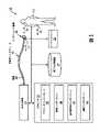
[22] 図1は、対象者12における肺及び全身循環を促進するように構成された換気支援システム10の概略的な図である。システム10は、肺の血行動態の平衡をとるように心臓を援助し、心臓過負荷(心房の過剰な伸展及び/又は膨張を含む)を阻止及び/又は反転させ、心臓の構造的変化の発病及び心房細動を阻止及び/又は防止し、及び/又は他の動作を行うように構成される。発作性心房細動(Afib)は、睡眠時無呼吸に悩まされている対象者において、より多く見られる。これらの対象者は、しばしば、睡眠中に発作性Afibの発症を経験する。閉塞性睡眠時無呼吸(OSA)を発病している多くの対象者は、慢性持続性Afibも発病している。OSA発症中には、対象者12における胸腔内圧力が高まり(例えば、負圧として)、これは、心臓への静脈還流を増加させる。このことは、右心房の前負荷の増加をもたらし、右心房のボリューム過負荷及び右心房及び左心房の両方に位置する機械的伸展受容器、すなわちベインブリッジ受容体(Bainbridge receptor)、の活性化を引き起こす。ボリューム過負荷は、心房の伸展及び膨張を引き起こし、長期的に見ると、心房の構造的変化を引き起こし得る。心房の構造的変化及びベインブリッジ受容体の活性化は、心不整脈の発病及びそれに続く持続性Afibの発病の一因となる。 [22] FIG. 1 is a schematic illustration of a
[23] 同様に、大きな1回拍出量を必要とする、拡大された心臓及び低い安静時心拍数を有する対象者(例えば、持久力の必要な運動選手及び/又は他の対象者)も、Afibを発症しやすい。例えば、睡眠中に、このような対象者の心拍数は非常に低くなり、心臓充填時間の長期化、及びより高い1回拍出量につながる。このことは、心臓へのより高いストレス(心房伸展)を誘起し、これはAfibにつながり得る。このような対象者におけるAfibの可能性は、このような対象者の睡眠中の非常に低い呼吸速度(breathing rate)のせいで起こる高い胸腔内圧力変化によっても増加される。 [23] Similarly, subjects with enlarged hearts and low resting heart rates who require large stroke volumes (e.g., endurance athletes and/or other subjects) , prone to develop Afib. For example, during sleep, the heart rate of such subjects becomes very low, leading to longer heart filling times and higher stroke volumes. This induces higher stress on the heart (atrial stretching), which can lead to Afib. The likelihood of Afib in such subjects is also increased by the high intrathoracic pressure changes that occur due to very low breathing rates during sleep in such subjects.
[24] 図2は循環系200の概略的な図である。図2において図示されるように、身体の全身循環系202からの血液は、全身静脈208を介して、心臓206の右心房204に受け入れられる。右心室210からの血液は、肺動脈212を通って肺の肺循環系214に入り、次いで肺静脈218を介して、心臓206の左心房216へ戻る。心臓206の左心室220からの血液は、全身動脈222を介して全身循環系202内に圧送される。 [24] FIG. 2 is a schematic illustration of a
[25] 図1に戻ると、所与の対象者12において、呼吸作用筋肉(例えば、胸郭筋肉及び横隔膜)は、肺の筋肉ポンプとして働く。吸息の期間中に、胸腔が広がり、胸腔内圧力(例えば、胸膜内圧力)が高まる(例えば、負圧として)。胸腔内圧力は、いくつかの血行動態的効果を有する。例えば、圧力は、胸腔外全身静脈から大静脈への静脈還流を増加させる。この増加した静脈還流は、右心房の前負荷及び右心室の負荷を増加させる。延長された期間にわたって、増加された前負荷は、右心房を繰り返し膨張させ、恒久的な構造的変化を引き起こし、心房における電気生理学的経路を変化させ、このことは、不整脈及びその結果としての(例えば上述のように)Afibの発病を引き起こし得る。加えて、圧力は、肺血管(例えば、肺胞外血管)に影響を与える。胸膜内圧力は、肺血管の経壁圧を変化させる。肺血管の高い適合性は、血管内の血液の圧力が変化したときに肺血管の拡大又は狭窄を引き起こす。胸腔内圧力の増加は、肺血管内の血液の蓄積を増加させる。このことは、肺胞外血管の血管抵抗の減少と相互に関連し、例えば、フロー速度及び血圧において血行動態的結果が生じる。 [25] Returning to FIG. 1, in a given subject 12, the respiratory muscles (eg, ribcage muscles and diaphragm) act as muscle pumps for the lungs. During inspiration, the chest cavity expands and intrathoracic pressure (eg, intrapleural pressure) increases (eg, as a negative pressure). Intrathoracic pressure has several hemodynamic effects. For example, pressure increases venous return from extrathoracic systemic veins to the vena cava. This increased venous return increases right atrial preload and right ventricular load. Over an extended period of time, increased preload repeatedly dilates the right atrium, causing permanent structural changes and altering electrophysiological pathways in the atrium, which leads to arrhythmias and consequent ( It can cause Afib attack (eg, as described above). In addition, pressure affects pulmonary vessels (eg, extra-alveolar vessels). Intrapleural pressure alters transmural pressure in the pulmonary vessels. The high adaptability of the pulmonary vessels causes widening or narrowing of the pulmonary vessels when the pressure of blood in the vessels changes. Increased intrathoracic pressure increases the accumulation of blood in the pulmonary vessels. This correlates with a reduction in extra-alveolar vascular vascular resistance, with hemodynamic consequences, for example, in flow velocity and blood pressure.
[26] 図3は、肺循環系300を示す。図3において図示されるように、血液は肺動脈302を介して肺循環系300に入り、肺静脈304を介して肺循環系300を出る。(上述の)胸膜内圧力306は、肺胞外動脈308及び肺胞外静脈310に影響し、気道圧312は、肺胞灌流抵抗314、肺胞内動脈316及び肺胞内静脈318に影響する。肺循環は、呼吸周期、呼吸作用の深さ及び気道圧に依存する。呼吸作用及び気道圧のデバイスに援助された制御は、肺血流、肺静脈内の圧力、血液蓄積の制御において治療の選択肢を提供する。しかしながら、本発明は自発的に呼吸する患者及び機械的な援助された患者の両方に適用されることに留意されたい。圧力制御は、各々の状況において異なるが、本明細書において説明された原理は、どちらの状況にも適用される。 [26] FIG. 3 shows a
[27] 呼息の期間中の筋肉運動は、胸腔圧力を「負」の圧力から「正」の圧力に変化させるが、それにもかかわらず、静脈系に加圧する。筋肉運動によって生じる圧力は、肺胞外血管への経壁的力として働く。この力は、肺胞外血管を圧縮し、血管から出る血流を生む。吸息と呼息との間での圧力スイングは、生理学的には、血液が肺胞外血管から肺胞内細動脈及び/又は毛細血管内へ圧送されるように、肺の筋肉ポンプとして働く。しかしながら、背圧波も同様に発生し、これは、右心室(図2)内へと戻るように血液を流動させる。例えば、もしも心臓が心臓周期の収縮期フェーズにあるなら、肺動脈弁が開かれ、背圧波が、右心室内への逆流を引き起こす。もしも心臓が拡張期フェーズにあるなら、肺動脈弁が閉じられ、右心室内への逆流は起こらない。しかしながら、呼息の期間中に、心臓が拡張期フェーズにあるとき、血液は肺胞内動脈及び毛細血管内へと流入する。この呼吸作用に関連する追加的な経壁圧は、肺動脈血圧の増加につながる。このように、経壁圧が増加すると、結果として肺動脈圧力が増加する。これらに類似したケースは、例えば、呼吸作用駆動が増加される身体的運動中や高い標高地への滞在中などにも起こる。これらに類似したケースは、閉塞上気道に悩む対象者及び/又は肺気流の制限(例えば、喘息、気管支梢の詰まりなど)に悩む対象者においても起こる。 [27] Muscular movement during expiration changes the chest pressure from a 'negative' pressure to a 'positive' pressure, but nevertheless pressurizes the venous system. The pressure generated by muscle movement acts as a transmural force on the extra-alveolar vessels. This force compresses the extra-alveolar vessels, causing blood flow to exit the vessels. Physiologically, the pressure swing between inspiration and expiration acts as a muscular pump in the lungs so that blood is pumped from the extra-alveolar vessels into the intra-alveolar arterioles and/or capillaries. . However, a backpressure wave is generated as well, which causes blood to flow back into the right ventricle (FIG. 2). For example, if the heart is in the systolic phase of the cardiac cycle, the pulmonary valve is opened and a back pressure wave causes regurgitation into the right ventricle. If the heart is in the diastolic phase, the pulmonary valve is closed and no reflux into the right ventricle occurs. However, during expiration, when the heart is in the diastolic phase, blood flows into the intra-alveolar arteries and capillaries. The additional transmural pressure associated with this respiration leads to an increase in pulmonary artery pressure. Thus, increased transmural pressure results in increased pulmonary artery pressure. Cases similar to these occur, for example, during physical exertion in which respiratory drive is increased and during stays at high altitudes. Cases similar to these occur in subjects suffering from an obstructed upper airway and/or with limited pulmonary airflow (eg, asthma, bronchial obstruction, etc.).
[28] 図1に戻ると、上述のように、胸腔内圧力(例えば、「正」又は「負」)は、胸腔の血行動態及び血液ボリューム過負荷における変化を引き起こす。システム10は、呼吸のために必要とされる筋肉運動を減らし、胸腔内圧力を下げる(例えば、「負」圧を増加させ、及び/又は「正」圧を減少させる)ように構成され、このことは、結果的に肺血管への経壁的力を減らす。典型的な正圧力支援治療デバイス(例えば、CPAPデバイス)は、上述の血行動態を監視しない。このようなデバイスにおけるパラメータ設定ポイントは、例えば、閉塞性呼吸作用障害によって生じる血行動態的状態を治療するレベルには設定されない。従来、換気支援(例えば、CPAPなど)デバイスは、呼吸期間中の1回換気量、分時換気量などのパラメータを制御するように開発されてきた。これに対して、システム10は、呼吸の努力(work of breathing)を減らすように構成される。 [28] Returning to Figure 1, as discussed above, intrathoracic pressure (eg, "positive" or "negative") causes changes in thoracic hemodynamics and blood volume overload. The
[29] 圧力支援治療は、システム10によって、呼吸のために必要とされる筋肉運動(例えば、呼吸作用駆動)を減らし、前負荷に関連する心臓のストレスを減少させるために使用され、単に対象者12が適切な気流を確実に受け取るために圧力支援治療を使用するものではない。システム10は、肺循環におけるボリューム過負荷を監視及び制御するように構成される。システム10は、経肺的な遅延/移行/遷移時間を監視し、右及び左心房への静脈還流血流を制御するために圧力支援治療を使用するように構成される。このコンテキストにおいて、遅延/移行/遷移時間は、左心室の後負荷におけるボリューム変化(LV1回拍出量における変化)が計測され得るようになるまでに右心房前負荷におけるボリューム変化がかかる時間である。 [29] Pressure support therapy is used by
[30] 本明細書において説明されるように、システム10は、治療圧力を決定するために血行動態的生命徴候情報を使用する換気支援を使用して血行動態的心臓ストレス(ボリューム過負荷による心房伸展)を阻止及び/又は防止するように構成される。有利には、システム10は、心房及び心室のボリューム過負荷を減少及び/又は防止する。システム10は、肺循環における蓄積された血液のボリュームを減少させるように構成される。システム10は、心房の膨張及び/又は心房における伸展受容器(例えば、ベインブリッジ受容体)の活性化を、阻止及び/又は防止するために前負荷を減らすように構成される。システム10は、静脈還流における血液の量を減らし、収縮終期の血液蓄積を減少させるように構成される。システム10は、必要とされる吸気のための呼吸筋肉運動を減らすように構成される。システム10は、呼吸の期間中の胸腔内圧力スイング(例えば、「正」の胸腔内圧力と「負」の胸腔内圧力との間の差)を減少させるように構成される。システム10は、心房の膨張を阻止及び/又は反転させることによって発作性Afibを減少及び/又は終了させるように構成される。 [30] As described herein, the
[31] いくつかの実施形態において、システム10は、圧力生成器14、対象者インタフェース16、1つ又は複数のセンサ17、18、19、1つ又は複数のプロセッサ20、ユーザインタフェース22、電子的記憶装置24、及び/又は他のコンポーネントのうちの1つ又は複数を備える。 [31] In some embodiments, the
[32] 圧力生成器14は、対象者12の気道への送達のための呼吸可能ガスの圧流を生成するように構成される。圧力生成器14は、圧力支援治療レジームに従った対象者12の気道への送達のための呼吸可能ガスの圧流を生成するように構成される。圧力支援治療レジームは、対象者12による吸息及び呼息の期間中に圧力生成器14によって提供される呼吸可能ガスの圧流の圧力レベル、及び/又は他の情報を示す。圧力生成器14は、治療目的及び/又は他の目的のために、ガスの流れの1つ又は複数の換気パラメータ(例えば、速度、圧力、ボリューム、温度、組成など)を制御する。圧力生成器14は、所定の圧力支援治療レジーム及び/又は他の治療レジームに従って、呼吸可能ガスの圧流の1つ又は複数の換気パラメータを制御するように構成される。非限定的な例として、圧力生成器14は、呼吸速度、流速、圧力支援呼気終端陽圧(PEEP:positive end expiratory pressure)、1回換気量、分時換気量、吸気対呼気の呼吸フェーズ比率(例えば、I:E比率)、吸息圧力レベル、呼息圧力レベルなどの換気パラメータ、及び/又は圧力支援を提供するためのガスの流れの他の換気パラメータを制御するように構成される。 [32] The
[33] 圧力生成器14は、周囲大気などのガス源からのガスの流れを受け入れ、対象者12の気道への送達のためにこのガスの圧力を上昇及び/又は減少させる。圧力生成器14は、患者への送達のために受け入れたガスの圧力を上昇及び/又は減少させることが可能な、例えば、ポンプ、送風機、ピストン、又はふいごなどの任意のデバイスであるか、及び/又は任意のデバイスを含む。圧力生成器14は、サーボ制御されたバルブ及び/又はモータ、ガスの圧力及び/又は流れを制御するための1つ又は複数の他のバルブ及び/又はモータ、及び/又は、呼吸可能ガスの圧流を生成及び/又は制御するための他のコンポーネントを備えてよい。本開示は、患者に提供されるガスの圧力及び/又は流れを制御するために、送風機の動作速度を単独で又はこのようなバルブとの組み合わせによって制御することも想定する。 [33] The
[34] 対象者インタフェース16は、対象者12の気道に呼吸可能ガスの圧流を送達するように構成される。そのため、対象者インタフェース16は、導管30、インタフェース器具32、及び/又は他のコンポーネントを備える。導管30は、インタフェース器具32へとガスの圧流を搬送するように構成される。導管30は、柔軟な長さのホース、又はインタフェース器具32を圧力生成器14と流体連通させる他の導管である。インタフェース器具32は、対象者12の気道へとガスの流れを送達するように構成される。いくつかの実施形態において、インタフェース器具32は、非侵襲性である。そのため、インタフェース器具32は対象者12に非侵襲的に係合する。非侵襲的係合は、対象者12の気道とインタフェース器具32との間でガスを伝達するために、対象者12の気道の1つ又は複数の外部開口(例えば、鼻孔及び/又は口)の周囲の(1つ又は複数の)エリアに取り外し可能に係合することを含む。非侵襲的インタフェース器具32のいくつかの例としては、例えば、鼻カニューレ、鼻マスク、鼻/口腔マスク、フルフェースマスク、全体フェースマスク、又は対象者の気道とガスの流れを伝達する他のインタフェース器具がある。本開示は、これらの例に限定されるものではなく、気管内チューブ及び/又は他の器具などの侵襲的インタフェース器具を含む任意のインタフェース器具を使用した対象者へのガスの流れの送達を想定する。 [34]
[35] センサ17は、対象者12の換気、並びに/又は他のガス及び/若しくは呼吸パラメータに関する情報を搬送する出力信号を生成するように構成される。いくつかの実施形態において、対象者12の換気に関する情報は、呼吸可能ガスの圧流の流速(及び/又は流速に関する情報)、呼吸可能ガスの圧流におけるCO2濃度(及び/又はCO2の分圧などのCO2濃度に関する情報、及び/又は他の情報)、及び/又は他の情報を含む。いくつかの実施形態において、他のガス及び/又は呼吸パラメータに関する情報は、ボリュームに関する情報(例えば、1回換気量、分時換気量など)、圧力(例えば、吸息圧力レベル、呼息圧力レベルなど)、1つ又は複数の構成要素ガスの他の組成(例えば、濃度)、ガスの温度、ガスの湿度、加速度、速度、音響、対象者12による呼吸努力を示すパラメータにおける変化、及び/又は他のパラメータを含む。センサ17は、このようなパラメータを直接的に(例えば、対象者インタフェース16におけるガスの流れとの流体連通を通じて)測定する1つ又は複数のセンサを備える。センサ17は、間接的にガスの流れの1つ又は複数のパラメータに関する出力信号を生成する1つ又は複数のセンサを備える。例えば、センサ17のうちの1つ又は複数は、圧力生成器14の動作パラメータ(例えば、バルブドライバ又はモータ電流、電圧、回転速度、及び/又は他の動作パラメータ)に基づいて出力を生成する。センサ17は、インタフェース器具32と圧力生成器14との間で導管30内(又はこれと連絡する)の1つの場所に示されているが、これは限定を意図するものではない。センサ17は、例えば、圧力生成器14内、インタフェース器具32内(又はこれと連絡する)などの対象者12と連絡する複数の場所に及び/又は他の場所に配置されたセンサを含んでよい。例えば、センサ17は、流速センサ、(呼吸可能ガスの圧流におけるCO2の濃度に関する情報を搬送する出力信号を生成するように構成された)カプノグラフィセンサ、ボリュームセンサ、圧力センサ、温度センサ、音響センサ、及び/又はシステム10における様々な場所に位置する他のセンサを含んでよい。[35] The
[36] センサ18は、対象者12における心臓周期及び呼吸周期の期間中の静脈血液蓄積に関する情報を搬送する出力信号を生成するように構成される。いくつかの実施形態において、センサ18は、対象者12の呼吸周期及び拍動する心臓によって変調された舌下静脈における解剖学的エリア及びその周辺の解剖学的エリアにおける血液ボリュームの変動に関する情報を搬送する出力信号を生成するように構成された舌下フォトプレチィスモグラフィ(PPG)センサであるか、及び/又は当該センサを含む。センサ18は、頚静脈、及び/又は舌下静脈などの頚静脈の支脈、及び/又は他の静脈の膨張に関する情報を搬送する出力信号を生成することによって、血液蓄積を監視する。いくつかの実施形態において、センサ18の出力信号における情報は、例えば、右心房前負荷を決定するために使用される。 [36]
[37] いくつかの実施形態において、センサ18は、対象者12の呼吸周期及び拍動する心臓によって変調されて時間とともに蓄積された静脈血に関する情報を搬送する出力信号を生成する。いくつかの実施形態において、センサ18は、レーザドップラ、レーザスペックル、超音波ドップラ及び撮像、(電)磁気的感知、及び/又はNIRSを使用した遠隔的及び/又は接触的監視のために構成されたコンポーネントを備える。 [37] In some embodiments,
[38] 個々の呼吸周期の開始時(例えば、吸息の開始時)に、心臓前負荷は増加し、このことは、右心房の充填量の増加及び右心室の1回拍出量(RV-SV:right ventricular stroke volume)の増加につながる。このRV-SVの増加は、肺血管を通るより強い血流(波)を生む。この肺血流の増加は、左心室の1回拍出量の増加及び遅延として測定され得る。増加した1回拍出量の遅延は、(例えば以下に説明されるセンサ19によって)全身動脈において測定可能な肺移行時間に対応する。上述のように、いくつかの実施形態において、センサ18は、レーザドップラ又はレーザスペックル及び/又は他の光学的手段などの光学的手段、超音波ドップラ、及び/又は生体インピーダンス感知又は近赤外分光(NIRS)によって実現される。センサは、接触又は非接触のどちらのモードであってもよい。 [38] At the beginning of each respiratory cycle (e.g., at the beginning of inspiration), cardiac preload increases, which results in increased right atrial filling and right ventricular stroke volume (RV - SV: leading to an increase in right ventricular stroke volume). This RV-SV increase produces stronger blood flow (waves) through the pulmonary vessels. This increase in pulmonary blood flow can be measured as an increase and delay in left ventricular stroke volume. The increased stroke volume delay corresponds to a pulmonary transit time measurable at the systemic artery (eg, by the
[39] センサ19は、対象者12における心臓活動及び/又は全身動脈循環に関する情報を搬送する出力信号を生成するように構成される。いくつかの実施形態において、センサ19は、センサ18、対象者12の額、こめかみ、耳、指及び/又は他の部位に取り外し可能に結合されるように構成された全身PPGセンサ、及び/又は他のコンポーネントを含む。いくつかの実施形態において、センサ19は、心電図(ECG)電極、加速度計、無線周波数(RF)センサ、レーダ、マイクロフォン、カメラ、及び/又は対象者12の心臓リズムに関する情報を搬送する出力信号を生成するように構成された他のセンサを備える。いくつかの実施形態において、1つ又は複数のこのようなセンサ(例えば、マイクロフォン、カメラなど)は、スマートフォンに含まれ、システム10の1つ又は複数の他のコンポーネントと無線で通信するように構成される。 [39]
[40] いくつかの実施形態において、センサ19は、左心室後負荷に関する情報を搬送する出力信号を生成することは、(例えば、センサ18に関連して上述したように)全身動脈及び細動脈における血流(波)の増加及び遅延に関する情報を搬送する出力信号を生成することを有するように構成される。遅延又は移行時間(血流(波)の遅延した到達)は、対象者12における血管及び心臓の室の解剖学的構造に対応する。遅延/移行時間は、対象者12における肺血管の流れ抵抗及び容量性挙動(capacitive behavior)の関数である。肺血管における蓄積された血液のボリュームは、変調された血液波とともに変化する。従って、遅延/移行時間は、対象者12の右心房、肺静脈、及び左心房における蓄積された血液を代理的に表す。遅延/移行時間は、センサ19の変調された信号と比較されたセンサ18の信号における呼吸作用によって誘起された変調の時間遅延によって測定及び決定される(図5B及びそれに対応する下記の説明を参照のこと)。 [40] In some embodiments, the
[41] 図4は、循環系400の概略的な図に対する舌下静脈PPGセンサ402(例えば、図1において図示されるセンサ18)及び全身PPGセンサ404(例えば、図1において図示されるセンサ19)を示す。循環系400は、心臓406(右心房408、左心房410、右心室412及び左心室414を備える)と、全身循環系416と、肺循環系418とを含む。全身循環系416からの血液は、全身静脈420を介して、心臓406の右心房408に受け入れられる。右心室412からの血液は、肺動脈422を通って肺循環系418に入り、次いで肺静脈を介して、心臓406の左心房410へ戻る。心臓406の左心室414からの血液は、全身動脈426を通って全身循環系416内に圧送される。図4において図示されるように、肋骨「呼吸」筋肉(coastal “breathing” muscle)430は、胸膜内圧力に、ひいては肺胞外動脈及び静脈に影響する。圧力支援治療432は、気道圧に、ひいては肺胞灌流抵抗及び肺胞内動脈及び静脈に影響する。 [41] FIG. 4 illustrates a sublingual vein PPG sensor 402 (eg,
[42] いくつかの実施形態において、システム10(図1)は、上述のセンサ17、18又は19のうちの1つを含むだけでよいことに留意されたい。例えば、いくつかの実施形態において、システム10は、血行動態パラメータ(本明細書において説明されるように、例えば、静脈、肺、及び/又は全身の血行動態パラメータ)に基づいて心房伸展を測定するように構成された感知及び/又は監視システムとして構成される。このような実施形態において、システム10は、例えば、圧力生成器14又はセンサ出力信号に基づいて圧力生成を制御するコンポーネントを必要としない。別の例として、システム10は、本明細書において説明される遅延/移行時間を測定しようとするような実施形態のためにのみ2つ以上のセンサを含む(例えば、このような実施形態においては、2つのセンサが、1つは静脈側にもう1つは動脈側に、必要となり、どちらも前負荷に依存する)。 [42] Note that in some embodiments, the system 10 (FIG. 1) need only include one of the
[43] 図1に戻ると、プロセッサ20は、システム10に情報処理能力を提供するように構成される。そのため、プロセッサ20は、デジタルプロセッサ、アナログプロセッサ、情報を処理するように設計されたデジタル回路、情報を処理するように設計されたアナログ回路、ステートマシン、及び/又は情報を電子的に処理するための他の機構のうちの1つ又は複数を備える。図1においてプロセッサ20は単一の実体として図示されているが、これは例示を目的とするものに過ぎない。いくつかの実施態様において、プロセッサ20は、複数の処理ユニットを備える。これらの処理ユニットは、同一のデバイス(例えば、圧力生成器14)内に物理的に位置してもよく、又はプロセッサ20は、協調して動作する複数のデバイスの処理機能を表してもよい。 [43] Returning to FIG. 1 ,
[44] 図1において図示されるように、プロセッサ20は、1つ又は複数のコンピュータプログラムコンポーネントを実行するように構成される。1つ又は複数のコンピュータプログラムコンポーネントは、換気パラメータコンポーネント40、制御コンポーネント42、血行動態コンポーネント44、調節コンポーネント46、及び/又は他のコンポーネントのうちの1つ又は複数を備える。プロセッサ20は、ソフトウェア;ハードウェア;ファームウェア;ソフトウェア、ハードウェア及び/又はファームウェアのいくつかの組み合わせ;及び/又はプロセッサ20上に処理能力を構成する他の機構によってコンポーネント40、42、44及び/又は46を実行するように構成される。 [44] As illustrated in FIG. 1,
[45] 図1においてコンポーネント40、42、44及び46は単一の処理ユニット内の同一の場所に位置するように示されているが、プロセッサ20が複数の処理ユニットを備える実施態様においては、コンポーネント40、42、44及び/又は46のうちの1つ又は複数は、他のコンポーネントから離れて位置してもよいことを理解されたい。以下に説明される異なるコンポーネント40、42、44及び/又は46によって提供される機能の説明は、例示を目的とするものであり、限定を意図するものではなく、コンポーネント40、42、44及び/又は46のうちの任意のものは、説明されているよりも多い又はそれよりも少ない機能を提供するものであってよい。例えば、コンポーネント40、42、44及び/又は46のうちの1つ又は複数は省略され、その機能のうちの一部又は全てが、他のコンポーネント40、42、44及び/又は46によって提供される。別の例として、プロセッサ20は、以下においてコンポーネント40、42、44及び/又は46のうちの1つに帰属される機能のうちのいくつか又は全てを行う1つ又は複数の追加的なコンポーネントを実行するように構成される。 [45] Although
[46] 換気パラメータコンポーネント40は、圧力支援治療の換気パラメータを決定するように構成される。換気パラメータは、センサ17、18及び/又は19からの出力信号、及び/又は他の情報に基づいて決定される。パラメータは、呼吸可能ガスの圧流に関するガスパラメータ、対象者12の呼吸作用に関する呼吸パラメータ、及び/又は他のパラメータを含む。パラメータコンポーネント40によって決定される情報は、圧力生成器14を制御するために使用され、電子的記憶装置24に記憶され、及び/又は他の用途のために使用される。呼吸可能ガスの圧流の1つ又は複数のガスパラメータは、例えば、圧力、流速、ボリューム、湿度、温度、加速度、速度、ガス組成(例えば、CO2組成)、及び/又は他のガスパラメータのうちの1つ又は複数を含む。対象者12の呼吸作用に関する呼吸パラメータは、1回換気量、タイミング(例えば、吸息の開始及び/又は終了、呼息の開始及び/又は終了など)、呼吸数(respiration rate)、期間(例えば、吸息、呼息、及び単一の呼吸サイクルの期間など)、呼吸頻度、呼吸努力の指標、及び/又は他の呼吸パラメータを含む。[46]
[47] 制御コンポーネント42は、呼吸可能ガスの圧流を生成するため圧力生成器14を制御するように構成される。制御コンポーネント42は、圧力支援治療レジームに従って呼吸可能ガスの圧流を生成することを、圧力生成器14に行わせるように構成される。制御コンポーネント42は、所定の圧力支援治療レジームに従って(例えば、上述のように)呼吸可能ガスの圧流の1つ又は複数の換気パラメータを制御することを、圧力生成器14に行わせるように構成される。制御コンポーネント42は、センサ17、18及び/又は19からの出力信号に関する情報、換気パラメータコンポーネント40によって決定された情報、血行動態コンポーネント44(後述)によって決定された情報、調節コンポーネント46(後述)によって決定された情報、ユーザインタフェース22を介してユーザによって入力及び/又は選択された情報、及び/又は他の情報に基づいて圧力生成器14を制御するように構成される。圧力生成器14によって生成された呼吸可能ガスの圧流は、(例えば、後述のように)対象者12における肺及び全身循環を促進するように制御される。いくつかの実施形態において、制御コンポーネント40は、換気治療レジーム、陽性気道圧支援治療レジーム、及び/又は他の圧力支援治療レジームに従ってガスの流れを生成するように圧力生成器14を制御するように構成される。非限定的な例として、制御コンポーネント40は、ガスの流れを介して対象者12に提供される圧力支援が、持続的陽性気道圧支援(可変CPAP)、バイレベル陽性気道圧支援(BPAP)、低圧陽性気道圧(lpPAP:low pressure positive airway pressure)治療、高圧陽性気道圧(hpPAP:high pressure positive airway pressure)治療、及び/又は他のタイプの圧力支援治療を含むように圧力生成器14を制御する。いくつかの実施形態において、制御コンポーネント42は、上述の情報に基づいて、自発的に呼吸する対象者と換気の援助を必要とする対象者とでは異なったやり方で、呼吸可能ガスの圧流を制御するように構成される。 [47] Control component 42 is configured to control
[48] 血行動態コンポーネント44は、対象者12における血行動態パラメータを決定するように構成される。血行動態パラメータは、センサ17、18及び/又は19からの情報に基づいて、及び/又は他の情報に基づいて決定される。血行動態パラメータは、心臓機能、肺循環、全身循環、及び/又は他の生理学的機能に関するパラメータを含む。例えば、血行動態パラメータは、心拍数、血圧、血液ガス量及び/又は組成、心臓後負荷に関するパラメータ、経肺的な遅延/移行時間(例えば、本明細書において説明されるもの)、循環系における1つ又は複数の場所における蓄積された血液の量に関するパラメータ、心臓の片側又は両側の過負荷に関するパラメータ、心房細動に関するパラメータ、及び/又は他のパラメータを含む。いくつかの実施形態において、血行動態コンポーネント44は、「静脈」のパラメータ(例えば、拍動及び/又は他のパラメータ)を決定するように構成される。いくつかの実施形態において、血行動態コンポーネント44は、「前負荷に依存する」パラメータ(例えば、脈圧、1回拍出量、「動脈」及び/又は「静脈」のPPGなど)を決定するように構成される。例えば、本明細書において説明されるように、心房細動を防止するために前負荷が制御される。 [48]
[49] いくつかの実施形態において、このようなパラメータに基づいて、血行動態コンポーネント44は、対象者12の右及び/又は左心房の過負荷が起こったか、対象者12において心房細動の発症が起こっているか又は起こりそうであるか、について決定するように、及び/又は他の生理学的状態を決定するように構成される。右心房過負荷、増加した右心房前負荷は、センサ18によって感知された静脈蓄積の呼吸作用に誘起された変調から抽出され得る。呼吸作用に誘起された変調の増加は、右心房前負荷の増加、及びその結果としての右心室の後負荷の増加に特有のものであり、肺動脈における蓄積された血液の増加及び肺動脈圧力の増加を引き起こす。左心房の前負荷の増加は、センサ19によって感知され得る。移行時間、肺動脈及び肺静脈を流れる血液波の呼吸作用に誘起された変調の遅延時間は、蓄積された血液、血圧、左心房前負荷、及び左心室後負荷に特有のものである。肺循環における血圧の増加は、肺血管における脈遷移時間を増加させ、その結果、センサ18及び19によって感知される遅延時間を減少させる。左心房前負荷の変化は、左心室後負荷の変化に線形的に対応する。左心房における前負荷変化及び肺循環を介した遅延時間は、相互に相関している。遅延時間の低下は、前負荷の増加の指標である。持続的に増加する前負荷は、心房過負荷、心房の室壁の伸展、心臓リモデリングの原因である。これらは全て、発作性心房細動の開始時の主な原因である。 [49] In some embodiments, based on such parameters, the
[50] いくつかの実施形態において、血行動態コンポーネント44は、センサ17、18及び/又は19からの出力信号における情報、及び/又は他の情報に基づいて、心房細動の発症が起こっているか又は起こりそうであるかを決定するように構成される。いくつかの実施形態において、対象者12において心房細動の発症が起こっているか又は起こりそうであるかを決定することは、心拍数(例えば、センサ19の出力信号を介して)及び/又は呼吸数(例えば、センサ17の出力信号を介して、及び/又はパラメータコンポーネント40によって決定された情報に基づいて)を決定することと、心拍数及び/又は呼吸数を閾値と比較することと、心拍数及び/又は呼吸数が閾値を超えていることに応じて、心房細動が起こっている及び/又は起こりそうであると決定することとを有する。例えば、血行動態コンポーネント44は、心拍数及び/又は呼吸数が、細動閾値レベルよりも低い速度まで低下していることに応じて、心房細動が起こっている又は起ころうとしていることを決定する。細動閾値レベルは、製造時にプログラムされてよく、ユーザインタフェース22を介してユーザによって入力及び/又は調節されてよく、及び/又は他のやり方で決定されてよい。 [50] In some embodiments,
[51] いくつかの実施形態において、心房細動の発症の予測は、心房期外収縮がどの程度頻繁に起こるかに基づく。時間ユニット当たりの心房期外収縮の回数が特定の閾値を超えるとき、介入がないならば心房細動が起こりやすい。従って、これは換気支援システムの圧力制御を変更するトリガとなり得る。心房期外収縮は、例えば、ECG電極又は血液ボリューム若しくは血液速度センサで測定され得、これらは、PPG、レーザスペックル又は超音波などの技術を使用し得る。 [51] In some embodiments, the prediction of the onset of atrial fibrillation is based on how often premature atrial beats occur. When the number of premature atrial contractions per time unit exceeds a certain threshold, atrial fibrillation is likely in the absence of intervention. This can therefore trigger a change in the pressure control of the ventilatory support system. Atrial premature beats can be measured, for example, with ECG electrodes or blood volume or blood velocity sensors, which can use techniques such as PPG, laser speckle or ultrasound.
[52] いくつかの実施形態において、血液ボリュームセンサ(PPGなど)のAC値、DC値、又は波形形態の特徴における変化が、心房細動の発症が起こっているか又は起こりそうであるかを決定するために使用される。 [52] In some embodiments, changes in AC values, DC values, or waveform morphology characteristics of a blood volume sensor (such as a PPG) determine whether an onset of atrial fibrillation is occurring or likely. used to
[53] いくつかの実施形態において、心拍数及び呼吸速度における変化、又は期外収縮の検知が、心拍数、呼吸速度及びセンサ18及びセンサ19によって感知されるデータの変化に関して血行動態応答を決定するための換気設定を変更するために使用される。 [53] In some embodiments, changes in heart rate and respiration rate, or detection of extrasystoles determine the hemodynamic response with respect to changes in heart rate, respiration rate and data sensed by
[54] いくつかの実施形態において、対象者12において心房細動の発症が起こっているか又は起こりそうであるかを決定することは、肺血管内に血液蓄積の増加/ボリューム過負荷が存在するかを決定することを有する。いくつかの実施形態において、肺血管内に血液蓄積の増加/ボリューム過負荷が存在するかを決定することは、対象者12の肺循環系における増加した血流(例えば血液波)の経肺的な遅延/移行時間を決定することを有する。上述のように、遅延/移行時間(例えば、センサ18及び19によって測定された遅延時間)は、対象者12の右心房、肺静脈及び左心房における蓄積された血液の量に対応する。このコンテキストにおいて、遅延/移行/遷移時間は、左心室の後負荷におけるボリューム変化(LV1回拍出量における変化)が計測され得るようになるまでに右心房前負荷におけるボリューム変化がかかる時間として定義される。 [54] In some embodiments, determining whether an onset of atrial fibrillation has occurred or is likely to occur in
[55] 移行時間における変化は、蓄積された血液の量における変化に対応する。例えば、肺移行時間の減少は、脈波速度の増加と相関関係を有する。脈波速度は、蓄積された血液の量の間接的な尺度である血管内の圧力と相関関係を有する。いくつかの実施形態において、血行動態コンポーネント44は、対象者12について治療圧力、拍動及び/又は膨張、及び血液波の到達及び/又は移行時間の間の相関関係を決定するように構成される。 [55] Changes in transition time correspond to changes in the amount of blood accumulated. For example, a decrease in pulmonary transit time correlates with an increase in pulse wave velocity. Pulse wave velocity correlates with intravascular pressure, which is an indirect measure of the amount of blood stored. In some embodiments,
[56] 図5Aは、システム10(図1)によって生成された1つ又は複数の出力信号によって搬送される情報、及び/又はシステム10によって決定されたパラメータのグラフ表示500である。例えば、図5Aは、気道圧502、気流(流速)504、静脈PPG506、静脈血貯留(呼気の期間中)508、及び右心室充填(吸気の期間中)510を示す。いくつかの実施形態において、システム10は、このグラフ表示自体に基づいてパラメータのうちの1つ又は複数を決定する。 [56] FIG. 5A is a
[57] 図5B(図5Aの一部分の拡大図)は、遅延/移行時間550を示す。上述のように、遅延/移行時間550は、対象者12の右心房、肺静脈、及び左心房における蓄積された血液を代理的に表す。遅延/移行時間550は、センサ19(図1)の変調された信号と比較されたセンサ18(図1)の信号における呼吸作用によって誘起された変調の時間遅延によって測定及び決定される。いくつかの実施形態において、遅延/移行時間550は、換気装置によって測定された気流と比較されたセンサ18の信号における呼吸作用によって誘起された変調の時間遅延である。いくつかの実施形態において、遅延/移行時間550は、換気装置によって測定された気流と比較されたセンサ19の信号における呼吸作用によって誘起された変調の時間遅延である。いくつかの実施形態において、遅延/移行時間は、例えば、センサ18の信号における最小値とセンサ19の信号における最大値との間の時間差を有する。いくつかの実施形態において、センサ18とセンサ19との間の遅延/移行時間を決定することは、センサ19と換気装置の流れ信号との間の遅延/移行時間を決定することと同一及び/又は同等であり、従って、このような実施形態においては舌下センサは必要とされない。いくつかの実施形態において、遅延/移行時間550は、ECG対センサ18の脈信号、ECG対センサ19の脈信号、センサ18の脈信号対センサ19の脈信号の圧力波の脈到達時間及び脈遷移時間、及び/又は他の遅延/移行時間に基づいて決定される。 [57] FIG. 5B (an enlarged view of a portion of FIG. 5A) shows a delay/
[58] 図1に戻ると、調節コンポーネント46は、血行動態コンポーネント44によって決定された情報、センサ17、18及び/又は19からの情報、及び/又は他の情報に基づいて、呼吸可能ガスの圧流の1つ又は複数の換気パラメータを調節することを、圧力生成器14に行わせるように構成される。調節コンポーネント46は、肺及び全身循環を促進するために、対象者12による吸息及び/又は呼息の期間中に呼吸可能ガスの圧流の圧力レベル及び/又は他のパラメータを調節するように圧力生成器14を制御するように構成される。いくつかの実施形態において、調節コンポーネント46は、対象者12における心臓前負荷の期間中の静脈血液蓄積の量及び/又は心臓血液量過多ストレスの量に対応する量だけ、吸息及び呼息のうちの一方又は両方の期間中に呼吸可能ガスの圧流の圧力レベルを調節するように構成される。いくつかの実施形態において、調節コンポーネント46は、呼吸可能ガスの圧流の換気パラメータを、バルブ、送風機、モータ(例えば、サーボコントローラ、バルブ、モータ)、及び/又は圧力生成器14の他のコンポーネントとの電子通信を介して調節することを、圧力生成器14に行わせるように構成される。 [58] Returning to FIG. 1,
[59] 例えば、調節コンポーネント46は、圧力生成器14を、lpPAP及び/又はhpPAP治療モードにおいて動作させ、及び/又は、圧力生成器14を、典型的なCPAP(又はいくつかの他の典型的な治療モード)における動作からlpPAP及び/又はhpPAP治療モードへと切り替える。調節コンポーネント46は、lpPAP及び/又はhpPAP治療の治療パラメータが、ボリューム過負荷を阻止及び/又は防止し、心房における蓄積された血液の量を減少させるように構成される。(例えば)典型的なCPAPの期間中に、CPAP圧力が所与の閾値レベル(例えば、これは対象者に依存するが、通常は、約4cmH2Oである)よりも高くない限りは、対象者12による呼息は受動的であり、胸郭及び肺胞の自然な反動がCPAP圧力に打ち勝つために十分であるので、流出を援助するために筋肉運動を僅かしか必要とせず、又は全く必要としない。もしもCPAP呼息圧力が所与の閾値よりも高い(例えば、4cmH2Oよりも上の何らかの値、通常は約8cmH2O)ならば、呼息は、対象者12による筋肉運動を必要とする(個々の対象者12によって必要とされる筋肉運動の量は、4~8cmH2Oの範囲で変化する)。 [59] For example, the
[60] lpPAP治療モードで動作するように圧力生成器14を制御することは、吸息周期中に心臓を援助する。調節コンポーネント46は、吸息の期間中に呼吸可能ガスの圧流が圧力支援治療レジーム(例えば、典型的なCPAP圧力支援治療)によって指定された圧力レベルよりも高い圧力レベルで提供され、息を吐くために対象者12による筋肉運動を必要とすることなく対象者12による呼息が受動的呼気気流を維持するように、lpPAP治療の圧力レベル及び/又はパラメータを調節するように構成される。いくつかの実施形態において、lpPAP治療は、吸息の期間中の胸腔内圧力を増加させ(例えば、より負でなくなるようにする)、このことは、全身静脈からの静脈還流を減少させ、右心房の前負荷を減らす。いくつかの実施形態において、lpPAP治療は、外部呼気終端陽圧(ePEEP:external positive end-expiratory pressure)を増加させ、このことは、肺胞内毛細血管の血管抵抗を増加させて、肺胞を越える潅流を減らし、左心房の前負荷を減らす。 [60] Controlling the
[61] hpPAP治療モードで動作するように圧力生成器14を制御することは、上述のようにlpPAP治療を使用して吸息周期中に心臓を援助することを有する。調節コンポーネント46は、hpPAP治療が、呼吸可能ガスの圧流を呼息の期間中には吸息の期間中に提供される圧力レベルよりも高い圧力レベルで生成することを、追加的に圧力生成器14に行わせるように構成される。このより高い呼気圧力レベルにおいて、肺胞及び胸郭の反動挙動は、対象者12が自然に及び/又は無意識的に呼気の1回換気流を完了するには不十分である。代わりに、対象者12は、呼気のための呼吸筋肉運動を使用して、提供される呼息圧力に対抗して積極的に息を吐き出さなくてはならない。呼息の期間中のこの呼吸運動は、呼気のための肺筋肉ポンプとして働く。いくつかの実施形態において、hpPAP治療は、右心房の前負荷を更に減らすために、胸腔内圧力を急速に増加(例えば、吸息の後により負にする)させる。いくつかの実施形態において、hpPAP治療は、肺胞を越える潅流の圧力の増加を援助して肺胞血流を増加させるために、呼息の期間中に肺胞外血管の経壁圧を増加させる。 [61] Controlling the
[62] lpPAP及び/又はhpPAP治療の圧力レベル及び/又は他のパラメータは、対象者12に固有のものであることに留意されたい。圧力レベル及び/又は他のパラメータは、製造時に決定されてよく、医師及び/又は他の介護者によって(例えば、ユーザインタフェース22を介して)設定及び/又は調節されてよく、(統合された)筋電図検査(EMG)及び/又は他の方法に基づいて決定されてよく、及び/又は他のやり方で決定されてよい。 [62] Note that the pressure levels and/or other parameters of the lpPAP and/or hpPAP treatment are subject 12 specific. Pressure levels and/or other parameters may be determined at the time of manufacture, may be set and/or adjusted (eg, via user interface 22) by a physician and/or other caregiver, and may be (integrated) It may be determined based on electromyography (EMG) and/or other methods and/or determined in other ways.
[63] いくつかの実施形態において、血行動態コンポーネント44による心房細動が起こっている又は起こりそうであるという決定に応じて、調節コンポーネント46は、肺及び全身循環を促進し、心房細動の発症を阻止/又は防止するために、吸息及び呼息のうちの一方又は両方の期間中に圧力レベルを調節するように圧力生成器14を制御するように構成される。例えば、図6は、心房細動が起こっている又は起こりそうであるという決定に応じた圧力支援治療の呼息及び/又は吸息圧力レベルの調節を示す。図6において図示されるように、圧力支援は対象者(図6においては図示せず)に対して提供される(602)。舌下及び/又は全身PPGセンサは、対象者の心拍数、対象者の呼吸数、移行時間(例えば、上述のもの)、及び/又は他のパラメータを決定すること(606)のために使用される情報を搬送する出力信号を生成する(604)。心拍数、呼吸数、移行時間、及び/又は他のパラメータは、心房細動が起こっているか及び/又は起こりそうであるかを(例えば、心拍数、呼吸数、移行時間などが閾値を超えたことに応じて)決定するために、対応する閾値と比較される(608)。圧力支援のパラメータ(例えば、呼息圧力レベル)は、心房細動が起こっている又は起こりそうであるという決定に応じて、調節される(610)。 [63] In some embodiments, in response to a determination by the
[64] 図1に戻ると、いくつかの実施形態において、(例えば、移行時間及び/又は他の情報に基づいて)対象者12における右心房の過負荷が起こったと決定することに応じて、調節コンポーネント46は、吸息の期間中の圧力レベルを、圧力支援治療レジーム(例えば、典型的なCPAP治療レジーム)によって示されるレベルよりも上に増加させることと、対象者12における心臓周期の収縮期及び拡張期フェーズに対応するタイミングで、増加された圧力レベルを中心に圧力を振動させることと(例えば、lpPAP)を、圧力生成器14に行わせるように構成される。 [64] Returning to FIG. 1, in some embodiments, in response to determining that right atrial overload in
[65] 左心房の過負荷が起こったと決定することに応じて、調節コンポーネント46は、吸息及び呼息の期間中の圧力レベルを、呼息の期間中の圧力レベルが吸息の期間中の圧力レベルよりも高くなるように調節すること(例えば、hpPAP)を、圧力生成器14に行わせるように構成される。調節コンポーネント46は、呼息の期間中の方が吸息の期間中よりも大きくなるような振動振幅で、対象者12における心臓周期の収縮期及び拡張期フェーズに対応する振動タイミングで、吸息及び呼息の期間中、調節された圧力レベルを中心に圧力を振動させることを、圧力生成器に行わせるように構成される。 [65] In response to determining that left atrial overload has occurred, the
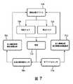
[66] 対象者12における右及び/又は左心房が過負荷になっているかの決定、及びそれに続くそのような決定に基づいた圧力支援治療の調節が、図7に示される。図7において図示されるように、全身の脈到達センサ(例えば、図1において図示されるセンサ18及び19を備える)(704)からの情報、及び/又は他の情報に基づく右心房が過負荷になっている(右心臓前負荷、血液ボリューム過負荷)(702)という決定に応じて、換気支援デバイス(例えば、圧力生成器14)(706)は、患者(例えば、対象者12)(710)のためにlpPAP(708)を生成するように制御される。舌下PPGセンサ(例えば、センサ18)(714)からの情報、及び/又は他の情報に基づく左心房が過負荷になっている(左心臓前負荷、全身静脈血液ボリューム過負荷)(712)という決定に応じて、換気支援デバイス(706)は、患者(710)のためにhpPAP(716)を生成するように制御される。 [66] Determining whether the right and/or left atrium in
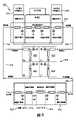
[67] 図8は、対象者12における右心房の過負荷が起こったと決定することに応じて対象者12(図1)に提供される圧力支援の圧力レベルプロファイル800を示す。圧力レベルプロファイル800は、心臓周期802の拡張期フェーズ806及び収縮期フェーズ808、並びに呼吸周期804の吸気フェーズ810及び呼気フェーズ812に関連して図示されている。図8において図示されるように、右心房の過負荷が起こったという決定に応じて、吸気の期間中に、圧力レベルは、圧力支援治療レジーム(例えば、典型的なCPAP治療レジーム)によって示されるレベルよりも上に増加され(814)、心臓周期802の収縮期及び拡張期フェーズに対応するタイミング818、820で、増加された圧力レベルを中心に振動させられる(816)。 [67] FIG. 8 illustrates a pressure level profile 800 of pressure support provided to subject 12 (FIG. 1) in response to determining that right atrial overload in
[68] 図9は、対象者における左心房の過負荷が起こったと決定することに応じて対象者(例えば、図1において図示される対象者12)に提供される圧力支援の圧力レベルプロファイル900を示す。圧力レベルプロファイル900は、心臓周期902の拡張期フェーズ906及び収縮期フェーズ908、並びに呼吸周期904の吸気フェーズ910及び呼気フェーズ912に関連して図示されている。図9において図示されるように、左心房の過負荷が起こったという決定に応じて、圧力レベルは、呼気の期間中914の圧力レベルが吸気の期間中916の圧力レベルよりも高くなるように調節される。加えて、圧力レベルは、呼気の期間中920の振幅の方が吸気の期間中922の振幅よりも大きくなるような振動振幅920、922で、対象者における心臓周期の収縮期及び拡張期フェーズに対応する振動タイミング924で、吸息及び呼息の期間中、調節された圧力レベルを中心に振動する(918)。 [68] FIG. 9 depicts a pressure level profile 900 of pressure support provided to a subject (eg, subject 12 illustrated in FIG. 1) in response to determining that left atrial overload in the subject has occurred. indicates Pressure level profile 900 is illustrated in relation to
[69] 図1に戻ると、システム10の動作の非限定的な例として、光学的PPGセンサ18は、対象者12における内部頚静脈の支脈に位置し、呼吸作用に関連する静脈血貯留及び右心房の充填を監視する。パラメータコンポーネント40及び/又は血行動態コンポーネント44は、センサ17、18及び/又は19からの情報に基づいて、脈拍数及び呼吸数を決定する。信号振幅(例えばセンサ18からのもの)は、呼吸作用の期間中の心臓の努力、及び静脈の膨張を表し、これは血液蓄積に対応する。信号の振幅が対象者12に関する所定の範囲の外にある場合、治療圧力レベルは、吸気周期の間増加される。対象者12は、呼吸に必要とされる筋肉運動を減少させることによって自律的に応答する。筋肉運動の減少に対するこの応答は、次の呼吸周期における舌下静脈のセンサ18からの信号の振幅の変化に基づいて決定される。これに従い、センサ19からの情報は、移行時間における変化を決定するために使用される。 [69] Returning to FIG. 1, as a non-limiting example of the operation of
[70] システム10の動作の第2の非限定的な例として、血行動態コンポーネント44は、血液波の移行時間の増加を検知し、(例えば、上述のように)肺循環系におけるボリューム過負荷が起こったことを決定するように構成される。この過負荷は、鬱血性心不全(CHF:congestive heart failure)の患者における典型的な症状である。移行時間の増加は、容量性の、適合性の高い肺血管における蓄積された血液の量と相関関係を有する。このような実施形態において、調節コンポーネント46は、呼気の期間中の治療圧力レベルを、呼気の期間中に対象者12による積極的な筋肉運動を必要とするレベルに増加させるように圧力生成器14を制御するように構成される。圧力レベルの増加は、肺胞内毛細血管の血管抵抗の増加を引き起こし、従って、肺静脈に流入する血液がより少なくなり、肺静脈(肺胞外静脈)における経壁圧の増加が、心臓の左側の前負荷を増加させる。これらの効果は両方とも、肺循環系に蓄積された血液が減少される(例えば、血行動態的コンポーネント44によって決定された肺移行時間の減少において明白になる)ように肺循環の平衡をとることに貢献する。 [70] As a second non-limiting example of the operation of
[71] 図1に戻ると、ユーザインタフェース22は、システム10と対象者12及び/又は他のユーザとの間にインタフェースを提供するように構成され、これを通じて対象者12及び/又は他のユーザはシステム10に情報を提供するとともに、これから情報を受け取るように構成される。例えば、ユーザインタフェース22は、圧力支援治療のための制御パラメータを指定する対象者12及び/又は他のユーザからの制御入力の入力及び/又は選択、及び/又は他の情報を受け取るように構成される。他のユーザには、介護者、医者、意志決定者及び/又は他のユーザが含まれる。ユーザインタフェース22は、集合的に「情報」と称されるデータ、キュー、結果、及び/又は命令、並びに任意の他の通信可能なアイテムが、ユーザ(例えば、対象者12)と圧力生成器14、センサ17、18、19、プロセッサ20、電子的記憶装置24、及び/又はシステム10の他のコンポーネントのうちの1つ又は複数との間で通信されることを可能にする。ユーザインタフェース22に含まれるのに適切なインタフェースデバイスの例としては、キーパッド、ボタン、スイッチ、キーボード、ノブ、レバー、表示スクリーン、タッチスクリーン、スピーカ、マイクロフォン、インジケータライト、可聴アラーム、プリンタ、触覚フィードバックデバイス及び/又は他のインタフェースデバイスがある。いくつかの実施形態において、ユーザインタフェース22は、複数の別個のインタフェースを備える。いくつかの実施形態において、ユーザインタフェース22は、圧力生成器14と一体的に提供される少なくとも1つのインタフェースを備える。 [71] Returning to FIG. 1, user interface 22 is configured to provide an interface between
[72] 配線で接続された又は無線の他の通信技術も、本開示によってユーザインタフェース22として想定されることを理解されたい。例えば、本開示は、ユーザインタフェース22が、電子的記憶装置24によって提供される取り外し可能な記憶装置インタフェースと一体化されることを想定する。この例において、情報は、システム10の実施態様をユーザがカスタマイズすることを可能にする取り外し可能な記憶装置(例えば、スマートカード、フラッシュドライブ、取り外し可能ディスクなど)からシステム10にロードされる。ユーザインタフェース22としてシステム10とともに使用されることに適合された他の例示的な入力デバイス及び技術としては、これらに限定されるものではないが、RS-232ポート、RFリンク、IRリンク、モデム(電話機、ケーブルなど)がある。端的に言えば、システム10と情報を通信するための任意の技術が、本開示によってユーザインタフェース22として想定される。 [72] It should be understood that other communication technologies, wired or wireless, are also contemplated as user interface 22 by this disclosure. For example, the present disclosure contemplates user interface 22 being integrated with a removable storage device interface provided by
[73] いくつかの実施形態において、電子的記憶装置24は、情報を電子的に記憶する電子的記憶媒体を備える。電子的記憶装置24の電子的記憶媒体は、システム10と一体的に(すなわち、実質的に取り外し不可能に)提供されるシステム記憶装置;例えばポート(例えば、USBポート、ファイアワイヤポートなど)又はドライブ(例えば、ディスクドライブ)を介してシステム10に取り外し可能に接続される取り外し可能な記憶装置;システム10によって無線でアクセスされる離間して位置する電子的(例えば、「クラウド」)記憶装置;及び/又は他の電子的記憶装置を備える。電子的記憶装置24は、光学的に読み取り可能な記憶媒体(例えば、光学的ディスクなど)、磁気的に読み取り可能な記憶媒体(例えば、磁気テープ、磁気的ハードドライブ、フロッピードライブなど)、電荷ベースの記憶媒体(例えば、EPROM、RAMなど)、固体記憶媒体(例えば、フラッシュドライブなど)、及び/又は他の電子的に読み取り可能な記憶媒体のうちの1つ又は複数を備える。電子的記憶装置24は、ソフトウェアアルゴリズム、プロセッサ20によって決定された情報、ユーザインタフェース22を介して受信された情報、及び/又はシステム10が本明細書において説明されたように機能することを可能にする他の情報を記憶する。電子的記憶装置24は、(全体的に又は部分的に)システム10内の個別のコンポーネントであってよく、又は電子的記憶装置24は、システム10の1つ又は複数の他のコンポーネント(例えば、ユーザインタフェース22、プロセッサ20など)と(全体的に又は部分的に)一体化されて提供されてよい。 [73] In some embodiments,
[74] 図10は、換気支援システムによって、対象者における肺及び全身循環を促進するための方法1000を示す。システムは、圧力生成器、第1のセンサ、第2のセンサ、1つ又は複数のハードウェアプロセッサ、及び/又は他のコンポーネントを備える。1つ又は複数のハードウェアプロセッサは、コンピュータプログラムコンポーネントを実行する機械可読命令によって構成される。コンピュータプログラムコンポーネントは、制御コンポーネント、血行動態コンポーネント、調節コンポーネント、及び/又は他のコンポーネントを含む。以下に提示される方法1000の動作は、例示的であるものと意図される。いくつかの実施形態において、方法1000は、説明されない1つ又は複数の追加的な動作によって達成され、及び/又は論じられる動作のうちの1つ又は複数の動作なしに達成される。加えて、図10において示され、以下において説明される方法1000の動作の順番は、限定を意図するものではない。 [74] FIG. 10 illustrates a method 1000 for promoting pulmonary and systemic circulation in a subject with a ventilation support system. A system comprises a pressure generator, a first sensor, a second sensor, one or more hardware processors, and/or other components. The one or more hardware processors are configured with machine-readable instructions to execute computer program components. Computer program components include control components, hemodynamic components, regulatory components, and/or other components. The operations of method 1000 presented below are intended to be exemplary. In some embodiments, method 1000 is accomplished with one or more additional acts not described and/or without one or more of the discussed acts. Additionally, the order of operations of method 1000 illustrated in FIG. 10 and described below is not intended to be limiting.
[75] いくつかの実施形態において、方法1000は、1つ又は複数の処理デバイス(例えば、デジタルプロセッサ、アナログプロセッサ、情報を処理するように設計されたデジタル回路、情報を処理するように設計されたアナログ回路、ステートマシン、及び/又は情報を電子的に処理するための他の機構)において実施される。1つ又は複数の処理デバイスは、電子的記憶媒体に電子的に記憶された命令に応じて方法1000の動作のうちのいくつか又は全てを実行する1つ又は複数のデバイスを含む。1つ又は複数の処理デバイスは、ハードウェア、ファームウェア、及び/又はソフトウェア通じて、方法1000の動作のうちの1つ又は複数の実行のために特別に設計されるよう構成された1つ又は複数のデバイスを含む。 [75] In some embodiments, method 1000 uses one or more processing devices (eg, digital processors, analog processors, digital circuits designed to process information, analog circuits, state machines, and/or other mechanisms for electronically processing information). The one or more processing devices include one or more devices that perform some or all of the acts of method 1000 in response to instructions electronically stored on electronic storage media. One or more processing devices configured through hardware, firmware, and/or software to be specially designed for performing one or more of the operations of method 1000 devices.
[76] 動作1002において、呼吸可能ガスの圧流が、圧力支援治療レジームに従って生成される。圧力支援治療レジームは、対象者による吸息及び呼息の期間中に圧力生成器によって提供される呼吸可能ガスの圧流の圧力レベルを示す。いくつかの実施形態において、動作1002は、(図1において図示され、本明細書において説明される)圧力生成器14と同一又は類似の圧力生成器によって実施される。 [76] At
[77] 動作1004において、心臓前負荷の期間中の静脈血液蓄積に関する情報を搬送する出力信号が生成される。いくつかの実施形態において、出力信号は、対象者の呼吸周期によって変調された舌下静脈の拍動に関する情報を搬送する出力信号を生成するように構成された舌下フォトプレチィスモグラフィ(PPG)センサによって生成される。いくつかの実施形態において、動作1004は、(図1において図示され、本明細書において説明される)センサ18と同一又は類似のセンサによって実施される。 [77] In
[78] 動作1006において、心臓血液ボリューム過負荷に関する情報を搬送する出力信号が生成される。いくつかの実施形態において、出力信号は、対象者の額、こめかみ、耳又は指に取り外し可能に結合されるように構成された全身PPGセンサによって生成される。いくつかの実施形態において、動作1006は、(図1において図示され、本明細書において説明される)センサ19と同一又は類似のセンサによって実施される。 [78] At operation 1006, an output signal is generated that conveys information about cardiac blood volume overload. In some embodiments, the output signal is generated by a whole body PPG sensor configured to be removably coupled to the subject's forehead, temples, ears or fingers. In some embodiments, operation 1006 is performed by a sensor that is the same as or similar to sensor 19 (shown in FIG. 1 and described herein).
[79] 動作1008において、肺及び全身循環を促進するために、出力信号に基づいて、呼吸可能ガスの圧流が調節される。いくつかの実施形態において、圧力生成器は、吸息及び呼息のうちの一方又は両方の期間中に呼吸可能ガスの圧流の圧力レベルを調節するように制御される。いくつかの実施形態において、呼吸可能ガスの圧流の圧力レベルを調節することを圧力生成器に行わせることは、対象者における心臓前負荷の期間中の静脈血液蓄積の量及び/又は心臓血液量過多ストレスの量に対応する量だけ、圧力レベルを調節することを有する。いくつかの実施形態において、動作1008は、(図1において図示され、本明細書において説明される)調節コンポーネント46と同一又は類似のプロセッサコンポーネントによって実施される。 [79] At
[80] いくつかの実施形態において、方法1000は、1つ又は複数のハードウェアプロセッサのうちの血行動態コンポーネントによって、第1のセンサ及び第2のセンサからの出力信号に基づいて、対象者において心房細動の発症が起こっているか又は起こりそうであるかを決定するステップと、心房細動が起こっている又は起こりそうであるという決定に応じて、1つ又は複数のハードウェアプロセッサのうちの調節コンポーネントによって、肺及び全身循環を促進し、心房細動の発症を阻止又は防止するために、吸息及び呼息のうちの一方又は両方の期間中に圧力レベルを調節するように圧力生成器を制御するステップと、を有する。いくつかの実施形態において、心房細動の発症が起こっているか又は起こりそうであるかを決定するステップは、対象者の肺循環系における血液波の経肺的な移行時間を決定するステップを有する。移行時間は、対象者の右心房、肺静脈及び左心房において蓄積された血液の量に対応する。 [80] In some embodiments, the method 1000 is performed by a hemodynamic component of the one or more hardware processors in a subject based on output signals from a first sensor and a second sensor. determining whether an onset of atrial fibrillation is occurring or is likely to occur; A pressure generator with a regulation component to regulate the pressure level during one or both of inspiration and expiration to promote pulmonary and systemic circulation and inhibit or prevent the onset of atrial fibrillation. and controlling the In some embodiments, determining whether an onset of atrial fibrillation is occurring or likely to occur comprises determining a transpulmonary transit time of blood waves in the pulmonary circulation of the subject. The transition time corresponds to the amount of blood accumulated in the subject's right atrium, pulmonary veins and left atrium.
[81] いくつかの実施形態において、方法1000は、1つ又は複数のハードウェアプロセッサのうちの血行動態コンポーネントによって、第1のセンサ及び第2のセンサの出力信号に基づいて、対象者の右及び/又は左心房の過負荷が起こったかを決定するステップを有する。このような実施形態において、方法1000は、右心房の過負荷が起こったと決定することに応じて、吸息の期間中の圧力レベルを、圧力支援治療レジームによって示されるレベルよりも上に増加させることと、対象者における心臓周期の収縮期及び拡張期フェーズに対応するタイミングで、増加された圧力レベルを中心に圧力を振動させることと、を1つ又は複数のハードウェアプロセッサのうちの調節コンポーネントによって、圧力生成器に行わせるステップを更に有する。そのような実施形態において、方法1000は、左心房の過負荷が起こったと決定することに応じて、吸息及び呼息の期間中の圧力レベルを、呼息の期間中の圧力レベルが吸息の期間中の圧力レベルよりも高くなるように調節することと、呼息の期間中の方が吸息の期間中よりも大きくなるような振動振幅で、心臓周期の収縮期及び拡張期フェーズに対応する振動タイミングで、吸息及び呼息の期間中、調節された圧力レベルを中心に圧力を振動させることと、を1つ又は複数のハードウェアプロセッサのうちの調節コンポーネントによって、圧力生成器に行わせるステップを更に有する。 [81] In some embodiments, the method 1000 is performed by a hemodynamic component of the one or more hardware processors to determine the right side of the subject based on the output signals of the first sensor and the second sensor. and/or determining if left atrial overload has occurred. In such embodiments, the method 1000 increases the pressure level during inspiration above that indicated by the pressure support treatment regime in response to determining that right atrial overload has occurred. and oscillating the pressure about the increased pressure level with timing corresponding to the systolic and diastolic phases of the cardiac cycle in the subject. and causing the pressure generator to perform. In such an embodiment, the method 1000 adjusts the pressure level during inspiration and expiration, and the pressure level during expiration, in response to determining that left atrial overload has occurred. during the systolic and diastolic phases of the cardiac cycle by adjusting the pressure level to be higher than during exhalation and the oscillation amplitude to be greater during exhalation than during inhalation. Oscillating the pressure about the regulated pressure level during inspiration and expiration with corresponding oscillation timing; further comprising the step of causing to occur.
[82] 上に提供された説明は、最も実際的で好ましいと現在のところ考えられる実施形態に基づき、例示を目的として詳細を提供するが、そのような詳細は、その目的のためだけのものであり、本開示は、明確に開示された実施形態に限定されるものではなく、それどころか、添付の特許請求の範囲の精神及び範囲内にある修正及び等価な構成をカバーするものと意図されることを理解されたい。例えば、本開示は、可能な限り、任意の実施形態の1つ又は複数の特徴が、任意の他の実施形態の1つ又は複数の特徴と組み合わされ得ることを想定することを理解されたい。 [82] Although the description provided above provides details for purposes of illustration, based on what is presently believed to be the most practical and preferred embodiments, such details are provided for that purpose only. and this disclosure is not limited to the specifically disclosed embodiments, but rather is intended to cover modifications and equivalent arrangements within the spirit and scope of the appended claims. Please understand. For example, it should be understood that, wherever possible, this disclosure contemplates that one or more features of any embodiment can be combined with one or more features of any other embodiment.
[83] 特許請求の範囲において、括弧の間に置かれた任意の参照符号は、請求項を限定するものと解釈されるべきではない。「備える」又は「含む」という語は、請求項において列記されたもの以外の要素又はステップの存在を排除するものではない。いくつかの手段を列挙するデバイスの請求項において、これらの手段のうちのいくつかは、1つの同一のハードウェアアイテムによって具現化されてよい。ある要素に先行する「1つの(「a」又は「an」)という語は、そのような要素が複数存在することを排除するものではない。いくつかの手段を列挙する任意のデバイスの請求項において、これらの手段のうちのいくつかは、1つの同一のハードウェアアイテムによって具現化されてよい。特定の要素が互いに異なる従属請求項において記載されるという単なる事実は、これらの要素が組み合わされて使用され得ないことを示すものではない。 [83] In the claims, any reference signs placed between parentheses shall not be construed as limiting the claim. The word "comprising" or "including" does not exclude the presence of elements or steps other than those listed in a claim. In a device claim enumerating several means, several of these means may be embodied by one and the same item of hardware. The word "a" or "an" preceding an element does not exclude the presence of a plurality of such elements. In any device claim enumerating several means, several of these means may be embodied by one and the same item of hardware. The mere fact that certain elements are recited in mutually different dependent claims does not indicate that these elements cannot be used in combination.
Claims (12)
Translated fromJapanese前記対象者における血行動態的活動に関する情報を搬送する出力信号を生成する複数のセンサと、
機械可読命令によって、前記出力信号に基づいて前記1つ又は複数の血行動態パラメータを決定し、決定された前記1つ又は複数の血行動態パラメータに基づいて、前記対象者における前記心房伸展を決定するように構成される、1つ又は複数のハードウェアプロセッサと、
を備え、
前記複数のセンサは、前記対象者における第1の位置に配置される第1のフォトプレチィスモグラフィ(PPG)センサと、前記対象者における前記第1の位置とは異なる第2の位置に配置される第2のPPGセンサとを含む、感知及び監視システムであって、
換気支援システムの一部である圧力生成器を更に備え、
前記1つ又は複数の血行動態パラメータは、前記第2のPPGセンサからの出力信号に基づいて決定された心房期外収縮を含み、
心房期外収縮の検知に応じて、前記1つ又は複数のハードウェアプロセッサは、前記対象者に対して換気支援を提供するために前記圧力生成器を始動させ、
前記1つ又は複数のハードウェアプロセッサは、前記対象者における過負荷及び/又は心房伸展の反転を示す前記第1のPPGセンサからの出力信号に基づいて、前記換気支援の成功を確認する、
感知及び監視システム。A sensing and monitoring system for measuring atrial stretching in a subject based on one or more hemodynamic parameters, said sensing and monitoring system comprising:
a plurality of sensors that produce output signals conveying information about hemodynamic activity in the subject;
Machine readable instructions determine the one or more hemodynamic parameters based on the output signal and determine the atrial expansion in the subject based on the determined one or more hemodynamic parameters. one or more hardware processors configured to
with
Theplurality of sensors comprises a first photoplethysmography (PPG) sensor positioned at a first location on the subject and a second location on the subject different from the first location. a second PPG sensor positionedat
further comprising a pressure generator that is part of the ventilation support system;
the one or more hemodynamic parameters includes a premature atrial contraction determined based on an output signal from the second PPG sensor;
In response to detecting an atrial extrasystole, the one or more hardware processors activate the pressure generator to provide ventilatory support to the subject;
the one or more hardware processors confirming successful ventilatory support based on output signals from the first PPG sensor indicative of overload and/or reversal of atrial stretch in the subject;
Sensing and monitoring system .
前記複数のセンサは、
前記対象者における心臓前負荷の期間中の静脈血液蓄積に関する情報を搬送する出力信号を生成する第1のPPGセンサと、
前記対象者における心臓活動及び/又は全身動脈循環に関する情報を搬送する出力信号を生成する第2のPPGセンサと、
を備え、
前記1つ又は複数のハードウェアプロセッサは、前記第1のPPGセンサ及び前記第2のPPGセンサからの前記出力信号に基づいて、肺及び全身循環を促進するために吸息及び呼息のうちの一方又は両方の期間中に前記呼吸可能ガスの圧流の前記圧力レベルを調節するように前記圧力生成器を制御し、
前記1つ又は複数のハードウェアプロセッサは、
前記第1のセンサ及び前記第2のセンサからの前記出力信号に基づいて、前記対象者において心房細動の発症が起こっているか又は起こりそうであるかを決定し、
心房細動が起こっている又は起こりそうであるという決定に応じて、前記肺及び全身循環を促進し、心房細動の前記発症を阻止又は防止するために、吸息及び呼息のうちの一方又は両方の期間中に前記圧力レベルを調節するように前記圧力生成器を制御する、請求項1に記載の感知及び監視システム。The pressure generator generates a pressure flow of breathable gas for delivery to the subject's airway according to a pressure support treatment regime, the pressure support treatment regime comprising inhalation and exhalation by the subject. indicating the pressure level of the pressurized flow of breathable gas provided by the pressure generator during a period of
Theplurality of sensors are
a first PPG sensor that produces an output signal that conveys information about venous blood accumulation during periods of cardiac preload in the subject;
a second PPG sensor that produces an output signal that conveys information about cardiac activity and/or systemic arterial circulation in the subject;
with
The one or more hardware processors, based on the output signals from the first PPG sensor and the second PPG sensor, select one of inhalation and exhalation to facilitate pulmonary and systemic circulation. controlling the pressure generator to adjust the pressure level of the pressurized flow of breathable gas during one or both periods;
The one or more hardware processors are
determining whether an episode of atrial fibrillation has occurred or is likely to occur in the subject based on the output signals from the first sensor and the second sensor;
responsive to the determination that atrial fibrillation is occurring or is likely to occur, one of inspiration and expiration to promote said pulmonary and systemic circulation and to arrest or prevent said onset of atrial fibrillation; 2. The sensing and monitoring system of claim 1, wherein the pressure generator is controlled to adjust the pressure level during either or both periods .
前記右心房の過負荷が起こったと決定することに応じて、吸息の期間中の前記圧力レベルを、前記圧力支援治療レジームによって示される前記圧力レベルよりも上に増加させることと、前記対象者における心臓周期の収縮期及び拡張期フェーズに対応するタイミングで、増加された前記圧力レベルを中心に圧力を振動させることと、を前記圧力生成器に行わせ、
前記左心房の過負荷が起こったと決定することに応じて、
吸息及び呼息の期間中の前記圧力レベルを、呼息の期間中の前記圧力レベルが吸息の期間中の前記圧力レベルよりも高くなるように調節することと、
呼息の期間中の方が吸息の期間中よりも大きくなるような振動振幅で、前記心臓周期の前記収縮期及び拡張期フェーズに対応する振動タイミングで、吸息及び呼息の期間中、調節された前記圧力レベルを中心に前記圧力を振動させることと、
を、前記圧力生成器に行わせる、請求項2に記載の感知及び監視システム。The one or more hardware processors may further determine whether overload of the subject's right and/or left atrium has occurred based on the output signals of the first PPG sensor and the second PPG sensor. to determine
increasing the pressure level during inspiration above the pressure level exhibited by the pressure support treatment regime in response to determining that the right atrial overload has occurred; and causing the pressure generator to oscillate pressure about the increased pressure level with timing corresponding to the systolic and diastolic phases of the cardiac cycle in
In response to determining that left atrial overload has occurred,
adjusting the pressure level during inspiration and expiration such that the pressure level during expiration is higher than the pressure level during inspiration;
during inspiration and expiration, with oscillation amplitudes that are greater during expiration than during inspiration, and with oscillation timings corresponding to said systolic and diastolic phases of said cardiac cycle; oscillating the pressure about the adjusted pressure level;
3. The sensing and monitoring system of claim2 , wherein the pressure generator performs:
前記複数のセンサが、前記対象者における血行動態的活動に関する情報を搬送する出力信号を生成するステップと、
前記1つ又は複数のハードウェアプロセッサが、前記出力信号に基づいて前記1つ又は複数の血行動態パラメータを決定するステップと、
前記1つ又は複数のハードウェアプロセッサが、決定された前記1つ又は複数の血行動態パラメータに基づいて、前記対象者における前記心房伸展を決定するステップと、
を有し、
前記複数のセンサは、前記対象者における第1の位置に配置される第1のフォトプレチィスモグラフィ(PPG)センサと、前記対象者における前記第1の位置とは異なる第2の位置に配置される第2のPPGセンサとを含む、方法において、
前記感知及び監視システムは圧力生成器を更に備え、
前記1つ又は複数の血行動態パラメータは、前記第2のPPGセンサからの出力信号に基づいて決定された心房期外収縮を含み、前記方法は、
前記1つ又は複数のハードウェアプロセッサが、心房期外収縮の検知に応じて、前記対象者に対して換気支援を提供するために前記圧力生成器を始動させるステップと、
前記1つ又は複数のハードウェアプロセッサが、前記対象者における過負荷及び/又は心房伸展の反転を示す前記第1のPPGセンサからの出力信号に基づいて、前記換気支援の成功を確認するステップと、
を更に有する、方法。A methodof operating a sensing and monitoring system for measuring atrial stretching in a subject based on one or more hemodynamic parameters and comprisinga plurality of sensors and one or more hardware processors. wherein the method comprises:
theplurality of sensors producing output signals conveying information about hemodynamic activityin the subject;
the one or more hardware processors determining the one or more hemodynamic parameters basedon the output signals;
the one or more hardware processors determining the atrial extension in the subject basedon the determined one or more hemodynamic parameters;
has
Theplurality of sensors comprises a first photoplethysmography (PPG) sensor positioned at a first location on the subject and a second location on the subject different from the first location. a second PPG sensor positionedat
the sensing and monitoring system further comprising a pressure generator;
The one or more hemodynamic parameters include a premature atrial contraction determined based on an output signal from the second PPG sensor, the method comprising:
the one or more hardware processors activating the pressure generator to provide ventilatory support to the subject in response to detection of an atrial extrasystole;
the one or more hardware processors confirming successful ventilatory support based on output signals from the first PPG sensor indicative of overload and/or reversal of atrial stretch in the subject; ,
The method further comprising:
前記第1のPPGセンサが、前記対象者における心臓前負荷の期間中の静脈血液蓄積に関する情報を搬送する出力信号を生成するステップと、
前記第2のPPGセンサが、前記対象者における心臓活動及び/又は全身動脈循環に関する情報を搬送する出力信号を生成するステップと、
前記1つ又は複数のハードウェアプロセッサが、前記第1のPPGセンサ及び前記第2のPPGセンサからの前記出力信号に基づいて、肺及び全身循環を促進するために吸息及び呼息のうちの一方又は両方の期間中に前記呼吸可能ガスの圧流の前記圧力レベルを調節するように前記圧力生成器を制御するステップと、
前記1つ又は複数のハードウェアプロセッサが、前記第1のPPGセンサ及び前記第2のPPGセンサからの前記出力信号に基づいて、前記対象者において心房細動の発症が起こっているか又は起こりそうであるかを決定するステップと、
心房細動が起こっている又は起こりそうであるという決定に応じて、前記1つ又は複数のハードウェアプロセッサが、前記肺及び全身循環を促進し、心房細動の前記発症を阻止又は防止するために、吸息及び呼息のうちの一方又は両方の期間中に前記圧力レベルを調節するように前記圧力生成器を制御するステップと、
を更に有する、請求項7に記載の方法。the pressure generator generating a pressure flow of breathable gas for delivery to the airways of the subject accordingto a pressure support treatment regime, the pressure support treatment regime comprising inhalation by the subject; and indicating a pressure level of the pressurized flow of breathable gas provided by the pressure generator during exhalation;
said first PPG sensor producing an output signal conveying information regarding venous blood accumulation during periods of cardiac preloadin said subject;
said second PPG sensor producing an output signal conveying information about cardiac activity and/or systemic arterialcirculation in said subject;
The one or more hardware processors, based on the output signals from the first PPG sensor and the second PPG sensor, select one of inhalation and exhalation to facilitate pulmonary and systemic circulation. controlling the pressure generator to adjust the pressure level of the pressurized flow of breathable gas during one or both periods;
The one or more hardware processors determine whether an onset of atrial fibrillation is occurring or likely to occur in the subject based on the output signals from the first PPG sensor and the second PPG sensor. determining if there is
In response to determining that atrial fibrillation is occurring or is likely to occur, the one or more hardware processors promote the pulmonary and systemic circulation to inhibit or prevent the onset of atrial fibrillation. and controlling the pressure generator to adjust the pressure level during one or both of inspiration and expiration;
8. The method of claim7 , further comprising:
前記右心房の過負荷が起こったと決定することに応じて、吸息の期間中の前記圧力レベルを、前記圧力支援治療レジームによって示される前記圧力レベルよりも上に増加させることと、前記対象者における心臓周期の収縮期及び拡張期フェーズに対応するタイミングで、増加された前記圧力レベルを中心に圧力を振動させることとを、前記1つ又は複数のハードウェアプロセッサが、前記圧力生成器に行わせるステップと、
前記1つ又は複数のハードウェアプロセッサが、前記左心房の過負荷が起こったと決定することに応じて、
吸息及び呼息の期間中の前記圧力レベルを、呼息の期間中の前記圧力レベルが吸息の期間中の前記圧力レベルよりも高くなるように調節することと、
呼息の期間中の方が吸息の期間中よりも大きくなるような振動振幅で、前記心臓周期の前記収縮期及び拡張期フェーズに対応する振動タイミングで、吸息及び呼息の期間中、調節された前記圧力レベルを中心に前記圧力を振動させることと、
を、前記1つ又は複数のハードウェアプロセッサが、前記圧力生成器に行わせるステップと、
を更に有する、請求項8に記載の方法。The one or more hardware processors determine whether overload of the subject's right and/or left atrium has occurred based on the output signalsof the first PPG sensor and the second PPG sensor. and
increasing the pressure level during inspiration above the pressure level exhibited by the pressure support treatment regime in response to determining that the right atrial overload has occurred; and oscillating pressure about the increased pressure level at times corresponding to the systolic and diastolic phases of the cardiac cyclein the one or more hardware processors. and
In response to theone or more hardware processors determining that the left atrial overload has occurred,
adjusting the pressure level during inspiration and expiration such that the pressure level during expiration is higher than the pressure level during inspiration;
during inspiration and expiration, with oscillation amplitudes that are greater during expiration than during inspiration, and with oscillation timings corresponding to said systolic and diastolic phases of said cardiac cycle; oscillating the pressure about the adjusted pressure level;
the one or more hardware processorscausing the pressure generator to perform
9. The method of claim8 , further comprising:
Applications Claiming Priority (3)
| Application Number | Priority Date | Filing Date | Title |
|---|---|---|---|
| US201662436465P | 2016-12-20 | 2016-12-20 | |
| US62/436,465 | 2016-12-20 | ||
| PCT/EP2017/083691WO2018115047A1 (en) | 2016-12-20 | 2017-12-20 | Facilitating pulmonary and systemic hemodynamics cross-reference to related applications |
Publications (3)
| Publication Number | Publication Date |
|---|---|
| JP2020503104A JP2020503104A (en) | 2020-01-30 |
| JP2020503104A5 JP2020503104A5 (en) | 2021-02-04 |
| JP7159163B2true JP7159163B2 (en) | 2022-10-24 |
Family
ID=60857074
Family Applications (1)
| Application Number | Title | Priority Date | Filing Date |
|---|---|---|---|
| JP2019533016AActiveJP7159163B2 (en) | 2016-12-20 | 2017-12-20 | Promotes pulmonary and systemic hemodynamics |
Country Status (4)
| Country | Link |
|---|---|
| US (1) | US11769579B2 (en) |
| EP (1) | EP3559950B1 (en) |
| JP (1) | JP7159163B2 (en) |
| WO (1) | WO2018115047A1 (en) |
Families Citing this family (2)
| Publication number | Priority date | Publication date | Assignee | Title |
|---|---|---|---|---|
| US12059266B2 (en)* | 2020-12-30 | 2024-08-13 | Itamar Medical Ltd. | System and method for arrhythmia detection during an at home sleep test |
| US20230014499A1 (en)* | 2021-07-19 | 2023-01-19 | Cardiac Pacemakers, Inc. | Devices and methods for assessing pulmonary congestion using optical sensing |
Citations (5)
| Publication number | Priority date | Publication date | Assignee | Title |
|---|---|---|---|---|
| JP2004202250A (en) | 2002-12-23 | 2004-07-22 | Pulsion Medical Systems Ag | Measuring apparatus for cardiovascular parameters |
| US20050109339A1 (en) | 2003-09-18 | 2005-05-26 | Stahmann Jeffrey E. | Respiratory therapy control based on cardiac cycle |
| JP2008515494A (en) | 2004-10-06 | 2008-05-15 | レスメド リミテッド | Non-invasive monitoring method and apparatus for respiratory parameters of sleep disordered breathing |
| JP2014171660A (en) | 2013-03-08 | 2014-09-22 | Seiko Epson Corp | Atrial fibrillation analyzation equipment, atrial fibrillation analysis system, atrial fibrillation analysis method and program |
| JP2015526114A (en) | 2012-06-01 | 2015-09-10 | コーニンクレッカ フィリップス エヌ ヴェ | Improving heart rate coherence using a respiratory therapy device |
Family Cites Families (9)
| Publication number | Priority date | Publication date | Assignee | Title |
|---|---|---|---|---|
| DE3242814A1 (en) | 1982-11-19 | 1984-05-24 | Siemens AG, 1000 Berlin und 8000 München | METHOD AND RESPIRATOR FOR BREATHING A PATIENT IN THE HEART RHYMUS AND FOR SUPPORTING THE BLOOD CIRCULATION |
| US5377671A (en) | 1991-04-26 | 1995-01-03 | Cardiopulmonary Corporation | Cardiac synchronous ventilation |
| DE10128979B4 (en) | 2001-06-08 | 2011-12-08 | Corscience Gmbh & Co.Kg | Therapy device and associated control unit |
| US7024235B2 (en)* | 2002-06-20 | 2006-04-04 | University Of Florida Research Foundation, Inc. | Specially configured nasal pulse oximeter/photoplethysmography probes, and combined nasal probe/cannula, selectively with sampler for capnography, and covering sleeves for same |
| US8162841B2 (en)* | 2007-08-31 | 2012-04-24 | Pacesetter, Inc. | Standalone systemic arterial blood pressure monitoring device |
| US8321018B2 (en)* | 2011-02-14 | 2012-11-27 | Pacesetter, Inc. | Systems and methods for reducing occurrences of atrial arrhythmias |
| US20120296216A1 (en)* | 2011-05-16 | 2012-11-22 | Cardiogal Ltd. | Methods and systems of aiming sensor(s) for measuring cardiac parameters |
| US20140058273A1 (en)* | 2012-08-27 | 2014-02-27 | Yale University | Apparatus, Systems and Methods Analyzing Pressure and Volume Waveforms in the Vasculature |
| WO2018115082A1 (en) | 2016-12-20 | 2018-06-28 | Koninklijke Philips N.V. | Patient monitoring |
- 2017
- 2017-12-20JPJP2019533016Apatent/JP7159163B2/enactiveActive
- 2017-12-20EPEP17822267.5Apatent/EP3559950B1/enactiveActive
- 2017-12-20WOPCT/EP2017/083691patent/WO2018115047A1/ennot_activeCeased
- 2017-12-20USUS16/471,150patent/US11769579B2/enactiveActive
Patent Citations (5)
| Publication number | Priority date | Publication date | Assignee | Title |
|---|---|---|---|---|
| JP2004202250A (en) | 2002-12-23 | 2004-07-22 | Pulsion Medical Systems Ag | Measuring apparatus for cardiovascular parameters |
| US20050109339A1 (en) | 2003-09-18 | 2005-05-26 | Stahmann Jeffrey E. | Respiratory therapy control based on cardiac cycle |
| JP2008515494A (en) | 2004-10-06 | 2008-05-15 | レスメド リミテッド | Non-invasive monitoring method and apparatus for respiratory parameters of sleep disordered breathing |
| JP2015526114A (en) | 2012-06-01 | 2015-09-10 | コーニンクレッカ フィリップス エヌ ヴェ | Improving heart rate coherence using a respiratory therapy device |
| JP2014171660A (en) | 2013-03-08 | 2014-09-22 | Seiko Epson Corp | Atrial fibrillation analyzation equipment, atrial fibrillation analysis system, atrial fibrillation analysis method and program |
Also Published As
| Publication number | Publication date |
|---|---|
| WO2018115047A1 (en) | 2018-06-28 |
| US11769579B2 (en) | 2023-09-26 |
| US20200043591A1 (en) | 2020-02-06 |
| JP2020503104A (en) | 2020-01-30 |
| EP3559950A1 (en) | 2019-10-30 |
| EP3559950B1 (en) | 2025-05-21 |
Similar Documents
| Publication | Publication Date | Title |
|---|---|---|
| JP5074191B2 (en) | Non-invasive monitoring method and apparatus for respiratory parameters of sleep disordered breathing | |
| US10398863B2 (en) | Cardiac monitoring and therapy using a device for providing pressure treatment of sleep disordered breathing | |
| JP5289731B2 (en) | Apparatus and computer program for measuring a patient's volomic status indicated by cardiopulmonary blood volume | |
| JP6312708B2 (en) | Method, logical operation apparatus, and system for obtaining parameter representing patient volume responsiveness | |
| JP2010518969A (en) | Operation-based plethysmographic pulse variation detection system and method | |
| EP3522778B1 (en) | An apparatus and method for determining a calibration parameter for a blood pressure measurement device | |
| CN112996434B (en) | Capacity reactivity assessment method and medical equipment | |
| CN112788985A (en) | System and method for using respiratory events in sleep staging | |
| JP7159163B2 (en) | Promotes pulmonary and systemic hemodynamics | |
| US20190175858A1 (en) | Devices and methods for non-invasive cardio-adaptive positive pressure ventilation therapy | |
| JP2020503104A5 (en) |
Legal Events
| Date | Code | Title | Description |
|---|---|---|---|
| A521 | Request for written amendment filed | Free format text:JAPANESE INTERMEDIATE CODE: A523 Effective date:20201217 | |
| A621 | Written request for application examination | Free format text:JAPANESE INTERMEDIATE CODE: A621 Effective date:20201217 | |
| A131 | Notification of reasons for refusal | Free format text:JAPANESE INTERMEDIATE CODE: A131 Effective date:20220128 | |
| A601 | Written request for extension of time | Free format text:JAPANESE INTERMEDIATE CODE: A601 Effective date:20220420 | |
| A521 | Request for written amendment filed | Free format text:JAPANESE INTERMEDIATE CODE: A523 Effective date:20220712 | |
| TRDD | Decision of grant or rejection written | ||
| A01 | Written decision to grant a patent or to grant a registration (utility model) | Free format text:JAPANESE INTERMEDIATE CODE: A01 Effective date:20220913 | |
| A61 | First payment of annual fees (during grant procedure) | Free format text:JAPANESE INTERMEDIATE CODE: A61 Effective date:20221012 | |
| R150 | Certificate of patent or registration of utility model | Ref document number:7159163 Country of ref document:JP Free format text:JAPANESE INTERMEDIATE CODE: R150 |