JP7156892B2 - Motor structure - Google Patents
Motor structureDownload PDFInfo
- Publication number
- JP7156892B2 JP7156892B2JP2018184939AJP2018184939AJP7156892B2JP 7156892 B2JP7156892 B2JP 7156892B2JP 2018184939 AJP2018184939 AJP 2018184939AJP 2018184939 AJP2018184939 AJP 2018184939AJP 7156892 B2JP7156892 B2JP 7156892B2
- Authority
- JP
- Japan
- Prior art keywords
- motor
- case
- stator
- rotor
- shaft
- Prior art date
- Legal status (The legal status is an assumption and is not a legal conclusion. Google has not performed a legal analysis and makes no representation as to the accuracy of the status listed.)
- Active
Links
Images


Classifications
- B—PERFORMING OPERATIONS; TRANSPORTING
- B60—VEHICLES IN GENERAL
- B60K—ARRANGEMENT OR MOUNTING OF PROPULSION UNITS OR OF TRANSMISSIONS IN VEHICLES; ARRANGEMENT OR MOUNTING OF PLURAL DIVERSE PRIME-MOVERS IN VEHICLES; AUXILIARY DRIVES FOR VEHICLES; INSTRUMENTATION OR DASHBOARDS FOR VEHICLES; ARRANGEMENTS IN CONNECTION WITH COOLING, AIR INTAKE, GAS EXHAUST OR FUEL SUPPLY OF PROPULSION UNITS IN VEHICLES
- B60K7/00—Disposition of motor in, or adjacent to, traction wheel
- H—ELECTRICITY
- H02—GENERATION; CONVERSION OR DISTRIBUTION OF ELECTRIC POWER
- H02K—DYNAMO-ELECTRIC MACHINES
- H02K11/00—Structural association of dynamo-electric machines with electric components or with devices for shielding, monitoring or protection
- H02K11/30—Structural association with control circuits or drive circuits
- H—ELECTRICITY
- H02—GENERATION; CONVERSION OR DISTRIBUTION OF ELECTRIC POWER
- H02K—DYNAMO-ELECTRIC MACHINES
- H02K5/00—Casings; Enclosures; Supports
- H02K5/04—Casings or enclosures characterised by the shape, form or construction thereof
- H02K5/18—Casings or enclosures characterised by the shape, form or construction thereof with ribs or fins for improving heat transfer
- B—PERFORMING OPERATIONS; TRANSPORTING
- B62—LAND VEHICLES FOR TRAVELLING OTHERWISE THAN ON RAILS
- B62M—RIDER PROPULSION OF WHEELED VEHICLES OR SLEDGES; POWERED PROPULSION OF SLEDGES OR SINGLE-TRACK CYCLES; TRANSMISSIONS SPECIALLY ADAPTED FOR SUCH VEHICLES
- B62M7/00—Motorcycles characterised by position of motor or engine
- B62M7/12—Motorcycles characterised by position of motor or engine with the engine beside or within the driven wheel
- Y—GENERAL TAGGING OF NEW TECHNOLOGICAL DEVELOPMENTS; GENERAL TAGGING OF CROSS-SECTIONAL TECHNOLOGIES SPANNING OVER SEVERAL SECTIONS OF THE IPC; TECHNICAL SUBJECTS COVERED BY FORMER USPC CROSS-REFERENCE ART COLLECTIONS [XRACs] AND DIGESTS
- Y02—TECHNOLOGIES OR APPLICATIONS FOR MITIGATION OR ADAPTATION AGAINST CLIMATE CHANGE
- Y02T—CLIMATE CHANGE MITIGATION TECHNOLOGIES RELATED TO TRANSPORTATION
- Y02T10/00—Road transport of goods or passengers
- Y02T10/60—Other road transportation technologies with climate change mitigation effect
- Y02T10/64—Electric machine technologies in electromobility
Landscapes
- Engineering & Computer Science (AREA)
- Power Engineering (AREA)
- Physics & Mathematics (AREA)
- Thermal Sciences (AREA)
- Chemical & Material Sciences (AREA)
- Combustion & Propulsion (AREA)
- Transportation (AREA)
- Mechanical Engineering (AREA)
- Arrangement Or Mounting Of Propulsion Units For Vehicles (AREA)
- Motor Or Generator Cooling System (AREA)
- Motor Or Generator Frames (AREA)
Description
Translated fromJapanese本発明は、例えば電気モータを駆動源とする車両に関し、特にモータの構造に関する。 BACKGROUND OF THE INVENTION 1. Field of the Invention The present invention relates to a vehicle using, for example, an electric motor as a drive source, and more particularly to the structure of the motor.
電動車両のコンパクト化のために、駆動源である電気モータをインホイールモータとする構成が有効である。インホイールモータの発熱を、ヒートパイプを介して外部に放熱する構成が提案されている(特許文献1等参照)。 In order to make an electric vehicle compact, it is effective to use an in-wheel motor as the electric motor, which is the drive source. A configuration has been proposed in which the heat generated by the in-wheel motor is radiated to the outside via a heat pipe (see Patent Document 1, etc.).
インホイールモータの構成をよりコンパクトにするために、モータと電力制御部(PCU)とを一体化する構成がある。PCUをモータと一体化する際には、インホイールモータは車輪内部に収められる構造となるため、回路保護の観点からモータの内部にPCUを設けるのが望ましい。このような構成ではモータのみならずPCUからの熱も放熱する必要があるため、上述した従来技術では、その分ヒートパイプを太くしなければならない。しかし従来技術では、ヒートパイプは車輪の軸を通して設けられており、太さにも限度がある。 In order to make the configuration of the in-wheel motor more compact, there is a configuration in which the motor and the power control unit (PCU) are integrated. When the PCU is integrated with the motor, the in-wheel motor has a structure that is housed inside the wheel. Therefore, from the viewpoint of circuit protection, it is desirable to provide the PCU inside the motor. In such a configuration, it is necessary to dissipate heat not only from the motor but also from the PCU. However, in the conventional technology, the heat pipe is provided through the axle of the wheel, and there is a limit to the thickness.
本発明は上記従来例に鑑みてなされたもので、電力制御部を内蔵したモータを効率よく冷却できるモータの構造を提供することを目的とする。 SUMMARY OF THE INVENTION It is an object of the present invention to provide a motor structure capable of efficiently cooling a motor incorporating a power control unit.
上記目的を達成するために本発明は以下の構成を有する。すなわち、本発明の一側面によれば、モータ(11)の構造であって、
ステータ(24)と、
前記ステータ(24)からの磁力によって回転するロータ(23)と、
前記ロータ(23)に連結された、前記モータのケース(21,29)と、
前記ケース(21,29)の内側に配置された、前記ステータ(24)を駆動するための電力制御部(10)と、を有し、
前記電力制御部(10)は前記ステータ(24)に対して固定された熱伝導部材(26)に取り付けられ、
前記ケース(21,29)は、前記ロータ(23)とともに回転するシャフト(112)が通る一対の側面を有し、
前記ケース(21,29)の前記一対の側面には、前記熱伝導部材(26)に対向する内側の表面と、その裏側である外側の表面とに冷却用のフィン(111)を設け、
前記熱伝導部材(26)の一方の面に前記電力制御部(10)が取り付けられ、前記熱伝導部材(26)の他方の面に前記ロータ(23)の回転位置を検出するためのホールセンサを設けたホール素子基板(27)が取り付けられる
ことを特徴とするモータの構造が提供される。In order to achieve the above objects, the present invention has the following configurations. That is, according to one aspect of the present invention, a structure of a motor (11), comprising:
a stator (24);
a rotor (23) rotated by the magnetic force from the stator (24);
a motor case (21, 29) connected to the rotor (23);
a power control unit (10) for driving the stator (24) disposed inside the case (21, 29);
said power control (10) being mounted on a heat conducting member (26) fixed relative to said stator (24);
The cases (21, 29)have apair of side surfaces through which a shaft (112) thatrotates together with the rotor (23) passes,
The pair of side surfaces of the case (21, 29) are provided with cooling fins (111) on the innersurface facing the heat conducting member (26) and the outer surface on the back side thereof ,
The electric power control unit (10) is attached to one surface of the heat conduction member (26), and a Hall sensor for detecting the rotational position of the rotor (23) is mounted on the other surface of the heat conduction member (26). A motor structure is provided characterized in that a Hall element substrate (27) provided with is mounted.
本発明によれば、電力制御部を内蔵したモータを効率よく冷却できる。 ADVANTAGE OF THE INVENTION According to this invention, the motor which incorporated the electric power control part can be cooled efficiently.
[第一実施形態]
●鞍乗型車両の構成
図1(a)に、本実施形態に係る鞍乗型車両である動力付き二輪車1の外観の一例を示す。二輪車1は駆動源としてインホイールモータ(以下、単にモータと呼ぶこともある。)11を有しており、インホイールモータ11をハブとしてその周りにタイヤ12が装着されている。インホイールモータ11は、そのシャフト112でスイングアーム13に軸支され、減速機構や伝達機構を介することなく駆動輪を直に回転させることができる。インホイールモータ11の両側の側面には冷却用のフィン111が設けられており、回転によりその表面に空気の流れを生じ、内部から伝播した熱を効率的に放熱する。インホイールモータ11には、電力制御部(または電力制御回路、PCU)10(図1(b)参照)から電源が供給され、その回転数は、ハンドルのグリップ部に設けたアクセルを運転者が操作することで制御される。[First embodiment]
●Structure of Straddle-Type Vehicle FIG. 1A shows an example of the appearance of a powered two-wheeled vehicle 1 that is a straddle-type vehicle according to the present embodiment. The two-wheeled vehicle 1 has an in-wheel motor (hereinafter simply referred to as a motor) 11 as a drive source, and a tire 12 is mounted around the in-
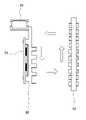
図1(b)に、インホイールモータ11の駆動制御のための制御回路のブロック図を示す。本実施形態のインホイールモータ11は、構造的にはアウターロータ型の表面磁石同期モータ(SPMSM)であり、PCU10を含めてブラシレス直流モータと呼ぶこともある。インホイールモータ11は、PCU10から供給される三相の交流電源により駆動される。この交流電源の各相は正弦波であってもよいし矩形波であってもよい。PCU10は低圧電源(例えば12V電源)104により駆動され、コントローラ101とインバータ102とを含む。コントローラ101には、モータ103からの、ロータの回転位置を検出するためのホールセンサの出力信号(ホールセンサ信号)が入力される。なおモータ103は、インホイールモータ11からPCUを除外した部分を指す。コントローラ101は、入力されたホールセンサ信号に基づいて、インバータ102に対して高圧電源(HVバッテリ)105からの電流に対するスイッチング等の制御を行うための制御信号を入力する。コントローラ101はさらに、アクセル開度を示す信号に応じてインバータ102の出力周波数を制御するために、インバータ102への制御信号のタイミングを調整する。さらに、周波数のみならず電流を制御できるように構成してもよい。 FIG. 1(b) shows a block diagram of a control circuit for drive control of the in-
インバータ102は、コントローラ101からの制御信号に応じて、高圧電源105を三相交流U,V,Wに変換してモータ103へと入力する。モータ103は、入力された電源の周波数に同期して駆動される。またモータ103には温度センサとホールセンサとを備えており、温度センサで検知した温度を示す温度信号と、ホールセンサで検知した磁界を示すホールセンサ信号がコントローラ101へと入力される。ホールセンサ信号は、ロータ表面に、S極とN極とが交互になるよう張り付けられた永久磁石の磁界を検知することで、ロータの電気的な回転位置を検知する。
ここで、本実施形態においては、PCU10は、後述するようにインホイールモータ11の内部に組み込まれている。このように構成されるインホイールモータ11を用いて、二輪車1の駆動輪を回転させ、二輪車1を運転者の意図通りに走行させることができる。 Here, in this embodiment, the PCU 10 is incorporated inside the in-
●インホイールモータの構成
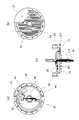
図2(a)はインホイールモータ11の分解斜視図である。インホイールモータ11の主要構成部品は、金属等で形成されたホイールケース21とホイールケース29とにより構成される筐体の内部に収められる。ホイールケース21は、その回転軸部分にシャフト112を通す穴が設けられており、周縁部が張り出した円盤形状を持つ。またその外側および内側の表面には、放熱用のフィン111が設けられている。フィン111は、本例では、互いに並列な複数の細長い張り出しであり、ホイールケース21と一体に成形されている。その高さや本数は、インホイールモータ11の内部で生じる熱を放出するために、その発熱量に応じて決定してよい。ホイールケース29は、ホイールケース21と同様の構成であるが、本例では外周部に設けた周縁部の張り出しがない。しかしホイールケース21と同様の構成としてもよい。ホイールケース21とホイールケース29とは、例えばボルトなどで互いに固定されてインホイールモータ11のケースを構成し、ベアリング22,28を介してシャフト112に取り付けられる。このため、ホイールケース21,29は、スイングアーム13に固定されて回転しないシャフト112に対して回転でき、その外周にタイヤ12が取り付けられて、駆動輪のハブともなる。●Configuration of In-wheel Motor FIG. 2(a) is an exploded perspective view of the in-
ホイールケース21の周縁部の張り出しの内側に沿って、ロータ23が連結或いは固定される。ロータ23は、例えば16個あるいは32個といった複数の永久磁石を、極性を交互に反転させつつ配置して構成されている。これは一般的なアウターロータ型のモータと同様である。一方シャフト112には、回路ケース26が固定される。回路ケース26は、シャフト112を中心とする、例えば金属製の円盤形状の部材である。回路ケース26のホイールケース29に対向する面の一部には、好ましくは回路ケース26と一体的に形成された放熱用のフィンが設けられている。また同じ面の一部には、ホールセンサを設けたホール素子基板27が取り付けられる。また回路ケース26のホール素子基板27と反対側の面には、PCU10を設けたPCU基板25が取り付けられる。PCU基板25とホール素子基板27とは、回路ケース26に穿った通し穴を通して必要な信号線及び電力線で繋げられている。回路ケース26のPCU基板25側の面には、本例ではフィンが設けられていないが、設けてもよい。 A
回路ケース26には、その周囲を取り巻くようにステータ24が取り付けられる。すなわち、ステータ24は、回路ケース26を介してシャフト112に対して固定されている。ステータ24にはインバータ102からからの三相交流電源UVWにそれぞれ接続された巻き線が含まれる。ステータ24はシャフト112に固定されており、その外側のロータ23が回転する。 A
図2(b)は、インホイールモータ11の回転軸に平行な断面を示す断面図である。シャフト112を軸として、ホイールケース21,29により構成された筐体内に、ロータ23、ステータ24、基板ケース26等が収容されている。ここで、基板ケース26は金属等の熱伝導性の高い熱伝導部材であり、基板類を取り付ける部材であるとともに、放熱板としても機能する。そのためPCU基板25は、そこに取り付けた発熱する部品が、直接、あるいは高い熱伝導率を持つ熱伝導素材を介して基板ケース26に接するように、基板ケース26に取り付けられてよい。さらにステータ24も基板ケース26に接触し、その熱が基板ケース26に伝播する。このような構成の結果、ステータ24やPCU基板25の熱は基板ケース26に伝達しやすい。また基板ケース26のフィンが設けられた側の面がホイールケース29に対向しており、ホイールケース29の回転によって、基板ケース26とホイールケース29との間の空間内に空気の流れを生じる。この空気流が、基板ケース26のフィンに接してそれを効果的に冷却する。逆にホール素子基板27は、基板ケース26に取り付けられるものの、基板ケース26からの熱がホール素子に伝播しにくいように取り付けられることが望ましい。 FIG. 2B is a cross-sectional view showing a cross section parallel to the rotating shaft of the in-
図4にその様子を示す。図4は、図2(b)の断面のうち、基板ケース26とホイールケース29とについて、シャフト112から上部を示す。ホイールケース29が回転することで、ホイールケース29に沿って外周側へと向かう空気流が生じ、その空気流はホイールケース21の外縁に当たって基板ケース26側の空間へと向かう。その空気流は基板ケース26によりシャフト112側へと向けられ、シャフト112を挟んだ反対側でも生じている空気流と衝突して、図4に示す矢印のような渦上の対流を引き起こす。この空気の流れにより、PCU基板25やホール素子基板27、ステータ24等で生じて基板ケース26に伝達された熱は、さらにホイールケース29へと伝播される。そして、ホイールケース29の外側表面に設けたフィンから効果的に放熱される。ホイールケース21についても同様にこのような効果が生じ、内部で生じた熱をインホイールモータ11の外部へと効果的に放散できる。 The situation is shown in FIG. 4 shows the
図3(a)~図3(c)に、基板ケース26に対するPCU基板25およびホール素子基板27の取り付けの詳細を示す。図3(a)は基板ケース26のPCU基板25側を、図3(b)はその反対のホール素子基板27側を、図3(c)は断面を示す。PCU基板25とホール素子基板27はそれぞれ、基板ケース26の対向する面の、互いに重ならない位置に取り付けられる。PCU基板25は、その上に設けたインバータ102のFET等のパワー素子251が、基板ケース26に直に接するように取り付けられる。これにより、パワー素子251からの熱が効率的に基板ケース26に伝播される。またホール素子基板27上のホール素子271は、ロータ23の回転位置を検知するために、ロータ側の端部に設けられている。基板ケース26はその外周部をステータ243により囲まれるように構成され、その中心部でシャフト112と結合されている。シャフト112は両端が開いた中空に形成されており、ホイールケース内部の、PCU基板25が取り付けられた面の側に通じる穴41,42が設けられている。二輪車1の本体に搭載された電源から導かれてシャフト112の端部から中空のシャフト内へと挿通された電源ケーブルやその他の制御信号などのケーブル(あるいはハーネス)40は、穴41,42を介してPCU基板25へと導かれ、所定の端子に接続される。PCU基板25とホール素子基板27とを接続するケーブルは、基板ケース26の開口43を通して配線される。このように、PCU基板25とホール素子基板27は、基板ケース26の互いに反対の面に取り付けられる。 3(a) to 3(c) show the details of mounting the
このような構成によってPCU基板25とホール素子基板27との間の配線を簡単化でき、インホイールモータ11の構成をコンパクト化できる。さらに、インホイールモータ11内部への配線を中空のシャフト112を通して実現したことも、インホイールモータ11のコンパクト化に寄与する。またPCU基板25とホール素子基板27とは互いに重複しない位置に設けられているため、PCU基板25の、特にインバータ102により生じる熱によるホール素子回路27への影響を低減できる。 With such a configuration, the wiring between the
なお本実施形態では、ケースに設けたフィンは一定の方向に並列に配置されているが、これに限らない。たとえば、シャフトを中心とした放射状等に配列されてもよい。また直線的な形状のみならず、曲線的な形状であってもよい。また放熱の効率のみならず、風切り音等を考慮して形状を決定してもよい。 In this embodiment, the fins provided on the case are arranged in parallel in a fixed direction, but the present invention is not limited to this. For example, they may be arranged radially around the shaft. Moreover, not only a linear shape but also a curved shape may be used. Further, the shape may be determined in consideration of not only heat radiation efficiency but also wind noise and the like.
なお本実施形態ではインホイールモータ11を動力として用いる車両を二輪車としたが、三輪車や四輪車であってもよい。また駆動輪は後輪に限らず前輪としてもよいし、車両が備える全ての車輪としてもよい。また二輪車であっても前後に車輪を備えているものに限らず、車椅子など進行方向に対して左右に並列な車輪を備えた車両であってもよい。その場合には両輪が駆動輪となり、インホイールモータ11により駆動される。またこのような二輪車や四輪車の場合には、インホイールモータ11はコントローラ101による制御で逆回転(すなわち後退)できるよう構成されていてもよい。さらに車両の駆動輪に限らず、対象を回転させるための動力源として本実施形態に係るインホイールモータ11を用いてもよい。さらに車両の駆動輪としてインホイールモータ11を用いる場合には、走行風を効率的に駆動輪のハブ部分に導くような部材を車両に取り付けてもよい。 In this embodiment, the vehicle using the in-
●実施形態のまとめ
以上説明した本実施形態をまとめると以下のとおりである。
(1)本実施形態に係る第一の発明によれば、モータ(11)の構造であって、
ステータ(24)と、
前記ステータ(24)からの磁力によって回転するロータ(23)と、
前記ロータ(23)に連結された、前記モータのケース(21,29)と、
前記ケース(21,29)の内側に配置された、前記ステータ(24)を駆動するための電力制御部(10)と、を有し、
前記ケース(21,29)に冷却用のフィン(111)を設けたことを特徴とするモータの構造が提供される。●Summary of Embodiments The above-described embodiments are summarized as follows.
(1) According to the first aspect of the present invention, the structure of the motor (11) is
a stator (24);
a rotor (23) rotated by the magnetic force from the stator (24);
a motor case (21, 29) connected to the rotor (23);
a power control unit (10) for driving the stator (24) disposed inside the case (21, 29);
A motor structure is provided, characterized in that the case (21, 29) is provided with cooling fins (111).
それにより、ケースはロータの回転とともに回転し、空気の流れを起こしやすくなるため、モータの冷却効率をより一層向上させることができる。
(2)本実施形態に係る第二の発明によれば、(1)のモータ(11)の構造であって、
前記電力制御部(10)は前記ステータ(24)に対して固定された熱伝導部材(26)に取り付けられ、
前記ケース(21,29)には、前記ロータ(23)とともに回転する軸が通る側面と、前記熱伝導部材(26)に対向する内側の面とに前記フィン(111)が設けられたことを特徴とするモータの構造が提供される。As a result, the case rotates with the rotation of the rotor, making it easier for the air to flow, so that the cooling efficiency of the motor can be further improved.
(2) According to the second aspect of the present invention, the structure of the motor (11) of (1) is
said power control (10) being mounted on a heat conducting member (26) fixed relative to said stator (24);
The case (21, 29) is provided with the fins (111) on the side surface through which the shaft rotating together with the rotor (23) passes and the inner surface facing the heat conducting member (26). A featured motor structure is provided.
それにより、ケースの内部にも冷却用のフィンを設け、さらに冷却効果を向上させることができる。
(3)本実施形態に係る第三の発明によれば、(2)のモータ(11)の構造であって、
前記熱伝導部材(26)には、前記ケース(21,29)の内側の面と対向する面に冷却用のフィン(111)を設けたこと特徴とするモータの構造が提供される。As a result, cooling fins are provided inside the case, and the cooling effect can be further improved.
(3) According to the third aspect of the present invention, the structure of the motor (11) of (2),
A motor structure is provided in which the heat conducting member (26) is provided with cooling fins (111) on the surface facing the inner surface of the case (21, 29).
それにより、熱伝導部材にも冷却用のフィンを設けることによって、さらに冷却効果を向上させることができる。
(4)本実施形態に係る第三の発明によれば、(1)乃至(3)のいずれかのモータ(10)の構造であって、
前記ステータ(24)に対して固定され、前記ロータ(23)と共に回転する前記ケース(21,29)の軸となる、前記ケース(21,29)に対して回動可能な中空のシャフト(112)を更に有し、
前記電力制御部(10)に接続されるハーネスが、前記シャフト(112)内を挿通して前記ケース(21,29)の内部へと配線されることを特徴とするモータの構造が提供される。Accordingly, the cooling effect can be further improved by providing cooling fins on the heat conducting member as well.
(4) According to the third aspect of the present invention, the structure of the motor (10) according to any one of (1) to (3),
a hollow shaft (112) fixed to the stator (24) and rotatable with respect to the case (21,29), which pivots the case (21,29) rotating with the rotor (23); ), and
A motor structure is provided in which a harness connected to the power control unit (10) is inserted through the shaft (112) and wired to the inside of the case (21, 29). .
それにより、モータ内部における配線効率を向上させることができ、モータを小型化することが可能になる。
(5)本実施形態に係る第三の発明によれば、(1)乃至(4)のいずれかの構造を持つモータ(11)の前記ケース(21,29)の外周にタイヤ(12)を取り付けた駆動輪を有することを特徴とする車両が提供される。As a result, the wiring efficiency inside the motor can be improved, and the size of the motor can be reduced.
(5) According to the third aspect of the present embodiment, the tire (12) is mounted on the outer periphery of the case (21, 29) of the motor (11) having any one of the structures (1) to (4). A vehicle is provided characterized by having attached drive wheels.
それにより、ケースが車両の走行とともに回転し、空気の流れを起こしやすくなるため、冷却効率をより一層向上させることができる。 As a result, the case rotates as the vehicle travels, making it easier for the air to flow, so that the cooling efficiency can be further improved.
本発明は上記実施の形態に制限されるものではなく、本発明の精神及び範囲から離脱することなく、様々な変更及び変形が可能である。 The present invention is not limited to the embodiments described above, and various modifications and variations are possible without departing from the spirit and scope of the present invention.
Claims (5)
Translated fromJapaneseステータ(24)と、
前記ステータ(24)からの磁力によって回転するロータ(23)と、
前記ロータ(23)に連結された、前記モータのケース(21,29)と、
前記ケース(21,29)の内側に配置された、前記ステータ(24)を駆動するための電力制御部(10)と、を有し、
前記電力制御部(10)は前記ステータ(24)に対して固定された熱伝導部材(26)に取り付けられ、
前記ケース(21,29)は、前記ロータ(23)とともに回転するシャフト(112)が通る一対の側面を有し、
前記ケース(21,29)の前記一対の側面には、前記熱伝導部材(26)に対向する内側の表面と、その裏側である外側の表面とに冷却用のフィン(111)を設け、
前記熱伝導部材(26)の一方の面に前記電力制御部(10)が取り付けられ、前記熱伝導部材(26)の他方の面に前記ロータ(23)の回転位置を検出するためのホールセンサを設けたホール素子基板(27)が取り付けられる
ことを特徴とするモータの構造。A structure of a motor (11),
a stator (24);
a rotor (23) rotated by the magnetic force from the stator (24);
a motor case (21, 29) connected to the rotor (23);
a power control unit (10) for driving the stator (24) disposed inside the case (21, 29);
said power control (10) being mounted on a heat conducting member (26) fixed relative to said stator (24);
The cases (21, 29)have apair of side surfaces through which a shaft (112) thatrotates together with the rotor (23) passes,
The pair of side surfaces of the case (21, 29) are provided with cooling fins (111) on the innersurface facing the heat conducting member (26) and the outer surface on the back side thereof ,
The electric power control unit (10) is attached to one surface of the heat conduction member (26), and a Hall sensor for detecting the rotational position of the rotor (23) is mounted on the other surface of the heat conduction member (26). A structure of a motor characterized in that a Hall element substrate (27) provided with is mounted.
前記熱伝導部材(26)は、前記シャフト(112)の長手方向について前記ケース(21,29)の中央から偏位した位置で前記ステータ(24)に対して固定され、
前記熱伝導部材(26)の前記他方の面には前記ホール素子基板(27)が取り付けられるとともにフィンが設けられる
ことを特徴とするモータの構造。A structure of a motor (11) according to claim 1, comprising:
The heat conducting member (26) is fixed to the stator (24) at a position offset from the center of the cases (21, 29) in the longitudinal direction of the shaft (112),
A structure of a motor, wherein the Hall element substrate (27) is attached to the other surface of the heat conducting member (26) and a fin is provided.
前記熱伝導部材(26)には、前記ケース(21,29)の内側の表面と対向する面に冷却用のフィン(111)を設けたこと特徴とするモータの構造。A structure of a motor (11) according to claim 2, comprising:
A structure of a motor, wherein cooling fins (111) are provided on the surface of the heat conducting member (26) facing the innersurfaces of the cases (21, 29).
前記シャフト(112)は、前記ステータ(24)に対して固定され、前記ロータ(23)と共に回転する前記ケース(21,29)の軸となる、前記ケース(21,29)に対して回動可能な中空のシャフトであり、
前記電力制御部(10)に接続されるハーネスが、前記シャフト(112)内を挿通して前記ケース(21,29)の内部へと配線されることを特徴とするモータの構造。A structure of a motor (11) according to any one of claims 1 to 3,
The shaft (112) is fixed to the stator (24) and pivots relative to the cases (21, 29) which are pivots of the cases (21, 29) rotating with the rotor (23). possible hollow shaft,
A motor structure characterized in that a harness connected to the power control unit (10) is inserted through the shaft (112) and wired to the inside of the case (21, 29).
Priority Applications (3)
| Application Number | Priority Date | Filing Date | Title |
|---|---|---|---|
| JP2018184939AJP7156892B2 (en) | 2018-09-28 | 2018-09-28 | Motor structure |
| PCT/JP2019/037164WO2020066960A1 (en) | 2018-09-28 | 2019-09-24 | Motor structure |
| CN201980060842.7ACN112771768B (en) | 2018-09-28 | 2019-09-24 | Structure of motor |
Applications Claiming Priority (1)
| Application Number | Priority Date | Filing Date | Title |
|---|---|---|---|
| JP2018184939AJP7156892B2 (en) | 2018-09-28 | 2018-09-28 | Motor structure |
Publications (2)
| Publication Number | Publication Date |
|---|---|
| JP2020058087A JP2020058087A (en) | 2020-04-09 |
| JP7156892B2true JP7156892B2 (en) | 2022-10-19 |
Family
ID=69952128
Family Applications (1)
| Application Number | Title | Priority Date | Filing Date |
|---|---|---|---|
| JP2018184939AActiveJP7156892B2 (en) | 2018-09-28 | 2018-09-28 | Motor structure |
Country Status (3)
| Country | Link |
|---|---|
| JP (1) | JP7156892B2 (en) |
| CN (1) | CN112771768B (en) |
| WO (1) | WO2020066960A1 (en) |
Families Citing this family (3)
| Publication number | Priority date | Publication date | Assignee | Title |
|---|---|---|---|---|
| JP7586777B2 (en)* | 2021-06-22 | 2024-11-19 | 株式会社日立製作所 | In-wheel motor |
| EP4204290B1 (en)* | 2021-07-21 | 2025-09-03 | Intelligent Motion Limited | Personal mobility vehicle |
| KR102576429B1 (en)* | 2021-09-10 | 2023-09-08 | 주식회사 현대케피코 | Inverter Integrated type In-wheel Motor |
Citations (5)
| Publication number | Priority date | Publication date | Assignee | Title |
|---|---|---|---|---|
| US20130278094A1 (en) | 2012-04-20 | 2013-10-24 | Nidec Motor Corporation | Integrated direct drive motor and control |
| JP2016082669A (en) | 2014-10-15 | 2016-05-16 | 日本電産株式会社 | Motor for ceiling fan, and ceiling fan |
| JP2016140147A (en) | 2015-01-26 | 2016-08-04 | 株式会社デンソー | Rotary electric machine |
| JP2017092100A (en) | 2015-11-04 | 2017-05-25 | 株式会社デンソー | Electronic device |
| WO2017175609A1 (en) | 2016-04-08 | 2017-10-12 | ミネベアミツミ株式会社 | Motor, in-wheel motor, and wheel device |
Family Cites Families (5)
| Publication number | Priority date | Publication date | Assignee | Title |
|---|---|---|---|---|
| JP4486443B2 (en)* | 2004-08-20 | 2010-06-23 | 本田技研工業株式会社 | Wheel drive device for vehicle |
| JP2006282158A (en)* | 2005-03-08 | 2006-10-19 | Honda Motor Co Ltd | Wheel drive device for vehicle |
| JP2011205894A (en)* | 2011-07-14 | 2011-10-13 | Toshiba Corp | Fully enclosed motor |
| JP5862645B2 (en)* | 2013-11-29 | 2016-02-16 | 株式会社デンソー | Drive device |
| CN207753570U (en)* | 2017-11-15 | 2018-08-21 | 江苏一东航空机械有限公司 | A kind of wheel hub motor radiator structure |
- 2018
- 2018-09-28JPJP2018184939Apatent/JP7156892B2/enactiveActive
- 2019
- 2019-09-24CNCN201980060842.7Apatent/CN112771768B/enactiveActive
- 2019-09-24WOPCT/JP2019/037164patent/WO2020066960A1/ennot_activeCeased
Patent Citations (5)
| Publication number | Priority date | Publication date | Assignee | Title |
|---|---|---|---|---|
| US20130278094A1 (en) | 2012-04-20 | 2013-10-24 | Nidec Motor Corporation | Integrated direct drive motor and control |
| JP2016082669A (en) | 2014-10-15 | 2016-05-16 | 日本電産株式会社 | Motor for ceiling fan, and ceiling fan |
| JP2016140147A (en) | 2015-01-26 | 2016-08-04 | 株式会社デンソー | Rotary electric machine |
| JP2017092100A (en) | 2015-11-04 | 2017-05-25 | 株式会社デンソー | Electronic device |
| WO2017175609A1 (en) | 2016-04-08 | 2017-10-12 | ミネベアミツミ株式会社 | Motor, in-wheel motor, and wheel device |
Also Published As
| Publication number | Publication date |
|---|---|
| JP2020058087A (en) | 2020-04-09 |
| CN112771768B (en) | 2024-09-10 |
| CN112771768A (en) | 2021-05-07 |
| WO2020066960A1 (en) | 2020-04-02 |
Similar Documents
| Publication | Publication Date | Title |
|---|---|---|
| JP7083298B2 (en) | Motor structure and vehicle | |
| CN103609002B (en) | electric motor | |
| JP5039171B2 (en) | Electric drive device and electric power steering device equipped with the electric drive device | |
| US8820448B2 (en) | In-wheel motor and electrically driven vehicle | |
| CN100537288C (en) | Electric power units, electric vehicles and electric two-wheelers | |
| JP7156892B2 (en) | Motor structure | |
| JP4728639B2 (en) | Electric wheel | |
| JP4859950B2 (en) | Rotating electric machine | |
| JP2019531044A (en) | Hermetic rotary electric machine with internal cooling system | |
| WO2012060123A1 (en) | Electric power steering power module and electric power steering drive control device employing same | |
| CN108859731A (en) | With electric assembly in wireless wheel cooling in integrated form wheel and it is combined with the vehicle of the component | |
| JP5752218B2 (en) | Rotating electric machine with power converter | |
| EP2748912A1 (en) | Wheel motor configuration for vehicle motorization | |
| US20130257327A1 (en) | Multi-phase multi-pole electric machine | |
| JP2015122856A (en) | Rotary electric machine integrated control device | |
| JP4861836B2 (en) | Electric fan device for vehicle for radiator cooling | |
| JP5796301B2 (en) | Motor and electric power steering device | |
| JP2007259560A (en) | motor | |
| JP2006333587A (en) | Motor system | |
| JP6049584B2 (en) | Electric motor | |
| WO2013054522A1 (en) | Vehicle drive device | |
| US20160322926A1 (en) | Multi-phase multi-pole electric machine | |
| JP3506648B2 (en) | DC motor cooling structure and front and rear wheel drive vehicles employing this structure | |
| KR101719631B1 (en) | Fan and Shroud Assemble | |
| JP6154452B2 (en) | Wheel-in motor and electric vehicle |
Legal Events
| Date | Code | Title | Description |
|---|---|---|---|
| A621 | Written request for application examination | Free format text:JAPANESE INTERMEDIATE CODE: A621 Effective date:20201130 | |
| RD02 | Notification of acceptance of power of attorney | Free format text:JAPANESE INTERMEDIATE CODE: A7422 Effective date:20210103 | |
| A521 | Request for written amendment filed | Free format text:JAPANESE INTERMEDIATE CODE: A523 Effective date:20210125 | |
| A131 | Notification of reasons for refusal | Free format text:JAPANESE INTERMEDIATE CODE: A131 Effective date:20211018 | |
| A521 | Request for written amendment filed | Free format text:JAPANESE INTERMEDIATE CODE: A523 Effective date:20211129 | |
| A131 | Notification of reasons for refusal | Free format text:JAPANESE INTERMEDIATE CODE: A131 Effective date:20220401 | |
| A521 | Request for written amendment filed | Free format text:JAPANESE INTERMEDIATE CODE: A523 Effective date:20220526 | |
| TRDD | Decision of grant or rejection written | ||
| A01 | Written decision to grant a patent or to grant a registration (utility model) | Free format text:JAPANESE INTERMEDIATE CODE: A01 Effective date:20220916 | |
| A61 | First payment of annual fees (during grant procedure) | Free format text:JAPANESE INTERMEDIATE CODE: A61 Effective date:20221006 | |
| R150 | Certificate of patent or registration of utility model | Ref document number:7156892 Country of ref document:JP Free format text:JAPANESE INTERMEDIATE CODE: R150 |