JP7151639B2 - connector - Google Patents
connectorDownload PDFInfo
- Publication number
- JP7151639B2 JP7151639B2JP2019118153AJP2019118153AJP7151639B2JP 7151639 B2JP7151639 B2JP 7151639B2JP 2019118153 AJP2019118153 AJP 2019118153AJP 2019118153 AJP2019118153 AJP 2019118153AJP 7151639 B2JP7151639 B2JP 7151639B2
- Authority
- JP
- Japan
- Prior art keywords
- primary mold
- mold portion
- sealing groove
- divided
- terminals
- Prior art date
- Legal status (The legal status is an assumption and is not a legal conclusion. Google has not performed a legal analysis and makes no representation as to the accuracy of the status listed.)
- Active
Links
Images


Classifications
- H—ELECTRICITY
- H01—ELECTRIC ELEMENTS
- H01R—ELECTRICALLY-CONDUCTIVE CONNECTIONS; STRUCTURAL ASSOCIATIONS OF A PLURALITY OF MUTUALLY-INSULATED ELECTRICAL CONNECTING ELEMENTS; COUPLING DEVICES; CURRENT COLLECTORS
- H01R13/00—Details of coupling devices of the kinds covered by groups H01R12/70 or H01R24/00 - H01R33/00
- H01R13/46—Bases; Cases
- H01R13/52—Dustproof, splashproof, drip-proof, waterproof, or flameproof cases
- H01R13/5219—Sealing means between coupling parts, e.g. interfacial seal
- H—ELECTRICITY
- H01—ELECTRIC ELEMENTS
- H01R—ELECTRICALLY-CONDUCTIVE CONNECTIONS; STRUCTURAL ASSOCIATIONS OF A PLURALITY OF MUTUALLY-INSULATED ELECTRICAL CONNECTING ELEMENTS; COUPLING DEVICES; CURRENT COLLECTORS
- H01R13/00—Details of coupling devices of the kinds covered by groups H01R12/70 or H01R24/00 - H01R33/00
- H01R13/46—Bases; Cases
- H01R13/52—Dustproof, splashproof, drip-proof, waterproof, or flameproof cases
- H01R13/521—Sealing between contact members and housing, e.g. sealing insert
- H—ELECTRICITY
- H01—ELECTRIC ELEMENTS
- H01R—ELECTRICALLY-CONDUCTIVE CONNECTIONS; STRUCTURAL ASSOCIATIONS OF A PLURALITY OF MUTUALLY-INSULATED ELECTRICAL CONNECTING ELEMENTS; COUPLING DEVICES; CURRENT COLLECTORS
- H01R13/00—Details of coupling devices of the kinds covered by groups H01R12/70 or H01R24/00 - H01R33/00
- H01R13/40—Securing contact members in or to a base or case; Insulating of contact members
- H01R13/405—Securing in non-demountable manner, e.g. moulding, riveting
- H—ELECTRICITY
- H01—ELECTRIC ELEMENTS
- H01R—ELECTRICALLY-CONDUCTIVE CONNECTIONS; STRUCTURAL ASSOCIATIONS OF A PLURALITY OF MUTUALLY-INSULATED ELECTRICAL CONNECTING ELEMENTS; COUPLING DEVICES; CURRENT COLLECTORS
- H01R13/00—Details of coupling devices of the kinds covered by groups H01R12/70 or H01R24/00 - H01R33/00
- H01R13/46—Bases; Cases
- H01R13/502—Bases; Cases composed of different pieces
- H01R13/504—Bases; Cases composed of different pieces different pieces being moulded, cemented, welded, e.g. ultrasonic, or swaged together
- B—PERFORMING OPERATIONS; TRANSPORTING
- B29—WORKING OF PLASTICS; WORKING OF SUBSTANCES IN A PLASTIC STATE IN GENERAL
- B29C—SHAPING OR JOINING OF PLASTICS; SHAPING OF MATERIAL IN A PLASTIC STATE, NOT OTHERWISE PROVIDED FOR; AFTER-TREATMENT OF THE SHAPED PRODUCTS, e.g. REPAIRING
- B29C45/00—Injection moulding, i.e. forcing the required volume of moulding material through a nozzle into a closed mould; Apparatus therefor
- B29C45/0025—Preventing defects on the moulded article, e.g. weld lines, shrinkage marks
- B—PERFORMING OPERATIONS; TRANSPORTING
- B29—WORKING OF PLASTICS; WORKING OF SUBSTANCES IN A PLASTIC STATE IN GENERAL
- B29C—SHAPING OR JOINING OF PLASTICS; SHAPING OF MATERIAL IN A PLASTIC STATE, NOT OTHERWISE PROVIDED FOR; AFTER-TREATMENT OF THE SHAPED PRODUCTS, e.g. REPAIRING
- B29C45/00—Injection moulding, i.e. forcing the required volume of moulding material through a nozzle into a closed mould; Apparatus therefor
- B29C45/14—Injection moulding, i.e. forcing the required volume of moulding material through a nozzle into a closed mould; Apparatus therefor incorporating preformed parts or layers, e.g. injection moulding around inserts or for coating articles
- B29C45/14639—Injection moulding, i.e. forcing the required volume of moulding material through a nozzle into a closed mould; Apparatus therefor incorporating preformed parts or layers, e.g. injection moulding around inserts or for coating articles for obtaining an insulating effect, e.g. for electrical components
- H—ELECTRICITY
- H01—ELECTRIC ELEMENTS
- H01R—ELECTRICALLY-CONDUCTIVE CONNECTIONS; STRUCTURAL ASSOCIATIONS OF A PLURALITY OF MUTUALLY-INSULATED ELECTRICAL CONNECTING ELEMENTS; COUPLING DEVICES; CURRENT COLLECTORS
- H01R2201/00—Connectors or connections adapted for particular applications
- H01R2201/26—Connectors or connections adapted for particular applications for vehicles
- H—ELECTRICITY
- H01—ELECTRIC ELEMENTS
- H01R—ELECTRICALLY-CONDUCTIVE CONNECTIONS; STRUCTURAL ASSOCIATIONS OF A PLURALITY OF MUTUALLY-INSULATED ELECTRICAL CONNECTING ELEMENTS; COUPLING DEVICES; CURRENT COLLECTORS
- H01R43/00—Apparatus or processes specially adapted for manufacturing, assembling, maintaining, or repairing of line connectors or current collectors or for joining electric conductors
- H01R43/20—Apparatus or processes specially adapted for manufacturing, assembling, maintaining, or repairing of line connectors or current collectors or for joining electric conductors for assembling or disassembling contact members with insulating base, case or sleeve
- H01R43/24—Assembling by moulding on contact members
Landscapes
- Connector Housings Or Holding Contact Members (AREA)
Description
Translated fromJapanese本開示は、コネクタに関する。 The present disclosure relates to connectors.
特許文献1は、端子と、端子を保持した状態の中子をインサートして成形されるハウジングとを備える端子構造を開示している。 Patent Literature 1 discloses a terminal structure including terminals and a housing molded by inserting a core holding the terminals.
ハウジングの周りで防水構造を設けることが要請される場合がある。防水構造としては、ハウジングに、止水剤又は防水リングを配設するための溝が形成されることが考えられる。しかしながら、溝部分にヒケ又はボイドが発生する恐れがある。 It may be desired to provide a waterproof structure around the housing. As for the waterproof structure, it is conceivable that the housing is formed with a groove for disposing a waterproofing agent or a waterproof ring. However, sink marks or voids may occur in the groove portion.
そこで、本開示は、シール用溝でのヒケ、ボイドの発生を抑制することを目的とする。 Accordingly, an object of the present disclosure is to suppress the occurrence of sink marks and voids in sealing grooves.
本開示のコネクタは、端子と、前記端子を保持する1次モールド部と、前記1次モールド部を保持する2次モールド部と、を備え、前記2次モールド部にシール用溝が形成され、前記1次モールド部のうち前記シール用溝に対応する位置に突部が形成されている、コネクタである。 A connector of the present disclosure includes a terminal, a primary mold portion that holds the terminal, and a secondary mold portion that holds the primary mold portion, wherein the secondary mold portion is formed with a sealing groove, In the connector, a protrusion is formed at a position corresponding to the sealing groove in the primary mold portion.
本開示によれば、シール用溝でのヒケ又はボイドの発生が抑制される。 According to the present disclosure, the occurrence of sink marks or voids in the sealing groove is suppressed.
[本開示の実施形態の説明]
最初に本開示の実施態様を列記して説明する。[Description of Embodiments of the Present Disclosure]
First, the embodiments of the present disclosure are listed and described.
本開示のコネクタは、次の通りである。 The connector of the present disclosure is as follows.
(1)端子と、前記端子を保持する1次モールド部と、前記1次モールド部を保持する2次モールド部と、を備え、前記2次モールド部にシール用溝が形成され、前記1次モールド部のうち前記シール用溝に対応する位置に突部が形成されている、コネクタである。前記1次モールド部のうち前記シール用溝に対応する位置に突部が形成されているため、シール用溝を形成する部分の体積が小さくなる。これにより、樹脂のヒケ、ボイド等が抑制され、シール用溝でのヒケ、ボイドの発生が抑制される。 (1) A terminal, a primary mold portion that holds the terminal, and a secondary mold portion that holds the primary mold portion, wherein a groove for sealing is formed in the secondary mold portion, and the primary mold portion is formed with a groove for sealing. In the connector, a projection is formed at a position corresponding to the sealing groove in the molded portion. Since the protrusion is formed at the position corresponding to the sealing groove in the primary mold portion, the volume of the portion forming the sealing groove is reduced. As a result, sink marks, voids, and the like in the resin are suppressed, and occurrence of sink marks and voids in the sealing groove is suppressed.
(2)前記シール用溝が、前記2次モールド部に対して環状に形成され、前記1次モールド部は、前記シール用溝の周方向の一部の位置において、前記2次モールド部によって保持され、前記突部は、前記シール用溝の周方向のうち前記1次モールド部が保持される部分に対応する位置に形成されていてもよい。2次モールド部のうち1次モールド部を保持する箇所で、2次モールド部が肉厚となってヒケ、ボイドが発生することが懸念される。そこで、前記突部が、前記シール用溝の周方向のうち前記1次モールド部が保持される部分に対応する位置に形成されていると、効果的にヒケ、ボイドの発生が抑制される。(2) The sealing groove is formed annularly with respect to the secondary mold portion, and the primary mold portion is held by the secondary mold portion at a part of the circumferential direction of the sealing groove. The protrusion may be formed at a position corresponding to a portion in the circumferential direction of the seal groove where theprimary mold portion is held. There is concern that sink marks and voids may occur due to the thickness of thesecondary mold portion at a portion of the secondary mold portion that holds the primary mold portion. Therefore, if the protrusion is formed at a position corresponding to the portion in the circumferential direction of the sealing groove where theprimary mold portion is held, the occurrence of sink marks and voids can be effectively suppressed.
(3)前記1次モールド部は、複数の分割1次モールド部を含み、前記突部は、前記複数の分割1次モールド部のうちの少なくとも2つに形成された分割突部を含んでもよい。1次モールド部が、複数の分割1次モールド部を含む場合に、複数の分割突部によってシール用溝に沿った突部が構成される。 (3) The primary mold portion may include a plurality of divided primary mold portions, and the protrusion may include a divided protrusion formed on at least two of the plurality of divided primary mold portions. . When the primary mold portion includes a plurality of divided primary mold portions, the plurality of divided projections constitute projections along the sealing grooves.
(4)前記複数の分割1次モールド部が前記2次モールド部に保持された状態で、前記少なくとも2つの分割突部は、前記シール用溝の底に対して一定距離を保つように、前記シール用溝の延在方向に沿って並んでいてもよい。シール用溝の底と突部との間の肉厚が揃えられる。これにより、2次モールド部の樹脂ヒケ、ボイドの発生が安定して抑制される。(4) In a state in which the plurality of divided primary mold portions are held by the secondary mold portion, the at least two divided protrusions are arranged to maintain a constant distance from the bottom of the sealing groove. They may be arranged along the extending direction of the sealing groove. The thickness between the bottom of the sealing groove and the protrusion is made uniform. This stably suppresses the occurrence of resin sink marks and voids in thesecondary mold portion.
[本開示の実施形態の詳細]
本開示のコネクタの具体例を、以下に図面を参照しつつ説明する。なお、本発明はこれらの例示に限定されるものではなく、特許請求の範囲によって示され、特許請求の範囲と均等の意味および範囲内でのすべての変更が含まれることが意図される。[Details of the embodiment of the present disclosure]
A specific example of the connector of the present disclosure will be described below with reference to the drawings. The present invention is not limited to these exemplifications, but is indicated by the scope of the claims, and is intended to include all modifications within the scope and meaning equivalent to the scope of the claims.
[実施形態]
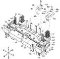
以下、実施形態に係るコネクタについて説明する。図1はコネクタ20を示す斜視図である。図2はコネクタ20の底面図である。なお、図1では第1機器10の上にコネクタ20及び第2機器14が設けられている。図1では、内部の1次モールド部40が2点鎖線で示される。以下の説明において、便宜上、第1機器10に対してコネクタ20及び第2機器14が設けられた側を上、その反対側を下という。また、コネクタ20に対して第2機器14が設けられた側を前側、その反対側を後側という。さらに、前側を向いた状態を基準として、左右が参照される。[Embodiment]
A connector according to an embodiment will be described below. FIG. 1 is a perspective view showing the
本実施形態では、第1機器10用のコネクタ20に端子防水構造30が適用された例が説明される。第1機器10は、電気部品を収容するケース11を備える。ケース11の上方に開口11hが設けられている。開口11hを塞ぐようにコネクタ20が取付けられる。 In this embodiment, an example in which the terminal
コネクタ20は、端子31、32を備える。端子31、32の一端部は、コネクタ20の上側に露出している。端子31、32の一端部は、コネクタ接続等を介して第1機器10外の配線に接続される。端子31、32の他端部はコネクタ20の下側に露出している。端子31、32の他端部は、開口11hを通じてケース11内に配設される。端子31、32の他端部は、コネクタ接続等を介して第1機器10内の配線に接続される。このため、コネクタ20の端子31、32は、第1機器10内の配線と、第1機器10外の配線とを中継接続する役割を果すことができる。 The
コネクタ20のうちケース11の開口11hの周縁部に対向する部分には、シール22が設けられる。ここでは、シール22は、端子31、32の周囲を囲むように環状に設けられる。シール22は、ケース11の開口11hの周縁とコネクタ20の環状対向部との間に介在して隙間をシールし、もって、ケース11とコネクタ20との合せ目から水が浸入することを抑制する。 A
コネクタ20のうち端子31、32が保持される部分の隣に第2機器14が設けられている。第2機器14は、電気部品を収容するケース15を備える。ケース15の下方に開口15hが設けられる。開口15hは、端子31、32の隣において開口している。開口15hは、シール22によって囲まれる領域に向けて開口している。ここでは、ケース15は、コネクタ20の2次モールド部50に対してネジ止等で固定されている。ケース15は、コネクタ20の2次モールド部50と金型一体形成された部分であってもよい。シール22は、端子31、32の周りだけでなく、ケース15の開口15hの周りをも囲んでいる。このため、シール22は、ケース11とコネクタ20との間において、第1機器10と第2機器14との組合せ部分に対して水が浸入することをも抑制している。 A
上記第2機器14は省略されていてもよい。この場合、シールは、端子31、32の周りを囲んでいればよい。 The
コネクタ20についてより具体的に説明する。 The
コネクタ20は、端子31、32と、1次モールド部40と、2次モールド部50とを備える。 The
端子31、32は、銅等の金属板によって形成された部材である。端子31、32は長尺状に形成されている。ここでは、端子31は、曲る経路を描く太幅帯状の金属部材がプレス加工によって厚み方向に曲げられた形状に形成されている。端子32は、端子31よりも細く形成されている。端子32は、曲る経路を描く細幅帯状の金属部材がプレス加工によって厚み方向に曲げられた形状に形成されている。端子31、32の延在方向中間部は直線状のまま又は曲って少なくとも1次モールド部40に埋っている。 The
端子31の両端部は平板状に形成されている。端子32の端部はピン状に形成されている。各端子31、32の端部は、相手側のメス端子に挿入接続される。端子31、32の端部は、筒状のメス端子形状に形成されていてもよい。端子31、32の端部は、相手側の導電部材とハンダ付又はネジ止固定される部分であってもよい。 Both ends of the terminal 31 are formed in a flat plate shape. The ends of the
1次モールド部40は、樹脂等の絶縁材料によって形成される。1次モールド部40は、端子31、32を保持する部分である。ここでは、1次モールド部40は、端子31、32をインサート物として金型成形されることによって形成されている。端子31、32が金型成形時のインサート物とされることは必須ではない。例えば、1次モールド部が金型成形された後に、端子が1次モールド部に装着されてもよい。この場合、1次モールド部に端子をセットするための凹部又は位置決め用の突起が形成されるとよい。 The
2次モールド部50は、樹脂等の絶縁材料によって形成される。2次モールド部50は、1次モールド部40を保持する部分である。ここでは、2次モールド部50は、1次モールド部40をインサート物として金型成形されることによって形成されている。 The
ここでは、2次モールド部50は、2次モールド本体部51と、筒部52と、枠部53とを備える。 Here, the
2次モールド本体部51は、上下方向において、枠部53よりも大きい寸法に形成されている。この2次モールド本体部51内に1次モールド部40が埋っている。1次モールド部40の一部は、2次モールド部50から露出していてもよいし、露出していなくてもよい。ここでは、1次モールド部40の一部は、2次モールド本体部51の下側に露出している。 The secondary
端子31、32を保持する1次モールド部40が2次モールド本体部51に埋った状態となるように、2次モールド部50が金型成形される。このため、端子31、32は、2次モールド部50に対して一定位置に保持される。端子31、32の一端部は、1次モールド部40又は2次モールド本体部51の下部から第1機器10内に向けて突出するように支持される。例えば、本コネクタ20が第1機器10のケース11に取付けられた状態で、端子31、32の一端部が当該ケース11内に設けられた相手側端子に挿入接続されてもよい。 The
2次モールド本体部51の上部に、筒部52が形成されている。ここでは、2つの筒部52が間隔をあけて形成される。それぞれの筒部52の底から、端子31、32の一端部が突出するように支持される。外部の相手側コネクタが筒部52にコネクタ接続される。これにより、当該相手側のコネクタ内の端子に、端子31、32の一端部が接続される。 A
2次モールド本体部51から一側方である前側に延出するようにして、環状、ここでは、方形環状の枠部53が設けられる。枠部53は、ケース11の開口11hの周縁部に沿って配設される。 An
2次モールド本体部51は、1次モールド部40を端子31、32と共に一定位置に保持する部分であり、上記筒部52よりも肉厚に形成される。The secondary
2次モールド部50にシール用溝54が形成される。ここでは、上記筒部52の下部を通り、2次モールド本体部51のうち端子31、32の他端部が突出する部分よりも外側を通る環状経路に沿ってシール用溝54が形成される。このため、シール用溝54は、環状溝である。シール用溝54は、ケース11の開口11hの周縁部に沿って配設されることになる。平面透過視において、シール用溝54によって囲まれる領域内に端子31、32の他端部及びケース15の開口15hが配設される。シール用溝54は、下方に開口する溝形状に形成されている。シール用溝54の横断面形状(延在方向に対して直交する方向の断面)は、方形状であってもよいし、U字状であっても良いし、V字状であってもよい。A sealing
2次モールド本体部51は、シール用溝54の周方向において部分的な位置に形成される。このため、1次モールド部40は、シール用溝54の周方向の一部において2次モールド部50によって保持されている。 The secondary
シール用溝54に、シール22が配設される。シール22は、少なくとも一部がシール用溝54内に配設された状態で、コネクタ20の1次モールド部40とケース11との間をシールする部分である。シール22は、シール用溝54内に充填されたシーリング剤であってもよいし、シール用溝54に嵌め込まれた環状ゴムであってもよい。いずれにせよ、シール22は、シール用溝54によって位置決めされた状態で、開口11hの外周りでケース11とコネクタ20との間の隙間をシールする。 A
上記したように、シール用溝54が形成された部分のうち2次モールド本体部51の部分は比較的肉厚に形成される。金型成形品が肉厚である場合には、樹脂の収縮によってヒケ或はボイドが生じてしまう恐れがある。シール用溝54は、防水目的を果すための部分であるため、当該シール用溝54が形成された部分においては、ヒケ或はボイドの発生が抑制されることが望ましい。本開示においては、2次モールド本体部51のうちシール用溝54が形成された部分でヒケ或はボイドを抑制するため、1次モールド部40のうちシール用溝54に対応する位置に突部40Pが形成されている。 As described above, the portion of the
図3は1次モールド部40を示す斜視図である。図3の上下方向は、図1における上下方向とは逆となっている。また、図3において、1次モールド部40を構成する部品のうちの一部の合体前の状態が2点鎖線で示されている。図4は図2のIV-IV線断面図である。 FIG. 3 is a perspective view showing the
1次モールド部40は、2次モールド部50の2次モールド本体部51内に埋った状態となっている。1次モールド部40は、部分的に2次モールド部50から露出していてもよい。もっとも、防水性を高めるため、シール用溝54が形成された部分では、1次モールド部40は露出しないことが好ましい。また、同様に防水性を高めるため、外部に面する部分では、1次モールド部40は露出しないことが好ましい。 The
1次モールド部40のうちシール用溝54に対応する位置に突部40Pが形成される。ここでは、環状のシール用溝54の一部が2次モールド本体部51に形成される。2次モールド本体部51の下部において、シール用溝54の一部は、直線部54aと、一対の曲線部54bと、一対の直線側部54cとを含む。直線部54aは、端子31、32の他端部の外側で左右方向に延在する直線状をなす。一対の曲線部54bは、直線部54aの両端部で1/4円弧をなして連続する。一対の直線側部54cは、一対の曲線部54bから直線部54aに対して直交する方向に延出する用に連続する。 A
2次モールド本体部51を平面透過視した場合、1次モールド部40は、2次モールド本体部51のうち直線部54a、一対の曲線部54b及び、一対の直線側部54cが存在する領域に埋っている。 When the secondary mold
1次モールド部40のうち上記直線部54a、一対の曲線部54b及び、一対の直線側部54cに対応する領域に突部40Pが形成されている。ここでは、突部40Pは、シール用溝54の底に対して内側に存在している。突部40Pは、2次モールド本体部51内に埋っており、シール用溝54の底面及び両側面には露出していない。このため、シール用溝54の内面の全ては、2次モールド部50を金型成形する際に形成された樹脂面である。
ここでは、突部40Pがシール用溝54の底から2次モールド本体部51内における内側に離れた位置に存在するが、これは必須ではない。例えば、シール用溝54の側面から離れた位置に突部が存在していてもよい。いずれの場合においても、シール用溝54の周囲において2次モールド部を成形するための樹脂の体積が突部の分小さくなる。これにより、シール用溝の形成部分において、樹脂ヒケ或はボイドの発生が抑制される。 Here, the
1次モールド部40は、全体として1つの部品に一体化された構成であってもよいし、複数の部品が組合わされたものであってもよい。ここでは、1次モールド部40が、複数の分割1次モールド部が組合わされた構成である例について説明する。 The
ここでは、1次モールド部40は、中央1次モールド部41と、左右の分割1次モールド部群42、42とに分割された構成とされている。 Here, the
中央1次モールド部41は、複数の分割1次モールド部のうちの1つの例であり、1次モールド部40の幅方向中央に設けられる。中央1次モールド部41は、複数の端子31、32のうちの一部の端子31をインサート物として樹脂によって金型成形されている。中央1次モールド部41は、上下方向に薄く、左右方向に長い細長板状に形成されている。端子31の中間部は必要に応じて曲りつつ前後方向に沿った状態で中央1次モールド部41内に埋っている。中央1次モールド部41の前後の端で、端子31の両端部は互いに逆方向(上下逆方向)に突出するように曲げられている。この中央1次モールド部41が2次モールド本体部51内に埋った状態とされることで、端子31の一端部が2次モールド本体部51の上部の各筒部52内に突出した一定姿勢で保持される。また、端子31の他端部が2次モールド本体部51の下部に突出した一定姿勢で保持される。 The central
中央1次モールド部41が2次モールド部50に埋った状態で、中央1次モールド部41の下側主面(図3において上を向く面)は、シール用溝54における直線部54aの内側に配設される。中央1次モールド部41の下側主面のうちシール用溝54における直線部54aの内側に位置する部分に、左右方向に沿う直線状の分割突部41Pが形成されている。 When the central
中央1次モールド部41の左側及び右側のそれぞれに、分割1次モールド部群42、42が設けられる。左右の分割1次モールド部群42、42は、左右対称形状である。一方側(左側)の分割1次モールド部群42を中心に説明する。 Divided primary
分割1次モールド部群42は、第1分割1次モールド部43と、第2分割1次モールド部44と、第3分割1次モールド部45と、第4分割1次モールド部46とを備える。分割1次モールド部群を構成するモールド部は、より少数であってもよいし、より多数であってもよい。分割1次モールド部群を構成する部分が1つの分割1次モールド部によって構成されていてもよい。 The divided primary
第1分割1次モールド部43と、第2分割1次モールド部44と、第3分割1次モールド部45と、第4分割1次モールド部46は、それぞれ複数の分割1次モールド部のうちの1つの例である。分割1次モールド部43、44、45、46は、それぞれ複数の端子32の一部をインサート物として樹脂によって金型成形されている。分割1次モールド部43、44、45、46の中間部は、上下方向に薄い板状に形成されている。分割1次モールド部43、44、45、46を側面視した状態で、分割1次モールド部43、44、45、46の前後の端部は互いに逆方向(上下方向)に突出している。分割1次モールド部43、44、45、46のそれぞれにおいて、端子32の中間部が分割1次モールド部43、44、45、46内に埋っている。また、端子32の両端部は、分割1次モールド部43、44、45、46の前後の端部において、互いに逆方向(上下方向)に突出している。 The first divided
分割1次モールド部43、44、45、46の中間部の板状部分が上下方向において積層されている。積層状態において、分割1次モールド部43、44、45、46の前後両端が互いに当接し合う。必要に応じて、分割1次モールド部43、44、45、46の中間部の板状部分に互いに嵌り合う位置決め用の凹形状又は凸形状が形成される。これらの当接構造、位置決め構造等によって、分割1次モールド部43、44、45、46は、互いに一定の位置関係に保たれる。 The intermediate plate-like portions of the divided
分割1次モールド部43、44、45、46が組合わされた左右の分割1次モールド部群42、42が2次モールド部50に埋った状態で、端子32の一端部が2次モールド本体部51の上部の各筒部52内に突出した一定姿勢で保持される。また、端子32の他端部が2次モールド本体部51の下部に突出した一定姿勢で保持される。 Left and right divided primary
第1分割1次モールド部43及び第2分割1次モールド部44に着目して、分割1次モールド部群42、42に形成された分割突部43P、44Pについて説明する。 Focusing on the first divided
第2分割1次モールド部44は、中間保持部44aと、上方突出部44bと、下方突出部44cとを備える。中間保持部44aは前後方向に長い板状に形成されている。ここでは、中間保持部44aは、平面視において前端部が中央寄りに突出するL字状に形成されている。中間保持部44aの後端寄りの下側主面(図3において上側の面)は、中間保持部44aの前端寄りの下側主面よりも段部44Sを介して凹んでいる。中間保持部44aの後端寄りの下側主面に、前後方向に沿って延びる細長い位置決め突部44dが形成されている。中間保持部44aの後端部から上方突出部44bが突出し、中間保持部44aの前端部から下方突出部44cが突出している。上方突出部44bと、下方突出部44cとは、互いに逆方向(上下方向)に突出している。複数の端子32の中間部が中間保持部44aに埋った状態で、複数の端子32の一端部が上方突出部44bから突出し、他端部が下方突出部44cから突出している。 The second divided
第1分割1次モールド部43は、中間保持部43aと、上方突出部43bと、下方突出部43cとを備える。中間保持部43aは板状に形成されている。中間保持部43aの上側主面(図3においては隠れている下向きの面)に、上記位置決め突部44dが嵌る位置決め溝が形成されている。中間保持部43aの後端部から上方突出部43bが突出し、中間保持部43aの前端部から下方突出部43cが突出している。上方突出部43bと、下方突出部43cとは、左右方向にずれた位置で、互いに逆方向(上下)に突出している。複数の端子32の中間部が中間保持部43aに埋った状態で、複数の端子32の一端部が上方突出部43bから突出し、他端部が下方突出部43cから突出している。 The first divided
第1分割1次モールド部43における中間保持部43aは、第2分割1次モールド部44における中間保持部44aの後端寄りの下側主面(段部44Sを介して凹んだ部分)に積重ねられる。この状態で、上記位置決め突部44dが中間保持部43aの位置決め溝に嵌る。また、上方突出部43bと上方突出部44bとが前後方向において接触し合う。これにより、第1分割1次モールド部43と第2分割1次モールド部44とは、前後左右方向に位置決めされた状態で、積層された状態となる。 The
分割1次モールド部43、44、45、46が互いに位置決めされていることは必須ではない。分割1次モールド部43、44、45、46をインサート物として2次モールド部50が金型成形される際、外方に突出する端子32の端部を利用して、端子32及び分割1次モールド部43、44、45、46を位置決めできるからである。中央1次モールド部41と、分割1次モールド部群42、42とは、凹凸嵌り合い構造等によって互いに位置決めされていてもよいし、位置決めされていなくてもよい。 It is not essential that the split
分割1次モールド部群42、42が2次モールド部50に埋った状態で、第1分割1次モールド部43の下側主面は、シール用溝54における直線部54aの両端部及び曲線部54bに対して内側に配設される。第1分割1次モールド部43の下側主面のうち直線部54aの両端部及び曲線部54bに対して内側に位置する部分に、直線部分と1/4円弧状の曲線部分とが連続した分割突部43Pが形成されている。 When the divided primary
また、分割1次モールド部群42、42が2次モールド部50に埋った状態で、第2分割1次モールド部44の下側主面は、シール用溝54における直線側部54cに対して内側に配設される。第2分割1次モールド部44の下側主面のうち直線側部54cに対して内側に位置する部分に、直線状の分割突部44Pが形成されている。 Further, in a state in which the divided primary
複数の分割1次モールド部である中央1次モールド部41及び分割1次モールド部群42、42が2次モールド部50に埋って保持された状態で、分割突部41P、43P、44Pは、シール用溝54の底に対して一定距離を保つように、当該シール用溝54の延在方向に沿って並んでいる。 In a state in which the central
より具体的には、中央1次モールド部41及び分割1次モールド部群42、42が2次モールド部50に埋った状態で中央1次モールド部41の下側主面と第1分割1次モールド部43の下側主面とは、同一平面状に位置する。中央1次モールド部41の下側主面に対する分割突部41Pの突出寸法と、第1分割1次モールド部43の下側主面に対する分割突部43Pの突出寸法は、同じに設定されている。また、第1分割1次モールド部43の下側主面に対して第2分割1次モールド部44の下側主面は、段部を介して凹んでいる。第2分割1次モールド部44の下側主面に対する分割突部44Pの突出寸法は、第1分割1次モールド部43の下側主面に対する分割突部43Pの突出寸法よりも、上記凹み分大きい。分割突部41P、43P、44Pは、シール用溝54に沿って並び、かつ、分割突部41P、43P、44Pの下側面は、上下方向において一定の位置に揃えられる。よって、分割突部41P、43P、44Pの下側面は、シール用溝54の底に対して一定距離を保っている。従って、1次モールド部40のうちシール用溝54の底部分の肉厚は一定に揃えられる。なお、ここでは、分割突部41P、43P、44Pの幅は、シール用溝54の幅よりも小さい。分割突部41P、43P、44Pの幅は、シール用溝54の幅と同じであってもよいし、シール用溝54の幅より大きくてもよい。 More specifically, when the central
本実施形態に係るコネクタ20によると、1次モールド部40のうちシール用溝54に対応する位置に突部40Pが形成される。このため、2次モールド部50のうちシール用溝54の底側の肉厚が小さくなる。換言すれば、2次モールド部50のうちシール用溝54を形成するための部分の体積が小さくなる。これにより、金型成形時の冷却過程等において、シール用溝54の周辺部で樹脂のヒケ、ボイド等の発生が抑制される。特に、コネクタ20と第1機器10との間で防水を行うための構成要素であるシール用溝54の周辺部においてヒケ、ボイド等の発生が抑制されるため、良好な防水性が得られる。According to the
また、分割突部41P、43P、44Pは、シール用溝54に対応する部分において部分的に1次モールド部40の主面から突出している。このため、1次モールド部40の全体を大型化しなくてもよく、ひいては、1次モールド部40を保持する2次モールド部50の小型化も図られる。 In addition, the dividing
なお、シール用溝54の周辺部が肉厚となることを抑制するために、2次モールド部50のうちシール用溝54の周辺に肉抜き構造を設けることが考えられる。その場合、2次モールド部50の形状が複雑となり、場合によっては、スライド金型が必要となる。本実施例では、金型構造が複雑化することなく、シール用溝54の周辺部の一部が肉薄に形成され得る。このため、金型コスト増を招くことなく、シール用溝54の周辺部においてヒケ、ボイド等の発生が抑制される。 In order to prevent the peripheral portion of the sealing
また、シール用溝54は、2次モールド部50に対して環状に形成され、1次モールド部40は、シール用溝54の周方向の一部の位置において、2次モールド部50によって保持されている。2次モールド部50のうち1次モールド部40を保持する箇所で、2次モールド部50が肉厚となってヒケ、ボイドが発生することが懸念される。そこで、本実施形態では、突部40Pは、シール用溝54の周方向のうち1次モールド部40が保持される部分に対応する位置に形成される。このため、2次モールド部50のうち1次モールド部40を保持する部分、すなわち、肉厚となりやすい部分で、突部40Pによって効果的にヒケ、ボイドの発生が抑制される。Further, the sealing
これに対して、シール用溝54のうち枠部53に形成された部分については、その周辺部分の肉厚を小さくすることが容易である。このため、ヒケ、ボイド等は元々発生し難い。 On the other hand, it is easy to reduce the thickness of the peripheral portion of the portion of the sealing
また、1次モールド部40は、複数の分割1次モールド部として、中央1次モールド部41、分割1次モールド部43、44、45、46を含む。この場合において、突部40Pは、複数の分割1次モールド部のうちの少なくとも2つである、中央1次モールド部41、第1分割1次モールド部43、第2分割1次モールド部44に形成された分割突部41P、43P、44Pを含む。このため、1次モールド部40が、複数の分割1次モールド部を含む場合においても、複数の分割突部41P、43P、44Pによって、シール用溝54に沿った突部40Pが構成される。 Further, the
また、中央1次モールド部41、分割1次モールド部43、44、45、46が2次モールド部50に保持された状態で、分割突部41P、43P、44Pは、シール用溝54の底に対して一定距離を保つように、シール用溝54の延在方向に沿って並ぶ。このため、シール用溝54の底と突部40Pとの間の肉厚が揃えられる。これにより、2次モールド部の樹脂ヒケ、ボイドの発生が安定して抑制される。Further, in a state in which the central
なお、上記実施形態及び各変形例で説明した各構成は、相互に矛盾しない限り適宜組合わせることができる。 It should be noted that the configurations described in the above embodiment and modifications can be appropriately combined as long as they do not contradict each other.
10 第1機器
11 ケース
11h 開口
14 第2機器
15 ケース
15h 開口
20 コネクタ
22 シール
30 端子防水構造
31 端子
32 端子
40 1次モールド部
40P 突部
41 中央1次モールド部
41P 分割突部
42 分割1次モールド部群
43 第1分割1次モールド部
43P 分割突部
43a 中間保持部
43b 上方突出部
43c 下方突出部
44 第2分割1次モールド部
44P 分割突部
44S 段部
44a 中間保持部
44b 上方突出部
44c 下方突出部
44d 位置決め突部
45 第3分割1次モールド部
46 第4分割1次モールド部
50 2次モールド部
51 2次モールド本体部
52 筒部
53 枠部
54 シール用溝
54a 直線部
54b 曲線部
54c 直線側部10
Claims (3)
Translated fromJapanese前記端子を保持する1次モールド部と、
前記1次モールド部を保持する2次モールド部と、
を備え、
前記2次モールド部にシール用溝が形成され、
前記1次モールド部のうち前記シール用溝の底に対して内側の位置に突部が形成されており、
前記1次モールド部は、複数の分割1次モールド部を含み、
前記突部は、前記複数の分割1次モールド部のうちの少なくとも2つに形成された分割突部を含む、コネクタ。a terminal;
a primary mold portion that holds the terminal;
a secondary mold portion that holds the primary mold portion;
with
A sealing groove is formed in the secondary mold portion,
A protrusion is formed at a positioninside the bottom of the sealing groove in the primary mold portion,
The primary mold section includes a plurality of divided primary mold sections,
The connector, wherein the protrusion includes split protrusions formed in at least two of the plurality of split primary mold sections .
前記シール用溝が、前記2次モールド部に対して環状に形成され、
前記1次モールド部は、前記シール用溝の周方向の一部の位置において、前記2次モールド部によって保持され、
前記突部は、前記シール用溝の周方向のうち前記1次モールド部が保持される部分に形成されている、コネクタ。A connector according to claim 1, wherein
the sealing groove is formed annularly with respect to the secondary mold portion,
The primary mold portion is held by the secondary mold portion at a portion of the seal groove in the circumferential direction,
The connector, wherein the protrusion isformed in a portion of the sealing groove in the circumferential direction where the primary mold portion is held.
前記複数の分割1次モールド部が前記2次モールド部に保持された状態で、前記少なくとも2つの分割突部は、前記シール用溝の底に対して一定距離を保つように、前記シール用溝の延在方向に沿って並ぶ、コネクタ。3. The connector according to claim 1 or 2,
In a state in which the plurality of divided primary mold portions are held by the secondary mold portion, the at least two divided projections are arranged in the sealing groove so as to keep a constant distance from the bottom of the sealing groove. Connectors lined up along the extension direction of
Priority Applications (3)
| Application Number | Priority Date | Filing Date | Title |
|---|---|---|---|
| JP2019118153AJP7151639B2 (en) | 2019-06-26 | 2019-06-26 | connector |
| CN202010522731.8ACN112152008B (en) | 2019-06-26 | 2020-06-10 | Connector with a locking member |
| US16/907,397US11276956B2 (en) | 2019-06-26 | 2020-06-22 | Connector with a primary molding having a protrusion, a secondary molding engaging the protrusion and a sealing groove in the secondary molding aligned with the protrusion |
Applications Claiming Priority (1)
| Application Number | Priority Date | Filing Date | Title |
|---|---|---|---|
| JP2019118153AJP7151639B2 (en) | 2019-06-26 | 2019-06-26 | connector |
Publications (2)
| Publication Number | Publication Date |
|---|---|
| JP2021005478A JP2021005478A (en) | 2021-01-14 |
| JP7151639B2true JP7151639B2 (en) | 2022-10-12 |
Family
ID=73891910
Family Applications (1)
| Application Number | Title | Priority Date | Filing Date |
|---|---|---|---|
| JP2019118153AActiveJP7151639B2 (en) | 2019-06-26 | 2019-06-26 | connector |
Country Status (3)
| Country | Link |
|---|---|
| US (1) | US11276956B2 (en) |
| JP (1) | JP7151639B2 (en) |
| CN (1) | CN112152008B (en) |
Families Citing this family (1)
| Publication number | Priority date | Publication date | Assignee | Title |
|---|---|---|---|---|
| JP7509055B2 (en) | 2021-02-26 | 2024-07-02 | 住友電装株式会社 | connector |
Citations (2)
| Publication number | Priority date | Publication date | Assignee | Title |
|---|---|---|---|---|
| JP2019093634A (en) | 2017-11-22 | 2019-06-20 | 住友電装株式会社 | Connector and its production method |
| JP2020123539A (en) | 2019-01-31 | 2020-08-13 | 矢崎総業株式会社 | Resin molding |
Family Cites Families (21)
| Publication number | Priority date | Publication date | Assignee | Title |
|---|---|---|---|---|
| GB9412094D0 (en)* | 1994-06-16 | 1994-08-03 | Whipp & Bourne Ltd | Obturation plate and a method of fabricating same |
| JPH1187011A (en)* | 1997-09-03 | 1999-03-30 | Yazaki Corp | Connector molding method |
| JP4680231B2 (en)* | 2007-04-18 | 2011-05-11 | トヨタ自動車株式会社 | connector |
| JP4445982B2 (en)* | 2007-06-29 | 2010-04-07 | ホシデン株式会社 | connector |
| JP5485288B2 (en)* | 2008-11-25 | 2014-05-07 | テトラビュー, インコーポレイテッド | High resolution 3D imaging system and method |
| CN101931152B (en)* | 2009-06-23 | 2012-06-27 | 宏致电子股份有限公司 | electrical connector |
| JP5626047B2 (en)* | 2011-03-15 | 2014-11-19 | 住友電装株式会社 | Connector for equipment |
| JP6032224B2 (en)* | 2014-02-24 | 2016-11-24 | 株式会社デンソー | Electrical connector and manufacturing method thereof |
| CN103872508B (en)* | 2014-03-19 | 2016-04-13 | 苏州华旃航天电器有限公司 | The sealed electric connector of a kind of injection moulding |
| JP6311994B2 (en) | 2015-02-20 | 2018-04-18 | 住友電装株式会社 | Terminal structure |
| JP6597393B2 (en)* | 2016-02-29 | 2019-10-30 | 住友電装株式会社 | Resin molded product and its manufacturing method |
| CN205921141U (en)* | 2016-06-30 | 2017-02-01 | 深圳君泽电子有限公司 | USB connector and electronic equipment applying same |
| JP2018206567A (en)* | 2017-06-02 | 2018-12-27 | 住友電装株式会社 | Connector device for substrate |
| KR20200019979A (en)* | 2017-06-23 | 2020-02-25 | 쿄와 기린 가부시키가이샤 | α, β unsaturated amide compounds |
| US11070001B2 (en)* | 2017-07-07 | 2021-07-20 | Hitachi Automotive Systems, Ltd. | Connector formation structure, electronic control apparatus and production method for connector formation structure |
| CN207426217U (en)* | 2017-10-26 | 2018-05-29 | 深圳市沃尔新能源电气科技股份有限公司 | Adaptor connector |
| WO2019172038A1 (en)* | 2018-03-07 | 2019-09-12 | 住友電装株式会社 | Connector |
| JP6891836B2 (en)* | 2018-03-07 | 2021-06-18 | 住友電装株式会社 | Connector and its manufacturing method |
| CN109361096B (en)* | 2018-10-29 | 2020-07-28 | 番禺得意精密电子工业有限公司 | Cable connector |
| CN208938843U (en)* | 2018-10-30 | 2019-06-04 | 上海西艾爱电子有限公司 | A kind of self sealing structure of Manual maintenance switch |
| CN109449644B (en)* | 2018-11-19 | 2024-08-06 | 昆山宏泽电子有限公司 | USB Type-C connector with waterproof structure |
- 2019
- 2019-06-26JPJP2019118153Apatent/JP7151639B2/enactiveActive
- 2020
- 2020-06-10CNCN202010522731.8Apatent/CN112152008B/enactiveActive
- 2020-06-22USUS16/907,397patent/US11276956B2/enactiveActive
Patent Citations (2)
| Publication number | Priority date | Publication date | Assignee | Title |
|---|---|---|---|---|
| JP2019093634A (en) | 2017-11-22 | 2019-06-20 | 住友電装株式会社 | Connector and its production method |
| JP2020123539A (en) | 2019-01-31 | 2020-08-13 | 矢崎総業株式会社 | Resin molding |
Also Published As
| Publication number | Publication date |
|---|---|
| US11276956B2 (en) | 2022-03-15 |
| US20200412049A1 (en) | 2020-12-31 |
| CN112152008B (en) | 2022-05-17 |
| JP2021005478A (en) | 2021-01-14 |
| CN112152008A (en) | 2020-12-29 |
Similar Documents
| Publication | Publication Date | Title |
|---|---|---|
| KR102374481B1 (en) | Reversible dual-position electric connector | |
| KR101897403B1 (en) | Electrical connector and production method thereof | |
| JP4345594B2 (en) | connector | |
| US11569604B2 (en) | Connector | |
| US11303070B2 (en) | Connector and outer conductor | |
| CN115360551A (en) | Connector and connector assembly | |
| JP5924591B2 (en) | connector | |
| CN104471797A (en) | Connector | |
| JP6375246B2 (en) | Connector mating structure | |
| US10236620B2 (en) | Connector having a connector housing with a holding portion for holding a sealing ring | |
| CN104471798A (en) | Connector | |
| JP2015005431A (en) | Connector | |
| CN111146611A (en) | Power supply connector device with improved terminals | |
| JP2009104837A (en) | Connector | |
| JP7151639B2 (en) | connector | |
| JP2020198162A (en) | connector | |
| EP3346557B1 (en) | Waterproof structure for connector | |
| JP7702011B2 (en) | Electrical Connectors | |
| JP3119119B2 (en) | Crimp joint connector | |
| JP2009164145A (en) | Connector | |
| JP5557032B2 (en) | Connector for equipment | |
| US20210143584A1 (en) | Connector structure | |
| JP2022154676A (en) | connector | |
| JP4541999B2 (en) | Shielded connector | |
| JP2024078952A (en) | Waterproof terminal block |
Legal Events
| Date | Code | Title | Description |
|---|---|---|---|
| A521 | Request for written amendment filed | Free format text:JAPANESE INTERMEDIATE CODE: A523 Effective date:20200406 | |
| A621 | Written request for application examination | Free format text:JAPANESE INTERMEDIATE CODE: A621 Effective date:20210928 | |
| A977 | Report on retrieval | Free format text:JAPANESE INTERMEDIATE CODE: A971007 Effective date:20220624 | |
| A131 | Notification of reasons for refusal | Free format text:JAPANESE INTERMEDIATE CODE: A131 Effective date:20220628 | |
| A521 | Request for written amendment filed | Free format text:JAPANESE INTERMEDIATE CODE: A523 Effective date:20220729 | |
| TRDD | Decision of grant or rejection written | ||
| A01 | Written decision to grant a patent or to grant a registration (utility model) | Free format text:JAPANESE INTERMEDIATE CODE: A01 Effective date:20220830 | |
| A61 | First payment of annual fees (during grant procedure) | Free format text:JAPANESE INTERMEDIATE CODE: A61 Effective date:20220912 | |
| R150 | Certificate of patent or registration of utility model | Ref document number:7151639 Country of ref document:JP Free format text:JAPANESE INTERMEDIATE CODE: R150 | |
| R250 | Receipt of annual fees | Free format text:JAPANESE INTERMEDIATE CODE: R250 |