JP7151458B2 - Piston pump, boost liquid supply system and liquid injection device - Google Patents
Piston pump, boost liquid supply system and liquid injection deviceDownload PDFInfo
- Publication number
- JP7151458B2 JP7151458B2JP2018238857AJP2018238857AJP7151458B2JP 7151458 B2JP7151458 B2JP 7151458B2JP 2018238857 AJP2018238857 AJP 2018238857AJP 2018238857 AJP2018238857 AJP 2018238857AJP 7151458 B2JP7151458 B2JP 7151458B2
- Authority
- JP
- Japan
- Prior art keywords
- flow path
- liquid
- channel
- liquid nitrogen
- piston pump
- Prior art date
- Legal status (The legal status is an assumption and is not a legal conclusion. Google has not performed a legal analysis and makes no representation as to the accuracy of the status listed.)
- Active
Links
- 239000007788liquidSubstances0.000titleclaimsdescription153
- 238000002347injectionMethods0.000titleclaimsdescription74
- 239000007924injectionSubstances0.000titleclaimsdescription74
- 239000002826coolantSubstances0.000claimsdescription23
- 238000007599dischargingMethods0.000claimsdescription5
- IJGRMHOSHXDMSA-UHFFFAOYSA-NAtomic nitrogenChemical compoundN#NIJGRMHOSHXDMSA-UHFFFAOYSA-N0.000description242
- 229910052757nitrogenInorganic materials0.000description121
- 238000001816coolingMethods0.000description56
- 239000000110cooling liquidSubstances0.000description25
- 239000007789gasSubstances0.000description12
- 238000011144upstream manufacturingMethods0.000description7
- XLYOFNOQVPJJNP-UHFFFAOYSA-NwaterSubstancesOXLYOFNOQVPJJNP-UHFFFAOYSA-N0.000description6
- 230000002093peripheral effectEffects0.000description4
- 238000004140cleaningMethods0.000description2
- 239000000463materialSubstances0.000description2
- 238000000034methodMethods0.000description2
- 239000002699waste materialSubstances0.000description2
- 229910000831SteelInorganic materials0.000description1
- 230000005540biological transmissionEffects0.000description1
- 238000009835boilingMethods0.000description1
- 239000000470constituentSubstances0.000description1
- 230000007423decreaseEffects0.000description1
- 239000010959steelSubstances0.000description1
Images

Landscapes
- Reciprocating Pumps (AREA)
- Details Of Reciprocating Pumps (AREA)
Description
Translated fromJapanese本発明は、ピストンポンプ、昇圧液体供給システム及び液体噴射装置に関するものである。 The present invention relates to a piston pump, a pressurized liquid supply system, and a liquid injection device.
例えば特許文献1には、水に換えて液体窒素を噴射することによって、対象物の加工や洗浄を行う方法が開示されている。水を用いるウォータジェット法では、切削片等や汚れが水に交じることから、水自体の処理に配慮する必要があり、大量の二次廃棄物が発生する場合がある。一方で、噴射後に気化する液体窒素を用いる場合には、液体窒素は切削片や汚れと分離して気化するため、二次廃棄物を発生させることなく、加工や洗浄が可能となる。 For example,
ところで、液体窒素等の低温液化ガスをノズルから噴射する場合には、低温液化ガスを液体状態のまま昇圧する。例えば、このような低温液化ガスの昇圧はピストンポンプによって行われる。しかしながら、ピストンポンプで低温液化ガスを昇圧すると、低温液化ガスの温度が上昇する。このため、シリンダ内に低温液化ガスを導入する導入流路とシリンダ内から昇圧した低温液化ガスを吐出する吐出流路とが併設されている場合には、吐出流路を流れる昇圧後の低温液化ガスによって、導入流路を流れる低温液化ガスが昇温してしまう。昇圧前の低温液化ガスが昇温されると、ピストンポンプにおいて密度が低い低温液化ガスを昇圧することになり、ピストンポンプにおける効率が低下する。なお、このような問題は、沸点が低い低温液化ガスを昇圧するピストンポンプで顕著なるが、水を昇圧するピストンポンプでも同様に発生する。 By the way, when a low-temperature liquefied gas such as liquid nitrogen is injected from a nozzle, the pressure of the low-temperature liquefied gas is increased while it is in a liquid state. For example, the pressurization of such cryogenic liquefied gas is performed by a piston pump. However, when the pressure of the cryogenic liquefied gas is increased by the piston pump, the temperature of the cryogenic liquefied gas rises. For this reason, when an introduction channel for introducing low-temperature liquefied gas into the cylinder and a discharge channel for discharging pressurized low-temperature liquefied gas from inside the cylinder are provided in parallel, low-temperature liquefaction after pressurization flowing through the discharge channel The gas raises the temperature of the low-temperature liquefied gas flowing through the introduction channel. When the temperature of the low-temperature liquefied gas before pressurization is increased, the low-density low-temperature liquefied gas is pressurized in the piston pump, and the efficiency of the piston pump decreases. Such a problem is conspicuous in a piston pump that pressurizes low-temperature liquefied gas with a low boiling point, but it also occurs in a piston pump that pressurizes water.
本発明は、上述する問題点に鑑みてなされたもので、液体を昇圧するピストンポンプやこのピストンポンプを用いて液体の昇圧を行う昇圧液体供給システム及び液体噴射装置において、導入流路を通じてシリンダに供給される液体の高密度化を可能とすることを目的とする。 The present invention has been made in view of the above-described problems, and provides a piston pump that pressurizes a liquid, a pressurized liquid supply system that pressurizes a liquid using the piston pump, and a liquid injection device that includes a cylinder through an introduction passage. The object is to enable a higher density of the liquid to be supplied.
本発明は、上記課題を解決するための手段として、以下の構成を採用する。 The present invention employs the following configurations as means for solving the above problems.
第1の発明は、シリンダ内に昇圧対象の液体を導入する導入流路と上記シリンダ内から昇圧された上記液体を吐出する吐出流路とが併設されたヘッド部を有するピストンポンプであって、上記導入流路を流れる上記昇圧対象の液体を熱交換により冷却する冷却材の流路となる冷却材流路を備えるという構成を採用する。 A first invention is a piston pump having a head portion provided with an introduction channel for introducing a liquid to be pressurized into a cylinder and a discharge channel for discharging the liquid pressurized from the cylinder, A configuration is adopted in which a coolant channel is provided as a coolant channel for cooling the liquid to be pressurized flowing through the introduction channel by heat exchange.
第2の発明は、上記第1の発明において、上記導入流路の径方向外側から上記ヘッド部と接続されると共に上記ヘッド部の外壁面との間に上記冷却材流路の少なくとも一部を形成する流路形成部材を備えるという構成を採用する。 In a second aspect of the invention, in the first aspect, the coolant flow path is connected to the head portion from the radially outer side of the introduction flow path, and at least a portion of the coolant flow path is formed between the outer wall surface of the head portion and the coolant flow path. A configuration is adopted in which a flow path forming member is provided.
第3の発明は、上記第2の発明において、上記流路形成部材が、上記ヘッド部の外壁面との間に上記冷却材を貯留するバッファ室を上記冷却材流路の一部として形成する溝部と、上記バッファ室に接続された入口流路と、上記入口流路と異なる位置にて上記バッファ室に接続された出口流路とを有するという構成を採用する。 In a third aspect based on the second aspect, the flow path forming member forms, as part of the coolant flow path, a buffer chamber for storing the coolant between the flow path forming member and an outer wall surface of the head portion. A configuration is adopted that has a groove portion, an inlet channel connected to the buffer chamber, and an outlet channel connected to the buffer chamber at a position different from the inlet channel.
第4の発明は、上記第3の発明において、上記入口流路が、上記吐出流路よりも上記導入流路に近い位置にて上記バッファ室に接続されているという構成を採用する。 A fourth aspect of the invention employs a configuration in which the inlet channel is connected to the buffer chamber at a position closer to the introduction channel than the discharge channel in the third aspect.
第5の発明は、上記第4の発明において、上記バッファ室が、上記導入流路における上記液体の流れ方向に沿った方向から見て、上記導入流路を全周から囲う環状に設けられているという構成を採用する。 In a fifth aspect based on the fourth aspect, the buffer chamber is provided in an annular shape surrounding the entire circumference of the introduction channel when viewed from a direction along the flow direction of the liquid in the introduction channel. Adopt the configuration that there is
第6の発明は、上記第5の発明において、上記出口流路が、上記ヘッド部を挟んで上記入口流路と対向する位置にて上記バッファ室に接続されているという構成を採用する。 A sixth aspect of the invention employs a configuration in which the outlet channel is connected to the buffer chamber at a position facing the inlet channel with the head portion interposed therebetween in the fifth aspect.
第7の発明は、上記第2~第6いずれかの発明において、上記流路形成部材が、上記ヘッド部を上記シリンダに固定する固定部材であるという構成を採用する。 A seventh invention employs a configuration in which the flow path forming member is a fixing member for fixing the head portion to the cylinder in any one of the second to sixth inventions.
第8の発明は、液体を噴射するノズルに上記液体を昇圧して供給する昇圧液体供給システムであって、上記液体を昇圧するピストンポンプとして上記第1~第7いずれかの発明であるピストンポンプを備えるという構成を採用する。 An eighth invention is a pressurized liquid supply system for pressurizing and supplying the liquid to a nozzle for injecting the liquid, wherein the piston pump according to any one of the first to seventh inventions is a piston pump for pressurizing the liquid. A configuration is adopted.
第9の発明は、液体を噴射するノズルと、上記ノズルに上記液体を昇圧して供給する昇圧液体供給システムとを備える液体噴射装置であって、上記昇圧液体供給システムとして、上記第8の発明である昇圧液体供給システムを備えるという構成を採用する。 A ninth aspect of the invention is a liquid ejecting apparatus comprising a nozzle for injecting liquid and a pressurized liquid supply system for supplying the liquid to the nozzle in a pressurized state, wherein the pressurized liquid supply system is the eighth aspect of the invention. is provided with a pressurized liquid supply system.
本発明によれば、シリンダ内に昇圧対象の液体を導入する導入流路を流れる液体を熱交換により冷却する冷却材が流れる冷却材流路を有している。このため、冷却材流路に冷却材を流すことによって、昇圧前の液体を冷却することが可能となり、導入流路を通じてシリンダに供給される液体の高密度化することが可能となる。 According to the present invention, the cylinder has a coolant passage through which a coolant that cools the liquid flowing through the introduction passage for introducing the liquid to be pressurized by heat exchange flows. Therefore, by flowing the coolant through the coolant channel, it is possible to cool the liquid before the pressure is increased, and it is possible to increase the density of the liquid supplied to the cylinder through the introduction channel.
以下、図面を参照して、本発明に係るピストンポンプ、昇圧液体供給システム及び液体噴射装置の一実施形態について説明する。 An embodiment of a piston pump, a pressurized liquid supply system, and a liquid injection device according to the present invention will be described below with reference to the drawings.
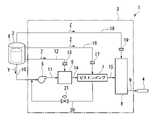
図1は、本実施形態の液体窒素噴射装置1(液体噴射装置)の概略構成を示すフロー図である。この図に示すように、本実施形態の液体窒素噴射装置1は、貯蔵タンク2と、液体窒素昇圧システム3(昇圧液体供給システム)と、ノズル4とを備えている。 FIG. 1 is a flowchart showing a schematic configuration of a liquid nitrogen injection device 1 (liquid injection device) according to this embodiment. As shown in this figure, the liquid
貯蔵タンク2は、液体窒素X(液体)を貯蔵する圧力タンクであり、液体窒素昇圧システム3と接続されている。なお、本実施形態の液体窒素噴射装置1は、この貯蔵タンク2を備えずに外部から液体窒素Xの供給を受ける構成とすることも可能である。なお、本実施形態において、貯蔵タンク2に貯蔵された液体窒素Xは、昇圧されてノズル4に供給される他、冷却材としても用いられる。以下の説明において、最終的にノズル4に供給される昇圧対象の液体窒素Xを噴射用液体窒素Yと称し、冷却材として用いられる液体窒素Xを冷却用液体窒素Zと称する。液体窒素昇圧システム3は、貯蔵タンク2から供給された噴射用液体窒素Yを一定の噴射圧にまで昇圧するものであり、ノズル4と接続されている。ノズル4は、液体窒素昇圧システム3から供給された噴射用液体窒素Yを先端部から噴射する。 The storage tank 2 is a pressure tank that stores liquid nitrogen X (liquid) and is connected to the liquid
液体窒素昇圧システム3について、より詳細に説明する。液体窒素昇圧システム3は、上述のように噴射用液体窒素Yを噴射するノズル4に噴射用液体窒素Yを昇圧して供給するシステムであり、図1に示すように、液体窒素昇圧システム3は、ブーストポンプ5と、第1熱交換器6と、ピストンポンプ7と、第2熱交換器8と、フレキシブルチューブ9を備えている。 The liquid
ブーストポンプ5は、接続配管10を介して貯蔵タンク2と接続されている。このブーストポンプ5は、接続配管10を介して供給される噴射用液体窒素Yをピストンポンプ7が吸い込み可能な圧力まで昇圧するポンプである。このブーストポンプ5としては、例えば遠心ポンプが用いられる。このようなブーストポンプ5は、接続配管11によって第1熱交換器6と接続されており、接続配管11を通じて第1熱交換器6に向けて噴射用液体窒素Yを圧送する。 The
第1熱交換器6は、冷却用配管12によって貯蔵タンク2と接続されており、接続配管11を介してブーストポンプ5から供給される噴射用液体窒素Yと、冷却用配管12を介して供給される冷却用液体窒素Zとを熱交換することによって、ブーストポンプ5から供給される噴射用液体窒素Yを冷却する。このような第1熱交換器6は、例えばプレートフィン型の熱交換器である。このような第1熱交換器6は、接続配管14によってピストンポンプ7と接続されており、接続配管14を通じてピストンポンプ7に向けてブーストポンプ5で昇圧された噴射用液体窒素Yを排出する。 The
本実施形態においては、ブーストポンプ5よりも第1熱交換器6がピストンポンプ7に近接して配置されている。つまり、本実施形態においては、先にブーストポンプ5で噴射用液体窒素Yが昇圧され、昇圧された噴射用液体窒素Yが第1熱交換器6で冷却されてピストンポンプ7に供給される。このため、先に冷却してからブーストポンプ5で昇圧する場合と比較して、より低温で密度の高い噴射用液体窒素Yをピストンポンプ7に供給することができる。 In this embodiment, the
なお、冷却用配管12の途中部位には、オリフィス13が設置されている。オリフィス13は、冷却用配管12の途中部位に設けられる抵抗部であり、冷却用液体窒素Zの流れに対する抵抗となっている。このオリフィス13は、冷却用配管12のオリフィス13よりも上流側の部位の圧力を維持するための絞り流路である。冷却用の液体窒素として第1熱交換器6に供給された冷却用液体窒素Zは、第1熱交換器6にて減圧される。オリフィス13によって、冷却用配管12の上流側が第1熱交換器6の内部の圧力に応じて減圧されることを防止することができる。 An
ピストンポンプ7は、接続配管14を介して第1熱交換器6から供給される噴射用液体窒素Yを、ノズル4での噴射圧まで昇圧するためのポンプである。このピストンポンプ7は、送出配管15を介して第2熱交換器8と接続されており、昇圧した噴射用液体窒素Yを第2熱交換器8に圧送する。また、本実施形態においては、ピストンポンプ7は、冷却用配管16を介して貯蔵タンク2と接続されており、冷却用配管16を通じて供給される冷却用液体窒素Zによって、第1熱交換器6から供給される噴射用液体窒素Yを冷却する。 The
なお、冷却用配管16の途中部位には、オリフィス17が設置されている。オリフィス17は、冷却用配管16の途中部位に設けられる抵抗部であり、冷却用液体窒素Zの流れに対する抵抗となっている。このオリフィス17は、冷却用配管16のオリフィス17よりも上流側の部位の圧力を維持するための絞り流路である。冷却用の液体窒素としてピストンポンプ7に供給された冷却用液体窒素Zは、ピストンポンプ7にて減圧される。オリフィス17によって、冷却用配管16の上流側が減圧されることを防止することができる。 An
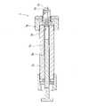
図2は、ピストンポンプ7の概略構成を示す断面図である。この図に示すように、ピストンポンプ7は、シリンダ7aと、スリーブ7bと、ピストン7cと、ヘッド部7dと、流入弁7e、吐出弁7fと、固定部材7g(流路形成部材)とを備えている。 FIG. 2 is a cross-sectional view showing a schematic configuration of the
シリンダ7aは、中空の筒体であり、内部が噴射用液体窒素Yの収容空間とされている。また、シリンダ7aの先端部の外周面には、固定部材7gを螺合するための雄ネジ部が形成されている。スリーブ7bは、シリンダ7aの内部に嵌合された筒状部材であり、シリンダ7aの内壁面に外周面が当接された状態で配置されている。ピストン7cは、シリンダ7aに囲まれた空間に往復同可能に配置された棒状部材である。ピストン7cは、不図示の動力源から動力を伝達されることによって、シリンダ7aの軸心に沿った方向に移動される。 The
図3は、ヘッド部7dを含む拡大図である。ヘッド部7dは、固定部材7gによってシリンダ7aの片側の端面に配して圧接されるように配置された円柱状の部材である。このヘッド部7dは、図3に示すように、内部に導入流路7d1と、吐出流路7d2とが設けられている。導入流路7d1は、シリンダ7aの内部に噴射用液体窒素Yを案内するための流路であり、シリンダ7aの軸心に沿った方向に延伸されている。この導入流路7d1は、図1に示す接続配管11に接続されており、接続配管11から昇圧用の噴射用液体窒素Yが供給される。吐出流路7d2は、シリンダ7aの内部で昇圧された噴射用液体窒素Yをヘッド部7dの外部に吐出するための流路であり、導入流路7d1と平行に設けられている。この吐出流路7d2は、図1に示す送出配管15と接続されており、昇圧した噴射用液体窒素Yを送出配管15に供給する。このように本実施形態においては、導入流路7d1と吐出流路7d2とが、ヘッド部7dに併設されている。 FIG. 3 is an enlarged view including the
また、図3に示すように、ヘッド部7dは、先端部よりもシリンダ7aの軸心を中心とする径方向外側に膨出された大径部7d3を有している。この大径部7d3は、シリンダ7a側の面がシリンダ7aの端面と当接され、この面と反対側の面が固定部材7gと当接されている。本実施形態では、この大径部7d3がシリンダ7aと固定部材7gとによって挟持されることによって、ヘッド部7dがシリンダ7aに対して固定されている。 Further, as shown in FIG. 3, the
流入弁7eは、ヘッド部7dのシリンダ7a側の端部に設けられており、導入流路7d1における逆流を防止する。吐出弁7fは、ヘッド部7dのシリンダ7aと反対側の端部である先端部に対して設けられており、吐出流路7d2における逆流を防止する。 The
固定部材7gは、ヘッド部7dをシリンダ7aに固定すると共に、冷却用液体窒素Z(図1に示す冷却用配管16を介して供給される液体窒素X)を流すための冷却流路R(冷却材流路)を形成する部材である。この固定部材7gは、1つの部材であるが、図3に示すように、噴射用液体窒素Yが吐出される側に位置する天壁部7g1と、天壁部7g1よりもシリンダ7a側に配置される囲壁部7g2とに分けて説明する。 The fixing
天壁部7g1は、中央部にヘッド部7dの先端部が挿通可能とされた貫通孔7g3を有している。この天壁部7g1の貫通孔7g3の内壁面には、貫通孔7g3の径方向外側に向けて窪む環状の溝部7g4が設けられている。この溝部7g4は、ヘッド部7dの先端部の外壁面との間に環状のバッファ室R1を形成する。また、天壁部7g1には、溝部7g4(すなわちバッファ室R1)に接続された入口流路R2及び出口流路R3が設けられている。 The top wall portion 7g1 has a through hole 7g3 in the center portion through which the tip portion of the
入口流路R2は、溝部7g4から天壁部7g1の外周面まで天壁部7g1の径方向に天壁部7g1を貫通して設けられており、図1に示す冷却用配管16と接続されている。この入口流路R2は、冷却用配管16から供給される冷却用液体窒素Zをバッファ室R1まで案内するための流路である。 The inlet flow path R2 is provided through the top wall portion 7g1 in the radial direction of the top wall portion 7g1 from the groove portion 7g4 to the outer peripheral surface of the top wall portion 7g1, and is connected to the cooling
出口流路R3は、入口流路R2と異なる位置にて溝部7g4(すなわちバッファ室R1)と接続され、溝部7g4から天壁部7g1の外周面まで天壁部7g1の径方向に天壁部7g1を貫通して設けられている。この出口流路R3は、バッファ室R1から固定部材7gの外部に冷却用液体窒素Zを排出するための流路である。 The outlet channel R3 is connected to the groove portion 7g4 (that is, the buffer chamber R1) at a position different from that of the inlet channel R2, and extends radially of the ceiling wall portion 7g1 from the groove portion 7g4 to the outer peripheral surface of the ceiling wall portion 7g1. is provided through the The outlet channel R3 is a channel for discharging the cooling liquid nitrogen Z from the buffer chamber R1 to the outside of the fixing
本実施形態においては、上述のバッファ室R1と、入口流路R2と、出口流路R3とによって、冷却流路Rが形成されている。つまり、固定部材7gは、ヘッド部7dの外壁面との間に冷却流路Rの一部であるバッファ室R1を形成すると共に、バッファ室R1に繋がる入口流路R2と出口流路R3とを有している。 In this embodiment, the cooling channel R is formed by the buffer chamber R1, the inlet channel R2, and the outlet channel R3. That is, the fixing
冷却流路Rの一部を形成するバッファ室R1は、ヘッド部7dの導入流路7d1における噴射用液体窒素Yの流れ方向に沿った方向から見て、導入流路7d1を全周から囲う環状に設けられている。この冷却流路Rによれば、ヘッド部7dの導入流路7d1を流れる噴射用液体窒素Yを全周方向から冷却することができる。また、バッファ室R1は入口流路R2及び出口流路R3と比較して容積が大きく、冷却用液体窒素Zを一時的に導入流路7d1の周囲に大量に貯留することができる。このため、導入流路7d1の周囲をより低温にすることができ、噴射用液体窒素Yをより低温まで冷却することが可能となる。 The buffer chamber R1 forming a part of the cooling channel R has an annular shape surrounding the entire periphery of the introduction channel 7d1 when viewed from the direction along the flow direction of the jetting liquid nitrogen Y in the introduction channel 7d1 of the head portion 7d. is provided in According to this cooling channel R, the jetting liquid nitrogen Y flowing through the introduction channel 7d1 of the
また、このような冷却流路Rの一部を形成する入口流路R2と出口流路R3とは、貫通孔7g3に挿通されたヘッド部7dを挟んで対向する位置に配置されている。つまり、出口流路R3は、入口流路R2とヘッド部7dを挟んで対向する位置すなわち入口流路R2から最も遠い位置に配置されている。このため、入口流路R2から出口流路R3に至る経路を長く確保することができ、より効率的に導入流路7d1を流れる噴射用液体窒素Yを冷却することができる。 In addition, the inlet flow path R2 and the outlet flow path R3 forming part of the cooling flow path R are arranged at positions opposed to each other with the
また、入口流路R2は、導入流路7d1に最も近接した位置にてバッファ室R1と接続されている。つまり、本実施形態において、入口流路R2は、吐出流路7d2よりも導入流路7d1に近い位置にてバッファ室R1に接続されている。このため、入口流路R2を流れる低温の冷却用液体窒素Zが導入流路7d1に近接した位置にてバッファ室R1に供給される。 In addition, the inlet channel R2 is connected to the buffer chamber R1 at a position closest to the introduction channel 7d1. That is, in the present embodiment, the inlet channel R2 is connected to the buffer chamber R1 at a position closer to the introduction channel 7d1 than to the discharge channel 7d2. Therefore, the low-temperature cooling liquid nitrogen Z flowing through the inlet channel R2 is supplied to the buffer chamber R1 at a position close to the introduction channel 7d1.
囲壁部7g2は、天壁部7g1のシリンダ7a側の面からシリンダ7a側に延出して設けられた部位であり、径方向における中央部に開口部7g5が設けられている。囲壁部7g2は、外径寸法が天壁部7g1の外形寸法と同一に設定されており、外壁面が天壁部7g1の外壁面と面一とされている。一方、囲壁部7g2の開口部7g5の直径寸法(すなわち囲壁部7g2の内径寸法)は、天壁部7g1の貫通孔7g3の直径寸法(すなわち天壁部7g1の内径寸法)よりも大きく設定されている。このため、全体として筒状とされた固定部材7gの内壁面には、天壁部7g1と囲壁部7g2との境界部分に段差部が設けられている。 The surrounding wall portion 7g2 is a portion extending from the
開口部7g5の内径寸法は、ヘッド部7dの大径部7d3の外径寸法よりも大きく設定されている。また、開口部7g5の深さ寸法は、ヘッド部7dの大径部7d3の長さ寸法よりも大きく設定されている。このため、図3に示すように、開口部7g5の内部には、ヘッド部7dの大径部7d3の全体が収容されている。 The inner diameter dimension of the opening 7g5 is set larger than the outer diameter dimension of the large diameter portion 7d3 of the
また、囲壁部7g2の内壁面には、シリンダ7aの雄ネジ部に螺合するための雌ネジ部が設けられている。この囲壁部7g2の雌ネジ部がシリンダ7aの雄ネジ部に螺合されることによって、固定部材7gがシリンダ7aに対して固定される。 The inner wall surface of the surrounding wall portion 7g2 is provided with a female screw portion for screwing with the male screw portion of the
このような構成のピストンポンプ7においては、ピストン7cが引かれると、流入弁7eが導入流路7d1を開放し、導入流路7d1を介して噴射用液体窒素Yがシリンダ7aの内部に供給される。その後、ピストン7cが押されると、流入弁7eが閉じることによってシリンダ7aの内部が閉空間となり、ピストン7cの移動に伴って噴射用液体窒素Yが昇圧される。シリンダ7a内の噴射用液体窒素Yが所定の圧力まで昇圧されると、吐出弁7fが吐出流路7d2を開放し、昇圧された噴射用液体窒素Yがヘッド部7dから送出配管15に供給される。 In the
また、ピストンポンプ7においては、上述の噴射用液体窒素Yの昇圧動作中に、固定部材7gの入口流路R2に冷却用液体窒素Zが供給される。入口流路R2に供給される冷却用液体窒素Zは、大気圧あるいは大気圧に近い圧力の液体窒素X(ブーストポンプ5によって昇圧されていない液体窒素X)であり、導入流路7d1を流れる噴射用液体窒素Yよりも低温となっている。このため、導入流路7d1を流れる噴射用液体窒素Yは、入口流路R2からバッファ室R1に流れ込んだ冷却用液体窒素Zとの熱交換によって冷却される。なお、バッファ室R1に供給された冷却用液体窒素Zは、出口流路R3から外部に排出され、例えば大気開放される。 In addition, in the
図1に戻り、第2熱交換器8は、送出配管15から供給される昇圧後の噴射用液体窒素Yを、後冷却配管18から供給される冷却用液体窒素Zと熱交換することによって噴射温度まで冷却する熱交換器である。この第2熱交換器8は、例えばコイルチューブ型やシェルアンドチューブ型の熱交換器であり、ピストンポンプ7で昇圧された加圧状態の噴射用液体窒素Yと、後冷却配管18から供給される低圧かつ低温の冷却用液体窒素Zとを熱交換する。 Returning to FIG. 1, the
後冷却配管18は、貯蔵タンク2と第2熱交換器8とを接続する配管である。この後冷却配管18の途中部位には、オリフィス19が設けられている。オリフィス19は、後冷却配管18の途中部位に設けられる抵抗部であり、冷却用液体窒素Zの流れに対する抵抗となっている。このオリフィス19は、後冷却配管18のオリフィス19よりも上流側の部位の圧力を位置するための絞り流路である。第2熱交換器8に供給された冷却用液体窒素Zは、第2熱交換器8にて減圧される。オリフィス19によって、後冷却配管18の上流側が減圧されることが防止される。 The
フレキシブルチューブ9は、第2熱交換器8とノズル4とを接続する鋼管であり、ノズル4を作業者が容易に姿勢変更なように第2熱交換器8と接続している。第2熱交換器8は、このようなフレキシブルチューブ9を介してノズル4と接続されており、昇圧後の噴射用液体窒素Yを冷却してノズル4に供給する。 The
さらに、本実施形態の液体窒素噴射装置1は、ピストンポンプ7が吸引しなかった噴射用液体窒素Yをブーストポンプ5に返流する返流配管20を備えている。また、返流配管20の途中部位には、返流配管20の流路面積を調節可能なバルブ21が設けられている。なお、バルブ21に換えてオリフィスを設置しても良い。つまり、返流配管20を介して返流される噴射用液体窒素Yの流量が適正となるように、返流配管20にバルブ21やオリフィス等を設置する。 Furthermore, the liquid
このような構成の本実施形態の液体窒素噴射装置1では、貯蔵タンク2に貯蔵された液体窒素Xが噴射用液体窒素Yとしてブーストポンプ5に供給される。噴射用液体窒素Yは、ブーストポンプ5で昇圧された後、第1熱交換器6で冷却されて密度が高められる。第1熱交換器6で冷却された噴射用液体窒素Yは、ピストンポンプ7に供給され、上述の冷却流路Rを流れる液体窒素Xとの熱交換によってさらに冷却されて密度を高められた状態とされてから昇圧される。ピストンポンプ7で昇圧された噴射用液体窒素Yは、第2熱交換器8で冷却され、その後にノズル4に供給される。 In the liquid
以上のような本実施形態の液体窒素噴射装置1に備えられるピストンポンプ7によれば、シリンダ7a内に噴射用液体窒素Yを導入する導入流路7d1を流れる噴射用液体窒素Yを熱交換により冷却する冷却用液体窒素Zが流れる冷却流路Rを有している。このため、冷却流路Rに冷却用液体窒素Zを流すことによって、昇圧前の噴射用液体窒素Yを冷却することが可能となり、導入流路7d1を通じてシリンダ7aに供給される噴射用液体窒素Yを高密度化することが可能となる。したがって、本実施形態の液体窒素噴射装置1によれば、ピストンポンプ7を効率化することができる。 According to the
また、本実施形態のピストンポンプ7においては、導入流路7d1の径方向外側からヘッド部7dと接続されると共にヘッド部7dの外壁面との間に冷却流路Rの少なくとも一部(バッファ室R1)を形成する固定部材7gを備えている。このため、本実施形態のピストンポンプ7によれば、シリンダ7aの内部に供給される直前の噴射用液体窒素Yを冷却することができ、シリンダ7aの内部に供給される噴射用液体窒素Yの密度をより高めることが可能となる。 Further, in the
また、本実施形態のピストンポンプ7においては、固定部材7gは、ヘッド部7dの外壁面との間に冷却用液体窒素Zを貯留するバッファ室R1を冷却流路Rの一部として形成する溝部7g4と、バッファ室R1に接続された入口流路R2と、入口流路R2と異なる位置にてバッファ室R1に接続された出口流路R3とを有している。このため、本実施形態のピストンポンプ7によれば、バッファ室R1において、冷却用液体窒素Zを一時的に貯留することができ、導入流路7d1の周囲により多くの冷熱を蓄えることが可能となる。したがって、本実施形態のピストンポンプ7によれば、シリンダ7aの内部に供給される噴射用液体窒素Yをより確実に冷却して噴射用液体窒素Yの密度をより高めることが可能となる。 In addition, in the
また、本実施形態のピストンポンプ7においては、入口流路R2は、吐出流路よりも導入流路7d1に近い位置にてバッファ室R1に接続されている。このため、本実施形態のピストンポンプ7によれば、最も温度が低い冷却用液体窒素Zをバッファ室R1の導入流路7d1に近接した領域に供給することができ、昇圧用の噴射用液体窒素Yをより低温まで冷却することが可能となる。 In addition, in the
また、本実施形態のピストンポンプ7においては、バッファ室R1は、導入流路7d1における噴射用液体窒素Yの流れ方向に沿った方向から見て、導入流路7d1を全周から囲う環状に設けられている。このため、本実施形態のピストンポンプ7によれば、導入流路7d1を流れる噴射用液体窒素Yを導入流路7d1の全周方向から冷却することができ、より効率的に噴射用液体窒素Yを冷却することが可能となる。 Further, in the
また、本実施形態のピストンポンプ7においては、出口流路R3は、ヘッド部7dを挟んで入口流路R2と対向する位置にてバッファ室R1に接続されている。このため、本実施形態のピストンポンプ7によれば、入口流路R2から出口流路R3に至る経路を最も長く確保することが可能となり、噴射用液体窒素Yをより効率的に冷却することができる。 In addition, in the
また、本実施形態のピストンポンプ7においては、ヘッド部7dをシリンダ7aに固定する固定部材7gによって、冷却流路Rを形成している。このため、冷却流路Rを形成するための部材を、ヘッド部7dをシリンダ7aに固定するための部材と兼用することができる。したがって、本実施形態のピストンポンプ7によれば、部品点数の増加を抑制しつつ冷却流路Rを設けることができる。 Further, in the
以上、添付図面を参照しながら本発明の好適な実施形態について説明したが、本発明は、上記実施形態に限定されないことは言うまでもない。上述した実施形態において示した各構成部材の諸形状や組み合わせ等は一例であって、本発明の趣旨から逸脱しない範囲において設計要求等に基づき種々変更可能である。 Although the preferred embodiments of the present invention have been described above with reference to the accompanying drawings, it goes without saying that the present invention is not limited to the above embodiments. The various shapes, combinations, and the like of the constituent members shown in the above-described embodiment are merely examples, and can be variously changed based on design requirements and the like without departing from the gist of the present invention.
例えば、上記実施形態においては、液体窒素噴射装置1及び液体窒素昇圧システム3では、単一のピストンポンプ7を備える構成を採用した。しかしながら、本発明はこれに限定されるものではない。例えば、並列にあるいは直列にピストンポンプ7を複数設置する構成を採用することも可能である。 For example, in the above embodiment, the liquid
また、上記実施形態においては、固定部材7gによって冷却流路Rを形成する構成を採用した。しかしながら、本発明はこれに限定されるものではない。例えば、ヘッド部7dの内部に冷却流路Rを形成する構成を採用することも可能である。このような場合には、例えば、導入流路7d1と吐出流路7d2との間に冷却流路Rを形成することも可能である。このような場合には、吐出流路7d2から導入流路7d1に伝わる熱を、冷却流路Rを流れる冷却用液体窒素Zで吸収することが可能となる。 Moreover, in the above-described embodiment, the configuration in which the cooling flow path R is formed by the fixing
また、上記実施形態において、ヘッド部7dの内部に吐出流路7d2を囲う断熱スリーブを設置するようにしても良い。このような構成を採用することによって、吐出流路7d2から導入流路7d1への伝熱をさらに抑制することが可能となる。 Further, in the above-described embodiment, a heat insulating sleeve surrounding the discharge flow path 7d2 may be installed inside the
また、上記実施形態においては、冷却流路Rが環状のバッファ室R1を設ける構成について説明した。しかしながら、本発明はこれに限定されるものではない。例えば、冷却流路Rが、導入流路7d1を囲むような螺旋状の流路を備える構成を採用することも可能である。 Further, in the above embodiment, the configuration in which the cooling flow path R is provided with the annular buffer chamber R1 has been described. However, the invention is not limited to this. For example, it is possible to employ a configuration in which the cooling channel R includes a spiral channel surrounding the introduction channel 7d1.
また、上記実施形態においては、冷却流路Rが単一の入口流路R2と単一の出口流路R3とを備える構成を採用した。しかしながら、本発明はこれに限定されるものではない。例えば、入口流路R2及び出口流路R3のいずれかあるいは両方を複数備える構成を採用することも可能である。 Moreover, in the above-described embodiment, the configuration in which the cooling flow path R has a single inlet flow path R2 and a single outlet flow path R3 is adopted. However, the invention is not limited to this. For example, it is also possible to employ a configuration in which either or both of the inlet channel R2 and the outlet channel R3 are provided in plurality.
また、上記実施形態においては、入口流路R2が出口流路R3よりも上方に配置された構成について説明した。しかしながら、本発明はこれに限定されるものではない。入口流路R2を出口流路R3の下方に配置することも可能である。入口流路R2を出口流路R3よりも上方に配置することによって、気化した冷却用液体窒素Zが上昇する力により冷却用液体窒素Zをバッファ室R1に長い間貯留させることができる。一方、入口流路R2を出口流路R3の下方に配置することによって、気化した冷却用液体窒素Zが出口流路R3から外部に排気されやすくし、冷却流路Rの流路抵抗を低減することが可能となる。 Moreover, in the above-described embodiment, the configuration in which the inlet channel R2 is arranged above the outlet channel R3 has been described. However, the invention is not limited to this. It is also possible to arrange the inlet channel R2 below the outlet channel R3. By arranging the inlet flow path R2 above the outlet flow path R3, the cooling liquid nitrogen Z can be stored in the buffer chamber R1 for a long time due to the upward force of the vaporized cooling liquid nitrogen Z. On the other hand, by arranging the inlet channel R2 below the outlet channel R3, the vaporized cooling liquid nitrogen Z is easily discharged to the outside from the outlet channel R3, and the channel resistance of the cooling channel R is reduced. becomes possible.
また、上記実施形態においては、ピストンポンプ7において液体窒素Xを昇圧する構成について説明した。しかしながら、本発明はこれに限定されるものではない。ピストンポンプ7で昇圧する液体は特に限定されるものではなく、例えば水をピストンポンプ7で昇圧する構成を採用することも可能である。 Further, in the above-described embodiment, the configuration for pressurizing the liquid nitrogen X in the
また、上記実施形態においては、液体窒素Xを冷却材として用いる構成について説明した。しかしながら、本発明はこれに限定されるものではなく、他の液体等を冷却材として用いることも可能である。 Further, in the above embodiment, the configuration using the liquid nitrogen X as the coolant has been described. However, the present invention is not limited to this, and other liquids or the like can be used as the coolant.
また、上記実施形態においては、噴射用液体窒素Yの流れ方向にて、第1熱交換器6よりも上流側にブーストポンプ5を設置する構成を採用した。しかしながら、本発明はこれに限定されるものではなく、噴射用液体窒素Yの流れ方向にて、第1熱交換器6よりも下流側にブーストポンプ5を設置する構成を採用することも可能である。 Further, in the above-described embodiment, the configuration in which the
1……液体窒素噴射装置(液体噴射装置)、2……貯蔵タンク、3……液体窒素昇圧システム(昇圧液体供給システム)、4……ノズル、5……ブーストポンプ、6……第1熱交換器、7……ピストンポンプ、7a……シリンダ、7b……スリーブ、7c……ピストン、7d……ヘッド部、7d1……導入流路、7d2……吐出流路、7d3……大径部、7e……流入弁、7f……吐出弁、7g……固定部材(流路形成部材)、7g1……天壁部、7g2……囲壁部、7g3……貫通孔、7g4……溝部、7g5……開口部、8……第2熱交換器、9……フレキシブルチューブ、10……接続配管、11……接続配管、12……冷却用配管、13……オリフィス、14……接続配管、15……送出配管、16……冷却用配管、17……オリフィス、18……後冷却配管、19……オリフィス、20……返流配管、21……バルブ、R……冷却流路(冷却材流路)、R1……バッファ室、R2……入口流路、R3……出口流路、X……液体窒素、Y……噴射用液体窒素、Z……冷却用液体窒素 1... liquid nitrogen injection device (liquid injection device), 2... storage tank, 3... liquid nitrogen boosting system (boosting liquid supply system), 4... nozzle, 5... boost pump, 6...
Claims (6)
Translated fromJapanese前記導入流路を流れる前記昇圧対象の液体を熱交換により冷却する冷却材の流路となる冷却材流路を備え、
前記導入流路の径方向外側から前記ヘッド部と接続されると共に前記ヘッド部の外壁面との間に前記冷却材流路の少なくとも一部を形成する流路形成部材を備え、
前記流路形成部材は、
前記ヘッド部の外壁面との間に前記冷却材を貯留するバッファ室を前記冷却材流路の一部として形成する溝部と、
前記バッファ室に接続された入口流路と、
前記入口流路と異なる位置にて前記バッファ室に接続された出口流路と
を有し、
前記入口流路は、前記吐出流路よりも前記導入流路に近い位置にて前記バッファ室に接続されている
ことを特徴とするピストンポンプ。A piston pump having a head portion provided with an introduction channel for introducing a liquid to be pressurized into a cylinder and a discharge channel for discharging the liquid pressurized from the cylinder,
a coolant flow path serving as a flow path for a coolant that cools the liquid to be pressurized flowing through the introduction flow path by heat exchange;
a flow path forming member connected to the head section from the radially outer side of the introduction flow path and forming at least part of the coolant flow path between the head section and an outer wall surface of the head section;
The flow path forming member is
a groove portion forming a buffer chamber for storing the coolant between itself and the outer wall surface of the head portion as a part of the coolant flow path;
an inlet channel connected to the buffer chamber;
an outlet channel connected to the buffer chamber at a position different from the inlet channel;
has
The inlet channel is connected to the buffer chamber at a position closer to the introduction channel than to the discharge channel.
A piston pump characterized by:
前記導入流路を流れる前記昇圧対象の液体を熱交換により冷却する冷却材の流路となる冷却材流路を備え、
前記導入流路の径方向外側から前記ヘッド部と接続されると共に前記ヘッド部の外壁面との間に前記冷却材流路の少なくとも一部を形成する流路形成部材を備え、
前記流路形成部材は、前記ヘッド部を前記シリンダに固定する固定部材である
ことを特徴とするピストンポンプ。A piston pump having a head portion provided with an introduction channel for introducing a liquid to be pressurized into a cylinder and a discharge channel for discharging the liquid pressurized from the cylinder,
a coolant flow path serving as a flow path for a coolant that cools the liquid to be pressurized flowing through the introduction flow path by heat exchange;
a flow path forming member connected to the head section from the radially outer side of the introduction flow path and forming at least part of the coolant flow path between the head section and an outer wall surface of the head section;
The flow path forming member is a fixing member that fixes the head portion to the cylinder.
A piston pump characterized by:
前記昇圧液体供給システムとして、請求項5記載の昇圧液体供給システムを備えることを特徴とする液体噴射装置。A liquid ejecting apparatus comprising a nozzle for ejecting liquid and a pressurized liquid supply system for pressurizing and supplying the liquid to the nozzle,
A liquid injection apparatus comprising the pressurized liquid supply system according to claim5 as the pressurized liquid supply system.
Priority Applications (1)
| Application Number | Priority Date | Filing Date | Title |
|---|---|---|---|
| JP2018238857AJP7151458B2 (en) | 2018-12-20 | 2018-12-20 | Piston pump, boost liquid supply system and liquid injection device |
Applications Claiming Priority (1)
| Application Number | Priority Date | Filing Date | Title |
|---|---|---|---|
| JP2018238857AJP7151458B2 (en) | 2018-12-20 | 2018-12-20 | Piston pump, boost liquid supply system and liquid injection device |
Publications (2)
| Publication Number | Publication Date |
|---|---|
| JP2020101111A JP2020101111A (en) | 2020-07-02 |
| JP7151458B2true JP7151458B2 (en) | 2022-10-12 |
Family
ID=71139183
Family Applications (1)
| Application Number | Title | Priority Date | Filing Date |
|---|---|---|---|
| JP2018238857AActiveJP7151458B2 (en) | 2018-12-20 | 2018-12-20 | Piston pump, boost liquid supply system and liquid injection device |
Country Status (1)
| Country | Link |
|---|---|
| JP (1) | JP7151458B2 (en) |
Citations (4)
| Publication number | Priority date | Publication date | Assignee | Title |
|---|---|---|---|---|
| JP2001153064A (en) | 1999-11-22 | 2001-06-05 | Ebara Corp | Reciprocating pump |
| US20060053165A1 (en) | 2004-09-03 | 2006-03-09 | Nitrocision L.L.C. | System and method for delivering cryogenic fluid |
| WO2018143419A1 (en) | 2017-02-03 | 2018-08-09 | イーグル工業株式会社 | Liquid supply system |
| WO2018198234A1 (en) | 2017-04-26 | 2018-11-01 | 株式会社島津製作所 | Liquid feeding device and fluid chromatograph |
- 2018
- 2018-12-20JPJP2018238857Apatent/JP7151458B2/enactiveActive
Patent Citations (4)
| Publication number | Priority date | Publication date | Assignee | Title |
|---|---|---|---|---|
| JP2001153064A (en) | 1999-11-22 | 2001-06-05 | Ebara Corp | Reciprocating pump |
| US20060053165A1 (en) | 2004-09-03 | 2006-03-09 | Nitrocision L.L.C. | System and method for delivering cryogenic fluid |
| WO2018143419A1 (en) | 2017-02-03 | 2018-08-09 | イーグル工業株式会社 | Liquid supply system |
| WO2018198234A1 (en) | 2017-04-26 | 2018-11-01 | 株式会社島津製作所 | Liquid feeding device and fluid chromatograph |
Also Published As
| Publication number | Publication date |
|---|---|
| JP2020101111A (en) | 2020-07-02 |
Similar Documents
| Publication | Publication Date | Title |
|---|---|---|
| KR20190134672A (en) | Pressure Accumulation Cryogenic Fluid Delivery System | |
| JP5699773B2 (en) | Fuel injection device and fuel supply system using the same | |
| JP7151458B2 (en) | Piston pump, boost liquid supply system and liquid injection device | |
| JP2014152646A (en) | Fuel injection nozzle | |
| WO2017112842A1 (en) | Liquid atomizing nozzle insert with colliding jets | |
| JP7151457B2 (en) | Piston pump, boost liquid supply system and liquid injection device | |
| KR101954560B1 (en) | Spray nozzles and deaerators | |
| JP6493832B2 (en) | Laser oscillation cooling device | |
| JP6624492B2 (en) | Method and apparatus for vaporizing liquefied carbon dioxide | |
| US10030622B2 (en) | Distributed fuel injection equipment | |
| JP5945974B2 (en) | Condensation and mixing apparatus and evaporative gas reliquefaction apparatus having the same | |
| JP6920478B2 (en) | Liquefied fluid supply system and liquefied fluid injection device | |
| KR20170079791A (en) | Cryogenic tank of cryogenic liquid and cooling apparatus and method | |
| KR20120135499A (en) | Piping structures and liquefied natural gas storage tanks comprising the same | |
| JP2008121638A (en) | Cooling system of air compressor | |
| JP6673749B2 (en) | Gas-liquid mixer | |
| KR102614712B1 (en) | Pressure boosting device for cryogenic liquid fuel tank | |
| CN109578806A (en) | A kind of process unit of LNG flash steam (BOG) pressurization condensing recovery | |
| KR102700634B1 (en) | Injection device with double injection nozzle | |
| JP2007078278A (en) | Evaporative cooling device | |
| KR20160035128A (en) | Ethylene liquid vaporize system using sea water | |
| KR20150112673A (en) | Liquid oxygen tank management system for submarine and management method thereof | |
| JP2008121640A (en) | Cooling system of air compressor | |
| KR20070060606A (en) | Vehicle ELP Fuel System | |
| JP2005201342A (en) | High pressure gas filling system and high pressure gas filling method |
Legal Events
| Date | Code | Title | Description |
|---|---|---|---|
| A621 | Written request for application examination | Free format text:JAPANESE INTERMEDIATE CODE: A621 Effective date:20210812 | |
| A977 | Report on retrieval | Free format text:JAPANESE INTERMEDIATE CODE: A971007 Effective date:20220518 | |
| A131 | Notification of reasons for refusal | Free format text:JAPANESE INTERMEDIATE CODE: A131 Effective date:20220524 | |
| A521 | Request for written amendment filed | Free format text:JAPANESE INTERMEDIATE CODE: A523 Effective date:20220623 | |
| TRDD | Decision of grant or rejection written | ||
| A01 | Written decision to grant a patent or to grant a registration (utility model) | Free format text:JAPANESE INTERMEDIATE CODE: A01 Effective date:20220830 | |
| A61 | First payment of annual fees (during grant procedure) | Free format text:JAPANESE INTERMEDIATE CODE: A61 Effective date:20220912 | |
| R151 | Written notification of patent or utility model registration | Ref document number:7151458 Country of ref document:JP Free format text:JAPANESE INTERMEDIATE CODE: R151 |